Embed Size (px)
Citation preview
Model G58
2-1
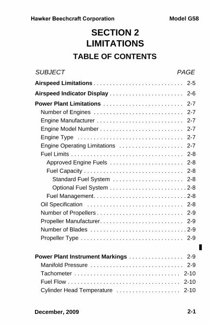
SECTION 2LIMITATIONS
TABLE OF CONTENTS
SUBJECT PAGE
December, 2009
Airspeed Limitations . . . . . . . . . . . . . . . . . . . . . . . . . . . . 2-5
Airspeed Indicator Display . . . . . . . . . . . . . . . . . . . . . . . 2-6
Power Plant Limitations . . . . . . . . . . . . . . . . . . . . . . . . . 2-7Number of Engines . . . . . . . . . . . . . . . . . . . . . . . . . . . . 2-7Engine Manufacturer . . . . . . . . . . . . . . . . . . . . . . . . . . . 2-7Engine Model Number . . . . . . . . . . . . . . . . . . . . . . . . . . 2-7Engine Type . . . . . . . . . . . . . . . . . . . . . . . . . . . . . . . . . 2-7Engine Operating Limitations . . . . . . . . . . . . . . . . . . . . 2-7Fuel Limits . . . . . . . . . . . . . . . . . . . . . . . . . . . . . . . . . . . 2-8
Approved Engine Fuels . . . . . . . . . . . . . . . . . . . . . . . 2-8Fuel Capacity . . . . . . . . . . . . . . . . . . . . . . . . . . . . . . . 2-8
Standard Fuel System . . . . . . . . . . . . . . . . . . . . . . 2-8Optional Fuel System . . . . . . . . . . . . . . . . . . . . . . . . 2-8
Fuel Management. . . . . . . . . . . . . . . . . . . . . . . . . . . . . 2-8Oil Specification . . . . . . . . . . . . . . . . . . . . . . . . . . . . . . 2-8Number of Propellers . . . . . . . . . . . . . . . . . . . . . . . . . . . 2-9Propeller Manufacturer. . . . . . . . . . . . . . . . . . . . . . . . . . 2-9Number of Blades . . . . . . . . . . . . . . . . . . . . . . . . . . . . . . 2-9Propeller Type . . . . . . . . . . . . . . . . . . . . . . . . . . . . . . . . 2-9
Power Plant Instrument Markings . . . . . . . . . . . . . . . . . 2-9Manifold Pressure . . . . . . . . . . . . . . . . . . . . . . . . . . . . . 2-9Tachometer . . . . . . . . . . . . . . . . . . . . . . . . . . . . . . . . . 2-10Fuel Flow . . . . . . . . . . . . . . . . . . . . . . . . . . . . . . . . . . . 2-10Cylinder Head Temperature . . . . . . . . . . . . . . . . . . . . 2-10
sec02toc.fm Page 1 Monday, December 14, 2009 3:42 PM
Model G58
2-2 December, 2009
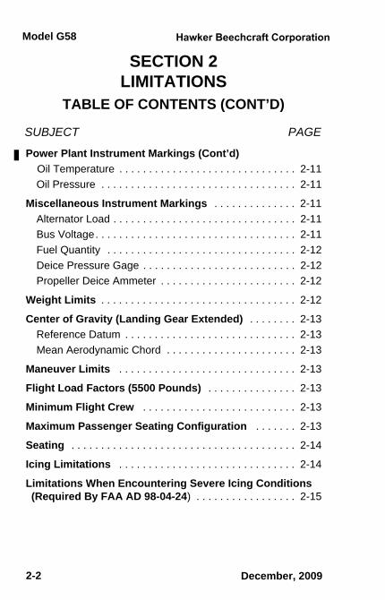
SECTION 2LIMITATIONS
TABLE OF CONTENTS (CONT’D)
SUBJECT PAGE
Power Plant Instrument Markings (Cont’d) Oil Temperature . . . . . . . . . . . . . . . . . . . . . . . . . . . . . . 2-11Oil Pressure . . . . . . . . . . . . . . . . . . . . . . . . . . . . . . . . . 2-11
Miscellaneous Instrument Markings . . . . . . . . . . . . . . 2-11Alternator Load . . . . . . . . . . . . . . . . . . . . . . . . . . . . . . . 2-11Bus Voltage. . . . . . . . . . . . . . . . . . . . . . . . . . . . . . . . . . 2-11Fuel Quantity . . . . . . . . . . . . . . . . . . . . . . . . . . . . . . . . 2-12Deice Pressure Gage . . . . . . . . . . . . . . . . . . . . . . . . . . 2-12Propeller Deice Ammeter . . . . . . . . . . . . . . . . . . . . . . . 2-12
Weight Limits . . . . . . . . . . . . . . . . . . . . . . . . . . . . . . . . . 2-12
Center of Gravity (Landing Gear Extended) . . . . . . . . 2-13Reference Datum . . . . . . . . . . . . . . . . . . . . . . . . . . . . . 2-13Mean Aerodynamic Chord . . . . . . . . . . . . . . . . . . . . . . 2-13
Maneuver Limits . . . . . . . . . . . . . . . . . . . . . . . . . . . . . . 2-13
Flight Load Factors (5500 Pounds) . . . . . . . . . . . . . . . 2-13
Minimum Flight Crew . . . . . . . . . . . . . . . . . . . . . . . . . . 2-13
Maximum Passenger Seating Configuration . . . . . . . 2-13
Seating . . . . . . . . . . . . . . . . . . . . . . . . . . . . . . . . . . . . . . 2-14
Icing Limitations . . . . . . . . . . . . . . . . . . . . . . . . . . . . . . 2-14
Limitations When Encountering Severe Icing Conditions(Required By FAA AD 98-04-24) . . . . . . . . . . . . . . . . . 2-15
sec02toc.fm Page 2 Monday, December 14, 2009 3:42 PM
Model G58
2-3
SECTION 2LIMITATIONS
TABLE OF CONTENTS (CONT’D)
SUBJECT PAGE
December, 2009
Avionics . . . . . . . . . . . . . . . . . . . . . . . . . . . . . . . . . . . . . . 2-16General . . . . . . . . . . . . . . . . . . . . . . . . . . . . . . . . . . . . . 2-16Garmin G1000 Integrated Avionics System . . . . . . . . . . 2-17
GPS Navigation . . . . . . . . . . . . . . . . . . . . . . . . . . . . . 2-23Garmin GFC 700 Autopilot System (Autopilot,
Flight Director, Electric Trim) . . . . . . . . . . . . . . . . . . 2-26L-3 Communications SKYWATCH SKY497
Traffic Advisory System (if installed) . . . . . . . . . . . . 2-27Weather Radar . . . . . . . . . . . . . . . . . . . . . . . . . . . . . . 2-27Garmin Terrain Awareness and
Warning System (TAWS). . . . . . . . . . . . . . . . . . . . . 2-28
Placards/Markings . . . . . . . . . . . . . . . . . . . . . . . . . . . . . 2-29
Kinds Of Operations . . . . . . . . . . . . . . . . . . . . . . . . . . . 2-41
Kinds Of Operations Equipment List . . . . . . . . . . . . . 2-41
sec02toc.fm Page 3 Monday, December 14, 2009 3:42 PM
Model G58
2-4 December, 2009
Section 2Limitations
THIS PAGE INTENTIONALLY LEFT BLANK
sec02toc.fm Page 4 Monday, December 14, 2009 3:42 PM
LimitationsSection 2
Model G58
2-5
Document Date
2-5
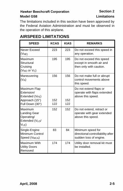
The limitations included in this section have been approved bythe Federal Aviation Administration and must be observed inthe operation of this airplane.
AIRSPEED LIMITATIONSSPEED KCAS KIAS REMARKS
Never Exceed(VNE)
223 223 Do not exceed this speed in any operation.
Maximum Structural Cruising (VNO or VC)
195 195 Do not exceed this speed except in smooth air and then only with caution.
Maneuvering (VA)
156 156 Do not make full or abrupt control movements above this speed.
Maximum Flap Extension/Extended (VFE) Approach (15°)Full Down (30°)
152122
152122
Do not extend flaps or operate with flaps extended above this speed.
Maximum Landing Gear Operating/Extended (VLO/VLE)
152 152 Do not extend, retract or operate with gear extended above this speed.
Single-Engine Minimum Control Speed (VMCA)
83 84 Minimum speed for directional controllability after sudden loss of engine.
Maximum With Utility Doors Removed
174 174 Utility door removal kit must be installed.
April, 2008
sec02.fm Page 5 Thursday, May 1, 2008 2:15 PM
Limitations Model G58Section 2
2 - 6
Document Date
2-6
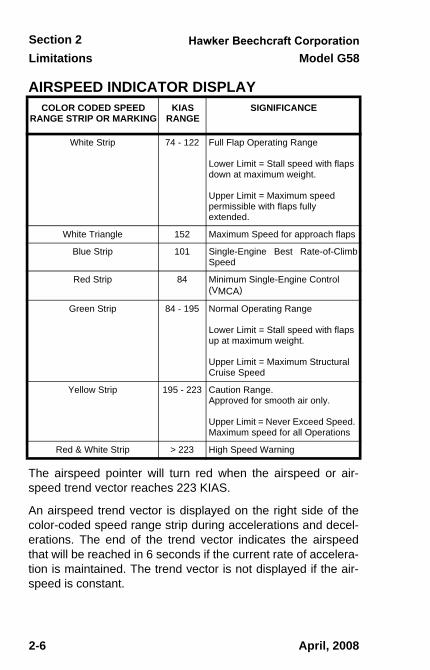
AIRSPEED INDICATOR DISPLAY
The airspeed pointer will turn red when the airspeed or air-speed trend vector reaches 223 KIAS.
An airspeed trend vector is displayed on the right side of thecolor-coded speed range strip during accelerations and decel-erations. The end of the trend vector indicates the airspeedthat will be reached in 6 seconds if the current rate of accelera-tion is maintained. The trend vector is not displayed if the air-speed is constant.
COLOR CODED SPEED RANGE STRIP OR MARKING
KIAS RANGE
SIGNIFICANCE
White Strip 74 - 122 Full Flap Operating Range
Lower Limit = Stall speed with flaps down at maximum weight.
Upper Limit = Maximum speed permissible with flaps fully extended.
White Triangle 152 Maximum Speed for approach flaps
Blue Strip 101 Single-Engine Best Rate-of-ClimbSpeed
Red Strip 84 Minimum Single-Engine Control (VMCA)
Green Strip 84 - 195 Normal Operating Range
Lower Limit = Stall speed with flaps up at maximum weight.
Upper Limit = Maximum Structural Cruise Speed
Yellow Strip 195 - 223 Caution Range.Approved for smooth air only.
Upper Limit = Never Exceed Speed. Maximum speed for all Operations
Red & White Strip > 223 High Speed Warning
April, 2008
sec02.fm Page 6 Thursday, May 1, 2008 2:15 PM
LimitationsSection 2
Model G58
2-7
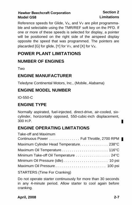
Reference speeds for Glide, VX, and VY are pilot programma-ble and selectable using the TMR/REF soft key on the PFD. Ifone or more of these speeds is selected for display, a pointerwill be positioned on the right side of the airspeed displayopposite the speed that was programmed. The pointers areplacarded [G] for glide, [Y] for VY, and [X] for VX.
POWER PLANT LIMITATIONS NUMBER OF ENGINES Two
ENGINE MANUFACTURER Teledyne Continental Motors, Inc., (Mobile, Alabama)
ENGINE MODEL NUMBER IO-550-C
ENGINE TYPE Normally aspirated, fuel-injected, direct-drive, air-cooled, six-cylinder, horizontally opposed, 550-cubic-inch displacement,300 H.P.
ENGINE OPERATING LIMITATIONS Take-off and MaximumContinuous Power . . . . . . . . . . . . . . . Full Throttle, 2700 RPMMaximum Cylinder Head Temperature. . . . . . . . . . . . . . 238°CMaximum Oil Temperature . . . . . . . . . . . . . . . . . . . . . . . 116°CMinimum Take-off Oil Temperature . . . . . . . . . . . . . . . . . 24°CMinimum Oil Pressure (idle) . . . . . . . . . . . . . . . . . . . . . . 10 psiMaximum Oil Pressure . . . . . . . . . . . . . . . . . . . . . . . . . 100 psi
STARTERS (Time For Cranking)
Do not operate starter continuously for more than 30 secondsin any 4-minute period. Allow starter to cool again beforecranking.
April, 2008
58-590000-67A8_sec02.fm Page 7 Wednesday, May 11, 2011 3:48 PM
Limitations Model G58Section 2
2-8
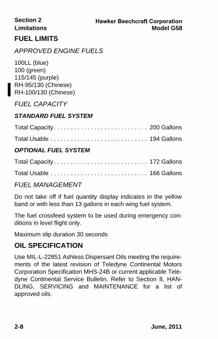
FUEL LIMITSAPPROVED ENGINE FUELS
100LL (blue) 100 (green)115/145 (purple)RH-95/130 (Chinese)RH-100/130 (Chinese)
FUEL CAPACITY
STANDARD FUEL SYSTEM
Total Capacity . . . . . . . . . . . . . . . . . . . . . . . . . . . . 200 Gallons
Total Usable . . . . . . . . . . . . . . . . . . . . . . . . . . . . . 194 Gallons
OPTIONAL FUEL SYSTEM
Total Capacity . . . . . . . . . . . . . . . . . . . . . . . . . . . . 172 Gallons
Total Usable . . . . . . . . . . . . . . . . . . . . . . . . . . . . . 166 Gallons
FUEL MANAGEMENT
Do not take off if fuel quantity display indicates in the yellowband or with less than 13 gallons in each wing fuel system.
The fuel crossfeed system to be used during emergency con-ditions in level flight only.
Maximum slip duration 30 seconds
OIL SPECIFICATIONUse MIL-L-22851 Ashless Dispersant Oils meeting the require-ments of the latest revision of Teledyne Continental MotorsCorporation Specification MHS-24B or current applicable Tele-dyne Continental Service Bulletin. Refer to Section 8, HAN-DLING, SERVICING and MAINTENANCE for a list ofapproved oils.
June, 2011
58-590000-67A8_sec02.fm Page 8 Wednesday, May 11, 2011 3:48 PM
LimitationsSection 2
Model G58
2-9
Document Date
2-9
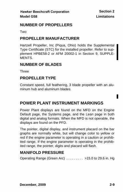
NUMBER OF PROPELLERSTwo
PROPELLER MANUFACTURER Hartzell Propeller, Inc (Piqua, Ohio) holds the SupplementalType Certificate (STC) for the installed propeller. Refer to sup-plement HPBE58-2 or AFM 20002-1 in Section 9, SUPPLE-MENTS.
NUMBER OF BLADES Three
PROPELLER TYPEConstant speed, full feathering, 3 blade propeller with an alu-minum hub and aluminum blades.
POWER PLANT INSTRUMENT MARKINGS Power Plant displays are found on the MFD on the EngineDefault page, the Systems page, and the Lean page in bothdigital and analog formats. When the MFD is not operable, thedisplays are found on the PFD.
The pointer, digital display, and instrument placard on the bargraphs are normally white, but will change color to yellow orred if the engine parameter is operating in a caution or prohib-ited range. If the engine parameter is operating in the prohib-ited range, the pointer, digits and placard will flash.
MANIFOLD PRESSURE Operating Range (Green Arc) . . . . . . . . . >15.0 to 29.6 in. Hg
December, 2009
sec02.fm Page 9 Tuesday, December 15, 2009 8:29 AM
Limitations Model G58Section 2
2 - 10
Document Date
2-10
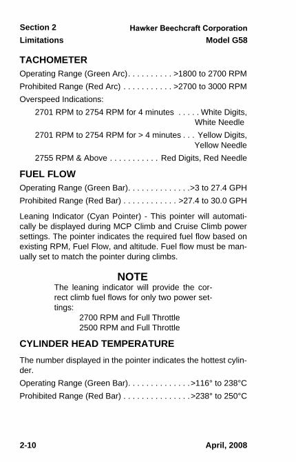
TACHOMETER Operating Range (Green Arc). . . . . . . . . . >1800 to 2700 RPMProhibited Range (Red Arc) . . . . . . . . . . . >2700 to 3000 RPMOverspeed Indications:
2701 RPM to 2754 RPM for 4 minutes . . . . . White Digits, White Needle
2701 RPM to 2754 RPM for > 4 minutes . . . Yellow Digits, Yellow Needle
2755 RPM & Above . . . . . . . . . . . Red Digits, Red Needle
FUEL FLOW Operating Range (Green Bar). . . . . . . . . . . . . .>3 to 27.4 GPHProhibited Range (Red Bar) . . . . . . . . . . . . >27.4 to 30.0 GPH
Leaning Indicator (Cyan Pointer) - This pointer will automati-cally be displayed during MCP Climb and Cruise Climb powersettings. The pointer indicates the required fuel flow based onexisting RPM, Fuel Flow, and altitude. Fuel flow must be man-ually set to match the pointer during climbs.
NOTEThe leaning indicator will provide the cor-rect climb fuel flows for only two power set-tings: 2700 RPM and Full Throttle 2500 RPM and Full Throttle
CYLINDER HEAD TEMPERATURE The number displayed in the pointer indicates the hottest cylin-der.Operating Range (Green Bar). . . . . . . . . . . . . .>116° to 238°CProhibited Range (Red Bar) . . . . . . . . . . . . . . .>238° to 250°C
April, 2008
sec02.fm Page 10 Tuesday, December 15, 2009 8:29 AM
LimitationsSection 2
Model G58
2-11
Document Date
2-11
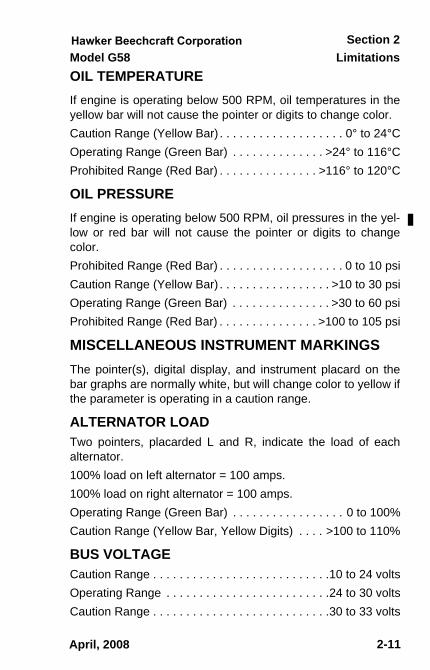
OIL TEMPERATURE If engine is operating below 500 RPM, oil temperatures in theyellow bar will not cause the pointer or digits to change color.Caution Range (Yellow Bar) . . . . . . . . . . . . . . . . . . . 0° to 24°COperating Range (Green Bar) . . . . . . . . . . . . . . >24° to 116°CProhibited Range (Red Bar) . . . . . . . . . . . . . . . >116° to 120°C
OIL PRESSURE If engine is operating below 500 RPM, oil pressures in the yel-low or red bar will not cause the pointer or digits to changecolor.Prohibited Range (Red Bar) . . . . . . . . . . . . . . . . . . . 0 to 10 psiCaution Range (Yellow Bar) . . . . . . . . . . . . . . . . . >10 to 30 psiOperating Range (Green Bar) . . . . . . . . . . . . . . . >30 to 60 psiProhibited Range (Red Bar) . . . . . . . . . . . . . . . >100 to 105 psi
MISCELLANEOUS INSTRUMENT MARKINGSThe pointer(s), digital display, and instrument placard on thebar graphs are normally white, but will change color to yellow ifthe parameter is operating in a caution range.
ALTERNATOR LOADTwo pointers, placarded L and R, indicate the load of eachalternator.100% load on left alternator = 100 amps.100% load on right alternator = 100 amps.Operating Range (Green Bar) . . . . . . . . . . . . . . . . . 0 to 100%Caution Range (Yellow Bar, Yellow Digits) . . . . >100 to 110%
BUS VOLTAGECaution Range . . . . . . . . . . . . . . . . . . . . . . . . . . .10 to 24 voltsOperating Range . . . . . . . . . . . . . . . . . . . . . . . . .24 to 30 voltsCaution Range . . . . . . . . . . . . . . . . . . . . . . . . . . .30 to 33 volts
April, 2008
sec02.fm Page 11 Thursday, May 1, 2008 2:15 PM
Limitations Model G58Section 2
2 - 12
Document Date
2-12
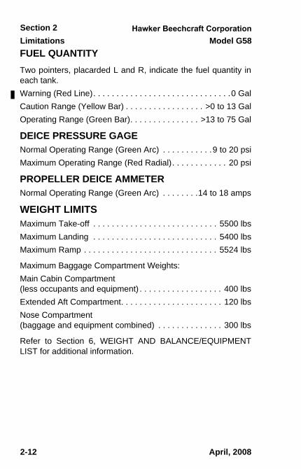
FUEL QUANTITYTwo pointers, placarded L and R, indicate the fuel quantity ineach tank.Warning (Red Line). . . . . . . . . . . . . . . . . . . . . . . . . . . . . .0 GalCaution Range (Yellow Bar) . . . . . . . . . . . . . . . . . >0 to 13 GalOperating Range (Green Bar). . . . . . . . . . . . . . . >13 to 75 Gal
DEICE PRESSURE GAGENormal Operating Range (Green Arc) . . . . . . . . . . .9 to 20 psiMaximum Operating Range (Red Radial). . . . . . . . . . . . 20 psi
PROPELLER DEICE AMMETERNormal Operating Range (Green Arc) . . . . . . . .14 to 18 amps
WEIGHT LIMITSMaximum Take-off . . . . . . . . . . . . . . . . . . . . . . . . . . . 5500 lbsMaximum Landing . . . . . . . . . . . . . . . . . . . . . . . . . . . 5400 lbsMaximum Ramp . . . . . . . . . . . . . . . . . . . . . . . . . . . . . 5524 lbs
Maximum Baggage Compartment Weights: Main Cabin Compartment(less occupants and equipment) . . . . . . . . . . . . . . . . . . 400 lbsExtended Aft Compartment. . . . . . . . . . . . . . . . . . . . . . 120 lbsNose Compartment (baggage and equipment combined) . . . . . . . . . . . . . . 300 lbs
Refer to Section 6, WEIGHT AND BALANCE/EQUIPMENTLIST for additional information.
April, 2008
sec02.fm Page 12 Thursday, May 1, 2008 2:15 PM
LimitationsSection 2
Model G58
2-13
Document Date
2-13
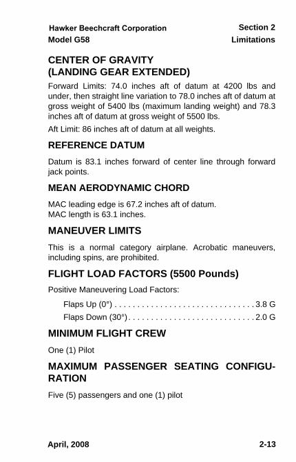
CENTER OF GRAVITY (LANDING GEAR EXTENDED) Forward Limits: 74.0 inches aft of datum at 4200 lbs andunder, then straight line variation to 78.0 inches aft of datum atgross weight of 5400 lbs (maximum landing weight) and 78.3inches aft of datum at gross weight of 5500 lbs. Aft Limit: 86 inches aft of datum at all weights.
REFERENCE DATUM Datum is 83.1 inches forward of center line through forwardjack points.
MEAN AERODYNAMIC CHORD MAC leading edge is 67.2 inches aft of datum. MAC length is 63.1 inches.
MANEUVER LIMITS This is a normal category airplane. Acrobatic maneuvers,including spins, are prohibited.
FLIGHT LOAD FACTORS (5500 Pounds) Positive Maneuvering Load Factors:
Flaps Up (0°) . . . . . . . . . . . . . . . . . . . . . . . . . . . . . . . 3.8 GFlaps Down (30°) . . . . . . . . . . . . . . . . . . . . . . . . . . . . 2.0 G
MINIMUM FLIGHT CREW One (1) Pilot
MAXIMUM PASSENGER SEATING CONFIGU-RATION Five (5) passengers and one (1) pilot
April, 2008
sec02.fm Page 13 Thursday, May 1, 2008 2:15 PM
Limitations Model G58Section 2
2 - 14
Document Date
2-14
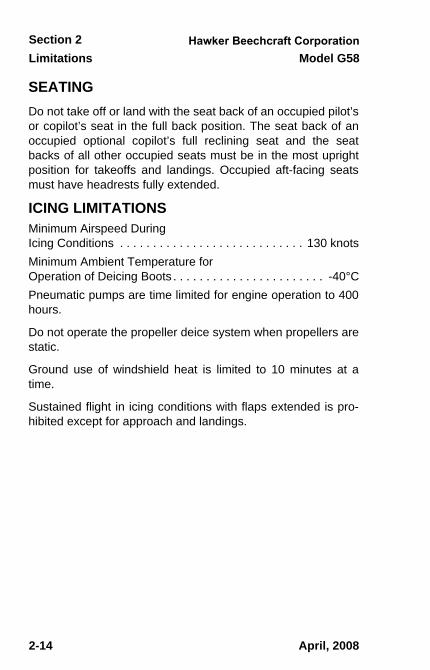
SEATING Do not take off or land with the seat back of an occupied pilot’sor copilot’s seat in the full back position. The seat back of anoccupied optional copilot’s full reclining seat and the seatbacks of all other occupied seats must be in the most uprightposition for takeoffs and landings. Occupied aft-facing seatsmust have headrests fully extended.
ICING LIMITATIONS Minimum Airspeed DuringIcing Conditions . . . . . . . . . . . . . . . . . . . . . . . . . . . . 130 knotsMinimum Ambient Temperature forOperation of Deicing Boots . . . . . . . . . . . . . . . . . . . . . . . -40°CPneumatic pumps are time limited for engine operation to 400hours.
Do not operate the propeller deice system when propellers arestatic.
Ground use of windshield heat is limited to 10 minutes at atime.
Sustained flight in icing conditions with flaps extended is pro-hibited except for approach and landings.
April, 2008
sec02.fm Page 14 Thursday, May 1, 2008 2:15 PM
LimitationsSection 2
Model G58
2-15
Document Date
2-15
LIMITATIONS WHEN ENCOUNTERING SEVEREICING CONDITIONS (Required By FAA AD 98-04-24)
Severe icing may result from environmentalconditions outside of those for which theairplane is certificated. Flight in freezingrain, freezing drizzle, or mixed icing condi-tions (supercooled liquid water and icecrystals) may result in ice build-up on pro-tected surfaces exceeding the capability ofthe ice protection system, or may result inice forming aft of the protected surfaces.This ice may not be shed using the ice pro-tection systems, and may seriouslydegrade the performance and controllabilityof the airplane.
1. During flight, severe icing conditions that exceed thosefor which the airplane is certificated shall be determinedby the following visual cues. If one or more of thesevisual cues exists, immediately request priority handlingfrom Air Traffic Control to facilitate a route or an altitudechange to exit the icing conditions. a. Unusually extensive ice accumulation on the airframe
and windshield in areas not normally observed to col-lect ice.
b. Accumulation of ice on the upper surface of the wing,aft of the protected area.
c. Accumulation of ice on the engine nacelles and pro-peller spinners farther aft than normally observed.
April, 2008
sec02.fm Page 15 Tuesday, February 3, 2009 8:30 AM
Limitations Model G58Section 2
2 - 16
Document Date
2-16
2. Since the autopilot, when installed and operating, maymask tactile cues that indicate adverse changes in han-dling characteristics, use of the autopilot is prohibitedwhen any of the visual cues specified above exist, orwhen unusual lateral trim requirements or autopilot trimwarnings are encountered while the airplane is in icingconditions.
3. All wing icing inspection lights must be operative prior toflight into known or forecast icing conditions at night.[NOTE: This supersedes any relief provided by the Mas-ter Minimum Equipment List (MMEL).]
AVIONICSGENERAL
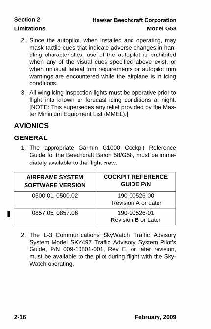
1. The appropriate Garmin G1000 Cockpit ReferenceGuide for the Beechcraft Baron 58/G58, must be imme-diately available to the flight crew.
2. The L-3 Communications SkyWatch Traffic AdvisorySystem Model SKY497 Traffic Advisory System Pilot’sGuide, P/N 009-10801-001, Rev E, or later revision,must be available to the pilot during flight with the Sky-Watch operating.
AIRFRAME SYSTEM SOFTWARE VERSION
COCKPIT REFERENCE GUIDE P/N
0500.01, 0500.02 190-00526-00 Revision A or Later
0857.05, 0857.06 190-00526-01Revision B or Later
February, 2009
sec02.fm Page 16 Tuesday, February 3, 2009 8:30 AM
LimitationsSection 2
Model G58
2-17
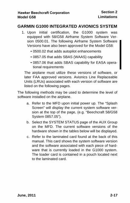
GARMIN G1000 INTEGRATED AVIONICS SYSTEM1. Upon initial certification, the G1000 system was
equipped with 58/G58 Airframe System Software Ver-sion 0500.01. The following Airframe System SoftwareVersions have also been approved for the Model G58:
• 0500.02 that adds autopilot enhancements• 0857.05 that adds SBAS (WAAS) capability• 0857.06 that adds SBAS capability for EASA opera-
tional requirementsThe airplane must utilize these versions of software, orlater FAA approved versions. Avionics Line ReplaceableUnits (LRUs) associated with each version of software arelisted on the following pages.
The following methods may be used to determine the level ofsoftware installed on the airplane.
a. Refer to the MFD upon initial power up. The “SplashScreen” will display the current system software ver-sion at the top of the page, (e.g. “Beechcraft 58/G58System 0857.05”).
b. Select the SYSTEM STATUS page of the AUX Groupon the MFD. The current software versions of thehardware shown in the tables below will be displayed.
c. Refer to the laminated card found at the back of thismanual. This card shows the system software versionand the software associated with each piece of hard-ware that is currently loaded in the G1000 system.The loader card is contained in a pouch located nextto the laminated card.
June, 2011
58-590000-67A8_sec02.fm Page 17 Wednesday, May 11, 2011 3:49 PM
Limitations Model G58Section 2
2-18
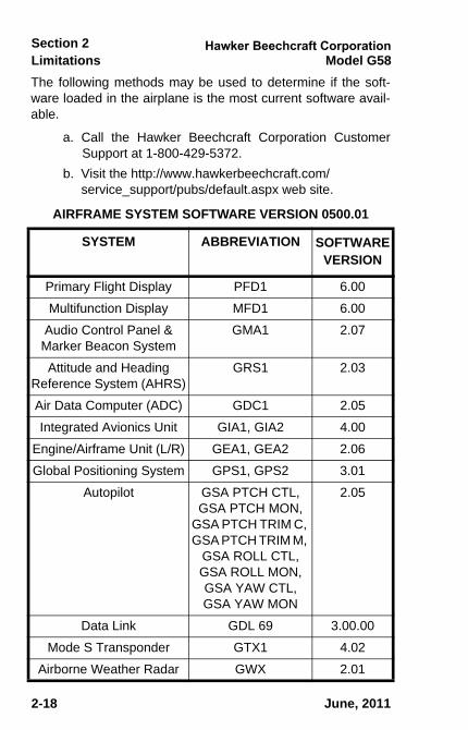
The following methods may be used to determine if the soft-ware loaded in the airplane is the most current software avail-able.
a. Call the Hawker Beechcraft Corporation CustomerSupport at 1-800-429-5372.
b. Visit the http://www.hawkerbeechcraft.com/service_support/pubs/default.aspx web site.
AIRFRAME SYSTEM SOFTWARE VERSION 0500.01
SYSTEM ABBREVIATION SOFTWAREVERSION
Primary Flight Display PFD1 6.00
Multifunction Display MFD1 6.00
Audio Control Panel &Marker Beacon System
GMA1 2.07
Attitude and HeadingReference System (AHRS)
GRS1 2.03
Air Data Computer (ADC) GDC1 2.05
Integrated Avionics Unit GIA1, GIA2 4.00
Engine/Airframe Unit (L/R) GEA1, GEA2 2.06
Global Positioning System GPS1, GPS2 3.01
Autopilot GSA PTCH CTL, GSA PTCH MON,
GSA PTCH TRIM C, GSA PTCH TRIM M,
GSA ROLL CTL, GSA ROLL MON, GSA YAW CTL, GSA YAW MON
2.05
Data Link GDL 69 3.00.00
Mode S Transponder GTX1 4.02
Airborne Weather Radar GWX 2.01
June, 2011
58-590000-67A8_sec02.fm Page 18 Wednesday, May 11, 2011 3:49 PM
LimitationsSection 2
Model G58
2-19
Document Date
2-19
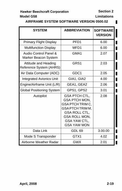
AIRFRAME SYSTEM SOFTWARE VERSION 0500.02
SYSTEM ABBREVIATION SOFTWAREVERSION
Primary Flight Display PFD1 6.00
Multifunction Display MFD1 6.00
Audio Control Panel &Marker Beacon System
GMA1 2.07
Attitude and HeadingReference System (AHRS)
GRS1 2.03
Air Data Computer (ADC) GDC1 2.05
Integrated Avionics Unit GIA1, GIA2 4.00
Engine/Airframe Unit (L/R) GEA1, GEA2 2.06
Global Positioning System GPS1, GPS2 3.01
Autopilot GSA PTCH CTL, GSA PTCH MON,
GSA PTCH TRIM C, GSA PTCH TRIM M,
GSA ROLL CTL, GSA ROLL MON, GSA YAW CTL, GSA YAW MON
2.08
Data Link GDL 69 3.00.00
Mode S Transponder GTX1 4.02
Airborne Weather Radar GWX 2.01
April, 2008
sec02.fm Page 19 Tuesday, February 3, 2009 8:30 AM
Limitations Model G58Section 2
2 - 20
Document Date
2-20
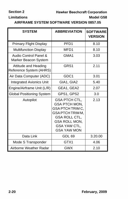
AIRFRAME SYSTEM SOFTWARE VERSION 0857.05
SYSTEM ABBREVIATION SOFTWAREVERSION
Primary Flight Display PFD1 8.10
Multifunction Display MFD1 8.10
Audio Control Panel &Marker Beacon System
GMA1 3.03
Attitude and HeadingReference System (AHRS)
GRS1 2.11
Air Data Computer (ADC) GDC1 3.01
Integrated Avionics Unit GIA1, GIA2 5.40
Engine/Airframe Unit (L/R) GEA1, GEA2 2.07
Global Positioning System GPS1, GPS2 3.0
Autopilot GSA PTCH CTL, GSA PTCH MON,
GSA PTCH TRIM C, GSA PTCH TRIM M,
GSA ROLL CTL, GSA ROLL MON, GSA YAW CTL, GSA YAW MON
2.13
Data Link GDL 69 3.20.00
Mode S Transponder GTX1 4.06
Airborne Weather Radar GWX 2.10
February, 2009
sec02.fm Page 20 Tuesday, February 3, 2009 8:30 AM
LimitationsSection 2
Model G58
2-21
Document Date
2-21
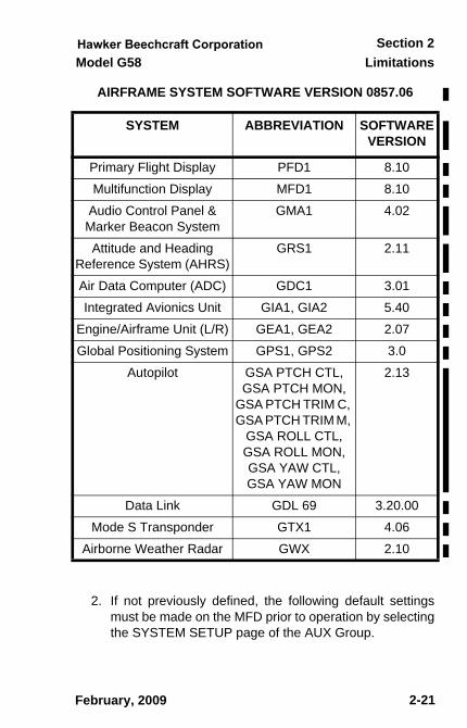
AIRFRAME SYSTEM SOFTWARE VERSION 0857.06
2. If not previously defined, the following default settingsmust be made on the MFD prior to operation by selectingthe SYSTEM SETUP page of the AUX Group.
SYSTEM ABBREVIATION SOFTWAREVERSION
Primary Flight Display PFD1 8.10
Multifunction Display MFD1 8.10
Audio Control Panel &Marker Beacon System
GMA1 4.02
Attitude and HeadingReference System (AHRS)
GRS1 2.11
Air Data Computer (ADC) GDC1 3.01
Integrated Avionics Unit GIA1, GIA2 5.40
Engine/Airframe Unit (L/R) GEA1, GEA2 2.07
Global Positioning System GPS1, GPS2 3.0
Autopilot GSA PTCH CTL, GSA PTCH MON,
GSA PTCH TRIM C, GSA PTCH TRIM M,
GSA ROLL CTL, GSA ROLL MON, GSA YAW CTL, GSA YAW MON
2.13
Data Link GDL 69 3.20.00
Mode S Transponder GTX1 4.06
Airborne Weather Radar GWX 2.10
February, 2009
sec02.fm Page 21 Tuesday, December 15, 2009 8:29 AM
Limitations Model G58Section 2
2 - 22
Document Date
2-22
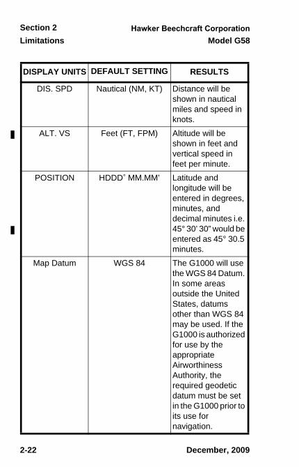
DISPLAY UNITS DEFAULT SETTING RESULTS
DIS. SPD Nautical (NM, KT) Distance will be shown in nautical miles and speed in knots.
ALT. VS Feet (FT, FPM) Altitude will be shown in feet and vertical speed in feet per minute.
POSITION HDDD° MM.MM’ Latitude and longitude will be entered in degrees, minutes, and decimal minutes i.e. 45° 30’ 30” would be entered as 45° 30.5 minutes.
Map Datum WGS 84 The G1000 will use the WGS 84 Datum. In some areas outside the United States, datums other than WGS 84 may be used. If the G1000 is authorized for use by the appropriate Airworthiness Authority, the required geodetic datum must be set in the G1000 prior to its use for navigation.
December, 2009
sec02.fm Page 22 Tuesday, December 15, 2009 8:29 AM
LimitationsSection 2
Model G58
2-23
3. Use of the VOR/ILS receiver to fly approaches notapproved for GPS require VOR/ILS navigation data to bevalid on the PFD display.
4. Fuel Planning information found on the MFD by selectingthe TRIP PLANNING page of the AUX Group are advi-sory only and do not replace the primary fuel quantityand fuel flow displays on the PFD.
5. The temperature limit of the G1000 system is -40° C.The temperature of the PFD and MFD must be -20° C orabove to function properly.
6. Viewability of the PFD and MFD displays may bedegraded when wearing polarized sunglasses.
7. For Airframe System Software Version 0500.01 or0500.02, do not load a new arrival or departure proce-dure in the flight plan if one currently exists without firstremoving the existing arrival or departure procedure.Failing to observe this limitation can cause deviationindications, loss of GPS navigation information, andother display anomalies. If display anomalies are notedafter editing the flight plan, perform either a direct to oractivate leg operation as appropriate on the flight plan toensure correct flight plan sequencing and guidance.
GPS NAVIGATION
1. Navigation is based upon use of only the Global Posi-tioning System (GPS) operated by the United States ofAmerica.
2. Navigational information is referenced to the World Geo-detic System 1984 (WGS-84), and must only be usedwith aeronautical information (electronic data and aero-nautical charts) which conforms to WGS-84, or equiva-lent. Operations in areas outside of the United Stateswhich use datums other than WGS-84 are approvedwhen authorized by the appropriate AirworthinessAuthority. In such cases the required geodetic datummust be set in the G1000 prior to its use for navigation.
June, 2011
58-590000-67A8_sec02.fm Page 23 Monday, May 16, 2011 8:49 AM
Limitations Model G58Section 2
2-24
3. Navigation using the GPS system is prohibited unlessthe pilot verifies the currency of the Aviation Database orverifies each selected waypoint for accuracy by refer-ence to current approved data. The Aviation Databaseversion is displayed on the MFD power-up page immedi-ately after system power-up and must be acknowledged.
4. Provided the Garmin G1000 GPS receivers are receiv-ing adequate and usable GPS signals, it has been dem-onstrated capable of and meets the accuracyspecifications for the following:a. VFR/IFR enroute, oceanic, and terminal operations
within the U.S. National Airspace System in accor-dance with AC 20-138A.
b. VFR/IFR non-precision instrument approach opera-tions within the U.S. National Airspace System inaccordance with AC 20-138A, including “GPS”, “orGPS”, and “RNAV(GPS)” approaches.
c. VFR/IFR operations on Standard Instrument Depar-tures (SIDs) (RNAV 1) and Standard InstrumentArrivals (STARs) (RNAV 1) in accordance with AC90-100.
d. VFR/IFR Oceanic and Remote operations in accor-dance with Appendix 1 of AC 20-138A. A Garmin Pre-diction Program, or equivalent, must have been runwith satisfactory results. This does not constitute anoperational approval.
e. Operation in European B-RNAV airspace is accor-dance with AC 90-96, AC 20-138A, and JAA tempo-rary Guidance Material, Leaflet No. 2, Rev. 1. Thisdoes not constitute an operational approval.
f. Operations up to 70° North and 70° South Latitudesexcept as follows:1) Operations North of 65° Latitude are prohibited
between 75° West and 120° West Longitude.
February, 2009
58-590000-67A8_sec02.fm Page 24 Monday, May 16, 2011 8:49 AM
Model G58 Baron
P/N 58-590000-67TC23 of 4
LIMITATIONS
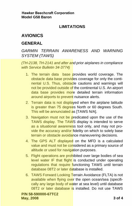
AVIONICSGENERALGARMIN TERRAIN AWARENESS AND WARNINGSYSTEM (TAWS)
(TH-2138, TH-2141 and after and prior airplanes in compliancewith Service Bulletin 34-3774)
1. The terrain data base provides world coverage. Theobstacle data base provides coverage for only the conti-nental U.S. Thus, obstacle cautions and warnings willnot be provided outside of the continental U.S. An airportdata base provides more detailed terrain informationaround airports to prevent nuisance alerts.
2. Terrain data is not displayed when the airplane latitudeis greater than 75 degrees North or 60 degrees South.This will be annunciated as [TAWS N/A].
3. Navigation must not be predicated upon the use of theTAWS display. The TAWS display is intended to serveas a situational awareness tool only, and may not pro-vide the accuracy and/or fidelity on which to solely baseterrain or obstacle avoidance maneuvering decisions.
4. The GPS ALT displayed on the MFD is a calculatedvalue and must not be considered as a primary source ofaltitude or used for navigation purposes.
5. Flight operations are prohibited over large bodies of sealevel water IF that flight is conducted under operatingregulations that require functioning TAWS until terraindatabase 08T2 or later database is installed.
6. TAWS Forward Looking Terrain Avoidance (FLTA) is notavailable when flying over the open ocean/sea (specifi-cally any large body of water at sea level) until database08T2 or later database is installed. Do not use TAWS
May, 2008
TC2.fm Page 3 Wednesday, May 21, 2008 10:14 AM

Model G58 Baron
P/N 58-590000-67TC24 of 4
information for primary terrain avoidance. TAWS isintended only to enhance situational awareness.
May, 2008
TC2.fm Page 4 Wednesday, May 21, 2008 10:14 AM
LimitationsSection 2
Model G58
2-25
2) Operations South of 55° Latitude are prohibitedbetween 120° East and 165° East Longitude.
5. Instrument approaches must be accomplished in accor-dance with approved instrument approach proceduresthat are retrieved from the GPS database. The GPSdatabase must incorporate the current update cycle orbe verified for accuracy using current approved naviga-tion data.
6. Instrument approaches must be conducted in the GPSapproach mode and Receiver Autonomous IntegrityMonitoring (RAIM) must be available at the FinalApproach Fix.
7. Accomplishment of ILS, LOC, LOC-BC, LDA, SDF, MLSor any other type of approach not approved for GPSoverlay with the GPS receiver is not authorized.
8. When an alternate airport is required by the applicableoperating rules, it must be served by an approach basedon other than GPS navigation, the airplane must havethe operational equipment capable of using that naviga-tion aid, and the required navigation aid must be opera-tional.
9. Airplanes equipped with Airframe System Software Ver-sion 0857.05 or 0857.06 are approved for approach pro-cedures with vertical guidance including LPV, L/VNAVand LNAV+V, within the U.S. National Airspace System.
10. Airplanes not equipped with Baro VNAV:VNAV information may be utilized for advisory informa-tion only. Use of VNAV information for InstrumentApproach Procedures does not guarantee step-down fixaltitude protection, or arrival at approach minimums in anormal position to land. VNAV also does not guaranteecompliance with intermediate altitude constraintsbetween the top of descent and the waypoint where theVNAV path terminates in terminal or enroute operations.
June, 2011
58-590000-67A8_sec02.fm Page 25 Monday, May 16, 2011 8:49 AM
Limitations Model G58Section 2
2-26
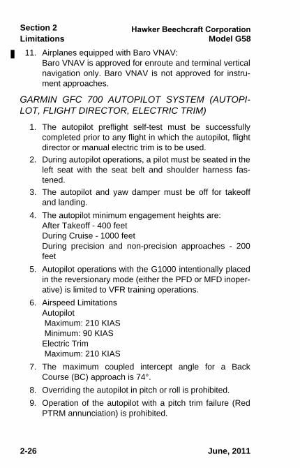
11. Airplanes equipped with Baro VNAV:Baro VNAV is approved for enroute and terminal verticalnavigation only. Baro VNAV is not approved for instru-ment approaches.
GARMIN GFC 700 AUTOPILOT SYSTEM (AUTOPI-LOT, FLIGHT DIRECTOR, ELECTRIC TRIM)
1. The autopilot preflight self-test must be successfullycompleted prior to any flight in which the autopilot, flightdirector or manual electric trim is to be used.
2. During autopilot operations, a pilot must be seated in theleft seat with the seat belt and shoulder harness fas-tened.
3. The autopilot and yaw damper must be off for takeoffand landing.
4. The autopilot minimum engagement heights are:After Takeoff - 400 feet During Cruise - 1000 feetDuring precision and non-precision approaches - 200feet
5. Autopilot operations with the G1000 intentionally placedin the reversionary mode (either the PFD or MFD inoper-ative) is limited to VFR training operations.
6. Airspeed LimitationsAutopilot Maximum: 210 KIAS Minimum: 90 KIASElectric Trim Maximum: 210 KIAS
7. The maximum coupled intercept angle for a BackCourse (BC) approach is 74°.
8. Overriding the autopilot in pitch or roll is prohibited.9. Operation of the autopilot with a pitch trim failure (Red
PTRM annunciation) is prohibited.
June, 2011
58-590000-67A8_sec02.fm Page 26 Monday, May 16, 2011 8:49 AM
LimitationsSection 2
Model G58
2-27
10. The autopilot system is only approved for Category I ILSapproaches and non-precision approaches.
11. Airplanes with Airframe Software Version 0500.01 or0500.02:When conducting GPS assisted intercepts of ILS finalapproach courses with the autopilot engaged, the ILSCDI Capture mode on the Systems Setup page of theAuxiliary Page Group must be set to Manual.
12. Maximum fuel imbalance with autopilot engaged is 15GAL (~ 90 lbs).
L-3 COMMUNICATIONS SKYWATCH SKY497TRAFFIC ADVISORY SYSTEM (if installed)
1. The pilot must not maneuver the airplane based only onthe traffic display. The traffic display is intended to assistin visually locating traffic and lacks the resolution neces-sary for use in evasive maneuvering.
2. If the pilot is advised by Air Traffic Control to disable thealtitude reporting function of the transponder, the TrafficAdvisory System must be placed in Standby.
WEATHER RADAR
The area within the scan arc and within 11feet of an operating GWX 68 system can bea hazardous area. Do not operate the sys-tem in any mode other than STANDBYwhen the antenna might scan over person-nel within range. Turning the transmitter onwhile inside the hangar is not advisable.
June, 2011
58-590000-67A8_sec02.fm Page 27 Monday, May 16, 2011 8:49 AM
Limitations Model G58Section 2
2-28
GARMIN TERRAIN AWARENESS AND WARNINGSYSTEM (TAWS)
(TH-2138, TH-2141 and after and prior airplanes in compliancewith Service Bulletin 34-3774.)
1. The terrain database provides world coverage. Theobstacle database provides coverage for only the conti-nental U.S. Thus, obstacle cautions and warnings willnot be provided outside of the continental U.S. An Air-port database provides more detailed terrain informationaround airports to prevent nuisance alerts.
2. Terrain data is not displayed when the airplane latitudeis greater than 75 degrees North or 60 degrees South.This will be annunciated as [TAWS N/A].
3. Navigation must not be predicated upon the use of theTAWS display. The TAWS Display is intended to serveas a situational awareness tool only, and may not pro-vide the accuracy and/or fidelity on which to solely baseterrain or obstacle avoidance maneuvering decisions.
4. The GPS ALT displayed on the MFD is a calculatedvalue and must not be considered as a primary source ofaltitude or used for navigation purposes.
February, 2009
58-590000-67A8_sec02.fm Page 28 Monday, May 16, 2011 8:49 AM
LimitationsSection 2
Model G58
2-29
Document Date
2-29
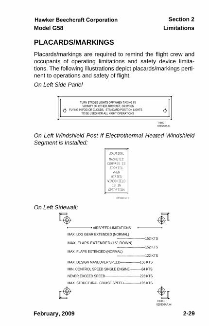
PLACARDS/MARKINGSPlacards/markings are required to remind the flight crew andoccupants of operating limitations and safety device limita-tions. The following illustrations depict placards/markings perti-nent to operations and safety of flight.On Left Side Panel
On Left Windshield Post If Electrothermal Heated WindshieldSegment is Installed:
On Left Sidewall:
TH00C 020329AA.AI
TURN STROBE LIGHTS OFF WHEN TAXING IN VICINITY OF OTHER AIRCRAFT, OR WHEN
FLYING IN FOG OR CLOUDS. STANDARD POSITION LIGHTS TO BE USED FOR ALL NIGHT OPERATIONS
MAX. STRUCTURAL CRUISE SPEED---------------195 KTS
NEVER EXCEED SPEED--------------------------------223 KTS
MIN. CONTROL SPEED SINGLE ENGINE-----------84 KTS
MAX. DESIGN MANEUVER SPEED------------------156 KTS
MAX. FLAPS EXTENDED (NORMAL)--------------------------152 KTS
--------------------------122 KTS
--------------------------152 KTSMAX. LDG GEAR EXTENDED (NORMAL)
AIRSPEED LIMITATIONS
TH00C 020330AA.AI
February, 2009
sec02.fm Page 29 Tuesday, February 3, 2009 8:30 AM
Limitations Model G58Section 2
2 - 30
Document Date
2-30
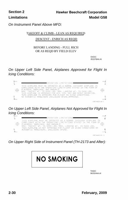
On Instrument Panel Above MFD:
On Upper Left Side Panel, Airplanes Approved for Flight InIcing Conditions:
On Upper Left Side Panel, Airplanes Not Approved for Flight InIcing Conditions:
On Upper Right Side of Instrument Panel (TH-2173 and After):
E#02C 051578AA.AI
TH02C 063324AA.AI
February, 2009
sec02.fm Page 30 Tuesday, February 3, 2009 8:30 AM
LimitationsSection 2
Model G58
2-31
Document Date
2-31
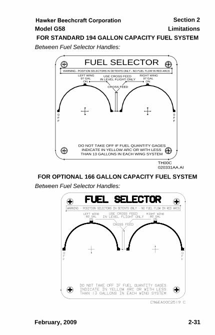
FOR STANDARD 194 GALLON CAPACITY FUEL SYSTEMBetween Fuel Selector Handles:
FOR OPTIONAL 166 GALLON CAPACITY FUEL SYSTEM Between Fuel Selector Handles:
FF0
FF0
FUEL SELECTOR
CROSS FEED
IN LEVEL FLIGHT ONLYUSE CROSS FEEDLEFT WING
97 GAL ON
RIGHT WING 97 GAL
ON
TH00C 020331AA.AI
DO NOT TAKE OFF IF FUEL QUANTITY GAGES INDICATE IN YELLOW ARC OR WITH LESS THAN 13 GALLONS IN EACH WING SYSTEM
February, 2009
sec02.fm Page 31 Tuesday, February 3, 2009 8:30 AM
Limitations Model G58Section 2
2 - 32
Document Date
2-32
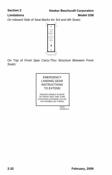
On Inboard Side of Seat Backs for 3rd and 4th Seats:
On Top of Front Spar Carry-Thru Structure Between FrontSeats:
TH02C 000396AA.AI
EMERGENCY LANDING GEAR INSTRUCTIONS
TO EXTEND
ENGAGE HANDLE IN REAR OF FRONT SEAT AND TURN
COUNTERCLOCKWISE AS FAR AS POSSIBLE (50 TURNS)
February, 2009
sec02.fm Page 32 Tuesday, February 3, 2009 8:30 AM
LimitationsSection 2
Model G58
2-33
Document Date
2-33
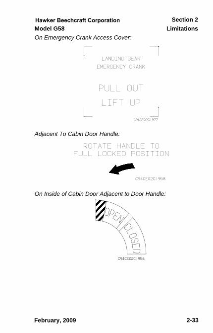
On Emergency Crank Access Cover:
Adjacent To Cabin Door Handle:
On Inside of Cabin Door Adjacent to Door Handle:
February, 2009
sec02.fm Page 33 Tuesday, February 3, 2009 8:30 AM
Limitations Model G58Section 2
2 - 34
Document Date
2-34
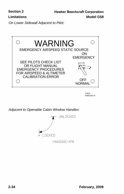
On Lower Sidewall Adjacent to Pilot:
Adjacent to Openable Cabin Window Handles:
TH02C 060621AA.AI
WARNINGEMERGENCY AIRSPEED STATIC SOURCE
SEE PILOTS CHECK LISTOR FLIGHT MANUAL
ONEMERGENCY
OFFNORMAL
EMERGENCY PROCEDURESFOR AIRSPEED & ALTIMETER
CALIBRATION ERROR
February, 2009
sec02.fm Page 34 Tuesday, February 3, 2009 8:30 AM
LimitationsSection 2
Model G58
2-35
Document Date
2-35
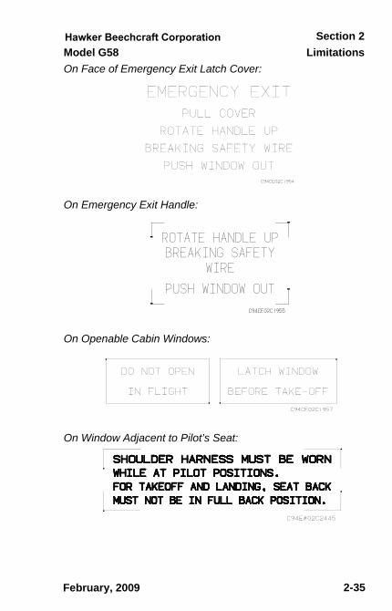
On Face of Emergency Exit Latch Cover:
On Emergency Exit Handle:
On Openable Cabin Windows:
On Window Adjacent to Pilot’s Seat:
February, 2009
sec02.fm Page 35 Tuesday, February 3, 2009 8:30 AM
Limitations Model G58Section 2
2 - 36
Document Date
2-36
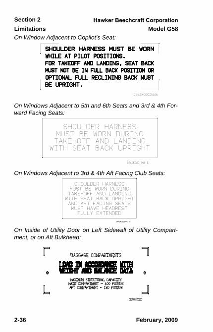
On Window Adjacent to Copilot’s Seat:
On Windows Adjacent to 5th and 6th Seats and 3rd & 4th For-ward Facing Seats:
On Windows Adjacent to 3rd & 4th Aft Facing Club Seats:
On Inside of Utility Door on Left Sidewall of Utility Compart-ment, or on Aft Bulkhead:
C95TH02C0160
February, 2009
sec02.fm Page 36 Tuesday, February 3, 2009 8:30 AM
LimitationsSection 2
Model G58
2-37
Document Date
2-37
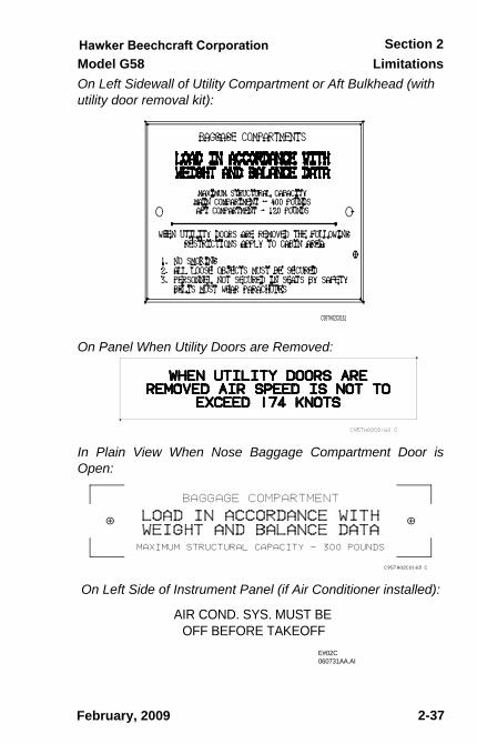
On Left Sidewall of Utility Compartment or Aft Bulkhead (with utility door removal kit):
On Panel When Utility Doors are Removed:
In Plain View When Nose Baggage Compartment Door isOpen:
On Left Side of Instrument Panel (if Air Conditioner installed):
C95TH02C0161
E#02C 060731AA.AI
AIR COND. SYS. MUST BE OFF BEFORE TAKEOFF
February, 2009
sec02.fm Page 37 Tuesday, February 3, 2009 8:30 AM
Limitations Model G58Section 2
2 - 38
Document Date
2-38
Adjacent to Oil Filler Caps:
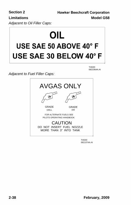
Adjacent to Fuel Filler Caps:
TH02D 082106AA.AI
TH02D 082107AA.AI
AVGAS ONLY
GRADE100LL 100
GRADE
FOR ALTERNATE FUELS SEE PILOTS OPERATING HANDBOOK
CAUTION
DO NOT INSERT FUEL NOZZLE MORE THAN 3" INTO TANK
February, 2009
sec02.fm Page 38 Tuesday, February 3, 2009 8:30 AM
LimitationsSection 2
Model G58
2-39
Document Date
2-39
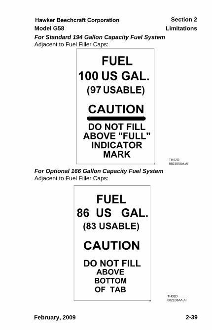
For Standard 194 Gallon Capacity Fuel SystemAdjacent to Fuel Filler Caps:
For Optional 166 Gallon Capacity Fuel SystemAdjacent to Fuel Filler Caps:
TH02D 082105AA.AI
TH02D 082103AA.AI
February, 2009
sec02.fm Page 39 Tuesday, February 3, 2009 8:30 AM
Limitations Model G58Section 2
2 - 40
Document Date
2-40
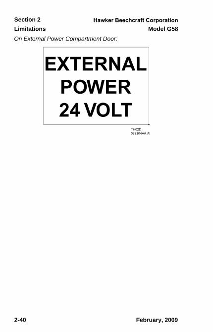
On External Power Compartment Door:
TH02D 082104AA.AI
February, 2009
sec02.fm Page 40 Tuesday, February 3, 2009 8:30 AM
LimitationsSection 2
Model G58
2-41
Document Date
2-41
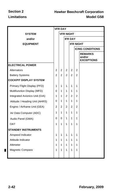
KINDS OF OPERATIONS The Model G58 is approved for the following types of opera-tions when the required equipment as shown in the KINDS OFOPERATIONS EQUIPMENT LIST, is installed and operable.
1. VFR day and night 2. IFR day and night3. Icing Conditions
KINDS OF OPERATIONS EQUIPMENT LISTThis airplane may be operated in day or night VFR, day ornight IFR, and icing conditions when the required systems andequipment are installed and operable.
The following equipment list identifies the systems and equip-ment upon which type certification for each kind of operationwas predicated. The systems and equipment listed must beinstalled and operable for the particular kind of operation indi-cated unless:
1. The airplane is approved to be operated in accordancewith a current Minimum Equipment List (MEL) issued bythe FAA.
or;
2. An alternate procedure is provided in the Pilot’s Operat-ing Handbook and FAA Approved Airplane Flight Manualfor the inoperative state of the listed system or equip-ment and all limitations are complied with.
Numbers in the Kinds of Operations Equipment List refer toquantities required to be operative for the specified condition.The list does not include all equipment that may be required byspecific operating rules. It also does not include componentsobviously required for the airplane to be airworthy, such aswings, empennage, engine, etc.
February, 2009
sec02.fm Page 41 Tuesday, February 3, 2009 8:30 AM
Limitations Model G58Section 2
2 - 42
Document Date
2-42
VFR DAY
SYSTEM VFR NIGHT
and/or IFR DAY
EQUIPMENT IFR NIGHT
ICING CONDITIONS
REMARKSand/orEXCEPTIONS
ELECTRICAL POWER
Alternators 2 2 2 2 2
Battery Systems 2 2 2 2 2
COCKPIT DISPLAY SYSTEM
Primary Flight Display (PFD) 1 1 1 1 1
Multifunction Display (MFD) 0 1 1 1 1
Integrated Avionics Unit (GIA) 1 1 2 2 2
Attitude / Heading Unit (AHRS) 0 1 1 1 1
Engine / Airframe Unit (GEA) 2 2 2 2 2
Air Data Computer (ADC) 1 1 1 1 1
Audio Panel (GMA) 0 0 1 1 1
OAT 1 1 1 1 1
STANDBY INSTRUMENTS
Airspeed Indicator 1 1 1 1 1
Attitude Indicator 1 1 1 1 1
Altimeter 1 1 1 1 1
Magnetic Compass 1 1 1 1 1
February, 2009
sec02.fm Page 42 Tuesday, February 3, 2009 8:30 AM
LimitationsSection 2
Model G58
2-43
Document Date
2-43
VFR DAY
SYSTEM VFR NIGHT
and/or IFR DAY
EQUIPMENT IFR NIGHT
ICING CONDITIONS
REMARKSand/orEXCEPTIONS
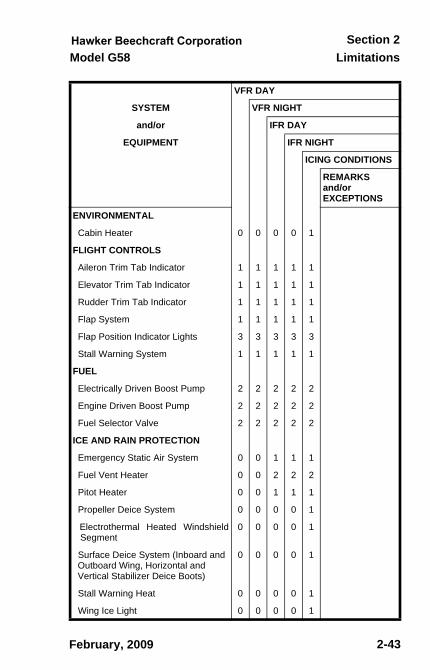
ENVIRONMENTAL
Cabin Heater 0 0 0 0 1
FLIGHT CONTROLS
Aileron Trim Tab Indicator 1 1 1 1 1
Elevator Trim Tab Indicator 1 1 1 1 1
Rudder Trim Tab Indicator 1 1 1 1 1
Flap System 1 1 1 1 1
Flap Position Indicator Lights 3 3 3 3 3
Stall Warning System 1 1 1 1 1
FUEL
Electrically Driven Boost Pump 2 2 2 2 2
Engine Driven Boost Pump 2 2 2 2 2
Fuel Selector Valve 2 2 2 2 2
ICE AND RAIN PROTECTION
Emergency Static Air System 0 0 1 1 1
Fuel Vent Heater 0 0 2 2 2
Pitot Heater 0 0 1 1 1
Propeller Deice System 0 0 0 0 1
Electrothermal Heated WindshieldSegment
0 0 0 0 1
Surface Deice System (Inboard and Outboard Wing, Horizontal and Vertical Stabilizer Deice Boots)
0 0 0 0 1
Stall Warning Heat 0 0 0 0 1
Wing Ice Light 0 0 0 0 1
February, 2009
sec02.fm Page 43 Tuesday, February 3, 2009 8:30 AM
Limitations Model G58Section 2
2 - 44
Document Date
2-44
VFR DAY
SYSTEM VFR NIGHT
and/or IFR DAY
EQUIPMENT IFR NIGHT
ICING CONDITIONS
REMARKSand/orEXCEPTIONS
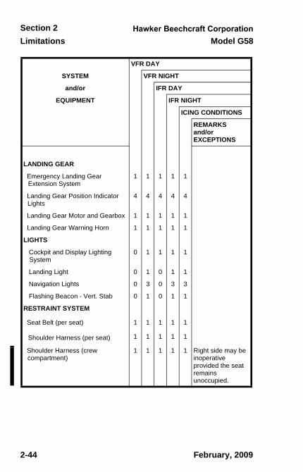
LANDING GEAR
Emergency Landing Gear Extension System
1 1 1 1 1
Landing Gear Position Indicator Lights
4 4 4 4 4
Landing Gear Motor and Gearbox 1 1 1 1 1
Landing Gear Warning Horn 1 1 1 1 1
LIGHTS
Cockpit and Display Lighting System
0 1 1 1 1
Landing Light 0 1 0 1 1
Navigation Lights 0 3 0 3 3
Flashing Beacon - Vert. Stab 0 1 0 1 1
RESTRAINT SYSTEM
Seat Belt (per seat) 1 1 1 1 1
Shoulder Harness (per seat) 1 1 1 1 1
Shoulder Harness (crew compartment)
1 1 1 1 1 Right side may be inoperative provided the seat remains unoccupied.
February, 2009
sec02.fm Page 44 Tuesday, February 3, 2009 8:30 AM