Embed Size (px)
Citation preview
BHT-407-FM-1
REISSUE — 17 DECEMBER 2002REVISION 7 — 30 JUL 2008
ROTORCRAFTFLIGHT MANUAL
THIS MANUAL SHALL BE IN THE HELICOPTER DURING ALL OPERATIONS
TYPE CERTIFICATE NO. ________
REGISTRATION NO. ______________________ SERIAL NO. ____________________
APPROVED BY DATE _____________________
DIRECTOR — AIRCRAFT CERTIFICATION BRANCHDEPARTMENT OF TRANSPORT
THE AVIATION REGULATORY AUTHORITY FOR THIS FLIGHT MANUAL IS THECANADIAN DEPARTMENT OF TRANSPORT, AIRCRAFT CERTIFICATION BRANCH.
U.S. REGISTERED HELICOPTERS ARE APPROVED BY THE FAA IN ACCORDANCE WITH THE PROVISIONS OF 14 CFR SECTION 21.29 ON
H-92
9 FEBRUARY 1996
23 FEBRUARY 1996
COPYRIGHT NOTICECOPYRIGHT 2008BELL ® HELICOPTER TEXTRON INC.AND BELL HELICOPTER TEXTRONCANADA LTD.
ALL RIGHTS RESERVED
NOTICE PAGE
Additional copies of this publication may be obtained by contacting:Commercial Publication Distribution Center
Bell Helicopter Textron Inc.P. O. Box 482
Fort Worth, Texas 76101-0482
NP———17 DEC 2002
BHT-407-FM-1
The following Warning is not applicable to helicopters on which all kits and customizinginstallations have been qualified and approved by Bell Helicopter.
WARNING
THE HELICOPTER MAY CONTAIN INSTALLATIONS, PARTS, ORPROCESSES CERTIFIED BY PARTIES OTHER THAN BELLHELICOPTER TEXTRON. BELL HELICOPTER CAN NOTCONFIRM THAT SUCH INSTALLATIONS HAVE BEEN FULLYQUALIFIED OR CONFORMED TO BELL HELICOPTER DESIGNCRITERIA. AS A RESULT OF SUCH INSTALLATIONS, BELLHELICOPTER SUPPLIED DATA MAY NOT BE VALIDCONCERNING IN-FLIGHT HANDLING QUALITIES, WEIGHT ANDBALANCE, OR HELICOPTER PERFORMANCE. IF MULTIPLE STCKITS OR SIMILAR INSTALLATIONS ARE INCORPORATED,THERE MAY BE NOT VALID TEST DATA TO QUALIFY THEHELICOPTER AS MODIFIED BY THESE INSTALLATIONS. FORREVISED DATA, CONTACT THE OWNER OF THE INSTALLEDSTC OR THE SUPPLIER FOR THE APPLICABLE APPROVAL OFEACH INSTALLATION.
30 JUL 2008—Rev. 7———A/B
BHT-407-FM-1
LOG OF PAGES
REVISION REVISIONNO. NO.PAGE PAGE
NOTE
Revised text is indicated by a black vertical line. Insert latest revision pages; dispose of superseded pages.
Original ......................0 ......................09 FEB 96Revision.....................1 .....................08 MAR 96Revision.....................2 .....................09 MAY 96Revision.....................3 ...................... 30 JUL 96Revision.....................4 ..................... 04 NOV 96Revision.....................5 ......................24 JUN 97Revision.....................6 ...................... 03 JUL 98Revision.....................7 ......................04 SEP 98Revision.....................8 ..................... 17 APR 00
Reissue ..................... 0 ......................17 DEC 02Revision .................... 1 ..................... 10 MAR 04Revision .................... 2 ......................29 NOV 04Revision .................... 3 ......................26 APR 05Revision .................... 4 ...................... 29 JUN 05Revision .................... 5 ...................... 19 FEB 07Revision .................... 6 ...................... 20 JUN 07Revision .................... 7 .......................30 JUL 08
Cover............................................................ 0Title .............................................................. 7NP................................................................. 0A/B................................................................ 7C/D................................................................ 7E/F ................................................................ 7i – ii............................................................... 0iii/iv............................................................... 01-1 – 1-3 .......................................................51-4 – 1-8 .......................................................71-9 – 1-13 ..................................................... 01-14............................................................... 51-15............................................................... 71-16 – 1-17 ................................................... 01-18 – 1-19 ................................................... 71-20............................................................... 32-1/2-2 .......................................................... 62-3 – 2-7 .......................................................52-8 – 2-9 .......................................................72-10 – 2-11 ................................................... 5
2-12 – 2-15................................................... 62-16 .............................................................. 72-17/2-18...................................................... 03-1/3-2.......................................................... 73-3 ................................................................ 73-4 – 3-8....................................................... 03-9 ................................................................ 73-10 – 3-12................................................... 03-13 .............................................................. 53-14 – 3-17................................................... 03-18 – 3-19................................................... 53-20 .............................................................. 04-1/4-2.......................................................... 04-3 – 4-50..................................................... 04-51/4-52...................................................... 05-1 – 5-18..................................................... 05-19/5-20...................................................... 0A-1/A-2......................................................... 5A-3 – A-4...................................................... 5A-5/A-6......................................................... 5
LOG OF REVISIONS

APPROVED DATE
CHIEF, FLIGHT TESTFORDIRECTOR — AIRCRAFT CERTIFICATIONTRANSPORT CANADA
30 JUL 2008—Rev. 7———C/D
BHT-407-FM-1
Original ..................... 0...................... 09 FEB 96Revision .................... 1..................... 08 MAR 96Revision .................... 2......................09 MAY 96Revision .................... 3.......................30 JUL 96Revision .................... 4......................04 NOV 96Revision .................... 5...................... 24 JUN 97Revision .................... 6.......................03 JUL 98Revision .................... 7...................... 04 SEP 98Revision .................... 8...................... 17 APR 00
Reissue......................0 ..................... 17 DEC 02Revision ....................1 .....................10 MAR 04Revision ....................2 ..................... 29 NOV 04Revision ....................3 ..................... 26 APR 05Revision ....................4 ......................29 JUN 05Revision ....................5 ......................19 FEB 07Revision ....................6 ......................20 JUN 07Revision ....................7 ...................... 30 JUL 08
LOG OF TC APPROVED REVISIONS

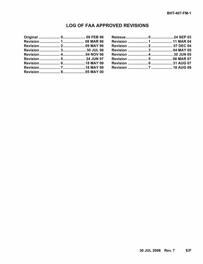
LOG OF FAA APPROVED REVISIONS
Original ..................... 0...................... 09 FEB 96Revision .................... 1..................... 08 MAR 96Revision .................... 2......................09 MAY 96Revision .................... 3.......................30 JUL 96Revision .................... 4......................04 NOV 96Revision .................... 5...................... 24 JUN 97Revision .................... 6......................18 MAY 99Revision .................... 7......................18 MAY 99Revision .................... 8......................05 MAY 00
Reissue......................0 ......................24 SEP 03Revision ....................1 .....................11 MAR 04Revision ....................2 ..................... 07 DEC 04Revision ....................3 ..................... 04 MAY 05Revision ....................4 ......................30 JUN 05Revision ....................5 .....................08 MAR 07Revision ....................6 ..................... 31 AUG 07Revision ....................7 ..................... 18 AUG 08
30 JUL 2008—Rev. 7———E/F
BHT-407-FM-1

TC APPROVED BHT-407-FM-1
19 FEB 2007—Rev. 5———1-3
Section 1LIMITATIONS
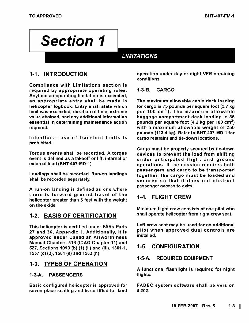
11-1. INTRODUCTION
Compliance with Limitations section isrequired by appropriate operating rules.Anytime an operating limitation is exceeded,an appropr iate entry shal l be made inhelicopter logbook. Entry shall state whichlimit was exceeded, duration of time, extremevalue attained, and any additional informationessential in determining maintenance actionrequired.
In ten t iona l use o f t rans ient l imi ts isprohibited.
Torque events shall be recorded. A torqueevent is defined as a takeoff or lift, internal orexternal load (BHT-407-MD-1).
Landings shall be recorded. Run-on landingsshall be recorded separately.
A run-on landing is defined as one wherethere is fo rward ground t rave l o f thehelicopter greater than 3 feet with the weighton the skids.
1-2. BASIS OF CERTIFICATION
This helicopter is certified under FARs Parts27 and 36, Appendix J. Additionally, it isapproved under Canadian AirworthinessManual Chapters 516 (ICAO Chapter 11) and527, Sections 1093 (b) (1) (ii) and (iii), 1301-1,1557 (c) (3), 1581 (e) and 1583 (h).
1-3. TYPES OF OPERATION
1-3-A. PASSENGERS
Basic configured helicopter is approved forseven place seating and is certified for land
operation under day or night VFR non-icingconditions.
1-3-B. CARGO
The maximum allowable cabin deck loadingfor cargo is 75 pounds per square foot (3.7 kgper 100 cm2). The maximum al lowablebaggage compartment deck loading is 86pounds per square foot (4.2 kg per 100 cm2)with a maximum allowable weight of 250pounds (113.4 kg). Refer to BHT-407-MD-1 forcargo restraint and tie-down locations.
Cargo must be properly secured by tie-downdevices to prevent the load from shiftingunder ant ic ipated f l igh t and g roundoperations. If the mission requires bothpassengers and cargo to be transportedtogether, the cargo must be loaded andsecured so tha t i t does no t obs t ructpassenger access to exits.
1-4. FLIGHT CREW
Minimum flight crew consists of one pilot whoshall operate helicopter from right crew seat.
Left crew seat may be used for an additionalpi lot when approved dual controls areinstalled.
1-5. CONFIGURATION
1-5-A. REQUIRED EQUIPMENT
A functional flashlight is required for nightflights.
FADEC system software shall be version5.202.
BHT-407-FM-1 TC APPROVED
1-4———Rev. 7—30 JUL 2008
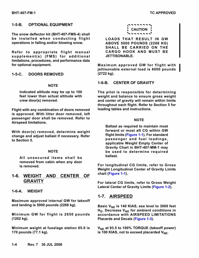
1-5-B. OPTIONAL EQUIPMENT
The snow deflector kit (BHT-407-FMS-4) shallbe ins ta l led when conduct ing f l ightoperations in falling and/or blowing snow.
Refer to appropr ia te f l ight manualsupplement (s ) (FMS) for addi t iona llimitations, procedures, and performance datafor optional equipment.
1-5-C. DOORS REMOVED
NOTE
Indicated altitude may be up to 100feet lower than actual altitude withcrew door(s) removed.
Flight with any combination of doors removedis approved. With litter door removed, leftpassenger door shall be removed. Refer toAirspeed limitations.
With door(s) removed, determine weightchange and adjust ballast if necessary. Referto Section 5.
NOTE
Al l unsecured i tems sha l l beremoved from cabin when any dooris removed.
1-6. WEIGHT AND CENTER OFGRAVITY
1-6-A. WEIGHT
Maximum approved internal GW for takeoffand landing is 5000 pounds (2268 kg).
Minimum GW for f l ight is 2650 pounds(1202 kg).
Minimum weight at fuselage station 65.0 is170 pounds (77.1 kg).
CAUTION
LOADS THAT RESULT IN GWABOVE 5000 POUNDS (2268 KG)SHALL BE CARRIED ON THECARGO HOOK AND MUST BEJETTISONABLE.
Maximum approved GW for f l ight wi thjettisonable external load is 6000 pounds(2722 kg).
1-6-B. CENTER OF GRAVITY
The pilot is responsible for determiningweight and balance to ensure gross weightand center of gravity will remain within limitsthroughout each flight. Refer to Section 5 forloading tables and instructions.
NOTE
Ballast as required to maintain mostforward or most aft CG within GWflight limits (Figure 1-1). For standardpassenger and fue l load ings ,applicable Weight Empty Center ofGravity Chart in BHT-407-MM-1 maybe used to determine requiredballast.
For longitudinal CG limits, refer to GrossWeight Longitudinal Center of Gravity Limitschart (Figure 1-1).
For lateral CG limits, refer to Gross WeightLateral Center of Gravity Limits (Figure 1-2).
1-7. AIRSPEED
Basic VNE is 140 KIAS, sea level to 3000 feetHD. Decrease VNE for ambient conditions inaccordance with AIRSPEED LIMITATIONSPlacards and Decals (Figure 1-3).
VNE at 93.5 to 100% TORQUE (takeoff power)is 100 KIAS, not to exceed placarded VNE.
TC APPROVED BHT-407-FM-1
30 JUL 2008—Rev. 7———1-5
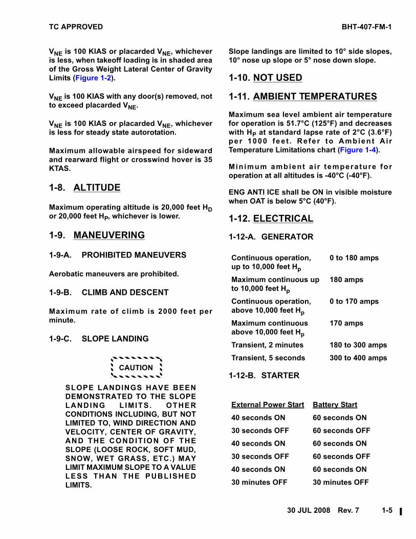
VNE is 100 KIAS or placarded VNE, whicheveris less, when takeoff loading is in shaded areaof the Gross Weight Lateral Center of GravityLimits (Figure 1-2).
VNE is 100 KIAS with any door(s) removed, notto exceed placarded VNE.
VNE is 100 KIAS or placarded VNE, whicheveris less for steady state autorotation.
Maximum allowable airspeed for sidewardand rearward flight or crosswind hover is 35KTAS.
1-8. ALTITUDE
Maximum operating altitude is 20,000 feet HDor 20,000 feet HP, whichever is lower.
1-9. MANEUVERING
1-9-A. PROHIBITED MANEUVERS
Aerobatic maneuvers are prohibited.
1-9-B. CLIMB AND DESCENT
Maximum rate of climb is 2000 feet perminute.
1-9-C. SLOPE LANDING
CAUTION
SLOPE LANDINGS HAVE BEENDEMONSTRATED TO THE SLOPELANDING L IMITS. OTHERCONDITIONS INCLUDING, BUT NOTLIMITED TO, WIND DIRECTION ANDVELOCITY, CENTER OF GRAVITY,AND THE CONDIT ION OF THESLOPE (LOOSE ROCK, SOFT MUD,SNOW, WET GRASS, ETC.) MAYLIMIT MAXIMUM SLOPE TO A VALUELESS THAN THE PUBLISHEDLIMITS.
Slope landings are limited to 10° side slopes,10° nose up slope or 5° nose down slope.
1-10. NOT USED
1-11. AMBIENT TEMPERATURES
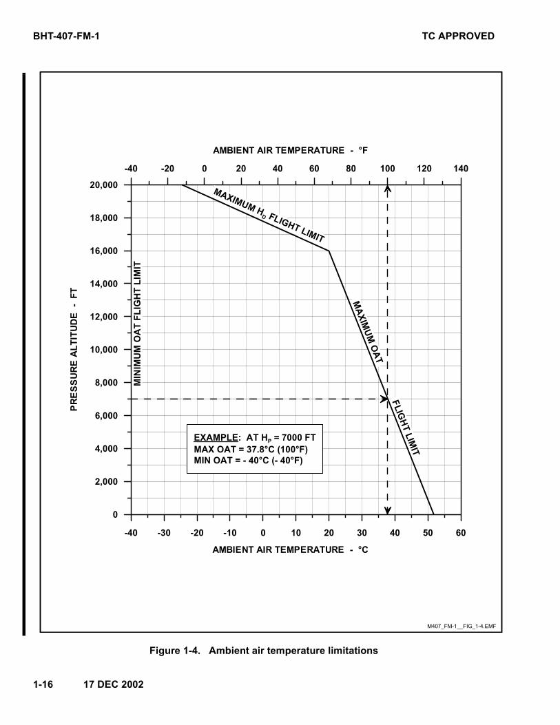
Maximum sea level ambient air temperaturefor operation is 51.7°C (125°F) and decreaseswith HP at standard lapse rate of 2°C (3.6°F)per 1000 fee t . Refer to Ambien t A i rTemperature Limitations chart (Figure 1-4).
Min imum ambient a i r temperature foroperation at all altitudes is -40°C (-40°F).
ENG ANTI ICE shall be ON in visible moisturewhen OAT is below 5°C (40°F).
1-12. ELECTRICAL
1-12-A. GENERATOR
1-12-B. STARTER
Continuous operation,up to 10,000 feet Hp
0 to 180 amps
Maximum continuous up to 10,000 feet Hp
180 amps
Continuous operation,above 10,000 feet Hp
0 to 170 amps
Maximum continuous above 10,000 feet Hp
170 amps
Transient, 2 minutes 180 to 300 amps
Transient, 5 seconds 300 to 400 amps
External Power Start Battery Start
40 seconds ON 60 seconds ON
30 seconds OFF 60 seconds OFF
40 seconds ON 60 seconds ON
30 seconds OFF 60 seconds OFF
40 seconds ON 60 seconds ON
30 minutes OFF 30 minutes OFF
BHT-407-FM-1 TC APPROVED
1-6———Rev. 7—30 JUL 2008
NOTE
28 VDC GPU for starting shall belimited to 500 amps.
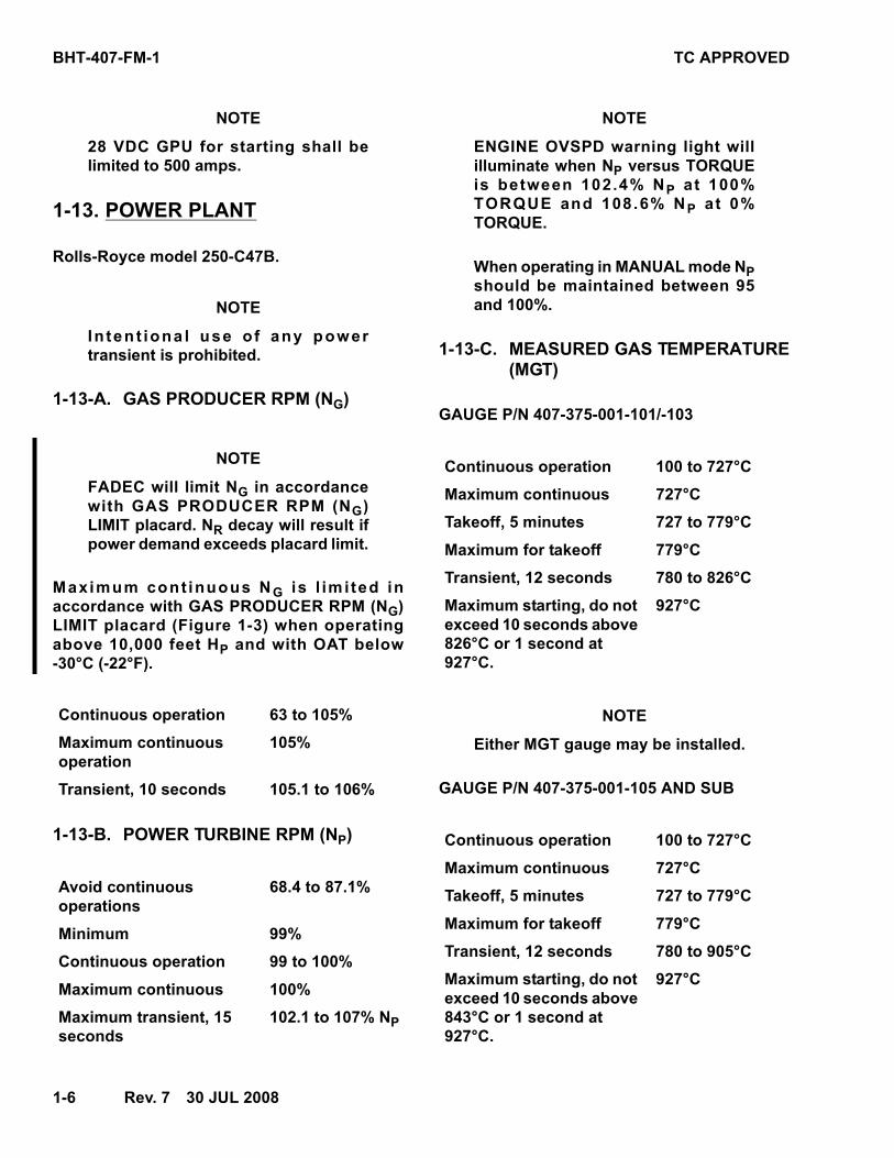
1-13. POWER PLANT
Rolls-Royce model 250-C47B.
NOTE
Inten t iona l use o f any powertransient is prohibited.
1-13-A. GAS PRODUCER RPM (NG)
NOTE
FADEC will limit NG in accordancewith GAS PRODUCER RPM (NG)LIMIT placard. NR decay will result ifpower demand exceeds placard limit.
Maximum cont inuous NG is l im i ted inaccordance with GAS PRODUCER RPM (NG)LIMIT placard (Figure 1-3) when operatingabove 10,000 feet HP and with OAT below-30°C (-22°F).
1-13-B. POWER TURBINE RPM (NP)
NOTE
ENGINE OVSPD warning light willilluminate when NP versus TORQUEis between 102.4% NP at 100%TORQUE and 108.6% NP at 0%TORQUE.
When operating in MANUAL mode NPshould be maintained between 95and 100%.
1-13-C. MEASURED GAS TEMPERATURE(MGT)
GAUGE P/N 407-375-001-101/-103
NOTE
Either MGT gauge may be installed.
GAUGE P/N 407-375-001-105 AND SUB
Continuous operation 63 to 105%
Maximum continuous operation
105%
Transient, 10 seconds 105.1 to 106%
Avoid continuousoperations
68.4 to 87.1%
Minimum 99%
Continuous operation 99 to 100%
Maximum continuous 100%
Maximum transient, 15 seconds
102.1 to 107% NP
Continuous operation 100 to 727°C
Maximum continuous 727°C
Takeoff, 5 minutes 727 to 779°C
Maximum for takeoff 779°C
Transient, 12 seconds 780 to 826°C
Maximum starting, do not exceed 10 seconds above 826°C or 1 second at 927°C.
927°C
Continuous operation 100 to 727°C
Maximum continuous 727°C
Takeoff, 5 minutes 727 to 779°C
Maximum for takeoff 779°C
Transient, 12 seconds 780 to 905°C
Maximum starting, do not exceed 10 seconds above 843°C or 1 second at 927°C.
927°C
TC APPROVED BHT-407-FM-1
30 JUL 2008—Rev. 7———1-7
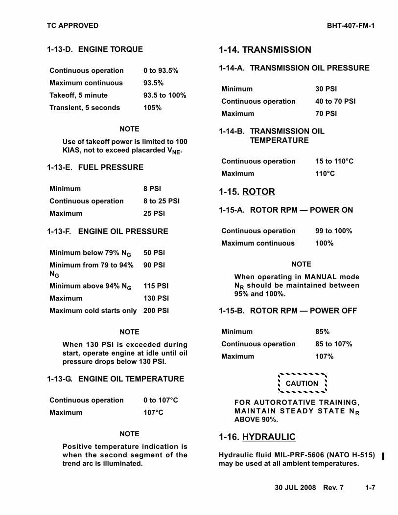
1-13-D. ENGINE TORQUE
NOTE
Use of takeoff power is limited to 100KIAS, not to exceed placarded VNE.
1-13-E. FUEL PRESSURE
1-13-F. ENGINE OIL PRESSURE
NOTE
When 130 PSI is exceeded duringstart, operate engine at idle until oilpressure drops below 130 PSI.
1-13-G. ENGINE OIL TEMPERATURE
NOTE
Positive temperature indication iswhen the second segment of thetrend arc is illuminated.
1-14. TRANSMISSION
1-14-A. TRANSMISSION OIL PRESSURE
1-14-B. TRANSMISSION OILTEMPERATURE
1-15. ROTOR
1-15-A. ROTOR RPM — POWER ON
NOTE
When operating in MANUAL modeNR should be maintained between95% and 100%.
1-15-B. ROTOR RPM — POWER OFF
CAUTION
FOR AUTOROTATIVE TRAINING,MAINTAIN STEADY STATE N RABOVE 90%.
1-16. HYDRAULIC
Hydraulic fluid MIL-PRF-5606 (NATO H-515)may be used at all ambient temperatures.
Continuous operation 0 to 93.5%
Maximum continuous 93.5%
Takeoff, 5 minute 93.5 to 100%
Transient, 5 seconds 105%
Minimum 8 PSI
Continuous operation 8 to 25 PSI
Maximum 25 PSI
Minimum below 79% NG 50 PSI
Minimum from 79 to 94% NG
90 PSI
Minimum above 94% NG 115 PSI
Maximum 130 PSI
Maximum cold starts only 200 PSI
Continuous operation 0 to 107°C
Maximum 107°C
Minimum 30 PSI
Continuous operation 40 to 70 PSI
Maximum 70 PSI
Continuous operation 15 to 110°C
Maximum 110°C
Continuous operation 99 to 100%
Maximum continuous 100%
Minimum 85%
Continuous operation 85 to 107%
Maximum 107%
BHT-407-FM-1 TC APPROVED
1-8———Rev. 7—30 JUL 2008
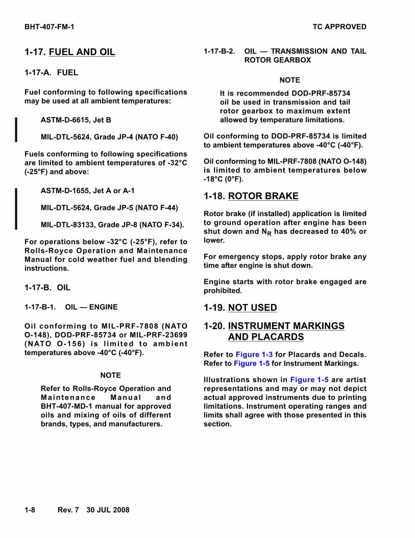
1-17. FUEL AND OIL
1-17-A. FUEL
Fuel conforming to following specificationsmay be used at all ambient temperatures:
ASTM-D-6615, Jet B
MIL-DTL-5624, Grade JP-4 (NATO F-40)
Fuels conforming to following specificationsare limited to ambient temperatures of -32°C(-25°F) and above:
ASTM-D-1655, Jet A or A-1
MIL-DTL-5624, Grade JP-5 (NATO F-44)
MIL-DTL-83133, Grade JP-8 (NATO F-34).
For operations below -32°C (-25°F), refer toRolls-Royce Operation and MaintenanceManual for cold weather fuel and blendinginstructions.
1-17-B. OIL
1-17-B-1. OIL — ENGINE
Oil conforming to MIL-PRF-7808 (NATOO-148), DOD-PRF-85734 or MIL-PRF-23699(NATO O-156) is l im i ted to ambienttemperatures above -40°C (-40°F).
NOTE
Refer to Rolls-Royce Operation andMaintenance Manual andBHT-407-MD-1 manual for approvedoils and mixing of oils of differentbrands, types, and manufacturers.
1-17-B-2. OIL — TRANSMISSION AND TAILROTOR GEARBOX
NOTE
It is recommended DOD-PRF-85734oil be used in transmission and tailrotor gearbox to maximum extentallowed by temperature limitations.
Oil conforming to DOD-PRF-85734 is limitedto ambient temperatures above -40°C (-40°F).
Oil conforming to MIL-PRF-7808 (NATO O-148)is limited to ambient temperatures below-18°C (0°F).
1-18. ROTOR BRAKE
Rotor brake (if installed) application is limitedto ground operation after engine has beenshut down and NR has decreased to 40% orlower.
For emergency stops, apply rotor brake anytime after engine is shut down.
Engine starts with rotor brake engaged areprohibited.
1-19. NOT USED
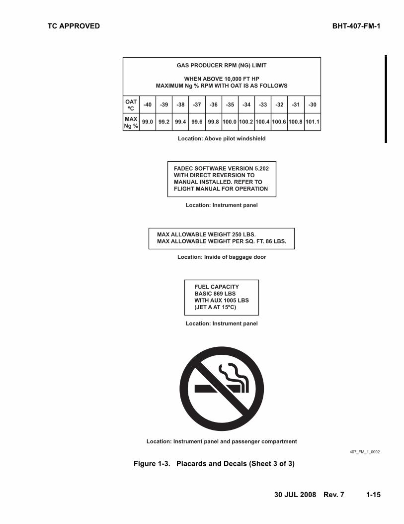
1-20. INSTRUMENT MARKINGSAND PLACARDS
Refer to Figure 1-3 for Placards and Decals.Refer to Figure 1-5 for Instrument Markings.
Illustrations shown in Figure 1-5 are artistrepresentations and may or may not depictactual approved instruments due to printinglimitations. Instrument operating ranges andlimits shall agree with those presented in thissection.
TC APPROVED BHT-407-FM-1
30 JUL 2008 Rev. 7 1-15
Figure 1-3. Placards and Decals (Sheet 3 of 3)
FADEC SOFTWARE VERSION 5.202
WITH DIRECT REVERSION TO
MANUAL INSTALLED. REFER TO
FLIGHT MANUAL FOR OPERATION
Location: Instrument panel
MAX ALLOWABLE WEIGHT 250 LBS.
MAX ALLOWABLE WEIGHT PER SQ. FT. 86 LBS.
Location: Inside of baggage door
FUEL CAPACITY
BASIC 869 LBS
WITH AUX 1005 LBS
(JET A AT 15ºC)
Location: Instrument panel
GAS PRODUCER RPM (NG) LIMIT
WHEN ABOVE 10,000 FT HP
MAXIMUM Ng % RPM WITH OAT IS AS FOLLOWS
Location: Above pilot windshield
OAT
ºC
MAX
Ng %99.0
-40
99.2
-39
99.4
-38
99.6
-37
99.8
-36
100.0
-35
100.2
-34
100.4
-33
100.6
-32
100.8
-31
101.1
-30
Location: Instrument panel and passenger compartment
407_FM_1_0002
BHT-407-FM-1 TC APPROVED
1-16 17 DEC 2002
Figure 1-4. Ambient air temperature limitations
-40 -30 -20 -10 0 10 20 30 40 50 60
AMBIENT AIR TEMPERATURE - °C
0
2,000
4,000
6,000
8,000
10,000
12,000
14,000
16,000
18,000
20,000
PR
ES
SU
RE
ALT
ITU
DE
- F
T
-40 -20 0 20 40 60 80 100 120 140
AMBIENT AIR TEMPERATURE - °F M
INIM
UM
OA
T FL
IGH
T LI
MIT
MAXIM
UM O
AT
EXAMPLE: AT HP = 7000 FTMAX OAT = 37.8°C (100°F)MIN OAT = - 40°C (- 40°F)
FLIGHT LIM
IT
MAXIMUM HD FLIGHT LIMIT
M407_FM-1__FIG_1-4.EMF
TC APPROVED BHT-407-FM-1
17 DEC 2002 1-17
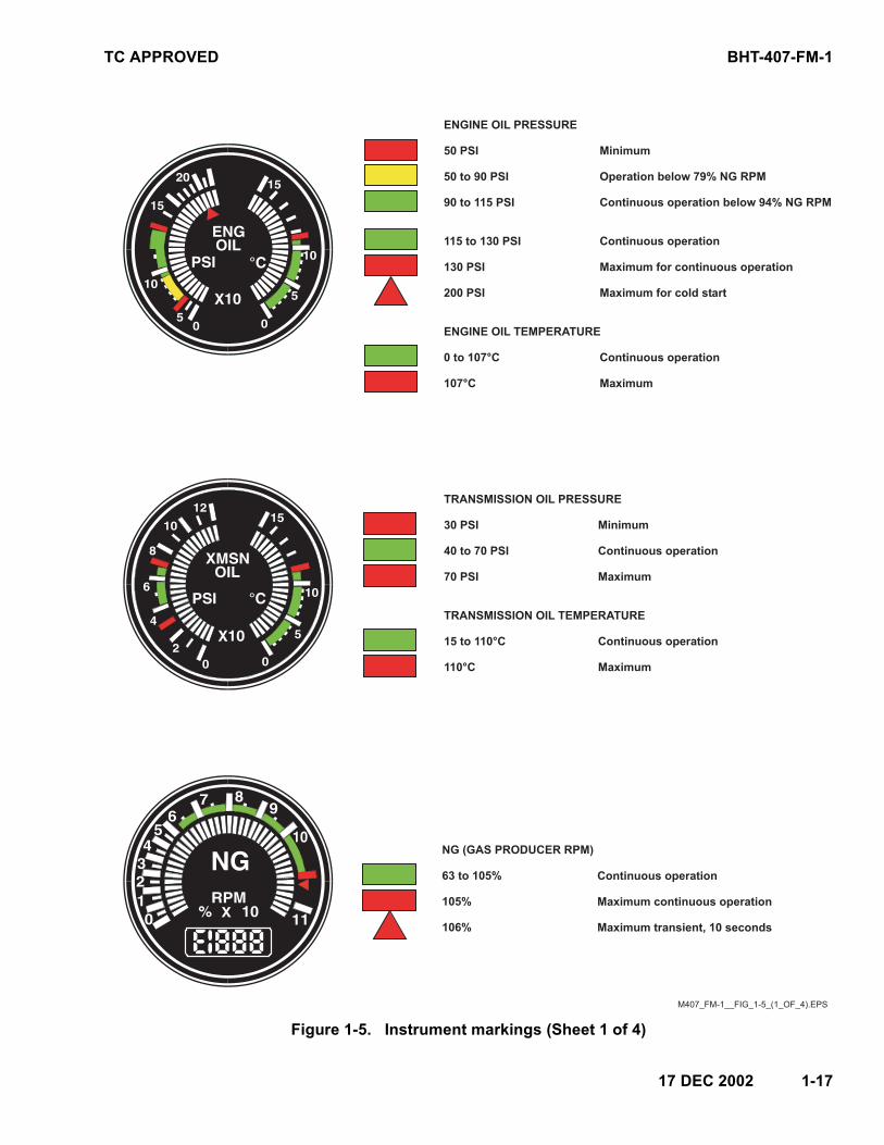
Figure 1-5. Instrument markings (Sheet 1 of 4)
ENGINE OIL PRESSURE
50 PSI
50 to 90 PSI
90 to 115 PSI
115 to 130 PSI
130 PSI
200 PSI
ENGINE OIL TEMPERATURE
0 to 107°C
107°C
Minimum
Operation below 79% NG RPM
Continuous operation below 94% NG RPM
Maximum for continuous operation
Maximum for cold start
Continuous operation
Maximum
Continuous operation
TRANSMISSION OIL PRESSURE
30 PSI
40 to 70 PSI
70 PSI
TRANSMISSION OIL TEMPERATURE
15 to 110°C
110°C
Minimum
Continuous operation
Maximum
Continuous operation
Maximum
NG (GAS PRODUCER RPM)
63 to 105%
105%
106%
Continuous operation
Maximum continuous operation
Maximum transient, 10 seconds
M407_FM-1__FIG_1-5_(1_OF_4).EPS
BHT-407-FM-1 TC APPROVED
1-18 Rev. 7 30 JUL 2008
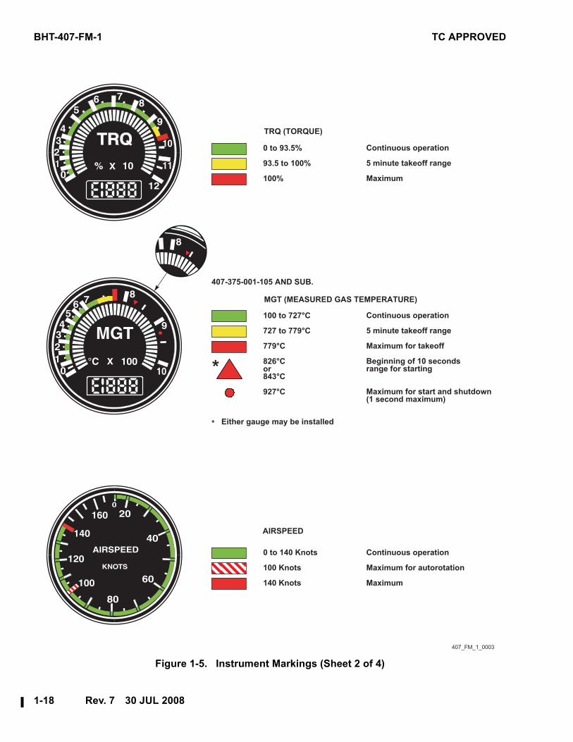
Figure 1-5. Instrument Markings (Sheet 2 of 4)
TRQ (TORQUE)
MGT (MEASURED GAS TEMPERATURE)
Continuous operation
5 minute takeoff range
Maximum for takeoff
Beginning of 10 seconds
range for starting
Maximum for start and shutdown
(1 second maximum)
407_FM_1_0003
Continuous operation
Maximum for autorotation
Maximum
407-375-001-105 AND SUB.
Either gauge may be installed*
*
AIRSPEED
0 to 93.5%
93.5 to 100%
100%
0 to 140 Knots
100 Knots
140 Knots
100 to 727°C
727 to 779°C
779°C
826°C
or
843°C
927°C
Continuous operation
5 minute takeoff range
Maximum
TC APPROVED BHT-407-FM-1
30 JUL 2008 Rev. 7 1-19
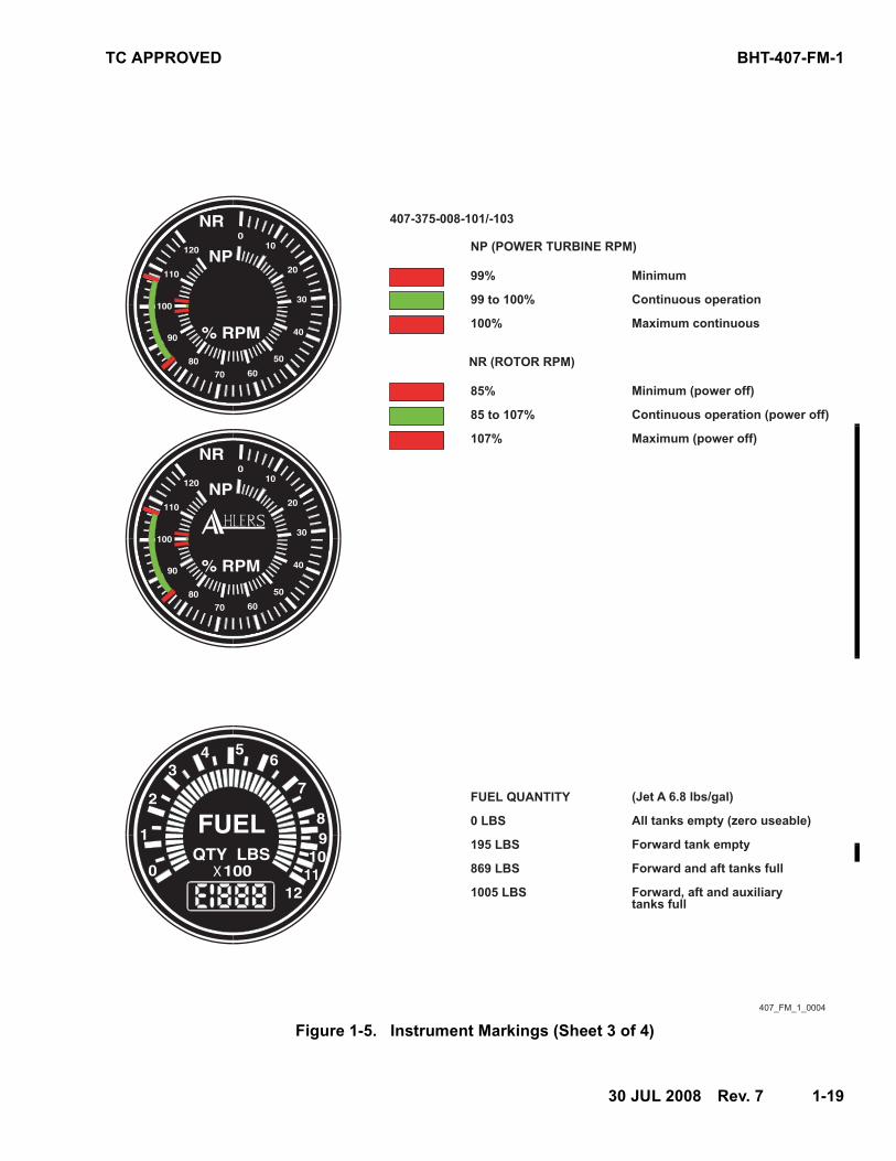
Figure 1-5. Instrument Markings (Sheet 3 of 4)
99%
99 to 100%
100%
Minimum
Continuous operation
Maximum continuous
NP (POWER TURBINE RPM)
407_FM_1_0004
FUEL QUANTITY
0 LBS
195 LBS
869 LBS
1005 LBS
(Jet A 6.8 lbs/gal)
All tanks empty (zero useable)
Forward tank empty
Forward and aft tanks full
Forward, aft and auxiliary
tanks full
85%
85 to 107%
107%
Minimum (power off)
Continuous operation (power off)
Maximum (power off)
NR (ROTOR RPM)
407-375-008-101/-103
BHT-407-FM-1 TC APPROVED
1-20 Rev. 3 26 APR 2005
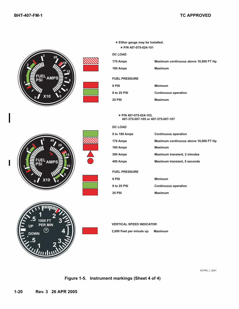
Figure 1-5. Instrument markings (Sheet 4 of 4)
407FM_1_0001
DC LOAD
DC LOAD
FUEL PRESSURE
FUEL PRESSURE
* Either gauge may be installed.
* P/N 407-075-024-101
* P/N 407-075-024-103, 407-375-007-105 or 407-375-007-107
170 Amps
0 to 180 Amps
180 Amps
180 Amps
170 Amps
300 Amps
400 Amps
8 PSI
8 PSI
8 to 25 PSI
8 to 25 PSI
25 PSI
25 PSI
Maximum continuous above 10,000 FT Hp
Continuous operation
Maximum
Maximum
Maximum continuous above 10,000 FT Hp
Maximum transient, 2 minutes
Maximum transient, 5 seconds
Continuous operation
Continuous operation
Maximum
Maximum
Minimum
Minimum
VERTICAL SPEED INDICATOR
2,000 Feet per minute up Maximum
TC APPROVED BHT-407-FM-1
19 FEB 2007—Rev. 5———2-7
7. Control linkages to swashplate —Condition, security of attachmentbolts and locking hardware.
8. Control tube hydraulics-off balancesprings — Condition and security.
9. Hydraulic reservoir filler cap —Closed and locked.
10. Hydraulic system filters — Bypassindicator retracted.
11. Hydraulic actuators and lines —Condition, security, interference,leakage.
2-3-B-7. FUSELAGE — CABIN LEFT SIDE
1. Forward fairing and access door —Secured.
2. Cabin doors and hinge bolts —Condition and security.
3. Windows — Condition and security.
4. Hydraulic reservoir — Check fluidlevel.
5. Landing gear — Condition andground handling wheel removed.
6. Forward and aft crosstube fairings (ifinstalled) — Secured, condition, andaligned.
7. Left static port — Condition.
2-3-B-8. FUSELAGE — FRONT
1. Exterior surfaces — Condition.
2. Windshield — Condition andcleanliness.
3. Battery and vent lines — Conditionand security.
4. HOUR METER circuit breaker — In.
5. Battery access door — Secured.
6. Pitot tube — Cover removed, clear ofobstructions.
7. External power door — Conditionand security.
8. Landing light lamps — Condition.
9. Antennas — Condition and security.
2-4. INTERIOR AND PRESTARTCHECK
1. Cabin interior — Clean, equipmentsecured.
2. Fire extinguisher — Installed andsecured.
3. Cabin loading — Maintain CG withinlimits.
4. Passenger seat belts — Secured.
5. Copilot seat belt — Secured (if solo).
6. Doors — Secured.
7. Throttle — Closed.
8. LDG LTS switch — OFF.
9. Communications switches — Set.
10. Altimeter — Set.
11. Instruments — Correct indications.
12. Overhead switches — Set:
a. BATT switch — OFF.
b. GEN switch — OFF.
c. PART SEP switch (if installed) —OFF.
d. ANTI COLL LT switch — ANTICOLL LT (on).
e. HYD SYS switch — HYD SYS(on).
f. CABIN LT/PASS switch — OFF.
g. POS LT switch — As desired.
h. DEFOG switch — OFF.
i. PITOT HEATER switch — OFF.
BHT-407-FM-1 TC APPROVED
2-8———Rev. 7—30 JUL 2008
j. ENG ANTI ICE switch — OFF.
k. AVIONICS MASTER switch —OFF.
l. HEATER switch (if installed) —OFF.
m. INSTR LT rheostat — OFF.
13. Overhead circuit breaker switches —OFF.
14. Overhead circuit breakers — In.
15. Rotor brake handle (if installed) — Upand latched.
CAUTION
28 VDC GPU SHALL BE 500AMPERES OR LESS TO REDUCERISK OF STARTER DAMAGE FROMOVERHEATING.
16. GPU — Connected (if used).
17. BATT switch — ON for battery start,ON for GPU start, OFF for battery cartstart. Observe the following:
a. Low rotor audio horn activated.
NOTE
With “Ah lers” NR/NP gaugeinstalled, NR/NP needles do not selftest.
b. For 8 seconds,
(1) Trend arcs on LCDinstruments indicate fullscale.
(2) TORQUE and NG digitsdisplay 8188.8.
(3) MGT and FUEL digitsdisplay 81888.
(4) NR and NP needles move to107% and 100%,respectively.
c. After 3 seconds; ENG OUT,FADEC DEGRADE, FADECFAULT, RESTART FAULT, andENGINE OVSPD lightsilluminate with activation ofengine out audio for 3 seconds.
d. ENG OUT light re-illuminateswith reactivation of engine outaudio, after 3 seconds.
18. HORN MUTE button — Press to mute.
19. Caution lights — ENG OUT, XMSNOIL PRESS, RPM, HYDRAULICSYSTEM, GEN FAIL, L/FUEL BOOST,R/FUEL BOOST, L/FUEL XFR, and R/FUEL XFR will be illuminated.
NOTE
L/FUEL XFR and R/FUEL XFR will notbe illuminated when forward fueltank is empty.
20. PEDAL STOP PTT switchannunciator:
Pedals — Centered.
Press — Verify PEDAL STOP cautionand ENGAGED annunciatorilluminated and left pedal travelrestricted.
Release — Verify PEDAL STOPcaution and ENGAGED annunciatorextinguished and both pedals travelunrestricted.
21. Flight controls — Loosen frictions;check travel and verify CYCLICCENTERING light operation; positionfor start. Tighten friction as desired.
22. Throttle — Check freedom of traveland appropriate operation at OFF, I(idle), FLY and MAX positions.Return throttle to OFF position.
NOTE
With INSTR LT rheostat on and CAUTLT switch positioned to DIM, caution
TC APPROVED BHT-407-FM-1
30 JUL 2008—Rev. 7———2-9
lights are dimmed to a fixed intensityand cannot be adjusted by INSTR LTrheostat.
23. INSTR LT rheostat — As desired.
24. CAUT LT switch — As desired.
25. FUEL BOOST/XFR circuit breakerswitches — LEFT (on) and RIGHT(on) and verify all boost and transfercaution lights extinguish.
26. FUEL pressure — Check.
27. CAUTION LT TEST button — Press totest.
28. INSTR CHK button — Press andcheck for exceedances.
29. LCD TEST button — Press to test, ifdesired.
30. FADEC HORN TEST button — Pressto test.
31. FADEC MODE switch — AUTO.
32. FUEL VALVE switch — ON, guardclosed, FUEL VALVE lightilluminates then extinguishes.
33. FUEL QTY — Check TOTAL and FWDtank quantity.
34. OAT/VOLTS display — Check OATand select VOLTS.
CAUTION
ANY ATTEMPT TO START ENGINEWHEN VOLTAGE IS BELOW 24VOLTS MAY RESULT IN A HOTSTART. MONITOR FOR FADECFAILURE. IF FADEC FAILS (FADECFAIL WARNING LIGHT), ABORTSTART BY ROLLING THROTTLE TOCUTOFF AND ENGAGE STARTERTO REDUCE MGT.
2-5. ENGINE START
1. Collective — Full down.
2. Cyclic and pedals — Centered andCYCLIC CENTERING lightextinguished.
NOTE
If throttle is positioned in idle formore than 60 seconds, starterlatching is disabled and throttle mustbe repositioned to cut off and thenback to idle to enable it for another 60seconds.
It is recommended that MGT bebelow 150°C when below 10,000 feetHP or below 65 °C when above 10,000feet HP prior to attempting an enginesta r t . Compl iance w i th th isrecommendation will allow for coolerstarts and reduce potentia l ofreaching hot start abort limits. Referto DRY MOTORING RUN, paragraph2-5-A.
3. Throttle — Idle position.
4. START switch — Momentarily press(hold for approximately 1 second)and observe START and AUTORELIGHT lights are illuminated.
5. MGT — Monitor.
CAUTION
IF MAIN ROTOR IS NOT ROTATINGBY 25% NG, ABORT START BYROLLING THROTTLE TO CUTOFF.ENSURE STARTER HASDISENGAGED WHEN MGTDECREASES BELOW 150°C.
6. START light — Extinguished at 50%NG (starter has disengaged).
7. AUTO RELIGHT light — Extinguishedat 60% NG.
8. ENG and XMSN OIL pressures —Check.
BHT-407-FM-1 TC APPROVED
2-10———Rev. 5—19 FEB 2007
CAUTION
IF ENGINE HAS BEEN SHUT DOWNFOR MORE THAN 15 MINUTES,STABILIZE AT IDLE FOR 1 MINUTEBEFORE INCREASING THROTTLE.
NOTE
During cold temperature operations,normal transmission and engine oilpressure limits may be exceededduring start. Stabilize engine at idleuntil minimum temperature andpressure limits are attained.
9. Idle — 63 ±1% NG.
10. BATT switch — ON (if applicable).
11. GPU — Disconnect and close door (ifapplicable).
12. GEN switch — GEN (on); observeGEN FAIL light extinguishes.
NOTE
Turn generator OFF if ammeterindication drops to zero amps afteran initial full scale indication. Onereset is allowed. RESET generatorand then turn generator back ON(applicable with AMPS/FUEL PSIgauge PN 407-075-024-101 and sub.).Refer to BHT-407-MD-1.
13. Voltmeter — 28.5 ±0.5 volts.
14. FLIGHT INSTR circuit breakerswitches (3) (if installed) — DG, ATTand TURN (on).
NOTE
If dual controls are installed, guardthrottle to prevent inadvertentmanipulation from co-pilot position.
2-5-A. DRY MOTORING RUN
The following procedure is used to reduceresidual MGT to recommended levels forengine start.
1. Throttle — Closed position.
2. START switch — Hold engaged for 15seconds, then release.
Follow ENGINE START procedure, paragraph2-5, once 0% NG is indicated.
2-5-B. ALTERNATE ENGINE START
This procedure may be used in hot and/orhigh altitude environment where aborted hotstarts have been experienced and when priortroubleshooting has not revealed any enginemaintenance issues.
1. Collective — Full down.
2. Cyclic and pedals — Centered andCYCLIC CENTERING lightextinguished.
NOTE
It is recommended that MGT bebelow 150°C when below 10,000 feetHP or below 65°C when above 10,000feet HP prior to attempting an enginesta r t . Compl iance w i th th isrecommendation will allow for coolerstarts and reduce potentia l ofreaching hot start abort limits. Referto DRY MOTORING RUN, paragraph2-5-A.
3. Throttle — Closed position.
4. START switch — Hold engaged andobserve START and AUTO RELIGHTlights are illuminated.
a. Throttle — Open to IDLE atapproximately 16% NG.
5. MGT — Monitor.
TC APPROVED BHT-407-FM-1
20 JUN 2007—Rev. 6———2-15
2-11. ENGINE SHUTDOWN
1. Collective — Full down.
2. Cyclic and pedals — Centered andCYCLIC CENTERING lightextinguished.
3. Cyclic friction — Increase so thatcyclic maintains centered position.
4. LDG LTS switch — OFF.
5. Throttle — Reduce to idle stop.Check RPM warning light illuminatedand audio on at 95% NR.
NOTE
If dual controls are installed, guardthrottle to prevent inadvertentmanipulation from co-pilot position.
6. HORN MUTE button — Press to mute.
7. MGT — Stabilize at idle for 2 minutes.
8. ENG ANTI ICE switch — OFF.
9. FLIGHT INSTR circuit breakersswitches (if installed) — OFF.
10. FUEL BOOST/XFR LEFT circuitbreaker switch — OFF.
NOTE
Left fuel boost and transfer pumpswill continue to operate until eitherLEFT FUEL BOOST/XFR circuitbreaker switch (highlighted withyellow border) or FUEL VALVEswitch is positioned to OFF. Thesepumps operate directly from batteryand will not be deactivated whenBATT switch is OFF. Battery powerwill be depleted if both switchesremain on.
11. ELT (if installed) — Check forinadvertent transmission.
12. AVIONICS MASTER switch — OFF.
13. GEN switch — OFF.
14. OVSPD TEST button — If required;press, hold 1 second, and release.
NOTE
Overspeed shutdown test should beaccompl ished on f i rs t eng ineshutdown of the day . ENGINEOVSPD l ight wi l l momentar i lyilluminate in addition to those lightsthat il luminate during a normalshutdown.
15. IDLE REL switch — Press and hold.
CAUTION
POSITIONING THROTTLE OUT OFCUT-OFF DURING NG SPOOL DOWNMAY CAUSE POST ENGINESHUTDOWN FIRE.
16. Throttle — Closed; check MGT andNG decreasing, ENGINE OUTwarning light illuminated and audioon at 55 ±1%.
17. HORN MUTE button — Press to mute.
CAUTION
AVOID RAPID ENGAGEMENT OFROTOR BRAKE IF HELICOPTER ISON ICE OR OTHER SLIPPERY ORLOOSE SURFACE TO PREVENTROTATION OF HELICOPTER.
18. Rotor brake (if installed) — Apply fullrotor brake at or below 40% NR.Return rotor brake handle to stowedposition just prior to main rotorstopping.
19. FUEL VALVE switch — OFF.
BHT-407-FM-1 TC APPROVED
2-16———Rev. 7—30 JUL 2008
CAUTION
DO NOT INCREASE COLLECTIVE ORAPPLY LEFT TAIL ROTOR PEDALTO SLOW ROTOR DURINGCOASTDOWN.
20. Pilot — Remain on flight controlsuntil rotor has come to a completestop.
21. All overhead switches, except HYDSYS switch — OFF.
NOTE
Ensure engine ro ta t ion hascomplete ly s topped pr io r topositioning BATT switch to OFF.
22. BATT switch — OFF, with NG at 0%.
CAUTION
APPLICABLE MAINTENANCEACTION MUST BE PERFORMEDPRIOR TO FURTHER FLIGHT IF AFADEC LIGHT HAS ILLUMINATEDDURING THE PREVIOUS FLIGHT ORON ENGINE SHUTDOWN.
NOTE
If shutting down at, or refueling to,between approximately 195 to 213
pounds total fuel quantity, up to 18pounds of fuel may remain in forwardfuel cell as unusable.
2-12. POSTFLIGHT CHECK
If any of following conditions exist:
• Thunderstorms are in local area orforecasted.
• Winds in excess of 35 knots or agust spread of 15 knots exists or isforecasted.
• Helicopter is parked within 150 feetof hovering or taxiing aircraft thatare in excess of basic GW ofhelicopter.
• Helicopter to be left unattended.
Perform following:
1. Install main rotor blade tie-downs.
2. Secure tail rotor loosely to tailboomwith tie-down strap to preventexcessive flapping.
3. Install exhaust cover, engine inletprotective plugs and pitot cover.
NOTE
Refer to BHT-407-MD-1 for additionaltie-down data.
TC APPROVED BHT-407-FM-1
30 JUL 2008 Rev. 7 3-1/3-2
Section 3EMERGENCY/MALFUNCTION PROCEDURES
3TABLE OF CONTENTS
Paragraph PageSubject Number Number
Introduction ............................................................................................ 3-1 ........... 3-3Definitions .............................................................................................. 3-2 ........... 3-3Engine ..................................................................................................... 3-3 ........... 3-3
Engine Failure .................................................................................... 3-3-A ....... 3-3Engine Restart in Flight..................................................................... 3-3-B ....... 3-4Engine Underspeed ........................................................................... 3-3-C ....... 3-6Engine Overspeed ............................................................................. 3-3-D ....... 3-6Engine Compressor Stall .................................................................. 3-3-E ....... 3-6Engine Hot Start/Shutdown .............................................................. 3-3-F........ 3-7Engine Oil Pressure Low or Fluctuating.......................................... 3-3-G....... 3-7Engine Oil Temperature High ........................................................... 3-3-H ....... 3-7Driveshaft Failure............................................................................... 3-3-J........ 3-8FADEC Failure.................................................................................... 3-3-K ....... 3-8
Fire .......................................................................................................... 3-4 ........... 3-9Engine Fire on Ground ...................................................................... 3-4-A ....... 3-9Engine Fire During Flight .................................................................. 3-4-B ....... 3-9Cabin Smoke or Fumes ..................................................................... 3-4-C ....... 3-9
Tail Rotor ................................................................................................ 3-5 ........... 3-10Complete Loss of Tail Rotor Thrust................................................. 3-5-A ....... 3-10Fixed Pitch Failures ........................................................................... 3-5-B ....... 3-10
Hydraulic System................................................................................... 3-6 ........... 3-11Loss of Hydraulic Pressure .............................................................. 3-6-A ....... 3-11Flight Control Actuator Malfunction ................................................ 3-6-B ....... 3-12
Electrical System ................................................................................... 3-7 ........... 3-12Generator Failure ............................................................................... 3-7-A ....... 3-12Excessive Electrical Load ................................................................. 3-7-B ....... 3-12
Fuel System............................................................................................ 3-8 ........... 3-13Cyclic Jam .............................................................................................. 3-9 ........... 3-13Warning, Caution, and Advisory Lights/Messages ............................ 3-10 ......... 3-14
LIST OF TABLES
Table PageSubject Number Number
Warning (Red) Lights............................................................................. 3-1 ........... 3-15Caution (Amber) and Advisory (White/Green) Lights......................... 3-2 ........... 3-16

TC APPROVED BHT-407-FM-1
30 JUL 2008 Rev. 7 3-3
Section 3EMERGENCY/MALFUNCTION PROCEDURES
33-1. INTRODUCTIONFollowing procedures contain indications offailures or malfunctions which affect safety ofcrew, hel icopter, ground personnel orproperty; use of emergency features ofprimary and backup systems; and appropriatewarnings, cautions, and explanatory notes.Tables 3-1 and 3-2 list fault conditions andcorrective actions for warning lights andcaution/advisory lights respectively.
NOTE
All corrective action procedureslisted herein assume pilot gives firstpriority to helicopter control and asafe flight path.
A tripped circuit breaker should notbe reset in flight unless deemednecessary for safe completion of theflight.
If a tripped circuit breaker is deemednecessary for safe completion of theflight, it should only be reset onetime.
Helicopter should not be operated followingany precautionary landing until cause ofmalfunct ion has been determined andcorrective maintenance action taken.
3-2. DEFINITIONSFollowing terms indicate degree of urgency inlanding helicopter.
Fo l lowing terms are used to descr ibeoperating condition of a system, subsystem,assembly, or component.
3-3. ENGINE3-3-A. ENGINE FAILURE
3-3-A-1. ENGINE FAILURE — HOVERING
INDICATIONS:
1. Left yaw.
2. ENGINE OUT and RPM warninglights illuminated.
LAND AS SOON AS POSSIBLE
Land without delay at nearest suitable area (i.e., open field) at which a safe approach and landing is reasonably assured.
LAND AS SOON AS PRACTICAL
Landing site and duration of flight are at discretion of pilot. Extended flight beyond nearest approved landing area is not recommended.
Affected Fails to operate in intended or usual manner.
Normal Operates in intended or usual manner.
BHT-407-FM-1 TC APPROVED
3-4 17 DEC 2002
3. Engine instruments indicate powerloss.
4. Engine out audio activated when NGdrops below 55%.
5. NR decreasing with RPM warninglight and audio on when NR dropsbelow 95%.
PROCEDURE:
1. Maintain heading and attitudecontrol.
2. Collective — Adjust to control NRand rate of descent. Increase prior toground contact to cushion landing.
NOTE
Amplitude of collective movement isa function of height above ground.Any forward airspeed will aid inability to cushion landing.
3. Land.
4. Shut down helicopter.
3-3-A-2. ENGINE FAILURE — INFLIGHT
INDICATIONS:
1. Left yaw.
2. ENGINE OUT and RPM warninglights illuminated.
3. Engine instruments indicate powerloss.
4. Engine out audio activated when NGdrops below 55%.
5. NR decreasing with RPM warninglight and audio on when NR dropsbelow 95%.
PROCEDURE:
1. Maintain heading and attitudecontrol.
2. Collective — Adjust as required tomaintain 85 to 107% NR.
NOTE
Mainta in ing NR a t h igh end ofoperat ing range w i l l p rov idemaximum rotor energy toaccomplish landing, but will causean increased rate of descent.
3. Cyclic — Adjust to obtain desiredautorotative AIRSPEED.
NOTE
Maximum AIRSPEED for steady stateautorotation is 100 KIAS. Minimumrate of descent airspeed is 55 KIAS.Maximum glide distance airspeed is80 KIAS.
4. Attempt engine restart if amplealtitude remains. (Refer to ENGINERESTART, paragraph 3-3-B).
5. FUEL VALVE switch — OFF.
6. At low altitude:
a. Throttle — Closed.
b. Flare to lose airspeed.
7. Apply collective as flare effectdecreases to further reduce forwardspeed and cushion landing. Uponground contact, collective shall bereduced smoothly while maintainingcyc l ic in neut ra l or cente redposition.
8. Complete helicopter shutdown.
3-3-B. ENGINE RESTART IN FLIGHT
An engine restart may be attempted in flight iftime and altitude permit.
TC APPROVED BHT-407-FM-1
30 JUL 2008 Rev. 7 3-9
PROCEDURE:
WARNING
WITHIN 2 TO 7 SECONDS AFTERTHE FADEC FAIL WARNING NR/NPMAY INCREASE RAPIDLY,REQUIRING POSITIVE MOVEMENTSOF COLLECTIVE AND THROTTLETO CONTROL NR.
1. Throttle — If time permits, matchthro t t le beze l pos i t ion to NGindication.
2. NR/NP — Maintain 95 to 100% withcollective and throttle.
3. FADEC MODE switch — Depress onetime, muting FADEC fail audio.
NOTE
Depressing FADEC MODE switchone time, will only mute FADEC failaudio. This step should not beaccomplished until pilot is firmlyestablished in MAN control.
4. Land as soon as practical.
5. Normal shutdown if possible.
3-4. FIRE3-4-A. ENGINE FIRE ON GROUND
INDICATIONS:
1. Smoke
2. Fumes
3. Fire
PROCEDURE:
1. Throttle — Closed.
2. FUEL VALVE switch — OFF.
3. GEN switch — OFF.
4. BATT switch — OFF.
5. Rotor brake (if installed) — Engage.
6. Exit helicopter.
3-4-B. ENGINE FIRE DURING FLIGHT
INDICATIONS:
1. Smoke
2. Fumes
3. Fire
PROCEDURE:
1. Inflight — Immediately enterautorotation.
2. Throttle — Closed.
3. FUEL VALVE switch — OFF.
4. If time permits, FUEL BOOST/XFRcircuit breaker switches — OFF.
5. Execute autorotative descent andlanding.
6. BATT switch — OFF.
NOTE
Do not restart engine until correctivemaintenance has been performed.
3-4-C. CABIN SMOKE OR FUMES
INDICATIONS:
1. Smoke
2. Fumes
BHT-407-FM-1 TC APPROVED
3-10 17 DEC 2002
PROCEDURE:
1. Inflight — Start descent
2. AIR COND BLO switch (if installed)— OFF
3. HEATER switch (if installed) — OFF
4. All vents — Open
5. Side windows — Open
If time and altitude permits:
6. Source — Attempt to identify andsecure.
7. If source is identified and smokeand/or fumes still persist — Land assoon as possible.
8. If source is identified and smokeand/or fumes are cleared — Land assoon as practical.
3-5. TAIL ROTORThere is no single emergency procedure forall types of antitorque malfunctions. One keyto a pilot successfully handling a tail rotoremergency lies in the abil ity to quicklyrecognize the type of malfunction that hasoccurred.
3-5-A. COMPLETE LOSS OF TAIL ROTOR THRUST
This is a situation involving a break in drivesystem (e.g., severed driveshaft), wherein tailrotor stops turning and delivers no thrust.
INDICATIONS:
1. Uncontrollable yawing to right (leftside slip).
2. Nose down tucking.
3. Possible roll of fuselage.
NOTE
Sever i ty o f in i t ia l react ion ofhe l icopter wi l l be a f fected byAIRSPEED, CG, power being used,and HD.
PROCEDURE:
3-5-A-1. HOVERING
Close thrott le and perform a hoveringautorotation landing. A slight rotation can beexpected on touchdown.
3-5-A-2. IN-FLIGHT
Reduce throttle to idle, immediately enterautorotat ion, and maintain a minimumAIRSPEED of 55 KIAS during descent.
NOTE
When a suitable landing site is notavailable, vertical fin may permitcontrolled flight at low power levelsand sufficient AIRSPEED. Duringfinal stages of approach, a mild flareshould be executed, making sure allpower to rotor is off . Maintainhelicopter in a slight f lare andsmoothly use collective to execute asoft, slightly nose-high landing.Landing on aft portion of skids willtend to correct side drif t . Thistechnique will, in most cases, resultin a run-on type landing.
CAUTION
IN A RUN-ON TYPE LANDINGAFTER TOUCHING DOWN, DO NOTUSE C Y C L I C T O R E D U C EFORWARD SPEED.
3-5-B. FIXED PITCH FAILURES
This is a situation involving inability tochange tail rotor thrust (blade angle) with anti-torque pedals.