Embed Size (px)
Citation preview

SASO IEC 60601-1-10
Medical electrical equipment –
Part 1-10: General requirements for basic safety and essential performance –
Collateral Standard: Requirements for the development of physiologic closed-loop controllers

SAUDI ARABIAN STANDARD SASO IEC60601-1-10/2008
2
CONTENTS
FOREWORD .................................................................................. .اإلشارة المرجعية غير معّرفة! خطأ INTRODUCTION ............................................................................ .اإلشارة المرجعية غير معّرفة! خطأ 1 Scope, object and related standards ............................................................................... 5
1.1 * Scope ................................................................................................................. 5 1.2 Object ................................................................................................................... 5 1.3 Related standards ................................................................................................. 5
1.3.1 IEC 60601-1 .............................................................................................. 5 1.3.2 Particular standards ................................................................................... 6
2 Normative references ..................................................................................................... 6 3 Terms and definitions ..................................................................................................... 6 4 * General requirements ................................................................................................ 11 5 ME EQUIPMENT identification, marking and documents .................................................... 12
5.1 * Instructions for use ........................................................................................... 12 5.2 Technical description ........................................................................................... 12
6 Accuracy of controls and instruments and protection against hazardous outputs ........... 12 6.1 * USABILITY .......................................................................................................... 12 6.2 ALARM SYSTEMS .................................................................................................... 12 6.3 * PCLCS VARIABLE logging ..................................................................................... 13 6.4 * DISTRIBUTED PCLCS ............................................................................................ 13
7 * PROGRAMMABLE ELECTRICAL MEDICAL SYSTEMS (PEMS) ................................................... 13 8 Requirements for PHYSIOLOGIC CLOSED-LOOP CONTROLLER (PCLC) development ............... 13
8.1 * General ............................................................................................................. 13 8.2 Attributes/activities of the PCLC development PROCESS .......................................... 14
8.2.1 RECORDS and PROCESS scaling ................................................................. 14 8.2.2 Equipment specifications ......................................................................... 14 8.2.3 * Disturbance management ...................................................................... 17 8.2.4 * PCLC VERIFICATION ................................................................................. 18 8.2.5 * PCLCS VALIDATION ................................................................................... 18
Annex A (informative) General guidance and rationale ....................................................... 19 Annex B (informative) Description of dynamic performance of a PCLCS ............................... 29 Annex C (informative) Guide to marking and labelling requirements for ME EQUIPMENT and ME SYSTEMS .................................................................................................................. 33 Bibliography ....................................................................................................................... 34 Index of defined terms used in this collateral standard ........................................................ 35 Figure 1 – Functional diagram indicating typical components of a PHYSIOLOGIC CLOSED-LOOP CONTROL SYSTEM (PCLCS) utilizing a PCLC ....................................................................... 7 Figure B.1 – Example of PCLCS dynamic performance with no STEADY-STATE DEVIATION ....... 30

SAUDI ARABIAN STANDARD SASO IEC60601-1-10/2008
3
Figure B.2 – Example of PCLCS dynamic performance with STEADY-STATE DEVIATION ............ 31 Figure B.3 – Example of PCLCS dynamic performance transient COMMAND VARIABLE .............. 32 Table A.1 – Examples of ME EQUIPMENT or ME SYSTEMS that incorporate a PCLCS ................... 19 Table C.2 – ACCOMPANYING DOCUMENTS, instructions for use ................................................ 33 Table C.3 – ACCOMPANYING DOCUMENTS, technical description ............................................. 33

SAUDI ARABIAN STANDARD SASO IEC60601-1-10/2008
4
INTRODUCTION The Saudi Standards, Metrology and Quality Organization (SASO) has adopted the International Standard IEC 60601-1-10 Ed 1.0 /2007 “Medical electrical equipment –
Part 1-10: General requirements for basic safety and essential performance – Collateral Standard: Requirements for the development of physiologic closed-loop controllers” issued by the International Electro technical Commission (IEC). It has been adopted without any technical modifications with a view to its approval as a Saudi standard.

SAUDI ARABIAN STANDARD SASO IEC60601-1-10/2008
5
Medical electrical equipment –
Part 1-10: General requirements for basic safety and essential performance –
Collateral Standard: Requirements for the development of physiologic closed-loop controllers
1 Scope, object and related standards
1.1 * Scope
This International Standard applies to the BASIC SAFETY and ESSENTIAL PERFORMANCE of MEDICAL ELECTRICAL EQUIPMENT and MEDICAL ELECTRICAL SYSTEMS, hereafter referred to as ME EQUIPMENT and ME SYSTEMS.
This collateral standard specifies requirements for the development (analysis, design, VERIFICATION and VALIDATION) of a PHYSIOLOGIC CLOSED-LOOP CONTROLLER (PCLC) as part of a PHYSIOLOGIC CLOSED-LOOP CONTROL SYSTEM (PCLCS) in ME EQUIPMENT and ME SYSTEMS to control a PHYSIOLOGIC VARIABLE.
NOTE A PHYSIOLOGIC VARIABLE can be a body chemistry (e.g. electrolytes, blood glucose), a physical property (e.g. PATIENT temperature, electrophysiologic, hemodynamic), or a pharmaceutical concentration.
This collateral standard applies to various types of PCLC, e.g. linear and non-linear, adaptive, fuzzy, neural networks.
This collateral standard does not specify:
− additional mechanical requirements; or
− additional electrical requirements.
This collateral standard applies to a closed-loop controller (see Figure 1) that sets the CONTROLLER OUTPUT VARIABLE in order to adjust (i.e., change or maintain) the measured PHYSIOLOGIC VARIABLE by relating it to the REFERENCE VARIABLE.
A closed-loop controller that maintains a physical or chemical VARIABLE, using feedback that is not measured from a PATIENT, is outside the scope of this standard.
1.2 Object
The object of this collateral standard is to specify general requirements that are in addition to those of the general standard and to serve as the basis for particular standards.
1.3 Related standards
1.3.1 IEC 60601-1
For ME EQUIPMENT and ME SYSTEMS, this collateral standard complements IEC 60601-1.
When referring to IEC 60601-1 or to this collateral standard, either individually or in combination, the following conventions are used:

SAUDI ARABIAN STANDARD SASO IEC60601-1-10/2008
6
− "the general standard" designates IEC 60601-1 alone;
− "this collateral standard" designates IEC 60601-1-10 alone;
− "this standard" designates the combination of the general standard and this collateral standard.
1.3.2 Particular standards
A requirement in a particular standard takes priority over the corresponding requirement in this collateral standard.
2 Normative references
The following referenced documents are indispensable for the application of this document. For dated references, only the edition cited applies. For undated references, the latest edition of the referenced document (including any amendments) applies.
IEC 60601-1:2005, Medical electrical equipment – Part 1: General requirements for basic safety and essential performance
IEC 60601-1-6:2006, Medical electrical equipment – Part 1-6: General requirements for basic safety and essential performance – Collateral Standard: Usability
IEC 60601-1-8:2006, Medical electrical equipment – Part 1-8: General requirements for basic safety and essential performance – Collateral Standard: General requirements, tests and guidance for alarm systems in medical electrical equipment and medical electrical systems
IEC 62304:2006, Medical device software – Software life cycle processes
ISO 14971, Medical devices – Application of risk management to medical devices
3 Terms and definitions
For the purposes of this document, the terms and definitions given in IEC 60601-1:2005, IEC 60601-1-6:2006, IEC 60601-1-8:2006 and the following apply.
NOTE An index of defined term used in this collateral standard is found beginning on page 35.
3.1 ACTUATOR A part of a PCLCS that performs a specified output function (see, for example, Figure 1, A)
EXAMPLE 1 A heater delivers thermal energy.
EXAMPLE 2 An infusion pump delivers a fluid or drug.
EXAMPLE 3 An anaesthetic agent vaporizer delivers a vapour concentration.
EXAMPLE 4 A ventilator delivers an inspiratory volume.
3.2 COMMAND OVERSHOOT yco for a step response, the maximum positive deviation of the PHYSIOLOGIC VARIABLE (y), from the COMMAND VARIABLE (c)
NOTE See also Annex B.

SAUDI ARABIAN STANDARD SASO IEC60601-1-10/2008
7
E
F
PADw e x m
PCLC
f
vp
y
-
+Cc
Elements VARIABLES
PCLC PHYSIOLOGIC CLOSED-LOOP CONTROLLER
A ACTUATOR m MANIPULATED VARIABLE
C COMMAND TRANSFER ELEMENT w REFERENCE VARIABLE
D COMPARING ELEMENT e ERROR VARIABLE
E CONTROL TRANSFER ELEMENT x CONTROLLER OUTPUT VARIABLE
F MEASURING TRANSFER ELEMENT f FEEDBACK VARIABLE
P PATIENT TRANSFER ELEMENT y PHYSIOLOGIC VARIABLE
vp PATIENT DISTURBANCE VARIABLE
c COMMAND VARIABLE
NOTE DISTURBANCE VARIABLES (v), not shown, can act on any element or VARIABLE.
Figure 1 – Functional diagram indicating typical components of a PHYSIOLOGIC CLOSED-LOOP CONTROL SYSTEM (PCLCS) utilizing a PCLC
3.3 * COMMAND TRANSFER ELEMENT C part of a PCLCS that provides an output having a deterministic relationship to the COMMAND VARIABLE (c) (see, for example, Figure 1, C)
3.4 * COMMAND VARIABLE c VARIABLE which, after signal conversion or other processing by the COMMAND TRANSFER ELEMENT (C), gives the REFERENCE VARIABLE (w) (see, for example, Figure 1, c)
IEC 2068/07
SAUDI ARABIAN STANDARD SASO IEC60601-1-10/2008
8
3.5 * COMPARING ELEMENT D element with two inputs and one output, the output VARIABLE being the difference between the input VARIABLES (see, for example, Figure 1, D)
[IEC 60050-351, definition 351-28-03, modified] NOTE The difference can be simple subtraction, classification within a value range, or a complex relationship such as results from a neural network calculation.
3.6 CONTROL TRANSFER ELEMENT E part of a PCLC that provides an output having a deterministic relationship to the FEEDBACK VARIABLE (f) (see, for example, Figure 1, E)
3.7 CONTROLLER OUTPUT VARIABLE x VARIABLE of the CONTROL TRANSFER ELEMENT (E), which is also an input VARIABLE of the ACTUATOR (A) (see, for example, Figure 1, x)
3.8 * DISTRIBUTED PCLCS PCLCS that involves more than one item of equipment of a ME SYSTEM
NOTE The parts of a DISTRIBUTED PCLCS can be widely separated in distance.
3.9 * DISTURBANCE VARIABLE v VARIABLE acting on a PCLCS that is independent of the other VARIABLES of the PCLCS (see, for example, Figure 1, v and vp)
NOTE 1 DISTURBANCE VARIABLES are undesired, independent, and most frequently unpredictable from the perspective of the PCLC. The MANUFACTURER or OPERATOR can be aware of DISTURBANCE VARIABLES.
NOTE 2 The MANUFACTURER needs to identify the DISTURBANCE VARIABLES that are relevant to the PCLC, but their values are usually unpredictable.
3.10 ERROR VARIABLE e difference between the REFERENCE VARIABLE (w) and the FEEDBACK VARIABLE (f) (see, for example, Figure 1, e)
[IEC 60050-351, definition 351-27-04]
3.11 * FALLBACK MODE mode of operation (or state) into which the PCLCS transitions when the PCLC stops operating due to detection of a fault
3.12 FEEDBACK VARIABLE f output of the MEASURING TRANSFER ELEMENT (F) (see, for example, Figure 1, f)
[IEC 60050-351, definition 351-27-03, modified]
SAUDI ARABIAN STANDARD SASO IEC60601-1-10/2008
9
3.13 INTERPATIENT VARIABILITY variability of the PATIENT TRANSFER ELEMENT between PATIENTS
EXAMPLE The reaction of PATIENTS to the same amount of a certain drug can vary widely.
3.14 INTRAPATIENT VARIABILITY variability of the PATIENT TRANSFER ELEMENT within the same PATIENT over time
EXAMPLE The reaction of a PATIENT to a dose of a drug that varies widely during the day.
3.15 MANIPULATED VARIABLE m output of the ACTUATOR (A), which is also an input VARIABLE of the PATIENT TRANSFER ELEMENT (see, for example, Figure 1, m)
[IEC 60050-351, definition 351-27-07, modified]
3.16 MEASURING TRANSFER ELEMENT F part of a PCLCS that provides an output having a determined relationship to the PHYSIOLOGIC VARIABLE (y) (see, for example, Figure 1, F)
EXAMPLE 1 thermocouple
EXAMPLE 2 current transformer
EXAMPLE 3 strain gauge
EXAMPLE 4 pH electrode
EXAMPLE 5 pulse oximeter
EXAMPLE 6 respiratory gas monitor
EXAMPLE 7 heart rate monitor
EXAMPLE 8 blood pressure monitor
EXAMPLE 9 EEG monitor
EXAMPLE 10 EMG monitor
EXAMPLE 11 cardiac output monitor
3.17 * PATIENT DISTURBANCE VARIABLE vp DISTURBANCE VARIABLE, independent of the MANIPULATED VARIABLE (m), which changes the PATIENT TRANSFER ELEMENT (P) (see, for example, Figure 1, vp)
3.18 PATIENT TRANSFER ELEMENT P relationship of the change of the PHYSIOLOGIC VARIABLE (y) in response to a change in the MANIPULATED VARIABLE (m) (see, for example, Figure 1, P)
3.19 PHYSIOLOGIC CLOSED-LOOP CONTROL SYSTEM PCLCS part of ME EQUIPMENT or ME SYSTEM used to adjust a PHYSIOLOGIC VARIABLE (y) relative to a COMMAND VARIABLE (c) using a FEEDBACK VARIABLE (f) (see, for example, Figure 1)

SAUDI ARABIAN STANDARD SASO IEC60601-1-10/2008
10
3.20 * PHYSIOLOGIC CLOSED-LOOP CONTROLLER PCLC element of a PHYSIOLOGIC CLOSED-LOOP CONTROL SYSTEM in which a FEEDBACK VARIABLE (f) is compared with a REFERENCE VARIABLE (w), and their difference is transformed to set the CONTROLLER OUTPUT VARIABLE (x) (see, for example, Figure 1, PCLC)
3.21 PHYSIOLOGIC VARIABLE y quantity or condition from a PATIENT whose value is subject to change and can usually be measured
NOTE A PHYSIOLOGIC VARIABLE can be a body chemistry (e.g. electrolytes, blood glucose), a physical property (e.g. PATIENT temperature, electrophysiologic, hemodynamic), or a pharmaceutical concentration.
3.22 * REFERENCE VARIABLE w input VARIABLE to a COMPARING ELEMENT (D) in a PCLC that sets the desired value of the PHYSIOLOGIC VARIABLE (y) (see, for example, Figure 1, w)
[IEC 60050-351, definition 351-27-02, modified]
3.23 RELATIVE OVERSHOOT yro for a step response, the maximum transient deviation from the final steady-state value of the PHYSIOLOGIC VARIABLE (y), expressed as the difference between the final and the initial steady-state values
NOTE 1 The initial steady-state value is the value of the PHYSIOLOGIC VARIABLE prior to applying the step.
NOTE 2 See also Annex B.
[IEC 60050-351, definition 351-24-30, modified]
3.24 RESPONSE TIME Tr time required for the step response of the PHYSIOLOGIC VARIABLE (y) to move from its initial value to a specified percentage of the final steady-state value
NOTE 1 The time is measured from the point in time that the step is applied.
NOTE 2 The conventional value for the percentage is 90 %.
NOTE 3 See also Annex B.
3.25 SETTLING TIME Tst duration of the time interval between the instant of a step change in one of the input VARIABLES and the instant when the PHYSIOLOGIC VARIABLE (y) does not deviate by more than a specified tolerance from the difference between its final and initial steady-state values
NOTE 1 The conventional value for the tolerance is 5 %.
NOTE 2 See also Annex B.
[IEC 60050-351, definition 351-24-29, modified]

SAUDI ARABIAN STANDARD SASO IEC60601-1-10/2008
11
3.26 STEADY-STATE DEVIATION ysd deviation between PHYSIOLOGIC VARIABLE (y) and COMMAND VARIABLE (c) when transient effects have subsided and the COMMAND VARIABLE is maintained constant
NOTE See also Annex B.
3.27 TRACKING ERROR Etr deviation of the PHYSIOLOGIC VARIABLE (y) from the COMMAND VARIABLE (c) as a function of time
NOTE See also Annex B.
3.28 VARIABLE quantity or condition whose value is subject to change and can usually be measured
[IEC 60050-351, definition 351-21-01]
4 * General requirements
When performing the HAZARD identification step of the RISK MANAGEMENT PROCESS required by 4.2 of the general standard, the analysis shall consider HAZARDS from a PCLC in the PCLCS with particular emphasis placed on the following:
– * latency times; – ACTUATOR, including starting and stopping; – MANIPULATED VARIABLE:
• safe ranges of delivered substances and energy, and
• cumulative effects of delivered substances and energy; – PATIENT TRANSFER ELEMENT, including any hysteresis; – PHYSIOLOGIC VARIABLE; – INTERPATIENT VARIABILITY; – INTRAPATIENT VARIABILITY; – DISTURBANCE VARIABLE, including the PATIENT DISTURBANCE VARIABLE; – MEASURING TRANSFER ELEMENT; – FEEDBACK VARIABLE; – the necessary resolution and duration of the log required to analyze the performance of a
PCLCS (see 6.3); – * for a DISTRIBUTED PCLCS, additional parameters which can influence the PCLC
performance (see 6.4); and – for a PCLCS with more than one PCLC, interaction between CONTROL TRANSFER ELEMENTS. NOTE See also 8.1.
Compliance is checked by inspection of the RISK MANAGEMENT FILE.
SAUDI ARABIAN STANDARD SASO IEC60601-1-10/2008
12
5 ME EQUIPMENT identification, marking and documents
5.1 * Instructions for use
In addition to the requirements in 7.9.2.5 of the general standard for the ME EQUIPMENT description, the instructions for use shall contain the following: – PCLCS basic theory of operation; and – essential assumptions, conditions, or premises built into the PCLC sufficient for OPERATORS
to develop a mental model of the operation of the PCLCS.
See Table C.2 for a cross-reference to the subclauses of this collateral standard that specify requirements for information to be included in the instructions for use portion of the ACCOMPANYING DOCUMENTS.
Compliance is checked by inspection of the instructions for use and the USABILITY ENGINEERING FILE according to IEC 60601-1-6.
5.2 Technical description
See Table C.3 for a cross-reference to the subclauses of this collateral standard that specify requirements for information to be included in the technical description portion of the ACCOMPANYING DOCUMENTS.
6 Accuracy of controls and instruments and protection against hazardous outputs
6.1 * USABILITY
A PCLCS shall indicate the following information continuously or by OPERATOR action: – the current value of:
– COMMAND VARIABLE or REFERENCE VARIABLE, – CONTROLLER OUTPUT VARIABLE or MANIPULATED VARIABLE, and – PHYSIOLOGIC VARIABLE or FEEDBACK VARIABLE;
– the PCLC mode of operation; and – an indication over time of the values of the above displayed VARIABLES over time.
However, the indication over time may be omitted if its absence does not lead to an unacceptable RISK (see also 6.3).
The PHYSIOLOGIC VARIABLE or FEEDBACK VARIABLE shall be indicated in the same units of measure as the COMMAND VARIABLE or REFERENCE VARIABLE.
To minimize RISKS arising from NORMAL USE, the presentation format and the choice between indicating the information continuously or by OPERATOR action shall be based on the USABILITY ENGINEERING PROCESS according to IEC 60601-1-6.
Compliance is checked by functional testing and an inspection of the USABILITY ENGINEERING FILE and the RISK MANAGEMENT FILE.
6.2 ALARM SYSTEMS
ME EQUIPMENT and ME SYSTEMS that incorporate a PCLC shall include an ALARM SYSTEM that informs the OPERATOR when the PCLCS assumes a FALLBACK MODE.
NOTE See IEC 60601-1-8.
Compliance is checked by functional testing.
SAUDI ARABIAN STANDARD SASO IEC60601-1-10/2008
13
6.3 * PCLCS VARIABLE logging
ME EQUIPMENT or ME SYSTEMS that incorporate a PCLC shall provide a means to log the values of at least the COMMAND VARIABLE or REFERENCE VARIABLE, CONTROLLER OUTPUT VARIABLE or MANIPULATED VARIABLE, and PHYSIOLOGIC VARIABLE or FEEDBACK VARIABLE. The log is necessary to analyze the performance of the PCLCS. The resolution and duration of the log shall be based on HAZARDS identified in Clause 4. The log should be capable of storing the information for a reasonable period of time.
NOTE The log is necessary to analyze the performance of the PCLCS.
EXAMPLE 1 The intended duration of use on a single PATIENT.
EXAMPLE 2 The sample rate.
EXAMPLE 3 The minimum resolvable unit of data.
The MANUFACTURER shall disclose the following in the instructions for use:
– the resolution and duration of the log and the VARIABLES stored; – whether the log is maintained when the ME EQUIPMENT or ME SYSTEM is powered down; and – what happens to the contents of the log after the ME EQUIPMENT or ME SYSTEM has
experienced a total loss of power (SUPPLY MAINS and/or INTERNAL ELECTRICAL POWER SOURCE) for a finite duration.
Compliance is checked by inspection of the instructions for use and functional testing.
6.4 * DISTRIBUTED PCLCS
The details necessary for the safe use of a DISTRIBUTED PCLCS shall be disclosed in the technical description. A DISTRIBUTED PCLCS is a permitted form of a PCLCS.
A PCLCS is permitted to send or receive VARIABLES or other data to or from other parts of a DISTRIBUTED PCLCS. One or more parts of a DISTRIBUTED PCLCS are permitted to be located outside of the PATIENT ENVIRONMENT. Data are permitted to be transmitted between different parts of a DISTRIBUTED PCLCS by wire, by telemetry or by other means.
Compliance is checked by inspection of the technical description.
7 * PROGRAMMABLE ELECTRICAL MEDICAL SYSTEMS (PEMS)
For ME EQUIPMENT and ME SYSTEMS that incorporate a PCLC and incorporate PEMS, when the requirements of Clause 14 of the general standard apply to PEMS, the requirements of IEC 62304:2006 shall apply to the software for each PROGRAMMABLE ELECTRONIC SUBSYSTEM (PESS) in addition to the other requirements of Clause 14 of the general standard.
Compliance is checked by application of the requirements of IEC 62304:2006.
8 Requirements for PHYSIOLOGIC CLOSED-LOOP CONTROLLER (PCLC) development
8.1 * General
A PCLC development PROCESS shall be conducted to avoid unacceptable RISK to the PATIENT, OPERATOR and other persons related to operation of the ME EQUIPMENT or ME SYSTEM with a PCLC in NORMAL CONDITION and any SINGLE FAULT CONDITION.
If the PCLC development PROCESS detailed in this standard has been complied with, then the RESIDUAL RISKS associated with the use of the PCLCS are presumed to be acceptable, until such time that there is OBJECTIVE EVIDENCE to the contrary.

SAUDI ARABIAN STANDARD SASO IEC60601-1-10/2008
14
In any SINGLE FAULT CONDITION that would create an unacceptable RISK related to the performance of the PCLC, the PCLCS shall assume a FALLBACK MODE.
NOTE A FALLBACK MODE can be reached, for example, by stopping operation, by setting the CONTROLLER OUTPUT VARIABLE to a safe value, or by going into open-loop control. See also 8.2.2.3.
ME EQUIPMENT or ME SYSTEMS that incorporate a PCLC may also operate without using the PCLC. ME EQUIPMENT or ME SYSTEMS that incorporate a PCLC and can also operate in a mode without using the PCLC shall clearly indicate which mode of operation is in use.
Compliance with this subclause is considered to exist when compliance with 8.2 is demonstrated.
8.2 Attributes/activities of the PCLC development PROCESS
8.2.1 RECORDS and PROCESS scaling
In addition to the RECORDS and documents required by ISO 14971 and IEC 62304:2006, the RECORDS and documents produced from application of the PCLC development PROCESS shall be established and maintained to provide evidence of conformity to requirements of this collateral standard and shall form part of the RISK MANAGEMENT FILE.
The PCLC development PROCESS may vary in form and extent based on the nature of the PCLC, its intended OPERATOR and its INTENDED USE. In the case of a modification to a PCLC design, the PCLC development PROCESS may be scaled up or scaled down, based on the significance of the modification as determined by the results of the RISK ANALYSIS.
Compliance is checked by inspection of the RISK MANAGEMENT FILE.
8.2.2 Equipment specifications
8.2.2.1 * Application specification
The MANUFACTURER shall specify the application of the ME EQUIPMENT or ME SYSTEM that incorporates a PCLC.
This specification shall include: – intended medical indication;
EXAMPLE 1 Condition(s) or disease(s) to be screened, monitored, treated, diagnosed or prevented.
– intended PATIENT population; EXAMPLE 2 age
EXAMPLE 3 weight
EXAMPLE 4 health
EXAMPLE 5 condition
– intended part of the body or type of tissue applied to or interacted with; – if applicable, intended OPERATOR PROFILE; – intended conditions of use; and
EXAMPLE 6 environment
EXAMPLE 7 frequency of use
EXAMPLE 8 location
EXAMPLE 9 mobility
– required devices. EXAMPLE 10 additional monitoring
NOTE This specification contains elements of the INTENDED USE.

SAUDI ARABIAN STANDARD SASO IEC60601-1-10/2008
15
A summary of this specification shall be included in the instructions for use.
Compliance is checked by inspection of the RISK MANAGEMENT FILE and the instructions for use.
8.2.2.2 * State VARIABLES
The MANUFACTURER shall characterize the following attributes:
– COMMAND VARIABLE or REFERENCE VARIABLE; – CONTROLLER OUTPUT VARIABLE or MANIPULATED VARIABLE; – PHYSIOLOGIC VARIABLE or FEEDBACK VARIABLE; – the limits of the range of the PATIENT TRANSFER ELEMENT; and – the PCLC modes of operation.
Compliance is checked by inspection of the RISK MANAGEMENT FILE.
8.2.2.3 * FALLBACK MODE
The MANUFACTURER shall specify all FALLBACK MODES of the PCLCS. In the FALLBACK MODE there shall be no unacceptable RISK.
NOTE A FALLBACK MODE can be reached, for example, by stopping operation, by setting the CONTROLLER OUTPUT VARIABLE to safe values, or by going into open loop control.
A summary of any FALLBACK MODES shall be included in the instructions for use.
Compliance is checked by inspection of the RISK MANAGEMENT FILE and the instructions for use.
8.2.2.4 * Specification of operating conditions
The operating conditions under which the performance specifications of the PCLC can be ensured shall be specified.
Compliance is checked by inspection of the RISK MANAGEMENT FILE.
8.2.2.5 * Limitation of the MANIPULATED VARIABLE
If necessary, measures shall be taken or means shall be provided to eliminate, control, or decrease RISKS to acceptable levels by controlling:
– the range of the MANIPULATED VARIABLE; – the integral over a period of time of the MANIPULATED VARIABLE; or – the rate of change of the MANIPULATED VARIABLE. EXAMPLE 1 The range of the MANIPULATED VARIABLE of a PCLCS where the intended purpose is controlling a PATIENT'S body temperature to a maximum and minimum.
EXAMPLE 2 EEG-controlled anaesthesia where the PATIENT'S anaesthesia is manipulated by a sedative-hypnotic agent. The maximum amount of sedative-hypnotic agent delivered to the PATIENT during a given period of time is limited.
EXAMPLE 3 The rate of change of the MANIPULATED VARIABLE of a PCLCS, where the intended purpose is to warm a PATIENT, is limited to a maximum rate to avoid burning the skin of the PATIENT.
A description of these measures or means shall be disclosed in the instructions for use.
Compliance is checked by inspection of the RISK MANAGEMENT FILE, functional testing, and inspection of the instructions for use.

SAUDI ARABIAN STANDARD SASO IEC60601-1-10/2008
16
8.2.2.6 * Responses of the PCLCS
The responses of the PCLCS shall be specified during NORMAL USE, including worst-case combination of changes of the COMMAND VARIABLE or FEEDBACK VARIABLE and worst-case PATIENT TRANSFER ELEMENT. NOTE The worst-case PATIENT TRANSFER ELEMENT is limited by the specified NORMAL USE.
The specifications shall include, if applicable:
– SETTLING TIME; – RELATIVE OVERSHOOT; – COMMAND OVERSHOOT; – RESPONSE TIME; – STEADY-STATE DEVIATION; – TRACKING ERROR. NOTE The effects of physiological hysteresis on the response and frequency response of elements of the PCLCS should be considered.
If the PHYSIOLOGIC VARIABLE is not measured directly, the FEEDBACK VARIABLE may be used to determine the PCLCS responses.
The PCLCS shall have a means of indicating to the OPERATOR its mode of operation. If the PCLC changes its mode of operation, the PCLCS shall have a means of notifying the OPERATOR of its change in mode of operation. An INFORMATION SIGNAL or ALARM CONDITION may be used. RISK ANALYSIS shall determine the choice between an INFORMATION SIGNAL and an ALARM CONDITION and its priority.
EXAMPLE 1 A learning mode where the PCLC assesses the PATIENT’S sensitivity to the therapy.
EXAMPLE 2 A CONTROL TRANSFER ELEMENT gain change (low, medium, high) as a function of the range of the error.
EXAMPLE 3 A CONTROL TRANSFER ELEMENT change (gain change low to high or high to low) as a function of the amount of measured noise.
These specifications and a summary of modes of operation of the PCLCS and a description of the means for checking these behaviours shall be disclosed in the technical description.
Compliance is checked by inspection of the RISK MANAGEMENT FILE, functional testing, and inspection of the technical description.
8.2.2.7 * Range limitation of PHYSIOLOGIC VARIABLE
In order to eliminate, control, or reduce RISKS to acceptable levels in NORMAL CONDITION and SINGLE FAULT CONDITION, the PCLCS shall be provided with means to:
a) monitor the value of the PHYSIOLOGIC VARIABLE within its acceptable range; or b) limit the value of the:
– MANIPULATED VARIABLE, or – CONTROLLER OUTPUT VARIABLE.
If the value of the PHYSIOLOGIC VARIABLE exceeds its specified range, the PCLCS shall switch into a FALLBACK MODE. See also 6.2.
The range of limitation of the CONTROLLER OUTPUT VARIABLE or MANIPULATED VARIABLE or the means to monitor a PHYSIOLOGIC VARIABLE shall be disclosed in the instructions for use.
NOTE 1 If more than one PHYSIOLOGIC VARIABLE is used, it can be necessary to make a comparison of multiple PHYSIOLOGIC VARIABLES prior to switching into a FALLBACK MODE.

SAUDI ARABIAN STANDARD SASO IEC60601-1-10/2008
17
NOTE 2 Additional sensors or monitoring can be necessary to provide sufficient information prior to switching into a FALLBACK MODE.
NOTE 3 Redundant MEASURING TRANSFER ELEMENTS can be necessary to provide acceptable levels of RISK in SINGLE FAULT CONDITION.
Compliance is checked by functional testing and inspection of the instructions for use.
8.2.3 * Disturbance management
8.2.3.1 General
Measures shall be taken or means shall be provided in the PCLC to eliminate unacceptable RISK to the PATIENT that could be caused by unfavourable response of the PCLCS to DISTURBANCE VARIABLES including PATIENT DISTURBANCE VARIABLES.
Compliance with this subclause is considered to exist when compliance with 8.2.3.2 and 8.2.3.3 is demonstrated.
8.2.3.2 * Disturbance analysis
The analysis of the effect of DISTURBANCE VARIABLES on the PCLCS in NORMAL USE shall consist of the following activities:
a) identification of foreseeable DISTURBANCE VARIABLES; b) characterization of those DISTURBANCE VARIABLES; c) analysis of the potential responses of the PHYSIOLOGIC VARIABLE to those DISTURBANCE
VARIABLES in any mode of operation; and d) analysis of the response of the PCLCS to those DISTURBANCE VARIABLES in any mode of
operation. NOTE 1 In the analysis of the effect of DISTURBANCE VARIABLES, particular attention should be given to the influence of the PATIENT DISTURBANCE VARIABLES on the PATIENT TRANSFER ELEMENT.
NOTE 2 Changes to a DISTURBANCE VARIABLE are not a fault condition. For requirements for SINGLE FAULT CONDITION, see 8.1 and 8.2.2.3.
Compliance is checked by inspection of the RISK MANAGEMENT FILE.
8.2.3.3 Disturbance response
Measures shall be taken or means shall be provided to eliminate, control, or decrease RISKS to acceptable levels. Measures may include limiting: – the range of the MANIPULATED VARIABLE; – the integral over a period of time of the MANIPULATED VARIABLE; or – the rate of change of the MANIPULATED VARIABLE. EXAMPLE 1 The range of the MANIPULATED VARIABLE of a PCLCS where the intended purpose is controlling a PATIENT'S body temperature to a maximum and minimum.
EXAMPLE 2 EEG-controlled anaesthesia where the PATIENT'S anaesthesia is manipulated by a sedative-hypnotic agent (The maximum amount of sedative-hypnotic agent delivered to the PATIENT is limited for a period of time.)
EXAMPLE 3 The rate of change of the MANIPULATED VARIABLE of a PCLCS, where the intended purpose is to warm a PATIENT, is limited to a maximum rate to avoid burning the skin of the PATIENT.
A description of these measures or means shall be disclosed in the instructions for use.
Compliance is checked by inspection of the RISK MANAGEMENT FILE, functional testing, and inspection of the instructions for use.

SAUDI ARABIAN STANDARD SASO IEC60601-1-10/2008
18
8.2.4 * PCLC VERIFICATION
The PCLC shall undergo VERIFICATION against all specifications required by this collateral standard.
Compliance is checked by inspection of the RISK MANAGEMENT FILE.
8.2.5 * PCLCS VALIDATION
8.2.5.1 * VALIDATION plan
The MANUFACTURER shall develop and maintain a PCLCS VALIDATION plan. The PCLCS VALIDATION plan shall specify:
– methods used for VALIDATION of the PCLCS; – modes of operation; – limitations of MANIPULATED VARIABLES; – monitoring of the PHYSIOLOGIC VARIABLES; – PATIENT TRANSFER ELEMENT; and – acceptance criteria for determining successful VALIDATION of the PCLCS.
PCLCS VALIDATION methods may be quantitative or qualitative.
PCLCS VALIDATION may be performed by one or more of the following methods. – literature studies; – testing in a laboratory; – testing in simulated use; – testing with animals; – testing in human subjects; or – testing in actual use.
The selection shall be guided based on the RISK ANALYSIS and knowledge of the RESIDUAL RISKS. NOTE A PCLCS is typically a functional component of ME EQUIPMENT or an ME SYSTEM. As such, the clinical performance of the PCLCS is likely to be demonstrated as part of the ME EQUIPMENT or ME SYSTEM VALIDATION. The decision regarding the need for clinical testing to validate the performance of ME EQUIPMENT or an ME SYSTEM, including the PCLCS functionality, is based upon RISK ANALYSIS.
Compliance is checked by inspection of the PCLCS VALIDATION plan and RISK MANAGEMENT FILE.
8.2.5.2 VALIDATION
The MANUFACTURER shall validate the PCLCS according to the PCLCS VALIDATION plan. The results shall be recorded, including any required design modification needed to satisfy the criteria as defined in the PCLCS VALIDATION plan.
Compliance is checked by inspection of the RISK MANAGEMENT FILE.

SAUDI ARABIAN STANDARD SASO IEC60601-1-10/2008
19
Annex A (informative)
General guidance and rationale
A.1 General guidance
The unique attribute of a closed-loop control system that classifies the control system as a PCLCS is the measurement of a PHYSIOLOGIC VARIABLE to adjust the delivery of energy or substance (via an ACTUATOR) to control or maintain the PHYSIOLOGIC VARIABLE to a target.
Some examples of ME EQUIPMENT and ME SYSTEMS that incorporate a PCLCS can be found in Table A.1.
Table A.1 – Examples of ME EQUIPMENT or ME SYSTEMS that incorporate a PCLCS
ACTUATOR (A)
MANIPULATED VARIABLE (m)
MEASURING TRANSFER ELEMENT (F)
PHYSIOLOGIC VARIABLE (y)
Insulin infusion pump Rate of insulin infusion Blood glucose monitor Blood glucose value
Sodium nitroprusside infusion pump
Rate of infusion of sodium nitroprusside
Blood pressure monitor Arterial blood pressure value
Muscle relaxant infusion pump
Rate of muscle relaxant infusion
Muscle contraction strength monitor
Level of neuromuscular blockade
External pacemaker Pace rate Cardiac output monitor Cardiac output value
Lung ventilator Tidal volume Pulse oximeter or capnometer
Blood oxygen saturation or exhaled CO2 value
High frequency oscillation ventilator
Frequency and volume Displacement sensor Chest wall displacement and velocity
Some examples of ME EQUIPMENT and ME SYSTEMS that do not meet the criteria in this standard for a PCLCS include:
NOTE For clarity PCLCS terminology is used in quotation marks in the following examples even though the examples do not meet the criteria for a PCLCS.
EXAMPLE 1 ME EQUIPMENT that stops (and does not titrate or restart) energy or substance delivery based on physiologic limits is not a PCLCS because a PHYSIOLOGIC VARIABLE is not controlled. For example, ME EQUIPMENT that stops, or decreases by a pre-determined rate, the infusion of sedative-hypnotic or opioid intravenous infusion when blood oxygen saturation (SpO2) or respiratory rate decreases below threshold values is not a PCLCS. On the other hand it would be a PCLCS, if the ME EQUIPMENT interrupts and restarts the infusion or increases the infusion based on the PHYSIOLOGIC VARIABLE rising above a threshold or falling below a threshold.
EXAMPLE 2 ME EQUIPMENT that synchronizes the delivery of energy or medication to physiologic events, such as an ECG-triggered lithotripter, is not a PCLCS because a PHYSIOLOGIC VARIABLE (ECG) is not controlled.
EXAMPLE 3 A pressure-controlled ventilator that uses airway pressure for feedback to control breathing system pressure. The ventilator is a closed-loop control system, but not a PCLCS, because while the breathing system pressure is both the 'MANIPULATED VARIABLE' and 'FEEDBACK VARIABLE', it is not a quantity or condition measured from the PATIENT.
NOTE This is a particularly difficult example to analyze. The committee considers the PATIENT’S respiratory system as a disturbance to the closed-loop control of the breathing system pressure, and that the breathing system pressure is an equipment VARIABLE and not a PHYSIOLOGIC VARIABLE.
EXAMPLE 4 A air temperature-controlled baby incubator uses baby compartment air temperature to control the heater. The baby incubator is a closed-loop control system, but not a PCLCS. While the baby compartment air temperature is both the 'MANIPULATED VARIABLE' and 'FEEDBACK VARIABLE', the baby compartment air temperature is not a PHYSIOLOGIC VARIABLE. On the other hand it would be a PCLCS, if the FEEDBACK VARIABLE is derived from the baby’s temperature as the PHYSIOLOGIC VARIABLE.
EXAMPLE 5 ME EQUIPMENT, (e.g. humidifier) that measures inspired gas temperature to maintain inspired gas within a target temperature range is a closed-loop control system, but is not a PCLCS because the 'FEEDBACK VARIABLE' is a 'MANIPULATED VARIABLE' and not derived from a PHYSIOLOGIC VARIABLE.

SAUDI ARABIAN STANDARD SASO IEC60601-1-10/2008
20
EXAMPLE 6 In target-controlled infusions (TCI) of medications, the infusion rate is adjusted to achieve a model-predicted effect-site drug concentration. A TCI does not use a (measured) PHYSIOLOGIC VARIABLE, and so is not a PCLCS.
EXAMPLE 7 A blood or infusion fluid warmer is used to warm infused fluids prior to infusion. These warmers measure the fluid temperature and not the PATIENT temperature. The fluid warmer is a closed-loop control system, but not a PCLCS, because while the infusate temperature is both the 'MANIPULATED VARIABLE' and 'FEEDBACK VARIABLE' it is not the PATIENT’S temperature.
EXAMPLE 8 Biofeedback control of heart rate or blood pressure is not a PCLCS, because the PATIENT is performing the function of COMPARING ELEMENT, and there is no external ACTUATOR.
A.2 Rationale for particular clauses and subclauses
The following are rationales for specific clauses and subclauses in this collateral standard, with clause and subclause numbers parallel to those in the body of the document.
Subclause 1.1 – Scope
PHYSIOLOGIC CLOSED-LOOP CONTROLLERS are more difficult to develop than traditional closed-loop controllers because of the difficulty in adequately characterizing the PATIENT TRANSFER ELEMENT. In addition, most modern PHYSIOLOGIC CLOSED-LOOP CONTROLLERS rely on software to implement their functionality. Classical methods of software VALIDATION with their reliance on life-cycle PROCESSES can be insufficient to verify RISK-free performance under all clinical and physiologic conditions for PHYSIOLOGIC CLOSED-LOOP CONTROLLERS. This standard was developed to address these limitations by adding relevant development requirements for PHYSIOLOGIC CLOSED-LOOP CONTROLLERS.
The committee recognizes that MANUFACTURERS of most PHYSIOLOGIC CLOSED-LOOP CONTROLLERS are required, by authorities with jurisdiction, to have a design control PROCESS because of the difficulty in ensuring the safety of these devices.
PHYSIOLOGIC CLOSED-LOOP CONTROLLERS use feedback from a PHYSIOLOGIC VARIABLE to adjust the PHYSIOLOGIC VARIABLE to a REFERENCE VARIABLE. Closed-loop controllers that maintain a physical or chemical VARIABLE not measured from a PATIENT are not PHYSIOLOGIC CLOSED-LOOP CONTROLLERS and are outside the scope of this standard.
Definition 3.3 – COMMAND TRANSFER ELEMENT
The COMMAND TRANSFER ELEMENT can have a static or a dynamic transfer function that transforms the COMMAND VARIABLE to the REFERENCE VARIABLE.
An example of a static COMMAND TRANSFER ELEMENT for a blood pressure control system is the conversion of the COMMAND VARIABLE for blood pressure, measured in mmHg, to a REFERENCE VARIABLE measured in mV. This conversion is necessary because the MEASURING TRANSFER ELEMENT measures the PHYSIOLOGIC VARIABLE, expressed in mmHg, as a FEEDBACK VARIABLE expressed in mV, so that a comparison can take place.
An example of a dynamic COMMAND TRANSFER ELEMENT is a blood pressure control system where the rate of change of blood pressure is limited so that a requested change from 100 mmHg to 80 mmHg takes place over a 10 min period. When the COMMAND VARIABLE makes a step change, the REFERENCE VARIABLE changes linearly over 10 min.
Definition 3.4 – COMMAND VARIABLE
The COMMAND VARIABLE is often known as the “set-point” or “target” or “desired value or state”. These terms imply a static PCLCS. However, in a PCLC, the COMMAND VARIABLE can change over time and as a result the term “set-point” is not appropriate.
SAUDI ARABIAN STANDARD SASO IEC60601-1-10/2008
21
For example, a critical care ventilator minute volume (number of breaths per minute multiplied by the expiratory volume) can be determined by a PCLC in response to the PHYSIOLOGIC VARIABLES end-tidal CO2 and airway pressure. The OPERATOR sets the target end-tidal CO2 to 30 mmHg and the allowable range of peak airway pressures from 15 cmH2O to 35 cmH2O. The PCLC sets the expiratory volume and ventilation rate.
An example of a PCLCS where the COMMAND VARIABLE changes over time is one in which the OPERATOR sets the target end-tidal CO2 to increase linearly from 25 mmHg to 45 mmHg over a 30 min period.
There are also instances when the OPERATOR will gradually decrease the COMMAND VARIABLE to wean the PATIENT from the medication (for example to slowly awaken a PATIENT from a drug-induced coma).
Definition 3.5 – COMPARING ELEMENT
The COMPARING ELEMENT can consist of a simple subtraction, a classification within a value range up to a complex relationship resulting from neural network calculation. The resulting comparison result is used by the CONTROL TRANSFER ELEMENT for calculation of the CONTROLLER OUTPUT VARIABLE.
Definition 3.8 – DISTRIBUTED PCLCS
In a typical PCLCS, the PCLC, the ACTUATOR and the MEASURING TRANSFER ELEMENTS are all contained within a single piece of ME EQUIPMENT. A typical example would be a stand-alone end-tidal-anaesthetic agent-controlled anaesthesia workstation.
In a DISTRIBUTED PCLCS, at least one of the following elements: a PCLC, an ACTUATOR, or a MEASURING TRANSFER ELEMENT is located in a separate piece of equipment forming an ME SYSTEM.
In a DISTRIBUTED PCLCS, one of the following takes place in different parts of the ME SYSTEM:
– the processing of the ERROR VARIABLE and generation of the CONTROLLER OUTPUT VARIABLE; – the processing of the PHYSIOLOGIC VARIABLE; or – generation of MANIPULATED VARIABLE.
Definition 3.9 – DISTURBANCE VARIABLE
From the viewpoint of the PCLC, DISTURBANCE VARIABLES are independent and frequently unpredictable events that can occur to parts of the PCLCS.
Consider the following example for a PCLC controlling invasive blood pressure using an infusion of a drug. The PATIENT TRANSFER ELEMENT is the PATIENT'S blood pressure response to an infused drug. DISTURBANCE VARIABLES can include sources of interference with the measurement, as well as PATIENT DISTURBANCE VARIABLES such as other sources of actual blood pressure changes. See also the rationale for PATIENT DISTURBANCE VARIABLE.
Examples of DISTURBANCE VARIABLES acting on the PCLCS controlling blood pressure include:
– flushing the arterial line; – turning the three-way stopcock so that the arterial line is obstructed; – damping of the waveform due to catheter kinking.

SAUDI ARABIAN STANDARD SASO IEC60601-1-10/2008
22
Definition 3.11 – FALLBACK MODE
The committee had difficulty deciding the term for this definition. Alternate terms that were considered included secondary mode, fail-safe mode, and safety mode. “Safety mode” and “fail-safe” were discarded as this mode is really “not as safe” a mode as when the PCLC is functioning optimally. The term “secondary mode” may be construed as an alternate acceptable path in an algorithm in response to certain values of the PHYSIOLOGIC VARIABLE.
These terms were discarded in favour of FALLBACK MODE as they had different definitions in other standards and in common daily use.
A SINGLE FAULT CONDITION, such as timing out of an algorithm or the PCLC not being able to appropriately respond to the PHYSIOLOGIC VARIABLE (e.g. out of range), can initiate the FALLBACK MODE.
There are several methods used to implement the FALLBACK MODE of a PCLCS. These methods include, but are not limited to:
– stopping the PCLC; – setting the CONTROLLER OUTPUT VARIABLE to a safe value; or – going into open loop control and notifying the OPERATOR to manually adjust the ACTUATOR.
The method of FALLBACK MODE used for a particular PCLCS is determined by RISK ANALYSIS. If the RESIDUAL RISK of any FALLBACK MODE of a PCLCS is not acceptable, then the PCLCS should be forbidden.
Definition 3.17 – PATIENT DISTURBANCE VARIABLE
A PATIENT DISTURBANCE VARIABLE is a subset of DISTURBANCE VARIABLES that can either arise from inside the PATIENT (e.g. a cough or a fever) or from outside the PATIENT (e.g. tilting the PATIENT’S bed, thereby effecting the PATIENT’S blood pressure or administering another drug).
Consider the following example for a PCLC controlling invasive blood pressure using an infusion of a drug. The PATIENT TRANSFER ELEMENT is the PATIENT'S blood pressure response to an infused drug. PATIENT DISTURBANCE VARIABLES include other sources of actual blood pressure changes. Examples of PATIENT DISTURBANCE VARIABLES acting on the PATIENT TRANSFER ELEMENT include:
– administration of another drug that changes blood pressure; – rapid blood loss; – desensitizing to the administered drug; – cyclic-respiration-induced blood pressure changes.
Definition 3.20 – PHYSIOLOGIC CLOSED-LOOP CONTROLLER
PHYSIOLOGIC CLOSED-LOOP CONTROLLERS use feedback from a PHYSIOLOGIC VARIABLE to adjust the PHYSIOLOGIC VARIABLE to a COMMAND VARIABLE.Many such controllers can be thought of as therapeutic controllers because they are being used to control the flow of energy or substances to a PATIENT for therapeutic purposes. The committee chose to not use "therapeutic" in the defined term because these controllers could also be used to control the delivery of non-therapeutic agents such as anaesthetic agents.
Definition 3.22 – REFERENCE VARIABLE
Since the COMMAND VARIABLE can vary over time, it is obvious that the REFERENCE VARIABLE can also vary over time. Additionally, the COMMAND TRANSFER ELEMENT can transform a static COMMAND VARIABLE into a REFERENCE VARIABLE that changes with time.

SAUDI ARABIAN STANDARD SASO IEC60601-1-10/2008
23
For example, a PCLC is controlling the delivery of a drug that could have adverse events if delivered rapidly. The OPERATOR enters a new fixed COMMAND VARIABLE. Under this circumstance, the COMMAND TRANSFER ELEMENT converts the fixed value into a time-varying REFERENCE VARIABLE that slowly increases to the desired value set by the OPERATOR as the COMMAND VARIABLE.
Clause 4 – General requirements
– latency times
Latency times can present a HAZARD to PATIENTS by causing a PCLC to become unstable or slow to respond. There are many sources of latency and they need to be accounted for in the design of the PCLC. The PCLC, the ACTUATOR and particularly the PATIENT TRANSFER ELEMENT are subject to latency. DISTURBANCE VARIABLES can also affect latency.
– DISTRIBUTED PCLCS
Parameters that should be considered for a DISTRIBUTED PCLCS include delay time for data transmission, availability of data, compatibility of data formats, data security and data integrity.
Sublause 5.1 – Instructions for use
A mental model is an OPERATOR'S conceptual model of how the PCLCS works and is structured. If the OPERATOR'S mental model is based on the knowledge of why a PCLCS works in a certain way, it is a structured model and allows the OPERATOR to solve problems that might arise during the use of the PCLCS. Ideally, an OPERATOR'S mental model can be easily created through interaction with the PCLCS or it can be acquired through explanation from TRAINING (see IEC 60601-1-6) or the ACCOMPANYING DOCUMENTS. The best mental models are self-evident and need no explanation.
The mental model of how a sodium nitroprusside blood pressure controller maintains PATIENT blood pressure can affect how an OPERATOR responds to a clinical situation. When the OPERATOR evaluates the PATIENT, the blood pressure is too high. The proper clinical response is dependent upon which of the two possibilities is, in fact, occurring.
– The PCLC is in ‘learning mode’ and is determining the sensitivity of the PATIENT to sodium nitroprusside. In this mode, the PCLCS is deliberately under infusing while the determination is being made.
– The PCLC is in ‘normal mode’ and the PATIENT is not appropriately responsive to the drug.
An anaesthesia workstation has target-controlled anaesthetic delivery capability, in which volatile agent is delivered to a PATIENT to control end-tidal PATIENT anaesthetic agent concentration. These two scenarios illustrate how a mental model of the PCLCS can help the OPERATOR to overcome a problem and avoid PATIENT injury.
– An empty reservoir of anaesthetic agent hinders the PCLC from maintaining the desired dose of anaesthetic as the anaesthetic is consumed by the PATIENT or washed out of the circuit by excess fresh gas flow. If the OPERATOR is aware that the breathing system is operating in a very low flow closed circle breathing system and therefore that it will take a long time before the agent concentration falls under a critical threshold, the OPERATOR can react in an unhurried fashion to refill the anaesthetic agent reservoir or change to intravenous anaesthetics. Awareness of the mode of operation can also inhibit the OPERATOR from setting non-essential changes in oxygen concentration which can result in a change to a high flow open mode of breathing system operation that would abruptly decrease anaesthetic agent concentration.
– The expiratory agent concentration is measured by a side-stream sensor at the Y-piece. If the sample line is blocked, this condition is recognized as a fault and the PCLCS goes into FALLBACK MODE. In this mode, only the concentration of anaesthetic agent in the fresh gas

SAUDI ARABIAN STANDARD SASO IEC60601-1-10/2008
24
flow is controlled, which leads to a decrease of agent concentration in the breathing system. In this situation, the OPERATOR needs to be aware of the operational mode change and the need to increase agent concentration in the fresh gas flow to maintain anaesthetic depth.
Sublause 6.1 – USABILITY
The OPERATOR needs the ability to maintain awareness of the status of the PCLCS consistent with the OPERATOR'S mental model of the PCLCS (see IEC 60601-1-6). A mental model is an OPERATOR'S conceptual model of how the PCLCS works and is structured. If the OPERATOR'S mental model is based on the knowledge of why a PCLCS works in a certain way, it is a structured model and allows the OPERATOR to solve problems that might arise during the use of the PCLCS. Ideally, an OPERATOR'S mental model can be easily created through interaction with the PCLCS or it can be acquired through explanation from TRAINING or the ACCOMPANYING DOCUMENT. The best mental models are self-evident and need no explanation.
The ability to monitor the mode of operation as well as the COMMAND VARIABLE or REFERENCE VARIABLE, CONTROLLER OUTPUT VARIABLE or MANIPULATED VARIABLE, and PHYSIOLOGIC VARIABLE or FEEDBACK VARIABLE facilitates appropriate OPERATOR supervision of the PCLCS. This enables the OPERATOR to diagnose a PCLCS deviation and to make informed decisions and take corrective action. To build a mental model, it is important for the OPERATOR to understand the targets and the internal VARIABLES of the PCLC.
EXAMPLE In the first period after changing the COMMAND VARIABLE, it can be normal to observe a high MANIPULATED VARIABLE (e.g. dosing rate of a drug) without observing a change in the PHYSIOLOGIC VARIABLE. The OPERATOR compares the RESPONSE TIME of the PCLC with his expected RESPONSE TIME based on his mental model to decide whether something is going wrong or not.
Particular standards should consider defining specific requirements regarding continuous or continual display of certain VARIABLE values or modes of operation.
Subclause 6.3 – PCLC VARIABLE logging
The purpose of this requirement is to allow OPERATORS or SERVICE PERSONNEL to perform analysis of incidents or unexpected clinical or equipment behaviours. The logs should be capable of being retained for sufficient time to permit access, should the need occur.
The log can be useful for several reasons:
– to determine the cause of transient behaviours; – to determine the cause of unexpected behaviours when the ME EQUIPMENT or ME SYSTEM is
unattended by an OPERATOR in NORMAL USE; – for quality assurance purposes; or – for the study of critical incidents, similar to the event logging of aircraft "black-boxes".
Means for logging can be provided, either within the ME EQUIPMENT or ME SYSTEM or remotely through a communications interface. The contents of the log can be stored either for a specified period of time or until deleted by SERVICE PERSONNEL or OPERATOR action. The contents of the log should be available for review by the OPERATOR. Short losses of power (less than 30 s) should not cause the loss of the contents of the log.
The previously stored contents of the log can be deleted when the OPERATOR indicates to the ME EQUIPMENT or ME SYSTEM, preferably through an “admit new PATIENT" function, that a different PATIENT has been connected to the ME EQUIPMENT or ME SYSTEM. MANUFACTURERS should consider including a log that cannot be reset by OPERATOR action for servicing and maintenance purposes.

SAUDI ARABIAN STANDARD SASO IEC60601-1-10/2008
25
Subclause 6.4 – DISTRIBUTED PCLCS
The application of DISTRIBUTED PCLCS is in its infancy. New ideas and new technology are bringing rapid advances and changes in this area. The committee believed that the field was too immature to write a large number of specific requirements. Perhaps a future edition of this collateral standard will be able to include more specific requirements when the technology has matured. In the meantime, a MANUFACTURER is left to use RISK ANALYSIS to be sure that the DISTRIBUTED PCLCS serves its primary purpose while maintaining PATIENT safety.
Clause 7 – PROGRAMMABLE ELECTRICAL MEDICAL SYSTEMS (PEMS)
It is not the intent of this clause to require duplication of PROCESSES. Rather it is hoped that the MANUFACTURER utilizes common PROCESSES for PEMS and its subsystems including software.
Subclause 8.1 – General
Compliance with the PCLCS development PROCESS of this collateral standard requires that a series of development activities be performed. It does not require that any particular life cycle model is used, but it does require that the activities included have certain attributes. These requirements are similar to the PEMS requirements in IEC 60601-1 for development life cycle, requirement specification, architecture, design and implementation, VERIFICATION, and VALIDATION. The requirements in this collateral standard provide greater details about PCLCS development than those in the IEC 60601-1 or IEC 62304.
When ME EQUIPMENT or ME SYSTEMS that incorporate a PCLC can also operate without using the PCLC, it is important for the OPERATOR to distinguish between the following modes:
– the OPERATOR places the ME EQUIPMENT or ME SYSTEM deliberately into a non-PCLC mode, and
– the PCLCS assumes a FALLBACK MODE.
Subclause 8.2.2.1 – Application specification
The ME EQUIPMENT or ME SYSTEM application specification describes the important attributes that are fundamental to their function. The ME EQUIPMENT or ME SYSTEM application specification is the foundation for defining the PCLCS.
Subclause 8.2.2.2 – State VARIABLES
Carefully specifying the traits, qualities, and properties of the important VARIABLES of the PCLCS is an important stage of the design input activity. Understanding these characteristics permits the MANUFACTURER to specify the needed constraints for these VARIABLES. Care should be taken to ensure that adequate sampling rates and resolution are used. Adequately developing this specification permits the MANUFACTURER to better test the PCLC during PCLC VERIFICATION. This specification includes characterization of the following items.
– COMMAND VARIABLE or REFERENCE VARIABLE
The MANUFACTURER should specify the relationship between COMMAND VARIABLE and REFERENCE VARIABLE (see COMMAND TRANSFER ELEMENT). The MANUFACTURER should specify how the COMMAND VARIABLE or REFERENCE VARIABLE is clinically relevant. The MANUFACTURER should specify the range of the COMMAND VARIABLE or REFERENCE VARIABLE. The MANUFACTURER should specify the relationship to other input VARIABLES of the ME EQUIPMENT or ME SYSTEM (e.g. a limitation of the COMMAND VARIABLE, which can be set by the OPERATOR).
– CONTROLLER OUTPUT VARIABLE or MANIPULATED VARIABLE

SAUDI ARABIAN STANDARD SASO IEC60601-1-10/2008
26
The CONTROLLER OUTPUT VARIABLE or MANIPULATED VARIABLE should be limited. The MANUFACTURER should specify limitations of the CONTROLLER OUTPUT VARIABLE or MANIPULATED VARIABLE. The MANUFACTURER should specify the technical meaning of the CONTROLLER OUTPUT VARIABLE or MANIPULATED VARIABLE.
– PHYSIOLOGIC VARIABLE
The MANUFACTURER should specify how controlling the PHYSIOLOGIC VARIABLE is clinically relevant. The MANUFACTURER should specify the site where the PHYSIOLOGIC VARIABLE is to be measured. The MANUFACTURER should specify expected delays or latency times of changes in PHYSIOLOGIC VARIABLE after changes in the MANIPULATED VARIABLE, e.g., after a drug is given to the PATIENT.
– FEEDBACK VARIABLE
The MANUFACTURER should specify the sensor characteristics (e.g. measuring delay time, measuring range, measuring accuracy). The MANUFACTURER should point out possible USE ERRORS for positioning and using the sensor.
– Limits of the range of the PATIENT TRANSFER ELEMENT
The human variation of the PATIENT TRANSFER ELEMENT can be difficult to characterize but is fundamental to the safe operation of a PCLCS. Understanding the limits of variation, both the INTERPATIENT VARIABILITY and the INTRAPATIENT VARIABILITY, of the transfer function that is embodied by the PATIENT TRANSFER ELEMENT, is necessary for the MANUFACTURER to design a safe and effective PCLCS.
– PCLC modes of operation
Beside the control mode and the FALLBACK MODE, the PCLC could have additional operating modes (e.g. calibration mode). The MANUFACTURER should specify under which conditions a calibration mode becomes active and what happens to the PCLC when the sensors are undergoing calibration.
Subclause 8.2.2.3 – FALLBACK MODE
The FALLBACK MODE can be defined by the MANUFACTURER as an open loop mode, which does not present an unacceptable RISK to the PATIENT, whereby the ME EQUIPMENT or ME SYSTEM can continue to be operated in NORMAL USE without utilizing the PCLC. This can be, for example, conventional "manual" operation. In this example, the MANIPULATED VARIABLE, which is the input VARIABLE to the ACTUATOR, is set to a well-defined value. The value needs to be transparent to the OPERATOR. It can be calculated from the COMMAND VARIABLE or REFERENCE VARIABLE or it can be an additional input VARIABLE, which can be set by the OPERATOR. The MANUFACTURER should specify what happens to the PHYSIOLOGIC VARIABLE if the FALLBACK MODE is active and the MANUFACTURER should specify an adequate OPERATOR response if the FALLBACK MODE is active.
If it is not possible to define an open loop mode as a FALLBACK MODE, it can also be realized by a backup PCLCS including an independent PCLC. In case of failure, the ALARM SYSTEM of the redundant PCLCS should be utilized to notify the OPERATOR.
Subclause 8.2.2.4 – Specification of operating conditions
The specification of operating conditions is intended to ensure safe performance and effectiveness of the PCLC. Operating conditions can consist of the adequate selection and application of the following areas:
SAUDI ARABIAN STANDARD SASO IEC60601-1-10/2008
27
– range of PATIENTS, in terms of e.g. weight, age, gender, disease state, pre-existing diseases, pathophysiology, position of the body during treatment,
– OPERATOR TRAINING, work load, location (e.g. operating room (OR), intensive care unit (ICU), post anesthesia care unit (PACU)),
– environment (e.g. ambient temperature, humidity, EMC, pressure).
Subclause 8.2.2.5 – Limitations of MANIPULATED VARIABLE
The MANIPULATED VARIABLE affects the level and rate of change of the PHYSIOLOGIC VARIABLE (e.g. dosing rate of a drug, heat delivered by a body temperature controller). To minimize RISKS to the PATIENT, the MANIPULATED VARIABLE frequently needs to have limits on its value, rate of change or integral over a period of time.
In some cases, it can be sufficient to limit only the MANIPULATED VARIABLE. In other cases, the MANIPULATED VARIABLE is limited due to technical reasons (e.g. maximal dosing rate of a syringe pump, maximal heating energy). In some cases, it might be necessary to limit the integral of the MANIPULATED VARIABLE (e.g. the amount of a drug given within a time frame).
Subclause 8.2.2.6 – Responses of the PCLCS
It is important that the OPERATOR knows the mode of operation of the PCLC at all times as the OPERATOR can need to intervene in an abnormal situation. For an OPERATOR to safely intervene in response to an abnormal situation, the OPERATOR needs to know how the PCLC is operating.
EXAMPLE A PCLC controls an infusion pump administering a blood pressure altering drug using invasive arterial blood pressure as the PHYSIOLOGIC VARIABLE. The PCLC detects a DISTURBANCE VARIABLE (noise in the arterial blood pressure, such as the OPERATOR flushing the measuring system). The PCLC decides to ignore the derivative of the blood pressure temporarily. The OPERATOR is required to be notified of the change in mode of operation (loss of derivative implies a mode with slower RESPONSE TIME) and should be notified of the noise in the PHYSIOLOGIC VARIABLE. The ALARM SIGNAL could inform the OPERATOR to “check arterial blood pressure system”.
Subclause 8.2.2.7 – Range limitation of PHYSIOLOGIC VARIABLE
For the PATIENT’S safety, it is important that the PCLCS provides means to limit the PHYSIOLOGIC VARIABLE. The limits should be capable of being adjusted by the OPERATOR or should be built into the PCLC. If the PHYSIOLOGIC VARIABLE exceeds the acceptable range, a well-defined reaction of the PCLC should be provided with the target to bring the PHYSIOLOGIC VARIABLE back within the predefined range. If adequate control cannot be re-established, this is likely to lead to FALLBACK MODE.
To reliably limit the range of the PHYSIOLOGIC VARIABLE or limit the MANIPULATED VARIABLE or CONTROLLER OUTPUT VARIABLE in order to eliminate, control, or reduce RISKS to acceptable levels in SINGLE FAULT CONDITION, the failure of the MEASURING TRANSFER ELEMENT to accurately measure the PHYSIOLOGIC VARIABLE needs to be addressed. This is most often accomplished by having two independent means of measuring the PHYSIOLOGIC VARIABLE. The first is used to control the ACTUATOR and the second, a redundant one, is used to determine if the operation is appropriate.
Subclause 8.2.3 – Disturbance management
A PCLC can react unfavourably to DISTURBANCE VARIABLES, if means are not provided for compensating for them. The means can be different, depending on the DISTURBANCE VARIABLE and the INTENDED USE of the PCLCS.
EXAMPLE 1 For DISTURBANCE VARIABLES that effect a change in the FEEDBACK VARIABLE, limits can be placed on the absolute value of the FEEDBACK VARIABLE or the rate of change in the FEEDBACK VARIABLE, to prevent the PCLC from over-reacting and making too large a change in the CONTROLLER OUTPUT VARIABLE.
EXAMPLE 2 The PCLC might be designed to adapt or change modes in reaction to the presence of DISTURBANCE VARIABLES.
SAUDI ARABIAN STANDARD SASO IEC60601-1-10/2008
28
Subclause 8.2.3.2 – Disturbance analysis
DISTURBANCE VARIABLES can perturb a PCLCS. It is important to analyze DISTURBANCE VARIABLES since they can have significant impact on PCLC performance.
The type and magnitude of DISTURBANCE VARIABLES depend on the environment in which the PCLCS is used. For example, the performance of a PCLC developed to control arterial blood pressure can be influenced by various DISTURBANCE VARIABLES during use. If used following surgery, disturbances could include arterial line flushes, bolus injections of cardiovascular agents, bolus injections of analgesics, etc.
If used during surgery, additional disturbances include surgical stimuli, PATIENT position changes (e.g., Trendelenburg position), switching the PATIENT on and off the heart-lung bypass pump, etc.
Each DISTURBANCE VARIABLE can have a different impact on the PCLC performance. A flush of the arterial line has a significant but transient impact on the FEEDBACK VARIABLE. If unaccounted for, it can lead to a potentially dangerous increase in the CONTROLLER OUTPUT VARIABLE. Surgical stimuli and cardiovascular drugs can alter the PATIENT TRANSFER ELEMENT and can cause the PCLC to perform sluggishly or to respond too aggressively.
Subclause 8.2.4 – PCLC VERIFICATION
The committee recognizes that the MANUFACTURERS of most PHYSIOLOGIC CLOSED-LOOP CONTROLLERS are required, by authorities with jurisdiction, to have a design control PROCESS because of the difficulty in ensuring the safe operation of these devices. This subclause is intended to ensure that all specifications have been tested and correctly implemented.
Subclause 8.2.5 – PCLC VALIDATION
The committee recognizes that the MANUFACTURERS of most PHYSIOLOGIC CLOSED-LOOP CONTROLLERS are required, by authorities with jurisdiction, to have a design control PROCESS because of the difficulty in ensuring the safety of these devices. This subclause is intended to ensure that the requirements for each INTENDED USE or application have been fulfilled.
Subclause 8.2.5.1 – VALIDATION plan
The committee chose the items listed in the VALIDATION plan because they were considered to be the ones most likely to affect the performance of PHYSIOLOGIC CLOSED-LOOP CONTROLLERS.
SAUDI ARABIAN STANDARD SASO IEC60601-1-10/2008
29
Annex B (informative)
Description of dynamic performance of a PCLCS
This annex contains example diagrams intended to help the reader understand the relationships between the various PCLCS dynamic performance attributes.
Since most PCLCSs are non-linear, careful attention should be paid to the amplitude and offset of the step change of the COMMAND VARIABLE when assessing the dynamic performance of a PCLCS because the response of the PHYSIOLOGIC VARIABLE is not linearly related to the amplitude of the step.
An example of PCLCS dynamic performance with no STEADY-STATE DEVIATION is shown in Figure B.1. It is an illustration of how the PHYSIOLOGIC VARIABLE (y going from y0 to y∞) might change following a step increase in the COMMAND VARIABLE (c). In this example, since there is no STEADY-STATE DEVIATION, the RELATIVE OVERSHOOT (yro) equals the COMMAND OVERSHOOT
(yco).

SAUDI ARABIAN STANDARD SASO IEC60601-1-10/2008
30
95 %
0
yro and yco
± 5 %
t
c
y
y
y∞
90 %
y0 Tr
Tst
Legend
c COMMAND VARIABLE
t time
Tr RESPONSE TIME
Tst SETTLING TIME
y PHYSIOLOGIC VARIABLE
y0 initial value of the PHYSIOLOGIC VARIABLE
y∞ average steady-state value of the PHYSIOLOGIC VARIABLE
yro RELATIVE OVERSHOOT
yco COMMAND OVERSHOOT
Figure B.1 – Example of PCLCS dynamic performance with no STEADY-STATE DEVIATION
An example of PCLCS dynamic performance with STEADY-STATE DEVIATION is shown in Figure B.2. It is an illustration of how the PHYSIOLOGIC VARIABLE (y going from y0 to y∞) might change following a step increase in the COMMAND VARIABLE (c). In this example since there is STEADY-STATE DEVIATION (ysd), the RELATIVE OVERSHOOT (yro) is different than the COMMAND
OVERSHOOT (yco).
IEC 2069/07

SAUDI ARABIAN STANDARD SASO IEC60601-1-10/2008
31
95 %
0
yro
t
c
y
y
y∞
90 %
y0 Tr
Tst
yco
ysd
Key
c COMMAND VARIABLE
t time
Tr RESPONSE TIME
Tst SETTLING TIME
y PHYSIOLOGIC VARIABLE
y0 initial value of the PHYSIOLOGIC VARIABLE
y∞ average steady-state value of the PHYSIOLOGIC VARIABLE
yro RELATIVE OVERSHOOT
yco COMMAND OVERSHOOT
ysd STEADY-STATE DEVIATION
Figure B.2 – Example of PCLCS dynamic performance with STEADY-STATE DEVIATION
IEC 2070/07

SAUDI ARABIAN STANDARD SASO IEC60601-1-10/2008
32
An example of PCLCS dynamic performance with a linear increase in the COMMAND VARIABLE (c) is shown in Figure B.3. It is an illustration of how the PHYSIOLOGIC VARIABLE (y) might change. This example shows the TRACKING ERROR (Etr).
t
c
y
y
Etr
Key
c COMMAND VARIABLE
Etr TRACKING ERROR
t time
y PHYSIOLOGIC VARIABLE
Figure B.3 – Example of PCLCS dynamic performance transient COMMAND VARIABLE
IEC 2071/07

SAUDI ARABIAN STANDARD SASO IEC60601-1-10/2008
33
Annex C (informative)
Guide to marking and labelling requirements for ME EQUIPMENT and
ME SYSTEMS
C.1 ACCOMPANYING DOCUMENTS, instructions for use
The requirements for information to be included in the instructions for use are found in Subclause 7.9.2 and in Table C.5 of the general standard. Additional requirements for information to be included in the instructions for use are found in the subclauses listed in Table C.2.
Table C.2 – ACCOMPANYING DOCUMENTS, instructions for use
Description of requirement Clause/ Subclause
Details necessary for mental model of operation of a PCLCS 5.1
Means to monitor PHYSIOLOGIC VARIABLE 8.2.2.7
Measures or means to limit the MANIPULATED VARIABLE 8.2.2.5
Measures or means to limit the changes in MANIPULATED VARIABLE in response to DISTURBANCE VARIABLES
8.2.3.3
PCLCS VARIABLE logging 6.3
Range of limitation of the CONTROLLER OUTPUT VARIABLE or MANIPULATED VARIABLE 8.2.2.7
Summary of application specification 8.2.2.1
Summary of FALLBACK MODES 8.2.2.3
C.2 ACCOMPANYING DOCUMENTS, technical description
The requirements for general information to be included in the technical description are found in subclause 7.9.3 and in Table C.6 of the general standard. Additional requirements for general information to be included in the technical description are found in the subclauses listed in Table C.3.
Table C.3 – ACCOMPANYING DOCUMENTS, technical description
Description of requirement Clause/ Subclause
Details necessary for the safe use of a DISTRIBUTED PCLCS 6.4
Summary of the PCLC modes of operation and specification of PCLCS responses 8.2.2.6
Means to check responses of the PCLCS 8.2.2.6
SAUDI ARABIAN STANDARD SASO IEC60601-1-10/2008
34
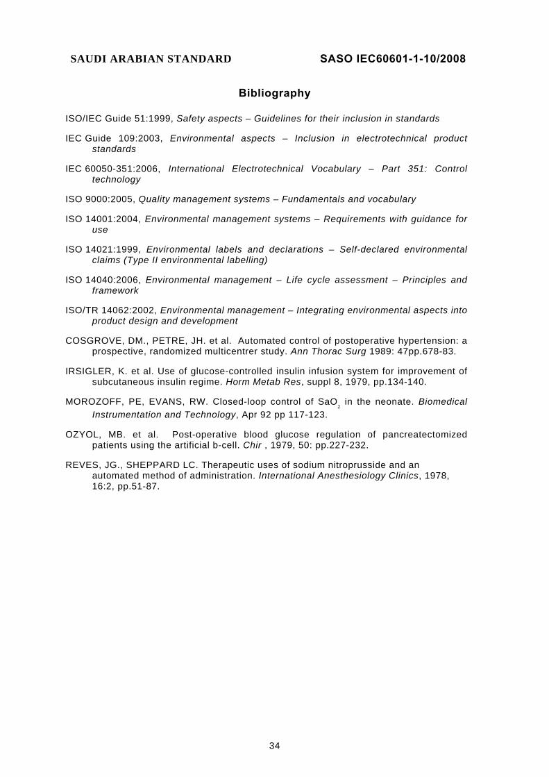
Bibliography
ISO/IEC Guide 51:1999, Safety aspects – Guidelines for their inclusion in standards
IEC Guide 109:2003, Environmental aspects – Inclusion in electrotechnical product standards
IEC 60050-351:2006, International Electrotechnical Vocabulary – Part 351: Control technology
ISO 9000:2005, Quality management systems – Fundamentals and vocabulary
ISO 14001:2004, Environmental management systems – Requirements with guidance for use
ISO 14021:1999, Environmental labels and declarations – Self-declared environmental claims (Type II environmental labelling)
ISO 14040:2006, Environmental management – Life cycle assessment – Principles and framework
ISO/TR 14062:2002, Environmental management – Integrating environmental aspects into product design and development
COSGROVE, DM., PETRE, JH. et al. Automated control of postoperative hypertension: a prospective, randomized multicentrer study. Ann Thorac Surg 1989: 47pp.678-83.
IRSIGLER, K. et al. Use of glucose-controlled insulin infusion system for improvement of subcutaneous insulin regime. Horm Metab Res, suppl 8, 1979, pp.134-140.
MOROZOFF, PE, EVANS, RW. Closed-loop control of SaO2 in the neonate. Biomedical
Instrumentation and Technology, Apr 92 pp 117-123.
OZYOL, MB. et al. Post-operative blood glucose regulation of pancreatectomized patients using the artificial b-cell. Chir , 1979, 50: pp.227-232.
REVES, JG., SHEPPARD LC. Therapeutic uses of sodium nitroprusside and an automated method of administration. International Anesthesiology Clinics, 1978, 16:2, pp.51-87.
SAUDI ARABIAN STANDARD SASO IEC60601-1-10/2008
35
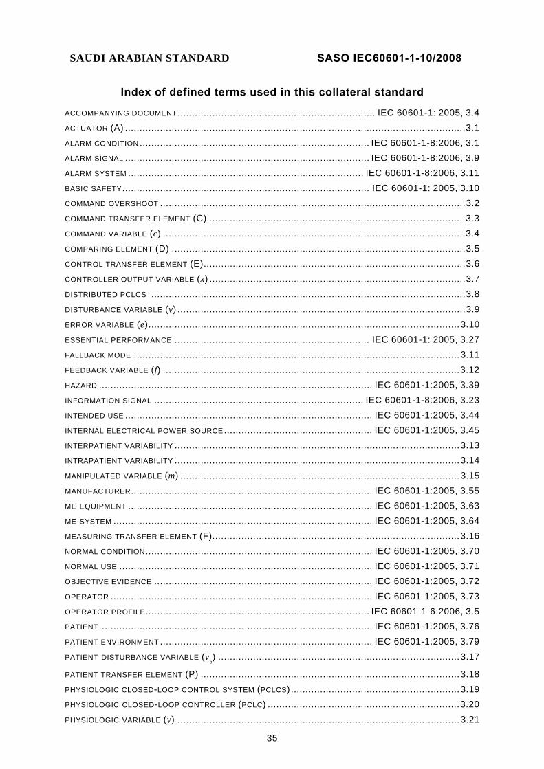
Index of defined terms used in this collateral standard
ACCOMPANYING DOCUMENT .................................................................... IEC 60601-1: 2005, 3.4 ACTUATOR (A) ..................................................................................................................... 3.1 ALARM CONDITION ............................................................................... IEC 60601-1-8:2006, 3.1 ALARM SIGNAL .................................................................................... IEC 60601-1-8:2006, 3.9 ALARM SYSTEM ................................................................................. IEC 60601-1-8:2006, 3.11 BASIC SAFETY ..................................................................................... IEC 60601-1: 2005, 3.10 COMMAND OVERSHOOT ......................................................................................................... 3.2 COMMAND TRANSFER ELEMENT (C) ........................................................................................ 3.3 COMMAND VARIABLE (c) ........................................................................................................ 3.4 COMPARING ELEMENT (D) ..................................................................................................... 3.5 CONTROL TRANSFER ELEMENT (E) .......................................................................................... 3.6 CONTROLLER OUTPUT VARIABLE (x) ........................................................................................ 3.7 DISTRIBUTED PCLCS ............................................................................................................ 3.8 DISTURBANCE VARIABLE (v) ................................................................................................... 3.9
ERROR VARIABLE (e) ........................................................................................................... 3.10 ESSENTIAL PERFORMANCE ................................................................... IEC 60601-1: 2005, 3.27 FALLBACK MODE ................................................................................................................ 3.11 FEEDBACK VARIABLE (f) ...................................................................................................... 3.12 HAZARD .............................................................................................. IEC 60601-1:2005, 3.39 INFORMATION SIGNAL ........................................................................ IEC 60601-1-8:2006, 3.23 INTENDED USE ..................................................................................... IEC 60601-1:2005, 3.44 INTERNAL ELECTRICAL POWER SOURCE ................................................... IEC 60601-1:2005, 3.45 INTERPATIENT VARIABILITY .................................................................................................. 3.13 INTRAPATIENT VARIABILITY .................................................................................................. 3.14 MANIPULATED VARIABLE (m) ................................................................................................ 3.15 MANUFACTURER ................................................................................... IEC 60601-1:2005, 3.55 ME EQUIPMENT .................................................................................... IEC 60601-1:2005, 3.63 ME SYSTEM ......................................................................................... IEC 60601-1:2005, 3.64 MEASURING TRANSFER ELEMENT (F)..................................................................................... 3.16 NORMAL CONDITION .............................................................................. IEC 60601-1:2005, 3.70 NORMAL USE ....................................................................................... IEC 60601-1:2005, 3.71 OBJECTIVE EVIDENCE ........................................................................... IEC 60601-1:2005, 3.72 OPERATOR .......................................................................................... IEC 60601-1:2005, 3.73 OPERATOR PROFILE ............................................................................. IEC 60601-1-6:2006, 3.5 PATIENT .............................................................................................. IEC 60601-1:2005, 3.76 PATIENT ENVIRONMENT ......................................................................... IEC 60601-1:2005, 3.79 PATIENT DISTURBANCE VARIABLE (v
p) ................................................................................... 3.17
PATIENT TRANSFER ELEMENT (P) ......................................................................................... 3.18 PHYSIOLOGIC CLOSED-LOOP CONTROL SYSTEM (PCLCS) .......................................................... 3.19 PHYSIOLOGIC CLOSED-LOOP CONTROLLER (PCLC) .................................................................. 3.20 PHYSIOLOGIC VARIABLE (y) ................................................................................................. 3.21

SAUDI ARABIAN STANDARD SASO IEC60601-1-10/2008
36
PROCESS ............................................................................................ IEC 60601-1:2005, 3.89 PROGRAMMABLE ELECTRICAL MEDICAL SYSTEM (PEMS) ............................. IEC 60601-1:2005, 3.90 PROGRAMMABLE ELECTRONIC SUBSYSTEM (PESS) .................................... IEC 60601-1:2005, 3.91 RECORD .............................................................................................. IEC 60601-1:2005, 3.98 REFERENCE VARIABLE (w) ................................................................................................... 3.22
RELATIVE OVERSHOOT (yro) ................................................................................................. 3.23
RESIDUAL RISK .................................................................................. IEC 60601-1:2005, 3.100 RESPONSE TIME (T
r) ........................................................................................................... 3.24
RISK ................................................................................................. IEC 60601-1:2005, 3.102 RISK ANALYSIS ................................................................................... IEC 60601-1:2005, 3.103 RISK MANAGEMENT ............................................................................. IEC 60601-1:2005, 3.107 RISK MANAGEMENT FILE ...................................................................... IEC 60601-1:2005, 3.108 SERVICE PERSONNEL .......................................................................... IEC 60601-1:2005, 3.113 SETTLING TIME (T
st) ............................................................................................................ 3.25
SINGLE FAULT CONDITION .................................................................... IEC 60601-1:2005, 3.116 STEADY-STATE DEVIATION (y
sd) ............................................................................................ 3.26
SUPPLY MAINS ................................................................................... IEC 60601-1:2005, 3.120 TRACKING ERROR (E
tr) ........................................................................................................ 3.27
TRAINING ........................................................................................... IEC 60601-1-6:2006, 3.8 USE ERROR ........................................................................................ IEC 60601-1-6:2006, 3.9 USABILITY ........................................................................................ IEC 60601-1:2005, 3.136 USABILITY ENGINEERING .................................................................... IEC 60601-1-6:2006, 3.12 USABILITY ENGINEERING FILE .............................................................. IEC 60601-1-6:2006, 3.13 VALIDATION ...................................................................................... IEC 60601-1-6:2006, 3.15 VARIABLE .......................................................................................................................... 3.28 VERIFICATION .................................................................................... IEC 60601-1:2005, 3.138