Embed Size (px)
Citation preview

SAP® Smart Meter Rollout by PROLOGA
© PROLOGA GmbH User Manual Add-on 7.0
SAP® Smart Meter Rollout by PROLOGA Document Version 3
SAP® Smart Meter Rollout by PROLOGA
User Manual

SAP® Smart Meter Rollout by PROLOGA
© PROLOGA GmbH User Manual Add-on 7.0
SAP® Smart Meter Rollout by PROLOGA Document Version 3
©Copyright 2018 PROLOGA GmbH. All rights reserved. No part of this publication may be reproduced or transmitted in any form or for any purpose without the express permission of PROLOGA GmbH. The information contained herein may be changed without
prior notice. Some software products marketed by PROLOGA GmbH and its distributors may contain proprietary software components of other software vendors. Microsoft®, WINDOWS®, NT®, EXCEL®, Word®, PowerPoint® and SQL Server® are registered trademarks of Microsoft Corporation.
IBM®, DB2®, DB2 Universal Database, OS/2®, Parallel Sysplex®, MVS/ESA, AIX®, S/390®, AS/400®,
OS/390®, OS/400®, iSeries, pSeries, xSeries, zSeries, z/OS, AFP, Intelligent Miner, WebSphere®, Netfinity®, Tivoli®, Informix and Informix® Dynamic ServerTM are trademarks of IBM Corporation in USA and/or other countries. Oracle® is a registered trademark of Oracle Corporation.
UNIX®, X/Open®, OSF/1®, and Motif® are registered trademarks of the Open Group. Citrix®, ICA®, Program Neighbourhood®, Meta frame®, WinFrame®, Video Frame®, and MultiWin® are trademarks or registered trademarks of Citrix Systems, Inc.
HTML, XML, XHTML and W3C are trademarks or registered trademarks of the W3C®, World Wide Web Consortium, Massachusetts Institutes of Technology.
Java® is a registered trademark of Sun Microsystems, Inc. Javascript® is a registered trademark of Sun Microsystems, Inc., used under license for technology invented and implemented by Netscape.
MaxDB® is a trademark of MySQL OFF, Sweden. SAP, SAP Logo, R/2, R/3, mySAP, mySAP.com, and other SAP products and services mentioned herein as well as their respective logos are trademarks or registered trademarks of SAP AG in Germany and in several other countries all over the world.
All other products and service names mentioned are the trademarks of their respective companies. These materials are provided by PROLOGA GmbH for informational purposes only, without representation or warranty of any kind and PROLOGA GmbH shall not be liable for errors or omissions with respect to
the materials. These materials are subject to change without notice. The only warranties for PROLOGA products and services are those that are set forth in the express warranty statements accompanying such
products and services, if any. Nothing herein should be construed as constituting an additional warranty. National product specifications may vary. The original text of this document has been written in German. An English language translation has been provided as courtesy. In case of any conflict, it is agreed that the German version is the official original version and text and shall prevail in all respects and that no translated language shall be offered as evidence of the meaning of the German original.

SAP® Smart Meter Rollout by PROLOGA
© PROLOGA GmbH page 3 of 56
SAP® Smart Meter Rollout by PROLOGA User Manual Add-on 7.0 Document Version 3
Table of contend
1 Introduction ................................................................................................................... 6
1.1 Pre-requisites .................................................................................................................... 7 1.2 Components of the Module ................................................................................................. 8 1.3 General Concepts and Terms............................................................................................... 9
2 Definition of Terms ....................................................................................................... 10
3 Operation ..................................................................................................................... 11
3.1 General Operation ........................................................................................................... 11 3.1.1 Working with the tree structure ......................................................................................... 11 3.2 Additional Notes .............................................................................................................. 12
4 Planning Area Settings (/N/WATP/TP05) .................................................................... 13
4.1 Transaction Structure ....................................................................................................... 13 4.1.1 Menu Item Planning Area .................................................................................................. 13 4.1.2 Menu Item Edit ............................................................................................................... 14 4.1.3 Menu Item Extras ............................................................................................................ 14 4.2 Creating a Planning Aspect ............................................................................................... 16 4.3 Definition of planning related attributes .............................................................................. 16 4.4 Creating a Planning Area .................................................................................................. 16 4.5 Access Control ................................................................................................................ 17 4.6 Display Options ............................................................................................................... 17 4.6.1 Filter by Device / Container Categories ............................................................................... 20 4.6.2 Filter by Regional Structure .............................................................................................. 20
5 Configure Task Lists and Smart Meter Configuration .................................................... 21
5.1 Task List (/NIA05) ........................................................................................................... 21 5.2 Smart Meter Configuration (/N/WATP/SM_CONFIG) ............................................................. 21 5.2.1 Setting of Scheduler Integration ........................................................................................ 22 5.2.2 Used Planning Setting ...................................................................................................... 22 5.2.3 Work Plans ..................................................................................................................... 22 5.2.4 Work Plan Assignment ...................................................................................................... 23 5.2.5 Work Plan Types .............................................................................................................. 23 5.2.6 Planning Aspect ............................................................................................................... 24
6 Route District Planning (/N/WATP/TP_LONGTERM) .................................................... 25
6.1 Open Planning Area and Due Date ..................................................................................... 26 6.2 Screen Layout of the Route District Planning ....................................................................... 26 6.2.1 Menu Item Planning Scenario ............................................................................................ 26 6.2.2 Menu Item Edit ............................................................................................................... 27 6.2.3 Menu Item Extras ............................................................................................................ 27 6.3 Screen Layout Navigation Tree .......................................................................................... 27 6.3.1 Context Menu of the Navigation Tree ................................................................................. 29 6.3.2 Menu Bar of the Navigation Tree........................................................................................ 32 6.3.3 Function Toolbar of the Navigation Tree ............................................................................. 34 6.3.4 Toolbar of the navigation tree ........................................................................................... 36 6.4 Filter Selection and Search ............................................................................................... 36 6.4.1 Filter Selection ................................................................................................................ 36 6.4.2 Active Filter .................................................................................................................... 37 6.4.3 Search Filter ................................................................................................................... 38 6.4.4 Resume Search ............................................................................................................... 38 6.5 Drag & Drop in the Tree ................................................................................................... 39 6.6 Screen Layout of the Detailed Information Screen ............................................................... 40 6.6.1 Node Planning Scenario .................................................................................................... 40 6.6.2 Node Route District .......................................................................................................... 41 6.6.3 Node Planning Segments .................................................................................................. 43 6.6.4 Node Planning Elements ................................................................................................... 44 6.7 Map ............................................................................................................................... 46 6.7.1 Map Functions in the Function Bar ..................................................................................... 46 6.7.2 Context Menu of the Map .................................................................................................. 48 6.8 Calculate Key Data .......................................................................................................... 49 6.9 Approve and Activate Route Districts and Create Work Plans ................................................. 49
SAP® Smart Meter Rollout by PROLOGA
© PROLOGA GmbH page 4 of 56
SAP® Smart Meter Rollout by PROLOGA User Manual Add-on 7.0 Document Version 3
6.10 Deadline Monitoring for Maintenance Plans ......................................................................... 50
7 Scheduler Integration (/N/WATP/TP_SCHEDULER) ..................................................... 52
7.1 Prerequisite .................................................................................................................... 52 7.2 Screen Layout ................................................................................................................. 53 7.3 Scheduling of Route Districts............................................................................................. 53
8 Tips, Tricks and FAQs ................................................................................................... 56
Table of Figures
Figure 01: Mass data challenge ...................................................................................................... 6 Figure 02: Solution ....................................................................................................................... 7 Figure 03: Relevant objects and their connections within the SAP® Smart Meter Rollout by PROLOGA
solution ................................................................................................................................. 8 Figure 04: Assign container type I ................................................................................................ 12 Figure 05: Assign container type II ............................................................................................... 12 Figure 06: Assign container type III .............................................................................................. 12 Figure 07: Structure of the planning area screen ............................................................................ 13 Figure 08: Menu item planning area .............................................................................................. 13 Figure 09: Menu item Edit ........................................................................................................... 14 Figure 10: Menu item Extras I ...................................................................................................... 14 Figure 11: Record information ...................................................................................................... 15 Figure 12: Planning Aspect .......................................................................................................... 16 Figure 13: Definition of attributes ................................................................................................. 16 Figure 14: Create planning area I ................................................................................................. 17 Figure 15: Create planning area II ................................................................................................ 17 Figure 16: Planner ...................................................................................................................... 17 Figure 17: Options I .................................................................................................................... 18 Figure 18: Planning area – Tree Options I ...................................................................................... 18 Figure 19: Planning area – Tree Options III ................................................................................... 18 Figure 20: Display district and city ................................................................................................ 18 Figure 21: Display district and hide city ......................................................................................... 19 Figure 22: Map options ............................................................................................................... 19 Figure 23: Planning options ......................................................................................................... 19 Figure 24: Assignments ............................................................................................................... 19 Figure 25: Device / Container categories ....................................................................................... 20 Figure 26: Filter by Regional Structure .......................................................................................... 20 Figure 27: General Operations Overview ....................................................................................... 21 Figure 28: Smart Meter Configuration I ......................................................................................... 21 Figure 29: Setting of Scheduler Integration ................................................................................... 22 Figure 30: Used Planning Setting .................................................................................................. 22 Figure 31: Work Plans ................................................................................................................. 23 Figure 32: Work Plan Assignments ................................................................................................ 23 Figure 33: Work Plan Types ......................................................................................................... 24 Figure 34: Planning Aspect .......................................................................................................... 24 Figure 35: Route district planning ................................................................................................. 26 Figure 36: Screen layout of the route district planning .................................................................... 26 Figure 37: Menu Route District Planning ........................................................................................ 26 Figure 38: Menu Edit ................................................................................................................... 27 Figure 39: Menu Extras ............................................................................................................... 27 Figure 40: Navigation Tree .......................................................................................................... 27 Figure 41: Move Selected Nodes ................................................................................................... 35 Figure 42: Filter selection ............................................................................................................ 36 Figure 43: Set filter planning scenario ........................................................................................... 36 Figure 44: Set filter route district ................................................................................................. 37 Figure 45: Set filter container cat. ................................................................................................ 37 Figure 46: Set filter valid from ..................................................................................................... 37 Figure 47: Active filter ................................................................................................................ 37 Figure 48: Search filter ............................................................................................................... 38 Figure 49: Search filter street ...................................................................................................... 38 Figure 50: Search filter container location...................................................................................... 38 Figure 51: Search filter planning segment ..................................................................................... 38

SAP® Smart Meter Rollout by PROLOGA
© PROLOGA GmbH page 5 of 56
SAP® Smart Meter Rollout by PROLOGA User Manual Add-on 7.0 Document Version 3
Figure 52: Cancel search ............................................................................................................. 39 Figure 53: Layout of the detailed information screen ....................................................................... 40 Figure 54: Node Planning Scenario ............................................................................................... 41 Figure 55: Node Route District ..................................................................................................... 42 Figure 56: Tab attributes ............................................................................................................. 42 Figure 57: Node Planning Segment ............................................................................................... 44 Figure 58: Node Planning Elements ............................................................................................... 44 Figure 59: Map function I ............................................................................................................ 46 Figure 60: Print options I ............................................................................................................. 47 Figure 61: Print options II ........................................................................................................... 48 Figure 62: Context menu of the map ............................................................................................ 48 Figure 63: Key Data .................................................................................................................... 49 Figure 64: Maintenance Plans....................................................................................................... 50 Figure 65: Maintenance Items ...................................................................................................... 50 Figure 66: Work Plan Number and Maintenance Item ...................................................................... 50 Figure 67: Deadline Monitoring for Maintenance Plans ..................................................................... 51 Figure 68: Maintenance Plans....................................................................................................... 51 Figure 69: Function Ready for time scheduling ............................................................................... 52 Figure 70: Scheduler................................................................................................................... 53 Figure 71: Entry Screen of Scheduler ............................................................................................ 53 Figure 72: Selection of Planning Scenario for Scheduler .................................................................. 54 Figure 74: Planned from/ to ......................................................................................................... 54 Figure 75: Scheduled Route Districts ............................................................................................. 55 Figure 76: transferred time schedule ............................................................................................ 55
Table of Tables
Table 01: Context menu of the navigation tree I ............................................................................ 29 Table 02: Context menu of the navigation tree II ........................................................................... 31 Table 03: Menu bar of the navigation tree I ................................................................................... 32 Table 04: Menu bar of the navigation tree II .................................................................................. 33 Table 05: Function toolbar of the navigation tree ............................................................................ 35 Table 06: Functions for node planning scenario .............................................................................. 41 Table 07: Functions for node route district ..................................................................................... 43 Table 08: Functions for node planning segments ............................................................................ 44 Table 09: Functions for node planning elements ............................................................................. 45
Glossary
Attention
Note

SAP® Smart Meter Rollout by PROLOGA
© PROLOGA GmbH page 6 of 56
SAP® Smart Meter Rollout by PROLOGA User Manual Add-on 7.0 Document Version 3
1 Introduction
Since January 2010 the installation of smart meters in newly constructed buildings and significantly refurbished buildings is mandatory by (European) law. A smart meter is an electronic power meter
enabling a remote meter reading. Besides power meters, smart meters can also be applied for water, gas and heat consumption readings. Data are transmitted by LAN, GPRS, GSM, PSTN or PLC.
The roll-out of smart meters is a successive, large-scale, resource and time consuming process. Due to the vast amount of required smart meter installations there is a multitude of orders that is hardly to be processed in an efficient manner. Processing all orders in one step will probably overload the system resulting in a performance collapse.
Figure 01: Mass data challenge
Divide and conquer is an approach used to reduce complexity whereas the actual tasks are split into smaller sub tasks until the single task can be handled easily. This approach is as well used in the Smart Meter Rollout solution.

SAP® Smart Meter Rollout by PROLOGA
© PROLOGA GmbH page 7 of 56
SAP® Smart Meter Rollout by PROLOGA User Manual Add-on 7.0 Document Version 3
Figure 02: Solution
This manual explains the important steps and settings required for SAP® Smart Meter Rollout by PROLOGA.
The descriptions will be supported by detailed examples and illustrations. The input values or parameters might differ from your system.
1.1 Pre-requisites
Next to an SAP®-ERP, SAP® Smart Meter Rollout by PROLOGA requires the industry solution IS-UT.
All relevant objects and their related connections are illustrated as follows:

SAP® Smart Meter Rollout by PROLOGA
© PROLOGA GmbH page 8 of 56
SAP® Smart Meter Rollout by PROLOGA User Manual Add-on 7.0 Document Version 3
Contract Account
/NCAA1
Contract Partner
/NFPP1,
/NEC50E
Move-In
/NEC50E
Device Location
/NES65
Connection
Object
/NES55
Premise
/NES60
Installation
/NES30
Material
/NIQ04
Material Type
Full Installation
/NEG31
Planning Area
/N/WATP/TP05
Route District
/N/WATP/
TP_LONGTERM
Maintenance
Plan
/N/WATP/
TP_LONGTERM
Task List
/NIA05
Figure 03: Relevant objects and their connections within the SAP® Smart Meter Rollout by PROLOGA solution
1.2 Components of the Module
The component SAP® Smart Meter Rollout by PROLOGA is based on and extends the module
SAP® Dispatching & Planning by PROLOGA.
Overview of key transaction codes
Create task list /NIA05
Create planning area /N/WATP/TP05
Create route districts /N/WATP/TP_LONGTERM
Deadline monitoring maintenance plan /NIP10
Display Order /NIW33

SAP® Smart Meter Rollout by PROLOGA
© PROLOGA GmbH page 9 of 56
SAP® Smart Meter Rollout by PROLOGA User Manual Add-on 7.0 Document Version 3
1.3 General Concepts and Terms
The component SAP® Smart Meter Rollout by PROLOGA is used for the planning of large-scale actions, such as the exchange of Ferraris meter with smart meter.
The planning is based on installed devices existing in the SAP® system. Planning finally results in the creation of a great number of SAP® CS/PM orders which in turn are a prerequisite to exchange the meters.
Planning the device exchange as well as creating orders can be done by several employees.
General procedure
Usually, the current meter types will have to be replaced by smart meter types in a larger
region (with probably thousands or hundreds of thousands of meters). This meter exchange will take place over a period of several years.
Step 1: Define the planning area
First of all, the planning areas have to be defined. As the processing of smaller planning areas is much easier to handle, it is recommended to work with smaller planning areas with a restricted number of devices to be exchanged in a certain time period.
Which criteria could be used to define the planning area?
Supply grid
The exchange is based on the existing supply network (power supply etc.)
Region
The exchange is based on the region (e.g., city center, western suburb, northern suburb etc.) in order to work these regions with different priorities.
Device category
The exchange of certain old device types has probably a higher priority than other device types.
On the other hand, you might plan the installation of the new meters per device type.
Organizational
The meter exchange might be planned based on the requirements of the executing party (e. g. subcontractors or internal company departments)
In most cases, you will probably use a combination of these criteria.
Step 2: Create device categories and general task lists
You have to create the device types for all devices (smart meters) to be installed in your SAP® system. Moreover, the general task lists for the exchange of these device types have to be created in the system.
Step 3: Create scenarios in the planning areas
At least one planning scenario is required for each planning area. Additional scenarios may be created to compare planning options.
Step 4: Create orders
When the route district planning of the activated scenario (of a planning area) is completed, the orders are generated. Once released, the districts will be locked for further editing.
Repeat steps 3 and 4 until every planning element is scheduled.

SAP® Smart Meter Rollout by PROLOGA
© PROLOGA GmbH page 10 of 56
SAP® Smart Meter Rollout by PROLOGA User Manual Add-on 7.0 Document Version 3
2 Definition of Terms
The following terms are used in the document and will have the following meaning:
Work plans
Is an element of SAP® PM that contains specific activities (task lists) and planning data.
Task list
Is an element of SAP® PM that serves as a template to create CS/PM orders?
Work plan types
Is an element of SAP® PM describing specific activity types?
(e.g. PREPARE preparation exchange, INSTALL exchange).
Work plan assignment
Is an element of SAP® PM to be used as a template for the exchange of installed (old) devices with new devices.
You can select task lists based on the old and new device type (subject to planning aspect, work plan type and priority).
A planning element can have any number of task lists.
Planning aspect
Is an element of SAP® PM and helps to process chronologically separate tasks.
The planning aspect has to be defined in TP06.
Maintenance item
Is an element of SAP® PM that describes the exchange of a single device based on the work plan
assignment.
Maintenance plan
Is an element of SAP® PM. A maintenance plan is a collection of items at a given time. A maintenance plan also describes the extent and timing of maintenance and inspection activities.
Planning area
Based on the planning the corresponding data are copied into the route district planning.
Planning areas must be assigned to a planning aspect.
Scenario
Provide a specific plan. A planning area may contain multiple scenarios.
The active scenario is the currently valid scenario for a planning area.
Route district
A freely definable object in planning that may represent a region, a period etc. Planning elements are assigned to a route district. Moreover, settings valid for all planning elements are defined (e.g. device type, exchange date, allocated workplace etc.).
Route districts may form a hierarchy.
Planning element
Represent a certain object that can be planned. The planning element is linked to a device and a device location. It contains information on the validity, the executing entity and activity points. Planning elements are created by data import.
Planning segment
A freely definable object in planning that may represent a region, a period etc.
Planning elements are assigned to a planning segment. Moreover, settings valid for all planning elements are defined (e.g. device type, exchange date, allocated workplace etc.).

SAP® Smart Meter Rollout by PROLOGA
© PROLOGA GmbH page 11 of 56
SAP® Smart Meter Rollout by PROLOGA User Manual Add-on 7.0 Document Version 3
3 Operation
3.1 General Operation
SAP® operation standards apply for the handling of the SAP® Mobile Order Management by PROLOGA.
The following functions may be applied generally:
New/Create - creates a new entry
Edit/Change – the data of a record may be changed
View/Display – the data of a record are displayed
Delete - the entry will be deleted
New allocation – adds a subentry to a main entry
Delete allocation – deletes a subentry of a main entry
Expand/Maximize – additional fields will be displayed on a mask
Displays the dialog to start a new selection (not available in all transactions)
Displays/Hides map (if map is available)
Updates display of data records after changes
All nodes are closed
Hides all child nodes that have no data allocated
Opens a menu to select an alternative tree view
Clicking on the list next to the filter symbol opens a context menu where you can select from a
list of default filter criteria. SAP® standard filter functionalities are available.
Search clicking on the list next to the search symbol opens a context menu where you can select
from a list of default search criteria. SAP® standard search functionalities are available.
You may activate/deactivate the expert mode for enhanced settings.
In most areas a tree diagram was chosen to provide the user with a clear data overview. Whereas on the left screen side all equivalent elements are listed, a detailed view of a selected node is given on the right screen side (provided that detailed data are available).
3.1.1 Working with the tree structure
In order to open or close a node in a tree, click on the respective triangle symbol in front of the entry
(using the left mouse button). After opening a node, all allocated child nodes will be displayed. (the triangle changes from pointing to the right to pointing downwards). A triangle in front of an entry always indicates that there are further data available.

SAP® Smart Meter Rollout by PROLOGA
© PROLOGA GmbH page 12 of 56
SAP® Smart Meter Rollout by PROLOGA User Manual Add-on 7.0 Document Version 3
The node is closed analogous to opening a tree node. Click on the triangle symbol pointing downwards in front of an entry (using the left mouse button). The symbol now turns from pointing downwards to pointing to the right. The subentries are not shown any longer. It is possible to close all nodes at once
When selecting a record in the tree structure on the left side, the detailed data of this record are displayed on the right screen side.
3.2 Additional Notes
The follow-up dialog of the described context menu allows a single as well as a multiple selection of objects.
Figure 04: Assign container type I
If you click on the button Multiple Selection, the respective search dialog will open. Press enter to display the available data in list format
Figure 05: Assign container type II
and the associated multiple choice.
Figure 06: Assign container type III

SAP® Smart Meter Rollout by PROLOGA
© PROLOGA GmbH page 13 of 56
SAP® Smart Meter Rollout by PROLOGA User Manual Add-on 7.0 Document Version 3
4 Planning Area Settings (/N/WATP/TP05)
The planning area defines which services are to be planned in the route district planning.
Therefore, you have to define which devices categories, regions, map options and planning aspects are to
be planned.
In addition, you can define the settings of the SAP® menu tree in the tree options of the TP LONG TERM.
The entries define which data are to be copied to the route district planning.
4.1 Transaction Structure
Figure 07: Structure of the planning area screen
1 – Tree displaying planning area
2 – General information on the selected node
3 – Detailed information on the selected node
4.1.1 Menu Item Planning Area
Figure 08: Menu item planning area
New
A new planning area is created.
Edit
A selected planning area can be edited.
Save
This function is activated if the screen is in edit mode. Changes can be saved.
Delete
SAP® Smart Meter Rollout by PROLOGA
© PROLOGA GmbH page 14 of 56
SAP® Smart Meter Rollout by PROLOGA User Manual Add-on 7.0 Document Version 3
A planning area is marked with a deletion flag, and will no longer be displayed in the tree.
Exit
The transaction is closed.
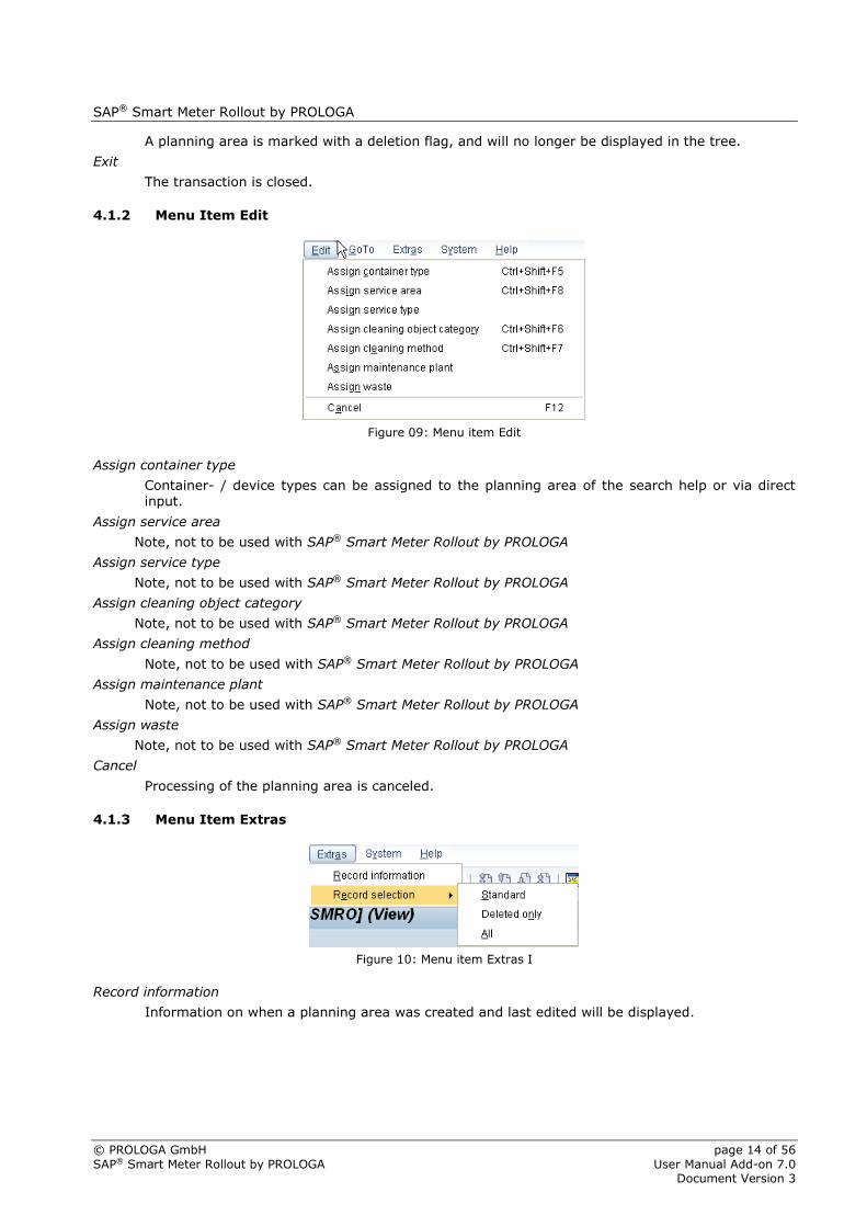
4.1.2 Menu Item Edit
Figure 09: Menu item Edit
Assign container type
Container- / device types can be assigned to the planning area of the search help or via direct input.
Assign service area
Note, not to be used with SAP® Smart Meter Rollout by PROLOGA
Assign service type
Note, not to be used with SAP® Smart Meter Rollout by PROLOGA
Assign cleaning object category
Note, not to be used with SAP® Smart Meter Rollout by PROLOGA
Assign cleaning method
Note, not to be used with SAP® Smart Meter Rollout by PROLOGA
Assign maintenance plant
Note, not to be used with SAP® Smart Meter Rollout by PROLOGA
Assign waste
Note, not to be used with SAP® Smart Meter Rollout by PROLOGA
Cancel
Processing of the planning area is canceled.
4.1.3 Menu Item Extras
Figure 10: Menu item Extras I
Record information
Information on when a planning area was created and last edited will be displayed.

SAP® Smart Meter Rollout by PROLOGA
© PROLOGA GmbH page 15 of 56
SAP® Smart Meter Rollout by PROLOGA User Manual Add-on 7.0 Document Version 3
Figure 11: Record information
Record selection / Standard
Only non-deleted planning areas will be displayed in the tree.
Record selection / Deleted only
All planning areas marked with a deletion flag will be displayed in
the tree.
Record selection / All
All planning areas are displayed in the tree.

SAP® Smart Meter Rollout by PROLOGA
© PROLOGA GmbH page 16 of 56
SAP® Smart Meter Rollout by PROLOGA User Manual Add-on 7.0 Document Version 3
4.2 Creating a Planning Aspect
Enter transaction code /N/WATP/TP06 in the commando field and confirm your entry.
Click on in order to create a new planning aspect.
Figure 12: Planning Aspect
The planning aspects are required for transaction SM_CONFIG as well as for TP05 (see also chapter 4.6
and 5.2.4).
4.3 Definition of planning related attributes
It is possible to add planning related attributes to a planning aspect (see chapter 4.2). They can be used as further classification of planning elements and can also be taken into account for calculation of performance points.
Figure 13: Definition of attributes
4.4 Creating a Planning Area
Enter transaction code /N/WATP/TP05 in the commando field and confirm your entry.
Click on in order to create a new planning area.

SAP® Smart Meter Rollout by PROLOGA
© PROLOGA GmbH page 17 of 56
SAP® Smart Meter Rollout by PROLOGA User Manual Add-on 7.0 Document Version 3
Figure 14: Create planning area I
Enter a new unique name in the input field Planning area and click on .
The new planning area is automatically displayed in the tree and changed to edit mode.
Figure 15: Create planning area II
Basic data for the planning area are:
Planning area: Unique technical identifier for the planning area (only for display)
Name: Name of the planning area
Description: Description of the planning area (optional)
Finally, save your data with click on .
4.5 Access Control
Tab: Planner
Here, you can define that a planning area is only to be accessed by a pre-defined group of users.
Figure 16: Planner
4.6 Display Options
Tab: Options
The tab Options contains the following field groups: Tree options, Planning options and Map options.

SAP® Smart Meter Rollout by PROLOGA
© PROLOGA GmbH page 18 of 56
SAP® Smart Meter Rollout by PROLOGA User Manual Add-on 7.0 Document Version 3
Figure 17: Options I
Tree options
With these additional selection criteria you can control the behavior and display of nodes and
child nodes within the navigation tree.
The display of each node in the navigation tree can be defined as to the following criteria: display, view and open, hide.
Figure 18: Planning area – Tree Options I
Choices:
Display
Data of the selected node are displayed.
View and open
Data of the selected node is displayed and the next child nodes are opened.
Hide
The elements of the selected node will not be displayed.
Figure 19: Planning area – Tree Options III
Figure 20: Display district and city

SAP® Smart Meter Rollout by PROLOGA
© PROLOGA GmbH page 19 of 56
SAP® Smart Meter Rollout by PROLOGA User Manual Add-on 7.0 Document Version 3
Figure 21: Display district and hide city
Map options:
The functions on the tab Map Options, allow you to define the map that is to be used for
the planning area in the Route District Planning (transaction /N/WATP/TP_LONGTERM).
Transaction /N/WATP / MAP_CONFIG allows you to define general map settings.
Figure 22: Map options
Planning options
This field group is not to be used when applying SAP® for Utilities Smart Meter Rollout by PROLOGA.
Figure 23: Planning options
Assignments
The Implementation field is not to be used when applying SAP® for Utilities Smart Meter Rollout by PROLOGA.
However, defining a planning aspect helps you to process tasks with different time frames.
Figure 24: Assignments

SAP® Smart Meter Rollout by PROLOGA
© PROLOGA GmbH page 20 of 56
SAP® Smart Meter Rollout by PROLOGA User Manual Add-on 7.0 Document Version 3
The import functionality of the route district planning is controlled by the settings defined for the planning area. The import creates planning elements within a scenario for the devices (equipments) found in the system.
You can define filter as to the device types and device locations.
4.6.1 Filter by Device / Container Categories
Tab: Device / Container categories
On tab Device / Container categories you can maintain the device categories of the planning area.
These data will be taken into account when the data are copied to the route district planning. If you do not specify any device / container categories, all device categories of the route district area will be displayed.
Figure 25: Device / Container categories
4.6.2 Filter by Regional Structure
Tab: Regions
On tab Regions, you can maintain the region data of a planning area used in route district planning.
These data will be taken into account when the data are copied to the route district planning.
If you do not specify any regions, all devices/container categories of all regions are taken into account during the import.
Figure 26: Filter by Regional Structure

SAP® Smart Meter Rollout by PROLOGA
© PROLOGA GmbH page 21 of 56
SAP® Smart Meter Rollout by PROLOGA User Manual Add-on 7.0 Document Version 3
5 Configure Task Lists and Smart Meter Configuration
Device exchange orders are generated based on work plan assignments. A work plan assignment defines the processes and materials required to execute an order. Work plan assignments are only in exceptional
cases directly assigned on planning element level.
The dispatcher/user defines which device category is to be installed in a certain area and if there are other activities (INSTALL, POSTPROCESS etc.) to be executed. Based on the configurations described in the following, the software will then automatically add the respective work plan assignment or work plan number to the device.
5.1 Task List (/NIA05)
Enter transaction code /NIA05 in the command line and confirm your entry.
In this transaction you can– if authorized by the planner group – create the task lists. These task lists contain detailed information on each single activity step (de-installation of the old device, installation of new device, configuration of the new device etc.), the labor input as well as the usual time required for the work.
Figure 27: General Operations Overview
The data defined in the columns Work and Duration are required to determine activity points, maintenance plans and items later on.
5.2 Smart Meter Configuration (/N/WATP/SM_CONFIG)
Enter transaction code /N/WATP/SM_CONFIG in the command line and confirm your entry.
Figure 28: Smart Meter Configuration I
In transaction WATP/SM_CONFIG you can create work plans, define work plan assignments and work
plan types.
Click on or press (F7) in order to create a new work plan, work plan assignment or work plan type.

SAP® Smart Meter Rollout by PROLOGA
© PROLOGA GmbH page 22 of 56
SAP® Smart Meter Rollout by PROLOGA User Manual Add-on 7.0 Document Version 3
5.2.1 Setting of Scheduler Integration
Here it can be specified which 2 levels of Longterm Planning will be displayed in the scheduler.
Following settings can be done:
Level for resource group: Which route district level will be displayed as main group in the scheduler.
Example: 1 = 1st Route district level
Level for resource: Which route district level will be displayed as sub group in the scheduler.
Example: 2 = 2nd Route district level
Figure 29: Setting of Scheduler Integration
5.2.2 Used Planning Setting
Here the used planning setting for the scheduler can be set (transaction /WATP/TP_SCHEDULER).
Following planning settings are available in standard:
WEEKVIEW
MONTHVIEW
Figure 30: Used Planning Setting
5.2.3 Work Plans
The task list for each CS-order is created based on the work plans.

SAP® Smart Meter Rollout by PROLOGA
© PROLOGA GmbH page 23 of 56
SAP® Smart Meter Rollout by PROLOGA User Manual Add-on 7.0 Document Version 3
Figure 31: Work Plans
Based on the work plan types, planning data and the task list you can define several work plans.
According to the selected work plan type, the work plans can be used for various activities (e.g. INSTALL, POSTPROCES, PREPARE, etc.).
5.2.4 Work Plan Assignment
The work plan assignment assigns a meter to a work plan (based on the characteristics defined for the meter). If there are several assignments possible, the given priority will be the decisive factor.
Device types, work plans and work plan types can be assigned to different planning aspects (e.g. CLEANING, INSPECTION, DEV_CHANGE).
Figure 32: Work Plan Assignments
Entering an installed device type will select the task list on a more detailed level.
5.2.5 Work Plan Types
Here, you can define work plan types for several sub-tasks.

SAP® Smart Meter Rollout by PROLOGA
© PROLOGA GmbH page 24 of 56
SAP® Smart Meter Rollout by PROLOGA User Manual Add-on 7.0 Document Version 3
Figure 33: Work Plan Types
5.2.6 Planning Aspect
Planning aspects have to be defined in TP05.
Figure 34: Planning Aspect
The planning areas of a planning aspect define the same function while splitting it into manageable pieces.
A device can only be planned for all planning areas of a planning aspect.
SAP® Smart Meter Rollout by PROLOGA
© PROLOGA GmbH page 25 of 56
SAP® Smart Meter Rollout by PROLOGA User Manual Add-on 7.0 Document Version 3
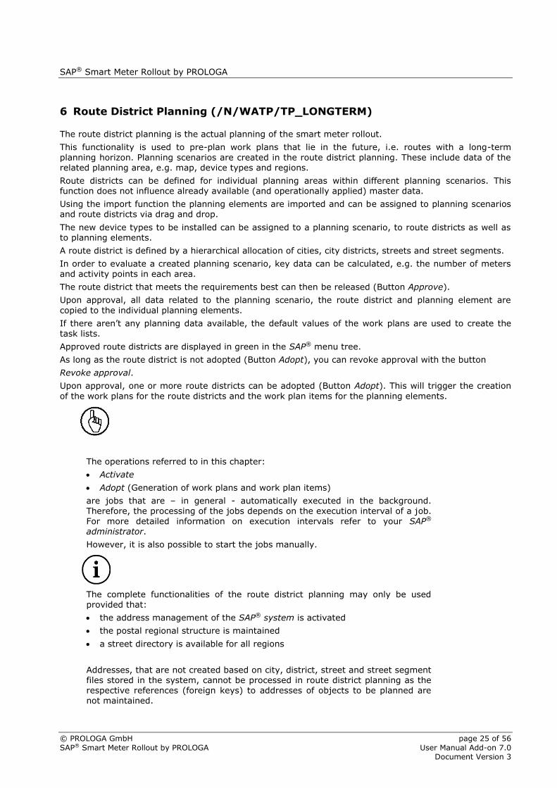
6 Route District Planning (/N/WATP/TP_LONGTERM)
The route district planning is the actual planning of the smart meter rollout.
This functionality is used to pre-plan work plans that lie in the future, i.e. routes with a long-term
planning horizon. Planning scenarios are created in the route district planning. These include data of the related planning area, e.g. map, device types and regions.
Route districts can be defined for individual planning areas within different planning scenarios. This function does not influence already available (and operationally applied) master data.
Using the import function the planning elements are imported and can be assigned to planning scenarios and route districts via drag and drop.
The new device types to be installed can be assigned to a planning scenario, to route districts as well as to planning elements.
A route district is defined by a hierarchical allocation of cities, city districts, streets and street segments.
In order to evaluate a created planning scenario, key data can be calculated, e.g. the number of meters and activity points in each area.
The route district that meets the requirements best can then be released (Button Approve).
Upon approval, all data related to the planning scenario, the route district and planning element are
copied to the individual planning elements.
If there aren’t any planning data available, the default values of the work plans are used to create the task lists.
Approved route districts are displayed in green in the SAP® menu tree.
As long as the route district is not adopted (Button Adopt), you can revoke approval with the button
Revoke approval.
Upon approval, one or more route districts can be adopted (Button Adopt). This will trigger the creation
of the work plans for the route districts and the work plan items for the planning elements.
The operations referred to in this chapter:
Activate
Adopt (Generation of work plans and work plan items)
are jobs that are – in general - automatically executed in the background. Therefore, the processing of the jobs depends on the execution interval of a job.
For more detailed information on execution intervals refer to your SAP® administrator.
However, it is also possible to start the jobs manually.
The complete functionalities of the route district planning may only be used provided that:
the address management of the SAP® system is activated
the postal regional structure is maintained
a street directory is available for all regions
Addresses, that are not created based on city, district, street and street segment files stored in the system, cannot be processed in route district planning as the respective references (foreign keys) to addresses of objects to be planned are not maintained.

SAP® Smart Meter Rollout by PROLOGA
© PROLOGA GmbH page 26 of 56
SAP® Smart Meter Rollout by PROLOGA User Manual Add-on 7.0 Document Version 3
6.1 Open Planning Area and Due Date
Enter transaction code /N/WATP/TP_LONGTERM in the commando field and confirm your entry. Then, select a planning area.
Figure 35: Route district planning
Now, select a planning area for the route district planning.
6.2 Screen Layout of the Route District Planning
Figure 36: Screen layout of the route district planning
1 – Tree displaying planning area with planning scenario, route district and planning elements.
4 – Detailed information of the selected node
6.2.1 Menu Item Planning Scenario
Figure 37: Menu Route District Planning
Depending on the selected node, the menu items change in the menu bar (see also chapter 6.2.3)

SAP® Smart Meter Rollout by PROLOGA
© PROLOGA GmbH page 27 of 56
SAP® Smart Meter Rollout by PROLOGA User Manual Add-on 7.0 Document Version 3
6.2.2 Menu Item Edit
Figure 38: Menu Edit
Filter: Filters data in the navigation tree based on different filter criteria.
Search: Searches for data in the navigation tree based on different search criteria.
Cancel: Cancels the current action.
6.2.3 Menu Item Extras
Figure 39: Menu Extras
See chapter 4.1.3 for a description of the functions record information and record selection.
Compare to active scenario
This function is only provided on planning scenario level and is used to ensure data consistency.
The (new) scenario is compared to the active scenario.
Already adopted (Button Adopt) route districts and planning elements are copied into the (new)
scenario. Not yet scheduled planning elements can be scheduled in the (new) scenario.
To work with the (new) scenario, click the button Activate.
Now the new scenario is the active scenario (is displayed in green in the SAP® menu tree).
Create Plans
This function is only provided on planning scenario level.
With this option you can create work plans and work plan items for accepted route districts.
6.3 Screen Layout Navigation Tree
Figure 40: Navigation Tree
The following hierarchy is displayed (display depends on configuration):
<Planning scenario>
<Route district>
<City>
<District>
<Street>

SAP® Smart Meter Rollout by PROLOGA
© PROLOGA GmbH page 28 of 56
SAP® Smart Meter Rollout by PROLOGA User Manual Add-on 7.0 Document Version 3
<Planning segment>
<Planning element>
A route district can have several sub-districts. There may be several city districts
in one route district.

SAP® Smart Meter Rollout by PROLOGA
© PROLOGA GmbH page 29 of 56
SAP® Smart Meter Rollout by PROLOGA User Manual Add-on 7.0 Document Version 3
6.3.1 Context Menu of the Navigation Tree
The following functions are available in the trees context menu:
Context menu Description
Refresh (tree) The data in the tree are updated. Hidden empty folders are displayed again. The child nodes are closed.
Create planning scenario Creates a planning scenario with a due date within the currently selected planning area. The created planning scenarios are allocated to the planning area.
Create route district Creates a route district within a planning scenario.
Display planning scenario The selected scenario will be displayed.
Filter With this function you can filter data in the navigation tree based on different filter criteria.
Search With this function you can search data in the navigation tree based on different search criteria.
Display position The district will be displayed on the map.
Zoom in The selected route district is center-displayed. The map segment is enlarged.
Show district area The selected district is displayed on the map (in color if allocated).
Hide district area The selected district is masked on the map.
Edit Edit district area District dimensions may be defined on the map based on a closed traverse. Apply the Edit district area function in order to move, add or delete digitized points. The digitized district is displayed as transparent area.
Edit Calculate and
process district borders
District dimensions may be defined on the map based on a closed traverse. Apply the Edit district area function in order to move, add or delete digitized points. The district borders are then re-calculated. The digitized district is displayed as transparent area.
Edit Set basing point Sets the reference point for a polygon.
Edit Cut Cuts object.
Edit Insert Inserts object.
Select color The route district and the planning elements are displayed in the selected color.
Planning elements
Unassign excluded elements
All planning elements that lie outside the route district are removed from the allocation.
Planning elements
Assign included elements All planning elements that lie within a map section are allocated to a route district.
Planning elements Set
sequence Allows rescheduling of planning elements.
Planning segments
Unassign excluded
segments
All planning segments that lie outside a route district are removed from the allocation.
Planning segments
Assign included segments All planning segments that lie within a map section are allocated to a route district.
Geocode Geocodes planning elements
Set attributes Add attributes to all planning elements under a certain district
Cancel: Leaves the context menu
Table 01: Context menu of the navigation tree I

SAP® Smart Meter Rollout by PROLOGA
© PROLOGA GmbH page 30 of 56
SAP® Smart Meter Rollout by PROLOGA User Manual Add-on 7.0 Document Version 3
Based on the process node the following functions are available (see also Table 01):
Context menu
Without
node
Planning
scenario
Route
district City
City
District
Street Planning
segment
Planning
element
Refresh (tree) X X X X X X X
Create planning scenario
X X
Create Route District X X
View only selected scenario
X
Filter X
Search X
Display position X X X X
Zoom in X X X X X
Show district area X
Hide district area X
Edit Edit dist. area X
Edit Calculate and
process district borders
X
Edit Set basing
point X
Edit Cut X X
Edit Insert X X
Select color X
Planning elements
Unassign excluded elements
X
Planning elements
Assign included elements
X
Planning elements
Set sequence X
Planning segments Unassign
excluded segments
X
Planning segments Assign included
segments
X
Set attributes X

SAP® Smart Meter Rollout by PROLOGA
© PROLOGA GmbH page 31 of 56
SAP® Smart Meter Rollout by PROLOGA User Manual Add-on 7.0 Document Version 3
Geocode X X
Cancel: X X X X X X X X
Table 02: Context menu of the navigation tree II

SAP® Smart Meter Rollout by PROLOGA
© PROLOGA GmbH page 32 of 56
SAP® Smart Meter Rollout by PROLOGA User Manual Add-on 7.0 Document Version 3
6.3.2 Menu Bar of the Navigation Tree
Menu bar Description
Refresh The complete display is updated. Sub-nodes are closed and entries are updated.
Different <Object> When using this function you can change the planning area
Create planning scenario / New planning scenario
Creates a planning scenario within the currently selected planning area. The created planning scenarios are allocated to the route district planning.
Create Route District / Create
Creates a route district within a planning scenario.
Activate (Planning Scenario)
After comparing it to the active scenario, the new scenario can be activated and edited.
Calculate Key Data Based on the assigned work plan and the device type, the activity points and the number of devices are calculated
Import Based on the specifications in (/N/WATP/TP05) data are imported and planning elements created
View <-> Edit / Edit General data of the planning scenario, the route district, the planning section or the planning element can be edited depending on the selected hierarchical layer. (Leave the Edit-mode either by saving the changed data to the system or cancelling the transaction using the
function buttons Save or Cancel in the standard transaction toolbar.)
Check The route district is checked for possible errors
Save Changes can be saved
Delete A node in the tree is provided with a delete sign, and no longer displayed in the tree
Exit Leaves the current transaction
Table 03: Menu bar of the navigation tree I

SAP® Smart Meter Rollout by PROLOGA
© PROLOGA GmbH page 33 of 56
SAP® Smart Meter Rollout by PROLOGA User Manual Add-on 7.0 Document Version 3
Depending on the selected layer the following functions are available in the menu bar of the tree (see Table 04):
Menu bar
Without
node
Planning
scenario
Route
district City
City
District
Street Planning
segment
Planning
element
Refresh X X X X
Different <Object>
X X X X X
Create planning scenario / New planning scenario1
X
X X X X
Create Route District / Create1
Activate Planning Scenario
X X X X
Calculate Key Data
X X X X
Import X
View <-> Edit / Edit1
X X X X X X X X
Check X
Save X X X X
Delete X X
Exit X X X X X X X X
Table 04: Menu bar of the navigation tree II
SAP® Smart Meter Rollout by PROLOGA
© PROLOGA GmbH page 34 of 56
SAP® Smart Meter Rollout by PROLOGA User Manual Add-on 7.0 Document Version 3
6.3.3 Function Toolbar of the Navigation Tree
Select planning area: Planning area and due date can be selected or changed.
Refresh mask: The mask display will be updated (including map, general
information and additional information).
Display/Edit: Depending on the selected hierarchical layer, general data of the
planning scenario, the route district, the planning section or the planning element can be changed. Leave the Edit mode either by saving the changed data to or cancelling the transaction using the
function buttons Save or Cancel in the standard transaction
toolbar.
New route district
Create a new route district.
New
Create sub-districts for a certain district level.
Check
The selected node is checked for inconsistencies.
Import
The device types are imported according to the planning area.
Accept
The planning scenario is accepted on the selected due date.
Maintenance plans and items are created based on the planning data.
Ready for time Scheduling
The route district can released for schedule. The status of the route district will be changed from Created to Time scheduling. The route district can now schedule in the scheduler. (See chapter 7: Scheduler Integration (/N/WATP/TP_SCHEDULER).
Cancel Schedule
The release for scheduling is canceled. The status will be set back to Created.
Approve
Upon acceptance, all data related to the planning scenario, the route district and planning element are copied to the individual planning elements. If there aren’t any planning data available, the default values of the work plans are used to create the task list
Revoke Approval
Revoke the approval for a planning scenario.
Calculate key data
This function opens a list displaying analyzed activity points.
Hide/Show planning sections
Hides or shows planning sections on the map
Hide/Show planning elements
Hides or shows planning elements on the map
Reallocate objects
The currently selected route district, planning sections or planning
elements can be reallocated to another route district.

SAP® Smart Meter Rollout by PROLOGA
© PROLOGA GmbH page 35 of 56
SAP® Smart Meter Rollout by PROLOGA User Manual Add-on 7.0 Document Version 3
This new route district is to be selected in the dialog when starting
the function.
Figure 41: Move Selected Nodes
Close child nodes
The child nodes of the selected nodes in the navigation tree are closed.
Function toolbar
Without
node
Planning
scenario
Route
district City
City
District Street
Planning
segment
Planning
element
Refresh mask X X X X X X X X
Select planning area X X X X X X X X
Display/Edit X X X X
New route district X X
Check X X X X
Import X
Accept X
Approve X
Revoke approval X
Calculate key data X X X X X X X
Hide/Show planning sections
X X X X X X X
Hide/Show planning elements X X X X X X X
Reallocate objects X X X X X X X X
Close child nodes X X X X
Table 05: Function toolbar of the navigation tree

SAP® Smart Meter Rollout by PROLOGA
© PROLOGA GmbH page 36 of 56
SAP® Smart Meter Rollout by PROLOGA User Manual Add-on 7.0 Document Version 3
6.3.4 Toolbar of the navigation tree
Update/Refresh tree
Data in the navigation tree are updated. Child nodes are closed.
Minimize all nodes
All nodes of the navigation tree are collapsed.
Filter selection
Data in the navigation tree can be filtered based on several filter criteria.
Search
Data in the navigation tree can be searched according to several search criteria.
6.4 Filter Selection and Search
6.4.1 Filter Selection
Figure 42: Filter selection
Planning scenario filter
This function filters data in the navigation tree based on different planning
scenarios within a planning area.
Figure 43: Set filter planning scenario
Through the multiple selection function it is possible to define various filter criteria.
Route district filter
This function filters data in the navigation tree based on route districts
within a planning scenario. Only the selected route districts of a scenario
are displayed. In order to apply the multiple selection function, a planning
scenario has to be selected. If a route district is selected, the planning
scenario is given by default.

SAP® Smart Meter Rollout by PROLOGA
© PROLOGA GmbH page 37 of 56
SAP® Smart Meter Rollout by PROLOGA User Manual Add-on 7.0 Document Version 3
Figure 44: Set filter route district
Through the multiple selection function it is possible to define various filter criteria.
Dev/Cont type filter
This function filters data in the navigation tree based on the device
type. Only planning elements that match these filter criteria are displayed.
Figure 45: Set filter container cat.
Through the multiple selection function it is possible to define various filter criteria.
Valid from filter
This filter restricts the period for which data are to be displayed. It can be combined with the Container/Device type filter.
Figure 46: Set filter valid from
6.4.2 Active Filter
There is no filter set.
An active filter is illustrated by a different button design.
The filter menu displays which filter has been activated (check sign in front of entry).
Figure 47: Active filter
The function Reset filter disables all active filter criteria.

SAP® Smart Meter Rollout by PROLOGA
© PROLOGA GmbH page 38 of 56
SAP® Smart Meter Rollout by PROLOGA User Manual Add-on 7.0 Document Version 3
6.4.3 Search Filter
Figure 48: Search filter
Street filter
This function searches for street data in the navigation tree.
Figure 49: Search filter street
You can select or enter a street number in the field Street Number.
Through the multiple selection function it is possible to define various filter criteria.
Device/Cont location filter
This function searches for one or more device locations in the navigation tree.
Figure 50: Search filter container location
You can select or enter a device location in the field Device/Contloc. applying the well-known
SAP® menu functions.
Planning segment filter
This function searches for one or more planning segments in the navigation tree.
Figure 51: Search filter planning segment
6.4.4 Resume Search
There is no search criteria selected.
An active search is illustrated by a different button design.
By clicking on the left side of the button the search is resumed with the
current search criteria.
The search menu displays the selected search criteria.

SAP® Smart Meter Rollout by PROLOGA
© PROLOGA GmbH page 39 of 56
SAP® Smart Meter Rollout by PROLOGA User Manual Add-on 7.0 Document Version 3
Figure 52: Cancel search
A current search can be cancelled with the function Cancel search.
6.5 Drag & Drop in the Tree
In order to move route districts or allocate planning segments and elements to route districts you have to select them in the navigation tree. Hold the left mouse button while moving the objects to their new position and release the mouse button. This function is called Drag&Drop.
Selected objects (route districts, planning sections and elements) can also be
moved with the function Move objects.
Move route district
Select a route district in the navigation tree and hold the left mouse button while moving the
object to another route district. Release the left mouse button.
Move city
Select a city in the navigation tree and hold the left mouse button
while moving the object to another route district. Release the left mouse button.
Move city district
Select a district in the navigation tree and hold the left mouse button
while moving the object to another route district. Release the left mouse button.
Street move
Select a street in the navigation tree and hold the left mouse button while
moving the object to another route district. Release the left mouse button.
Move planning sections
Select planning sections or elements in the navigation tree and hold the
and elements left mouse button while moving the object to another route district. Release the left mouse button.
The objects are now allocated to another route district.
If a planning element is moved to another planning section, the element is
assigned to this new planning section.
Only elements of the same type can be moved simultaneously.

SAP® Smart Meter Rollout by PROLOGA
© PROLOGA GmbH page 40 of 56
SAP® Smart Meter Rollout by PROLOGA User Manual Add-on 7.0 Document Version 3
6.6 Screen Layout of the Detailed Information Screen
Figure 53: Layout of the detailed information screen
Detailed information on the selected hierarchical node is displayed on tab General (4).
By double-clicking on a planning scenario, route district, a planning section or a planning element the relevant detailed information of the selected object are displayed.
With the function View <-> Edit (click button in function bar), you can edit the data of the selected
node.
6.6.1 Node Planning Scenario
In the tab planning scenario (on planning scenario level), the field group planning scenario and the tabs General, History and Protocol are displayed.
Here, you can enter or check data.
On planning scenario level information about the status of the planning scenario is given:
Created
Planning scenario is created.
Active
Planning scenario is active. Route districts can be released, planning scenarios can be adopted.
Closed
Planning scenario is dosed. Further processing is not possible.
Apply
The planning data of the approved route district were applied to the planning scenario
Apply Stopped
Copying of the planning data from released route district was stopped.

SAP® Smart Meter Rollout by PROLOGA
© PROLOGA GmbH page 41 of 56
SAP® Smart Meter Rollout by PROLOGA User Manual Add-on 7.0 Document Version 3
Figure 54: Node Planning Scenario
Field Group Description
Planning Scenario
Contains basic data, such as the unique name, the display name, a description and the planning area.
Tab General:
Planning Data
Planning data can be entered for the planning scenario. As long as no other planning data are entered in the child nodes of the planning scenario, the entered data on scenario node level are copied to its child nodes. Planning data describe the type of orders to be created, the executing entity and the date of execution.
Here, you can enter the new device to be installed, the main work center and the date.
Tab History Important events are documented on this tab.
Tab Protocol The log displays status messages for different actions.
Table 06: Functions for node planning scenario
The field group Planning data will be displayed as well on Route district and Planning element level.
The planning data apply to all objects in the planning scenario.
However, you can define individual Planning data for route districts and planning elements.
6.6.2 Node Route District
On the tab Route district, the field groups General and Assignment and the tabs General, Maint. Plans, History and Protocol are displayed.
Here, you can enter or check data.
On route district level, information about the status of the route district is given:
Created
Route district was created.
Time Scheduling
The route district can now be scheduled.
Released
Route district was released. The planning is complete and it is possible to generate maintenance plans and items.

SAP® Smart Meter Rollout by PROLOGA
© PROLOGA GmbH page 42 of 56
SAP® Smart Meter Rollout by PROLOGA User Manual Add-on 7.0 Document Version 3
Activating
Maintenance plans and items are generated.
Active
Maintenance plans and items were generated for the route district.
On tab Route district it is possible to choose a method for the task list. You can choose between manual and automatic methods. If the automatic method is selected an appropriate maintenance plan template based on the old and new device is searched for in SM_CONFIG.
If the manual method is selected, the generation of maintenance plans is based on a specific work plan number.
Regardless of the select method for the task list the main work center and time period must be specified
because the two fields (main work center and device type resp. work plan number) define the key for the maintenance plan template assignment.
Figure 55: Node Route District
The tab Attributes is used to provide an overview of assigned attributes.
Figure 56: Tab attributes
SAP® Smart Meter Rollout by PROLOGA
© PROLOGA GmbH page 43 of 56
SAP® Smart Meter Rollout by PROLOGA User Manual Add-on 7.0 Document Version 3
The two buttons can be used to show the planning elements which have the selected attributes in the tree as well as on the map.
Field Group Description
General The field Route district displays the name of the create route district. Contains basic data, such as the unique name, the display name and a description.
Assignment The field Superior RD displays the parent route district that the selected route district is assigned to.
Tab General:
Planning Data
Planning data can be entered for the route district. As long as no other planning data are entered in child nodes of the route district, the entered data on route district level are copied to its child nodes. Planning data describe the type of orders to be created, the executing entity and the date of execution.
Here, you can enter the new device to be installed, the main work center and the period can be entered.
Tab Maint. Plans Having entered, approved and adopted the planning data the generated work plans for the selected route district will be displayed (see also chapter 6.9)
Tab History Important events are documented on this tab.
Tab Protocol The log displays status messages for different actions.
Table 07: Functions for node route district
The planning data as well as the device category apply to all child elements in the route district.
However, you can define individual Planning data for planning elements in each sub-level.
After Approve, the objects are locked and cannot be moved.
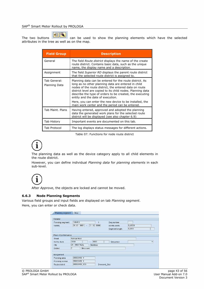
6.6.3 Node Planning Segments
Various field groups and input fields are displayed on tab Planning segment.
Here, you can enter or check data.

SAP® Smart Meter Rollout by PROLOGA
© PROLOGA GmbH page 44 of 56
SAP® Smart Meter Rollout by PROLOGA User Manual Add-on 7.0 Document Version 3
Figure 57: Node Planning Segment
Field Group Description
General
The field Planning segment displays the number of the selected planning segment. A validity period for the planning segment can be defined in field Validity. The calculated activity points will be displayed after the planning elements have been displaced in the route district.
In the display segment length, the length of the segment is displayed.
The field Seq. number is not required with SAP® Smart Meter Rollout by PROLOGA.
Place of performance
In field group Place of performance, city, district, street and house number data are displayed.
Assignment The allocation of the planning segment to a planning scenario, a planning area or route district is displayed in the respective field groups.
Table 08: Functions for node planning segments
6.6.4 Node Planning Elements
Various field groups and input fields are displayed on tab Planning element.
Here, you can enter or check data.
Data entered on planning element level will overwrite the planning data on route district level.
On tab planning element you can choose between a manual and automatic selection of task lists. If the
automatic selection is chosen, an appropriate maintenance plan template is searched for in the /N/WATP/BASE_OBJCONFIG based on the old and new device.
With the manual selection, the generation of maintenance plans is based on a specific work plan number.
Regardless of the select method for the task list the main work center and time period must be specified because the two fields (main work center and device type rsp. work plan number) define the key for the maintenance plan template assignment.
Figure 58: Node Planning Elements
Field Group Description

SAP® Smart Meter Rollout by PROLOGA
© PROLOGA GmbH page 45 of 56
SAP® Smart Meter Rollout by PROLOGA User Manual Add-on 7.0 Document Version 3
General
Contains basic data, such as the number of the planning element.
The field Seq. number is not required with SAP® Smart Meter Rollout by PROLOGA.
Location of Service
In the field group Location of service, city, district, street and house number data are displayed.
Assignment The allocation of the planning element to a route district is displayed in the field group Assignment
Tab General:
Planning Data
Planning data can be entered for the planning element.
Data entered here will overwrite planning data on route district level.
Tab General:
Device Category
In this field group the device location and the installed device are displayed.
Tab Work Plans Having entered, approved and accepted the planning data, the work plan number as well as the work plan items will be displayed (see also chapter 6.9)
Table 09: Functions for node planning elements

SAP® Smart Meter Rollout by PROLOGA
© PROLOGA GmbH page 46 of 56
SAP® Smart Meter Rollout by PROLOGA User Manual Add-on 7.0 Document Version 3
6.7 Map
Figure 59: Map function I
The map can be accessed through the second tab of the right screen.
6.7.1 Map Functions in the Function Bar
Zoom in
Minimizes the current map section in defined steps. More details are displayed.
Zoom out
Maximizes the current map section in defined steps. Less detail is displayed.
Zoom out (max.)
The map is displayed in its maximum size.
Update
The map is updated.
The functions described in the following (mouse: zoom and selection) can only be
activated one at a time. You can switch between both functions.
Mouse zoom
In order to minimize the map section, draw a rectangle while holding the left
mouse button. The drawn rectangle will be the new map display.
An active Mouse: Zoom is displayed by the following button .
Selection: Rectangle: If this function is used, a rectangle is drawn which selects the objects in
this area. If you additionally press the keys ALT, CTRL or SHIFT you can achieve the
following effects:

SAP® Smart Meter Rollout by PROLOGA
© PROLOGA GmbH page 47 of 56
SAP® Smart Meter Rollout by PROLOGA User Manual Add-on 7.0 Document Version 3
ALT
Delete objects from the selection
SHIFT
Add objects to the selection
CTRL
Invert selection (selected objects are deselected and vice versa) an active Selection
Rectangle function is displayed by the following button.
Selection Polygon
If this function is used, a polygon is drawn which selects the objects in this area.
Additional functionalities analog the Selection (Rectangle) function are available.
An active Selection: Polygon function is displayed by the following button.
Grey-in map: The map is displayed in grey scales. This function requires the application of the
operating system Windows and Internet Explorer.
Display objects as points: The device symbols are displayed as colored points. The color matches
the one of the respective route district.
Display/Hide labels
Labelling defined with the planning element can be displayed or hidden.
Back
The previous map position is displayed.
Next
The next map position – if available – is displayed.
Settings
Map-related technical settings can be defined (e.g. size of the map window).
If the window size of the map is defined, the map is displayed in this size.
In this case the map will not be adjusted to the screen size. If required, scrollbars
are displayed.
Print map segment
The current map segment including all displayed objects is printed. The following
dialog box opens:
Figure 60: Print options I
The printing title can be entered, confirm with button and the map segment will be printed.

SAP® Smart Meter Rollout by PROLOGA
© PROLOGA GmbH page 48 of 56
SAP® Smart Meter Rollout by PROLOGA User Manual Add-on 7.0 Document Version 3
Ensure that the printing of background colors and images is activated in the
Internet Explorer. (Menu Extras Options Advanced)
Figure 61: Print options II
6.7.2 Context Menu of the Map
When you click the right mouse button on the map, the context menu opens displaying the currently available functions.
Figure 62: Context menu of the map
Zoom
The current map segment can be zoomed in or out as to the given sizes.
The center of the map stays the same.
Cancel
Leave the context menu.
Additional function
If the CTRL key and left mouse button is pressed at the same time, the
map is centered where the mouse is pointing at.

SAP® Smart Meter Rollout by PROLOGA
© PROLOGA GmbH page 49 of 56
SAP® Smart Meter Rollout by PROLOGA User Manual Add-on 7.0 Document Version 3
Irrespective of the mouse mode (zoom or selection) the mouse pointer changes when positioned over a planning element. With a single click you can select the object or the planning element. If additionally the
ALT, CTRL or SHIFT key is pressed the following functions can be executed:
ALT
Removes objects from selection
SHIFT
Adds objects to selection
CTRL
Reverses selection (selected objects are deselected and vice versa)
Unlike in the selection mode only single objects or planning elements can be selected.
6.8 Calculate Key Data
Prerequisite for the calculation of activity points is a valid assignment of a task list to planning elements. Task lists can be allocated in all tree nodes that contain the device category.
If there are no planning data on planning scenario, route district or planning element level, the default values of the work plans are used to create the task lists.
Key figures can be calculated to evaluate a certain planning scenario or individual route districts. In order to calculate the key data for a complete planning scenario, you have to select the scenario in the
navigation tree and press button Calculate key data.
If the key data are to be calculated for individual route districts only, you have to select these route
districts in the navigation tree first and press button Calculate key data.
Figure 63: Key Data
6.9 Approve and Activate Route Districts and Create Work Plans
With the activation of the route districts on planning scenario level, the relevant maintenance plans and
items will be created, based on the defined device categories, work plan number main work center and the time schedule.
Prerequisite is the approval of the route districts. In order to approve a route district you have to select
the route district in the navigation tree and click on button Approve. The status of the route district will be changed into Released.
By clicking the button Revoke approval, the approval of a route district can be revoked and changes can be made.
Route districts can only be released on district and sub-district node. At first
released the sub-districts.
Finally, to save your changes press .
The activation (generation of work plans for released districts) can only be done on planning scenario level.

SAP® Smart Meter Rollout by PROLOGA
© PROLOGA GmbH page 50 of 56
SAP® Smart Meter Rollout by PROLOGA User Manual Add-on 7.0 Document Version 3
By double clicking on the planning scenario, the button Accept appears in the menu bar.
A click on button Accept starts the generation of the work plans and work plan items.
The work plans are generated in the background. The status of the planning scenario is now Apply.
If you are now selecting the route district, an overview of the generated work plans (Figure 64:
Maintenance Plans) is displayed on tab Work plans. Moreover, if you select the planning element an overview of the generated work plan items and task lists (Figure 66) is displayed.
Figure 64: Maintenance Plans
A forward navigation to the individual maintenance plans and maintenance items is possible (double click on the relevant entry).
Figure 65: Maintenance Items
Figure 66: Work Plan Number and Maintenance Item
6.10 Deadline Monitoring for Maintenance Plans
Depending on your system configuration, this step is automatically executed, e.g. during the night.
If no automation is set, the scheduling can be done with the transaction /NIP30.
If several maintenance/work plans will be scheduled at a time, you have to enter a date in the to field of the maintenance plan.
Click on or press (F8) to execute your entries. The maintenance/work plans are now scheduled.

SAP® Smart Meter Rollout by PROLOGA
© PROLOGA GmbH page 51 of 56
SAP® Smart Meter Rollout by PROLOGA User Manual Add-on 7.0 Document Version 3
Figure 67: Deadline Monitoring for Maintenance Plans
A protocol is created that lists information on the maintenance/work plans.
Figure 68: Maintenance Plans

SAP® Smart Meter Rollout by PROLOGA
© PROLOGA GmbH page 52 of 56
SAP® Smart Meter Rollout by PROLOGA User Manual Add-on 7.0 Document Version 3
7 Scheduler Integration (/N/WATP/TP_SCHEDULER)
This chapter describes how the route districts (See chapter 6: Route District Planning (/N/WATP/TP_LONGTERM)) can be scheduled in the scheduler. The scheduling is a prerequisite for
approving the route districts.
The scheduler integration provides only an improved visual functionality for
scheduling the route districts. The route districts can be still scheduled in the
Longterm Planning.
For Information about the general using of the scheduler, see SAP® Dispatching
& Planning – Operational Planning by PROLOGA – User Manual at chapter 6.
7.1 Prerequisite
In order to schedule the route districts with the scheduler it is required, that the route districts have the status Time Schedule. The status can be changed with help of function Ready for time scheduling (see
chapter 6.3.3: Function Toolbar of the Navigation Tree).
Figure 69: Function Ready for time scheduling

SAP® Smart Meter Rollout by PROLOGA
© PROLOGA GmbH page 53 of 56
SAP® Smart Meter Rollout by PROLOGA User Manual Add-on 7.0 Document Version 3
7.2 Screen Layout
Figure 70: Scheduler
1. Scheduler
2. Non-scheduled route districts
3. Main group
4. Sub group
7.3 Scheduling of Route Districts
In order to schedule the route districts, follow the steps.
1. Open transaction /N/WATP/TP_SCHEDULER.
2. Select in the start screen Longterm Planning Smart Meter Enhancement Set
Figure 71: Entry Screen of Scheduler
3. Please select the Planning Scenario and the Planning Horizon in the subsequent screen.
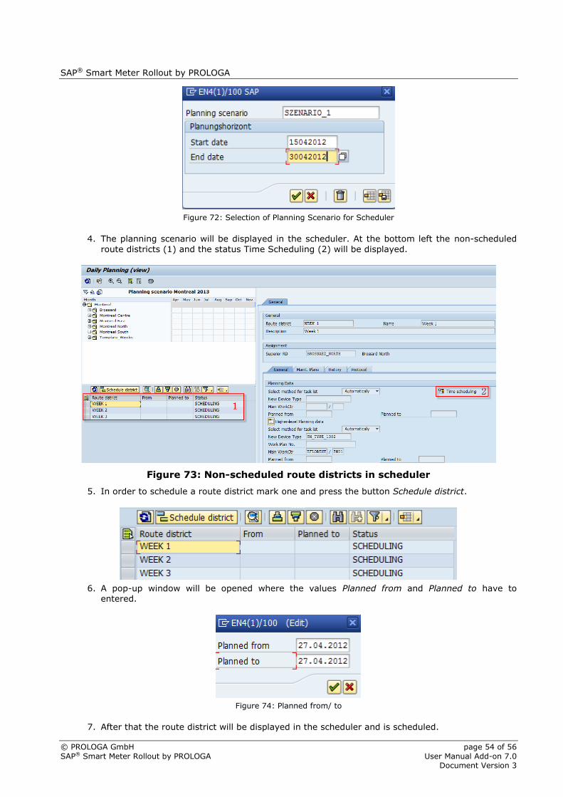
SAP® Smart Meter Rollout by PROLOGA
© PROLOGA GmbH page 54 of 56
SAP® Smart Meter Rollout by PROLOGA User Manual Add-on 7.0 Document Version 3
Figure 72: Selection of Planning Scenario for Scheduler
4. The planning scenario will be displayed in the scheduler. At the bottom left the non-scheduled
route districts (1) and the status Time Scheduling (2) will be displayed.
Figure 73: Non-scheduled route districts in scheduler
5. In order to schedule a route district mark one and press the button Schedule district.
6. A pop-up window will be opened where the values Planned from and Planned to have to entered.
Figure 74: Planned from/ to
7. After that the route district will be displayed in the scheduler and is scheduled.

SAP® Smart Meter Rollout by PROLOGA
© PROLOGA GmbH page 55 of 56
SAP® Smart Meter Rollout by PROLOGA User Manual Add-on 7.0 Document Version 3
Figure 75: Scheduled Route Districts
8. The time schedule will be transferred into the route district of the related planning scenario.
Figure 76: transferred time schedule

SAP® Smart Meter Rollout by PROLOGA
© PROLOGA GmbH page 56 of 56
SAP® Smart Meter Rollout by PROLOGA User Manual Add-on 7.0 Document Version 3
8 Tips, Tricks and FAQs
How do I create a scenario?
To create a scenario, you have to create a planning area in transaction /N/WATP/TP05. The
planning area defines the region, the already installed device categories, the planning aspect, the map settings, etc. to be applied.
Call transaction /N/WATP/TP_LONGTERM and load the planning area created in transaction /N/WATP/TP05. Go to the menu bar and call the function Create planning scenario. You can create various route districts and sub-districts within a scenario. Planning elements defined in /N/WATP/TP05 are imported with function Import data. The imported planning elements can be
allocated to various route districts, e.g. based on regional structure or other criteria.
How do I activate/apply a scenario?
To apply a scenario, the planning data have to be entered on the tab General. Data entered on parent level will override data in the relevant sublevels. Having assigned the planning elements to the route district and having entered the relevant planning data, the planning scenario can be accepted by clicking on the button Accept.
Are there any planning scenario data that cannot be changed after creation?
All technical names (e.g. scenario planning, route district) cannot be changed after they have been created because they are used as primary keys in the SAP® system. The service locations, device locations and the equipment are maintained in other transactions and therefore cannot be changed in the /N/WATP/TP_LONGTERM.
The planning data, device types, names and the specific work plans can be edited in transaction
/N/ WATP/TP_LONGTERM.
How can I define route districts?
The definition of route districts can be based on several criteria, e.g. on geographic directions or regional structures. The Smart Meter Rollout solution enables the integration of a digital map. Therefore, you will be able to import and display districts on a map in your SAP® system. You can
create route districts manually, i.e. by selecting each relevant object on the map or in the tree. However, as this will be rather time-consuming, you can as well use the polygon or rectangle function to define a district on the map.
Why aren’t there any data in the node not allocated after I have executed the function Import data?
At first, check the data (regional selection and device category) in transaction /N/WATP/TP05. If these data are correct, the data base might not be maintained correctly (e.g. Ferraris meter or
regional structure is not maintained in your SAP® system)
Or the planning elements are already scheduled.
A route district cannot be approved?
Check, if there are sub-districts assigned to a route district. Only route districts without child districts can be approved.
Do you have to enter all planning data manually?
Planning data that were maintained on parent level will be copied to their child levels after approval of the route district.
If there are no planning data on parent level maintained, the default values of the work plans are used to create the task lists.


![Smart meter-rollout -the-easter-package[1]](https://img.dokumen.tips/doc/110x75/554ac2c2b4c90524738b4b7d/smart-meter-rollout-the-easter-package1.jpg)