Embed Size (px)
Citation preview

ATSB Transport Safety ReportMarine Occurrence Investigation344-MO-2018-008Final – 14 February 2020
Loss of containers overboard from YM Efficiency16 NM east-south-east of Newcastle, New South Wales, on 1 June 2018

Cover photo: Australian Maritime Safety Authority
Released in accordance with section 25 of the Transport Safety Investigation Act 2003
Publishing information
Published by: Australian Transport Safety BureauPostal address: PO Box 967, Civic Square ACT 2608Office: 62 Northbourne Avenue Canberra, Australian Capital Territory 2601Telephone: 1800 020 616, from overseas +61 2 6257 2463 (24 hours)
Accident and incident notification: 1800 011 034 (24 hours)Email: [email protected]: www.atsb.gov.au
© Commonwealth of Australia 2020
Ownership of intellectual property rights in this publicationUnless otherwise noted, copyright (and any other intellectual property rights, if any) in this publication is owned by the Commonwealth of Australia.
Creative Commons licenceWith the exception of the Coat of Arms, ATSB logo, and photos and graphics in which a third party holds copyright, this publication is licensed under a Creative Commons Attribution 3.0 Australia licence.
Creative Commons Attribution 3.0 Australia Licence is a standard form license agreement that allows you to copy, distribute, transmit and adapt this publication provided that you attribute the work.
The ATSB’s preference is that you attribute this publication (and any material sourced from it) using the following wording: Source: Australian Transport Safety Bureau
Copyright in material obtained from other agencies, private individuals or organisations, belongs to those agencies, individuals or organisations. Where you want to use their material you will need to contact them directly.
AddendumPage Change Date

Safety summaryWhat happenedAt about 0035 on 1 June 2018, YM Efficiency was en route to Sydney, steaming slowly into strong gale force winds and very rough seas off Newcastle when it suddenly rolled heavily. As a result, 81 containers were lost overboard and a further 62 were damaged. The ship also sustained structural damage to its lashing bridges, superstructure and accommodation ladder. The ship spent a further 5 days at sea before berthing in Sydney on 6 June.
At the time of publication, searches including remote underwater surveys had identified 66 containers with a few washed ashore or close offshore. Five containers have been removed with 15 containers yet to be found. The accident resulted in substantial debris washing ashore on New South Wales beaches.
What the ATSB foundThe ATSB determined that the loss of containers overboard occurred because forces generated during the sudden, heavy rolling placed excessive stresses on containers stowed aft of the ship’s accommodation. This resulted in the structural failure of containers and components of the lashing system, leading to the loss of containers. All potential causes for the sudden rolling were investigated but there was insufficient evidence to establish a definitive reason for the rolling.
The ATSB found that the weights and distribution of containers in the affected bays were such that calculated forces exceeded allowable force limits as defined in the ship’s Cargo Securing Manual (CSM). The investigation also identified that the stowage arrangement was not checked for compliance with the CSM’s calculated lashing force limitations during the cargo planning process ashore. This left sole responsibility for compliance with these requirements with the ship’s officers, with limited options to resolve deficiencies at a late stage in the process without unduly impacting operations. Further, the officers did not use the ship’s loading computer system and its lashing calculation program to check if the stowage arrangement complied as they probably did not have an adequate understanding of the system.
What's been done as a resultThe ship’s managers, Yang Ming, now require checks of lashing forces during the initial cargo stowage planning stage ashore. Shore planners will receive regular training in the principles of cargo loading and securing, container stowage, and the dangerous goods functionality of the computer automated stowage planning software. Further, a stowage planning examination has been introduced for trainee stowage planners.
A review of loading computer systems in use across the Yang Ming fleet resulted in the adoption of class-specified, route-specific container stowage standards for part of the fleet. YM Efficiency and the other ships of the same size and type have been equipped with class-approved container stowage planning software systems, with the same software replicated ashore.
In addition, periodic training in the use of the ship’s loading computer system will be delivered to the responsible ship’s officers. Cargo procedures were also reviewed to ensure that the requirement for lashing forces checks to be conducted, both ashore and on board, was captured.
Safety messageThe safe carriage of containers at sea depends on loading, stowing and securing them in compliance with the ship’s CSM. Checking stowage plans for compliance with the CSM requirements is increasingly achieved through loading computer systems. Notwithstanding the efficiency of computerised systems, the scale and pace of modern container ship operations puts

significant pressure on ships officers to check and amend or approve proposed stowage plans at a late stage.
In that context, the planning process ashore offers the best opportunity to take all practical measures to ensure that the proposed stowage plan presented to ships officers complies with the CSM and is as safe as reasonably practicable.
Weather forecasting, routing and good navigational practices in adverse weather all play a part in minimising the risk of injuries to crew and damage to ship, cargo and environment. However, safe and effective container stowage planning remains the primary control measure in managing the risks involved in carrying containers by sea.

Contents
The occurrence.................................................................................................................1The accident 2Post-accident events 3Clean-up and response 5Detection and recovery efforts 6
Context.............................................................................................................................. 7YM Efficiency 7
Safety management system 7Weather 8
Weather routing advice 8Weather encountered 9Wave data 9Heavy weather checks 10
The container loss 10Navigation in adverse weather 10Sudden heavy rolling 11Main engine shutdown 11
Potential causes for the rolling 11Abnormal waves 12Synchronous rolling 13Parametric rolling 13Summary 14
Carriage of containers 14Container units 14Forces on containers 14
Container stowage and securing 17YM Efficiency’s CSM 17Container securing system 18Cargo operations in Kaohsiung 20Container mass-distribution arrangements 22Loading computer system 24Conduct of the lashing forces calculation check 30
Cargo-planning process 30Stowage planning centre 31Port container terminal 31Shipboard 31Rectification of identified issues 32
Incident reporting and communications 33AMSA reporting requirements 33Safety communications 34National Coast Radio Network 34
Similar occurrences 35Svendborg Maersk 35Pacific Adventurer 35Annabella 36P&O Nedlloyd Genoa 36Dutch Navigator 36

Safety analysis................................................................................................................37Container stowage and securing 37
Cargo Securing Manual 37Loading computer system 38
Cargo planning and checking 39Navigation in adverse weather 40Incident reporting and communications 40
Findings........................................................................................................................... 42Contributing factors 42Other factors that increased risk 42Other findings 42
Safety issues and actions..............................................................................................43Additional safety action 44
Yang Ming 44
General details................................................................................................................45Occurrence details 45Ship details – YM Efficiency 45
Sources and submissions..............................................................................................46Sources of information 46References 46Submissions 46
Appendices..................................................................................................................... 47Appendix A – Navigation in heavy weather or in tropical storm areas checklist 47Appendix B – Description of container positions on board 48Appendix C – Bay 52 container stowage arrangement 49Appendix D – Bay 56 container stowage arrangement 50Appendix E – Results of lashing force calculations (Force) 51Appendix F – Results of lashing force calculations (Percentage) 52Appendix G – Checklist of container stowage operation 53Appendix H – Bay 56 cargo disposition by port of loading 54
Australian Transport Safety Bureau..............................................................................55Purpose of safety investigations 55Developing safety action 55Terminology used in this report 55

› 1 ‹
ATSB – MO-2018-008
The occurrenceWhat happenedOn 13 May 2018, the 4,250 TEU1 container ship YM Efficiency sailed from Kaohsiung, Taiwan, bound for Sydney, New South Wales (NSW) (Figure 1). The ship was partly loaded, carrying 2,249 cargo containers (3,307 TEU)2 with a forward draught of 10.5 m and an aft draught of 12.5 m. The ship’s schedule required it to arrive off Sydney at 0200 Eastern Standard Time3 on 31 May.
Figure 1: YM Efficiency
Source: ATSB
During the passage south, the ship maintained an average speed of about 10 knots4 and received daily weather forecasts and routing advice from a commercial weather routing service.
On the afternoon of 28 May, YM Efficiency received instructions from the ship’s agent in Sydney to amend its arrival time to 1200 on 1 June 2018. In response, the master reduced the ship’s main engine speed to ‘slow ahead’ or 35 revolutions per minute (RPM) and the ship’s speed reduced to an average of about 8 knots.
On the afternoon of 29 May, the ship was off Brisbane, Queensland and by this time, the ship had also started receiving weather forecast information broadcast by Australia’s Bureau of Meteorology (BoM).
By 0930 on 30 May, YM Efficiency was off the coast of NSW, about 32 nautical miles5 (miles) to the north-east of Coffs Harbour. Weather forecasts received by the crew predicted steadily increasing winds and seas into the next day. The forecast estimated 4-5 m seas and swell along the NSW coast. In preparation for the expected adverse weather, the chief mate carried out checks in accordance with the ship’s heavy weather checklist. This included a check to ensure container lashings on deck were secure. The checks were completed by about 1130. By 1200, the ship was off Coffs Harbour and the weather (recorded in the ship’s logbook) was west-south-westerly winds at force 46 (between 11 and 16 knots) with 3 m seas and a 2 m swell.
At 1605, the BoM issued coastal waters forecasts for the Macquarie, Hunter and Sydney coastal regions of NSW. The forecasts included gale warnings for the next day, 31 May. The forecasts warned of 3 m seas and swell, increasing to 4 m by the evening. Other BoM forecasts, including 1 Twenty-foot Equivalent Unit, a standard shipping container. The nominal size of ships in TEU refers to the number of
standard containers that it can carry.2 As stated in the ship’s bay plans for the voyage. In addition, the ship carried four 20-foot lashing gear storage units.3 Eastern Standard Time (EST): Coordinated Universal Time (UTC) + 10 hours.4 One knot, or one nautical mile per hour, equals 1.852 kilometres per hour.5 A nautical mile of 1,852 m.6 The Beaufort scale of wind force, developed in 1805 by Admiral Sir Francis Beaufort, enables sailors to estimate wind
speeds through visual observations of sea states.

› 2 ‹
ATSB – MO-2018-008
marine wind warnings and high seas weather warnings, also warned of the developing adverse weather.
By 1900, YM Efficiency was off Port Macquarie and the weather had deteriorated. Consistent with the forecast conditions, it was recorded as being cloudy with force 8 (between 34 and 40 knots) west-south-westerly winds, 6 m seas and a 5 m swell.
By 0800 the next morning, 31 May, the ship was about 32 miles east-north-east of Port Stephens. The weather was recorded as being cloudy with west-south-westerly winds at force 8 (between 34 and 40 knots) with 7 m seas and a 5 m swell. The ship’s main engine speed remained at 35 RPM, with the ship making good about 6 knots. At about 0830, a second heavy weather checklist was completed, with the container lashings checked again. At about 1000, the ship received a weather forecast as part of the weather routing service and shortly after, BoM broadcast a coastal waters forecast. Both forecasts were consistent in predicting continuing adverse weather into the evening of 31 May.
The accidentAt about 1314 on 31 May, the agent informed YM Efficiency’s master that the required arrival time had been postponed a further 8 hours to 2000 on 1 June. At about 1400, when the ship was about 84 miles from Sydney, the master stopped the main engine and began drifting about 30 miles east of Newcastle in order to adjust the ship’s arrival time (Figure 2). The weather at the time was recorded as being overcast with west-south-westerly winds at force 8 (between 34 and 40 knots) with 6 m seas and a 5 m swell. The ship’s officers recalled that, when the ship was drifting, there was little rolling or pitching.
The main engine was re-started for brief periods over the next few hours to maintain some control over the ship’s drift. The rough weather continued into the evening with the wind recorded as west-south-westerly and strengthening to force 9 (between 41 and 47 knots) at 2200.
At about the same time, the ship’s master completed his night orders, which instructed the officer of the watch (OOW) to continue monitoring weather forecasts and the observed weather conditions. The orders required the OOW to test the main engine and other navigational equipment by 2330 before calling the master in preparation to resume the passage.

› 3 ‹
ATSB – MO-2018-008
Figure 2: Section of navigational chart Aus 489 showing YM Efficiency's track
Source: Australian Hydrographic Office, annotated by the ATSB
At about 2300, the chief engineer and duty engineer (fourth engineer) went down to man the engine room and prepare to start the main engine. Shortly before 2330, the third mate tested the engine and navigational equipment and then called the master. At about 2330, with the master on the navigation bridge (bridge), the engine was started, with the engine speed again set at ‘slow ahead’, and the passage to Sydney was resumed. The engineers left the engine room and returned to their cabins.
Shortly before midnight, having satisfied himself that the ship was on an appropriate heading, the master retired to his cabin. The master’s night orders instructed the officers to maintain 35 RPM and to use the rudder to keep the ship’s bow into the prevailing conditions to avoid a situation where the weather was on its beam.
The third mate maintained the steering in manual mode until about 2353 when he switched to autopilot with a set heading7 of 211°. At midnight, the third mate handed over the watch to the second mate. The weather at midnight was recorded as being overcast with west-south-westerly winds at force 9 (between 41 and 47 knots) with 6 m seas and a 5 m swell.
The second mate reverted to manual steering before switching back to autopilot at about 0013 on 1 June with a set heading of 210°. The ship continued to make comfortable progress (little rolling or pitching) in the prevailing conditions at a speed of about 3 to 4 knots.
Shortly after 0034, in a position about 16 miles east-south-east of Newcastle, the ship experienced a period of sudden rolling for between 60 and 90 seconds. During this period, the ship rolled quickly and heavily at least three times. The ship’s master, who was in his cabin, recalled what he believed to be a wave crashing against the ship’s side immediately before the rolling began.
According to the master and second mate, the rolling reached angles of up to 30º to port and starboard. Almost immediately after the rolling commenced, several engine room alarms sounded. In response to the rolling, the second mate changed the steering from autopilot to manual. The second mate reported hearing loud noises on deck and suspected that there had been some
7 All ship’s headings in this report are in degrees by gyrocompass with negligible error.

› 4 ‹
ATSB – MO-2018-008
container damage. He turned on the ship’s deck lights and observed that a number of containers had been damaged and possibly lost overboard from the bays aft of the accommodation. Shortly after, the main engine unexpectedly shut down, with the RPM gradually reducing to zero.
By about 0036, the rolling had subsided and the master had arrived on the bridge. The chief, second and fourth engineers went to the engine room to attend to the alarms. The second mate phoned the chief mate and alerted him to the situation. The master took over conduct of the ship’s navigation and instructed the chief mate to carry out a damage assessment.
Post-accident eventsFollowing completion of a damage assessment at about 0040, the chief mate reported several containers damaged and lost overboard from bays 52 and 56, just aft of the accommodation.
At about 0045, the engine was successfully started and the bridge engine telegraph8 set to ‘dead slow ahead’. Almost immediately however, the engine was stopped again following identification of a cracked outlet oil pipe on the control oil pump. The engineers immediately began repairs to the control oil pump. Meanwhile, the ship continued to drift in the gale force winds and seas. The master and mates reported that there was no significant rolling or pitching, and conditions on board were comfortable.
At about 0117, Newcastle vessel traffic information centre (VTIC) broadcast a safety call on very high frequency (VHF) radio channel 16.9 The associated safety message was broadcast on VHF channel 09 and consisted of a gale warning for the Hunter coastal region and weather forecast information for 1 June. The message also advised all ships drifting off Newcastle to remain more than 10 miles away from the nearest coast. YM Efficiency’s VHF radios were monitoring both of these channels.
At about 0130, the master reported the incident to the company by satellite phone. At about 0200, repairs to the control oil pump were completed. The main engine was then returned to service but was not started. By this time, the ship had settled on a heading of about 290° with the prevailing wind and seas on its port beam. The master continued to attend to internal company incident reporting and other work as the ship drifted in a northerly direction at about 2.8 knots.
At about 0229, YM Efficiency’s second mate broadcast a message on VHF channel 16. The broadcast advised that containers had been lost overboard and provided the ship’s name and the position where the containers had been lost. Two minutes later, at about 0231, the second mate broadcast another message on VHF channel 16 addressed to all stations repeating the information in the previous broadcast. This broadcast was acknowledged by another ship in the vicinity. There was no response from Newcastle VTIC or any other coast radio station.
At about 0251, Newcastle VTIC called YM Efficiency on VHF channel 09 and advised that ships drifting off Newcastle were to stay more than 10 miles from the nearest coast. At that time, YM Efficiency was 9.8 miles off the coast. The second mate acknowledged the call and advised VTIC that the ship would start its engine and move. There was no reference to the loss of containers by either party during that radio exchange. At about 0252, the main engine was started and the ship resumed the passage.
Later that morning, during daylight, the ship’s crew carried out a detailed damage assessment and attempted to stabilise the damaged and collapsed containers on deck. The damage and container loss was limited to bays 52 and 56, aft of the accommodation (Figure 3). Other damage on deck included the accommodation ladder, superstructure and lashing bridges. The crew were able to confirm that no containers carrying dangerous goods had been damaged or lost overboard.
8 An engine telegraph on a ship’s bridge is a device used to transfer orders for changes in engine speed or direction from the bridge to the engine room.
9 VHF channel 16 (156.800 MHz) is the international distress, safety and calling frequency.

› 5 ‹
ATSB – MO-2018-008
Figure 3: Damaged containers in bays 52 and 56
Source: ATSB
At about 1153, the master notified the agent in Sydney of the incident and submitted an Australian Maritime Safety Authority (AMSA) incident notification form. The agent forwarded this AMSA incident notification to the Port Authority of NSW vessel traffic service in Sydney, who in turn forwarded the notification to AMSA and Roads and Maritime Services, NSW (RMS). Subsequently, AMSA disseminated the notification and updates to others, including the ATSB. Other action initiated by AMSA included drift modelling of the lost containers and promulgating maritime safety information to alert shipping to the hazards posed by the lost and drifting containers.
At about 1440, DP World Australia10 advised the ship’s operator (Yang Ming – see the section titled YM Efficiency) that, given the potential berthing issues and scheduling delays associated with the sustained damage, YM Efficiency would not be accepted at the Port Botany terminal as originally planned. The ship then continued to steam off the coast while waiting for decisions to be taken ashore regarding its berthing.
The adverse weather conditions persisted for several days as the ship continued steaming off the south coast of NSW. However, none of the damaged or displaced containers on deck were lost overboard.
On 4 June, DP World Australia agreed to berth YM Efficiency at the Port Botany terminal early on 6 June. At about 1030 on 5 June, AMSA issued a direction to the harbour master under the Protection of the Sea (Powers of Intervention) Act 1981, directing that a suitable berth be provided to YM Efficiency by 0800 on 6 June. An AMSA direction was also issued to the ship’s owners and master directing that they make appropriate arrangements to berth the ship.
At about 0715 on 6 June, harbour pilots boarded YM Efficiency about one mile east of the Port Botany pilot boarding ground. By about 0936, the ship was securely berthed.
Over the course of the following days, representatives of many stakeholders attended YM Efficiency, including ATSB investigators, AMSA surveyors, and surveyors from the ship’s flag State. The ship was detained by AMSA following a Port State control (PSC) inspection.
10 DP World Australia, operator of the Port Botany container terminal where YM Efficiency was originally scheduled to berth.

› 6 ‹
ATSB – MO-2018-008
On 11 June, the first damaged container was discharged from the ship and by 21 June, all remaining damaged containers had been discharged. In total 81 containers were lost overboard from bays 52 and 56 and a further 62 containers on board had varying degrees of damage.
Following the completion of corrective actions required by the PSC inspection, AMSA released the ship from detention and YM Efficiency departed Sydney for Melbourne at about 2130 on 22 June.
Clean-up and responseIn the days following the container loss, AMSA along with RMS, continued to work with the ship’s owners and insurers to detect, identify and track the lost containers and their contents on the NSW coast. In accordance with NSW11 and Commonwealth12 marine environmental emergency management arrangements, RMS was designated the Combat Agency13 and assumed responsibility for responding to the incident in NSW waters. While RMS took overall charge of the response to the beached containers and debris within affected NSW waters and coastal areas, AMSA assumed responsibility for the detection of lost containers and other vessel related issues.
More than 1,000 cubic metres of incident-related debris was recovered and disposed of from affected beaches and inshore areas on the NSW coast (Figure 4). Debris from container contents was largely limited to areas of the coast in the vicinity of Port Stephens, with some debris found further north near Coffs Harbour.
Figure 4: Contents of lost containers washed ashore
Source: Roads and Maritime Services, NSW, modified by the ATSB
11 NSW State Emergency Management Plan (EMPLAN).12 National Plan for Maritime Environmental Emergencies.13 A Combat Agency is the agency identified in the State Emergency Management Plan as the agency primarily
responsible for controlling the response to a particular emergency.

› 7 ‹
ATSB – MO-2018-008
Detection and recovery effortsOn 22 June 2018, a hydrographic survey vessel engaged by YM Efficiency’s insurers began conducting a sub-sea search for the lost containers. The survey vessel identified a number of probable containers and associated debris on the sea floor. AMSA published the positions of the located containers and debris and issued updated notices to mariners warning of their location.
AMSA received at least three reports of trawlers hooking-up on containers or other material lost from YM Efficiency, which represented a risk to local fisheries and industry.
On 3 December, AMSA-contracted remotely operated underwater vehicles began an assessment of the lost containers. Several containers were identified and imaged at various locations off the NSW coast. The imagery allowed an assessment by salvage experts of the environmental risks and recovery prospects for the identified containers and debris. As of 6 May, a total area of about 578.3 square km had been searched with at least 54 of the lost containers identified. Four containers were found washed up ashore or in waters close offshore.

› 8 ‹
ATSB – MO-2018-008
ContextYM EfficiencyThe container ship YM Efficiency was built in January 2009, one of five vessels built by the Taiwan Shipbuilding Corporation (formerly known as the China Shipbuilding Corporation). At the time of the accident, the ship was owned by All Oceans Transportation, Liberia. The ship was managed and operated by Yang Ming Marine Transport Corporation (Yang Ming), Taiwan and classed with the American Bureau of Shipping (ABS).
The ship’s propulsion was provided by a Sulzer 7RT-Flex96C engine driving a single, fixed-pitch propeller, giving it a service speed of about 24.8 knots. The ship’s manoeuvring speed (normally used when navigating in ports and harbours) ranged from about 6.5 knots at ‘dead slow ahead’ to about 17 knots at ‘full ahead’.
The bridge was equipped with the necessary navigational equipment required by SOLAS14 for a ship of its size. The equipment included a Japan Radio Corporation JCY 1800 voyage data recorder (VDR).15
The ship was on a regular service between ports in China, Taiwan and Australia. The service’s southbound schedule included port calls at Ningbo, Shanghai and Shekou in China, followed by Kaohsiung, Taiwan before calling at Sydney, Melbourne and Brisbane, in that order.
YM Efficiency had a crew of 23 Chinese and Taiwanese nationals. The ship’s master was a Taiwanese national with about 18 years of seagoing experience. He held a Taiwanese and a Liberian master’s certificate of competency. This was his fifth ship as master and his first time on YM Efficiency, which he had joined about 6 months before the accident.
The chief mate was a Chinese national with about 25 years of seagoing experience. He held a Chinese chief mate’s certificate of competency and a Liberian endorsement for his certificate of competency. He had about 8 years’ experience as chief mate, all of it with Yang Ming on container ships. The chief mate had joined the ship about 6 months before the accident.
The second mate, the officer of the watch (OOW) at the time of the container loss, was also a Chinese national. He held a Chinese certificate of competency for a watch keeping officer and a Liberian endorsement for his certificate of competency. He had about 8 years’ seagoing experience, most of it with Yang Ming.
The master and chief mate had also been on board YM Efficiency in January 2018, when about 15 containers and ship’s structures sustained substantial damage in adverse weather off the Queensland coast en route to Sydney.
Safety management systemYM Efficiency held a valid safety management certificate16 issued by DNV GL (Det Norske Veritas – Germanischer Lloyd), on behalf of the ship’s flag State, Liberia, and operated under a documented safety management system (SMS). The SMS consisted of several manuals covering key aspects of the ship’s operations such as navigation safety, deck operations, shipboard management, environment protection, emergency management and engineering.
The deck manual and the shipboard management manual contained operating procedures and checklists related to container cargo operations. The SMS placed the responsibility for cargo operations on the chief mate, assisted by the master. In particular, the SMS required the
14 International Maritime Organization, 2014, The International Convention for the Safety of Life at Sea (SOLAS) 1974 as amended, IMO, London.
15 A voyage data recorder is designed to collect and store data from various shipboard systems in compliance with SOLAS requirements.
16 A safety management certificate is issued to a ship to signify that the company and shipboard management operate in accordance with the approved SMS.

› 9 ‹
ATSB – MO-2018-008
completion of a container stowage checklist for every port call, which included various checks pertaining to the safe carriage of containers on board, and ship stability.
YM Efficiency’s stability condition upon departure from Kaohsiung satisfied the International Maritime Organization’s (IMO) intact stability criteria. Yang Ming procedures required ships of YM Efficiency’s size to have a metacentric height (GM)17 of at least 0.70 m. The ship’s fluid metacentric height or GM (fluid)18 on departure Kaohsiung, and at the time of the accident, was 1.09 m.
The navigation safety manual and the shipboard management manual included the general principles and requirements for navigation. They also included procedures and checklists concerning passage planning, weather routing and navigation in heavy weather.
The relevant SMS procedure encouraged the master to make prudent use of the weather routing service. However, the procedure stated that this did not exempt the master from the responsibility of ensuring navigational safety and from collecting and analysing weather information independently. The master was also required to observe current and forecast weather and alter course and speed, if necessary, to avoid adverse weather, which could cause harm to the ship or crew. The procedure clarified that navigational decisions when adverse weather was encountered were at the master’s discretion.
The SMS also contained a checklist (Appendix A) for use when the ship was expected to navigate in heavy weather or tropical cyclones. Procedures required the checklist to be completed prior to the ship encountering heavy weather or tropical storms to ensure precautions against foreseeable hazards of the weather were taken.
WeatherWeather routing adviceYM Efficiency’s passage plan from Kaohsiung to Port Botany was planned and executed based on weather and routing advice provided by Weather News Incorporated (WNI), a commercial weather routing service.
WNI used company-specific weather safety thresholds when providing routing advice to Yang Ming ships. The WNI procedure indicated that the advice would aim to maintain the shortest distance between two ports except when certain weather conditions were encountered. The procedure required WNI to consider speed adjustments when wave heights were expected to exceed 4 m and route diversions when wave heights exceeded 6 m. When wave heights were expected to exceed 8 m, the procedure required routing advice to consider seeking shelter or drifting to avoid encountering adverse weather.
Based on the original required arrival time off the Port Botany container terminal at Sydney of 0200 on 31 May, WNI routing advice positioned YM Efficiency to track west of the forecast adverse weather and enter port before the weather worsened. On 29 May, the master informed WNI of a revised required arrival time of 1200 on 1 June with a resulting 34-hour delay in the schedule.
On 30 May, WNI acknowledged the delay in the schedule and assessed that, based on the new schedule and current forecast, the ship would not enter port before adverse weather developed. The WNI forecast predicted south-south-westerly winds increasing from force 5 (between 17 and 21 knots) to force 6 (between 22 and 27 knots) and force 7 (between 28 and 33 knots) as the ship proceeded further south. The forecast predicted significant wave heights of up to 4 m and advised the master to expect 4-5 m seas and swell. The routing advice to the master was to adjust the
17 Metacentric height is one of the critical measurements of a ship’s stability. It is usually referred to as ‘GM’, the term used for it in the equation used to calculate metacentric height.
18 GM (fluid) – a reduced GM after the free surface correction is applied to the calculated GM (GM (solid)). All ship’s GM values in this report are GM (fluid) values, with free surface effect accounted for, unless stated otherwise.

› 10 ‹
ATSB – MO-2018-008
ship’s course and speed for safety, based on actual weather conditions. The forecast and routing advice was supplemented by a phone call from WNI to confirm the master had received the warning of impending adverse weather. The master acknowledged the warning and advised that he intended to drift in a position closer to Sydney to adjust the ship’s time of arrival to align with the delayed berthing schedule.
After the accident, WNI conducted a review into the significant decisions and actions taken leading up to the master’s decision to drift. The review report stated that the master’s intention to drift was acknowledged by WNI based on the following reasoning:
the vessel was already close offshore on the east Australian coast adverse weather was expected along the east Australian coast and an immediate stoppage
might not have provided better conditions than drifting closer to Sydney there were no possible routing options that would keep the vessel clear of the developing
conditions while also maintaining the required arrival time at Sydney the master was aware of WNI’s forecast of adverse weather when he made his decision to drift the expected significant wave height in the forecast did not exceed the safety threshold for this
type of ship.
Weather encounteredThe ATSB obtained and analysed weather forecast and observation data from several sources. These included VDR data, bridge logbooks and interviews with YM Efficiency’s crew, bridge logbooks from other ships in the vicinity19 and available forecast data. The ship’s weather forecast information came primarily from WNI and the Australian Bureau of Meteorology (BoM).20
31 MayThe prevailing weather on the afternoon of 31 May, when the ship was drifting, as recorded in YM Efficiency’s bridge logbook, was west-south-westerly winds at force 8 (between 34 and 40 knots), 6 m seas and a 5 m swell. These conditions were reasonably consistent with the BoM coastal waters forecast, broadcast at 1018, 1605, 1902 and 2200 that day. The forecast warned of a complex low-pressure system moving east over the Tasman Sea; it predicted south-westerly winds between 30 and 40 knots, 4 m seas and a southerly 3 m swell. As the evening progressed, the weather deteriorated with the wind recorded as increasing to force 9 (between 41 and 47 knots) at about 2200.
Table 1 summarises the weather forecast information for 2200 on 31 May that was available to the master.
Table 1: Weather forecast informationSource Wind direction Wind speed Seas Swell
BoM forecast SW 30-40 knots 4 m 4 m (S)
WNI forecast SSW 28-33 knots 2 m 2 m (SSE)
At 2200, the master noted a south-westerly to south-south-westerly wind and a southerly swell in his night orders, which was consistent with the forecast. At about 2330, after resuming the passage, the master turned the ship to a heading of 211°, consistent with his instructions to the OOW in the night orders to keep the wind and swell on the ship’s bow.
19 Automatic identification system data indicated that there were at least eight other ships drifting or steaming at slow speed in the vicinity of YM Efficiency in the early hours of 1 June 2018.
20 All BoM coastal waters forecasts warned mariners that wind gusts could be 40 per cent stronger than averages in the forecast and that maximum wave height could be up to twice the height.

› 11 ‹
ATSB – MO-2018-008
1 JuneTable 2 summarises the observed weather data at about midnight on 31 May (0001 on 1 June), as extracted from the bridge log books on board YM Efficiency and two other ships off Newcastle at that time (Attikos and Anangel Destiny).
Table 2: Recorded weather observationsSource Wind direction Wind speed Seas Swell
YM Efficiency WSW 41-47 knots 6 m 5 m (S)
Attikos SW 41-47 knots 7 m 4 m (SW)
Anangel Destiny SSW 48-55 knots 6 m 5 m (S)
Wave dataRecorded wave data was obtained from the Port Authority of NSW and Manly Hydraulics Laboratory (MHL)21. The Port Authority’s wave rider buoys were located off Newcastle, about 16 miles west-north-west of the position where the containers were lost. The MHL buoys were located at Crowdy Head, about 84 miles north-east of that position, and at Sydney, about 65 miles south-west of the position.
The Port Authority’s buoys and MHL buoys collected significant wave height (Hsig),22 maximum wave height (Hmax),23 and wave direction24 at 10-minute and 1-hour intervals, respectively. In addition, the buoys recorded wave periods associated with, the peak of the wave energy spectrum (Tp) and the average of zero up-crossing wave periods (Tz).
Table 3 details the recorded wave data at about midnight on 31 May (0001 on 1 June) for the MHL buoys and at about 0030 on 1 June for the Newcastle buoys.
Table 3: Recorded wave data on 1 June 2018Source Time Hsig Hmax Wave direction Tp
MHL Crowdy Head 0001 4.8 m 7.3 m 181° 12.14 s
MHL Sydney 0001 4.2 m 8.5 m 187° 10.83 s
Newcastle outer buoy 0030 4.6 m 7.4 m 157° 12.12 s
0040 4.7 m 7.4 m 151° 12.96 s
Newcastle inner buoy 0030 4.7 m 7.6 m 166° 12.36 s
0040 4.8 m 7.6 m 168° 12.35 s
Heavy weather checksThe heavy weather checklist was completed on the morning of 30 May, and then again on 31 May. Some of the relevant items included in the checklist are summarised below.
Have the protection boxes of plug sockets for reefer containers been firmly closed and put under protection?
Have container lashings on deck been secured? Has course and speed been adjusted as necessary? Are weather reports being received and monitored? Are meteorological elements being observed and entered into the ship’s log?
21 Manly Hydraulics Laboratory (MHL) is a business unit within the New South Wales government’s Department of Finance, Services and Innovation. MHL’s capability includes the collection of offshore wave data.
22 Significant wave height (Hsig) is traditionally defined as being the average height of the highest one-third of the waves experienced over time. It is also referred to as ‘total wave height’. About 14 per cent or one in every seven waves will be higher than the significant wave height.
23 Maximum wave height (Hmax) can be up to twice the significant wave height. 24 The direction from which ocean waves approach a location generally represented by the direction which corresponds to
the peak period of the energy spectrum.

› 12 ‹
ATSB – MO-2018-008
The container lossOn the afternoon of 31 May, YM Efficiency was to the east of Newcastle, about 84 miles from Sydney. Prompted by the agent’s advice of a further delay to the schedule, the master assessed the situation and decided to stop and drift off Newcastle. He determined that the weather further south was worse than at the ship’s location, and that its stability condition (adjusted for arrival at Sydney) was acceptable for drifting.
Navigation in adverse weatherYM Efficiency began drifting off Newcastle at about 1400 on 1 June. The ship drifted until about 2330 that day, excluding brief periods when the main engine was used. Forecast and observed weather data for this period shows that the winds and seas were predominantly from the south-west with the swell from a direction between south-south-east and south. The weather steadily deteriorated into the evening with winds increasing to force 9 (between 41 and 47 knots) with 6 m seas and a 5 m swell being recorded at 2200.
The evidence shows that, except for the periods when the main engine was operating, the ship predominantly remained on a west-north-westerly heading. This is consistent with the expected behaviour of a container ship in that condition settling beam-on to prevailing winds and seas when drifting. While the ship lay with the weather on the beam, the master and mates recalled that there was no significant rolling or pitching.
Drifting beam-on in heavy seas leaves a ship vulnerable to the risk of synchronous rolling (see the section titled Cause of the rolling). That condition can impose stresses on the ship’s structure and cargo such as containers and securing devices, thereby increasing the risk of cargo shifting. Cargo shift can result in damage and in the ship assuming a potentially dangerous stability condition. Cumulative stresses exerted on containers and lashings due to heavy rolling can ultimately result in the failure of the container structure and lashing equipment.
Sudden heavy rolling At about 2330 on 31 May, YM Efficiency’s passage to Sydney was resumed with the ship making comfortable progress, at slow speed, with little rolling or pitching. Shortly after 0034 on 1 June, the ship rolled heavily, with containers being damaged and lost overboard, followed by the main engine shutdown. Interviews with the ship’s officers indicated that the rolling was sudden.
The second mate reported that the ship rolled about four times, that is two times to either side, and that the rolling was quick. He estimated that the rolling reached angles of up to 30° to either side. The second mate also indicated that it was likely that the ship rolled to port first but that the subsequent roll to starboard was larger. The master stated that the ship was struck by a wave, that it rolled heavily three times to angles of up to 30° and that the rolling lasted about a minute. The main engine alarms and subsequent shutdown also occurred during this period of rolling.
Analysis of VDR data, including audio data, indicated the following sequence of events (Table 4).
Table 4: Sequence of eventsTime on 1 June 2018 Event
0034:28 Estimated start of rolling
0034:50 Engineering alarms began to sound
0035:00 Rolling intensified
› 13 ‹
ATSB – MO-2018-008
0035:12 Estimated start of container loss overboard
0035:28 Steering changed from autopilot to manual
0035:38 Main engine shutdown and RPM reduces to zero
0036:00 Estimated end of container loss overboard
0036:45 Rolling subsidedSource: ATSB analysis of YM Efficiency’s VDR data
The master and second mate reported that the rolling subsided shortly after the container loss. Weather conditions after the accident remained rough and the ship settled on a north-westerly heading, drifting beam-on to the prevailing weather but with no significant rolling or pitching reported.
Main engine shutdownEngine room alarms sounded on YM Efficiency’s bridge soon after the rolling commenced. Alarm log data shows that the first alarms were cascade tank and expansion tank low-level alarms. Almost immediately afterwards, the main engine slowdown and shutdown pre-warning alarms sounded, followed by the main engine shut down and RPM gradually reducing to zero. The shutdown was accompanied by main bearing and piston lubricating oil low pressure alarms.
In the course of re-starting the main engine, both main engine control oil pumps were unserviceable for different reasons. As a result, the ship was left without propulsion until one of the pumps could be returned to service. Repairs continued until 0200 when the main engine was made available for use again. However, although the engine was available, the master decided to continue drifting.
At about 0252, Newcastle vessel traffic information centre (VTIC) called YM Efficiency with a reminder that ships were to stay greater than 10 miles from the coast when drifting, and that the ship was now 9.8 miles from the coast. Immediately after, the engine was started and the ship’s passage was resumed.
Potential causes for the rollingYM Efficiency’s dynamic roll or pitch acceleration data was not recorded on board nor was there any requirement to record such data. As such, estimates of the ship’s rolling and movement were based on other evidence. The ship’s bridge was equipped with an analogue inclinometer,25 which displayed the angle of the ship from the vertical, and registered the maximum angles reached to either side (Figure 5). Examination of the inclinometer after the ship berthed in Sydney indicated that the ship rolled to a maximum of about 29° to starboard and about 28° to port, which was consistent with the officers’ accounts of the accident. However, it was impossible to confirm if these roll angles were reached on the night of the accident.
25 Inclinometer: A device used to measure the angle of a ship’s list or heel.

› 14 ‹
ATSB – MO-2018-008
Figure 5: Inclinometer
Note semi-fixed indicators show the maximum roll encountered.Source: ATSB
The roll response of a ship in seas is determined primarily by wave-induced rolling moments,26 the natural roll period of the ship27 and the wave period.28
The roll period is largely dependent on the ship’s GM. A ship with a relatively large GM will require larger moments to incline and, when inclined, will return to the upright more quickly. Consequently, the roll period is relatively short and the ship may roll quickly and violently. A ship in such a condition is referred to as ‘stiff’. A ship with a relatively small GM will be much easier to incline and the roll period may be comparatively long. A ship in such a condition is ‘tender’.
At the time of the container loss, the ship’s stability condition had been adjusted in preparation for arrival at Sydney. The ship had been appropriately ballasted to bring it into alignment with the planned arrival stability condition, with draughts of 10.3 m forward and 12.6 m aft, and a planned arrival GM of 1.09 m. The ship’s planned arrival condition also complied with the IMO intact stability criteria.
The ship’s roll period (calculated by the loading computer system) was 20.1 s, which was consistent with the ATSB’s calculated value of about 20 s. This is generally considered an acceptable roll period resulting in a roll behaviour that is associated with neither a stiff nor a tender condition.
Extreme roll behaviour can also result from resonance, which is the phenomenon of a ship building up extreme rolling amplitudes by the addition of roll excitation loads. This can result in ‘normal’ synchronous rolling and ‘non-linear’ parametric rolling. Consistent with the master’s recollection, the ATSB also considered the possibility that the rolling was due to an abnormal or ‘rogue’ wave.
Abnormal wavesThe master stated his belief that, immediately before the accident, a large, ‘freak wave’, struck YM Efficiency and initiated the heavy rolling.
Abnormal waves, sometimes referred to as ‘rogue waves’, are very large waves that can occur at sea. Abnormal waves may occur anywhere in the world where appropriate conditions arise. A well-documented example was the 26 m wave that struck the Draupner oil platform off the coast of Norway in January 1995.
Where seas and/or swell are reinforced by waves of another wave system or where seas are influenced by a combination of two or more weather systems acting together, abnormal waves
26 The moment of a force is a measure of the turning effect of a force about a point.27 The natural roll period of a ship is the time taken by the ship to roll from one side to the other and back again to the
initial position.28 The time taken for consecutive wave crests or wave troughs to pass a given point.

› 15 ‹
ATSB – MO-2018-008
may be expected. Certain circumstances such as refractive focussing due to bathymetry or currents (where waves become distorted by meeting shoal water or a strong opposing tidal stream or current) can contribute to larger waves occurring.29 For example, under certain conditions off the coast of South Africa, sea and swell waves moving against the Agulhas Current are known to generate abnormal waves up to 25 m high.
Research indicates that waves encountering opposing currents can become significantly amplified and steeper, potentially breaking violently.30 This allows for the possibility that seas and swell associated with southerly winds, acting in opposition to the East Australian Current, may contribute to a steepening of waves and the occurrence of significantly larger waves.
The BoM describes ‘rogue waves’ as waves greater than twice the total wave height. Statistical distribution estimates that about one in every 2,000 or 3,000 waves will be approximately twice the total wave height. For the most part, recorded maximum wave heights obtained from buoys off Newcastle and from MHL buoys did not exceed heights greater than twice the recorded significant wave heights. However, it should be noted that the recorded wave data was only sampled at 10 minute and 1 hour intervals so the resolution of the data was insufficient to categorically rule out a larger wave event. The ATSB reviewed weather conditions recorded in the logbooks of ships in the vicinity at the time of the container loss, but found no evidence of an unusual wave event.
Therefore, while the possibility that YM Efficiency encountered abnormal waves cannot be ruled out, there is insufficient evidence to conclude that this was the case.
Synchronous rollingSynchronous rolling occurs when the ship’s roll period coincides with the encounter wave period.31 This can result in the excitation of large roll motions as each roll is boosted by the waves and a condition of synchronous rolling is setup. Ships are more prone to such rolling when the seas are abeam. At the time of the heavy rolling, YM Efficiency was making way under power on a heading of about 210°. Analysis of the recorded wave data indicated peak wave directions as being from south-south-east and south respectively. This meant that the ship was manoeuvring with the seas largely on the port bow (not in beam seas) reducing the likelihood of synchronous rolling.
Additionally, the wave encounter period at the time of the accident, calculated based on the ship’s heading and speed and on recorded wave data, was 11–12 s compared to the ship’s calculated roll period of about 20 s. Therefore, it is highly unlikely that synchronous rolling was the cause of the heavy rolling.
Parametric rollingParametric rolling is a phenomenon, which can quickly generate large roll angles coupled with significant pitching motions. Parametric rolling can be defined as the spontaneous rolling motion of the ship that occurs as a result of dynamic instability associated with variation of the ship’s stability due to the changing immersed shape of the ship’s hull when wave crests pass it.
Various theoretical studies, observations, model tests and analysis of similar incidents and accidents indicate that parametric rolling can potentially occur when the following conditions are satisfied:
the ship is navigating in head seas or following seas the natural period of roll is equal to approximately twice the wave encounter period the wave length32 is of the order of the ship’s length (that is, between 0.8 and two times the
ship’s length between perpendiculars)
29 United Kingdom Hydrographic Office, 2016, The Mariner’s Handbook (NP 100), UKHO, Taunton.30 Toffoli et al, 2015, Rogue waves in opposing currents: An experimental study on deterministic and stochastic wave
trains. Cambridge University Press.31 The time interval between the passage of two successive wave crests relative to a shipborne observer. Wave
encounter periods were calculated using the recorded wave period associated with the peak of the wave energy spectrum (Tp).

› 16 ‹
ATSB – MO-2018-008
roll damping is low (for example, due to low ship’s speed).
Based on the weather conditions at the time of the accident and YM Efficiency’s heading, it is almost certain that the ship was in head seas at a speed of about 3 knots. Calculations using recorded wave data and, the ship’s heading and speed data, provided a probable calculated wave length of between 229 m and 262 m (the ship’s length between perpendiculars was 256.5 m). The probable wave encounter period was calculated to be 11–12 s. When compared to the ship’s calculated roll period of about 20 s, the wave encounter period does not appear to satisfy the related condition required for parametric rolling. While calculations show that some criteria required for parametric rolling may have been satisfied, there was insufficient evidence to conclude that parametric rolling was a contributing factor.
WNI roll-risk prediction programWNI provided a ship’s master and officers with a program33 to estimate the risk of heavy rolling for a calculated ship’s position based on forecast weather and user-entered details of the ship’s dimensions, stability, heading and speed. Although available on board YM Efficiency, there was no evidence that this program was used in the time leading up to the accident.
After the accident, WNI analysed the risk of heavy rolling based on the ship’s positions and forecast data for 0100 on 1 June. The program’s calculations indicated that there was no risk of heavy rolling due to parametric or synchronous rolling at that time.
SummaryStability parameters that influenced the roll behaviour of YM Efficiency, such as its GM and roll period were acceptable and did not indicate that the ship was in a ‘stiff’ or ‘tender’ condition. While the possibility of an abnormal wave cannot be ruled out, there was insufficient evidence to conclude that such a phenomenon contributed to the heavy rolling.
At the time of the accident, the ship was oriented with its bow into the prevailing weather and was not in what would be considered ‘beam seas’. The ship’s calculated roll period was also not within the range that would be expected for synchronous rolling to occur. While there were certain conditions that were conducive to parametric rolling, the existence of other associated conditions could not be established. Further, the WNI roll-risk prediction program analysis indicated no risk of heavy rolling due to synchronous or parametric rolling. Therefore, a definitive cause for the heavy rolling could not be determined.
Carriage of containersYM Efficiency was designed exclusively for the carriage of containers as cargo. Containers were carried in spaces called ‘bays’, both on deck and under deck in cargo holds. The ship’s bays were numbered from bay 01 forward to bay 60 aft, with bay numbers 52 to 60 located aft of the accommodation (see Appendix B for more detail). The SOLAS regulations required that cargo, including containers be loaded, stowed and secured on board the ship so as to prevent, as far as is practicable, damage or hazard to the ship and its crew and the loss of cargo overboard.
Container unitsContainers are standardised cargo units usually manufactured to a standard specified by the International Standards Organisation. They are usually either 20 or 40 feet in length although other sizes are also used. Their width is standard at 8 feet while their height varies. Most containers normally have a height of 8 feet and 6 inches. A ‘high cube’ container is a standard container that is 9 feet and 6 inches high.
In general, a container’s structure is composed of a framework with corrugated steel walls and four corner posts. The corner posts support the container’s weight and that of containers loaded
32 The distance between consecutive wave crests or wave troughs. Wave length was calculated using the recorded wave period associated with the peak of the wave energy spectrum (Tp).
33 Captain’s Dynamic Operation System for Counter planning and Analysis (DOSCA).

› 17 ‹
ATSB – MO-2018-008
above it. The corner posts are provided with corner castings at their upper and lower ends, which are also used to attach container securing fittings (twistlocks and lashing bars).
The position of a container on board a ship is defined by means of a six-digit number. The first two numbers indicated the bay in which the container is located, the next two indicated the row and the last two numbers indicate the tier (see Appendix B for more detail).
Forces on containersContainers are stowed and secured with suitable securing arrangements so as to withstand the forces imposed on them while being transported by sea. The motions of a ship in a seaway (Figure 6) give rise to accelerations and consequently, forces. The magnitude of these accelerations, and resultant forces, will depend upon the dimensions of the ship, its GM and the wind and sea conditions being experienced.
Figure 6: Motions of a ship in a seaway
Source: MacGregor Container Securing Systems product catalogue, modified by the ATSB
When considering the forces acting on the container frames and the securing system, the following static and dynamic forces need to be taken into account:
static gravity forces dynamic, inertial forces generated by accelerations due to roll, pitch and heave motions of the
ship wind forces forces imposed by the securing arrangements wave impact forces from seas.
Each force can be resolved into components acting both parallel to and perpendicular to the stack of containers (Figure 7). The resultant force acting on the container is the vector summation of the individual directional components of all forces acting at a given instant. The securing system was to be designed based on the most severe combination of static and dynamic forces as specified by classification societies, such that resultant forces on containers and securing devices remained within allowable limits.

› 18 ‹
ATSB – MO-2018-008
Figure 7: Forces on a container in a seaway
Source: MacGregor Container Securing Systems product catalogue, modified by the ATSB
The resultant forces acting on an individual container and its securing system can be broadly classified into the following:
racking force lifting force corner post load.
Racking force (Figure 8, left) is a transverse or longitudinal force applied to the container parallel to the deck. When the ship is rolling heavily, the weight of containers in upper tiers can set up racking forces in the frame of the lowest containers. The larger the vessel’s roll, the greater the resultant racking force. Pitching sets up racking forces acting longitudinally, which are generally less than the transverse equivalent set up by rolling.
Lifting force (Figure 8, centre) is a vertical tension force or separation force. It usually occurs when the ship is rolling and results in a tipping movement of the container stack. If the lifting force is excessive, it can break or pull securing devices out of corner castings or separate corner castings from the containers themselves.
Corner post load (Figure 8, right) is a vertical compression force applied to the four container corner posts. Dynamic loadings resulting from the ship rolling can increase compression forces resulting in a failure of the container’s corner posts.
Other forces on a container include lashing forces resulting from the application of securing gear and pressure loads at the bottom of the container.

› 19 ‹
ATSB – MO-2018-008
Figure 8: Resultant forces acting on containers
Source: UK P&I Club, modified and annotated by the ATSB.
Accelerations and forces acting on a stack of containers are calculated based on assumed maximum values of ship motion such as roll, pitch and heave. Forces on containers within a stack are affected by all these motions to some extent but generally, the angle of roll is the most critical. Water resistance to pitching is greater than rolling meaning ships generally roll to greater angles than they pitch. Rolling gives rise to transverse accelerations that impose racking stresses, compression forces and generates a tipping moment on the container stack.
The calculations of forces acting on containers and securings are based on a theoretical maximum angle of roll (defined by the classification society) that the ship is not expected to exceed but in practice sometimes can (as in this case). Further, calculations are based on the assumption that all containers are in good condition.
In YM Efficiency’s case, a roll angle of 25.1° was assumed as the maximum single amplitude of roll to determine the most severe combination of forces expected at sea. Therefore, the ship’s stowage and securing system was designed to withstand the expected forces, including those associated with this maximum roll, in combination with other forces. The ship’s stowage and securing system was also designed based on a maximum operational GM value of 1.61 m.
A ship’s cargo stowage arrangement and securing system is designed to ensure that the forces generated at sea remain within certain defined, allowable limits and that the container stow remain intact. Details of these maximum allowable limits of forces, stowage arrangements and container securing systems including lashing patterns and details of lashing gear are provided to the ship in its cargo securing manual (CSM).
YM Efficiency’s container stowage and securing arrangement was designed so that forces remained within the CSM-specified maximum allowable limits (for 40-foot containers) shown in Table 5.34
Table 5: Allowable limits of forces acting on containers and securing systemsRacking force 150 kN
34 One kilonewton (kN) is equivalent to about 0.10 tonne-force. For example, 150 kN is equal to about 15 tonne-force.

› 20 ‹
ATSB – MO-2018-008
Lifting force 250 kN
Corner post load 848 kNSource: YM Efficiency’s Cargo Securing Manual
Container stowage and securingIn accordance with SOLAS regulations, all cargoes, other than solid and liquid bulk cargoes, need to be loaded, stowed and secured in accordance with a CSM approved by the ship’s administration. This requirement also applies to containers carried by ships.
YM Efficiency’s CSMYM Efficiency’s CSM was compiled by All Set Marine Lashing,35 the manufacturer of the ship’s cargo securing gear and approved by the ship’s classification society, ABS, on behalf of the flag State. The cargo stowage and securing arrangements in the manual were calculated based on Lloyd’s Register36 rules for the classification of ships and verified against those rules by ABS. Significantly though, class approval of the CSM examined only the manual’s compliance with the format and content required by the Code of Safe Practice for Cargo Stowage and Securing (CSS Code).37 The approval did not include the acceptability of particular cargo stowage and securing arrangements.
General guidance on stowage and securingThe CSM required the master to ensure that containers on board YM Efficiency were at all times stowed and secured in a safe and efficient manner, based on prevailing conditions and the principles of safe stowage. The manual provided general information on cargo stowage, securing and evaluation of forces acting on containers, including that:
forces are generally composed of components acting relative to the longitudinal, transverse and vertical axes of the ship
forces are to be absorbed by suitable arrangements for stowage and securing to prevent cargo shifting
the most severe forces can be expected in the furthest forward, the furthest aft and highest stowage position on each side of the ship
the transverse forces exerted increase directly with the GM of the ship cargo should be distributed such that the ship’s GM, wherever practical, remains within an
acceptable upper limit to minimize the forces acting on the cargo in addition to the forces referred to above, cargo carried on deck may be subject to forces
arising from the effects of wind and seas improper ship handling (course or speed) may create adverse forces acting on the ship and
cargo the magnitude of these forces may be estimated by using the appropriate calculation methods
described in the manual the maximum quantity of tiers stated in this manual should not be exceeded because the
loading of the securing system would be increased.
In addition to general guidance on cargo securing and documenting rules upon which the stowage and securing system was designed, the manual provided information on the ship’s specific container stowage and securing arrangements.
35 In 2005, All Set Marine Lashing was acquired by MacGregor.36 Lloyd’s Register (LR) is a classification society similar to ABS and DNV GL. Each classification society has different
standards and defines different maximum limits for the forces acting on a container and for the maximum roll angle to be used in calculations.
37 International Maritime Organization, 2014, Code of Safe Practice for Cargo Stowage and Securing, IMO, London.

› 21 ‹
ATSB – MO-2018-008
Container securing systemYM Efficiency’s securing system was designed so that, when complied with in conjunction with the required stowage arrangement, resultant forces on the container securing devices would not exceed the allowable working loads of the equipment. The CSM described the ship’s container securing arrangement (lashing arrangement) and container securing equipment (lashing equipment) including the minimum acceptable safe working load (SWL)38 and minimum breaking load (MBL)39 for each item of lashing equipment. The manual also included details of the actual equipment in use on board the ship, including their SWL and MBL.
The ship’s lashing arrangement required the lashing of containers in specific patterns, depending on the container’s size and location. The CSM specified a standard container securing arrangement or an alternative container securing arrangement.40 On board YM Efficiency, the alternative container securing arrangement was in use. The equipment used to secure containers on deck included twistlocks, lashing bars and turnbuckles.
Twistlocks were used to secure containers stowed on deck to the hatch cover or deck and to secure containers to one another vertically in a stack. On board YM Efficiency, two variants of semi-automatic twistlocks were used, depending on whether they were being used on the deck/hatch cover or between containers (Figure 9). The SWL and MBL of these twistlocks was 250 kN and 500 kN, respectively (a safety factor of two).
Figure 9: Twistlock types used in different locations in container stacks
Source: YM Efficiency’s CSM and MacGregor, modified and annotated by the ATSB
38 The safe working load (SWL), sometimes referred to as maximum securing load (MSL), is the allowable load capacity for a device used to secure a container. The maximum resultant load upon a component is not to exceed the SWL.
39 The minimum breaking load (MBL), also referred to as minimum breaking strength (MBS) or design breaking load, is the minimum expected load at which a fitting will fail, as determined by a test of a representative sample. The MBL divided by an appropriate safety factor provides the SWL.
40 The standard container securing arrangement restricted tier heights but could be implemented with less lashing equipment. The alternative container securing arrangement allowed greater tier height but required the use of additional lashing equipment.

› 22 ‹
ATSB – MO-2018-008
Lashing bars were used to secure containers and tension lashings in combination with turnbuckles. Turnbuckles were anchored to lashing eyes on the ship’s deck, hatch coaming or lashing bridge, depending on the location on board. Lashing bars (Figure 10) came in three variants: short, long and vertical.41 Lashing bars and turnbuckles had a SWL of 250 kN and a MBL of 500 kN (a safety factor of two).
Figure 10: Lashing bar and turnbuckle arrangements
Source: YM Efficiency’s Cargo Securing Manual, modified and annotated by the ATSB
Condition of securing equipmentThe ATSB onsite investigation examined the lashing equipment in use on the ship. They were found to be in generally good condition and appeared to be well maintained, with little corrosion or wear evident.
The examination also found a number of broken twistlocks and parts of twistlocks scattered in the vicinity of bays 52 and 56, and attached to damaged containers. Some of these containers from toppled stacks lay on their sides, but remained securely fastened to each other with twistlocks despite being in precarious positions and enduring rough weather over several days following the accident (Figure 11). Many bent or deformed lashing bars and turnbuckles attached to damaged containers or loose on deck were also found.
The ATSB also obtained records relating to the shipboard inspection and maintenance of the lashing equipment. These records showed that the lashing equipment was inspected regularly, with the last inspection performed in March 2018, about 2 months before the accident. Sub-standard lashing equipment was removed from use and repaired or discarded. The ship held ample stocks of new lashing equipment for use as spares.
Based on the examination of the ship’s lashing equipment, inspection of maintenance records and the fact that many containers remained securely restrained in the rough weather following the accident, the condition of the lashing gear was considered to have been satisfactory. As such, the condition of the lashing equipment was not considered to have contributed to the loss of containers.
41 Under the alternative container securing arrangement, vertical lashing bars were used on the outboard stacks when the stack height exceeded seven tiers.

› 23 ‹
ATSB – MO-2018-008
Figure 11: Dislodged containers six days after the accident
Source: ATSB
Cargo operations in KaohsiungYM Efficiency’s cargo operations in Kaohsiung involved the discharge of two containers and the loading of 881 containers in several bays, including bay numbers 52 and 56. Loading operations involved the loading of containers of various types including standard 20-foot and 40-foot containers, 40-foot ‘high cube’ containers, refrigerated containers and containers carrying dangerous goods.
Bay 52 stowage arrangementBay 52 was located immediately aft of the ship’s accommodation. The bay had no under-deck cargo loading space and containers were loaded directly onto the main deck. The bay comprised 13 rows and was empty on arrival at Kaohsiung.
The middle three rows (rows 00, 01 and 02 of bays 51 and 53) were loaded with empty, 20-foot refrigerated containers to a height of eight tiers. The remaining 10 rows were used to load seventy-six 40-foot ‘high cube’ containers to a height of eight tiers with the exception of the outboard row on either side where only six tiers were loaded (see Appendix C for more detail). The outboard rows did not begin at deck level but were set on support pedestals beginning at a height equivalent to the second tier.
Of the seventy-six 40-foot ‘high cube’ containers in bay 52, more than three-quarters were lost overboard (29 from the port side and 31 from the starboard side). The remaining 40-foot ‘high cube’ containers all sustained varying degrees of damage (Figure 12). None of the 20-foot containers were lost overboard although one was damaged.

› 24 ‹
ATSB – MO-2018-008
Figure 12: Bay 52 plan showing lost and damaged containers
Source: Yang Ming, modified and annotated by the ATSB
Bay 56 stowage arrangementBay 56 was located immediately aft of bay 52. The bay had a cargo hold under deck and therefore, containers in this bay were loaded on top of the hatch covers. The bay comprised 13 rows and was partially loaded on arrival at Kaohsiung. The cargo already on board comprised thirty-one 40-foot ‘high cube’ containers and four 40-foot standard containers loaded in Shanghai in the middle seven rows to a height of five tiers. The under-deck space was also fully loaded on arrival at Kaohsiung.
Cargo operations in Kaohsiung involved loading three additional tiers of 40-foot ‘high cube’ containers in the middle seven rows. In addition, two tiers of 20-foot containers were loaded in the outer three rows on either side of bays 55 and 57 (see Appendix D for more detail).
Of the fifty-six 40-foot containers in bay 56, over a third (21 containers) were lost overboard. Almost all the remaining 40-foot containers sustained some degree of damage (Figure 13). None of the 20-foot containers was lost overboard although seven were damaged.
Figure 13: Bay 56 plan showing lost and damaged containers
Source: Yang Ming, modified and annotated by the ATSB

› 25 ‹
ATSB – MO-2018-008
Cargo securing The lashing of containers in Kaohsiung was performed by stevedores supervised by the ship’s crew. The chief mate confirmed that the container lashings were inspected by the crew prior to departure from Kaohsiung, and found to be satisfactory. This check was also noted in the container stowage checklist completed for Kaohsiung. The chief mate also reported that lashings were checked and tensioned as required, during actioning of the heavy weather checklist prior to the accident.
The loss and damage to numerous containers and their lashings in bays 52 and 56 made it impossible to verify the original lashing arrangement in those bays. However, the lashing arrangement in other bays were generally consistent with the CSM. Additional lashings found in some bays in excess of those required by the CSM were probably applied post-accident to prevent further loss.
Container weightsIn accordance with SOLAS regulations, a verified gross mass42 needs to be declared for all packaged containers loaded on board a ship. This regulation was adopted to increase maritime safety and reduce the dangers to cargo, containers, ships and persons resulting from the incorrect declaration of container weights.
The ATSB’s analysis of container weights in the affected bays found that, for the most part, the measured containers weights were consistent with the declared weights in the manifest with a few minor exceptions.
Container mass-distribution arrangementsThe CSM contained information covering the stowage of containers on deck and in cargo holds. A general arrangement bay plan laid out how containers of different standard sizes could be loaded. In addition, mass-distribution arrangements provided an overview for each bay of maximum stack weights and the permitted vertical distribution of weights in stacks.
The mass-distribution arrangement represented an example stowage arrangement that demonstrated the ship’s cargo-carrying capacity with calculated forces on containers and lashings at their maximum. Loading in conformance with the applicable mass-distribution arrangement was one way of complying with the allowable force limitation requirements of the CSM. Stowage arrangements that did not strictly conform to the mass-distribution arrangements in the CSM could be acceptable provided it could be established that calculated forces did not exceed allowable limits.
Mass-distribution arrangements were provided for two values of GM (1.00 m and 1.61 m). For each GM value, depending on the size of the containers loaded, the manual provided a maximum stack weight for each stack of containers and a vertical weight distribution showing maximum container weights for each individual container slot in the stack (Figure 14).
42 The verified gross mass (VGM) of a container is obtained either by weighing the loaded container or by weighing the contents of a container (including dunnage and bracing) and adding this to the tare weight of the container.

› 26 ‹
ATSB – MO-2018-008
Figure 14: Bay 52 and 56 mass-distribution arrangements for 1.61 m GM
Source: YM Efficiency’s Cargo Securing Manual, modified and annotated by the ATSB
Maximum container weights and stack weights were specified in the mass-distribution arrangement taking into consideration the effect the weights and their distribution would have on the calculated forces acting on the system. Conformance with the mass-distribution arrangements was based on the underlying principle that container weights should not exceed the maximum weight provided for each individual container slot and that stack weights should not exceed the maximum stack weight.
The mass-distribution arrangements specified in the CSM were vertically stratified (that is, individual container weights progressively reduced with stack height). This accorded with the widely recognised principle of avoiding the loading of heavy containers over light ones, which was reflected in the manual as follows:
It is a general principle that no heavy containers shall be stowed on top of light containers. In practice, this principle can to some extend [sic] be deviated from, when stack weights are not fully utilised.
There was no clarification in the manual about the extent to which the principle concerning avoiding ‘heavy over light’ loading could be deviated from. As with the mass-distribution arrangement, alternate stowage arrangements that deviated from the ‘no heavy over light’ rule could still be acceptable provided calculated forces were assessed to be within allowable limits. In practice however, it was unlikely that a stowage arrangement that significantly deviated from the ‘no heavy over light’ principle or from the manual’s mass-distribution arrangement would still comply with the calculated force limitations of the manual.
Conformance with mass-distribution arrangementsAs discussed, the ship’s GM is a key factor influencing the forces acting on containers and their securing system while the ship is at sea.
Since there was no mass-distribution arrangement in the CSM specific to YM Efficiency’s GM of 1.09 m on departure from Kaohsiung, the arrangement for the next higher GM (1.61 m) was applicable. The stowage arrangement in bays 52 and 56 were compared to this mass-distribution arrangement for 40-foot ‘high cube’ containers. This comparison revealed a number of significant deviations from the CSM.
Deviations from the applicable mass-distribution arrangement as observed in the bay 52 stowage arrangement included (Figure 15):
loading of 40-foot ‘high cube’ containers exceeded the 7-tier limit specified (loaded to a height of 8 tiers)

› 27 ‹
ATSB – MO-2018-008
all stacks of 40-foot ‘high cube’ containers exceeded the maximum stack weights specified many container weights exceeded the weights specified for individual slots many instances of heavy containers above lighter ones, contrary to principles of vertical
distribution.Figure 15: Bay 52 stowage comparison
Figure shows the mass-distribution arrangement for bay 52 for 40-foot ‘high cube’ containers and a 1.61 m GM (left) compared to the ship’s actual stowage arrangement on departure from Kaohsiung (right). Container and stack weights in excess of those defined in the mass-distribution arrangement are highlighted in red.Source: Yang Ming, modified and annotated by the ATSB
Deviations from the applicable mass-distribution arrangement as observed in the bay 56 stowage arrangement included (Figure 16):
loading of 40-foot ‘high cube’ containers exceeded the 7-tier limit specified (loaded to a height of 8 tiers)
many container weights exceeded the weights specified for individual slots many instances of heavy containers above lighter ones, contrary to principles of vertical
distribution.Figure 16: Bay 56 stowage comparison
Figure shows the mass-distribution arrangement for bay 56 for 40-foot ‘high cube’ containers and a 1.61-m GM (left) compared to the ship’s actual stowage arrangement on departure Kaohsiung (right). Container and stack weights in excess of those defined in the mass-distribution arrangement are highlighted in red.Source: Yang Ming, modified and annotated by the ATSB
The Australian Maritime Safety Authority (AMSA) advised that, following the previous container damage on board YM Efficiency in January 2018, its inspection identified a number of container mass and distribution irregularities. These irregularities were concentrated in the forward bays where the damage occurred.
Compliance with the mass-distribution arrangements in the CSM offered a simple, if tedious, means of planning a stowage arrangement that minimised the risk of calculated forces exceeding allowable limits. However, in practice, cargo-planning and stowage operations were conducted

› 28 ‹
ATSB – MO-2018-008
using a loading computer system rather than by planning in strict conformance with the mass-distribution arrangements. This was because the scale, complexity and pace of modern container ship operations means that efficient cargo stowage and planning without the use of an on board loading computer system are highly impractical if not impossible. The use of a loading computer system involved direct calculation of the resultant forces acting upon the containers and lashing systems. This approach allowed the user to confirm that calculated forces did not exceed the maximum allowable limits of forces defined in the CSM.
Loading computer systemAids used on board ships to assist with stability and cargo planning include loading instruments, on-board stability computers and loading computer systems.
A loading instrument provides a means to easily and quickly ascertain that the still-water bending moments, shear forces, and, where applicable, still-water torsional moments and lateral loads (wind pressure force) at specified points along the ship’s length will not exceed the specified values in any load or ballast condition. ABS requirements for YM Efficiency included carriage of an approved ‘loading instrument’.
An on-board stability computer is an instrument to ascertain that stability requirements specified for the ship in the stability booklet are met in any loaded or ballast condition. There was no class requirement for the ship to be equipped with an on-board stability computer.
A loading computer system incorporates the functions of a loading instrument and an on-board stability computer. In addition, a loading computer system may also incorporate a container or cargo loading module and a lashing calculation program. There was no class requirement for the ship to be equipped with a loading computer system.
Nevertheless, YM Efficiency was equipped with a loading computer system capable of performing the functions of a loading instrument and on-board stability computer, in addition to container stowage planning and lashing calculation capabilities.
The ship’s loading computer system was approved by ABS. However, the approval only covered the longitudinal strength and certain other stability-related aspects of the ‘loading instrument’ component of the system. There was no class approval or, requirement for class approval for the cargo-planning and stowage components of the loading computer system.
ABS Container Securing System certificationClass (ABS) offered an optional container securing systems certification. This involved class survey of the ship’s entire CSM, cargo securing equipment and loading computer system. However, YM Efficiency did not hold this certification nor was it required to. Nevertheless, the ABS Guide for Certification of Container Securing Systems contained useful information on container stowage arrangements, the securing of containers and the use of the CSM.
The key points from the guidance document were that:
container stack weights are limited by the strength of the hull structure and the securing system
permissible stack weights for each GM shall be applicable for all operating conditions with a lower GM
the higher GM shall be selected to represent a near upper bound on all possible operating conditions because it represents an upper bound on the loads that are not to be exceeded
weather effects increase the loading into the containers and lashing components stacks located at the ends of the vessel experience the highest accelerations outboard stacks experience higher accelerations than inboard stacks raising portions of the stack by using taller containers in lower tiers will increase acceleration
loads on the stack and reduce the permissible weights
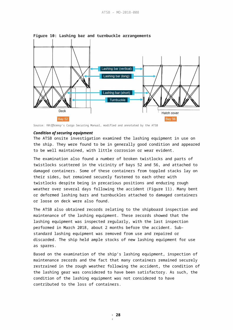
› 29 ‹
ATSB – MO-2018-008
forces into the lashing system and containers are reduced when the stack is vertically stratified, with the heaviest containers located in the lower tiers
container lashing calculation software is used to calculate and verify that the container securing arrangements comply with the applicable strength requirements and acceptance criteria
the container weight limits given by the computer lashing program are to be strictly followed in practice.
YM Efficiency’s loading computer systemYM Efficiency’s loading computer system—‘TSB Supercargo’—was designed by Total Soft Bank. The system allowed the user to perform a range of functions and checks associated with the safe stowage, loading and carriage of containers.
In particular, the system’s lashing calculation program allowed the user to calculate, for a given container stowage arrangement, the resultant forces acting upon containers and the securing system based on the class-defined assumptions for the worst combination of dynamic and static forces expected at sea. The use of a loading computer system allowed for increased flexibility in container stowage and carriage. Stowage arrangements could be assessed and accepted even if they deviated from the mass-distribution arrangement in the manual, provided the lashing calculation program was used to check that calculated forces were within allowable limits. This also made it possible for a heavy container to be accepted for loading over a light container, provided the calculated forces were found to be within allowable limits.
Operation of the TSB SupercargoChecks of the proposed container stowage arrangements using the TSB Supercargo required an electronic file containing the stowage plan to be loaded into the system and then checked for compliance against various requirements such as the design stack weight check and lashing calculation check. In addition, the system could also be used to check the stowage plan for compliance with the International Maritime Dangerous Goods Code (IMDG Code)43 requirements.
Design stack weight checkThe ship’s design stack weight was a maximum limiting value based solely upon the strength of the ship’s deck, fittings and hatch covers. This value was different from the maximum stack weight in the mass-distribution arrangement, which considered the effect of container weights on the calculated forces acting on containers and lashings.
The maximum design stack weight was 80 t for a stack of 20-foot containers and 110 t for a stack of 40-foot containers.
TSB Supercargo could be used to check the stowage arrangement against the ship’s design stack weight to ensure that the ship’s deck and hatch structures were not overloaded. If a container stack exceeded the design stack weight, the program indicated this by displaying the exceedance in red above the relevant stack. YM Efficiency’s chief mate stated that this check was performed with no exceedances detected. ATSB analysis confirmed that there were no design stack weight exceedances.
IMDG compliance checkThe carriage of dangerous goods by sea has to be conducted in accordance with the IMDG Code. The Code classifies dangerous goods (DG) into nine classes. A key aspect of safe cargo stowage related to the carriage of dangerous goods involved the segregation of containers carrying dangerous cargo from other containers carrying incompatible classes of dangerous cargo. Containers carrying certain classes of dangerous cargo also had to be segregated from refrigerated cargo containers. A check to ensure that this was carried out was marked as completed in the chief mate’s container stowage checklist for the port call at Kaohsiung.
43 The International Maritime Dangerous Goods Code (IMDG Code) is a uniform, international code for the safe transport of dangerous goods by sea. The Code covers aspects such as the marking, packaging, stowage and segregation of dangerous goods during transport.

› 30 ‹
ATSB – MO-2018-008
Checks of YM Efficiency’s container stowage arrangement after the occurrence, using the ship’s loading computer system, identified 10 unresolved IMDG segregation conflicts. These conflicts involved DG containers being stowed in proximity to other non-compatible DG containers or refrigerated containers without the separation required by the Code.
Lashing forces calculation checkThe lashing forces calculation check assessed the container stowage arrangement against the maximum values for lashing forces described in the CSM. Setup for the check involved selecting appropriate values for the strength and flexibility parameters of the lashing equipment, the lashing pattern in use, limits of forces and other parameters. Alternatively, default values based on generic DNV GL container stowage and securing rules44 and, minimum acceptable equipment SWL and MBL values from the ship’s CSM could be used. DNV GL default values for the allowable limits of calculated lashing forces were largely identical to those defined by ABS in YM Efficiency’s CSM. The program calculated the maximum forces expected to be generated on containers and securing systems based on the assumed worst combination of static and dynamic forces as defined in the CSM.
TSB Supercargo did not specifically provide an indication if container stacks exceeded the stack weights provided in the container mass-distribution arrangement (which could be less than the maximum design stack weight). Nor did it alert the user if individual container weights exceeded the maximum weights for individual slots or if the maximum number of tiers were exceeded. Instead, the program calculated the effect of container weights and their distribution, on the forces acting on the containers and their securing system.
The program indicated these calculated forces either as a percentage of the maximum allowable force or as units of force (kN). In both cases, an exceedance of the maximum allowable value of the lashing force would be indicated in red, allowing the operator to readily identify the container stacks where changes needed to be made to reduce the calculated forces to acceptable values.
Analysis of the stowage arrangementAfter the accident, lashing calculation checks were performed by the ship’s manager, Yang Ming, on YM Efficiency’s container stowage arrangement as presented to the ship in Kaohsiung. The checks were performed using the same TSB Supercargo software program as was in use on board the ship. The check was performed using the program’s default values. The stowage plan, container weights and other underlying parameters, such as limits of forces, were verified by the ATSB. The outcome of the checks showed that calculated forces in a number of stacks in bays 52 and 56 exceeded allowable limits of lashing forces as indicated by the highlighted figures in red (Figure 17, see Appendix E for a larger version).
Further checks by Yang Ming at the ATSB’s request, involving minor variations to lashing force parameters, lashing equipment characteristics and vessel speed did not provide significantly different results.
44 DNV GL, 2013, Rules I - Ship Technology, Part 1 - Seagoing ships, Chapter 20 - Stowage and lashing of containers.

› 31 ‹
ATSB – MO-2018-008
Figure 17: Outcome of lashing forces calculation check (actual values)
An indicative image primarily showing the lashing forces calculation check for bays 52 and 56 with results displayed in kN. Values of lashing forces in excess of the maximum allowable forces are displayed in a red font (highlighted by the ATSB).Source: Yang Ming, modified and annotated by the ATSB
Figure 18 (and Appendix F) detail the outcome of the same lashing check expressed as a percentage of the maximum allowable forces. Calculated forces that exceeded 100 per cent of the allowable value are indicated by figures in red.
Figure 18: Outcome of lashing forces calculation check (percentage)
An indicative image primarily showing the lashing forces calculation check for bays 52 and 56 with results displayed as a percentage of the maximum allowable forces. Values of lashing forces in excess of the maximum allowable forces are displayed in a red font.Source: Yang Ming, modified by the ATSB
In addition, there were a few other instances (in bay 48 located immediately forward of the accommodation) where calculated forces exceeded allowable values. However, no containers were lost or damaged in this bay. Lashing forces in all other bays were within the allowable limits.
Lashing calculation check of bay 52A lashing calculation check of YM Efficiency’s container stowage arrangement showed that calculated forces in at least 10 locations in bay 52 exceeded the allowable limits of various forces (Figure 19).

› 32 ‹
ATSB – MO-2018-008
For example, for the container in position 520382, calculations show lifting force at 237 per cent (about 592 kN) of the allowable force of 250 kN. This indicates a lifting force in excess of the 500 kN MBL of the twistlocks. Similarly, calculated load on the container corner posts were at 147 per cent of the allowable compressive corner post load of 848 kN.
Figure 19: Bay 52 plan showing calculated force exceedances
Source: Yang Ming, modified and annotated by the ATSB
Lashing calculation check of bay 56A lashing calculation check of YM Efficiency’s container stowage arrangement showed that calculated forces in at least eight locations in bay 56 exceeded the allowable limits of various forces (Figure 20).
For example, for the container in position 560682, calculated lifting force was at 262 per cent (655 kN) of the allowable lifting force of 250 kN and in excess of the 500 kN MBL of the twistlocks. Similarly, calculated load on the container corner posts were at 152 per cent of the allowable compressive corner post load of 848 kN.
Figure 20: Bay 56 plan showing calculated force exceedances
Source: Yang Ming, modified and annotated by the ATSB
Effect of forcesSignificant exceedance of the compressive corner post load would typically be expected to manifest as a collapse of the container’s corner post/s (Figure 21). This can result in the stack becoming unstable and collapsing to either side, thereby placing forces on adjoining stacks or structures. Racking force exceedances typically manifested as a deformation or distortion of the

› 33 ‹
ATSB – MO-2018-008
container box structure. There was no safety factor applied to the maximum design corner post load (848 kN) and maximum racking force (150 kN) values for the container structure.
Figure 21: Image showing container corner post collapse
Source: ATSB
Exceedance of the lifting forces could result in excessive and potentially destructive stresses on container corner sockets, twistlocks, turnbuckles and lashing rods (Figure 22). The destructive failure of one or more twistlocks leaves the container and those above it partially or completely unsecured. This can result in the loss or uncontrolled movement of the container leading to a collapse or toppling of the stack. This can also place stresses on adjoining stacks that were not allowed for in the design of the lashing system.
It is important to note that, for the container loss to have occurred, it was not necessary for every single instance of a force exceedance to have manifested as a failure of the container or lashing device. Any one structural failure of a container and/or lashing or, a combination of such failures could have given rise to the sequence of events that resulted in the loss of containers overboard.

› 34 ‹
ATSB – MO-2018-008
Figure 22: Examples of lifting force exceedances
Source: ATSB
Conduct of the lashing forces calculation checkThe chief mate stated that he did not perform a lashing forces calculation check of the proposed container stowage plan in Kaohsiung. The master believed that he would be consulted by the chief mate if there were any difficulties or issues with the cargo plan. He also stated that he considered the chief mate to be an experienced and capable officer. The fact that he was not called upon for assistance led to the master assuming that the cargo plan had been approved without any significant unresolved issues.
Training and knowledge The chief mate and master both stated that they were unfamiliar with the set-up and use of the lashing forces calculation check using TSB Supercargo’s lashing calculation program. The unresolved IMDG segregation conflicts in the cargo plan suggested that there might also have been an inadequate understanding of other aspects of the loading computer system.
There was no evidence of training in the use of TSB Supercargo being provided to ship’s officers prior to the accident (training was provided to the chief mate and master after the accident). Junior officers were usually trained in the use of the system and its checks while on the job, by senior officers. While newly promoted chief mates were usually supervised on board by the master until confident in the conduct of the checks, YM Efficiency’s chief mate was an experienced officer with many years’ experience as a chief mate on container ships.
Cargo-planning processYM Efficiency berthed at Kaohsiung at 1448 in the afternoon of 31 May and sailed shortly before midnight that same day. During this approximately 9-hour port stay, the ship loaded 881 containers and discharged two containers. This time also included the checks and approval of the proposed cargo plan and checking of container lashings by the ship’s crew.

› 35 ‹
ATSB – MO-2018-008
Container ship operations generally involve certain key phases involving responsible individuals both ashore and on board the ship. Yang Ming’s container planning and operations process could be divided into activities during the following three location-based phases:
stowage planning centre port container terminal shipboard.
Stowage planning centreThe Yang Ming stowage planning centre is located in Keelung, Taiwan. The centre was staffed with cargo planners who were trained and employed by Yang Ming. Cargo planners were primarily ex-seafarers or graduates of maritime colleges (with little seagoing experience). The SMS required that cargo stowage, stability and draught calculations be performed ashore in advance of cargo operations on board the ship.
The loading port agency accepted container bookings from shippers and forwarded the forecast cargo details to the stowage planning centre (identified as the ‘centre planning office’ in the shipboard SMS). These planners organised the ship’s final container bookings forecast and prepared a draft stowage plan with loading instructions. The preparation of the draft stowage plan took into account a number of factors, including the cargo to be unloaded, the ship’s expected stability condition, its schedule and order of discharge ports, forecast container bookings and special cargo requirements. This stowage plan did not include final container weights for the containers expected to be loaded nor could it account for any containers that arrived at the terminal late or that did not arrive at all. The stowage plan and associated loading instructions were then sent to the container terminal (in this case, Kaohsiung).
The shore planners used a version of computer automated stowage planning software (commonly known as ‘CASP’) that did not include the lashing forces calculation program. Hence, there was no lashing forces calculation check of the proposed container stowage plan performed at the shore planning stage. As a result, a stowage arrangement with significant weight and distribution irregularities was submitted to the terminal for YM Efficiency’s cargo operations.
As part of the investigation, the ATSB reviewed the current practices of other major container ship operators. This research identified that planning processes have the means of incorporating lashing forces calculation checks into the shore planning process. Further, a number of those operators considered the conduct of these checks ashore as an integral part of the shore planning process. They advised that consideration of lashing forces were taken into account from the very outset in order to reduce the risk of an unsafe stowage plan being presented to the ship.
Port container terminalAs is common in the marine industry, the planners at the Kaohsiung container terminal were employed by the terminal, not by Yang Ming. Their responsibilities were largely restricted to the operational aspects of the ship’s port call including the discharge and loading of containers. The terminal planner finalised the stowage plan by entering the verified weights of containers as they arrived at the load port. The plan was also adjusted for any planned containers that were late or that did not arrive at the load port. The loading and unloading sequence for the ship’s port call was then planned, taking into account Yang Ming’s loading instructions.
Yang Ming stated that a (design) stack weight check was performed before the plan was presented to the ship but not a lashing calculation check. The stowage planning software used at the terminal did not include the lashing forces calculation program and the conduct of a lashing forces check was not part of the terminal planning process.
The stowage plan was then presented to the ship as an electronic file for final checking and approval.

› 36 ‹
ATSB – MO-2018-008
ShipboardThe electronic file containing the proposed stowage plan was presented to the ship upon arrival in port or shortly before. The ship’s responsible officer (the chief mate) was then expected to check the plan against a number of specified criteria such as IMDG compatibility, acceptability of container weight and distribution and stack weight checks, before approving the plan for actioning. Any identified irregularities were to be rectified or were to be referred ashore for assistance.
Yang Ming stated that the electronic file containing the planned stowage arrangement and container details was provided to YM Efficiency for approval by email about 2 hours prior to its arrival at Kaohsiung. The proposed plan was also provided to the chief mate by the terminal planner after the ship berthed.
The ship’s passage from the previous port, Shekou, was estimated to have taken about 18 hours with the ship embarking the harbour pilot for Kaohsiung at about 1400 on 13 May. The chief mate, who was the ship’s responsible cargo officer, also performed the duties of the OOW on the 0400-0800 and 1600-2000 bridge watches. Records of hours of rest for 13 May show that the chief mate was resting between 1200 and 1400 before attending to the port call at Kaohsiung. This meant that there was limited opportunity for him to check the proposed cargo plan received by email before the ship berthed.
The electronic file containing the proposed stowage plan was received from the terminal planner at about 1515 (about 30 minutes after the ship berthed). The SMS required the chief mate to check the proposed plan using the loading computer system and, if there was any irregularity, that the chief mate immediately request a rectification. A rectification could potentially involve re-positioning or cancellation of the containers involved. These checks and any associated amendments had to be conducted after the ship berthed with cargo operations imminent. While the SMS expected the ship’s officers to seek shore assistance if necessary, shore planners did not have the software capability to perform lashing force calculations. This meant that the punctual start, and the efficient conduct, of cargo operations depended on the chief mate’s ability to check, rectify and verify the proposed cargo plan in a timely and effective manner.
Container stowage checklistA summary of the checks required under the ship’s SMS was provided in the form of a container stowage checklist (Appendix G). The completed checklist for the ship’s call at Kaohsiung on 13 May noted that, among others, the following checks of the proposed stowage arrangement were performed by the chief mate:
dangerous cargo list received and verified dangerous cargo stowage in compliance with the IMDG Code, local requirements and Yang
Ming policy calculated GM, longitudinal strength and bridge visibility in compliance with safety condition each stack weight below deck strength limitation (design stack weight) vertical weight distribution in compliance with lashing system recommendation.The checklist also recorded the ship’s maximum shear forces (44 per cent), maximum bending moments (69 per cent) and GM (1.09 m).
The chief mate recalled checking that the design stack weight was not exceeded and that planned container locations were suitable for the containers to be loaded including for refrigerated containers and containers carrying dangerous goods. The chief mate also checked that the ship’s stability parameters met the IMO criteria and that bending moments and shear forces were within acceptable limits. However, a check of calculated lashing forces, which would have identified the vertical weight distribution irregularities in the proposed stowage arrangement, was not performed.
The chief mate subsequently approved the stowage and loading plan without requesting any changes. The checklist noted that the final, verified bay plan was received at about 1545 and that cargo operations commenced at 1600.

› 37 ‹
ATSB – MO-2018-008
The absence of a lashing forces check during the planning process ashore meant that an inherently unsafe container stowage arrangement was presented to the ship for approval. The omission of the shipboard lashing forces check removed the last opportunity to identify the safety implications of the proposed stowage arrangement. Consequently, the ship was loaded in accordance with the unsafe stowage arrangement.
Rectification of identified issuesOn board YM Efficiency, rectification of issues identified during the shipboard check depended on action by the responsible ship’s officers.
Rectification of calculated lashing force exceedances generally involved relocation of containers such that calculated forces were reduced to acceptable levels. This might involve the redistribution of container (weights) within the stack, within the bay or elsewhere on the ship. If the redistribution of containers failed to address the issue, the implementation of additional mitigating measures might be considered, such as reducing the ship’s GM through ballasting. As a last resort, a container may be cancelled for carriage.
The redistribution of containers would essentially need to be done by the chief mate on a ‘trial and error’ basis until the check showed that calculated forces fell within allowable limits. TSB Supercargo did not have the capability to offer solutions to identified lashing force calculation exceedances. However, an effective starting point would possibly have involved repositioning containers to eliminate situations where significantly heavier containers were loaded over lighter ones.
In bay 52, this would have been relatively straightforward, given that the bay was empty on arrival in Kaohsiung. The order of loading containers could have been changed to ensure that heavier containers were loaded at the bottom, with containers designated for loading in the bay swapped with other bays if necessary.
However, in bay 56, the first five tiers of containers had been loaded in Shanghai and were already on board on arrival at Kaohsiung (Appendix H). The stowage plan proposed the loading of three additional tiers above the Shanghai cargo. With a few exceptions, almost all the Kaohsiung containers were heavier than those from Shanghai in the tiers immediately below them. The rectification of this situation would have involved either relocating the heavy containers to a different bay or the discharge of the relevant Shanghai containers, loading of the heavier Kaohsiung containers and then reloading the Shanghai containers on top. The latter method, involved the undesirable ‘double-handling’ of containers.
Rectification of irregularities related to the weight and distribution of containers in a proposed stow would almost inevitably involve the redistribution of containers within or across the ship’s bays. The redistribution of cargo would also potentially introduce additional conflicts related to lashing forces, stability, IMO visibility rules, IMDG segregation rules and port discharge schedules. These conflicts would have to be resolved and the plan re-checked before execution.
Depending on the planned sequence of operations, this rectification may be able to take place while other cargo operations get underway. However, as operations progress, there would be increasingly limited options available to the chief mate that would allow the redistribution of containers without over-stowing cargo and affecting work already completed or underway. Further, additional shore gantry crane ‘moves’ associated with the redistribution of cargo would incur additional costs.
The alternative was to delay or suspend cargo operations while modifications were made to the plan and those changes re-checked and approved. Delays to a ship’s operations in port would have knock-on effects on sailing and berthing schedules, waiting times, container storage and warehousing, and potentially introduce delays to the container transport chain ashore. In an environment where speed of operations is of critical concern, any delays would likely attract considerable commercial penalties.

› 38 ‹
ATSB – MO-2018-008
In summary, the costs, disruption and delays to operations associated with making substantial modifications to the cargo plan at the last minute places unrealistic expectations on the ship’s officers. Under such circumstances, it is unlikely that the chief mate would have the necessary influence to delay or suspend operations while pursuing increasingly limited options for the modification of the cargo plan.
Incident reporting and communicationsReporting procedures in the YM Efficiency’s SMS required the master to notify the company’s marine department in the event of an incident. The master informed the company of this incident via satellite telephone at about 0130 on 1 June, about 1 hour after the containers were lost overboard. The procedures also instructed the master to comply with all relevant international requirements in relation to the incident.
AMSA reporting requirementsAustralian legislation requires that all foreign and Australian vessels involved in a marine incident in Australian waters report the incident to the Australian Maritime Safety Authority (AMSA). The responsibility to report an incident, including loss of a cargo from a ship, is that of its owner and master.45 The reporting involves a two-step process, which consisted of an incident alert and a subsequent incident report with more detail.
In the event of an incident in Australian waters, an incident alert needs to be submitted as soon as ‘reasonably practicable’. Marine Order 146 clarified this by requiring the incident alert to be submitted within 4 hours of the incident. The incident alert is to be submitted by completing an incident alert form47 online or by downloading the form, completing it and emailing it to AMSA. Following the submission of the incident alert, vessels are required to submit a more detailed incident report48 within 72 hours.
YM Efficiency was in coastal waters, about 14 miles from land when the loss of containers occurred. The main engine shutdown and prevailing weather meant that the disabled ship, as well as the lost containers, subsequently drifted into territorial waters. YM Efficiency’s incident alert, in the form of an AMSA form 18 sent by email using satellite services, was not submitted until about 1153 on 1 June, nearly 12 hours after the incident. The incident alert was submitted to the ship’s local agent who notified port authorities. Subsequently, AMSA’s Joint Rescue Coordination Centre and state authorities (Roads and Maritime Services) were notified of the incident.
By 1330, the Joint Rescue Coordination Centre had begun deploying air surveillance assets. Shortly after, AMSA began drift modelling49 to predict where the containers were likely to be washed ashore. Maritime safety information broadcasts to warn shipping of the lost containers were also initiated by about 1500. By the late afternoon, there were reports of two containers drifting off Port Stephens. The State authorities implemented state spill contingency plans and liaised with local fire and rescue services to respond to reports of containers that washed ashore.
In the days following the accident, coast radio stations including Newcastle VTIC and Marine Rescue NSW bases assisted with the dissemination of maritime safety information concerning the lost containers.
45 Sections 185 and 186 of the Navigation Act 2012 (Cth).46 Marine orders are legal instruments made by AMSA pursuant to powers under Commonwealth legislation. They are
also described as regulatory instruments or legislative regulations.47 Incident alert form 18, available at www.amsa.gov.au48 Incident alert form 19, available at www.amsa.gov.au49 Drift modelling was facilitated by the deployment of self-locating datum marker buoys designed to measure surface
ocean currents.

› 39 ‹
ATSB – MO-2018-008
Safety communicationsSafety communications are those communications used to convey important navigational or meteorological warnings. Safety communications have priority over all communications except distress and urgency communications.
Safety communications can be transmitted either using terrestrial systems such as very high frequency radio (VHF) or using satellite-based systems. In a terrestrial system, safety communications consist of a safety announcement using digital selective calling (DSC) followed by a safety call and safety message using radiotelephony or other means.
The safety call comprises the initial voice or text procedure, including the safety signal, prior to the transmission the safety message. The safety message indicates that the calling station has an important navigational or meteorological warning to transmit. International and Australian regulations placed a responsibility on the ship’s master to inform all vessels in the vicinity of any serious danger to navigation by transmitting a safety signal and message.50
When a safety message is transmitted via radiotelephony, the preceding safety signal comprises the word ‘SECURITE’ spoken three times. This is followed by the identity of stations to whom the message is addressed and the transmitting station’s identity. Safety messages from ships to other stations in the vicinity are usually addressed to all stations.
YM Efficiency’s safety message transmissionsAt about 0229 and 0231, the YM Efficiency’s second mate (the OOW) broadcast two radiotelephony calls on VHF channel 16. These calls were not preceded by a digital selective calling safety announcement or by a safety call with the spoken word ‘SECURITE’. Further, the ship’s broadcasts did not follow the form required of emergency radiotelephony voice procedures. The two radiotelephony calls, however, were broadcast addressed to all stations, stated the ship’s name, that containers were lost overboard and the position where the containers were lost.
As the calls were broadcast on VHF radio, they had a limited range (generally, within line of sight). Stations within range of the broadcast and capable of receiving the message would have included other ships in the vicinity (there were several), Newcastle VTIC, volunteer marine rescue bases, and any other stations monitoring channel 16. Of these, some stations had a responsibility to listen for distress and emergency communications.
National Coast Radio NetworkAs part of its SOLAS obligations, Australia provides a satellite and high frequency (HF) radio communications service that forms part of the global maritime distress safety system (GMDSS).51 The Australian GMDSS-network does not provide voice watchkeeping on the distress radiotelephony frequencies.
The National Coast Radio Network was established in July 2002 to replace the Commonwealth Coastal Radio Network. Each jurisdiction monitored the relevant VHF and HF distress and calling frequencies and broadcast relevant navigation warnings and maritime safety information.
In NSW, marine radio services were provided by Kordia (a specialist telecommunications company), the port corporations of three NSW ports52 and Marine Rescue NSW.
Newcastle VTICNewcastle Port Corporation was one of the three port corporations that formed part of the National Coast Radio Network. The primary role of Newcastle VTIC was the planning, booking and coordination of ship movements for the port of Newcastle. However, as part of the National Coast Radio Network, Newcastle VTIC provided part of the VHF component of the network and
50 Section 187 of the Navigation Act 2012 (Cth).51 Australia holds sea area A3.52 The port corporations of Sydney, Newcastle and Port Kembla.

› 40 ‹
ATSB – MO-2018-008
monitored VHF channel 16 for distress and emergency communications at all times (primarily from domestic and recreational vessels rather than from seagoing merchant ships).
A review of Newcastle VTIC’s archived audio data for 1 June confirmed that YM Efficiency’s broadcasts on channel 16 were recorded. However, there was no evidence to indicate that the VTIC operator/s heard, documented, acknowledged or took any action in response to the broadcasts. The earliest awareness of the accident was shortly after 0700, when reports of a container loss from YM Efficiency were heard on local public radio broadcasts by the Australian Broadcasting Corporation (ABC).
Marine Rescue NSWVolunteer rescue organisations are located throughout Australia with a focus primarily on promoting safety and carrying out local rescues. As such, volunteer marine rescue radio operators normally only responded to calls directly addressed to them. Nevertheless, in NSW, part of the State’s marine radio services were provided by volunteer marine rescue bases.
Archived electronic audio recordings obtained from the Port Stephens marine rescue base confirmed that YM Efficiency’s VHF broadcasts were recorded there. However, as with Newcastle VTIC, there were no documented log entries either in the Port Stephens base log or in the Marine Rescue NSW state-wide log, and there was no awareness of the accident. The earliest that Marine Rescue NSW personnel gained an awareness of the container loss was at about 0647, when contacted by the ABC.
Similar occurrencesOver the past few decades, flag administrations and agencies with a responsibility to investigate safety occurrences have investigated several container loss and container damage events. Some common recurring, contributory factors identified in these investigations include stack weight exceedances, excessive compression and racking forces, and shortcomings in the shore planning process. Another factor that was common to a number of these investigations was the difficulty encountered in conclusively determining an external cause for the ship’s motion or movement that contributed to the incident.
Svendborg MaerskOn 14 February 2014, the 8,160 TEU, 347 m Denmark-registered container ship Svendborg Maersk lost 517 containers overboard with a further 250 containers damaged. The incident occurred when the ship suddenly rolled to extreme angles on two occasions while the ship was on passage in the Atlantic Ocean off Ushant, France.
Denmark’s Maritime Accident Investigation Board investigation report—Svendborg Maersk – Heavy weather damage on 14 February 2014, identified that, on two separate occasions, Svendborg Maersk encountered extremities in an adverse weather situation, causing heavy rolling. The investigation was unable to establish whether the extreme rolling motions of the ship were caused by parametric resonance or single waves that were different from the predominant wave pattern.
Pacific AdventurerOn 11 March 2009, the 1,123 TEU, 185 m Hong Kong-registered multi-purpose container ship Pacific Adventurer lost 31 containers overboard off Cape Moreton, Queensland, Australia. The containers were lost when the ship rolled violently while on passage to Brisbane. At the time, the ship was being subjected to the effects of tropical cyclone Hamish. Two of the ship’s fuel oil tanks were holed as the containers went overboard, resulting in 270 t of fuel oil leaking into the sea, polluting 38 miles of the coastline.
The ATSB transport safety investigation report MO-2009-002 identified that Pacific Adventurer probably experienced synchronous or resonant rolling in the time leading up to the loss of

› 41 ‹
ATSB – MO-2018-008
containers, brought about by the ship’s natural roll period matching the encounter period of the waves.
AnnabellaIn February 2007, the 868 TEU, 134.4 m-long, United Kingdom (UK)-registered container ship Annabella sustained a collapse of cargo containers stowed in a cargo hold. The incident occurred in the Baltic Sea in adverse weather, while the ship was on passage from Antwerp, Belgium to Helsinki, Finland. Three of the collapsed containers contained hazardous cargo and the ship was redirected to port of Kotka where emergency services and specialist contractors attended and safely unloaded the hazardous containers.
The UK’s Marine Accident Investigation Branch (MAIB) investigation Report No. 21/2007 concluded that the collapse of cargo containers occurred as a result of compression and racking forces acting on the lower containers of the stack. Maximum allowable stack weights had been exceeded and lashing bars had not been applied to the containers as required. Class approval of the loading computer system did not include the container and lashing modules, which contributed to a programming error not being detected. In addition, the report identified that the master did not report the accident to the coastal state authorities as soon as possible, potentially delaying timely and effective support from shore authorities.
The MAIB also found that the pace of modern container operations is such that it is very difficult for ship’s staff to maintain control of the loading plan.
P&O Nedlloyd GenoaOn 27 January 2006, the 2,902 TEU, 210.1 m-long, UK-registered container ship P&O Nedlloyd Genoa lost 27 containers overboard in the Atlantic Ocean while on passage from Le Havre, France to Newark, United States. The incident occurred when the ship was struck by a steep-sided swell wave during a series of large rolls initiated by large swell waves. In addition to the loss of containers overboard, the ship also sustained a collapse of 28 containers.
The UK’s MAIB investigated the incident and published Report No. 20/2006. The investigation could not determine the cause of the accident with any certainty. Sea conditions did not appear to have been steady enough to induce parametric rolling and the ship’s natural roll period appeared to have been just outside the limits for parametric rolling.
The report concluded that the stowage plan in the affected bay exceeded the maximum stack weight limit in the outboard row and disregarded the principle of ‘no heavy over lights’ loading. Errors in the stowage plan were not identified by the company’s planning staff, the terminal or the ship’s chief mate.
Dutch NavigatorIn April 2001, the 99 m-long, Netherlands-registered general cargo ship Dutch Navigator encountered poor weather that resulted in a shift of nine cargo container units in the foremost bay of cargo hold. The incident occurred while on passage from Bilbao, Spain to Avonmouth, UK. Two of the nine units were tank containers containing incompatible dangerous goods, with one of these tank containers significantly damaged with a leak.
The UK’s MAIB investigated the incident and published Report No. 37/2002. The investigation concluded that container stack masses in bay 01 of the hold were substantially in excess of the recommendations of the ship’s CSM and that the stowage of tank containers in the hold did not comply with the IMDG Code. Calculated racking loads on the container frames in the lower tier of bay 01 were substantially in excess of design limits and were considered to be a major factor in the failure of the stow.

› 42 ‹
ATSB – MO-2018-008
Safety analysisAt about 0035 on 1 June 2018, YM Efficiency was en route to Sydney, steaming at about 3–4 knots into strong gale force winds and very rough seas off Newcastle when it suddenly rolled heavily (nearly 30° to either side). As a result, a number of container stacks on deck collapsed or toppled with 81 containers lost overboard and 62 others damaged. Soon after the container stacks began collapsing, the ship’s main engine shut down.
As the ship drifted without propulsion, no further containers were lost overboard. After some delays, the main engine was restarted and the passage resumed. The ship arrived off Sydney later that day but no berth in the port was made available. Consequently, the ship remained at sea in persisting bad weather until it berthed at the Port Botany container terminal in Sydney on 6 June. Fortuitously, none of the damaged containers on board were lost during that extended period. Meanwhile, debris from the lost containers that had not sunk continued washing up ashore.
Early in the ATSB investigation, it became evident that the sudden, heavy rolling directly resulted in the collapse of the container stacks, and the loss of propulsion immediately afterwards. Therefore, all potential causes for the rolling were explored. While the possibility of an abnormal wave could not be ruled out, there was insufficient evidence to conclude that this was the case. Similarly, the rolling could not be attributed to parametric rolling because there was insufficient evidence to definitively conclude that the conditions conducive to allow this behaviour were present. YM Efficiency had not been in beam seas, the ship’s calculated roll period was outside the range expected for synchronous rolling and other relevant stability parameters were not abnormal or unusual. Therefore, no definitive reason/s for the sudden rolling could be established.
However, the investigation identified a number of contributing and other safety factors under the following broad areas:
container stowage and securing cargo planning and checking navigation in adverse weather incident reporting and communications.
Container stowage and securingAs with most container ships, YM Efficiency had a Cargo Securing Manual (CSM) and a loading computer system to assist its master and crew with the safe carriage of containers. These tools provided all that was necessary from a mandatory and practical standpoint to plan and safely carry cargo. Together, they were a primary risk control – a control that was easier to manage, and much more predictable, than the weather.
Cargo Securing ManualThe CSM mandates how containers are stowed and secured to ensure that forces acting on the containers and their lashings do not exceed defined safe limits for carriage. A number of factors influence these forces, including container weight and location, stack height, and stability characteristics, such as metacentric height (GM) and roll period. The weight of containers and their vertical distribution in a stack are critical factors. The CSM provided mass-distribution arrangements to avoid stowage arrangements exceeding safe force limits.
YM Efficiency’s stowage arrangements in bays 52 and 56 (to which the collapsing container stacks were confined) did not conform to the applicable mass-distribution requirements. There were significant deviations, particularly with respect to container weights and stack weights, tier heights, and other inconsistencies, as summarised below:
the stowage arrangement exceeded the 7-tier limit specified (loaded to a height of 8 tiers)

› 43 ‹
ATSB – MO-2018-008
many stacks of 40-foot ‘high cube’ containers exceeded the maximum stack weights specified many container weights exceeded the weights specified for individual slots there were many instances of heavy containers above lighter ones, contrary to principles of
vertical distribution.
The type and extent of these deviations introduced a high level of risk, which was realised when the ship rolled heavily. While the stowage arrangements were not planned by direct reference to the mass-distribution arrangements, the exceedances of weights and tier heights directly influenced the lashing forces acting on the container stacks and lashings.
In practice, lashing forces in the proposed stowage arrangements were to be calculated and assessed for compliance with the requirements of the CSM using the loading computer system. Use of the loading computer system offered a flexible and efficient way to ensure compliance with the CSM.
Loading computer systemYM Efficiency’s loading computer system included a lashing calculation program that allowed for a direct check of the forces acting on containers and lashings. Analysis of the stowage arrangement (based on default values similar to those in YM Efficiency’s CSM) showed that calculated forces exceeded maximum allowable values at several locations in bays 52 and 56. Specifically, calculated values for lifting force, compressive force on corner post loads and racking forces exceeded allowable limits as follows:
In bay 52, there were;
10 instances of lifting force exceeding the maximum (including four exceeding 200 per cent) four instances of corner post load exceeding the maximum (including two exceeding 140 per
cent) two instances of racking forces exceeding the maximum.
In bay 56, there were;
eight instances of lifting force exceeding the maximum (including four exceeding 200 per cent) four instances of corner post load exceeding the maximum (including two exceeding 150 per
cent) two instances of racking forces exceeding the maximum.
The lashing force exceedances determined by the ship’s lashing calculation program were a direct result of the weights and distribution of containers in the bays. By contrast, calculated lashing forces in other bays were generally compliant with the CSM (with minor exceptions in bay 48) and almost no container damage or loss occurred there.
Resultant forces were calculated in the CSM for the most severe combination of forces expected, based on certain theoretical extreme values for aspects of the ship’s motion such as roll, pitch and heave. This meant that when the ship encountered conditions that approached or exceeded those theoretical values, it became increasingly likely that the calculated resultant forces would be physically realised. For example, the angle to which the ship rolled (nearly 30°) exceeded the theoretical angle of roll (25.1°) used in the calculations. Therefore, it was almost certain that forces generated during the rolling approached or exceeded the forces determined by the lashing calculation program.
The heavy rolling gave rise to accelerations, which in turn generated excessive forces in the container stacks. This placed stresses and loads on containers and lashings that were in excess of the strengths and minimum breaking loads for which they were designed, resulting in their structural failure. It was not necessary for every identified calculated force exceedance to be realised - any single exceedance or combination of exceedances could have initiated the failure

› 44 ‹
ATSB – MO-2018-008
sequence. The ensuing collapse and toppling of container stacks led directly to the loss of containers overboard.
Use of the loading computer systemThe lashing forces calculation check was an important risk control measure to ensure that proposed container stowage arrangements complied with the requirements of the CSM. Yang Ming’s cargo planning process ashore did not incorporate a lashing forces check (see the section titled Cargo planning). Therefore, the shipboard check was the final, and only, opportunity to check the proposed stowage plan before it was implemented on the ship.
Yang Ming procedures required that proposed container stowage plans be checked on board the ship for safety and compliance with the CSM. Any irregularities identified in the stowage arrangement were to be rectified to the master’s satisfaction before the ship sailed. In practice, proposed container stowage plans should have been checked using the loading computer system and its built-in lashing calculation program.
The checklist for cargo operations at Kaohsiung indicated that a number of checks required by the ship’s procedures were performed and found satisfactory. However, YM Efficiency’s proposed container stowage plan was not checked using the lashing calculation program at Kaohsiung.
The checklist also noted that the proposed stowage plan was checked for compliance with the IMDG Code. However, the ten unresolved dangerous goods segregation conflicts identified during the investigation indicated that some checks might have been omitted or incorrectly performed.
YM Efficiency’s chief mate and master stated that they were not familiar with the set-up or use of the lashing calculation program. Evidence of other omitted or improperly performed checks suggested that this might have extended to broader aspects of the loading computer system as well. The lashing calculation program formed part of the functionality of the loading computer system (although the carriage of a loading computer system was not a requirement for the ship). The safe stowage and loading of the ship depended on the responsible officers being able to effectively operate the system, run the required checks, interpret the outcome of those checks and take the necessary action. Apart from on-the-job training and mentoring, there was no evidence to indicate that the officers had been trained in the use of the loading computer system or the lashing calculation program.
In summary, the ship’s master and chief mate did not check the proposed container stowage plan using the lashing calculation program because they probably did not have an adequate understanding of the system and its checks. This meant that a stowage arrangement with significant weight and distribution irregularities was approved for execution. When eventually subject to the sudden, heavy rolling, these irregularities gave rise to excessive forces, which culminated in the loss of containers overboard.
Cargo planning and checkingThe cargo planning process ashore offered a realistic and ideal opportunity to ensure that proposed container stowage plans complied with YM Efficiency’s CSM. However, the organisation and structure of Yang Ming’s shore operations did not include certain important safety checks. In particular, the lashing forces check was not part of any stage of the shore planning process. According to Yang Ming, it was impossible to perform the lashing forces check ashore as they could not account for container weights, containers that arrived late or that did not arrive at the terminal. Further, the version of computer automated stowage planning software used by the shore planners did not have the software required to perform these checks.
However, current industry practice indicates that the importance of conducting CSM-related checks at an early stage is well understood and the ability to perform these checks ashore during the shore planning stage exists. In fact, integration of the lashing forces checks into the shore planning process is standard practice for a number of major container ship managers.

› 45 ‹
ATSB – MO-2018-008
The absence of the lashing forces calculation check in Yang Ming’s shore planning process meant that weight and distribution irregularities in the proposed stowage plan were not identified during that stage of the planning. Consequently, an inherently unsafe stowage arrangement was presented to YM Efficiency, and compliance with the CSM requirements relied entirely on shipboard checks of the stowage arrangement at an unnecessarily late stage. While the ship’s loading computer system had the software to perform the lashing forces calculation and other checks, such as compliance with the IMDG Code, its master and crew faced other limitations.
Shipboard checks in practice occur at a late stage in the planning process when the ship is berthed with cargo operations imminent. Loading and discharge operations at container terminals are expected to be conducted quickly, efficiently and with minimum disruption to the planned sequence. The identification of multiple, serious irregularities in a proposed stowage plan would require the suspension or delay of cargo operations until the deficiencies are rectified. These delays will almost certainly have flow-on effects to the ship’s schedule, berthing schedules of other ships and port operations, which all incur a commercial cost. Such practical considerations place unrealistic expectations on ship’s officers in terms of identifying and resolving irregularities in the stowage plan, at the last minute, without unduly affecting cargo operations.
These impediments, together with a lack of loading system knowledge detailed previously, affected the ability of YM Efficiency’s master and chief mate to perform the necessary checks, interpret their outcome, understand the implications and then decide on appropriate action to address the matter.
Therefore, while shipboard checks are a necessary step in cargo planning and stowage and serve to assure the master that the proposed plan is safe and compliant, they should not be the only checks as was the case with Yang Ming’s cargo planning process. In YM Efficiency’s case, this resulted in the chief mate approving the non-compliant and unsafe proposed container stowage plan without properly checking it.
Navigation in adverse weatherA ship that is stopped generally tends to lie beam-on to the wind and seas. In a rough sea, the ship is likely to roll and, depending on the severity of the weather and the ship’s stability, may roll heavily. This can impose stresses on cargo and ship’s structures resulting in damage. The shifting of cargo can also lead to a sudden adverse change in the ship’s stability with the potential for capsizing. Drifting beam-on in rough seas also leaves the ship vulnerable to synchronous rolling.
On the afternoon of 31 May, YM Efficiency’s master decided to drift without propulsion in increasingly adverse weather conditions. The ship was subject to the effects of gale force winds between force 8 (between 34 and 40 knots) and force 9 winds (between 41 and 47 knots), 6 m seas and a 5 m swell. Analysis showed that YM Efficiency generally settled beam-on to the prevailing weather when drifting.
After the loss of containers, the ship was disabled as its main engine had shut down. In these circumstances, it was unavoidable that the ship would drift in the prevailing weather. The loss of propulsion and disablement of the ship, especially in adverse weather, is generally considered a serious situation with potential for grave danger. However, once the main engine was returned to service at about 0200, no attempt was made to start the engine to restore propulsion and regain control of the ship. The master decided to continue drifting until 0252 when the main engine was started and passage resumed, probably prompted by advice of the requirement for ships to remain 10 miles offshore.
The decision to drift on 31 May left the ship open to the possibility of synchronous rolling. Heavy rolling on a container ship can impose severe compression, racking and lifting forces. This can loosen lashings and place stresses on containers, weakening components of the system. After the accident, with collapsed stacks and loose containers on deck, it was even more imperative that control of the ship was regained to avoid any further damage and container loss.
› 46 ‹
ATSB – MO-2018-008
The initial decision to drift in adverse weather by the master was in response to a delay in the ship’s required time off arrival at Sydney. He assessed that the ship’s GM afforded adequate stability and recalled that the ship’s motion while drifting during the afternoon was comfortable with little pitching or rolling. After the accident, the master once again described conditions on board as being comfortable with little need for concern. The second mate’s recollections concurred with the master’s account.
There was insufficient evidence to establish if the decision to drift on 31 May contributed to the loss of containers overboard. There was also no evidence that the decision to continue drifting after the main engine was returned to service resulted in any adverse consequences. Nevertheless, the decision to drift in what was unarguably adverse weather increased the risk of damage to the ship and cargo, and was inconsistent with the accepted practice of good seamanship.
Incident reporting and communicationsThe loss of containers overboard from YM Efficiency was a marine incident that required reporting to the coast state authorities, in this case the Australian Maritime Safety Authority (AMSA). An incident alert was required within four hours of the incident and a subsequent incident report within 72 hours.
The requirement for an incident alert was primarily to enable authorities to mobilise resources to:
respond to the incident implement contingency plans notify relevant personnel and organisations manage risk from potential consequences.AMSA also had a responsibility to initiate promulgation of maritime safety information to those who might be affected by the lost containers.
While the master reported the incident to the ship’s managers soon after the incident, the incident alert notification to AMSA was not made until about 11 hours after the containers were lost overboard. This delayed the authorities’ response to the incident. Specifically, response actions such as drift modelling and aerial surveillance of the ship and lost containers were not initiated until more than 12 hours after the incident. Promulgation of maritime safety information for affected waters was also delayed until about 1500 (over 14 hours after the incident).
About 2 hours after the incident, YM Efficiency broadcast two messages to warn nearby vessels of the loss of containers overboard. The messages were broadcast in English, on the appropriate distress and calling frequency (VHF channel 16). The messages were addressed to all stations and contained the necessary information required to convey the details and seriousness of the incident to any listening station. However, these broadcasts did not follow the form required of emergency radiotelephony voice procedures, were not announced by a digital selective calling announcement and the calls did not include the appropriate safety message designator ‘SECURITE’.
Coast radio stations on the Australian coast received the messages broadcast by YM Efficiency. However, operators at these stations remained unaware of the incident until several hours later when they were alerted to it by a news broadcast. It is acknowledged that the primary purpose of these coast radio stations was the localised provision of services relating to port operations or the rendering of safety services to small recreational and domestic commercial vessels. In addition, the absence of appropriate message designators and the greater amount of general radio traffic off major ports may have affected the coast radio station operators’ ability to discern YM Efficiency’s message. The use of the appropriate ‘SECURITE’ message designator and digital selective calling announcements may have better alerted operators to the broadcast.

› 47 ‹
ATSB – MO-2018-008
Therefore, while the ship did make two broadcasts intended to alert radio stations in the area to the accident, they were not picked up by coast radio stations and an early opportunity to alert authorities was lost. Such early awareness would have allowed the appropriate State and Commonwealth authorities to respond to the incident in a timely manner, regardless of the delay in the master reporting the incident to AMSA via the agent.

› 48 ‹
ATSB – MO-2018-008
FindingsFrom the evidence available, the following findings are made with respect to the loss of 81 containers overboard from YM Efficiency, 16 NM east-south-east of Newcastle, New South Wales on 1 June 2018. These findings should not be read as apportioning blame or liability to any particular organisation or individual.
Safety issues, or system problems, are highlighted in bold to emphasise their importance. A safety issue is an event or condition that increases safety risk and (a) can reasonably be regarded as having the potential to adversely affect the safety of future operations, and (b) is a characteristic of an organisation or a system, rather than a characteristic of a specific individual, or characteristic of an operating environment at a specific point in time.
Contributing factors YM Efficiency suddenly rolled heavily while steaming slowly in adverse weather. That
movement generated forces which placed excessive stresses on the container stows in bays 52 and 56, resulting in the structural failure of a number of containers and components of their securing systems, and the subsequent loss of containers overboard.
The weights and distribution of containers in bays 52 and 56 were such that calculated resultant forces on containers and securing systems exceeded the allowable force limits specified in the ship’s Cargo Securing Manual.
The ship's master and chief mate did not check that the proposed container stowage plan complied with the requirements of the Cargo Securing Manual probably because neither had an adequate understanding of the loading computer system.
The ship’s manager’s (Yang Ming) cargo-planning process ashore did not ensure that the proposed container stowage plan complied with the stowage and lashing forces requirements of the ship's Cargo Securing Manual. Consequently, compliance with these requirements relied entirely on shipboard checks, made at a late stage, with limited options available for amendments without unduly impacting commercial operations. [Safety issue]
Other factors that increased risk The decision to drift in severe weather despite the main engine being available, was
inconsistent with the practice of good seamanship, and increased the risk of damage to the ship and cargo.
The ship’s radio broadcasts, intended to alert stations to the loss of containers, were transmitted on the distress and calling frequency but did not include the appropriate message designator, ‘SECURITE’ and were not preceded by a digital selective calling announcement. Coast radio stations that received the broadcasts did not acknowledge or respond to them, which meant that an early opportunity to alert Australian authorities to the incident was lost.
The loss of containers overboard was not reported to Australian authorities within the required 4 hours following the incident, significantly delaying the response to ensure the safety of navigation and the environment.
Other findings YM Efficiency's main engine shut down soon after the container loss started, and therefore
was not a contributing factor.

› 49 ‹
ATSB – MO-2018-008
Safety issues and actionsThe safety issue identified during this investigation is listed in the Findings and Safety issues and actions sections of this report. The Australian Transport Safety Bureau (ATSB) expects that all safety issues identified by the investigation should be addressed by the relevant organisation(s). In addressing those issues, the ATSB prefers to encourage relevant organisation(s) to proactively initiate safety action, rather than to issue formal safety recommendations or safety advisory notices.
Depending on the level of risk of the safety issue, the extent of corrective action taken by the relevant organisation, or the desirability of directing a broad safety message to the marine industry, the ATSB may issue safety recommendations or safety advisory notices as part of the final report.
All of the directly involved parties were provided with a draft report and invited to provide submissions. As part of that process, each organisation was asked to communicate what safety actions, if any, they had carried out or were planning to carry out in relation to each safety issue relevant to their organisation.
The initial public version of these safety issues and actions are provided separately on the ATSB website to facilitate monitoring by interested parties. Where relevant the safety issues and actions will be updated on the ATSB website as information comes to hand.
Shore planningSafety issue number: MO-2018-008-SI-01
Safety issue owner: Yang Ming Marine Transport Corporation
Operation affected: Container shipping operations
Who it affects: Ships operated by Yang Ming
Safety issue description The ship’s manager’s (Yang Ming) cargo-planning process ashore did not ensure that the proposed container stowage plan complied with the stowage and lashing forces requirements of the ship's Cargo Securing Manual. Consequently, compliance with these requirements relied entirely on shipboard checks, made at a late stage, with limited options available for amendments without unduly impacting commercial operations.
Proactive safety action
Action taken by: Yang Ming Marine Transport Corporation
Action number: MO-2018-008-NSA-005
Action date: 6 December 2018
Action type: Proactive safety action
Action status: Closed
Safety action taken: Yang Ming advised the ATSB of the following safety action taken to address the shore planning safety issue:
procedures for container stowage in the ship’s SMS were updated to include a requirement for lashing forces checks to be performed ashore, at the stowage planning centre, as well as on board
the implementation of regular training for shore planners in the principles of container stowage, loading software and cargo securing manuals

› 50 ‹
ATSB – MO-2018-008
training provided on the dangerous goods functionality of the computer automated stowage planning software used ashore
a stowage planning examination has been introduced for trainee stowage planners a review of shipboard loading computer systems was undertaken across the Yang Ming fleet
resulting in the adoption of route specific containers stowage class notations and the deployment of new, class-approved container stowage planning and lashing software on selected classes of vessels, with the same software to be used in the stowage planning centre ashore
class-approved MacGregor ‘Lashmate’ stowage calculation software installed on board YM Efficiency and sister ships.
Status of the safety issue
Issue status: Adequately addressed
Justification: The inclusion of lashing forces checks during the shore planning process is a practical means of reducing the risk of unsafe container stowage plans being presented to the ship at a late stage in the container shipping process. Familiarisation and training provided to shore planners should ensure that the outcomes of the lashing forces checks are understood and will allow effective action to be taken at an early stage. This provides assurance that container stowage plans presented to ships are as safe as practically possible.
Additional safety actionWhether or not the ATSB identifies safety issues in the course of an investigation, relevant organisations may proactively initiate safety action in order to reduce their safety risk. The ATSB has been advised of the following proactive safety action in response to this occurrence.
Yang MingYang Ming advised the ATSB of the following safety action taken following the loss of containers overboard from YM Efficiency:
a review of cargo operations procedures to ensure that verification of compliance with vertical weight distribution arrangements is performed
cargo operations procedures have been updated to reflect the requirement for ship’s officers to verify lashing forces
periodic familiarisation and shore-based training for all officers on compliance with the Cargo Securing Manual
review and amendment to navigation procedures which now require the master to report and seek advice from shore management when the ship is expected to encounter waves greater than 4 m
an emergency procedure for containers lost at sea has been included in the emergency procedures manual and includes a requirement for such incidents to be reported to the relevant parties using the standard reporting format
a directive issued to the Yang Ming fleet reminding that all deck officers need to be familiar with the on board container stowage planning and lashing software, and the cargo securing manual.
› 51 ‹
ATSB – MO-2018-008
General detailsOccurrence details
Date and time: 1 June 2018 – 0035 EST
Occurrence category: Accident
Primary occurrence type: Loss of cargo overboard
Location: 16 NM east-south-east of Newcastle, New South Wales
Latitude: 33º 01.632' S Longitude: 152º 04.332' E
Ship details – YM EfficiencyName: YM Efficiency
IMO number: 9353280
Call sign: A8OS5
Flag: Liberia
Classification society: American Bureau of Shipping
Departure: Kaohsiung, Taiwan
Destination: Sydney, Australia
Ship type: Container ship
Builder: Taiwan Shipbuilding Corporation
Year built: 2009
Owner(s): All Oceans Transportation
Manager: Yang Ming Marine Transport Corporation
Gross tonnage: 42,741
Deadweight (summer): 52,773 t
Summer draught: 12.535 m
Length overall: 268.80 m
Moulded breadth: 32.20 m
Moulded depth: 19.10 m
Main engine(s): Sulzer 7RT-flex96C
Total power: 54,460 BHP
Speed: 24.8 knots
Damage: Eighty-one containers lost overboard, 62 containers damaged, significant damage to ship’s accommodation ladder, superstructure and cargo structures

› 52 ‹
ATSB – MO-2018-008
Sources and submissionsSources of informationThe sources of information during the investigation included:
American Bureau of Shipping (ABS) Anangel Destiny Attikos Australian Maritime Safety Authority (AMSA) MacGregor Manly Hydraulics Laboratory Marine Rescue New South Wales the Port Authority of New South Wales Roads and Maritime Services (RMS) Total Soft Bank (TSB) Weather News Incorporated (WNI) the ship’s manager—Yang Ming Marine Transport Corporation YM Efficiency’s master and crew.
ReferencesGraham Danton, 1996, The theory and practice of seamanship, 11th Edition, Routledge, London.
International Maritime Organization, 2007, MSC.1/Circ.1228—Revised guidance to the Master for avoiding dangerous situations in adverse weather and sea conditions, IMO, London.
International Maritime Organization, 2014, Code of Safe Practice for Cargo Stowage and Securing, IMO, London.
International Maritime Organization, 2014, MSC.1/Circ.1353/Rev.1—Revised guidelines for the preparation of the Cargo Securing Manual, IMO, London.
International Maritime Organization, 2014, The International Convention for the Safety of Life at Sea (SOLAS) 1974 as amended, IMO, London.
Lloyd’s Register and The Standard P&I Club, A master’s guide to container securing, 2nd Edition.
National Geospatial Intelligence Agency, 2018, Sailing Directions, East Africa and the Sothern Indian Ocean (Pub. 171), NGA, Springfield.
UK P&I Club, 2004, Container lashing and stowage.
United Kingdom Hydrographic Office, 2016, The Mariner’s Handbook (NP 100), UKHO, Taunton.
SubmissionsUnder Part 4, Division 2 (Investigation Reports), Section 26 of the Transport Safety Investigation Act 2003 (the Act), the Australian Transport Safety Bureau (ATSB) may provide a draft report, on a confidential basis, to any person whom the ATSB considers appropriate. Section 26 (1) (a) of the Act allows a person receiving a draft report to make submissions to the ATSB about the draft report.
A draft of this report was provided to Yang Ming, the ship’s master, chief mate, second mate and chief engineer, AMSA, MacGregor, ABS, Marine Rescue NSW, Port Authority NSW, RMS, TSB and the Liberian Registry.

› 53 ‹
ATSB – MO-2018-008
Submissions were received from Yang Ming, AMSA, MacGregor, MR NSW and PA NSW. The submissions were reviewed and where considered appropriate, the text of the draft report was amended accordingly.

› 54 ‹
ATSB – MO-2018-008
AppendicesAppendix A – Navigation in heavy weather or in tropical storm areas checklist
Source: Yang Ming, modified by the ATSB

› 55 ‹
ATSB – MO-2018-008
Appendix B – Description of container positions on boardThe position of a container on board a ship was given by means of a six-digit number (Figure 23). The first two digits indicated the bay number where the container was located. An odd number indicated that the bay was suitable for 20-foot containers while an even number meant that it was suitable for 40-foot containers.
Figure 23: Bay/Row/Tier container location numbering system
Source: Yang Ming, modified and annotated by the ATSB
The next two digits gave the container’s athwartships position by means of a row number. YM Efficiency’s bays varied between 9 and 13 rows each. The middle row in each bay was designated as row ‘00’. Rows to starboard were designated odd numbers beginning with row ‘01’ immediately to starboard of the middle row and progressing outboard. Similarly, rows to port were designated even numbers beginning with row ‘02’ immediately to port of the middle row and progressing outboard.
The last two digits denoted the container’s tier number indicating its vertical position. The first tier on deck was designated ‘tier 82’, the next higher one ‘tier 84’ and so on.

› 56 ‹
ATSB – MO-2018-008
Appendix C – Bay 52 container stowage arrangement
› 57 ‹
ATSB – MO-2018-008
Source: Yang Ming, modified and annotated by the ATSB

› 58 ‹
ATSB – MO-2018-008
Appendix D – Bay 56 container stowage arrangement
Source: Yang Ming, modified and annotated by the ATSB

› 59 ‹
ATSB – MO-2018-008
Appendix E – Results of lashing force calculations (Force)

› 60 ‹
ATSB – MO-2018-008
Source: Yang Ming, modified and annotated by the ATSB

› 61 ‹
ATSB – MO-2018-008
Appendix F – Results of lashing force calculations (Percentage)

› 62 ‹
ATSB – MO-2018-008
Source: Yang Ming, modified and annotated by the ATSB

› 63 ‹
ATSB – MO-2018-008
Appendix G – Checklist of container stowage operation
Checklist for cargo operations during YM Efficiency’s port call at Kaohsiung on 13 May 2018.Source: Yang Ming, modified by the ATSB

› 64 ‹
ATSB – MO-2018-008
Appendix H – Bay 56 cargo disposition by port of loading
Source: Yang Ming, modified and annotated by the ATSB

› 65 ‹
ATSB – MO-2018-008
Australian Transport Safety BureauThe ATSB is an independent Commonwealth Government statutory agency. The ATSB is governed by a Commission and is entirely separate from transport regulators, policy makers and service providers. The ATSB’s function is to improve safety and public confidence in the aviation, marine and rail modes of transport through excellence in: independent investigation of transport accidents and other safety occurrences; safety data recording, analysis and research; fostering safety awareness, knowledge and action.
The ATSB is responsible for investigating accidents and other transport safety matters involving civil aviation, marine and rail operations in Australia that fall within ATSB’s jurisdiction, as well as participating in overseas investigations involving Australian registered aircraft and ships. A primary concern is the safety of commercial transport, with particular regard to operations involving the travelling public.
The ATSB performs its functions in accordance with the provisions of the Transport Safety Investigation Act 2003 and Regulations and, where applicable, relevant international agreements.
Purpose of safety investigationsThe object of a safety investigation is to identify and reduce safety-related risk. ATSB investigations determine and communicate the factors related to the transport safety matter being investigated.
It is not a function of the ATSB to apportion blame or determine liability. At the same time, an investigation report must include factual material of sufficient weight to support the analysis and findings. At all times the ATSB endeavours to balance the use of material that could imply adverse comment with the need to properly explain what happened, and why, in a fair and unbiased manner.
Developing safety actionCentral to the ATSB’s investigation of transport safety matters is the early identification of safety issues in the transport environment. The ATSB prefers to encourage the relevant organisation(s) to initiate proactive safety action that addresses safety issues. Nevertheless, the ATSB may use its power to make a formal safety recommendation either during or at the end of an investigation, depending on the level of risk associated with a safety issue and the extent of corrective action undertaken by the relevant organisation.
When safety recommendations are issued, they focus on clearly describing the safety issue of concern, rather than providing instructions or opinions on a preferred method of corrective action. As with equivalent overseas organisations, the ATSB has no power to enforce the implementation of its recommendations. It is a matter for the body to which an ATSB recommendation is directed to assess the costs and benefits of any particular means of addressing a safety issue.
When the ATSB issues a safety recommendation to a person, organisation or agency, they must provide a written response within 90 days. That response must indicate whether they accept the recommendation, any reasons for not accepting part or all of the recommendation, and details of any proposed safety action to give effect to the recommendation.
The ATSB can also issue safety advisory notices suggesting that an organisation or an industry sector consider a safety issue and take action where it believes it appropriate. There is no requirement for a formal response to an advisory notice, although the ATSB will publish any response it receives.

› 66 ‹
ATSB – MO-2018-008
Terminology used in this reportOccurrence: accident or incident.
Safety factor: an event or condition that increases safety risk. In other words, it is something that, if it occurred in the future, would increase the likelihood of an occurrence, and/or the severity of the adverse consequences associated with an occurrence. Safety factors include the occurrence events (e.g. engine failure, signal passed at danger, grounding), individual actions (e.g. errors and violations), local conditions, current risk controls and organisational influences.
Contributing factor: a factor that, had it not occurred or existed at the time of an occurrence, then either:
(a) the occurrence would probably not have occurred; or
(b) the adverse consequences associated with the occurrence would probably not have occurred or have been as serious, or
(c) another contributing factor would probably not have occurred or existed.
Other factors that increased risk: a safety factor identified during an occurrence investigation, which did not meet the definition of contributing factor but was still considered to be important to communicate in an investigation report in the interest of improved transport safety.
Other findings: any finding, other than that associated with safety factors, considered important to include in an investigation report. Such findings may resolve ambiguity or controversy, describe possible scenarios or safety factors when firm safety factor findings were not able to be made, or note events or conditions which ‘saved the day’ or played an important role in reducing the risk associated with an occurrence.