Embed Size (px)
Citation preview

CLASSIFICATION NOTES
The content of thiaccepts that it is verification servicpursuant to this dconsequences aris
The electronic
No. 32.2
Container SecuringJULY 2013
DET NORSKE VERITAS AS
s service document is the subject of intellectual property rights reserved by Det Norske Veritas AS (DNV). The userprohibited by anyone else but DNV and/or its licensees to offer and/or perform classification, certification and/ores, including the issuance of certificates and/or declarations of conformity, wholly or partly, on the basis of and/or
ocument whether free of charge or chargeable, without DNV's prior written consent. DNV is not responsible for theing from any use of this document by others.
pdf version of this document found through http://www.dnv.com is the officially binding version

FOREWORD
DNV is a global provider of knowledge for managing risk. Today, safe and responsible business conduct is both a licenseto operate and a competitive advantage. Our core competence is to identify, assess, and advise on risk management. Fromour leading position in certification, classification, verification, and training, we develop and apply standards and bestpractices. This helps our customers safely and responsibly improve their business performance. DNV is an independentorganisation with dedicated risk professionals in more than 100 countries, with the purpose of safeguarding life, propertyand the environment.
Classification Notes
Classification Notes are publications that give practical information on classification of ships and other objects. Examplesof design solutions, calculation methods, specifications of test procedures, as well as acceptable repair methods for somecomponents are given as interpretations of the more general rule requirements.
© Det Norske Veritas AS July 2013
Any comments may be sent by e-mail to [email protected]
If any person suffers loss or damage which is proved to have been caused by any negligent act or omission of Det Norske Veritas, then Det Norske Veritas shall pay compensation tosuch person for his proved direct loss or damage. However, the compensation shall not exceed an amount equal to ten times the fee charged for the service in question, provided thatthe maximum compensation shall never exceed USD 2 million.In this provision "Det Norske Veritas" shall mean the Foundation Det Norske Veritas as well as all its subsidiaries, directors, officers, employees, agents and any other acting on behalfof Det Norske Veritas.

Classification Notes - No. 32.2, July 2013
Changes – Page 3
CHANGES – CURRENT
General
This document supersedes Classification Notes No. 32.2, July 2011.
Text affected by the main changes in this edition is highlighted in red colour. However, if the changes involvea whole chapter, section or sub-section, normally only the title will be in red colour.
Main changes
• General
New requirements in Rules for Classification of Ships Pt.5 Ch.2 Sec.6 have been elaborated in this Class Note.
• Sec.2 Design loads
— Wind loads and accelerations have been updated according to Rules for Classification of Ships Pt.5 Ch.2Sec.6
• Sec.4 Acceptance criteria
— Acceptance criteria for containers have been updated
• Sec.8 Additional container arrangements
— Table with reduction in MSL for lashings attached to lashing bridge has been updated— The calculation procedures for mixed stowage of 20' containers stowed in 40' container cell guides have
been made clear.— Acceptable methods on how to take into account vertical twistlock clearances for vertical lashing and
external lashing have been introduced.
• Introduced new Appendix C Individual Accelerations for Lashing Calculations
— A new procedure has been included in Appendix C specifying how to obtain individual accelerations forlashing calculations based on wave load analysis.
• Introduced new Appendix D Alteration of Container Securing Arrangements
— A table has been introduced in Appendix D specifying document requirements and Class approval scopefor typical alterations of container stowage.
In addition to the above stated main changes, editorial corrections may have been made.
Editorial Corrections
DET NORSKE VERITAS AS

Classification Notes - No. 32.2, July 2013
Contents – Page 4
CONTENTS
CHANGES – CURRENT ................................................................................................................... 3
1. General.................................................................................................................................................... 61.1 Introduction...............................................................................................................................................61.2 Procedure ..................................................................................................................................................61.3 Definitions.................................................................................................................................................71.4 Assumptions..............................................................................................................................................8
2. Design Loads........................................................................................................................................... 82.1 General......................................................................................................................................................82.2 Wind load..................................................................................................................................................82.3 Accelerations.............................................................................................................................................9
3. Loading Conditions................................................................................................................................ 93.1 General......................................................................................................................................................93.2 LC1: Transverse loading I ........................................................................................................................93.3 LC2: Vertical loading ...............................................................................................................................93.4 LC3: Transverse loading II .....................................................................................................................103.5 LC4: Longitudinal loading......................................................................................................................10
4. Acceptance Criteria ............................................................................................................................. 114.1 General....................................................................................................................................................114.2 Containers ...............................................................................................................................................114.3 Container securing devices .....................................................................................................................124.4 Ship local supporting structures..............................................................................................................14
5. Direct Calculation using Beam Analysis............................................................................................ 145.1 General....................................................................................................................................................145.2 Modelling of geometry ...........................................................................................................................145.3 Boundary conditions ...............................................................................................................................165.4 Loading conditions..................................................................................................................................165.5 Results.....................................................................................................................................................16
6. Formula based Analysis, Basic Formulae.......................................................................................... 166.1 Rigid container securing arrangements (cell guides and similar) ...........................................................166.2 Non-rigid securing arrangements (lashings and similar) ........................................................................176.3 Container stack with four flexible horizontal supports...........................................................................196.4 Container stack with combined rigid and flexible horizontal supports ..................................................206.5 Container blocks .....................................................................................................................................20
7. Formula based Analysis, Derived Formulae ..................................................................................... 227.1 General....................................................................................................................................................227.2 Container stack with single rigid support ...............................................................................................237.3 Container stack with two rigid horizontal supports ................................................................................237.4 Container stack with three rigid horizontal supports ..............................................................................247.5 Container stack with single flexible support...........................................................................................257.6 Container stack with one rigid and one flexible support ........................................................................267.7 Container stack with two flexible horizontal supports ...........................................................................267.8 Container stack with one rigid and two flexible horizontal supports .....................................................277.9 Container stack with three flexible horizontal supports .........................................................................28
8. Special Container Arrangements ....................................................................................................... 308.1 General....................................................................................................................................................308.2 20' container in 40' cell guides................................................................................................................308.3 40' container in 45' cell guides................................................................................................................308.4 Effectiveness of lashings attached to lashing bridge ..............................................................................318.5 External lashings and vertical lashings ..................................................................................................318.6 Block stowage in hold without cell guides .............................................................................................328.7 Platform-based containers with reduced stiffness...................................................................................338.8 Containers placed on two hatches or on hatches and container stanchions............................................33
Appendix A.
Approval of Lashing Computer System....................................................................................................... 34
Appendix B.
Calculated Examples...................................................................................................................................... 38
Appendix C.
Individual Accelerations for Lashing Calculations..................................................................................... 45
DET NORSKE VERITAS AS
Classification Notes - No. 32.2, July 2013
Contents – Page 5
Appendix D.
Alteration of Container Securing Arrangements........................................................................................ 51
CHANGES – HISTORIC ................................................................................................................. 53
DET NORSKE VERITAS AS

Classification Notes - No. 32.2, July 2013
Sec.1 General – Page 6
1 General
1.1 Introduction
1.1.1 For ships assigned the class notation Container Carrier or CONTAINER Rules for Classification of ShipsPt.5 Ch.2 Sec.6 A500 require that approved securing arrangements for the cargo containers are fitted.
1.1.2 The purpose of this publication is to serve as an aid to those responsible for the planning and strengthevaluation of securing arrangements for cargo containers on board ships. Acceptable assumptions andcalculation procedures supplementing the general requirements stated in the Rules for Classification of Shipsare given.
1.1.3 Principles of analysis have been outlined for normal types of securing arrangements, including cellularcontainment structures (rigid containment system).
1.1.4 For securing arrangements based on lashings or similar, calculation formulae taking into account theinteraction of containers and supports have also been included.
1.2 ProcedureThis classification note describes methods for performing calculations of container securing arrangements. Thecalculations are based on requirements given in Rules for Classification of Ships.
Two different calculation methods are described, Direct calculation using beam analysis and a Formula- basedanalysis. These two methods are in general considered to be equivalent. Should there however be discrepanciesin the results of the two methods the direct calculation method will be decisive (this is also the method used inapproval).
The flowchart in Figure 1-1 gives an overview of applicable sections, depending on the calculation method.
The sections are briefly described in the following:
Sec.2. Design Loads, gives description or reference to the applicable local loads, like wind loads andaccelerations.
Sec.3. Loading Conditions, gives a description of the applicable loading conditions.
Sec.4. Acceptance Criteria, gives applicable strength ratings for the containers and recommendations for thelashing equipment.
Sec.5. Direct Calculation using Beam Analysis outlines the procedure for calculation of containerarrangements where the containers and lashings are modelled as beam elements.
Sec.6. Formula based Analysis, Basic Formulae, outlines the basic formulae for the simplified calculation ofordinary container arrangements.
Sec. 7. Formula based Analysis, Derived Formulae, gives derived formulae (from the basic formulae describedin Sec.6) for simplified calculation of ordinary container arrangements.
Sec.8. Special Container Arrangements, describes calculation methods for special container arrangementswhich are not necessarily covered by the other methods e.g. 20' containers in 40' cell guides.
Appendix A. Approval of Lashing Computer Systems gives guidance to procedure for type approval ofcomputer software for determination of forces in lashing systems.
Appendix B. Calculated Examples, gives some calculated examples for easy reference.
Appendix C. Individual Accelerations for Lashing Calculations, describes an acceptable procedure how toobtain individual accelerations as basis for strength evaluation of container securing arrangement calculationsapplying wave analysis.
Appendix D. Alteration of Container Securing Arrangements, show general requirements to documentation andapproval scope for typical alterations of container securing arrangements.
DET NORSKE VERITAS AS

Classification Notes - No. 32.2, July 2013
Sec.1 General – Page 7
Figure 1-1Flowchart of the calculation procedure
1.3 Definitions
1.3.1 References to directions refer to the principal axis system of the ship. Thus the terms vertical, horizontal,longitudinal and transverse when used refer to the ship’s axes.
1.3.2 With regard to terms used in this note reference is made to Rules for Classification of Ships Pt.5 Ch.2Sec.6.
1.3.3 The following symbols are used:
av = combined vertical acceleration as given in Rules for Ships Pt.5 Ch.2 Sec.6 E300at = combined transverse acceleration as given in Rules for Ships Pt.5 Ch.2 Sec.6 E300al = combined longitudinal acceleration as given in Rules for Ships Pt.5 Ch.2 Sec.6 E300g = acceleration of gravity = 9.81 m/s2 PW, upright PW, roll = wind loads in kN as given in Rules for Ships Pt.5 Ch.2 Sec.6 E300kr = radius of gyration as given in Rules for Ships Pt.3 Ch.1 Sec.4 B400GM = metacentric height as given in Rules for Ships Pt.5 Ch.2 Sec.6 E300φ = roll angle as given in Rules for Ships Pt.5 Ch.2 Sec.6 E300M = mass of container (Ma for variable container masses)bs = distance between bottom supports of container in mmh = height of container in mmnb = number of interconnected stacks in container blockn = number of tiers in stack or blocki = number of tiers of containers in stack or block below the level in question (also valid for j, k and m)Kc = racking stiffness in kN/mm of container wallKi = horizontal stiffness in kN/mm of container lashing connected to level iPh = horizontal force in kN acting per half container (Pha for variable forces)a = denominator of container in stack (from 1 to n)Pl i = lashing force in kN of lasing connected to level i, similar for k, j and mPri = horizontal support force in kN acting at level i, similar for k, j and mPsh = vertical support force in kN acting at bottom of a specific tier of container due to horizontal loadsPch = calculated compressive force in container post due to horizontal loads, equal to Psh, calculated at top of
the container for which the container post is under investigation
Ch.2
Design loads
Ch.3
Loading conditions
Ch.5
Direct calculation
using beam
analysis
Ch.6 and 7
Formula based
analysis
Ch.8
Special container
arrangements
Ch.4
Acceptance
criteria
DET NORSKE VERITAS AS
Classification Notes - No. 32.2, July 2013
Sec.2 Design Loads – Page 8
α = assumed fraction of horizontal load acting on container end, which is transmitted through the container
wall, normally α should be equal to VCG (min. 0.45) and 0.0 for end and side walls respectively
δic = clearance in mm of rigid transverse support at level i, similar at levels j, k and m
δio = calculated horizontal displacement in mm at level i of a horizontal unsupported stack of containers when
subjected to a uniform horizontal load, similar at levels j, k and m
δij = calculated horizontal displacement in mm at level i of a stack of containers when subjected to a
horizontal point load at level j, similar for other combinations of displacement and point load levels.
1.4 Assumptions
1.4.1 Ship hull supports are normally assumed rigid. In special cases, e.g. shoring forces at ship sides, it may
be necessary to consider non-rigid supports. See also Sec.8.
1.4.2 Calculations assume that containers have at least normal strength and stiffness, i.e. closed boxes, open-
top boxes, tank containers. For platform-based containers see Sec.8.
1.4.3 All containers in a stack or block are placed in the same directions, i.e. all containers have the doorless
end facing the same direction.
1.4.4 Friction effects are not taken into account.
1.4.5 Pre-tensioning of lashings is not considered.
2 Design Loads
2.1 General
2.1.1 Design loads shall be taken as given in the Rules for Classification of Ships Pt.5 Ch.2 Sec.6 E. Wind
loads and accelerations are further specified in [2.2] to [2.3] in the following.
2.2 Wind load
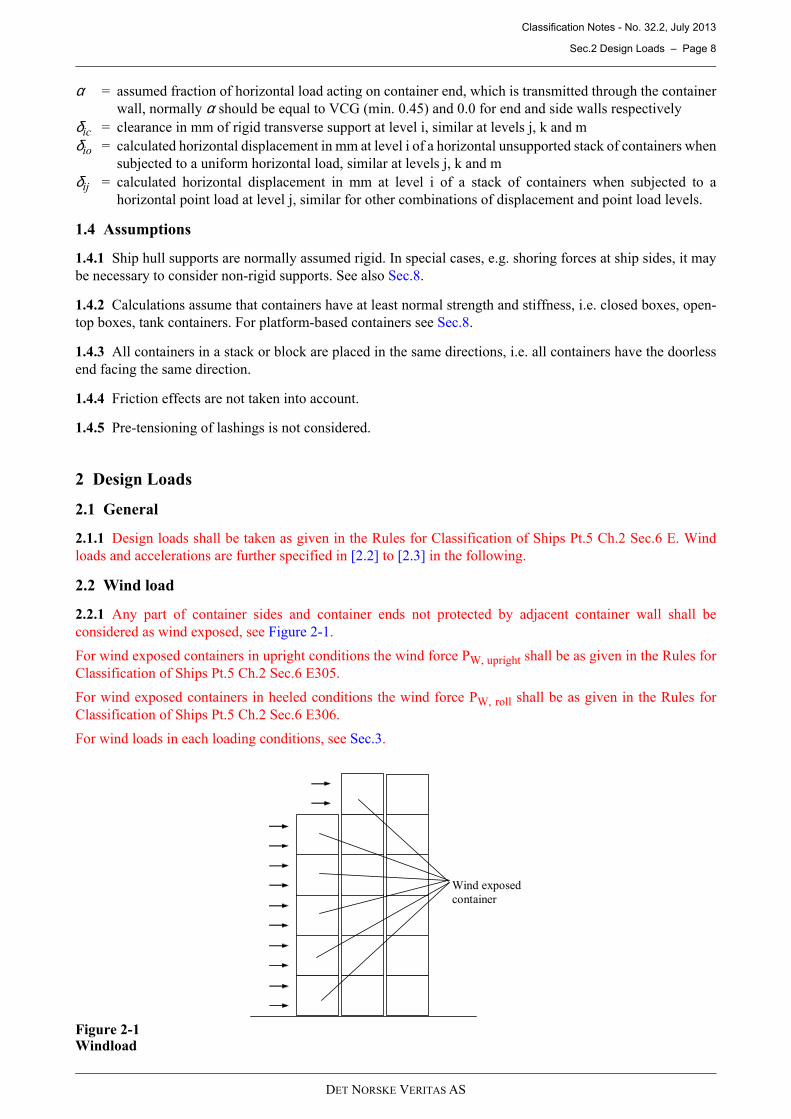
2.2.1 Any part of container sides and container ends not protected by adjacent container wall shall be
considered as wind exposed, see Figure 2-1.
For wind exposed containers in upright conditions the wind force PW, upright shall be as given in the Rules for
Classification of Ships Pt.5 Ch.2 Sec.6 E305.
For wind exposed containers in heeled conditions the wind force PW, roll shall be as given in the Rules for
Classification of Ships Pt.5 Ch.2 Sec.6 E306.
For wind loads in each loading conditions, see Sec.3.
Figure 2-1Windload
Wind exposed
container
DET NORSKE VERITAS AS

Classification Notes - No. 32.2, July 2013
Sec.3 Loading Conditions – Page 9
2.3 Accelerations
2.3.1 Accelerations shall be computed according to the Rules for Classification of Ships Pt.5 Ch.2 Sec.6 E300.If individual accelerations are to be applied the calculation procedures given in App.C shall be followed.
3 Loading Conditions
3.1 General
3.1.1 Applicable loading conditions are listed in Table 3-1. In the subsequent sections the relevant loadingconditions will be described in more detail.
3.2 LC1: Transverse loading I
3.2.1 For deck stowage extreme transverse accelerations are combined with the acceleration of gravity actingdownwards.
Wind loads shall be added to wind exposed containers.
See also Figure 3-1.
3.2.2 For hold stowage extreme transverse accelerations are combined with the acceleration of gravity actingdownwards.
See also Figure 3-1.
Figure 3-1Load case 1
3.3 LC2: Vertical loading
3.3.1 For deck stowage extreme vertical accelerations are combined with the acceleration of gravity actingdownwards.
See also Figure 3-2.
3.3.2 For hold stowage extreme vertical accelerations are combined with the acceleration of gravity actingdownwards.
See also Figure 3-2.
Table 3-1 Load case overview
LC Description Vertical Horizontal Wind
1 Transverse loading I g at PW, upright
2 Vertical loading g + av - No
3 Transverse loading II g cos(φ) at PW, roll
4 Longitudinal loading g al PW, upright
Pw, upright
M g
M
M at
DET NORSKE VERITAS AS

Classification Notes - No. 32.2, July 2013
Sec.3 Loading Conditions – Page 10
Figure 3-2Load case 2
3.4 LC3: Transverse loading II
3.4.1 For deck stowage extreme transverse accelerations are combined with the vertical component ofacceleration of gravity acting downwards.
Wind loads shall be added to wind exposed containers.
See also Figure 3-3.
3.4.2 For hold stowage extreme transverse accelerations are combined with the vertical component ofacceleration of gravity acting downwards.
See also Figure 3-3.
Figure 3-3Load case 3
3.5 LC4: Longitudinal loading
3.5.1 For deck stowage extreme longitudinal accelerations are combined with the acceleration of gravityacting downwards.
Wind loads shall be added to wind exposed containers.
See also Figure 3-4.
3.5.2 For hold stowage extreme longitudinal accelerations, are combined with the acceleration of gravityacting downwards.
See also Figure 3-4.
Figure 3-4Load case 4
M (av+g)
M
Pw, roll
M g cosφ
M
M at
M g φ
Pw, upright
M g
M
M al
DET NORSKE VERITAS AS

Classification Notes - No. 32.2, July 2013
Sec.4 Acceptance Criteria – Page 11
4 Acceptance Criteria
4.1 General
4.1.1 Container strength ratings shall be in accordance with recognized standards. In [4.2] strength ratings forISO containers are given.
Container securing devices shall be certified. Allowable forces in the container securing devices shall be takenas the certified MSL. [4.3] shows typical MSL for selected container securing devices.
4.2 Containers
4.2.1 Container strength limits shall normally be in accordance with the required minimum (tested) strengthvalues and capabilities given in ISO-standard 1496-1. Container fittings strength limits shall normally be inaccordance with ISO-standard 1161. Strength ratings are given in Table 4-1.
Table 4-1 Strength ratings
Standard ISO
20 ft 40 ft
Racking force door end 150 150
Racking force doorless end 150 150
Racking force side walls 150 (75*) 150 (75*)
Corner post compression 848 848
Vertical tension in top corner (from locking device) 250 250
Vertical tension in bottom corner (from locking de-vice)
250 250
Lashing loads in corner casting (in plane of cont. wall)
Horizontal 225 225
Vertical 300 300
Horizontal shoring forces on corners (perp. to cont. wall)
Lower corner, tension 200 250
Lower corner, compression 500 500
Upper corner, tension 200 250
Upper corner, compression 340 340
* For non-closed box containers
DET NORSKE VERITAS AS

Classification Notes - No. 32.2, July 2013
Sec.4 Acceptance Criteria – Page 12
Figure 4-1Strength ratings for 20'/40' containers
4.3 Container securing devices
4.3.1 Maximum Securing Load (MSL) in container securing devices shall not exceed 50% of the minimumbreaking load.
Table 4-2 shows typical values of MSL for selected types of container securing devices. For calculationpurposes certified values shall be used.
150/150 kN
150/150 kN
150/150 kN
150/150 (75/75*) kN
150/150 (75/75*) kN
150/150 (75/75*) kN
848/848 kN
848/848 kN
250/250 kN
250/250 kN
200/250 kN
200/250 kN
500/500 kN
500/500 kN
200/250 kN
200/250 kN
340/340 kN
340/340 kN
225/225 kN 225/225 kN
300/300 kN 300/300 kN
DET NORSKE VERITAS AS
Classification Notes - No. 32.2, July 2013
Sec.4 Acceptance Criteria – Page 13
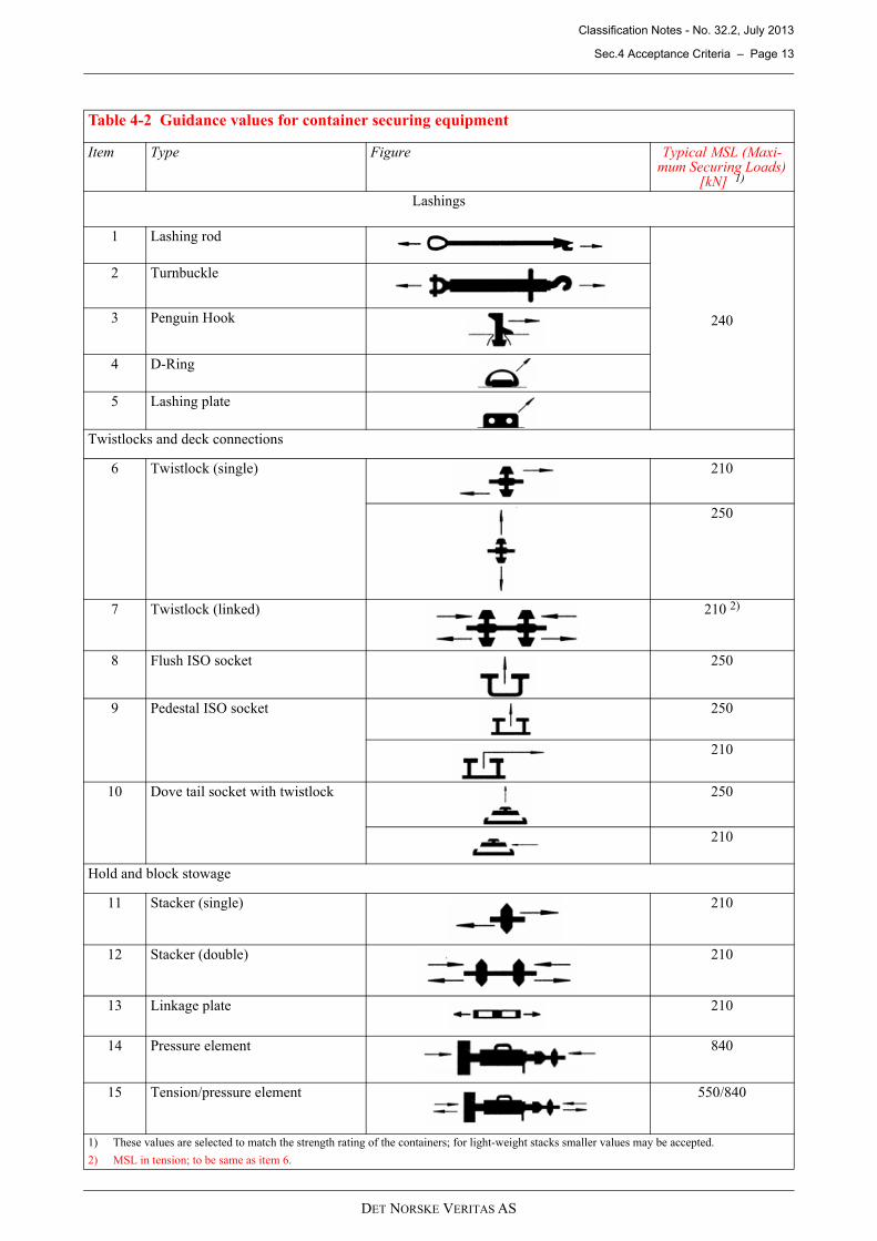
Table 4-2 Guidance values for container securing equipment
Item Type Figure Typical MSL (Maxi-mum Securing Loads)
[kN] 1)
Lashings
1 Lashing rod
240
2 Turnbuckle
3 Penguin Hook
4 D-Ring
5 Lashing plate
Twistlocks and deck connections
6 Twistlock (single) 210
250
7 Twistlock (linked) 210 2)
8 Flush ISO socket 250
9 Pedestal ISO socket 250
210
10 Dove tail socket with twistlock 250
210
Hold and block stowage
11 Stacker (single) 210
12 Stacker (double) 210
13 Linkage plate 210
14 Pressure element 840
15 Tension/pressure element 550/840
1) These values are selected to match the strength rating of the containers; for light-weight stacks smaller values may be accepted.
2) MSL in tension; to be same as item 6.
DET NORSKE VERITAS AS

Classification Notes - No. 32.2, July 2013
Sec.5 Direct Calculation using Beam Analysis – Page 14
4.4 Ship local supporting structures
4.4.1 The local supporting structures of fixed container securing devices in way of ship structures, such ashatch covers, decks, inner bottom and bulkheads shall be evaluated according to the Rules for Classification ofShips Pt.5 Ch.2 Sec.6 E700.
5 Direct Calculation using Beam Analysis
5.1 General
5.1.1 This section provides guidance on how to perform beam analysis for container lashing arrangements. Seealso Appendix B for examples.
5.1.2 The procedure described below represents the method used by the program NAUTICUS ContainerSecuring.
5.1.3 The container stacks are modelled as two independent 2-dimensional beam models, one for the door endand one for the doorless end, to incorporate the different racking stiffness.
Each stack may be analysed separately unless there are horizontal connections between the stacks such asdouble stackers or bridge fittings, in which case the whole block needs to be analysed.
5.1.4 For individual container stacks clearances of stack fittings may in general be ignored.
For lashings attached to lashing bridge the effect of relative movement of the hatch cover and the ship structureshall be accounted for in the analysis. This effect may be included for by a reduction of the lashing MSL inaccordance with [8.4].
For individual container stacks with vertical lashings and/ or external lashings the vertical twistlock clearancesshall be included in the analysis and are described more in detail in [8.5].
For horizontal supports of container stacks and container blocks the horizontal clearances of the horizontalsupport shall be included in the analysis.
For container stacks linked together horizontally by double stackers and/ or bridge stackers forming containerblocks the horizontal clearances of the horizontal linking elements shall be included in the analysis.
5.2 Modelling of geometry
5.2.1 The analysis shall take into account the flexibility of the containers. Unless otherwise specified, theracking stiffness Kc of container end walls for normal closed box ISO containers shall be taken as:
Kc = 10 kN/mm for doorless ends
Kc = 3.85 kN/mm for door ends
Unless otherwise specified, the racking stiffness of container sidewalls may be taken equal to doorlesscontainer end walls.
The corner posts shall be modelled with a shear area so that the correct racking stiffness is obtained, accordingto Figure 5-1. The bending stiffness of the beams should be high in order to avoid introduction of bendingstresses in the elements.
Figure 5-1Racking stiffness of container
When a force F (3.85 kN for the door end and 10 kN for the doorless end), is applied to the container thecalculated deflection shall be 1 mm.
δ
F
DET NORSKE VERITAS AS

Classification Notes - No. 32.2, July 2013
Sec.5 Direct Calculation using Beam Analysis – Page 15
5.2.2 Twistlocks shall be modelled with an area sufficiently large to avoid large tensile deformations.
The twistlocks shall be modelled with a hinge at one end to avoid transfer of bending moments between thecontainers, as shown in Figure 5-2.
Figure 5-2Hinge at end of twistlock
5.2.3 Stacking cones shall modelled as twistlocks with the difference that these must be modelled as non-linearelements capable of taking compression and shear but not tension.
5.2.4 Linking elements, such as double stackers and bridge stackers shall be modelled with the actual crosssectional area. The transverse elements should be positioned at the midpoint of the twistlock/ stacking cone andin general be fitted with hinges at both ends, as shown in Figure 5-3. For components that have the capabilityto transfer vertical shear forces, these hinges should be omitted. Gaps in the linking elements shall be modelledas nonlinearities.
Figure 5-3Linking elements and double stackers
5.2.5 Buttress supports, such as tension/pressure element and pressure element shall be modelled with theactual cross sectional area. Pure compression elements shall be modelled as nonlinear elements takingcompression only. In addition, the gap between the element and the supporting structure shall be modelled asnonlinearity.
Hull deformations, if significant, shall be taken into account when determining the shoring forces.
5.2.6 For ordinary lashing units with one turnbuckle, the lashings shall be modelled as beam elements withcharacteristics according to Table 5-1. The lashings elements shall be fitted with hinges at corner fitting endsto avoid transfer of bending moments, as shown in Figure 5-4.
Table 5-1 Lashing rod characteristics
Area Modulus of elasticity [N/mm2]
Rod lashing Actual area of rod 14 (l+6500) maximum 2.06 ×10⁵
l = The length of lashing including turnbuckle, in mm
Twist lock
Hinge
Hinge
Linking elements
Twist lock Link
Hinge
DET NORSKE VERITAS AS
Classification Notes - No. 32.2, July 2013
Sec.6 Formula based Analysis, Basic Formulae – Page 16
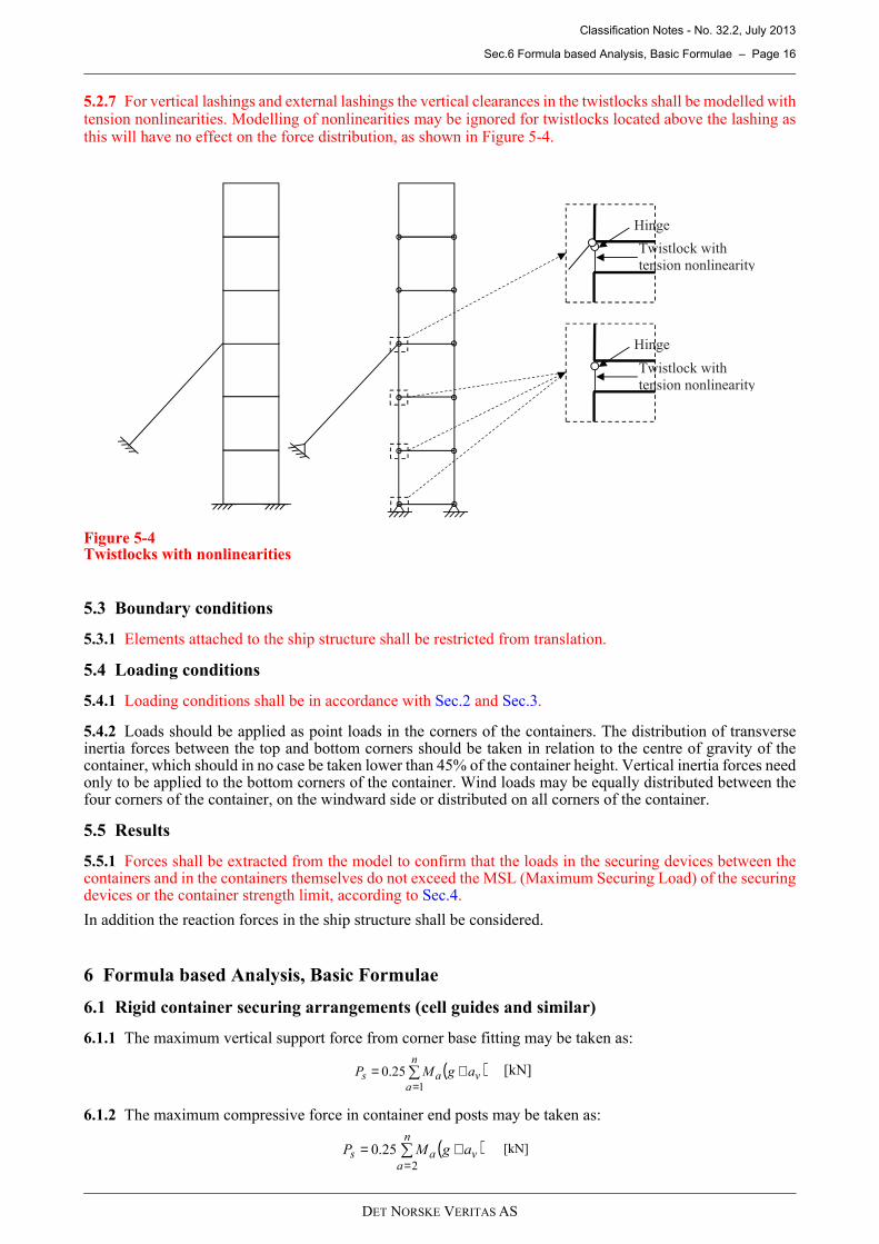
5.2.7 For vertical lashings and external lashings the vertical clearances in the twistlocks shall be modelled withtension nonlinearities. Modelling of nonlinearities may be ignored for twistlocks located above the lashing asthis will have no effect on the force distribution, as shown in Figure 5-4.
Figure 5-4Twistlocks with nonlinearities
5.3 Boundary conditions
5.3.1 Elements attached to the ship structure shall be restricted from translation.
5.4 Loading conditions
5.4.1 Loading conditions shall be in accordance with Sec.2 and Sec.3.
5.4.2 Loads should be applied as point loads in the corners of the containers. The distribution of transverseinertia forces between the top and bottom corners should be taken in relation to the centre of gravity of thecontainer, which should in no case be taken lower than 45% of the container height. Vertical inertia forces needonly to be applied to the bottom corners of the container. Wind loads may be equally distributed between thefour corners of the container, on the windward side or distributed on all corners of the container.
5.5 Results
5.5.1 Forces shall be extracted from the model to confirm that the loads in the securing devices between thecontainers and in the containers themselves do not exceed the MSL (Maximum Securing Load) of the securingdevices or the container strength limit, according to Sec.4.
In addition the reaction forces in the ship structure shall be considered.
6 Formula based Analysis, Basic Formulae
6.1 Rigid container securing arrangements (cell guides and similar)
6.1.1 The maximum vertical support force from corner base fitting may be taken as:
6.1.2 The maximum compressive force in container end posts may be taken as:
Twistlock with
tension nonlinearity
Hinge
Twistlock with
tension nonlinearity
Hinge
( )∑=
+=n
avas agMP
1
25.0 [kN]
( )∑=
+=n
avas agMP
2
25.0 [kN]
DET NORSKE VERITAS AS

Classification Notes - No. 32.2, July 2013
Sec.6 Formula based Analysis, Basic Formulae – Page 17
6.1.3 The stresses and forces in securing structures resulting from horizontal accelerations and wind forces, where
relevant, are to be calculated as M at + Pw and M al + Pw in transverse and longitudinal direction, respectively.
6.1.4 The analysis required for rigid container securing arrangements depends on the complexity of the
arrangement. For complex cellular securing structures, direct analysis may be necessary. In other cases manualcalculations will be sufficient.
6.1.5 Hull deformations, if significant, shall be taken into account when determining the shoring forces.
6.1.6 Container free ends of mixed stowage shall be considered as non-rigid securing arrangements in
accordance with [8.2].
6.2 Non-rigid securing arrangements (lashings and similar)
6.2.1 For non-rigid securing arrangements the vertical support forces, internal forces of the container stacks,
horizontal support forces and lashing forces are all to be calculated, if relevant.
6.2.2 The analysis shall take into account the flexibility of the containers. Unless otherwise specified, the
racking stiffness, Kc, of container end walls for normal closed-box ISO containers may be taken as:
Kc = 10 kN/mm for doorless ends
Kc = 3.85 kN/mm for door ends
Unless otherwise specified, the racking stiffness of container sidewalls may be taken equal to doorless
container end walls.
6.2.3 Calculations of container stacks or blocks shall be performed for both doorless and door end walls.
Normally maximum vertical and horizontal reaction forces at the stack base are found in doorless ends, whilst
maximum horizontal support forces and lashing forces are found in door ends.
6.2.4 The analysis shall be based on the elastic stiffness of lashings according to their type and dimensions,ref. [7.1.3].
6.2.5 For individual container stacks clearances of stack fittings may in general be ignored.
For lashings attached to lashing bridge the effect of relative movement of the hatch cover and the ship structure
shall be accounted for in the analysis. This effect may be included for by a reduction of the lashing MSL in
accordance with [8.4].
For individual container stacks with vertical lashings and/ or external lashings the vertical twistlock clearancesshall be included in the analysis and are described more in detail in [8.5].
For horizontal supports of container stacks and container blocks the horizontal clearances of the horizontal
support, δic given in [6.5], shall be included in the analysis.
For container stacks linked together horizontally by double stackers and/ or bridge stackers forming container
blocks the horizontal clearances of the horizontal linking elements, δb given in [6.5], shall be included in the
analysis.
6.2.6 The effects of vertical connections between the containers in a stack shall be taken properly into account.
The effects of possible tipping of container stacks without lock connection at bottom supports are of special
importance and must be especially considered. Reference is made to [6.2.10].
6.2.7 The calculations are to be based on analysis methods applicable to structures in general. In the analysisthe container walls may be considered as shear panels. The interaction between the two ends, or sides, of
containers may normally be assumed negligible. See also [8.2].
6.2.8 Generally, the horizontal force in each container end or side is to be taken as:
ah = at or al for transverse or longitudinal accelerations, respectively.
6.2.9 Maximum vertical support forces, racking forces, horizontal support forces and lashing forces may
normally be determined directly in accordance with Sec.7.
( )whh PaMP +⋅= 5.0 [kN]
DET NORSKE VERITAS AS

Classification Notes - No. 32.2, July 2013
Sec.6 Formula based Analysis, Basic Formulae – Page 18
6.2.10 The combined maximum vertical support forces may be determined as the larger of:
On compression side (positive):
or
On tension side (negative):
If Pst becomes negative tipping will take place and locking cones or twistlocks shall be installed.
Psh = calculated vertical support force due to horizontal loads as given in Sec.7ΣPsl = sum of the vertical components of relevant lashing forces according to Sec.7
On compression side ΣPsl is only added when internal cross lashing is usedOn tension side ΣPsl is only added when external lashing is used
6.2.11 The combined maximum compressive force in the lowermost container posts is normally determinedas the larger of:
and
Pch = calculated compressive force in post due to horizontal loads, equal to Psh vertical support force due tohorizontal loads as given in Sec.7, calculated at top of the container for which the container post is underinvestigation.
ΣPsl = as given in [6.2.10]
6.2.12 The racking force in the wall of the lowermost container is determined by:
ΣPr = sum of horizontal lashing or supporting forces (Pri, Prj etc.) calculated in accordance with Sec.7.Ph1 = horizontal force in lowermost container end
In cases where there are two or more containers above the upper lashing or fixed support, the racking force inthe lower of these should also be checked.
∑∑ ++==
slsh
n
aasc PPgMP
1
25.0 [kN]
( ) ∑
=
+ = n
a v a sc a g M P
1
25 . 0 [kN]
∑∑ +−==
slsh
n
aast PPgMP
1
cos25.0 φ [kN]
( )∑=
+=n
avac agMP
2
25.0 [kN]
∑∑ ++==
slch
n
aac PPgMP
2
25.0 [kN]
∑ ∑=
−+=n
arhhar PPPS
21α [kN]
DET NORSKE VERITAS AS

Classification Notes - No. 32.2, July 2013
Sec.6 Formula based Analysis, Basic Formulae – Page 19
6.3 Container stack with four flexible horizontal supports
6.3.1 Consider a container stack supported by lashings at levels i, j, k and m in that order from the bottom.
For the analysis in the following, reference is made to Figure 6-1.
Figure 6-1Four flexible supports, general case
6.3.2 Disregarding the lashings, the free horizontal displacement at level i is given by:
and similar for other levels j, k and m.
6.3.3 The horizontal displacement at level i due to a horizontal force acting at the same level is given by:
and similar for other levels j, k and m.
The displacement at levels below the force in question is proportional to the level number, e.g. the displacementat level i due to force acting at level k is given by:
The displacement at levels above the force in question is equal to the displacement at the force level.
6.3.4 The support force at level i is expressed as a function of the resulting horizontal displacement at the samelevel, i.e.:
and similar for levels j, k and m.
Km
Kk
Kj
Ki
Pm
Pk
Pj
Pi
δmm
δkk
δjj
δii
δmo
δko
δjo
δio
Ph6
Ph5
Ph4
Ph3
Ph2
Phk
n=6
+= ∑ ∑ ∑
= = +=
i
a
i
a
n
abhbha
cio PP
K 1 1 1
1 αδ
c
iii
K
Pi ⋅=δ
kkikk
i δδ =
( )[ ]iiijikimioiri KP δδδδδ +++−=
DET NORSKE VERITAS AS

Classification Notes - No. 32.2, July 2013
Sec.6 Formula based Analysis, Basic Formulae – Page 20
6.3.5 The horizontal forces as mentioned in [6.3.3] (Pi, Pj, Pk, Pm) must be equal to the corresponding supportforces given in [6.3.4] (Pri, Prj, Prk, Prm). Consequently the following linear equations may be derived, in matrixform:
From these equations the horizontal support forces Prm, Prk, Prj and Pri may be solved. If the number of lashingsis less than four, the system reduces correspondingly. E.g. for a system with two lashings the system reduces to:
6.4 Container stack with combined rigid and flexible horizontal supports
6.4.1 Consider a stack of containers as in [6.3]. Let one support be rigid, for example at level j. A clearance δjcat that support is assumed.
6.4.2 The support forces at levels i, k and m are given by the formulae in [6.3.4]. At level j the resultingdisplacement is given by:
Consequently the linear equations in [6.3.5] are modified as follows:
6.4.3 In this way the linear equations may be set up for an arbitrary combination of rigid and flexible supports.
For example, with four rigid supports the horizontal support forces are given by:
6.5 Container blocks
6.5.1 Container stacks connected by double stackers and/ or bridge stackers may be regarded as a block withrespect to lashing and rigid horizontal supports. It is assumed that the linking elements are fitted at each levelof horizontal support and that the clearances at stackers normally are negligible. The block may be calculatedon the basis of an analysis of single stacks with the same deflection (fixed support clearance). The resultinghorizontal support force will be the sum of all support forces from the individual stacks.
If the horizontal stackers are fitted with a clearance δb at each stacker, the support clearances δic, δjc, δkc or δlcare for each stack away from the rigid support to be increased by δb. Arrangement with a single rigid supportis shown in Figure 6-2.
- The diagonal element
- The displacement
=
+
+
+
+
cio
cjo
cko
cmo
ri
rj
rk
rm
i
c
j
c
k
c
m
c
K
K
K
K
P
P
P
P
iK
Kiii
ijK
Kjj
ijkK
Kk
ijkmK
K
δδδδ
=
+
+
cio
cjo
ri
rj
i
c
j
c
K
K
P
P
iK
Ki
ijK
K
δδ
+++−= iijjkkmmjojck
j
m
j δδδδδδ
jjK
K
j
c →
+
jcjojo δδδ −→
−−−−
=
cicio
cjcjo
ckcko
cmcmo
ri
rj
rk
rm
K
K
K
K
P
P
P
P
iiii
ijjj
ijkk
ijkm
)(
)(
)(
)(
δδδδδδδδ
DET NORSKE VERITAS AS

Classification Notes - No. 32.2, July 2013
Sec.6 Formula based Analysis, Basic Formulae – Page 21
Figure 6-2Block with single rigid horizontal support
6.5.2 If the number of stacks in a block is greater than 4 and bridge stackers are fitted at all levels in the block,a reduction in the horizontal support forces may be introduced due to the stackers giving a certain vertical shearrestraint. The final support forces may be found as:
Pri = calculated horizontal reaction force for blockCr = reduction factor as given in Table 6-1
The racking force, Sr, in the end wall of the lowermost container is to be calculated according to [6.2.12] withthe reduced Prif inserted in the formula. The vertical support forces may be calculated with the uncorrected Pri.
6.5.3 In order to reduce the horizontal support forces at rigid block supports, the supports may be arranged forabsorbing both compression and tension. If the clearances at the individual stackers are considered to benegligible, a 50% distribution between the compression and tension side may normally be used whencalculating the support forces according to [6.5.1] and [6.5.2].
In case there is a clearance in each horizontal bridge stacker, redistribution towards 100% compression willtake place. A 50% distribution may be achieved by omitting all bridge stackers between middle stacks, thusobtaining two individual blocks.
Table 6-1 Reduction factors
nb 1 to 4 5 6 7 8 9 ≥10
Cr 1 0.98 0.95 0.91 0.85 0.79 0.75
δic
Pri
δio Bridge stackers
clearance: δb
n=6
i=5
Psh
rirrif PCP ⋅=
DET NORSKE VERITAS AS

Classification Notes - No. 32.2, July 2013
Sec.7 Formula based Analysis, Derived Formulae – Page 22
7 Formula based Analysis, Derived Formulae
7.1 General
7.1.1 The following describes elementary formulae for the analysis of container stacks subjected to horizontal
forces. In general, the formulae may be applied for the determination of vertical support forces, horizontal
support forces and lashing forces. It should be noted that the formulae for vertical support forces in this section
do not include the vertical component of possible lashing forces and vertical mass forces. These vertical
components are to be included in addition, according to [6.1.1], [6.1.2], [6.2.10] and [6.2.11].
7.1.2 The calculation formulae are based on the following assumptions:
— The bending stiffness of the container wall is assumed to be significantly higher than the shear stiffness;the container walls are therefore considered as shear panels
— Internal clearances in stacking and locking members of individual stacks are ignored
— Tensile vertical forces are assumed taken by lock stackers; if lock stackers are not fitted and containers maybe subject to tilting, the lashing forces will have to be specially considered
— The flexibility of container walls and lashings are assumed to be linear
— Pre-stressing of lashings is not included in the consideration
— Containers subjected to horizontal acceleration forces are assumed homogeneously loaded, with the centreof gravity in the centre point of the container. However a VCG of 45% of the container height may beutilised.
7.1.3 The horizontal spring stiffness of simple lashing rods supporting the container stack at level i may be
expressed as:
El = modulus of elasticity as per Table 5-1
Al = section area of lashing in mm2
ll = lashing length in mm
hl = vertical projection of lashing length in mm
sl = horizontal projection of lashing length in mm
The modulus of elasticity of non-standardised lashing equipment, such as wires and chains, will be subject to
special consideration, and may have to be determined experimentally.
Figure 7-1Stiffness of simple lashing
3
322
2
10)(
−×+
=ll
l
sh
sAEK
ll
i or 3
2
10sin −×=l
lli
l
AEK
γ kN/mm
Pli
δ
Kli
ll
sl
hl
i=3
γ
DET NORSKE VERITAS AS

Classification Notes - No. 32.2, July 2013
Sec.7 Formula based Analysis, Derived Formulae – Page 23
7.2 Container stack with single rigid support
7.2.1 A container stack with single rigid support is shown in Figure 7-2.
The clearance at the rigid support, δic, is assumed to be known. The unsupported displacement, δio, may becalculated with the formula in [6.3.2].
7.2.2 The horizontal support force derived from the general formulae in [6.4.3] is given by:
Not valid for δic > δio.
7.2.3 The vertical support force due to the horizontal forces are given by:
Figure 7-2Single rigid horizontal support
7.3 Container stack with two rigid horizontal supports
7.3.1 A container stack with two rigid supports is shown in Figure 7-3.
The clearances at the lower and higher supports, δic and δjc respectively, are assumed to be known. Theunsupported displacements, δio and δjo, may be calculated in accordance with the formulae in [6.3.2].
i
KP icioc
ri)( δδ −= [kN]
( )
s
n
ariha
shb
hiPPa
P
−−
=∑=1
5.0
[kN]
δic
δio
DET NORSKE VERITAS AS

Classification Notes - No. 32.2, July 2013
Sec.7 Formula based Analysis, Derived Formulae – Page 24
7.3.2 The horizontal support forces derived from the general formulae in [6.4.3] are given by:
At level i:
At level j:
If any of the support forces becomes negative, this support will not be engaged. The calculation then has to berepeated with the remaining support only, according to [7.2].
7.3.3 The vertical support forces due to the horizontal forces are given by:
Figure 7-3Two rigid horizontal supports
7.4 Container stack with three rigid horizontal supports
7.4.1 The clearances at the three supports, δic, δjc and δkc are assumed to be known. The unsupporteddisplacements, δio, δjo and δko, may be calculated in accordance with the formulae in [6.3.2].
( ) ( )[ ]( )iji
jiKP
iciojcjocri
−
−−−=
2
δδδδ[kN]
( ) ( )[ ]( )ij
KP
iciojcjocrj −
−−−=
δδδδ[kN]
( ) ( )s
n
arjriha
shb
hjPiPPa
P
+−−
=∑=1
5.0
[kN]
δjc
δjo
δic
δio
Prj
Pri
DET NORSKE VERITAS AS

Classification Notes - No. 32.2, July 2013
Sec.7 Formula based Analysis, Derived Formulae – Page 25
7.4.2 The horizontal support forces derived from the general formulae in [6.4.3] are given by:
At level i:
At level j:
At level k:
If any of the support forces becomes negative, this support will not be engaged. The calculation then has to berepeated with the remaining supports, according to [7.3].
7.4.3 The vertical support forces due to the horizontal forces are given by:
7.5 Container stack with single flexible support
7.5.1 A container stack with single flexible support is shown in Figure 7-4.
The horizontal spring stiffness of the lashing, Ki, may be calculated in accordance with the formula in [7.1.3].
The unsupported displacement, δio, may be calculated in accordance with the formula in [6.3.2].
7.5.2 The horizontal support force derived from the general formulae in [6.3.5] is given by:
7.5.3 The vertical support forces due to the horizontal forces may be calculated as given in [7.2.3].
Figure 7-4Single flexible horizontal support
( ) ( )[ ]( )iji
jiKP
iciojcjocri
−
−−−=
2
δδδδ[kN]
( ) ( )( )
( ) ( )( )
−−−−
−−
−−−=
jkijKP
jcjokckoiciojcjocrj
δδδδδδδδ[kN]
( ) ( )[ ]( )jk
KP
jcjokckocrk −
−−−=
δδδδ[kN]
( ) ( )s
n
arkrjriha
shb
hkPjPiPPa
P
++−−
=∑=1
5.0
[kN]
+
=i
K
K
KP
i
c
iocri
δ[kN]
Ki Pri
δio
DET NORSKE VERITAS AS

Classification Notes - No. 32.2, July 2013
Sec.7 Formula based Analysis, Derived Formulae – Page 26
7.6 Container stack with one rigid and one flexible support
7.6.1 A container stack with one rigid and one flexible support is shown in Figure 7-5.
The horizontal spring stiffness of the lashing, Ki, may be calculated in accordance with the formula in [7.1.3].
The clearance at the rigid support, δic, is assumed to be known.
The unsupported displacements, δio and δjo, may be calculated in accordance with the formulae in [6.3.2].
7.6.2 The horizontal support forces derived from the general formulae in [6.3.5] and [6.4.3] are given by:
At level i:
At level j:
7.6.3 The vertical support forces due to the horizontal forces may be calculated as given in [7.3.3].
Figure 7-5One rigid and one flexible support
7.7 Container stack with two flexible horizontal supports
7.7.1 A container stack with two flexible horizontal supports is shown in Figure 7-6.
The horizontal spring stiffness of the lashing, Ki and Kj, may be calculated in accordance with the formula in[7.1.3].
The unsupported displacements, δio and δjo, may be calculated in accordance with the formulae in [6.3.2].
( )[ ]ji
K
Ki
jiKP
i
c
iojcjocri
+−
−−=
2
δδδ[kN]
( )2iji
K
K
iiK
KK
P
i
c
iojcjoi
cc
rj
−
+
−−
+
=δδδ
[kN]
Ki Pri
δio
δjc
δjo
Prj
DET NORSKE VERITAS AS

Classification Notes - No. 32.2, July 2013
Sec.7 Formula based Analysis, Derived Formulae – Page 27
7.7.2 The horizontal support forces derived from the general formulae in [6.3.5] are given by:
At level i:
At level j:
7.7.3 The vertical support forces due to the horizontal forces may be calculated as given in [7.3.3].
Figure 7-6Two flexible horizontal supports
7.8 Container stack with one rigid and two flexible horizontal supports
7.8.1 A container stack with one rigid and two flexible supports is shown in Figure 7-7.
The horizontal spring stiffness of the lashing, Ki and Kj, may be calculated in accordance with the formula in[7.1.3].
The clearance at the rigid support, δkc, is assumed to be known.
The unsupported displacements, δio, δjo and δko, may be calculated in accordance with the formulae in [6.3.2].
7.8.2 The horizontal support forces derived from the general formulae in [6.3.5] and [6.4.3] are given by:
At level i:
+
+−
+−
=
jK
Ki
K
Ki
jK
KiK
P
j
c
i
c
ioj
cjoc
ri
2
δδ[kN]
2ij
K
Ki
K
K
iiK
KK
P
j
c
i
c
iojoi
cc
rj
−
+
+
−
+
=δδ
[kN]
Ki Pri
δio
δjo
Prj Kj
( )( ) ( ) ( )( ) ( ) 22
2
2 iCkjCjkC
kjijkCiCjKP
jij
jojiojkckocri
−−+−
−+−+−−=
δδδδ[kN]
DET NORSKE VERITAS AS

Classification Notes - No. 32.2, July 2013
Sec.7 Formula based Analysis, Derived Formulae – Page 28
At level j:
At level k:
7.8.3 The vertical support forces due to the horizontal loads and forces may be calculated as given in [7.4.3].
7.9 Container stack with three flexible horizontal supports
7.9.1 The horizontal spring stiffness of the lashing, Ki, Kj and Kk, may be calculated in accordance with theformula in [7.1.3].
The unsupported displacements, δio, δjo and δko, may be calculated in accordance with the formulae in [6.3.2].
7.9.2 The horizontal support forces derived from the general formulae in [6.3.5] are given by:
At level i:
At level j:
At level k:
( )( ) ( ) ( )( ) ( ) 22
22
2 iCkjCjkC
ikCkjijCiKP
jij
ijoioikckocrj
−−+−
−+−+−−=
δδδδ[kN]
( )( ) ( ) ( )( ) ( ) 22
22
2 iCkjCjkC
jCiCjiiCCKP
jij
ijojiojikckocrk
−−+−
−+−+−−=
δδδδ[kN]
iK
KC
i
ci +=
jK
KC
j
cj +=
( ) ( ) ( )( )kjikji
kjiokjojkocri
CCjiCjCCC
jCCCjiCjiKP
−−+−
−+−+−=
222
2δδδ[kN]
( ) ( ) ( )( )kjikji
kiokijoikocrj
CCjiCjCCC
CjiiCCjCiKP
−−+−
−+−+−=
222
22 δδδ[kN]
( ) ( ) ( )( )kjikji
jioijojikocrk
CCjiCjCCC
CjijCiiCCKP
−−+−
−+−+−=
222
22 δδδ[kN]
iK
KC
i
ci +=
jK
KC
j
cj +=
kK
KC
k
ck +=
DET NORSKE VERITAS AS

Classification Notes - No. 32.2, July 2013
Sec.7 Formula based Analysis, Derived Formulae – Page 29
7.9.3 The vertical support forces due to horizontal loads and forces may be calculated as given in [7.4.3].
Figure 7-7Container stack with one rigid and two flexible supports
Kj Prj
δjo
δkc
δko
Prk
Ki Pri
δio
DET NORSKE VERITAS AS

Classification Notes - No. 32.2, July 2013
Sec.8 Special Container Arrangements – Page 30
8 Special Container Arrangements
8.1 General
8.1.1 In this section some special cases of container arrangements are presented with applicable analysismethods. These methods are in addition to those described in the previous sections.
8.2 20' container in 40' cell guides
8.2.1 20' containers may be carried in cell guides designed for 40' containers provided that they are secured inaccordance with Rules for Classification of Ships Pt.5 Ch.2 Sec.6 D200.
The 20' containers shall have steel walls and top, i.e. not of open-frame type.
8.2.2 The cell guide end of 20' containers shall be considered as rigid container securing arrangement applyingLC2 given in Table 3-1.
The free end of 20' containers shall be considered as non-rigid container securing arrangement applying LC1to LC4 given in Table 3-1.
8.2.3 Maximum container weights in 20' stacks are normally determined by the racking force limit (see Table4-1) of the lowermost container in LC1 (ref. [3.2]).
The racking force in the lowermost 20' container is determined by summing the transverse forces from each 20'container. The contribution from the lowermost container should be taken equal to the fraction α,corresponding to the VCG.
8.2.4 The dynamic transverse forces in each tier shall be assumed distributed 35% to the free end and 65% tothe cell guide end, provided that the stack is topped by at least one 40' container.
If the 20' stack is not topped by a 40' container, the dynamic transverse force distribution shall be taken as 45%to the free end and 55% to the cell guide end.
8.3 40' container in 45' cell guides
8.3.1 40' containers may be carried in cell guides designed for 45' containers provided that they are secured inaccordance with Rules for Classification of Ships Pt.5 Ch.2 Sec.6 D200.
The 40' containers shall have steel walls and top, i.e. not of open-frame type.
8.3.2 The cell guide end of 40' containers shall be considered as rigid container securing arrangement applyingLC2 given in Table 3-1.
The free end of 40' containers shall be considered as non-rigid container securing arrangement applying LC1to LC4 given in Table 3-1.
8.3.3 Maximum container weights in 40' stacks are normally determined by the racking force limit (see Table4-1) of the lowermost container in LC1 (ref. [3.2]).
The racking force in the lowermost 40' container is determined by summing the transverse forces from each 40'container. The contribution from the lowermost container should be taken equal to the fraction α,corresponding to the VCG.
8.3.4 The transverse dynamic forces on each tier shall be assumed distributed 50% to the free end and 50% tothe cell guide end.
DET NORSKE VERITAS AS

Classification Notes - No. 32.2, July 2013
Sec.8 Special Container Arrangements – Page 31
8.4 Effectiveness of lashings attached to lashing bridge
8.4.1 When a lashing is attached to a lashing bridge the relative movement of the hatch cover and the shipstructure will give rise to increased loads in the lashing. To account for this phenomenon in the calculations,the MSL of the lashing is in general to be reduced according to Table 8-1.
8.4.2 Specialised arrangements with extreme lashing angles or unusually long distance between lashing bridgeand container are to be specially considered.
8.5 External lashings and vertical lashings
8.5.1 For a stack with internal lashings subject to transverse racking forces and rolling, the induced lashingforce will set up a vertical compression force in the corner post in addition to the vertical compression forceinduced by racking and rolling (see Figure 8-1).
For a stack with external lashings subject to transverse racking forces and rolling, the induced lashing forcewill set up a vertical compression force in the corner post counteracting the vertical tension force in corner postinduced by racking and rolling (see Figure 8-1).
For stacks where the corner post forces are the governing criteria (typically high stacks with homogenousweight distribution), a lashing arrangement with external lashings will in general allow for heavier stacks. Anexternal lashing arrangement will in general give greater lashing forces than an internal lashing arrangement.
For a stack subject to transverse forces and rolling, a vertical lashing will set up a compression force in thecorner post counteracting the vertical tension post force induced by racking and rolling (see Figure 8-1). Thehorizontal component of the vertical lashing force may be ignored. Vertical lashings are in general applied tooutermost wind exposed stacks.
Figure 8-1Internal lashing, external lashing and vertical lashing
Table 8-1 Reduction of MSL
Length between torsional constrains1) 20' container stack2) 40' container stack5)
Single island Twin island Short lashing 3) Long lashing 4) Short lashing 3) Long lashing 4)
Up to 5 Up to 5 10% 0% 15% 0%
6 to12 6 to 10 15% 0% 20% 0%
More than 12 More than 10 20% 0% 25% 0%
1) Number of 40’ bays between torsional constrains i.e. deck house or funnel. HFO tanks in 40’ bays not extending up to upper deck shall normally not be defined as a torsional constrain
2) Assuming ISO-lashing gap at mid hold is applied for the stowage, otherwise values as 40’ stack should be utilised
3) Lashing from lashing bridge to first tier above
4) Lashing from lashing bridge to second tier above
5) For hatch covers not fitted with ISO-lashing gap the values as 20’ stack may be applied
Internal lashing External lashing Vertical lashing with
internal lashing
DET NORSKE VERITAS AS

Classification Notes - No. 32.2, July 2013
Sec.8 Special Container Arrangements – Page 32
8.5.2 For vertical lashings and external lashings the vertical clearances between the container cornerconnections (bottom corner fitting - twistlock - top corner fitting or ISO socket) shall be considered in thestrength evaluation of the securing arrangements.
For corner connections with such lashing arrangement subject to tension forces, the vertical tension forces willbe taken by the lashing only until the vertical clearances in the locks are same as vertical lashing rod elongation.Consequently, these “pre-deformations” will result in additional tension forces in lashings.
8.5.3 The vertical clearance between bottom corner fitting - twistlock - top corner fitting or ISO containersocket shall be established considering the following parameters:
— Thickness of corner fitting in contact with the twistlock shall be taken in accordance with ISO-1161: 1984deducting allowable tolerance, i.e.19 mm.
— Distance between the base plate and the locking cone in the applied twistlock.
8.5.4 For arrangements with external lashings and vertical lashings; when strength evaluation is carried inaccordance with Sec.5 (Direct Calculation using Beam Analysis), the vertical clearances shall be modelled byspecifying a nonlinear tension gap in the twistlocks between corner posts, see [5.2.7].
8.5.5 For arrangements with vertical lashing; when strength evaluation is carried out in accordance with Sec.7(Formula based Analysis, Derived Formulae), the simplified method given in Appendix B.3 may be appliedfor assessing the lashing force and the tension force in the locking device.
8.5.6 For arrangements with external lashings; when strength evaluation is carried out in accordance withSec.7 (Formula based Analysis, Derived Formulae) the effect of the vertical clearances may be accounted forby a reduction of MSL for the uppermost external lashing only:
The Ci factor should be established as a function of the vertical twistlock force, F, in way of the corner fittingwhere the uppermost external lashing is connected to the stack.
For a given lashing arrangement, functions as shown in Table 8-2 should be established.
8.6 Block stowage in hold without cell guides
8.6.1 Care must be taken so that the vertical and transverse support points of the containers are aligned withthe areas of the ship structure which have been reinforced for this purpose.
8.6.2 The effects of stowing mixed container heights in the holds must be specially considered, taking intoaccount the support points in the transverse bulkhead and side structure.
8.6.3 The effects of hull deflections due to sea loading are to be taken into account when calculating transverse
Table 8-2 Lashing factor Ci
Door end
Doorless end
Pli,incl = lashing force in accordance with Sec.5, including locking clearances, applying LC3Pli,incl = lashing force in accordance with Sec.5, excluding locking clearances, applying LC3f1 = twistlock force in way of the corner fitting where the uppermost external lashing is connected to the stack in
accordance with Sec.5, excluding locking clearances, applying LC3
.Pli and f1 should be established applying the following stowage:
— Vertical clearances according to [8.5.3]— Maximum container stack height according to container loading plan— Homogenous stack weight distribution— VCG of the individual containers taken as 45% of container height— GM as given in Rules for Classification of Ships Pt.3 Ch.1 Sec.4 B— Stack weight equal to the maximum allowable stack weight obtained in accordance with Sec.5, considering the
locking clearances
����′ =
����
��
�� > 0 = 1 + � ; �� ≤ 0 = 1
�� > 0 = 1 + � ; �� ≤ 0 = 1
�, � =
��� ,����
��� ,����− 1
�1
DET NORSKE VERITAS AS

Classification Notes - No. 32.2, July 2013
Sec.8 Special Container Arrangements – Page 33
shoring forces. This is especially important for vessels with long holds and where the ship side deflections arelarge. If the hull deflections are unknown a conservative assumption should be made.
8.6.4 Clearances in securing equipment between the securing equipment and the supporting structure must bespecified.
8.6.5 Container blocks in holds without transverse connections, only compression i.e. pads (OSHA adaption)should be specially considered since this equipment does not give any vertical shear restraint and hence thehorizontal support forces will be increased.
8.7 Platform-based containers with reduced stiffness
8.7.1 Platform-based containers generally have reduced transverse and longitudinal racking, which shall betaken into account in the analysis.
8.8 Containers placed on two hatches or on hatches and container stanchions
8.8.1 If containers are placed on two hatches or on hatches and container stanchions, the relative deformationsshall be accounted for in the arrangement by fitting overlong ISO sockets, or by including this deformation inthe lashing calculations.
DET NORSKE VERITAS AS

Classification Notes - No. 32.2, July 2013
Appendix A Approval of Lashing Computer System – Page 34
Appendix A
Approval of Lashing Computer System
A.1 Introduction
This is guidance to those who are involved in approval and certification of lashing computers for a specific ship,i.e. software manufacturers who wish to have their software approved for a specific vessel.
Guidance is also given for manufacturers who wish to have their software type approved.
A.2 Definitions
Lashing computer system
A lashing computer system is a computer-based system for calculation and control of container securingarrangements for compliance with the applicable strength requirements. The lashing computer system consistsof software (calculation program) and hardware (the computer on which it runs).
Approval and certification for a specific vessel
Approval of software means that DNV approves the software for a specific installation on board a specificvessel. The approval is based on a review and acceptance of design, calculation method, verification of storeddata and test calculation for the specific vessel.
Approval of the software is to be carried out for each specific vessel where the software is to be installed.
Approval of the software results in approved test conditions.
If the software is type approved, the review and acceptance of design is not necessary for each specific vessel.Only verification of user manual, stored data and test calculations for the specific vessel will then be carriedout.
Certification (installation testing) is carried out to ensure that the lashing computer system works properlyonboard the specific vessel, and to ensure that the correct approved version of the software has been installed.
Certification is to be carried out for each vessel where a lashing computer system has been installed.
Type approval
Type approval means that DNV has approved the design methods and specifications of the software in general.The type approval is given based on a review and acceptance of design, calculation methods and documentedtest results for at least two test vessels. A type approval certificate is issued.
In the type approval certificate it will be stated what kind of calculations the type approval covers.
In connection with approval for a specific vessel with type approved software, less documentation will berequired, and a lower fee will be charged.
A.3 General requirements
The approval and certification process includes the following procedures for each ship:
1) Approval of software which results in approved test conditions.
2) Approval of computer hardware, where necessary.
3) Certification of the installed lashing computer system, which results in a lashing computer certificate.
The approved test conditions are to be kept onboard together with the user manual and the lashing computercertificate.
The approved software is either installed on a type approved hardware, or it is to be installed on two nominatedcomputers. If two nominated computers are available, approval of the hardware may be waived, but bothnominated computers are subject to certification. In addition, computers that are to be a part of a ship’s networkshould be approved in accordance with other relevant requirements imposed by the Society.
The lashing computer is to be capable of producing printouts of the results numerically. These numeric valuesare to be presented both as absolute values and as a percentage of the allowable values.
All screen and hardcopy output data are to be presented in a clear and unambiguous manner, with identificationof the version number of the calculation program.
A.4 General hardware requirements
In case two nominated computers are used, these are to be equipped with separate screens and printers.
DET NORSKE VERITAS AS

Classification Notes - No. 32.2, July 2013
Appendix A Approval of Lashing Computer System – Page 35
A.5 General software requirements
It is recommended that the design and production of the calculation program be in accordance with appropriatequality standards.
The software is to present the relevant parameters of each container arrangement. The following is to bepresented:
1) Draught
2) GM value
3) Each container weight
4) Position of each container stack
5) Lashing arrangement
6) Forward visibility
7) Accelerations of each container
8) Strength limitation: Listing of obtained values compared with the limit values according to Sec. 4 (internalforces in containers, forces in securing equipment and forces in supports)
9) A clear warning is to be given if any of the strength limitations are not complied with
10) The data is to be presented as screen and hard copy output to the user in a clear and unambiguous manner.
The software is to reject input errors by the user. For instance, negative weight input on containers or containerspositioned outside the ship is not to be accepted.
The software and the stored characteristic data are to be protected against erroneous use. The software shouldbe written to ensure that these can not be altered by the user.
The software is to be user-friendly, with a graphic presentation of the container arrangement.
Any changes made to the software are to be made by the manufacturer or his appointed representative. TheSociety is to be informed immediately of any changes. Failure to advise of any modifications to the softwarewill invalidate the certificates issued. In such cases the modified software is to be reassessed in accordance withthe approval and certification procedure.
A.6 Documentation to submit for approval
A.6.1 Hardware documentation
Requirements in Rules for Classification of Ships Pt.4 Ch.9 shall be complied with.
If the hardware is to be type approved, documentation according to Rules for Classification of Ships Pt.4 Ch.9Sec.1 is to be submitted.
A.6.2 Software documentation
Approval of the test conditions is mainly based on comparing the input and the results of the softwarecalculations with values calculated by DNV. The difference is not to be greater than 5%, calculated accordingto the following:
((Value calculated by software) – (Value calculated by DNV)) / (Allowable) ≤ ±5%The documentation must be prepared in a language understood by the users. If this language is not English, atranslation into English shall be included.
All submitted documentation shall be identified with the following:
1) Name of vessel, name of yard, the yard building number and the DNV identification number of the ship forwhich the program applies
2) Program name, version number and version date
3) Program manufacturer and address
4) List of contents.
For each specific ship the following documentation shall be submitted:
1) User manual
2) Program description (not required for type approved software)
3) Test conditions
4) Stored characteristic data.
DET NORSKE VERITAS AS

Classification Notes - No. 32.2, July 2013
Appendix A Approval of Lashing Computer System – Page 36
The user manual is to contain:
1) A general description of the program denoting identification of the program and its version number stated
2) Where applicable, a copy of the type approval certificate
3) Hardware specification needed to run the program
4) Listing of error messages and warnings with instructions for actions to be taken by the user in each case
5) Listings of allowable strength limits with respect to the container, lashing equipment and ship
6) Example of calculation procedure supported by illustrations and sample computer output
7) Example of computer output of each screen display with explanatory text.
The program description is to contain the following:
1) Description of functionality, including flowcharts
2) Descriptions of calculation methods and principles.
Program description is not required for type approved software.
In some cases where the functionality and principles are not clear, the entire program may need to be submittedfor evaluation at the discretion of the Society.
The test conditions shall be as follows:
1) Typical stowage in hold
2) Mixed stowage, if applicable
3) Typical stowage on deck
4) Deck stowage with twistlocks only
5) Case with exceeded stack weight
6) Case with exceeded lashing force
7) Case with exceeded lifting force
8) An example where outboard stack is missing.
The stored characteristic data shall include the following:
1) Main dimensions of the ship
2) The position of each bay from the aft perpendicular
3) Strength limitations (for containers, lashing equipment and the ship)
4) General loading limitations.
A.7 Certification
Certification is carried out to ensure that the lashing computer system works properly onboard, and to ensurethat the correct approved version of the software has been installed.
The approved test conditions are to be tested on the lashing computer system in presence of a surveyor fromthe Society before the lashing computer certificate is issued.
During the test, the securing arrangements calculated on the installed lashing computer system are to be verifiedto be identical to the approved test conditions. If numerical output from the lashing computer system is atvariance with the approved test conditions, a certificate cannot be issued.
During the tests, at least one of the test conditions is to be built up from scratch, to ensure that the calculatingmethods function properly.
Where the hardware is not type approved, the test is to be carried out on both the first and the second nominatedcomputer prior to the issuance of the lashing computer certificate. Both of the nominated computers are to beidentified on the certificate.
After completion of satisfactory tests, the lashing computer certificate is to be issued.
The following is to be listed in the lashing computer certificate:
1) Name of vessel, name of yard, yard number and year of built for the vessel
2) Software name, software version
3) Software manufacturer name and address
4) Type approval certificate number, if relevant
DET NORSKE VERITAS AS

Classification Notes - No. 32.2, July 2013
Appendix A Approval of Lashing Computer System – Page 37
5) Hardware name, serial number and manufacturer
6) Name and serial number of the second nominated computer or type approval certificate number
7) Identification of the approved test conditions used for the certification.
The lashing computer certificate and the approved test conditions are to be kept onboard attached to the usermanual.
The certification shall be carried out onboard.
DET NORSKE VERITAS AS

Classification Notes - No. 32.2, July 2013
Appendix B Calculated Examples – Page 38
Appendix B
Calculated Examples
In this appendix the following calculated examples are given using both the direct analysis method and theformula-based method:
B.1 Three-tier stack with single lashing, no windload
B.2 Four-tier stack with two cross lashing, no windload (formula-based method).
B.3 Vertical lashing using formula-based method
B.1 Three-tier stack with single lashing
Formula-based method
Three-tier 40' standard ISO container stack with single cross lashing to top of tier 1, no wind load included, seeFigure B-1.
Figure B-1Three-tier stack with single lashing, no wind load
Horizontal force per container end:
Ph = ½ × 30 × 6.67 = 100 kN
Lashing (see [7.1.3]):
General data:
Container weights: 30 t (all tiers)
Twistlocks: MSL 250 kN (between each tier)
Lashing rods: Steel, diameter 25 mm
MSL 240 kN
Transverse accelerations:
Tier 1: 6.67 m/s2
Tier 2: 6.67 m/s2
Tier 3: 6.67 m/s2
Vertical acceleration:
Tier 1-3 7.60 m/s2
Roll angle, φ 27°
Al = 491 mm2
hl = 2591 mm
Ph
Ph
Ph n=3
i=1
Plsi
Pli
Ps Ps
DET NORSKE VERITAS AS

Classification Notes - No. 32.2, July 2013
Appendix B Calculated Examples – Page 39
Calculation for doorless end walls
End wall racking stiffness (see [6.2.2]): Kc = 10 kN/mm
Free displacement at level i (see [6.3.2]):
Horizontal support force of lashing (see [7.5.2]):
Vertical support force due to horizontal forces (see [7.2.3]):
Lashing force:
Vertical component of lashing force:
Combined vertical support forces (see [6.2.10]):
Compression side
=> Psc = 727.0 kN (into ship structure)
Tension Side (Psl = 0))
Twistlock with SWL= 250 kN.
Vertical support force due to horizontal forces on top of lowest container (see [6.2.11]):
Compressive force in lowermost container corner post (see [6.2.11]):
sl = 2438 mm
ll = 3558 mm
El = 14(l + 6500) = 14(3558 + 6500) = 140 812 N/mm2 = 140.8 kN/mm2
mmkNK j /13.9)24382591(
24384918.140
322
2
=+
⋅⋅=
( ) mm 25.0 1001001005.010
10
=++⋅=i
δ
)150(3.119
113.9
10
2510<=
+
⋅=riP
( )kNPsh 5.379
2258
25913.11911005.4 =⋅⋅−⋅=
)240(1.1742438
243825913.119
22
<=+=liP
)300(8.1262438
25913.119 <==slP
0.7278.1265.37981.930325.0 =++⋅⋅⋅=sc
P
Pst = 0.25·3·30·9.81·cos27°-379.5 = -182.8 ( > -250)
kNPch 5.229
2258
2591)1005.01005.1( =⋅⋅+⋅=
Pc = 0.25·2·30·9.81+229.5+126.8= 503.5kN ( < 848)
DET NORSKE VERITAS AS

Classification Notes - No. 32.2, July 2013
Appendix B Calculated Examples – Page 40
Racking force in lowest container (see [6.2.12]):
Calculation for door end walls
End wall racking stiffness (see [6.2.2]): Kc = 3.85 kN/mm
Free displacement at level i (see [6.3.2]):
Horizontal support force of lashing (see [7.5.2]):
Vertical support force due to horizontal forces (see [7.2.3]):
Lashing force:
Vertical component of lashing force:
Combined vertical support forces (see [6.2.10]):
Compression side
=> Psc = 722.1 kN (into ship structure)
Tension Side (Psl = 0)
Twistlock with SWL = 250 kN.
Vertical support force due to horizontal forces on top of lowest container (see [6.2.11]):
Compressive force in lowermost container corner post (see [6.2.11]):
Racking force in lowest container (see [6.2.12]):
)150(7.1303.1191005.01002 <=−⋅+⋅=rS
( ) mm 64.9 1001001005.085.3
10
=++⋅=i
δ
),150(8.175
113.9
85.3
9,6485.3OKNotPri >=
+
⋅=
kNPsh 6.314
2258
2591)8.17511005.4( =⋅⋅−⋅=
5.2562438
243825918.175
22
=+=liP (>240, Not OK)
)300(8.186
2438
25918.175 <==slP
Psc = 0.25·3·30·9.81+314.6+186.8 = 722.1
Pst = 0.25·3·30·9.81·cos27°-314.6 = -117.9 ( > -250)
kNPch 5.229
2258
2591)1005.01005.1( =⋅⋅+⋅=
Pc = 0.25·2·30·9.81+229.5+186.8= 563.5kN ( < 848)
Sr = 2·100+0.5·100-175.8= 74.2kN ( < 150)
DET NORSKE VERITAS AS

Classification Notes - No. 32.2, July 2013
Appendix B Calculated Examples – Page 41
Tipping moment/pull-out force for tier 2
Vertical support forces due to horizontal forces (see [7.2.3]):
Compression side
Tension Side
B.2 Four-tier stack with two cross lashingsFour-tier 40' standard ISO container stack with two cross lashings, no wind load included, see Figure B-2.
Figure B-2Four-tier stack with two cross lashings, no wind load
General data:
Twistlocks: MSL 250 kN (between each tier)
Lashing rods: Steel, diameter 25 mm
MSL 240 kN
MassTransverse acceleration, at:
Pha
Tier 1: 30 6.10 m/s2 91.5 kN
Tier 2: 30 6.25 m/s2 93.8 kN
Tier 3: 30 6.40 m/s2 96.0 kN
Tier 4: 3 6.55 m/s2 9.8 kN
Vertical acceleration:
Tier 1-3 4.20 m/s2
Roll angle, φ 25°
kNPsh 5.229
2258
2591)1005.01005.1( =⋅⋅+⋅=
kN 376.7 5.22981.930225.0 =+⋅⋅⋅=scP
Pst = 0.25·2·30·9.81·cos27°-229.5 = -98.4 ( > -250)
Ph4
n=4
i=1
j=2
Ph3
Ph2
Ph1
DET NORSKE VERITAS AS

Classification Notes - No. 32.2, July 2013
Appendix B Calculated Examples – Page 42
Lashings (see [7.1.3]):
Ei = 14 (3 558 - 6500) = 140 812 N/mm2 = 140.8 kN/mm2
Ej = 14 (l + 6500) = 14 (5727+6500) = 171 178 N/mm2 = 171.2 kN/mm2
Calculation for doorless end walls.
End wall racking stiffness (see [6.2.2]): Kc = 10 kN/mm
Free displacement at level i and j (see [6.3.2]):
Horizontal support force of lashing (see [7.7.2]):
Vertical support force (see [7.3.3]):
Lashing force:
mm 3558 24382591 22 =+=i
l
( ) mm 5727 243825912 22 =+⋅=j
l
mmkNKi
/13.9)24382591(
24384918.140
322
2
=+
⋅⋅=
( )mmkNK
j/66.2
)243825912(
24384912.171
322
2
=+⋅
⋅⋅=
( ) mm 24.5 8.90.968.935.915.010
10
=+++⋅=i
δ
( )( ) mm 39.8 8.90.968.938.90.968.935.915.010
10
=++++++⋅=j
δ
)150(5.91
266.2
101
13.9
101
5.24266.2
108.39110
2
<=
+
+−
+−⋅= kNPr i
)150(2.53
1266.2
101
13.9
10
5.2418.39113.9
1010
2
<=−
+
+
⋅−
+= kNPrj
( )kNPrj 6.301
2258
25912.5325.9118.95.3965.28.935.15.915.0=
⋅⋅−⋅−⋅+⋅+⋅+⋅=
)240(5.1332438
243825915.91
22
<=+= kNPli
)240(0.1252438
2438)25912(2.53
22
<=+⋅
= kNPlj
DET NORSKE VERITAS AS

Classification Notes - No. 32.2, July 2013
Appendix B Calculated Examples – Page 43
Vertical component of lashing force:
Combined vertical support forces (see [6.2.10]):
Compression side
=> Psc = 740.0 kN (into ship structure)
Tension Side (Psl = 0)
Twistlock with SWL = 250 kN.
Vertical support force due to horizontal forces on top of lowest container (see [6.2.11]):
Compressive force in lowermost container corner post (see [6.2.11]):
Racking force in lowest container (see [6.2.12]):
B.3 Vertical lashings using formula-based methodForce in wind lashing, Fδ
Force in twistlock/corner post, FT = FTOT - Fδ where:
FTOT = total force in twistlock/corner postFδ = force in vertical lashing due to clearances,
where:
δ = total clearance (i.e. sum of clearances in each combination of bottom corner fitting - twistlock - top cornerfitting or ISO socket, where clearances should be considered according to [8.5.3], see Fig.B-3)
L = length of vertical lashing, including turnbuckleE = effective E-modulus of vertical lashingA = cross section area of vertical lashing
)300(2.972438
25915.91 <== kNPsli
)300(1.1132438
259122.53 <=⋅= kNPslj
( ) kNPsc 0.7401.1132.976.30181.9330325.0 =+++⋅+⋅⋅=
Pst = 0.25·(3·30+3)·9.81·cos25°-301.6 = -94.9 ( > -250)
1.186
2258
2591)2.538.95.2965.18.935.0( =⋅−⋅+⋅+⋅=chP
Pc = 0.25·(2·30+3)·9.81+186.1+97.2+113.1= 550.9kN ( < 848)
)150(7.1002.535.918.90.968.935.915.0 <=−−+++⋅=r
S
L
AEF
⋅⋅= δδ
DET NORSKE VERITAS AS

Classification Notes - No. 32.2, July 2013
Appendix B Calculated Examples – Page 44
Figure B-3Sum of clearances in twistlock
Example:
Vertical lashing from deck to bottom of tier 2.
Data:
FTOT = 300 kN (From DNV Nauticus Hull spread sheet “Container Securing”, “Vertical forces in twistlock”)L = 2700 mmA = 491 mm2 (diameter 25 mm)E = 14 (l + 6500) = 14 (2700 + 6500) = 1.29 ×10 power 5 N/mm2
δ = 5 + 5 = 10 mm
Force in vertical lashing:
Force in twistlock/corner post:
Fδ = δ · E · A / L =10 · 1.29x105 · 491 / 2700 /1000 = 234.6kN (< 240kN)
FT = FTOT – Fδ = 300 – 234.6 = 65.4kN (< 250kN)
DET NORSKE VERITAS AS

Classification Notes - No. 32.2, July 2013
Appendix C Individual Accelerations for Lashing Calculations – Page 45
Appendix C
Individual Accelerations for Lashing Calculations
C.1 Objective
The objectives with applying individual accelerations and not Rule-defined accelerations as basis for strengthevaluation of container securing arrangements are:
— To allow for area dependent accelerations applying route specific wave scatter diagrams, resulting in loweraccelerations than as for worldwide trade.
— To allow for heavier container stacks, as the Rule-defined combined transverse acceleration has built-inconservatism.
— To represent a higher scientific engineering level, as accelerations are established based on wave loadanalysis representing ship specific hull form and mass distribution.
C.2 Scope
In order to apply individual accelerations for lashing calculations, the following shall be established:
— Combined transverse acceleration (mostly depending on container’s vertical position and to some extenton container’s longitudinal position);
— Combined vertical acceleration (mostly depending on container’s longitudinal position and to some extenton container’s transverse position); and
— Combined longitudinal acceleration (mostly depending on container’s vertical position and to some extenton the container’s transverse position).
C.3 Application
The strength evaluations of the container securing arrangements shall follow the calculation proceduresestablished in this Classification Note, applying individual accelerations. Strength limitations in containers andcontainer securing devices shall not be changed.
The individual accelerations shall be applied in a consistent manner: All accelerations are to be eitherindividual, or Rule-defined. Additionally, all container stowage shall be approved applying either individualaccelerations or Rule-defined accelerations.
The application of the individual accelerations is limited to strength evaluation of container securingarrangements only. The individual accelerations shall not be applied to hull structures supporting the containerstacks.
The individual accelerations may be applied to newbuildings and for ships in operation.
If the “Container Stowage and Securing Manual” is approved applying individual accelerations and the ship isequipped with a lashing computer certified in accordance with the procedures given in Appendix A, thecomputer shall apply individual accelerations and not Rule-defined accelerations.
C.4 Design basis for wave load analysis
The individual accelerations shall be established in accordance with the principles given in section 3 ofClassification Notes No. 34.1 “CSA – Direct Analysis of Ship Structures”. Extracts of design basis forindividual accelerations for worldwide trade are shown in Table C-1 and Table C-2.
The wave load analysis shall be run applying 5 knots and 2/3 of maximum service speed with all headings,stepped 30°. The combined vertical acceleration and the combined longitudinal acceleration shall be based on5 knots. The combined transverse accelerations shall be based on the speed giving the greater combinedtransverse acceleration (5 knots or 2/3 of maximum service speed).
For area dependent accelerations, same design basis as for worldwide trade shall be applied with the exemptionof applicable scatter diagram. A scatter diagram for the route shall be specified based on appropriate weightingof the route specific scatter diagrams given in Recommended Practice C-205 Environmental Conditions andEnvironmental Loads.
Table C-1 Design basis for wave load analysis
Design parameter
Return period
Scatter diagram
Wave spectrum
Wave spreading
Roll radius of gyration
Roll damping
Requirement 20 years North Atlantic3) Pierson-Moskowitz3) COS2 0.39 B1) Tanaka and Kato2)
1) As given in Rules for Ships Pt.3 Ch.1 Sec.4 B402
2) As given in Sec. 3.3 of CN 34.1; alternative roll damping method may be accepted, but shall not be taken greater than 3% of critical roll damping
3) As given in DNV-RP-C205
DET NORSKE VERITAS AS

Classification Notes - No. 32.2, July 2013
Appendix C Individual Accelerations for Lashing Calculations – Page 46
C.5 Selection of still water loading conditions for wave load analysis
The combined vertical acceleration and the combined longitudinal accelerations are not significantlydepending on the vessel’s still water conditions. The combined transverse acceleration is strongly dependingon the vessel’s GM value. The effect of draught and trim is limited. Therefore, in order to provide individualaccelerations for representative container loading conditions, the individual accelerations shall be provided fora certain range of GM values:
— Low GM, representing a homogenous container loading condition with number of containers in the rangeof the vessel’s full nominal container capacity.
— High GM, representing holds completely filled with heavy containers and few heavy containers on deck orhigher stacks on deck having a low vertical center of gravity.
— High-high GM, representing holds completely filled with very heavy containers and few very heavycontainers on deck, and is to represent the greatest GM value the vessel may be expected to in containerloading confditions.
The GM values to be applied as design basis should typically be in accordance with Table C-3.
If the vessel is having a special hull form resulting in that GM ranges are not well represented by Table C-3,GM values may be established in accordance with Table C-4.
The Low GM value should not significantly differ from the minimum GM value that will be applied in the“Container Stowage and Securing Manual”. The High GM should not significantly differ from greatest GMvalue that will be applied in “Container Stowage and Securing Manual”, if such is provided. If the vessel isbeing deployed in certain trades having GM ranges that not are well represented by Table C-3, other GM valuesas design basis for the individual accelerations will be considered.
Table C-2 Speed and heading to be applied in wave load analysis
AccelerationCombined transverse
accelerationCombined vertical
accelerationCombined longitudinal
acceleration
Vessel speed5 knots or 2/3 of max speed (speed
giving the greater acceleration)5 knots
Wave heading profile All headings, stepped 30°, with same time fraction of each heading
Table C-3 Typical GM values
GM value Draught GM
Low GM
High GM Tdesign2)
B ≤ 32.2 m1) B > 40.0 m1)
0.05 B 0.08 B
High-high GM Tdesign2)
B ≤ 32.2 m1) B > 40.0 m1)
0.10 B 0.16 B
1) With linear interpolation for B in between
2) Not to be taken less than 85% of scantling draught
Table C-4 Alternative method for establishing GM values
GM value Draught
On deck In holds
Container intake1)
TEU weight
CoG2) Container intake1)
TEU weight
CoG2)
Low GM5) Tdesign6) 100% x t/TEU4) 45% 100% x t/TEU4) 45%
High GM Tdesign6) y% 14 t/TEU3) y% × 45% = 0.45 y% 100% 14 t/TEU3) 45%
High-high GM Tdesign6) 10% z t/TEU4) 10% × 45% = 4.5% 100% z t/TEU4) 45%
1) Percentage of nominal TEU capacity according to container loading plan
2) Vertical CoG to be in percentage of maximum container stack height according to container loading plan
3) Not to be taken less than maximum homogenous TEU weight in loading manual
4) To be established assuming homogenous weight distribution with same weight in holds and on deck
5) Not to be taken less than 1.0 m
6) Not to be taken less than 85% of scantling draught
DET NORSKE VERITAS AS

Classification Notes - No. 32.2, July 2013
Appendix C Individual Accelerations for Lashing Calculations – Page 47
C.6 Reporting
The ship’s main dimensions, geometry and loading conditions shall be presented in the documentation.
When relevant, route specific scatter diagrams shall be presented along with weighting factors for the includedscatter diagram zones from DNV-RP-C205. The map of the environmental zones with the route marked on themap shall be included.
The resulting RAOs (all motions including surge, sway, heave, pitch, roll and yaw) and accelerations(longitudinal, transverse and vertical) shall be presented for North Atlantic scatter diagram, for each still waterloading condition and speed. The resulting RAOs shall be presented in graphical form to show responseamplitude (in m/m or deg/m) as functions of wave period (in s). An example is illustrated in Figure C-1.
If additional analyses for route specific scatter diagram is carried out, the resulting RAOs and acceleration shallbe presented similarly.
The combined accelerations shall also be presented in tabular form in accordance with Table C-5, Table C-6and Table C-7.
Figure C-1Example of diagrams for RAOs
DET NORSKE VERITAS AS

Classification Notes - No. 32.2, July 2013
Appendix C Individual Accelerations for Lashing Calculations – Page 48
C.7 Individual accelerations for GM value different from those applied in wave load analysis
For still water conditions differing from those applied in wave load analysis, liner interpolation betweenspecified GM values may be applied.
For GM values less than the Low GM extrapolation shall not be carried out. For small GM values the swaycomponent of the combined transverse acceleration (being independent of GM) is dominating. Therefore, anextrapolation for GM less than the Low GM will result in under predicting the combined transverseacceleration. For actual GM values below the Low GM the individual accelerations obtained for the Low GMshall be applied.
For GM values greater than the High-high GM linear extrapolation may in general be carried out. This will ingeneral result in over predicting the combined accelerations. However, for containers having a vertical centreof gravity below the roll axis of rotation the combined transverse acceleration may decrease with increased GM
Table C-5 Combined transverse acceleration for each Tier and 40' Bay
Tier No.
2 4 6 8 10 12 14 16 82 84 86 88 90 92 94 96 98
40' B
ay N
o.
2
Combined transverse acceleration are to be established for each Tier and for each 40’ Bay
6
10
14
18
22
26
30
34
38
42
46
50
54
58
Table C-6 Combined vertical acceleration for each 40' Bay and Row
40' Bay No.
2 6 10 14 18 22 26 30 34 38 42 46 50 54 58
Ro
w N
o.
14
Combined vertical acceleration are to be established for each 40’ Bay and for each Row
12
10
8
6
4
2
0
Table C-7 Combined longitudinal acceleration for each Tier and Row
Tier No.
2 4 6 8 10 12 14 16 82 84 86 88 90 92 94 96 98
Ro
w N
o.
14
Combined longitudinal acceleration are to be established for each Tier and for each Row
12
10
8
6
4
2
0
DET NORSKE VERITAS AS

Classification Notes - No. 32.2, July 2013
Appendix C Individual Accelerations for Lashing Calculations – Page 49
for high GM values (dynamic roll will counteract the sway and transverse component of gravity). Therefore,
linear extrapolation may be carried out, but shall not be taken less than the combined acceleration for the High-
high GM.
C.8 Individual accelerations applied in lashing computer
For still water conditions having a different GM value from those applied in wave load analysis the methods
specified in section [C.7] shall be applied.
As an alternative to tabulated individual accelerations approximation formulas may be applied. The
approximation formulas shall envelope all tabulated values. The approximation formulas should as a minimum
be on the following format:
Combined transverse acceleration:
— f(z) should be established for the bay amidships
— g(x) should be established for the tier with the greatest dependency in longitudinal direction, normally the
lowermost tier (tier 2):
Combined vertical acceleration:
— f(x) should be established for the longitudinal position in way of the centre line
— g(y) should be established for the bay with the greatest dependency in transverse direction, normally in way
of midship:
— For low GM values and for ships with low beam g(x) may be taken as 1. f(x) is then to be established forthe outermost row.
Combined longitudinal acceleration:
— f(z) should be established for the vertical position in way of the centre line: . Theconstant c shall be taken as the lowermost longitudinal acceleration
— g(y) should be established for the tier on deck with the greatest dependency in transverse direction,
normally lowermost tier on deck:
C.9 Request form (to be filled out by owner and returned to DNV)
Upon request individual accelerations to be applied for strength evaluation of container securing arrangements
may be provided by DNV. The below request form should then be filled out and returned to DNV.
The motions and accelerations will be obtained by using the WADAM solver that is a part of DNV Software’s
SESAM package. WADAM applies 3-D radiation-diffraction theory and is recognized as being a state-of-the-
art tool for frequency domain hydrodynamic analysis.
The panel model applied in the WADAM solver will be generated by the DNV tool WaqumExplorer.
WaqumExplorer utilizes the hull forms from a NAPA model in order to generate the panel model. Mass tuning
is also based on information extracted from NAPA.
As the individual accelerations are utilizing a NAPA model, the extent of required engineering resources is
heavily depending on if DNV has a NAPA model available. If the vessel in question is under the DNV
Emergency Response Service (ERSTM), DNV will have such model available. Also if the vessel is built in
accordance with DNV Rules and where DNV has issued the stability declaration, DNV will in most cases have
such model available.
To be filled in
Ship name:
DNV ID Number:
Name of ship yard:
Ship yard number:
�� = �� �� = �� + � � + �� + ��2
�� =�� �, � = ���! 2
"�� �� � = ���! 2
�# = �� �$ = ��2 + �� + � � + �$
�$ =�#$, � = �/2
"�� �#� = �/2
�� = �� �$ = max �� + �; � � + �$
�� = "���� + ��; �
��� = ���! 2, $ = 0 = �
�$ =�� $, � = ���! 82
"�� �� � = ���! 82
DET NORSKE VERITAS AS

Classification Notes - No. 32.2, July 2013
Appendix C Individual Accelerations for Lashing Calculations – Page 50
Yes/No
1 NAPA model available to DNV1)
1.1 Built to DNV Class, with stability declaration issued by DNV
1.2 Under the DNV Emergency Response Service (ERSTM)
2 Individual accelerations for
2.1 Worldwide service (minimum required)
2.1 Europe to Asia (optional)
2.2 Other route(s); if yes than specify (optional)
3 Still water GM conditions (in addition to given in Table C-3)
3.1 If yes; then specify GM value(s)
4 Disclosure of results
4.1 Disclosure of results to lashing maker
4.2 Disclosure of results to ship yard
1) If yes to either 1.1 or 1.2, then DNV should have a NAPA model available
To be filled in
Place:
Date:
On behalf of owner:
Name:
Position:
Signature:
DET NORSKE VERITAS AS

Classification Notes - No. 32.2, July 2013
Appendix D Alteration of Container Securing Arrangements – Page 51
Appendix D
Alteration of Container Securing Arrangements
D.1 Applicable Rule edition
All measures given below are considered as alterations and not conversions. For a further definition ofalterations and conversions, see Classification Notes No. 8 Sec.1.2.1.
According to the Rules for Ships Pt.1 Ch.1 Sec.3 B600 alterations of vessels, except for assignment of newnotations, shall in general comply with the rules applicable at the time of class assignment. Upon requestcurrent rules may be applied. Conversion of a vessel shall in general comply with current rules.
D.2 Document requirements and class approval scope
Document requirements and class approval scope for typical alterations of container securing arrangements aregiven in Table D-1.
Table D-1 Alteration of container securing arrangements - Document requirements and class approval scope
MeasureRule
RequirementsDocReq1)
1 CSM for additional GM values
1.1 Container Stowage and Securing ManualPt.5 Ch.2 Sec.6 A500; andClass Note No. 32.2
H190
2 Strength evaluation of container securing arrangement based on individual accelerations
2.1 Container Stowage and Securing ManualPt.5 Ch.2 Sec.6 A500; andClass Note No. 32.2
H190
2.2 Wave load analysis with individual accelerationsClass Note No. 32.2 App.C
H0845)
3 Increasing nominal container capacity by higher stacks
3.1 Container Stowage and Securing ManualPt.5 Ch.2 Sec.6 A500; andClass Note No. 32.2
H190
3.1 IMO visibility line Pt.6 Ch.8 Sec.2 B301 N02010)
3.2If nautical notations are assigned, then additional bridge design require-ments to be checked
Pt.6 Ch.8 N030
3.3 Equipment letter for mooring taking into account increased wind area Pt.3 Ch.3 Sec.5 C501 H1002)
3.4 Trim and stability booklet Pt.3 Ch.3 Sec.9 D200 B1203)
3.5 Loading manual (including longitudinal strength)Pt.3 Ch.1 Sec.5 B101; andPt.5 Ch.2 Sec.6 B202
H1104)
4 Alterations in lashing arrangement
4.1 Container Stowage and Securing ManualPt.5 Ch.2 Sec.6 A500; andClass Note No. 32.2
H190
4.2 Cargo Securing ManualMSC.1/Circ.1353 (as required by SOLAS Reg. VI/5 and VII/5)
H1809)
4.3 Additional loose container securing devices Standard for Cert No. 2.23 Z270
4.4 Additional fixed container securing devices Standard for Cert No. 2.23 Z270
4.4 Supporting structures of additional fixed container securing devices Pt.5 Ch.2 Sec.6 E 700 C030
5 Modifications to lashing bridge
5.1 Container Stowage and Securing ManualPt.5 Ch.2 Sec.6 A500; andClass Note No. 32.2
H190
5.2 External lashings introduced as lashing system Class Note No. 31.7 App.A
H0805)
H0506)5.3 Increased height of lashing bridge
6 Increased stack weights on hatch covers8)
6.1 Container Stowage and Securing ManualPt.5 Ch.2 Sec.6 A500; andClass Note No. 32.2
H190
6.2 Hatch cover strengthClass Note No. 31.7 App.D
H0805), 7)
H0506)
6.3 Strength of hatch cover stoppers including supporting structureClass Note No. 31.7 App.B
H0805)
H0506)
6.4 Lashing bridge strength (if fitted)Class Note No. 31.7 App.A
H0805)
H0506)
DET NORSKE VERITAS AS

Classification Notes - No. 32.2, July 2013
Appendix D Alteration of Container Securing Arrangements – Page 52
6.5 Supporting structures of fixed container securing devices Pt.5 Ch.2 Sec.6 E 700 C0306)
7 Increased stack weights in holds8)
7.1 Container Stowage and Securing ManualPt.5 Ch.2 Sec.6 A500; andClass Note No. 32.2
H190
7.2 Strength of girder structures in cargo holdsPt.5 Ch.2 Sec.6 C; andClass Note No. 31.7 Sec.4
H0805)
H0506)
7.3 Strength of cell guides Pt.5 Ch.2 Sec.6 E504 C0306)
7.4 Supporting structures of fixed container securing devices Pt.5 Ch.2 Sec.6 E 700 C0306)
1) For a full definition of documentation requirements, see Rules for Ships Pt.0 Ch.3 Sec.2.
2) Applies only to ships contracted for construction from 1. January 2007. If only wind area is increased by higher stacks on deck, then equipment letter normally remains unchanged as the wind profile area has limited impact on the equipment letter. Upon request will, DNV may update the equipment number calculation and check if the equipment letter remains unchanged.
3) Revised Trim and Stability booklet may not be required to be submitted. Initially, print-outs and stored data from the loading instrument may be provided and reviewed by DNV. Depending on ship’s stability characteristics and existing and new container distribution on deck, this may be sufficient to document that the loading instrument can be used for loading conditions with additional container stack height. Where requirements given in Rules for Ships Pt.3 Ch.3 Sec.9 D200 (weather criteria dependent on wind profile) is the most critical criteria, additional documentation may be required.
4) Not required for ships installed with a certified loading computer system for longitudinal strength.
5) Upon request, DNV Maritime Advisory may prepare such a calculation report.
6) Revised structural drawing(s) only needed to be submitted if strength analysis identifies need for strengthening.
7) Review limited to strength analysis of increased container loads only. Sea pressures etc. need not to be considered.
8) If resulting in increased draught applicable approval scope is specified in Classification Notes No.8 Conversion of Ships.
9) Only relevant if additional container securing devices; sufficient to submit updated inventory list only.
10) If the higher stacks do not interfere with the existing field of vision line it is sufficient to document this by providing print-outs from the loading instrument.
Table D-1 Alteration of container securing arrangements - Document requirements and class approval scope (Continued)
MeasureRule
RequirementsDocReq1)
DET NORSKE VERITAS AS

Classification Notes - No. 32.2, July 2013
CHANGES – HISTORIC – Page 53
CHANGES – HISTORIC
Note that historic changes older than the editions shown below (if any), have not been included.
July 2011 edition
Main Changes
The strength ratings for typical pressure elements, and the corresponding transverse compressive strengthratings in containers, have been increased.
Amendments 2011-08-03
In addition to some editorial corrections, superfluous text on page 2 was removed.
DET NORSKE VERITAS AS


![VARIABLE-SPEED DRIVE COMPRESSORS€¦ · ASHRAE Capacity [W] Tc=54.4°C, Tliq=32.2°C, Tsuc=32.2°C Evaporating temperature [°C] ASHRAE Displacement Voltage and frequencies (dual](https://img.dokumen.tips/doc/110x75/613c733e4c23507cb635640c/variable-speed-drive-compressors-ashrae-capacity-w-tc544c-tliq322c-tsuc322c.jpg)