Embed Size (px)
Citation preview

RTCA MP Instrument Operator’s Manual Version November 2009
24050709 MP Instrument Operator's Manual.indb 124050709 MP Instrument Operator's Manual.indb 1 29.09.2009 14:07:4029.09.2009 14:07:40

24050709 MP Instrument Operator's Manual.indb 224050709 MP Instrument Operator's Manual.indb 2 29.09.2009 14:07:4429.09.2009 14:07:44
3
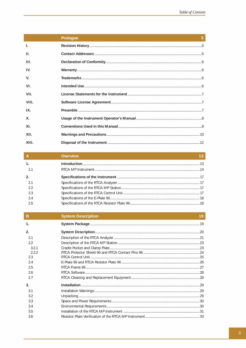
Table of Content
Prologue 5
I. Revision History .................................................................................................................................................5
II. Contact Addresses ...........................................................................................................................................5
III. Declaration of Conformity ............................................................................................................................6
IV. Warranty .................................................................................................................................................................6
V. Trademarks ...........................................................................................................................................................6
VI. Intended Use ........................................................................................................................................................6
VII. License Statements for the Instrument ................................................................................................7
VIII. Software License Agreement .....................................................................................................................7
IX. Preamble ................................................................................................................................................................7
X. Usage of the Instrument Operator’s Manual .....................................................................................8
XI. Conventions Used in this Manual ............................................................................................................8
XII. Warnings and Precautions ........................................................................................................................ 10
XIII. Disposal of the Instrument ....................................................................................................................... 12
A Overview 13
1. Introduction ....................................................................................................................................................... 13
1.1 RTCA MP Instrument........................................................................................................................................ 14
2. Specifi cations of the Instrument ........................................................................................................... 17
2.1 Specifi cations of the RTCA Analyzer .......................................................................................................... 172.2 Specifi cations of the RTCA MP Station ..................................................................................................... 172.3 Specifi cations of the RTCA Control Unit ................................................................................................... 172.4 Specifi cations of the E-Plate 96 ................................................................................................................... 182.5 Specifi cations of the RTCA Resistor Plate 96 .......................................................................................... 18
B System Description 19
1. System Package ............................................................................................................................................. 19
2. System Description ....................................................................................................................................... 20
2.1 Description of the RTCA Analyzer ............................................................................................................... 212.2 Description of the RTCA MP Station .......................................................................................................... 23
3.2.1 Cradle Pocket and Clamp Plate .................................................................................................................... 232.2.2 RTCA Protector Shield 96 and RTCA Contact Pins 96 ......................................................................... 24
2.3 RTCA Control Unit ............................................................................................................................................. 252.4 E-Plate 96 and RTCA Resistor Plate 96 ..................................................................................................... 262.5 RTCA Frame 96 ................................................................................................................................................... 272.6 RTCA Software .................................................................................................................................................... 282.7 RTCA Cleaning and Replacement Equipment ........................................................................................ 28
3. Installation ......................................................................................................................................................... 29
3.1 Installation Warnings ........................................................................................................................................ 293.2 Unpacking ............................................................................................................................................................ 293.3 Space and Power Requirements ..................................................................................................................303.4 Environmental Requirements ........................................................................................................................303.5 Installation of the RTCA MP Instrument ..................................................................................................313.6 Resistor Plate Verifi cation of the RTCA MP Instrument ...................................................................... 33
24050709 MP Instrument Operator's Manual.indb 324050709 MP Instrument Operator's Manual.indb 3 29.09.2009 14:07:4429.09.2009 14:07:44

4RTCA MP Instrument Operator’s Manual
Table of Content
C Operation 37
1. Introduction ....................................................................................................................................................... 37
2. Instrument Start-Up and Warm-Up ..................................................................................................... 37
3. Preparing and Starting a Run on the RTCA MP Instrument ..................................................38
3.1 Running a Quick Experiment ........................................................................................................................383.2 Important Tips for Using the RTCA MP Instrument ............................................................................ 45
D Maintenance and Care 48
1. General Maintenance ..................................................................................................................................48
2. Cleaning Instructions ...................................................................................................................................49
2.1 General Cleaning ...............................................................................................................................................492.2 Further Recommendations .............................................................................................................................49
3. Cleaning and Replacing the RTCA Contact Pins 96 ...................................................................50
4. Exchanging Fuses ..........................................................................................................................................54
E Appendix 56
1. Troubleshooting...............................................................................................................................................56
1.1 I started an experiment and there was an error message, “Cannot fi nd instrument!” What happened? ..........................................................................................561.2 I started an experiment. There was an error message, “ACK communication lost.” What happened? ........................................................................................ 571.3 I started an experiment and there was a sound and the error message, “No Station.” What happened? .....................................................................................................................581.4 How do I reinitialize the RTCA MP Instrument after a power failure?...........................................581.5 The Cell Index signal is signifi cantly lower than usual. Why? ..........................................................591.6 The Cell Index signal decreases with time, but there was no compound added. Why? ........601.7 The Cell Index signal is signifi cantly higher than usual. Why? .........................................................601.8 I did a background measurement. The RTCA Software indicated that many wells may have background problems. What should I do? ..........................................611.9 I placed an E-Plate 96 into a cradle of the RTCA MP Station. The Device Indicating LED did not turn orange. What should I do? ............................................621.10 I am contacting the local Roche representative or Roche Technical Support. What data fi les should be sent? .................................................................................................................62
2. Ordering Information ....................................................................................................................................63
24050709 MP Instrument Operator's Manual.indb 424050709 MP Instrument Operator's Manual.indb 4 29.09.2009 14:07:4429.09.2009 14:07:44

5Prologue
Prologue
I. Revision History
Version Revision Date
1.0 September 2008
2.0 March 2009
2.1 (editorial changes) November 2009
© Copyright 2009, Roche Diagnostics GmbH, ACEA Biosciences, Inc. All rights reserved. Information in this document is subject to change without notice. No part of this document may be reproduced or transmitted in any form or by any means, electronic or mechanical, for any purpose, without the express written permission of Roche Diagnostics GmbH.
Questions or comments regarding the contents of this manual can be directed to the address below or to your Roche representative.
Roche Diagnostics GmbHRoche Applied ScienceCustomer SupportNonnenwald 282377 Penzberg, Germany
Every effort has been made to ensure that all the information contained in the RTCA MP Instrument Operator’s Manual is correct at the time of printing.
However, Roche Diagnostics GmbH and ACEA Biosciences, Inc. reserve the right to make any changes necessary without notice as part of ongoing product development.
II. Contact Addresses
Manufacturer ACEA Biosciences, Inc.6779 Mesa Ridge Rd Ste 100San Diego, CA 92121USA
Distribution Roche Diagnostics GmbHSandhofer Straße 116D-68305 MannheimGermany
Distribution in USA Roche Diagnostics 9115 Hague Road PO Box 50457 Indianapolis, IN 46250 USA
Revision History
24050709 MP Instrument Operator's Manual.indb 524050709 MP Instrument Operator's Manual.indb 5 29.09.2009 14:07:4429.09.2009 14:07:44

6RTCA MP Instrument Operator’s Manual
III. Declaration of Conformity
The instrument meets the requirements laid down in Council Directive 2004/108/EC relating to “Electromagnetic Compatibility” and Council Directive 2006/95/EC relating to “Low Voltage Equipment”. The following standards were applied: IEC/EN 61326 (EMC) and IEC/EN 61010-1 (Safety).
UL 61010-1 Electrical Equipment for Measurement, Control and Laboratory Use; Part 1: General Requirements CAN/CSA-C22.2 No. 61010-1 (Second Edition) — Safety Requirements for Electrical Equipment for Measurement, Control and Laboratory Use; Part 1: General Requirements
IV. WarrantyInformation on warranty conditions are specifi ed in the sales contract. Contact your Roche representative for further information.
Any unauthorized modifi cation of the instrument invalidates the guarantee and service contract.
V. TrademarksXCELLIGENCE is a trademark of Roche.
E-PLATE and ACEA BIOSCIENCES are registered trademarks of ACEA Biosciences, Inc. in the US.
Other brands or product names are trademarks of their respective holders.
VI. Intended UseThe RTCA (Real-Time Cell Analyzer) MP (Multiple Plate) Instrument is intended for label-free, real-time, automated monitoring of cell status in a variety of cell-based assays, using proprietary microelectronic sensor technology developed by ACEA Biosciences. It can be used for both high throughput screening and research laboratory environments.
The RTCA MP Instrument is intended for life science research and must be used exclusively by laboratory professionals who are trained in laboratory techniques and have studied the instructions for use of this instrument. The RTCA MP Instrument is not intended for use in diagnostic procedures.
Declaration of Conformity
24050709 MP Instrument Operator's Manual.indb 624050709 MP Instrument Operator's Manual.indb 6 29.09.2009 14:07:4429.09.2009 14:07:44

7Prologue
VII. License Statements for the InstrumentThis RTCA MP Instrument is a real-time cell based assay system covered by US patent No.7,192,752, No. 7,459,303, No. 7,468,255, No. 7,470,533, No. 7,560,269, US patent applications 11,235,938, 11,286,882, 11,198,831, Chinese Patent No. ZL03822454.2, ZL2004 8 0040230.5, European patent applications 03748948.1, 03751801.6 and 04801001.1, and other patent applications owned by ACEA Biosciences, Inc.
VIII. Software License AgreementAn envelope containing all license and end user agreements is packaged with the RTCA Control Unit. It contains:
- RTCA Software End User License Agreement
- End User License Agreement for Microsoft Windows XP Pro for Embedded Systems
- End User License Agreement for Microsoft Offi ce Small Business 2007
- Microsoft Offi ce Small Business 2007 product key on a plastic card
- End User License Agreement for Symantec Antivirus Software
- End user License Agreement for Symantec Ghost Software
- GNU General Public License for Adobe PDF Creator
Please observe all statements made in these documents.
IX. PreambleThe RTCA MP Instrument Operator’s Manual must be used in conjunction with the corresponding RTCA Software Manual. Before setting up the RTCA MP Instrument, read this Operator’s Manual and the corresponding RTCA Software Manual thoroughly and completely. Failure to observe the instructions contained in this manual could be hazardous.
License Statements for the Instrument
24050709 MP Instrument Operator's Manual.indb 724050709 MP Instrument Operator's Manual.indb 7 29.09.2009 14:07:4429.09.2009 14:07:44
8RTCA MP Instrument Operator’s Manual
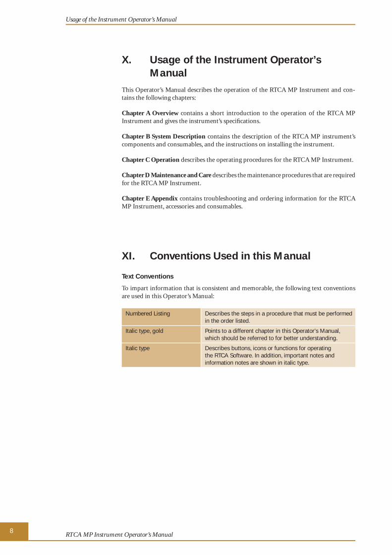
X. Usage of the Instrument Operator’s Manual
This Operator’s Manual describes the operation of the RTCA MP Instrument and con-tains the following chapters:
Chapter A Overview contains a short introduction to the operation of the RTCA MP Instrument and gives the instrument’s specifi cations.
Chapter B System Description contains the description of the RTCA MP instrument’s components and consumables, and the instructions on installing the instrument.
Chapter C Operation describes the operating procedures for the RTCA MP Instrument.
Chapter D Maintenance and Care describes the maintenance procedures that are required for the RTCA MP Instrument.
Chapter E Appendix contains troubleshooting and ordering information for the RTCA MP Instrument, accessories and consumables.
XI. Conventions Used in this Manual
Text Conventions
To impart information that is consistent and memorable, the following text conventions are used in this Operator’s Manual:
Numbered Listing Describes the steps in a procedure that must be performed in the order listed.
Italic type, gold Points to a different chapter in this Operator’s Manual, which should be referred to for better understanding.
Italic type Describes buttons, icons or functions for operating the RTCA Software. In addition, important notes and information notes are shown in italic type.
Usage of the Instrument Operator’s Manual
24050709 MP Instrument Operator's Manual.indb 824050709 MP Instrument Operator's Manual.indb 8 29.09.2009 14:07:4429.09.2009 14:07:44

9Prologue
Symbols
In this Operator’s Manual symbols are used as a visual signal to highlight important points.
Symbol Heading Description
WARNING This symbol is used to indicate that noncompliance with instructions or procedures could lead to physical injury or even death or could cause damage to the instrument.
BIOHAZARD This symbol indicates that certain precautions must be taken when working with potentially infectious sample material.
IMPORTANT NOTE Information critical to the success of the procedure or use of the product.
INFORMATION NOTE Additional information about the current topic or procedure.
��� Table continued on next page.
■ End of table.
The following symbols appear on the instrument:
Symbol Heading Description
AC Alternating Current
ON/OFF Power ON
Power OFF
GND Protective Earth Ground
FUSE Fuse: Refer to included safety statements
WEEE Electrical and electronic equipment marked with this symbol are covered by the European Directive WEEE.
The symbol denotes that the equipment must not be disposed off in the municipal waste system.
BIOHAZARD This symbol indicates that certain precautions must be taken when working with potentially infectious material.
COM COM Communications Port
EPS EPS E-Plate Station Port
Conventions Used in this Manual
24050709 MP Instrument Operator's Manual.indb 924050709 MP Instrument Operator's Manual.indb 9 29.09.2009 14:07:4429.09.2009 14:07:44

10RTCA MP Instrument Operator’s Manual
XII. Warnings and Precautions
Handling Requirements
Users of the RTCA MP Instrument must be trained and skilled personnel. It is essential that all personnel read carefully and observe the following safety information required for installation and operation of the RTCA MP Instrument. Please ensure that this safety information is accessible to every employee working with the RTCA MP Instrument.
� Follow all safety instructions printed on or attached to the instrument.
� Observe all general safety precautions applicable to electrical instruments.
� Do not access any electrical parts while the RTCA MP Instrument is connected to an electrical outlet.
� Never touch switches or power cords with wet hands.
� Do not open the housing of the RTCA MP Instrument.
� Never clean the instrument without turning the instrument power switch off and disconnecting the power cord.
� Only authorized service personnel are allowed to perform service operations or repairs required for this instrument.
� Do not open the clamp plate of the RTCA MP Station during measurement as this will cause an open circuit, leading to an error message from the RTCA Software.
For your own safety, please consider all biological material as potentially infectious. Handling and disposal of such material should be performed according to local safety guidelines. Spills should be immediately disinfected with an appropriate disinfectant solution to avoid spreading infection to, and contamination of, laboratory personnel or equipment. When working with potentially infectious material, always use protective gloves (powder-free).
� Please refer to the section on Maintenance and Care for instructions on cleaning the RTCA MP Instrument.
Warnings and Precautions
24050709 MP Instrument Operator's Manual.indb 1024050709 MP Instrument Operator's Manual.indb 10 29.09.2009 14:07:4429.09.2009 14:07:44

11Prologue
General Precautions
Microsoft Offi ce and Symantec Antivirus software have been tested and do not interfere with the RTCA Software. No other additional software may be installed on the RTCA Control Unit. If any additional software is installed on the RTCA Control Unit, it may interfere with RTCA Software, and could affect experimental results or control unit security.
Make sure that the main switch can be reached easily. Inappropriate location of the instrument can cause incorrect results and damage to the equipment parts. Follow the installation instructions carefully. Keep all potentially infl ammable or explosive material (for example, anesthetic gas) away from the instrument. Spraying liquid on electrical parts can cause a short circuit and result in a fi re.
Keep the cover closed while the instrument is connected to an electrical outlet and do not use sprays in the vicinity of the RTCA MP Instrument. During fi refi ghting operations, disconnect the power line of the RTCA MP Instrument.
Electrical Safety
The RTCA MP Instrument is designed in accordance with Protection Class I (IEC). The chassis/housing of the instrument is grounded to protection earth (PE) by means of a cord. For protection against electrical shock hazards, the instrument must be directly connected to an approved power source such as a three-wire grounded receptacle for the 110 V or 230 V line. Do not use an ungrounded receptacle; have a qualifi ed electrician replace the ungrounded receptacle with a properly (PE) grounded receptacle in accordance with the local electrical code. Do not use an extension. Any break in the electrical ground path, whether inside or outside the instrument, could be hazardous. Under no circumstances should the user attempt to modify or deliberately defeat the safety features of this instrument. If the power cord becomes cracked, frayed, broken, or otherwise damaged, replace it immediately with the equivalent part from Roche Diagnostics.
Warnings and Precautions
24050709 MP Instrument Operator's Manual.indb 1124050709 MP Instrument Operator's Manual.indb 11 29.09.2009 14:07:4429.09.2009 14:07:44

12RTCA MP Instrument Operator’s Manual
XIII. Disposal of the InstrumentAll electrical and electronic products should be disposed of separately from the municipal waste system. Proper disposal of your old appliance prevents potential negative conse-quences for the environment and human health.
The instrument must be treated as biologically contaminated hazardous waste. Final disposal must be accomplished in a way that does not endanger waste handlers. As a rule, such equipment must be sterile before it is passed on for fi nal disposal.
For more information contact your local Roche Support personnel.
The instrument should also be decontaminated prior to shipping it for outside service or repairs.
Components of your Control Unit such as the computer, monitor, keyboard, etc. which are marked with the crossed-out wheeled bin symbol are covered by the European Directive 2002/96/EC (WEEE).
These items must be disposed of via designated collection facilities appointed by government or local authorities.
For more information about disposal of your old product, please contact your city offi ce, waste disposal service or your local Roche Support personnel.
It is left to the discretion of the responsible laboratory organization to determine whether the RTCA Control Unit and RTCA Analyzer are contaminated or not. If con-taminated, treat in the same way as the RTCA MP Station .
Disposal of the Instrument
24050709 MP Instrument Operator's Manual.indb 1224050709 MP Instrument Operator's Manual.indb 12 29.09.2009 14:07:4429.09.2009 14:07:44

13Overview
AAA Overview
1. IntroductionRoche Applied Science and ACEA Biosciences have jointly developed the proprietary microelectronic sensor technologies of the RTCA (Real-Time Cell Analyzer) Instrument for monitoring adherent cells.
Over 95% of current biological assays are based on optical detection (e.g., fl uorescent and optical detection in a fl uorescence plate reader, optical microscopy, FACS analyzer, fl uorescence scanner). In contrast, the new RTCA MP Instrument developed by ACEA Biosciences is based on electronic detection of biological assay processes, thereby integrat-ing molecular and cell biology with microelectronics.
The presence, absence, or change in properties of cells or molecules affects the passage of electrons and ions on sensor surfaces. Measuring the electronic properties of sensor surfaces provides important information about the biological status of cells (or proteins) present on the sensors. When changes occur in the biological status of cells or proteins, the RTCA MP Instrument automatically measures the corresponding changes in the elec-tronic properties of the sensors near the cells. These analog electronic readout signals are then converted to digital signals for processing and analysis. The major advantages of the RTCA MP Instrument for biological assays over conventional approaches include:
� Label-free detection
� Non-invasive, real-time monitoring
� Automated measurement
� Easy set-up, operation and control
� High information content
� High sensitivity and accuracy
� Broad range of applications
This new microelectronic sensing system represents one of the fi rst integrations of elec-tronic methodology and cell-based assays.
Introduction
24050709 MP Instrument Operator's Manual.indb 1324050709 MP Instrument Operator's Manual.indb 13 29.09.2009 14:07:4429.09.2009 14:07:44

14RTCA MP Instrument Operator’s Manual
AA1.1 RTCA MP InstrumentThe new RTCA MP (Multiple Plate) Instrument is a proprietary microelectronic biosen-sor system for cell-based assays. The core of the system is the microelectronic cell sensor arrays that are integrated into the bottom of 96-well plates (E-Plate 96). Measuring the electronic impedance of these sensor electrodes allows changes in cells on the electrodes to be detected and monitored. Cell viability, cell number, cell morphology, and degree of adhesion all affect electrode impedance.
The RTCA MP Instrument offers six positions for E-Plates 96, thereby allowing to be utilized by up to six different users simultaneously.
Impedance measured between electrodes in an individual well depends on electrode geometry, ionic concentration in the well and whether cells are attached to the electrodes. In the absence of cells, electrode impedance depends mainly on the ionic environment both at the electrode/solution interface and in the bulk solution. In the presence of cells, cells attached to the electrode sensor surfaces will act as insulators and thereby alter the local ionic environment at the electrode/solution interface, leading to an increase in impedance. Thus, the more the cells there are on the electrodes, the larger the change in electrode impedance (Figure 1).
Furthermore, the impedance change also depends on the extent to which cells attach to the electrodes (Figure 1). For example, cell spreading resulting in a large cell/electrode contact area leads to a large change in impedance.
Figure 1: Schematic illustration of the impedance measurement principle.
Introduction
RTCA MP Instrument
24050709 MP Instrument Operator's Manual.indb 1424050709 MP Instrument Operator's Manual.indb 14 29.09.2009 14:07:4429.09.2009 14:07:44

15Overview
AAIntroduction
RTCA MP Instrument
Derivation of the Cell Index (CI)
A parameter, called Cell Index (CI), is used to measure the relative change in electrical impedance that represents cell status. The Cell Index is a relative and dimensionless value since it is derived by dividing the impedance change by a background value. When there are no cells present in the medium, the sensor’s electronic properties will not be affected and the impedance will be small, as shown in Figure 1 when Z = Z0.
When there are more cells on the electrodes, the impedance will be larger. The CI calculation is based on the following formula: CI = (Zi – Z0)/15 �, where Zi is the impedance at an individual time point during the experiment, and Z0 is the impedance at the start of the experiment. Thus Cell Index is a self-calibrated value derived from the ratio of impedances. For more detailed information on how to derive the Cell Index, please refer to the Monitor the Experiment section in the RTCA Software Manual. Briefl y, here are some features of the CI:
� When cells are not present or are not well-adhered on the electrodes, then the CI is about zero.
� Under the same physiological conditions, when more cells are attached on the electrodes, then the CI values are higher. In this case, CI is a quantitative measure of the cell number present in a well.
� Additionally, change in a cell status, such as cell morphology, cell adhesion or cell viability can a lead to a change in CI.
The measurement of impedance is non-invasive to the cells, and only a very weak electri-cal signal is applied to the sensor electrodes. The AC excitation voltage level is in the mV range and the resulting current is in the µA range so that individual wells in a plate can be interrogated repeatedly over a wide interval range throughout the experiment. Chemical compounds or other reagents can be added at any time and monitored continuously for hours or days. Unlike “end point” assays, the system allows an investigator to monitor the entire course of the experiment in real time without interruption.
The RTCA MP Instrument contains the following main components:
RTCA Control Unit
RTCA Analyzer
RTCA MP Station
E-Plate 96
Figure 2: The RTCA MP Instrument with the main components: RTCA Analyzer, RTCA MP Station, E-Plate 96 and RTCA Control Unit. The RTCA MP Station offers six positions for E-Plates 96, thereby allowing to be utilized by up to six different users simultaneously.
24050709 MP Instrument Operator's Manual.indb 1524050709 MP Instrument Operator's Manual.indb 15 29.09.2009 14:07:4729.09.2009 14:07:47

16RTCA MP Instrument Operator’s Manual
AACells are introduced into the wells of the E-Plate 96, making contact with, and attach-ing to the sensor electrode surfaces. The electronic properties of the sensor surfaces are monitored through the RTCA MP Station, which can be placed inside a tissue culture incubator, and the RTCA Analyzer. This monitoring is controlled by the RTCA Software on the RTCA Control Unit, to provide real-time, quantitative information about the bio-logical status of the cells, including cell number, viability, morphology and cytoskeletal dynamics.
The RTCA Instrument can be used for a wide variety of cell-based assay applications, including:
� Cell adhesion and spreading
� Cell proliferation and differentiation
� Compound-mediated cytotoxicity/Apoptosis
� Cell-mediated cytotoxicity
� Receptor-mediated signaling
� Quality control of cells
� Virus-mediated cytopathogenicity
The System is highly quantitative, with excellent accuracy, precision, and ease of use. The RTCA Software can be used for simplifi ed experimental design and set-up; it will then direct the instrument to perform the experiment and provide fully automated data acquisition, data analysis, and data presentation.
Introduction
RTCA MP Instrument
24050709 MP Instrument Operator's Manual.indb 1624050709 MP Instrument Operator's Manual.indb 16 29.09.2009 14:07:5029.09.2009 14:07:50

17Overview
AA2. Specifi cations of the Instrument
The RTCA MP Instrument must be operated at an altitude/pressure of 0–2000 m above sea level, 80–106 kPa.
2.1 Specifi cations of the RTCA Analyzer
� Dimensions: 40.0 cm × 40.0 cm × 9.0 cm (W × D × H)
� Weight: 7.4 kg
� Electrical Input: 100 – 240 VAC, 50 – 60 Hz, 25 W max
� Output test signal: 22 mV rms ± 20% with max. 5 mV DC offset at 10, 25 and 50 kHz
� Impedance Measurement Accuracy: ± (1.5% + 1 �)
� Impedance Measurement Repeatability: 0.8%
� Impedance Dynamic Range: 10 � to 5 k�
� Communication: RS232 Serial communications at a baud rate of 57600 bits/second
� Environment: temperature, +15 °C to +32°C; relative humidity, 80% max. up to +32°C, without condensation
2.2 Specifi cations of the RTCA MP Station
� Dimension: 42.0 cm × 43.0 cm × 18.0 cm (W × D × H)
� Weight: 18.0 kg
� Electrical Input: +12 V, +5 V, -5 V; 10 W max
� Electronic Switch Resistance: 2 – 5 �
� Electrical Interface: Handling six E-Plate 96
� Communication: RS232 Serial communications at a baud rate of 57,600 bits/second
� Environment: temperature, + 15 °C to + 40 °C; relative humidity, 98% maximum without condensation
2.3 Specifi cations of the RTCA Control Unit
� � 120 GB Hard disk drive
� � 2 GB RAM
� � 256 MB Graphics device
The Windows® Operating System (OS) delivered with the RTCA Control Unit is modifi ed to ensure optimal performance and operation with the RTCA MP Instrument. These modifi cations restrict certain network capabilities such as sharing folders and printers to the network. However, to facilitate the transport of data to and from the RTCA Control Unit, the following network features remain enabled:
� Mount Network Drives for data exchange
� FTP (File Transfer Protocol)
� Automatically update Virus Defi nition Files
Specifi cations of the Instrument
Specifi cations of the RTCA Analyzer
24050709 MP Instrument Operator's Manual.indb 1724050709 MP Instrument Operator's Manual.indb 17 29.09.2009 14:07:5029.09.2009 14:07:50

18RTCA MP Instrument Operator’s Manual
AA2.4 Specifi cations of the E-Plate 96
� Footprint: complying with ANSI/SBS 1-2004 requirements
� Dimension: 12.77 cm × 8.55 cm × 1.75 cm (W × D × H) (with plate cover)
� Spacing: The spacing of the wells is 9 mm center-to-center, per the ANSI/SBS 4-2004 standard for 96-well titer plates
� Volume: 243 µl ± 5 µl
� Bottom Diameter: 5.0 mm ± 0.05 mm
� Electrical Interface: Interface with RTCA MP Station
� Sensor Impedance: 17 �± 5 � at 10 kHz, when measured with a 1× PBS Solution
� Material: Biocompatible surfaces
� UV irradiated
� Environment: temperature, + 15 °C to + 40 °C; relative humidity, 98% maximum without condensation
2.5 Specifi cations of the RTCA Resistor Plate 96
� Dimension: 12.77 cm × 8.55 cm × 1.75 cm (W × D × H) (with plate cover)
� Electrical Interface: Interface with RTCA MP Station
� Environment: temperature, + 15 °C to + 40 °C; relative humidity, 98% maximum without condensation
� Resistor values: 37.4, 64.9, 91.0, 115.0 �, ± 0.5%
The resistor values specifi ed for the RTCA Resistor Plate 96 are different variables than raw scan data acquired during resistor plate verifi cation. Therefore, they are not com-parable to acceptance values listed in chapter Resistor Plate Verifi cation of the RTCA MP Instrument.
Specifi cations of the Instrument
Specifi cations of the E-Plate 96
24050709 MP Instrument Operator's Manual.indb 1824050709 MP Instrument Operator's Manual.indb 18 29.09.2009 14:07:5029.09.2009 14:07:50

System Description
BB
19
B System Description
1. System PackageThe table below lists all the components required for the RTCA MP Instrument. Check for completeness and inspect packaging prior to installation.
The original shipping boxes must be transferred unopened to the installation site. On delivery, carefully inspect the boxes. It is essential that you report any suspected damage immediately to Roche Diagnostics and to the shipping agent before accepting the product.
Use only the original packaging for transportation or relocation of the equipment.
Quantity Component
1
1
1
RTCA Analyzer
Power Cables for RTCA Analyzer
Cable Connection between RTCA Analyzer and RTCA Control Unit (serial cable)
1
1
6
6
3 × 10
1
1
1
1
RTCA MP Station
Cable Connection between RTCA Analyzer and RTCA MP Station (fl at, shielded cable)
RTCA Protector Shield 96
RTCA Resistor Plate 96
RTCA Contact Pins 96
RTCA Contact Pin Replacement Tool
RTCA Cleaning Kit, including Brush and Dust Blower
RTCA Contact Pin Insertion Tool
Tweezers
1
1
1
1
RTCA Control Unit
Mobile Port Replicator for RTCA Control Unit
RTCA Software Package, including: � RTCA MP Instrument Operator’s Manual � RTCA MP Instrument Short Guide � RTCA Software Manual � RTCA Software CD
Power Adapter and Cables for RTCA Control Unit
System Package
24050709 MP Instrument Operator's Manual.indb 1924050709 MP Instrument Operator's Manual.indb 19 29.09.2009 14:07:5029.09.2009 14:07:50

RTCA MP Instrument Operator’s Manual
BB
20
2. System DescriptionThe RTCA MP Instrument is designed for label-free cell based assays. The core of the instrument is a microelectronic biosensor array incorporated into each well of standard-sized 96-well microplate devices. This permits the RTCA MP Instrument to measure the activity of living cells in real-time without any labels or reporters. Any number of cellular parameters such as attachment, spreading, growth, death, and even specifi c morphologi-cal changes can be simply and reliably detected with the RTCA MP Instrument.
The RTCA MP Instrument includes the following main components:
� RTCA Analyzer
� RTCA MP Station
� RTCA Control Unit with RTCA Software preinstalled
� E-Plate 96
RTCA Control Unit withRTCA Software
E-Plate 96
RTCA Analyzer RTCA MP Station
Figure 3: The RTCA MP Instrument.
In addition, operation of the RTCA MP Instrument requires several accessories:
� RTCA Protector Shield 96
� RTCA Resistor Plate 96
� RTCA Contact Pins 96
� RTCA Cleaning Kit (Brush + Dust Blower)
� RTCA Contact Pin Replacement Tool, Insertion Tool and Tweezers
� Mobile Port Replicator for RTCA Control Unit
� Connective and Power Cables
System Description
24050709 MP Instrument Operator's Manual.indb 2024050709 MP Instrument Operator's Manual.indb 20 29.09.2009 14:07:5029.09.2009 14:07:50

System Description
BB
21
System Description
Description of the RTCA Analyzer
2.1 Description of the RTCA AnalyzerThe RTCA Analyzer is an electronic analyzer that can, under the control of RTCA Soft-ware, conduct electronic impedance measurement of sensor electrodes at various signal frequencies. The RTCA Analyzer is capable of computer-controlled signal generation, processing and analysis, automatic frequency scanning and rapid measurement.
The average measurement speed is approx. 15 seconds for one E-Plate 96 and 90 (6×15) seconds for six E-Plates 96, or approx. 150 ms for each well. During an experiment, the RTCA Analyzer will conduct the measurement of up to six E-Plates 96 in the “fi rst come, fi rst served” order, depending on the measurement schedule set up in the RTCA Software.
Figure 4: The RTCA Analyzer.
Interfaces and indicators:
The RTCA Analyzer communicates with the RTCA Control Unit through a standard 9-pin RS-232 serial port designated as COM. Signals and communications to the RTCA MP Station are through the EPS port, both of these ports are located at the rear panel of the RTCA Analyzer.
RS232 Serial Port EPS Port
RearPanel
Figure 5: The RTCA Analyzer rear panel.
24050709 MP Instrument Operator's Manual.indb 2124050709 MP Instrument Operator's Manual.indb 21 29.09.2009 14:07:5529.09.2009 14:07:55

RTCA MP Instrument Operator’s Manual
BB
22
Keypad and indicators:
� Power LED, solid green if power is on.
� Communication LED, blinks if communication between RTCA MP Station and RTCA Analyzer is occurring.
� Status LED, indicates system status. Solid green if power is on, blinks green if measure-ment is in progress, also blinks green once if self-test is passed. Red indicates a system error, such as failed self-test, no station or communication error.
� Self-test button, the status LED will fl ash green once if test is passed. It is RED if self-test fails.
FrontPanel
Power Communication Status Self-test
Figure 6: The RTCA Analyzer front panel.
RTCA Analyzer Cat. No. 05 228 972 001
System Description
Description of the RTCA Analyzer
24050709 MP Instrument Operator's Manual.indb 2224050709 MP Instrument Operator's Manual.indb 22 29.09.2009 14:07:5729.09.2009 14:07:57
System Description
BB
23
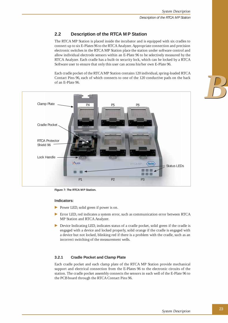
2.2 Description of the RTCA MP StationThe RTCA MP Station is placed inside the incubator and is equipped with six cradles to connect up to six E-Plates 96 to the RTCA Analyzer. Appropriate connection and precision electronic switches in the RTCA MP Station place the station under software control and allow individual electrode sensors within an E-Plate 96 to be selectively measured by the RTCA Analyzer. Each cradle has a built-in security lock, which can be locked by a RTCA Software user to ensure that only this user can access his/her own E-Plate 96.
Each cradle pocket of the RTCA MP Station contains 120 individual, spring-loaded RTCA Contact Pins 96, each of which connects to one of the 120 conductive pads on the back of an E-Plate 96.
P4
P1
P5
P2
P6
P3
Status LEDs
Clamp Plate
Cradle Pocket
Lock Handle
RTCA Protector Shield 96
Figure 7: The RTCA MP Station.
Indicators:
� Power LED, solid green if power is on.
� Error LED, red indicates a system error, such as communication error between RTCA MP Station and RTCA Analyzer.
� Device Indicating LED, indicates status of a cradle pocket, solid green if the cradle is engaged with a device and locked properly, solid orange if the cradle is engaged with a device but not locked, blinking red if there is a problem with the cradle, such as an incorrect switching of the measurement wells.
3.2.1 Cradle Pocket and Clamp Plate
Each cradle pocket and each clamp plate of the RTCA MP Station provide mechanical support and electrical connection from the E-Plates 96 to the electronic circuits of the station. The cradle pocket assembly connects the sensors in each well of the E-Plate 96 to the PCB board through the RTCA Contact Pins 96.
System Description
Description of the RTCA MP Station
24050709 MP Instrument Operator's Manual.indb 2324050709 MP Instrument Operator's Manual.indb 23 29.09.2009 14:08:0029.09.2009 14:08:00

RTCA MP Instrument Operator’s Manual
BB
24
2.2.2 RTCA Protector Shield 96 and RTCA Contact Pins 96
In electronic equipment, a Contact Pin is a device that provides a frequent but temporary electrical connection. It is widely used in ATEs (automatic test equipment) for circuit test-ing. In the RTCA MP Station, the RTCA Contact Pins 96 are very important for ensuring electrical connection between the sensor and the control board.
Since it is very important to keep the RTCA Contact Pins 96 from being bent or damaged, an RTCA Protector Shield 96 ensures that the pins are not damaged during insertion or removal of the E-Plate 96.
To ensure good electrical connection, the RTCA Contact Pins 96 need to be cleaned regularly. Thus, it is recommended to clean the RTCA Contact Pins 96 every three months. More frequent cleaning may also be necessary, such as when certain positions show larger contact resistance.
The RTCA Contact Pins can also be replaced. Please refer to the Maintenance and Care section of this manual for instructions on the cleaning and replacement of RTCA Contact Pins 96.
RTCA Protector Shield 96 RTCA Contact Pins 96
Figure 8: RTCA Contact Pins 96 and RTCA Protector Shield 96.
RTCA MP Station Cat. No. 05 331 625 001
System Description
Description of the RTCA MP Station
24050709 MP Instrument Operator's Manual.indb 2424050709 MP Instrument Operator's Manual.indb 24 29.09.2009 14:08:0229.09.2009 14:08:02

System Description
BB
25
2.3 RTCA Control UnitThe RTCA Control Unit consists of a laptop computer with a mobile port replicator device connected to it (Figure 9). The operating system and all software tools necessary to run the RTCA MP Instrument are already pre-installed.
Figure 9: The RTCA Control Unit (left) and Mobile Port replicator (right).
RTCA Control Unit 1.1 Cat. No. 05 454 417 001
System Description
RTCA Control Unit
24050709 MP Instrument Operator's Manual.indb 2524050709 MP Instrument Operator's Manual.indb 25 29.09.2009 14:08:0329.09.2009 14:08:03

RTCA MP Instrument Operator’s Manual
BB
26
2.4 E-Plate 96 and RTCA Resistor Plate 96E-Plates 96 are single use, disposable devices used for performing cell-based assays on the RTCA MP Instrument. The E-Plate 96 is similar to commonly used 96x well micro-titer plates. Each well of the 96 wells on the E-Plates 96 has incorporated sensor electrode arrays so that cells inside each well can be monitored and assayed.
The plate lid is designed to ensure low evaporation. The bottom diameter of each well is 5.0 mm ± 0.05 mm, with a total volume of 243 µl ± 5 µl. Approx. 80% of the bottom area of each well is covered by the electrodes. The plate is designed to be used at temperatures between +15°C to +40°C and at relative humidities up to 98% maximum without con-densation.
Figure 10: The E-Plate 96.
The RTCA Resistor Plate 96 is used with the RTCA MP Instrument for system verifi cation purposes (see section on Resistor Plate Verifi cation of the RTCA MP Instrument). The RTCA Resistor Plate 96 is the same size as the E-Plate 96. However, instead of a microsen-sor array, each well of the resistor plate contains an array of resistors.
To verify system functionality, the RTCA Resistor Plate 96 is placed on the RTCA MP Station. The resistor plate will produce resistance values that approximate those of an E-Plate 96 containing only cell media in each well.
RTCA Resistor Plates 96 are not instrument- or cradle unit-specifi c. Each RTCA Re-sistor Plates 96 can be used to perform Resistor Plate Verifi cation on each RTCA MP Station and all corresponding cradle units.
Figure 11: The RTCA Resistor Plate 96.
System Description
E-Plate 96 and RTCA Resistor Plate 96
24050709 MP Instrument Operator's Manual.indb 2624050709 MP Instrument Operator's Manual.indb 26 29.09.2009 14:08:0629.09.2009 14:08:06

System Description
BB
27
2.5 RTCA Frame 96For experiments in which an extremely short reaction time is expected between the addition of a substance and the reaction of the cells, it would be highly desirable to be able to add compounds directly into the wells without removing the E-Plate 96 from the RTCA MP Station. For such an experimental set-up, the RTCA Frame 96 can be used in place of the usual lid of the E-Plate 96.
With the RTCA Frame 96 in place, you can directly pipette into the wells while the E-Plate 96 is locked in the RTCA MP Station.
RTCA Frame 96 is an optional accessory for the RTCA MP Instrument. Please contact a local Roche representative if you need it in your application.
Figure 12: The RTCA Frame 96.
RTCA Protector Shield 96 Cat. No. 05 288 967 001
RTCA Resistor Plate 96 Cat. No. 05 232 350 001
RTCA Frame 96 Cat. No. 05 232 392 001
E-Plate 966 Units Cat. No. 05 232 368 001
6 × 6 Units Cat. No. 05 232 376 001
RTCA Contact Pins 96 (20 Units) Cat. No. 05 232 384 001
System Description
RTCA Frame 96
24050709 MP Instrument Operator's Manual.indb 2724050709 MP Instrument Operator's Manual.indb 27 29.09.2009 14:08:1429.09.2009 14:08:14

RTCA MP Instrument Operator’s Manual
BB
28
2.6 RTCA SoftwareThe RTCA Software provides unparalleled instrument control, permitting fl exible experi-ment set-ups, data acquisition, and data analysis. All instrument and experiment controls are embedded in the RTCA Software to simplify instrument set-up and operation. The Software is used with the RTCA Analyzer and a single RTCA MP Station.
For a comprehensive description of the RTCA Software please refer to the RTCA Soft-ware Manual.
RTCA Software Package 1.2 Cat. No. 05 454 433 001
2.7 RTCA Cleaning and Replacement Equipment
RTCA Contact Pin Replacement and Insertion Tools
The RTCA Contact Pin Replacement and Insertion Tools are used to remove defective Pins from the RTCA MP Station and to insert new Pins. Pins can be safely handled using tweezers and these tools.
Figure 13: The RTCA Contact Pin Replacement Tool (upper part) and RTCA Contact Pin Insertion Tool (lower part).
RTCA Cleaning Kit
The RTCA Cleaning Kit includes a fi ber-free brush to clean the RTCA Contact Pins 96 and a dust blower to remove dirt particles from the RTCA MP Station or the RTCA Contact Pins 96.
Figure 14: The RTCA Cleaning Kit.
System Description
RTCA Software
24050709 MP Instrument Operator's Manual.indb 2824050709 MP Instrument Operator's Manual.indb 28 29.09.2009 14:08:1729.09.2009 14:08:17

System Description
BB
29
3. Installation
3.1 Installation Warnings Always make sure that the power switch on the RTCA Analyzer is in the OFF position,
and remove the power cord from the back of the instrument before installing or relocating the instrument.
Do not operate the instrument in an environment where potentially damaging liquids or gases are present.
Do NOT put the RTCA Control Unit and RTCA Analyzer in the incubator!
Use the supplied cord to connect the RTCA Analyzer to a grounded AC power line. This is not only for safety purposes, but also to reduce background noise in the RTCA MP Instrument. A stand-alone RTCA MP Instrument can work with a two-pronged AC power source, but in more complicated electrical environments, it is much better to use a well-grounded power socket. Otherwise there may be a risk of electrical shock, and/or the performance of the RTCA MP Instrument may be affected.
After installing an RTCA MP Station in an incubator, allow at least TWO hours before turning on or operating the system. This allows the Station to equilibrate with the incubator environment and reduces the risk of condensation-related problems.
Do not touch or loosen any screws or parts other than those specifi cally designated in the instructions. Doing so might affect instrument performance and void the instrument warranty.
3.2 Unpacking The RTCA Analyzer and RTCA MP Station are packed in a specially designed box.
Retain the box and packing materials. If the system needs to be returned for repair, it should be always transported in the packaging provided. It is essential that you report any suspected damage immediately to Roche Diagnostics and to the shipping agent before accepting the product.
The RTCA Analyzer and RTCA MP Station weigh approximately 7.4 kg and 18 kg, respectively. Lift them carefully, taking proper precautions to avoid injury.
After examining the box, place it on a fl at surface in the upright position. Open the top of the box and lift the RTCA Analyzer and RTCA MP Station, along with their packing materials, up and out of the shipping box. Remove the packing materials from the ends of the instrument and set the instrument down carefully.
Installation
Installation Warnings
24050709 MP Instrument Operator's Manual.indb 2924050709 MP Instrument Operator's Manual.indb 29 29.09.2009 14:08:2029.09.2009 14:08:20

RTCA MP Instrument Operator’s Manual
BB
30
3.3 Space and Power RequirementsThe RTCA MP Instrument is a low-power consumption system with universal power adaptability. The total power consumption of the RTCA Analyzer and RTCA MP Station is generally less than 15 Watts.
The RTCA Analyzer must be placed in a location that allows easy access to the rear panel On/Off Power Switch.
Do not place anything within 10 cm of the side ventilation ports of the RTCA Analyzer. Failure to observe this instruction may cause the equipment to overheat and increase the risk of fi re.
To facilitate easy installation and access to the RTCA MP Station, the recommended space requirement inside the incubator is 45.0 cm × 46.0 cm × 30.0 cm (W × D × H).
3.4 Environmental RequirementsThe RTCA Analyzer should be used in a standard laboratory environment. The RTCA MP Station should be used either in a tissue/cell culturing incubator that reaches 98% maximum humidity without condensation, or in a standard laboratory environment. Failure to follow these environmental requirements may reduce the operating life or cause damage to the instruments.
Do not place the RTCA Analyzer on top of a cell culture incubator.
Please do not install the RTCA MP Instrument in the immediate vicinity of other laboratory devices that may infl uence the highly sensitive electronic readout of the RTCA MP Instrument (e.g., ultracentrifuges, autoclaves).
Installation
Space and Power Requirements
24050709 MP Instrument Operator's Manual.indb 3024050709 MP Instrument Operator's Manual.indb 30 29.09.2009 14:08:2029.09.2009 14:08:20

System Description
BB
31
3.5 Installation of the RTCA MP Instrument This chapter describes the installation of the RTCA MP Instrument. A schematic diagram showing how to connect each component is provided in Figure 15.
CO2 Incubator
RTCA MP Station
100-240V AC50-60 Hz
RTCA Analyzer
To RTCA Control Unit
Figure 15: RTCA MP Instrument installation diagram.
Remove instruments from boxes
1 Remove RTCA Analyzer from the box.
2 Remove RTCA MP Station from the box.
3 Remove RTCA Control Unit and RTCA Software Package from the box.The Mobile Port Replicator is already connected to the bottom of the RTCA Control Unit.
Connect the RTCA Analyzer to the RTCA Control Unit
4 Locate the serial cable with two female connector ends (9-pin). Plug one end of the cable into the COM port of the Mobile Port Replicator and attach the other end of the cable to the COM port on the back of the RTCA Analyzer.
���
Installation
Installation of the RTCA MP Instrument
24050709 MP Instrument Operator's Manual.indb 3124050709 MP Instrument Operator's Manual.indb 31 29.09.2009 14:08:2029.09.2009 14:08:20

RTCA MP Instrument Operator’s Manual
BB
32
Place the RTCA MP Station into an incubator
5 Wipe the RTCA MP Station with tissue paper or a soft cloth that has been slightly wetted with 80% alcohol or another sterilizing agent.
Avoid spraying any sterilizing agent directly on the RTCA MP Station , except Contact Pin cleaning (see Cleaning and Exchanging the RTCA Contact Pins 96)!
Ideally, before placing the RTCA MP Station inside an incubator, it is recommended to set up the RTCA MP Instrument outside the incubator using a procedure similar to that being described here in section 3.5, and to perform a Resistor Plate Verifi cation as described in section 3.6.
6 Plug the 15-pin fl at ribbon cable into the back of the RTCA MP Station, tighten the two screws on the cable, then place the RTCA MP Station in the incubator. Run the fl at ribbon cable from the RTCA MP Station to the outside of the incubator, making sure that the incubator door still closes.
The RTCA MP Station weighs approximately 18 kg. Be careful when placing the RTCA MP Station inside the incubator, to avoid injury and damage to the instrument.
Connect the RTCA MP Station to the RTCA Analyzer
7 Insert the female connector at the end of the ribbon cable into the EPS port on the rear panel of the RTCA Analyzer.
To avoid condensation it is important to wait for at least TWO hours (after placing the RTCA MP Station inside the incubator) before running any experiments or turning on the RTCA Analyzer.
Attach the power cord to RTCA Analyzer and RTCA Control Unit
8 Attach the DC power plug of the AC adaptor (with attached power cord) to the RTCA Control Unit and connect the power cord to an AC outlet.
Do NOT turn on the RTCA Control Unit.
9 Attach the power cord to the RTCA Analyzer and plug it into an AC outlet.
Do NOT turn on the RTCA Analyzer.
10 Wait for two hours to let the RTCA MP Station equilibrate without condensation.
11 Turn on the RTCA Control Unit.
12 Turn on the RTCA Analyzer using the power switch located at the back of the Analyzer.
■
The LED on the front panel of the RTCA Analyzer should be green.
The RTCA Analyzer and RTCA MP Station are ready to run an assay.
The RTCA Analyzer is pre-programmed and ready to communicate with the RTCA Software.
There is one button on the front panel of the RTCA Analyzer, which is used to perform a self-test of the instrument. An LED will turn red if the RTCA Analyzer fails the self-test. In this case, please contact your local Roche representative.
Installation
Installation of the RTCA MP Instrument
24050709 MP Instrument Operator's Manual.indb 3224050709 MP Instrument Operator's Manual.indb 32 29.09.2009 14:08:2129.09.2009 14:08:21

System Description
BB
33
3.6 Resistor Plate Verifi cation of the RTCA MP InstrumentResistor Plate Verifi cation is a very important step for verifying the installation and function of the RTCA MP Instrument. The verifi cation process can be done outside the incubator at room temperature. Ideally, Resistor Plate Verifi cation should be performed both before and after the RTCA MP Station is put in an incubator. This ensures that the installation is correct, and that no condensation is affecting the RTCA MP Station after it is placed inside the incubator.
While a TWO hour equilibration is needed when the RTCA MP Station is fi rst put into an incubator, resistor plate verifi cation outside the incubator does not require this waiting period.
Start the RTCA Software
1 Having connected the cables and installed the system correctly, start the RTCA Soft-ware by double-clicking the RTCA Software icon on the desktop. If the program is already open, close it and then reopen it.
2 Click the Plate Window button to show the P1 Plate window. Set up the following experimental pages: Exp Notes, Layout (To turn on all the wells, right click on the Layout page, select all wells, then click Apply button; Figure 16.), and Schedule Pages (Click Add a Step button , set 10 sweeps with an interval of 30 sec; Figure 17).
For more information about setup, data format and storage, please refer to the RTCA Software Manual.
Figure 16: Setup of the Layout page for Resistor Plate Verifi cation.
Figure 17: Setup of the Schedule page for Resistor Plate Verifi cation.
���
Installation
Resistor Plate Verifi cation of the RTCA MP Instrument
24050709 MP Instrument Operator's Manual.indb 3324050709 MP Instrument Operator's Manual.indb 33 29.09.2009 14:08:2129.09.2009 14:08:21

RTCA MP Instrument Operator’s Manual
BB
34
3 Repeat the operations in Step 2 for the remaining P2, P3, P4, P5, and P6 Plate Windows.
Place the RTCA Resistor Plate 96 in the RTCA MP Station
4 Lift the P1 clamp plate of the MP Station. Insert the RTCA Protector Shield 96 into the P1 cradle pocket as shown in Figure 18. Repeat this operation for P2, P3, P4, P5, and P6.
The RTCA Protector Shield 96 protects the RTCA Contact Pins 96, when E-Plates 96 are inserted into or removed from the RTCA MP Station.
P1
P4
P2
P5
P3
P6
Figure 18: Insert the RTCA Protector Shield 96 in P1 cradle pocket of the RTCA MP Station.
5 While lifting the P1 clamp plate of the RTCA MP Station with one hand, insert one RTCA Resistor Plate 96 (with plate cover) in the P1 cradle pocket of the RTCA MP Station (Figure 19). Ensure that the angled corners are inserted fi rst and that the plate is fully inside the cradle pocket.
Figure 19: Insert the resistor plate and lock the clamp plate in position.
���
Installation
Resistor Plate Verifi cation of the RTCA MP Instrument
24050709 MP Instrument Operator's Manual.indb 3424050709 MP Instrument Operator's Manual.indb 34 29.09.2009 14:08:2229.09.2009 14:08:22

System Description
BB
35
6 Lift the handle of the P1 cradle, so that the two bearings of the clamp plate fi t into the grooves of the handle, then push the handle downward to the horizontal position. The clamp plate will push the RTCA Resistor Plate 96 down to engage RTCA Contact Pins on the P1 cradle. The corresponding Device Indicating LED (1) turns orange to indicate that P1 cradle is engaged with a Resistor Plate 96.
Make sure that all RTCA Contact Pins 96 and the contact pads of the RTCA Resistor Plate 96 are clean and free from any dust or dirt particles. If not, use the RTCA Cleaning Kit to remove any dust.
When inserting the RTCA Resistor Plate 96 into the cradle of the Station, make sure that the Resistor Plate is FULLY inside the pocket and is aligned properly with the edges of the pocket. It should be fl at, without any tilt.
The Power LED (green) on the front panel of the RTCA MP Station remains on while it is connected to the switched-on RTCA Analyzer.
7 Repeat Step 4 to Step 6 for the P2, P3, P4, P5 and P6 cradles to insert RTCA Protector Shields 96 and to place RTCA Resistor Plates 96 in the remaining cradles of the RTCA MP Station.
Perform the test
8 Wait until the automatic scan fi nishes, then click Start All button to begin the test. The RTCA Software will lock the clamp plate of each cradle automatically before the measurement and the Device Indicating LEDs (1, 2, …6) will turn Green when the corresponding clamp plate is locked properly. While the test is running, notice that the bottom of the corresponding Plate Window reads “Test Col 1,2,3, ….12”, the bottom of the Main Window reads “[Pi] Test Col 1,2,3, ….12” (i = 1, 2,, … or 6), and the status LED and communication LED on the RTCA Analyzer will fl ash during the measurement.
Check the data
9 Upon completion of the test, check the Cell Index Page of each Plate Window. All of the Cell Index values should be less than 0.063. Go to the Plot page and click Add All. All CI values will be displayed for the 96 wells (Figure 20).
10 In the lower portion of the Cell Index page, you can also view the raw scan data. The data has 8 rows by 12 columns as shown in Figure 20. The raw scan data should exhibit a repeated value pattern of 40.0 ± 2.0 (rows A and H), 67.5 ± 2.5 (rows B and G), 93.6 ± 2.9 (rows C and F) and 117.6 ± 3.2 (rows D and E).
Figure 20: An example of resistor plate verifi cation calibration raw data and Cell Index curves.
���
Installation
Resistor Plate Verifi cation of the RTCA MP Instrument
24050709 MP Instrument Operator's Manual.indb 3524050709 MP Instrument Operator's Manual.indb 35 29.09.2009 14:08:3229.09.2009 14:08:32

RTCA MP Instrument Operator’s Manual
BB
36
11 If the acceptance criteria described in Steps 9 and 10 are fulfi lled, the resistor plate verifi cation is successful. If the criteria are not fulfi lled, please contact your local Roche representative.
Remove the RTCA Resistor Plate 96
12 To remove a RTCA Resistor Plate 96 from P1 cradle of the RTCA MP Station, fi rst click the Unlock Plate button on P1 Plate Window to unlock the P1 clamp plate, and press down lightly on the P1 clamp plate. Then lift the handle gently to release, slowly allowing the handle to rotate upwards. Now lift the clamp plate and take the RTCA Resistor Plate 96 out (Figure 21).
Figure 21: Removal of an RTCA Resistor Plate 96 from P1 cradle of the RTCA MP Station.
13 Repeat the operations in Step 12 for the remaining P2, P3, P4, P5, and P6 Plate Windows.
■
Installation
Resistor Plate Verifi cation of the RTCA MP Instrument
24050709 MP Instrument Operator's Manual.indb 3624050709 MP Instrument Operator's Manual.indb 36 29.09.2009 14:08:3229.09.2009 14:08:32

37Operation
CC
C Operation
1. IntroductionPrior to operating the RTCA MP Instrument, please refer to the Overview and System Description sections in this manual and review the RTCA Software Manual to familiarize yourself with the system.
The operator should have some previous experience with tissue/cell culturing, especially handling cells and medium.
2. Instrument Start-Up and Warm-UpThe power switch is located at the back of the RTCA Analyzer. After the system is properly installed, this power switch can be turned on. The power for the RTCA MP Station is provided by the RTCA Analyzer, so there is no power switch on the station.
After placing the RTCA MP Station in the incubator, allow the system to warm up for two hours, so the RTCA MP Station reaches the same temperature as the incubator. This ensures a condensation-free station and smooth data recording, since the electri-cal properties of the medium and the electronics are temperature sensitive.
Introduction
24050709 MP Instrument Operator's Manual.indb 3724050709 MP Instrument Operator's Manual.indb 37 29.09.2009 14:08:3829.09.2009 14:08:38

38RTCA MP Instrument Operator’s Manual
CC
3. Preparing and Starting a Run on the RTCA MP Instrument
3.1 Running a Quick Experiment When the RTCA Analyzer is turned on, a self-test is performed and all LED indicators
should be green.
If a RED LED appears, it means that the instrument has failed the self-test, and you should contact a local Roche representative immediately.
For illustration purposes, this section describes a cell titration experiment run on the P1 cradle of the RTCA MP Instrument. The procedure for this experiment includes:
� Adding culture media to the E-Plate 96
� Inserting the E-Plate 96 into P1 cradle pocket of MP Station
� Starting the RTCA Software and selecting the P1 Plate Window
� Setting up Exp Notes, Layout, and Schedule pages
� Locking P1 cradle, and starting the experiment
� Unlocking P1 cradle, removing the E-Plate 96 and adding cells to the E-Plate 96 wells
� Reinserting the E-Plate 96 and continuing the experiment
� Checking and plotting the Cell Index data on the Plot page
1 Add Culture Media to the E-Plate 96
Add 100 µl of cell culture media to each of the 96 wells in the E-Plate 96.
For optimal results, leave the E-Plate 96 in the tissue culture hood for 30 minutes at room temperature. This ensures that the culture media and E-Plate surface achieve equilibrium.
Please consider the maximal volume of each well while setting up your experiment. Do not use > 200 µl total volume in each well.
Do NOT touch the E-Plate 96 on the electrical contacts and do NOT wear powdered safety gloves. Always bear in mind that the system is especially depen-dent on a clean, dust-free environment.
Please avoid scratching the gold electrodes on the bottom of the wells with pipette tips. This could infl uence functionality of the gold electrodes.
The 96 wells within an E-Plate 96 are organized in such a way that each column of 8 wells is divided into two 4-well groups. To achieve consistent and accurate data during the experiment, use the wells within a group in the same experiment. Examples of such 4-well groups are: A1, B1, C1 and D1 as a group; E3, F3, G3 and H3 as a group, A7, B7, C7, D7 as a group, etc.
Always use all the wells on a plate at the same time. Using only part of the wells on a plate is not recommended.
During the experiment in the incubator, the properties of the microsensor arrays in unused wells may be affected, thus their performance cannot be guaranteed even if they contain no cells. If you cannot avoid using only part of the wells on an E-Plate 96 for the experiment, then fi ll the remaining wells with buffer (e.g., PBS).
���
Preparing and Starting a Run on the RTCA MP Instrument
Running a Quick Experiment
24050709 MP Instrument Operator's Manual.indb 3824050709 MP Instrument Operator's Manual.indb 38 29.09.2009 14:08:3829.09.2009 14:08:38

39Operation
CC
2 Insert the E-Plate 96
1. Insert the front of the E-Plate 96 (with corner cut) into P1 cradle pocket of the RTCA MP Station (Fig. 22).
Figure 22: Correct orientation of the E-Plate 96.
2. Make sure that the plate is in position and is not tilted. Lift the handle of P1 cradle, so the two bearings of the clamp plate fi t into the grooves of the handle, then push handle downward to the horizontal position. The clamp plate will push the E-Plate 96 down to engage it with Contact Pins on the P1 cradle. The corresponding Device Indicating LED (1) turns orange when the device is correctly positioned.
3. Close the door of the incubator.
Make sure that all 120 connector pads of the E-Plate 96 are clean and free of dust or dirt particles. If they are not, wipe the connector pads with lab wipes or a cloth slightly wetted with 80% alcohol and/or dust off the connector pins with com-pressed air.
Make sure that all the 120 RTCA Contact Pins are clean and straight, not bent. If there is any damage to the Contact Pins, please change the Contact Pins as described in the Maintenance and Care part of this manual.
3 Start the RTCA Software and select the P1 Plate Window
1. Start the RTCA Software by double-clicking the RTCA Software icon on the desktop. If the program is already open, close it, and then reopen it.
2. Click the Plate Window button to select the P1 Plate Window.
���
Preparing and Starting a Run on the RTCA MP Instrument
Running a Quick Experiment
24050709 MP Instrument Operator's Manual.indb 3924050709 MP Instrument Operator's Manual.indb 39 29.09.2009 14:08:3829.09.2009 14:08:38

40RTCA MP Instrument Operator’s Manual
CC
4 Set up the Exp Notes page
Set up the Exp Notes page. This page records experiment-related information such as user, experiment date, experiment name, experimental purpose, experimental procedure, experimental conclusion, and the devices used in the experiment. Enter the information in the appropriate spaces. When the experiment starts, this information is automatically saved. You can also click Browse… to select a File Directory in which to save the experiment fi les.
Please refer to the RTCA Software Manual for more information about setting up the Exp Notes page.
Figure 23: Example of a completed Exp Notes page.
���
Preparing and Starting a Run on the RTCA MP Instrument
Running a Quick Experiment
24050709 MP Instrument Operator's Manual.indb 4024050709 MP Instrument Operator's Manual.indb 40 29.09.2009 14:08:4029.09.2009 14:08:40

41Operation
CC
5 Set up the Layout page
This page determines the experiment layout and records details about each well, including: name and number of cells, name and concentration of compounds added into wells, etc.
Select the wells to be described:
� To select a single well, move mouse cursor over the well to be selected, and left-click. The selected well is highlighted. The well ID of the selected well is automatically fi lled into the Well IDs section. If, for example, the well D1 is selected, then the Well IDs section reads: ”D1:D1”.
� To select multiple wells, move the cursor over the fi rst well to be selected, left-click and hold the mouse button. Drag the mouse across the other wells, to the last well to be selected. Release the mouse button. All selected wells are highlighted and the well IDs are automatically fi lled into the Well IDs section, for example A1:D2, if all wells between A1 and D2 are selected.
Note that the text in the Well IDs section has the format, First well ID: Last well ID.
� To select an entire row(s) or column(s), move the mouse to either the row ID (e.g. A or E) or column ID (e.g. 1 or 3), and left-click. To select adjacent multiple rows or multiple columns, left-click and drag across the row IDs or column IDs.
Enter information into appropriate text boxes, and click Apply. For example: Cell Type – HeLa; Cell Number – 5000.
For a detailed description of other fi elds, including Compound No., Compound Name, Concentration, Unit, Dilution Factor, Repetition, High From, Along please refer to the RTCA Software Manual.
Figure 24: Example of a programmed Layout page.
���
Preparing and Starting a Run on the RTCA MP Instrument
Running a Quick Experiment
24050709 MP Instrument Operator's Manual.indb 4124050709 MP Instrument Operator's Manual.indb 41 29.09.2009 14:08:4029.09.2009 14:08:40

42RTCA MP Instrument Operator’s Manual
CC
6 Set up the Schedule page
This page is used to program the experimental procedure. Generally, experiments can be divided into multiple steps, and each step consists of one or multiple sweeps.
Each sweep is one measurement across all the selected wells. There is a pre-determined time interval between neighboring sweeps within a step. After starting a sweep, the RTCA Software automatically starts to count down the time interval remaining until the next sweep.
After completing all of the sweeps within a step, the RTCA Software does not move to the next step until the user manually instructs it to do so.
Manual intervention is always necessary to move from one step to the next.
Generally, there should be a separate step each time an E-Plate 96 is removed. Users can manually stop a current step at any time before the system completes all pre-set sweeps and proceed to the next step. However, a current step cannot be manually stopped in the middle of a measurement sweep. Doing so may cause system instability and data loss.
� Step 1 is typically used for background tests, where no cells are present in the wells.
It is set as One sweep, One minute by default. The Step Status is idle, and all other buttons are blank.
The sweep number and sweep interval for Step 1 are pre-set at one sweep with an interval of one minute. This step is used for background measurement and these values should not be changed.
� Step 2 is typically the fi rst step after cell addition.
To add Step 2, move the mouse to the Steps column on the left side of the page. Left click the Add a Step Icon , or go to the pull-down Steps menu and select Add a Step. Step 2 is added.
Edit the Interval and Sweeps section by entering the appropriate numbers. Select the Interval Units (hours or minutes). Click Apply, and the appropriate time intervals (with corresponding unit) and sweeps are added. The Sweep Status is automatically set to 0. Step Status reads Idle before the start of the step and Test while the experiment is in progress. When the step is completed, the status reads Done. The Sweep Status displays the number of sweeps that have been completed.
Appropriate sweep numbers and time intervals can be set to accommodate a specifi c experiment, (for example, to set up a 24-hour experiment a user might specify 48 sweeps with 30-minute intervals).
It is best to program more sweeps than necessary rather than specifying the exact number required for a step. Remember that a step can be stopped before all sweeps are completed.
���
Preparing and Starting a Run on the RTCA MP Instrument
Running a Quick Experiment
24050709 MP Instrument Operator's Manual.indb 4224050709 MP Instrument Operator's Manual.indb 42 29.09.2009 14:08:4029.09.2009 14:08:40

43Operation
CC
6 � Step 3 typically comes after an experimental action (for example, adding a compound to the cells).
To accommodate a specifi c experiment, appropriate sweep numbers and time intervals can be set as described for Step 2. For example, to measure rapid kinetics of cell responses to compound addition, a time interval of one minute can be set. Within a step, substeps with different time intervals can be programmed. For example, step three can consist of 200 sweeps having one minute time intervals and another 200 sweeps having 15 minute time intervals.
� To remove a step, highlight the step and click the Delete a Step icon , or go to the Steps menu and select Delete a Step.
Please refer to the RTCA Software Manual for more information regarding the Schedule page and generation of substeps.
Figure 25: Example of a programmed Schedule page that allocates the Test Time.
7 Scan Plate function
Scan Plate is automatically performed each time an E-Plate 96 is inserted into one cradle pocket of the RTCA MP Station. In addition, Scan Plate can be performed manually.
Always use the Scan Plate function before you start the experiment to make sure the connection between the E-Plate 96 and the RTCA MP Station is good. Click the Scan Plate icon at the top right of the P1 Plate Window. Then the RTCA Analyzer will perform an impedance-measurement scan of the selected wells on the E-Plate 96. Next, go to the Message page to check the result of the test. If the measured resistance value is within the expected range, a message Plate Scanned. Connections ok. will appear. If this message does not appear, you need to either remove the plate then re-insert it into the P1 cradle pocket of the RTCA MP Station, or do some cleaning. In the meantime, a data fi le is generated that will record the scan plate data. By default, it is located at C:\Documents and Settings\All Users\RTCA Data\UserName\ScanPlateData\. The fi le has the format PlateScanningyymmddPi.txt, where i=1, 2,…6.
UserName in the folder name C:\Documents and Settings\All Users\RTCA Data\UserName\ScanPlateData\ refers to the User Name used for logging into RTCA Software.
8 Start the experiment
Click the Lock Plate lockicon to lock P1 cradle; the Device Indicating LED (1) turns green when the clamp plate of P1 cradle is locked successfully. Click the Start a Step
icon to begin the experiment. The fi rst step measures the background impedance of the cell culture media. This data is then used as the reference impedance for calculating Cell Index values. During the experiment, the bottom of the Main Window displays [P1] Test Col 1, 2, 3 … 12, and the RTCA Analyzer communication and status LEDs will blink during the measurement. After completion of the measurement the bottom-left corner of the P1 Plate Window displays Ready for Starting Next Step.
���
Preparing and Starting a Run on the RTCA MP Instrument
Running a Quick Experiment
24050709 MP Instrument Operator's Manual.indb 4324050709 MP Instrument Operator's Manual.indb 43 29.09.2009 14:08:4029.09.2009 14:08:40

44RTCA MP Instrument Operator’s Manual
CC
9 Remove the E-Plate 96 and add cells to the E-Plate 96 wells
Unlock the P1 cradle by clicking the Unlock Plate icon on the P1 Plate Window. The Device Indicating LED (1) turns orange.
Remove the E-Plate 96 from P1 cradle pocket by gently unlatching the handle; it will move upward. The orange light turns off.
Add 100 µl of cell suspension to each well. The cell suspension should have been properly diluted to the cell concentration desired for the cell titration experiment.
While adding the cells to the plate, keep shaking the suspension to ensure it is evenly distributed, so that each well has the proper number of cells.
Leave the E-Plate 96 in the tissue culture hood for 30 minutes at room temperature, so that the cells settle to the bottom of the well.
10 Reinsert the E-Plate 96 and start step 2
Insert the E-Plate 96 as described above. Lock the E-Plate 96 to the cradle pocket by turning the handle to the horizontal position. Click the Lock Plate icon in the P1 Plate Window; the Device Indicating LED (1) light turns green when the plate is locked properly. Close the incubator door.
A Scan Plate is automatically performed. Go to the Message page to check the result.
Start step 2 by clicking the Start Step button. During the experiment, note that the bottom of the program window states [P1] Test Col 1, 2,..., 12. The bottom-left corner of the Plate window displays a countdown to the next sweep start time (for example, “0:10:30 left for 3/100[2]”), and the bottom-left corner of the main program window also displays a countdown to the next sweep start time (for example, “next sweep P1 0:10:30”).
11 Check and plot the Cell Index data
During the experiment and between sweeps, check the Cell Index or Plot page. In the Cell Index page, move to different test time points (each point value equals the time since the start of the experiment). Cell Index values at the time point are shown in boxes. On the Plot page, to plot the Cell Index for a well as a function of time, high-light the well and click Add. To add another well, repeat the process. Clicking Add All will cause data for every well included in the experiment to be shown on the plot.
For detailed information on how to plot and analyze experimental data please refer to the RTCA Software Manual.
Typical results of a cell titration experiment generated on the Plot page are shown in Figure 26.
Figure 26: Plot page after completion of a cell titration experiment.
Charts and data on the charts can be easily exported by right-clicking on them.
■
Preparing and Starting a Run on the RTCA MP Instrument
Running a Quick Experiment
24050709 MP Instrument Operator's Manual.indb 4424050709 MP Instrument Operator's Manual.indb 44 29.09.2009 14:08:4329.09.2009 14:08:43

45Operation
CC
3.2 Important Tips for Using the RTCA MP Instrument The RTCA MP Instrument and the E-Plate 96 devices are manufactured and tested according to rigorous quality standards. Each well in E-Plates 96 is quality controlled prior to packaging and shipment to ensure that every well in every E-Plate 96 meets these quality standards.
In order to obtain optimal data and to avoid any problem with the RTCA MP Instrument, it is essential that you observe the following instrument handling procedures:
Always perform background measurement of E-Plate 96 with cell-free culture media.
Background measurement cannot be performed if a plate does not contain cell culture media, since an empty well contains only open circuits, which do not provide a true back-ground. Similarly, the background of the E-Plate 96 cannot be measured properly if the well contains culture media with cells, since such a measurement would not be a true background.
Do not remove the E-Plate 96 from RTCA MP Station before completion of background measurement.
If the E-Plate 96 is removed from the RTCA MP Station before completion of background measurement, then those wells whose background has not been measured would be represented as an open circuit in the background data. These wells will not produce valid experimental data. The RTCA Software displays a warning message in such cases.
For the same reason, please do not remove E-Plates 96 from the RTCA MP Station when the measurement or experiment is in progress. If E-Plates 96 are removed, the impedance for these E-Plates 96 would show open-circuit data which, in turn, would result in very high Cell Index data on the Plot page of the RTCA Software.
Always let the E-Plate 96 sit outside the incubator for 30 minutes at room tempera-ture after cell addition.
To ensure consistent data, cells need to settle uniformly onto the bottom surfaces of the E-Plate 96 wells before plates are put in the incubator. Otherwise, temperature-gradient related convection in the E-Plate 96 wells would cause the cells to be distributed non-uniformly over the bottom surface of the wells, leading to substantial variability in the experiment data.
When an E-Plate 96 is taken out of the RTCA Station for compound addition, please minimize the handling time (preferably less than 5 minutes) as cooling of the cells to room temperature will have an impact on cellular behaviour and corresponding CI values.
Add compounds gently and in as little volume as possible to avoid disturbing the cells. Use compound solution which has been pre-equilibrated to room temperature. Addition of cold compound solution may impact cellular behaviour and correspond-ing CI values.
Preparing and Starting a Run on the RTCA MP Instrument
Important Tips for Using the RTCA MP Instrument
24050709 MP Instrument Operator's Manual.indb 4524050709 MP Instrument Operator's Manual.indb 45 29.09.2009 14:08:4329.09.2009 14:08:43

46RTCA MP Instrument Operator’s Manual
CC
Do not interrupt an experiment or a particular step while a measurement sweep is in progress.
Always wait until the current measurement sweep fi nishes and then stop an experiment or a particular step. Otherwise, the experiment data fi le may be corrupt and data cannot be retrieved.
Each step must have at least one sweep.
For the RTCA Software to run properly, at least one sweep is needed for any given step. Otherwise, the data fi le format may not be correct. The RTCA Software will not execute steps without sweep numbers.
Do not re-use the E-Plate 96.
The E-Plate 96 is designed for single use only. Data quality cannot be guaranteed for re-used plates since sensor surface properties of re-used E-Plates 96 would differ from the tissue-culture-compatible properties of fresh E-Plates 96. Furthermore, residual contami-nation in the wells might cause unreliable results.
Seed appropriate number of cells into the wells of the E-Plate 96.
Before running any assay on the RTCA MP Instrument, the user should perform a cell titration experiment to test cell proliferation over a range of cell numbers. This approach helps to determine the appropriate number of the cells for the assay. If cell number is too high or too low, it will affect the quality of data generated by the RTCA MP Instrument.
Thoroughly mix the cell suspension when seeding cells into the wells.
Please be aware that under some circumstances (e.g., extremely low cell numbers) experimental data might vary between wells in the center and wells on the edge of E-Plates 96 (so-called “Edge Effect”), which is as well a commonly known phenom-enon of conventional microtiter plates.
Cells will settle to the bottom of the cell-suspension tube unless repeatedly mixed. In or-der to add a consistent number of cells to each well, it is essential to have cells uniformly (and randomly) suspended in the tube. Thus it is important to mix the cell suspension in the tube before adding cells to each well.
Make sure that all 120 connector pads on the back of the E-Plate 96 are clean and free of dust/dirt particles.
Clean connector pads (located on small, green PCB boards on the bottom of the E-Plate 96) are essential for reliable contacts between E-Plate 96 and RTCA MP Station. If con-nector pads are dirty, wipe the pads gently with tissue (paper/cloth) that has been wetted with 80% alcohol. To avoid damaging the connection between the small PCB boards and the plate, do not press too hard on these pads.
Always check Scan Plate data when the E-Plate 96 is re-positioned on the RTCA MP Station after being removed. “Connections ok” will be displayed if there is no connec-tion problem after each Scan Plate operation, including the auto-scan that occurs after plate repositioning.
Preparing and Starting a Run on the RTCA MP Instrument
Important Tips for Using the RTCA MP Instrument
24050709 MP Instrument Operator's Manual.indb 4624050709 MP Instrument Operator's Manual.indb 46 29.09.2009 14:08:4329.09.2009 14:08:43

47Operation
CC
After the Scan Plate operation, please check the Message page for scan results to see whether any wells have connection problems. When some wells show a problem, fi rst try one of two following steps to resolve the issue:
1 With the E-Plate 96 on the RTCA MP Station and in the locked position, press the plate down a couple of times on the plate. This action can sometimes remove the dust between the RTCA Contact Pins 96 and the connector pads, or reset the RTCA Contact Pin 96 connection to allow better contact. You can then do a Scan Plate which may show that the problematic well is now OK.
2 The second option is to remove the E-Plate 96 and re-position it on the RTCA MP Station. Before you re-position the E-Plate 96, please check to see whether the E-Plate connector pads are clean. Alternatively, you may just clean the connector pads of the E-Plate 96 before re-positioning it for another Scan Plate test.
■
If the problem persists you may want to continue the experiment with this E-Plate 96, or you may want to try again with a new E-Plate 96 (assuming that the cells have not been added). You should report such incidents to your local Roche representative and provide the serial number of the E-Plate 96 and the appropriate data fi le (for details, see Trouble-shooting).
Turn off the RTCA Analyzer if the system is not used for several days or longer.
As with any electronic equipment, the RTCA MP Instrument should be turned off when not in use. This will prolong the operating life of the equipment and save electricity.
Preparing and Starting a Run on the RTCA MP Instrument
Important Tips for Using the RTCA MP Instrument
24050709 MP Instrument Operator's Manual.indb 4724050709 MP Instrument Operator's Manual.indb 47 29.09.2009 14:08:4329.09.2009 14:08:43

48RTCA MP Instrument Operator’s Manual
DD
D Maintenance and Care
1. General MaintenanceThe RTCA MP Instrument is maintenance-free.
There are no user serviceable parts inside the RTCA Analyzer or the RTCA MP Station.
If the system will not be used for a long period of time (a month or more), pack the RTCA Analyzer and the RTCA MP Station into the original plastic bags inside the shipment boxes.
When you are ready to use the instrument again, please refer to the Installation section for details on unpacking and installation.
The surface of the RTCA Analyzer and RTCA MP Station should be cleaned and wiped with a towel or tissue paper that has been lightly soaked in 80% alcohol. Ensure that this is done before the RTCA MP Station is placed inside an incubator.
Avoid spraying any sterilizing agent directly on any part of the RTCA MP Instrument, except Contact Pin cleaning (see Cleaning and Exchanging the RTCA Contact Pins 96)!
General Maintenance
24050709 MP Instrument Operator's Manual.indb 4824050709 MP Instrument Operator's Manual.indb 48 29.09.2009 14:08:4329.09.2009 14:08:43

49Maintenance and Care
DD
2. Cleaning Instructions
2.1 General CleaningGeneral cleaning of the RTCA MP Instrument is simple. Using a soft cloth or lint-free tissue paper moistened slightly with 80% alcohol, gently wipe off any dust or contami-nants from the surface of the RTCA MP Station. A small air blower can also be used to help remove any dust.
Be careful not to touch the RTCA Contact Pins 96. They must be cleaned with a special brush.
Do not soak the cloth or tissue paper excessively. In particular, do not let any liq-uid drip on to the RTCA Contact Pin contacts. Clean up any liquid spilled on the RTCA Contact Pin cradle pocket surface immediately. Any liquid spilled on the RTCA Contact Pin contacts may affect the reliability of the electrical connection.
Decontamination of the RTCA Station, RTCA Analyzer and RTCA Control Unit
For decontamination of the RTCA Station, RTCA Analyzer and RTCA Control Unit the user has to follow the governmental guidelines for the inactivation of the organisms used in the experimental environment.
The following compositions have been tested for being compatible with the surfaces of the RTCA Station, the RTCA Analyzer and the RTCA Control Unit and cables:
� 80% Ethanol
� A mixture containing propan-1-ol 450 mg/g, propan-2-ol 250 mg/g, ethanol 47 mg/g
This mixture is available for instance from Bode Chemie under the tradename Bacillol® AF.
This mixture is fungicidal, tuberculocidal, mycobactericidal, virucidal against enveloped viruses (incl. HBV, HIV, HCV), Adeno virus, FCV, Papova virus and Rota virus when used as described in the supplier’s instructions.
Other sterilizing agents, such as oxidizing agents or strongly alkaline or acidic substances used for decontamination may damage the surfaces of the RTCA Station, the RTCA Analyzer and the RTCA Control Unit or may interfere with their function.
2.2 Further RecommendationsThe RTCA MP Instrument is a precision instrument that requires care if it is to perform consistently at an optimum level. General decontamination is highly recommended; wipe off any dust or mold growing on RTCA MP Station surfaces.
This cleaning and care also applies to the incubator that holds the RTCA MP Station. It is important to clean it regularly to prevent any mold from growing inside the incubator, since this will probably affect the RTCA MP Station. The use of copper alloy incubators is recommended.
Cleaning and Replacing the RTCA Contact Pins 96
24050709 MP Instrument Operator's Manual.indb 4924050709 MP Instrument Operator's Manual.indb 49 29.09.2009 14:08:4329.09.2009 14:08:43

50RTCA MP Instrument Operator’s Manual
DD
Cleaning and Replacing the RTCA Contact Pins 96
3. Cleaning and Replacing the RTCA Contact Pins 96
The RTCA Contact Pin 96 contacts provide an important signal path from the microsensor array in the E-Plate 96 to the control and measurement circuits. To guarantee the proper function of the RTCA MP Station, clean the RTCA Contact Pins regularly. In addition, whenever a particular RTCA Contact Pin shows signifi cantly higher contact resistance compared to the others, that pin should be cleaned. If one of the CI values during RTCA Resistor Plate 96 verifi cation tests is higher than 0.063, the RTCA Contact Pins 96 should either be cleaned or replaced.
The RTCA Contact Pin 96 cleaning procedure takes 10 to 15 minutes and will help ensure optimum experimental data. Regular cleaning should be performed every three months, or whenever contaminants are present on the RTCA Contact Pins.
Clean the RTCA Contact Pins 96 of one cradle of the RTCA MP Station at a time. While cleaning Contact Pins of one cradle, cover all the other cradles with a clean cloth, a clean lint-free paper towel, or a clean plastic sheet.
The steps for cleaning Contact Pins of P1 cradle are described below.
1 Remove the RTCA Protector Shield 96 from the P1 cradle. Blow air over the entire surface of the P1 cradle using the small dust blower that comes with the RTCA MP Instrument. This can also be done with compressed air and a nozzle; however, use a pressure less than 15 psi and blow gently.
Figure 27: Dust Blower.
2 Brush the RTCA Contact Pin fi eld with the nylon brush. There are two rows of the Contact Pins in each cradle and each row contains 12 groups of Contact Pins. The procedure for cleaning one row of Contact Pins is as follows:
(a) Position the nylon brush to cover 3 groups of Contact Pins.
(b) Brush across the tips of the Contact Pins gently in only one direction at a time, as shown (up to down) in Figure 28.
(c) Repeat the motion in (b) at least ten times.
(d) Position the brush to cover and clean the next 3 groups of Contact Pins.
(e) Repeat above process (a) through (d) to cover the entire row of Contact Pins.
(f) Use the air blower to remove any dust from the surface close to this row of Contact Pins.
(g) Repeat this routine (a) through (f) in the opposite direction (down to up).
Repeat the above procedure to clean the other row of Contact Pins.
When using blower to remove dust, always remember to blow the air towards the outside of the cradle area.
���
24050709 MP Instrument Operator's Manual.indb 5024050709 MP Instrument Operator's Manual.indb 50 29.09.2009 14:08:4429.09.2009 14:08:44

51Maintenance and Care
DD
2
Figure 28: Using the Nylon Brush to clean the RTCA Contact Pins 96 in only one direction at a time (up to down in the Figure).
Before using the nylon brush to clean the Contact Pins, please make sure the brush is clean. If you are not sure, please use the blower to blow the brush from each side for at least 5 times.
3 Use the air blower to remove any dust from the surface surrounding the RTCA Contact Pins 96.
4 Before reinserting the RTCA Protector Shield 96, be sure that no RTCA Contact Pins have come loose. They should all be straight and at the same height.
5 Insert the RTCA Protector Shield 96 into P1 cradle.
■
Decontamination of RTCA Contact Pins 96
1 Remove RTCA Protector Shield 96 from the RTCA MP Station. Clean the RTCA Contact Pins 96 with the brush and use the rubber dust blower (from RTCA Cleaning Kit) to remove any dust particles from the Contact Pins, following the protocol described in this section.
2 Spray 80% ethanol with a spraying bottle on all Contact Pins, two times on each location. Make sure that all the Contact Pins are covered with ethanol. The total volume of ethanol for spraying the two columns of Contact Pins should not exceed 3 ml.
3 Wait at least 30 minutes at room temperature for the ethanol to evaporate and let the RTCA Contact Pins 96 dry completely.
Since the brush is used for cleaning the dust particles from the Contact Pins, the brush should also be decontaminated with ethanol. Fill a container with 80% ethanol. Then soak the brush in the container for 5 minutes. Take the brush out, shake the excess ethanol from the bristles and wait for the brush to dry.
■
Cleaning and Replacing the RTCA Contact Pins 96
24050709 MP Instrument Operator's Manual.indb 5124050709 MP Instrument Operator's Manual.indb 51 29.09.2009 14:08:4829.09.2009 14:08:48

52RTCA MP Instrument Operator’s Manual
DD
Exchange the RTCA Contact Pins 96
If a RTCA Contact Pin is damaged or fails, it can be replaced with a new one quickly and easily.
Defective RTCA Contact Pins 96 must be replaced according to the instructions described in this manual.
Spare RTCA Contact Pins 96 are included with the RTCA MP Instrument. If more RTCA Contact Pins 96 are needed, please contact your local Roche representative.
Use Figure 29 to correlate the problem well (e.g., G10) with the RTCA Contact Pin that is likely to be responsible for the contact problem:
��������
��
�
��
��
���
��
��
��
���
��
��
�
��
��
���
��
��
��
���
��
��
�
��
��
���
��
��
��
���
��
��
�
��
��
���
��
��
��
���
��
��
�
��
��
���
��
��
��
���
��
��
�
��
��
���
��
��
��
���
��
��
�
��
��
���
��
��
��
���
��
��
�
��
��
���
��
��
��
���
��
��
�
��
��
���
��
��
��
���
��
���
��
���
���
���
���
���
���
���
���
���
��
���
���
���
���
���
���
���
���
���
��
���
���
���
���
���
���
���
���
Figure 29: RTCA Contact Pin fi elds for one cradle pocket of an MP Station. The handle is on the front of
the RTCA MP Station.
Cleaning and Replacing the RTCA Contact Pins 96
24050709 MP Instrument Operator's Manual.indb 5224050709 MP Instrument Operator's Manual.indb 52 29.09.2009 14:08:5729.09.2009 14:08:57
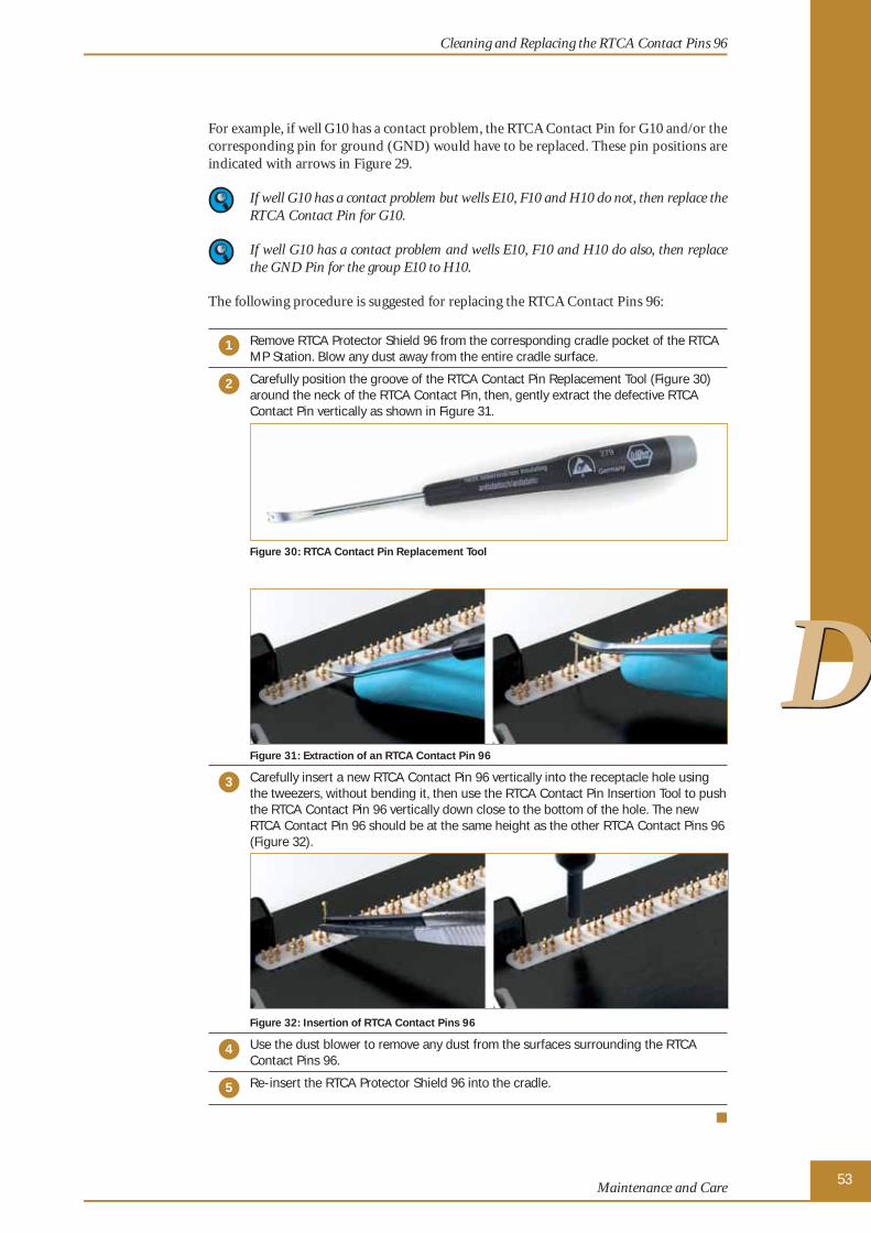
53Maintenance and Care
DD
For example, if well G10 has a contact problem, the RTCA Contact Pin for G10 and/or the corresponding pin for ground (GND) would have to be replaced. These pin positions are indicated with arrows in Figure 29.
If well G10 has a contact problem but wells E10, F10 and H10 do not, then replace the RTCA Contact Pin for G10.
If well G10 has a contact problem and wells E10, F10 and H10 do also, then replace the GND Pin for the group E10 to H10.
The following procedure is suggested for replacing the RTCA Contact Pins 96:
1 Remove RTCA Protector Shield 96 from the corresponding cradle pocket of the RTCA MP Station. Blow any dust away from the entire cradle surface.
2 Carefully position the groove of the RTCA Contact Pin Replacement Tool (Figure 30) around the neck of the RTCA Contact Pin, then, gently extract the defective RTCA Contact Pin vertically as shown in Figure 31.
Figure 30: RTCA Contact Pin Replacement Tool
Figure 31: Extraction of an RTCA Contact Pin 96
3 Carefully insert a new RTCA Contact Pin 96 vertically into the receptacle hole using the tweezers, without bending it, then use the RTCA Contact Pin Insertion Tool to push the RTCA Contact Pin 96 vertically down close to the bottom of the hole. The new RTCA Contact Pin 96 should be at the same height as the other RTCA Contact Pins 96 (Figure 32).
Figure 32: Insertion of RTCA Contact Pins 96
4 Use the dust blower to remove any dust from the surfaces surrounding the RTCA Contact Pins 96.
5 Re-insert the RTCA Protector Shield 96 into the cradle.
■
Cleaning and Replacing the RTCA Contact Pins 96
24050709 MP Instrument Operator's Manual.indb 5324050709 MP Instrument Operator's Manual.indb 53 29.09.2009 14:08:5729.09.2009 14:08:57

54RTCA MP Instrument Operator’s Manual
DD
4. Exchanging FusesIf a fuse need to be replaced, such as after a power surge, follow the procedure below to replace the fuse. If the new fuse burns out again, unplug the RTCA Analyzer power and contact your local Roche representative.
The RTCA Analyzer is equipped with 2-pole fusing. Prior to servicing fuses, ensure that the power switch is in the off “O” position and disconnect the incoming AC power cord. Replace fuses only with the type and rating shown on the Power/Fuse label on the rear panel of the RTCA Analyzer.
Take care to use only Type FSF 5 × 20 fast acting fuses with a 250V, 2A rating. Failure to do so may potentially lead to a fi re and/or personal injury.
1 Using a small, fl at screwdriver, depress the clamps on both sides of the fuse drawer.
Figure 33: Unlocking the fuse drawer.
2 Pull the fuse drawer out of the AC Receptacle. The fuses should remain connected to the drawer.
Figure 34: Pulling out the fuse drawer.
3 Remove the old fuses from the drawer.
���
Exchanging Fuses
24050709 MP Instrument Operator's Manual.indb 5424050709 MP Instrument Operator's Manual.indb 54 29.09.2009 14:09:0029.09.2009 14:09:00

55Maintenance and Care
DD
4 Insert new fuses as shown.
Figure 35: Inserting new fuses in the drawer.
5 Press the fuse drawer, along with the fuses, into the AC Receptacle. Ensure that both ends of the drawer snap completely into place.
Figure 36: Inserting the fuse drawer.
■
Exchanging Fuses
24050709 MP Instrument Operator's Manual.indb 5524050709 MP Instrument Operator's Manual.indb 55 29.09.2009 14:09:0429.09.2009 14:09:04

56RTCA MP Instrument Operator’s Manual
EE
E Appendix
1. Troubleshooting
1.1 I started an experiment and there was an error message, “Cannot fi nd instrument!” What happened?
Figure 37: “Cannot fi nd instrument” error message.
The RTCA Control Unit failed to communicate with the RTCA Analyzer. This message occurs right after one clicks the RTCA Software icon .
Make sure RTCA Analyzer power is on. Check that the RS232 serial cable, linking RTCA Control Unit to RTCA Analyzer (COM port), and the cable connection between RTCA Analyzer and RTCA MP Station, are securely connected. Try the following steps:
1 Turn off the RTCA Analyzer.
2 Disconnect the serial cable from the RTCA Analyzer and from the RTCA Control Unit.
3 Reconnect the cable.
4 Disconnect the fl at cable from the RTCA Analyzer and from the RTCA MP Station.
5 Reconnect the fl at cable.
6 Turn on the RTCA Analyzer.
7 Click Retry.
■
Troubleshooting
I started an experiment and there was an error message, “Cannot fi nd instrument!” What happened?
24050709 MP Instrument Operator's Manual.indb 5624050709 MP Instrument Operator's Manual.indb 56 29.09.2009 14:09:0929.09.2009 14:09:09
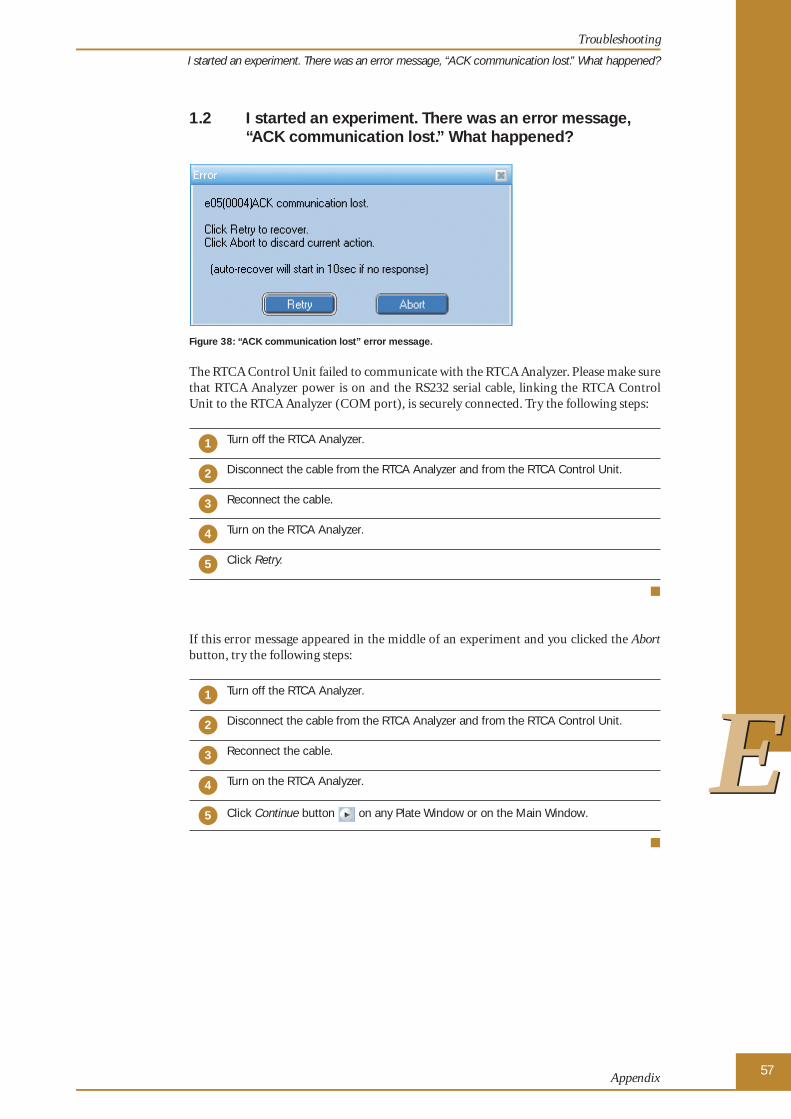
57Appendix
EE
1.2 I started an experiment. There was an error message, “ACK communication lost.” What happened?
Figure 38: “ACK communication lost” error message.
The RTCA Control Unit failed to communicate with the RTCA Analyzer. Please make sure that RTCA Analyzer power is on and the RS232 serial cable, linking the RTCA Control Unit to the RTCA Analyzer (COM port), is securely connected. Try the following steps:
1 Turn off the RTCA Analyzer.
2 Disconnect the cable from the RTCA Analyzer and from the RTCA Control Unit.
3 Reconnect the cable.
4 Turn on the RTCA Analyzer.
5 Click Retry.
■
If this error message appeared in the middle of an experiment and you clicked the Abort button, try the following steps:
1 Turn off the RTCA Analyzer.
2 Disconnect the cable from the RTCA Analyzer and from the RTCA Control Unit.
3 Reconnect the cable.
4 Turn on the RTCA Analyzer.
5 Click Continue button on any Plate Window or on the Main Window.
■
Troubleshooting
I started an experiment. There was an error message, “ACK communication lost.” What happened?
24050709 MP Instrument Operator's Manual.indb 5724050709 MP Instrument Operator's Manual.indb 57 29.09.2009 14:09:0929.09.2009 14:09:09

58RTCA MP Instrument Operator’s Manual
EE
Troubleshooting
I started an experiment and there was a sound and the error message, “No Station.” What happened?
1.3 I started an experiment and there was a sound and the error message, “No Station.” What happened?
Figure 39: “No station” error message.
The RTCA Analyzer failed to communicate with the RTCA MP Station. Please make sure the RTCA Analyzer EPS cable, linking the RTCA Analyzer to the RTCA MP Station, is securely connected. Try the following steps:
1 Turn off the RTCA Analyzer.
2 Disconnect the EPS cable from the RTCA Analyzer and reconnect the cable.
3 Disconnect the EPS cable from the RTCA MP Station and reconnect the cable.
4 Turn on the RTCA Analyzer.
5 Click Retry.
■
1.4 How do I reinitialize the RTCA MP Instrument after a power failure?
1 When the power is restored, restart the RTCA Control Unit. Do not launch the RTCA Software at this time.
2 Turn off the RTCA Analyzer. Wait for 2-3 seconds, and then turn it back on.
3 Launch the RTCA Software and locate the data fi le that was generated before and during the power failure. Open the fi les.
4 Click the Continue button on any Plate Window or on the Main Window. The experiment starts where it left off when power was interrupted.
■
24050709 MP Instrument Operator's Manual.indb 5824050709 MP Instrument Operator's Manual.indb 58 29.09.2009 14:09:0929.09.2009 14:09:09

59Appendix
EE
1.5 The Cell Index signal is signifi cantly lower than usual. Why?
You should take the E-Plate 96 out of the incubator and check the cell status (cell number, cell distribution and morphology) under a microscope. The following are possible reasons:
� Maybe the initial number of cells seeded was not correct.
� Maybe you forgot the step, “leave the E-Plate 96 at room temperature for about 30 minutes” after the cells were seeded. If that step was not done, then cell distribution might not be uniform over the well surface. The cell index signals would be low, espe-cially for the corner wells.
� Maybe there is some type of contamination and cells are dying.
� Maybe the cells were harvested from an over-confl uent fl ask. Our experience is that if the cells in the fl ask were over 80% confl uent, then the cells may not be in the Log phase and the cell status may not be ideal. Such cells may give a low cell index signal when seeded into an E-Plate 96.
� Maybe there is something wrong with the incubator. One likely symptom of incubator problems is that the cell index is lower on edge wells than on the center wells, or the cell index drops to nearly zero faster on the edges than the center wells. Potential problems with incubators may include CO2 level, temperature control, humidity control and certain chemicals released from the incubator. We have encountered several instances where the incubator itself was “toxic” or affecting cell growth. Sometimes a simple but thorough cleaning of the incubator interior may be suffi cient to solve the prob-lems. Alternatively, simply running the experiment in another incubator may solve the problems.
Please make sure, when removing the E-Plate 96 from the incubator, that the instrument is not performing a measurement. If the instrument is waiting for next sweep, make sure that you have enough time to check the cells under a microscope. If you do not have time, you may have to stop the current step and then take the device out of the incubator for assessment. Then Resume the experiment after putting the E-Plate 96 back in.
Troubleshooting
The Cell Index signal is signifi cantly lower than usual. Why?
24050709 MP Instrument Operator's Manual.indb 5924050709 MP Instrument Operator's Manual.indb 59 29.09.2009 14:09:1129.09.2009 14:09:11

60RTCA MP Instrument Operator’s Manual
EE
1.6 The Cell Index signal decreases with time, but there was no compound added. Why?
Remove the E-Plate 96 from the incubator and check the cell status (cell number, cell distribution and morphology) under a microscope. Check for the following:
� Contamination resulting in cells dying.
� Culture media that is too old to support the cell growth, because the experiment took too long.
� Culture media quantity is insuffi cient to support cell growth, due to too much evapo-ration.
� Maybe there is something wrong with the incubator. One likely symptom of incubator problems is that the cell index is lower on edge wells than on the center wells, or the cell index drops to nearly zero faster on the edges than the center wells. Potential problems with incubators may include CO2 level, temperature control, humidity control and certain chemicals released from the incubator. We have encountered several instances where the incubator itself was “toxic” or affecting cell growth. Sometimes a simple but thorough cleaning of the incubator interior may be suffi cient to solve the prob-lems. Alternatively, simply running the experiment in another incubator may solve the problems.
Please make sure, when removing the E-Plate 96 from the incubator, that the instrument is not performing a measurement. If the instrument is waiting for next sweep, make sure that you have enough time to check the cells under a microscope. If you do not have time, you may have to stop the current step and then take the device out of the incubator for assessment. Then Resume the experiment after putting the E-Plate 96 back in.
1.7 The Cell Index signal is signifi cantly higher than usual. Why?
Remove the E-Plate 96 from the incubator and check the cell status (cell number, cell distribution and morphology) under a microscope. It is possible that the initial seeding number was high.
Please make sure, when removing the E-Plate 96 from the incubator, that the instrument is not performing a measurement. If the instrument is waiting for next sweep, make sure that you have enough time to check the cells under a microscope. If you do not have time, you may have to stop the current step and then take the device out of the incubator for assessment. Then Resume the experiment after putting the E-Plate 96 back in.
Troubleshooting
The Cell Index signal decreases with time, but there was no compound added. Why?
24050709 MP Instrument Operator's Manual.indb 6024050709 MP Instrument Operator's Manual.indb 60 29.09.2009 14:09:1129.09.2009 14:09:11

61Appendix
EE
1.8 I did a background measurement. The RTCA Software indicated that many wells may have background problems. What should I do?
Please unlock the cradle, remove the E-Plate 96 from the cradle, ensure that the contact pads on the E-Plate 96 are clean and re-insert the E-Plate 96. Then perform Scan Plate. Check the Message page for results to see whether you have many wells showing connection problems. You can also check the plate scanning data shown on the Cell Index Page of the corresponding Plate Window. You can check whether any measured well values show an open circuit (i.e., the resistance values are abnormally high, for example, more than 500 ohm) or are negative. If the scan-plate Message page shows Plate Scanned. Connections ok, then you should be able to re-start the experiment. Note that the RTCA Software may still indicate that a few wells may have background problems since the software has strict criteria for determining whether a well has a good background. A well that is indicated as “may have background problems” does not always cause an experimental problem.
If the message indicates connection problems with many wells or if the plate-scanning data fi le shows many wells having open circuits, there may be problems with the E-Plate 96 or RTCA MP Station or both. Please perform an additional Scan Plate after removing the problem E-Plate 96 from RTCA MP Station and then re-inserting/repositioning it in the Station. Check the Scan Plate results again, as described above, to see whether the results for the wells concerned are similar to previous results. If problems do not occur in the 2nd Scan Plate, experiments can be continued. The initial issue may be related to the insertion or positioning of the E-Plate 96 into the RTCA MP Station.
If the results for wells with connection problems or open-circuit wells are similar to previous results, the E-Plate 96, the RTCA MP Station or both have problems.
First, please check to see whether the E-Plate 96 or RTCA MP Station is damaged. If so, contact your local Roche representative.
Second, if there is no visible damage, see whether all connector pads on the E-Plate 96 are clean and free of dust/dirt particles. If not, clean the connector pads on the E-Plate 96 with a tissue wetted with 80% alcohol. After this cleaning, re-insert and reposition the E-Plate 96 for another Scan Plate test. If the number of open-circuit wells is the same as before, then please report the problems to your local Roche representative.
Troubleshooting
I did a background measurement. The RTCA Software indicated that many wells may have background problems. What should I do?
24050709 MP Instrument Operator's Manual.indb 6124050709 MP Instrument Operator's Manual.indb 61 29.09.2009 14:09:1129.09.2009 14:09:11

62RTCA MP Instrument Operator’s Manual
EE
1.9 I placed an E-Plate 96 into a cradle of the RTCA MP Station. The Device Indicating LED did not turn orange. What should I do?
First, check whether a RTCA Protector Shield 96 is placed properly inside the cradle pocket.
Second, check whether the E-Plate 96 has a 96x lid covering the E-Plate 96.
Third, after checking the above two items, remove the E-Plate from the RTCA MP Station. Then turn off the RTCA Analyzer. After 5 seconds, turn on the RTCA Analyzer. Then re-insert the E-Plate 96 into the cradle of the RTCA MP Station and close the clamp plate with the handle in front of the cradle. Check whether the Device Indicating LED turns orange. If the LED did not turn orange (no light), then please contact your local Roche representative.
1.10 I am contacting the local Roche representative or Roche Technical Support. What data fi les should be sent?
In case of inquiries or complaints, ALWAYS SEND the database fi le (*.plt), including the experiment data and information. Alternatively, please use the Problem Report function, which is available under the File pull-down menu on each Plate Window, to create an Problem Report. The RTCA Software will provide an option that allows you to remove any confi dential information from your experiment. Do not include any confi dential information in the fi les that are sent. Please remove any information that is confi dential. After the Problem Report is created, please SEND the Problem Report fi le (Err_YYMMDD****.zip).
Troubleshooting
I placed an E-Plate 96 into a cradle of the RTCA MP Station. The Device Indicating LED did not turn orange. What should I do?
24050709 MP Instrument Operator's Manual.indb 6224050709 MP Instrument Operator's Manual.indb 62 29.09.2009 14:09:1129.09.2009 14:09:11

63Appendix
EE
2. Ordering InformationRoche Applied Science offers a large selection of reagents and systems for life science research. For a complete overview of related products and information, please visit and bookmark our home page, www.roche-applied-science.com, and visit our special interest sites for
� The xCELLigence System:www.roche-applied-science.com/sis/xcelligence
� Apoptosis and Cell Proliferation:www.roche-applied-science.com/sis/apoptosis
� Cutting-Edge Transfection Reagents:www.roche-applied-science.com/sis/transfection
Roche Applied Science Service and Support
At Roche Applied Science we are committed to providing innovative, high-quality instru-ments and reagents combined with excellent customer service – offering powerful tools to address the evolving needs of life science researchers worldwide.
Whether you need expert technical support, online access to comprehensive product in-formation, convenient on-site product supply service and online ordering, or outstanding customer service to ensure accurate and timely product delivery, we provide a wealth of resources to help you achieve your research goals.
For more information, visit www.roche-applied-science.com to explore our products and services or to fi nd a local representative.
RTCA Analyzer Cat. No. 05 228 972 001
RTCA MP Station Cat. No. 05 331 625 001
RTCA Control Unit 1.1 Cat. No. 05 454 417 001
RTCA Protector Shield 96 Cat. No. 05 288 967 001
RTCA Resistor Plate 96 Cat. No. 05 232 350 001
RTCA Frame 96 Cat. No. 05 232 392 001
E-Plate 966 Units Cat. No. 05 232 368 001
6 × 6 Units Cat. No. 05 232 376 001
RTCA Contact Pins 96 (20 units) Cat. No. 05 232 384 001
RTCA Software Package 1.2 Cat. No. 05 454 433 001
Ordering Information
24050709 MP Instrument Operator's Manual.indb 6324050709 MP Instrument Operator's Manual.indb 63 29.09.2009 14:09:1129.09.2009 14:09:11

Published by
Roche Diagnostics GmbHRoche Applied Science68298 MannheimGermany
© 2009 Roche Diagnostics All rights reserved.
05358051001�1109
24050709 MP Instrument Operator's Manual.indb 6424050709 MP Instrument Operator's Manual.indb 64 29.09.2009 14:09:1129.09.2009 14:09:11