Embed Size (px)
Citation preview

Te
st &
Mea
sure
men
t
Data
She
et |
09.0
0
R&S®SMB100ARF and Microwave Signal GeneratorSpecifications
year
SMB100A_dat-sw_en_5213-8396-22_v0900_cover.indd 1 14.07.2016 19:10:02
Version 09.00, July 2016
2 Rohde & Schwarz R&S®SMB100A RF and Microwave Signal Generator
CONTENTS Definitions ....................................................................................................................................................................... 3
Specifications .................................................................................................................................................................. 4
Hardware and software option concept .............................................................................................................................................. 4
RF performance................................................................................................................................................................................. 4
Frequency ...................................................................................................................................................................................... 4
Frequency sweep ........................................................................................................................................................................... 5
Reference frequency ...................................................................................................................................................................... 5
Level.................................................................................................................................................................................................. 6
Level settings ................................................................................................................................................................................. 6
Level performance ......................................................................................................................................................................... 7
Level setting times ......................................................................................................................................................................... 8
Reverse power ............................................................................................................................................................................... 8
VSWR ............................................................................................................................................................................................ 8
Level sweep ................................................................................................................................................................................. 12
Spectral purity ................................................................................................................................................................................. 13
List mode settings ............................................................................................................................................................................ 18
Analog modulation ........................................................................................................................................................................... 19
Simultaneous modulation ............................................................................................................................................................. 19
Amplitude modulation ................................................................................................................................................................... 19
Frequency bands for frequency and phase modulation ................................................................................................................ 19
Frequency modulation .................................................................................................................................................................. 20
Phase modulation ........................................................................................................................................................................ 21
Pulse modulation (R&S®SMB-K21 or R&S®SMB-K22 option) ....................................................................................................... 22
Input for external modulation signals ............................................................................................................................................ 23
Modulation sources ......................................................................................................................................................................... 24
Internal modulation generator (LF) ............................................................................................................................................... 24
LF frequency sweep ..................................................................................................................................................................... 24
Pulse generator (R&S®SMB-K23 option) ...................................................................................................................................... 25
Pulse train (R&S®SMB-K27 option) .............................................................................................................................................. 25
Stereo/RDS coder (R&S®SMB-B5 option) .................................................................................................................................... 26
Remote control ................................................................................................................................................................................ 27
Connectors ...................................................................................................................................................................................... 28
Front panel connectors................................................................................................................................................................. 28
Rear panel connectors ................................................................................................................................................................. 28
General data .................................................................................................................................................................................... 29
Ordering information .................................................................................................................................................... 30

Version 09.00, July 2016
Rohde & Schwarz R&S®SMB100A RF and Microwave Signal Generator 3
Definitions General
Product data applies under the following conditions:
Three hours storage at ambient temperature followed by 30 minutes warm-up operation
Specified environmental conditions met
Recommended calibration interval adhered to
All internal automatic adjustments performed, if applicable
Specifications with limits
Represent warranted product performance by means of a range of values for the specified parameter. These specifications are
marked with limiting symbols such as <, ≤, >, ≥, ±, or descriptions such as maximum, limit of, minimum. Compliance is ensured by
testing or is derived from the design. Test limits are narrowed by guard bands to take into account measurement uncertainties, drift
and aging, if applicable.
Specifications without limits
Represent warranted product performance for the specified parameter. These specifications are not specially marked and represent
values with no or negligible deviations from the given value (e.g. dimensions or resolution of a setting parameter). Compliance is
ensured by design.
Typical data (typ.)
Characterizes product performance by means of representative information for the given parameter. When marked with <, > or as a
range, it represents the performance met by approximately 80 % of the instruments at production time. Otherwise, it represents the
mean value.
Nominal values (nom.)
Characterize product performance by means of a representative value for the given parameter (e.g. nominal impedance). In contrast to
typical data, a statistical evaluation does not take place and the parameter is not tested during production.
Measured values (meas.)
Characterize expected product performance by means of measurement results gained from individual samples.
Uncertainties
Represent limits of measurement uncertainty for a given measurand. Uncertainty is defined with a coverage factor of 2 and has been
calculated in line with the rules of the Guide to the Expression of Uncertainty in Measurement (GUM), taking into account
environmental conditions, aging, wear and tear.
Device settings and GUI parameters are designated with the format “parameter: value”.
Typical data as well as nominal and measured values are not warranted by Rohde & Schwarz.

Version 09.00, July 2016
4 Rohde & Schwarz R&S®SMB100A RF and Microwave Signal Generator
Specifications
Hardware and software option concept The available frequency ranges and the corresponding hardware and software options are shown in the tables.
9 kHz to 1.1 GHz 9 kHz to 2.2 GHz 9 kHz to 3.2 GHz 9 kHz to 6 GHz
With electronic step attenuator R&S®SMB-B101 R&S®SMB-B102 R&S®SMB-B103 R&S®SMB-B106
With mechanical step attenuator – – – –
Without step attenuator – – – –
High power standard
OCXO reference oscillator 1 R&S®SMB-B1
OCXO reference oscillator, high
performance 1
R&S®SMB-B1H
Reverse power protection standard
Stereo/RDS coder R&S®SMB-B5
Pulse modulator R&S®SMB-K22
Pulse generator R&S®SMB-K23
Pulse train 2 R&S®SMB-K27
100 kHz to 12.75 GHz 100 kHz to 20 GHz 100 kHz to 31.8 GHz 100 kHz to 40 GHz
With electronic step attenuator R&S®SMB-B112 – – –
With mechanical step attenuator – R&S®SMB-B120 R&S®SMB-B131 R&S®SMB-B140,
R&S®SMB-B140N
Without step attenuator R&S®SMB-B112L R&S®SMB-B120L – R&S®SMB-B140L
High power standard R&S®SMB-B31 R&S®SMB-B32 R&S®SMB-B32
Low harmonic filter – R&S®SMB-B25 R&S®SMB-B26 R&S®SMB-B26
OCXO reference oscillator 1 R&S®SMB-B1
OCXO reference oscillator,
high performance 1
R&S®SMB-B1H
Reverse power protection R&S®SMB-B30 –
Stereo/RDS coder – –
Pulse modulator R&S®SMB-K21
Pulse generator R&S®SMB-K23
Pulse train 2 R&S®SMB-K27
RF performance
Frequency
Range R&S®SMB-B101 9 kHz to 1.1 GHz
R&S®SMB-B102 9 kHz to 2.2 GHz
R&S®SMB-B103 9 kHz to 3.2 GHz
R&S®SMB-B106 9 kHz to 6 GHz
R&S®SMB-B112, R&S®SMB-B112L 100 kHz to 12.75 GHz
R&S®SMB-B120, R&S®SMB-B120L 100 kHz to 20 GHz
R&S®SMB-B131 100 kHz to 31.8 GHz
R&S®SMB-B140, R&S®SMB-B140L,
R&S®SMB-B140N
100 kHz to 40 GHz
Resolution of setting 0.001 Hz
Resolution of synthesis f = 1 GHz 0.44 μHz (nom.)
Setting time to within < 1 × 10⁻⁷ for f > 200 MHz or < 20 Hz for f ≤ 200 MHz
Specification does not apply when frequency crosses 20 GHz.
Specification does not apply to instruments equipped with R&S®SMB-B120/-B131/-B140 when
frequency crosses 200 kHz.
after IEC/IEEE bus delimiter
ALC state on < 3 ms
ALC state sample&hold, f ≤ 20 GHz < 7 ms
ALC state sample&hold, f > 20 GHz < 10 ms
after trigger pulse in list mode < 1 ms
Resolution of phase offset setting 0.1°
1 Only one of the R&S®SMB-B1 or R&S®SMB-B1H option can be installed. 2 Requires the R&S®SMB-K23 option; only available for instruments with serial number > 102400.

Version 09.00, July 2016
Rohde & Schwarz R&S®SMB100A RF and Microwave Signal Generator 5
Frequency sweep
Operating mode digital sweep in discrete steps
Trigger mode free run automatic
full sweep single
execute one step step
external trigger only start/stop
Trigger source keyboard, external trigger, remote control
Trigger slope positive, negative
Sweep range full frequency range
Sweep shape triangle, sawtooth
Step spacing linear, logarithmic
Step size linear full frequency range, min. 0.001 Hz
logarithmic 0.01 % to 100 %
Dwell time range 10 ms to 10 s
Dwell time resolution 0.1 ms
Reference frequency
Frequency error at time of calibration in production < 1 × 10⁻⁷
with R&S®SMB-B1/R&S®SMB-B1H option < 1 × 10⁻⁸
Aging
(after 10 days of uninterrupted operation)
standard < 1 × 10⁻⁶/year
with R&S®SMB-B1 option < 1 × 10⁻⁹/day, < 1 × 10⁻⁷/year
with R&S®SMB-B1H option < 5 × 10⁻¹⁰/day, < 3 × 10⁻⁸/year
Temperature effect (0 °C to +50 °C) standard < 2 × 10⁻⁶
with R&S®SMB-B1 option < 1 × 10⁻⁷
with R&S®SMB-B1H option < 1 × 10⁻⁸
Warm-up time to nominal thermostat temperature with
R&S®SMB-B1/R&S®SMB-B1H option
≤ 10 min
Reference frequency output
Connector type REF OUT on rear panel BNC female
Output frequency sine wave
instrument set to internal reference 10 MHz
instrument set to external reference applied external reference frequency
Output level +7 dBm to +13 dBm, +10 dBm (typ.)
Source impedance 50 Ω (nom.)
Reference frequency input
Connector type REF IN on rear panel BNC female
Input frequency 5 MHz, 10 MHz
Frequency locking range ± 3 × 10⁻⁶
Input level range 0 dBm to +16 dBm
Input impedance 50 Ω (nom.)
Version 09.00, July 2016
6 Rohde & Schwarz R&S®SMB100A RF and Microwave Signal Generator
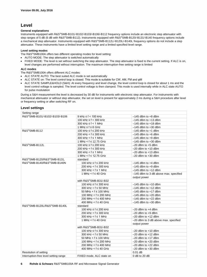
Level General explanations
Instruments equipped with R&S®SMB-B101/-B102/-B103/-B106/-B112 frequency options include an electronic step attenuator with
step ranges of 5 dB (6 dB with R&S®SMB-B112). Instruments equipped with R&S®SMB-B120/-B131/-B140 frequency options include
a mechanical step attenuator. Instruments equipped with R&S®SMB-B112L/-B120L/-B140L frequency options do not include a step
attenuator. These instruments have a limited level setting range and a limited specified level range.
Level setting modes
The R&S®SMB100A offers two different operating modes for level setting:
AUTO MODE: The step attenuator is switched automatically
FIXED MODE: The level is set without switching the step attenuator. The step attenuator is fixed to the current setting. If ALC is on,
level changes are performed without interruption. The maximum interruption-free setting range is limited
ALC modes
The R&S®SMB100A offers different ALC modes:
ALC STATE AUTO: The best suited ALC mode is set automatically
ALC STATE on: The level control loop is closed. This mode is suitable for CW, AM, FM and φM
ALC STATE SAMPLE&HOLD (S&H): At every frequency and level change, the level control loop is closed for about 1 ms and the
level control voltage is sampled. The level control voltage is then clamped. This mode is used internally while in ALC state AUTO
for pulse modulation
During a S&H measurement the level is decreased by 30 dB for instruments with electronic step attenuator. For instruments with
mechanical attenuator or without step attenuator, the set on level is present for approximately 2 ms during a S&H procedure after level
or frequency setting or after switching RF on.
Level settings
Setting range
R&S®SMB-B101/-B102/-B103/-B106 9 kHz ≤ f < 100 kHz –145 dBm to +8 dBm
100 kHz ≤ f < 300 kHz –145 dBm to +13 dBm
300 kHz ≤ f < 1 MHz –145 dBm to +18 dBm
1 MHz ≤ f ≤ 6 GHz –145 dBm to +30 dBm
R&S®SMB-B112 100 kHz ≤ f ≤ 200 kHz –145 dBm to +1 dBm
200 kHz < f ≤ 300 kHz –145 dBm to +6 dBm
300 kHz < f ≤ 1 MHz –145 dBm to +9 dBm
1 MHz < f ≤ 12.75 GHz –145 dBm to +30 dBm
R&S®SMB-B112L 100 kHz ≤ f ≤ 200 kHz –20 dBm to +5 dBm
200 kHz < f ≤ 300 kHz –20 dBm to +10 dBm
300 kHz < f ≤ 1 MHz –20 dBm to +13 dBm
1 MHz < f ≤ 12.75 GHz –20 dBm to +30 dBm
R&S®SMB-B120/R&S®SMB-B131,
R&S®SMB-B140/R&S®SMB-B140N
standard
100 kHz ≤ f ≤ 200 kHz –145 dBm to +4 dBm
200 kHz < f ≤ 300 kHz –145 dBm to +9 dBm
300 kHz < f ≤ 1 MHz –145 dBm to +12 dBm
1 MHz < f ≤ 40 GHz –145 dBm to 3 dB above max. specified
output power
with R&S®SMB-B31/-B32
100 kHz ≤ f ≤ 300 kHz –145 dBm to +10 dBm
300 kHz < f ≤ 50 MHz –145 dBm to +12 dBm
50 MHz < f ≤ 100 MHz –145 dBm to +17 dBm
100 MHz < f ≤ 200 MHz –145 dBm to +20 dBm
200 MHz < f ≤ 400 MHz –145 dBm to +22 dBm
400 MHz < f ≤ 40 GHz –145 dBm to +30 dBm
R&S®SMB-B120L/R&S®SMB-B140L standard
100 kHz ≤ f ≤ 200 kHz –20 dBm to +4 dBm
200 kHz < f ≤ 300 kHz –20 dBm to +9 dBm
300 kHz < f ≤ 1 MHz –20 dBm to +12 dBm
1 MHz < f ≤ 40 GHz –20 dBm to 3 dB above max. specified
output power
with R&S®SMB-B31/-B32
100 kHz ≤ f ≤ 300 kHz –20 dBm to +10 dBm
300 kHz < f ≤ 50 MHz –20 dBm to +12 dBm
50 MHz < f ≤ 100 MHz –20 dBm to +17 dBm
100 MHz < f ≤ 200 MHz –20 dBm to +20 dBm
200 MHz < f ≤ 400 MHz –20 dBm to +22 dBm
400 MHz < f ≤ 40 GHz –20 dBm to +30 dBm
Resolution of setting 0.01 dB
Interruption-free level setting range FIXED mode, ALC state on 0 dB to 20 dB

Version 09.00, July 2016
Rohde & Schwarz R&S®SMB100A RF and Microwave Signal Generator 7
Level performance
Specified level range, peak envelope power (PEP)
R&S®SMB-B101/-B102/-B103/-B106 9 kHz ≤ f ≤ 200 kHz –120 dBm to +5 dBm
200 kHz < f ≤ 1 MHz –120 dBm to +13 dBm
1 MHz < f ≤ 6 GHz –120 dBm to +18 dBm
R&S®SMB-B112 standard
200 kHz < f ≤ 1 MHz –120 dBm to +6 dBm
1 MHz < f ≤ 12.75 GHz –120 dBm to +18 dBm
with R&S®SMB-B30 option
200 kHz < f ≤ 1 MHz –120 dBm to +5 dBm
1 MHz < f ≤ 12.75 GHz –120 dBm to +15 dBm
R&S®SMB-B112L standard
200 kHz < f ≤ 1 MHz –5 dBm to +10 dBm
1 MHz < f ≤ 12.75 GHz –5 dBm to +18 dBm
with R&S®SMB-B30 option
200 kHz < f ≤ 1 MHz –5 dBm to +9 dBm
1 MHz < f ≤ 12.75 GHz –5 dBm to +15 dBm
R&S®SMB-B120 standard
200 kHz < f ≤ 10 MHz –120 dBm to +5 dBm
10 MHz < f ≤ 50 MHz –120 dBm to +10 dBm
50 MHz < f ≤ 20 GHz –120 dBm to +11 dBm
with R&S®SMB-B31 option 3
200 kHz < f ≤ 10 MHz –120 dBm to +5 dBm
10 MHz < f ≤ 50 MHz –120 dBm to +10 dBm
50 MHz < f ≤ 20 GHz –120 dBm to +16 dBm
R&S®SMB-B120L standard
200 kHz < f ≤ 10 MHz 0 dBm to +5 dBm
10 MHz < f ≤ 50 MHz 0 dBm to +10 dBm
50 MHz < f ≤ 20 GHz 0 dBm to +14 dBm
with R&S®SMB-B31 option 3
200 kHz < f ≤ 10 MHz 0 dBm to +5 dBm
10 MHz < f ≤ 50 MHz 0 dBm to +10 dBm
50 MHz < f ≤ 100 MHz 0 dBm to +16 dBm
100 MHz < f ≤ 20 GHz 0 dBm to +19 dBm
R&S®SMB-B131 standard
200 kHz < f ≤ 10 MHz –120 dBm to +5 dBm
10 MHz < f ≤ 31.8 GHz –120 dBm to +8 dBm
with R&S®SMB-B32 option 3
200 kHz < f ≤ 10 MHz –120 dBm to +5 dBm
10 MHz < f ≤ 50 MHz –120 dBm to +9 dBm
50 MHz < f ≤ 31.8 GHz –120 dBm to +13 dBm
R&S®SMB-B140,
R&S®SMB-B140N
standard
200 kHz < f ≤ 10 MHz –120 dBm to +5 dBm
10 MHz < f ≤ 40 GHz –120 dBm to +8 dBm
with R&S®SMB-B32 option 3
200 kHz < f ≤ 10 MHz –120 dBm to +5 dBm
10 MHz < f ≤ 50 MHz –120 dBm to +9 dBm
50 MHz < f ≤ 40 GHz –120 dBm to +13 dBm
R&S®SMB-B140L standard
200 kHz < f ≤ 10 MHz 0 dBm to +5 dBm
10 MHz < f ≤ 50 MHz 0 dBm to +9 dBm
50 MHz < f ≤ 40 GHz 0 dBm to +11 dBm
with R&S®SMB-B32 option 3
200 kHz < f ≤ 10 MHz 0 dBm to +5 dBm
10 MHz < f ≤ 50 MHz 0 dBm to +9 dBm
50 MHz < f ≤ 40 GHz 0 dBm to +16 dBm
3 For instruments equipped with R&S®SMB-B25 or R&S®SMB-B26 option, the specification is valid with low harmonic filter off.
With low harmonic filter on, the standard level range is valid.

Version 09.00, July 2016
8 Rohde & Schwarz R&S®SMB100A RF and Microwave Signal Generator
Level error ALC state on, temperature range +18 °C to +33 °C
R&S®SMB-B101/-B102/-B103/
-B106/-B112
9 kHz ≤ f ≤ 200 kHz 4 < 1.0 dB
200 kHz < f ≤ 3 GHz < 0.5 dB
f > 3 GHz < 0.9 dB
R&S®SMB-B112L 200 kHz < f ≤ 3 GHz < 0.7 dB
f > 3 GHz < 1.1 dB
R&S®SMB-B120L/-B140L 200 kHz < f ≤ 3 GHz < 0.7 dB
3 GHz < f ≤ 20 GHz < 1.1 dB
20 GHz < f ≤ 40 GHz < 1.2 dB
R&S®SMB-B120/-B131,
R&S®SMB-B140/-B140N
level > –90 dBm level ≤ –90 dBm
200 kHz < f ≤ 3 GHz < 0.5 dB < 0.5 dB
3 GHz < f ≤ 20 GHz < 0.9 dB < 1.2 dB
20 GHz < f ≤ 40 GHz < 1.0 dB < 1.5 dB
Additional level error ALC state S&H < 0.25 dB
Level setting times
Setting time level deviation < 0.1 dB 5 from final value, with GUI update stopped, temperature range
+18 °C to +33 °C, without switching of the mechanical step attenuator
after IEC/IEEE bus delimiter
ALC state on < 2.5 ms
ALC state S&H, f ≤ 20 GHz < 7 ms
ALC state S&H, f > 20 GHz < 10 ms
in list mode after trigger pulse < 1 ms
with switching of the mechanical step attenuator
ALC state on < 25 ms
ALC state S&H < 30 ms
Reverse power
The R&S®SMB100A equipped with R&S®SMB-B101/-B102/-B103/-B106 frequency options includes a reverse power protection as
standard. For instruments equipped with the R&S®SMB-B112 or R&S®SMB-B112L frequency option, a reverse power protection
option (R&S®SMB-B30) is available.
Maximum permissible RF power in output frequency range of RF path for f > 1 MHz, from source ≥ 50 Ω
Instruments with reverse power protection
Reverse power 1 MHz < f ≤ 1 GHz 50 W
1 GHz < f ≤ 2 GHz 25 W
2 GHz < f ≤ 12.75 GHz 10 W
Maximum permissible DC voltage 35 V
Instruments without reverse power protection
Reverse power 0.5 W
Maximum permissible DC voltage R&S®SMB-B112/-B112L 35 V
R&S®SMB-B120/-B120L,
R&S®SMB-B131,
R&S®SMB-B140/-B140L/-B140N
0 V
VSWR
Output impedance VSWR in 50 Ω system, ALC state on
R&S®SMB-B101/-B102/-B103/-B106/
-B112
f > 200 kHz < 1.8
R&S®SMB-B112L/-B30 f > 200 kHz < 2.0
R&S®SMB-B120/-B131,
R&S®SMB -B140/-B140N
1 MHz < f ≤ 20 GHz < 1.6 (meas.)
20 GHz < f ≤ 40 GHz < 1.8 (meas.)
4 Only for instruments equipped with an R&S®SMB-B101, R&S®SMB-B102, R&S®SMB-B103 or R&S®SMB-B106 option. 5 Level deviation < 0.25 dB for f ≤ 23.4375 MHz for instruments equipped with an R&S®SMB-B112/-B112L/-B120/-B120L/-B131/-B140/-B140L/-B140N
option

Version 09.00, July 2016
Rohde & Schwarz R&S®SMB100A RF and Microwave Signal Generator 9
Maximum available output level versus frequency (meas.).
Maximum available output level versus frequency (meas.).
Version 09.00, July 2016
10 Rohde & Schwarz R&S®SMB100A RF and Microwave Signal Generator
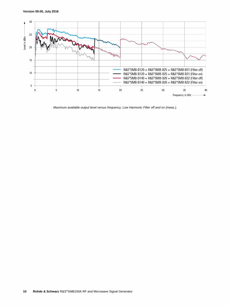
Maximum available output level versus frequency, Low Harmonic Filter off and on (meas.).
Version 09.00, July 2016
Rohde & Schwarz R&S®SMB100A RF and Microwave Signal Generator 11
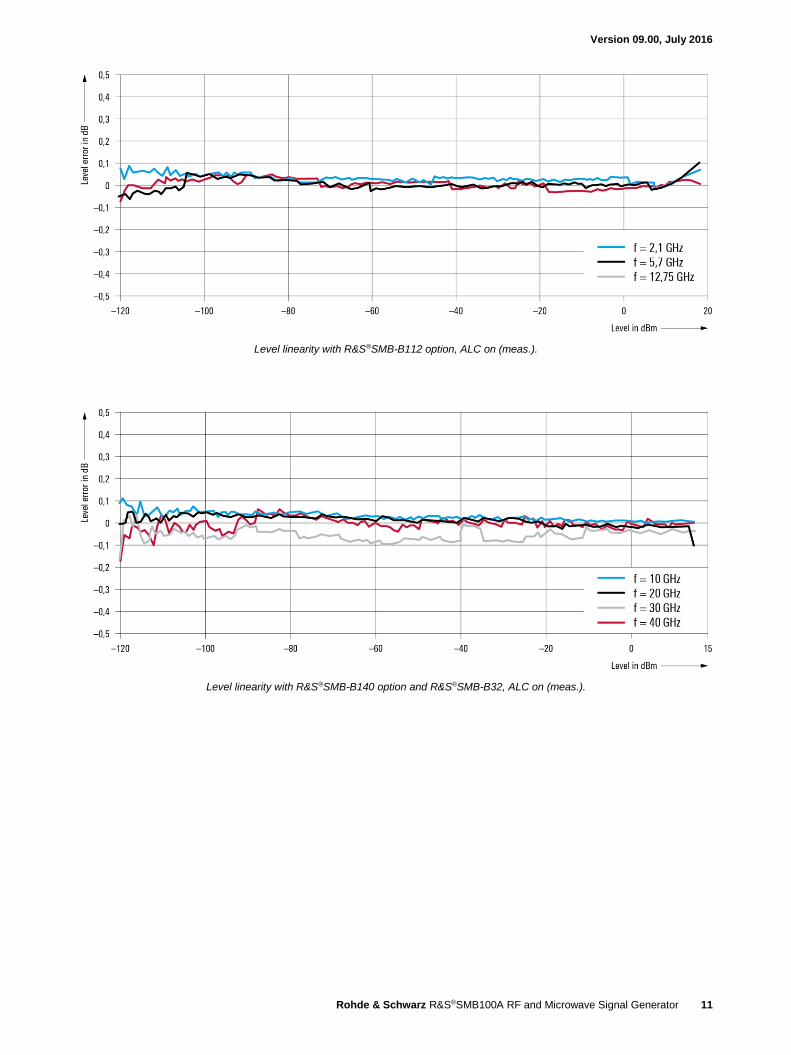
Level linearity with R&S®SMB-B112 option, ALC on (meas.).
Level linearity with R&S®SMB-B140 option and R&S®SMB-B32, ALC on (meas.).

Version 09.00, July 2016
12 Rohde & Schwarz R&S®SMB100A RF and Microwave Signal Generator
Level sweep
Operating mode digital sweep in discrete steps
Trigger mode free run automatic
full sweep single
execute one step step
external trigger only start/stop
Trigger source keyboard, external connector, remote
control
Trigger slope with external trigger positive, negative
Sweep range full specified level range
interruption-free –20 dB to +20 dB
Sweep shape triangle, sawtooth
Step spacing logarithmic
Step size setting resolution 0.01 dB
Dwell time setting range 10 ms to 10 s
Dwell time setting resolution 0.1 ms
Version 09.00, July 2016
Rohde & Schwarz R&S®SMB100A RF and Microwave Signal Generator 13
Spectral purity Harmonics
R&S®SMB-B101/-B102/-B103/-B106/
-B112/-B112L
1 MHz < f ≤ 6 GHz; level ≤ 13 dBm 6
f > 6 GHz; level ≤ 10 dBm 6
< –30 dBc
R&S®SMB-B120/-B120L/-B131,
R&S®SMB-B140/-B140L/-B140N
standard; level ≤ 8 dBm 6
f > 1 MHz < –30 dBc
with R&S®SMB-B25, R&S®SMB-B26 option low harmonic,
low harmonic filter on, level ≤ 10 dBm 6
1 MHz < f ≤ 150 MHz < –30 dBc
150 MHz < f ≤ 3 GHz < –58 dBc
3 GHz < f ≤ 20 GHz < –50 dBc
f > 20 GHz < –60 dBc (meas)
Nonharmonics CW, level > –10 dBm (level > 0 dBm for instruments without step attenuator),
offset > 10 kHz from carrier
f ≤ 23.4375 MHz < –70 dBc
23.4375 MHz < f ≤ 1500 MHz < –70 dBc, < –84 dBc (typ.)
1500 MHz < f ≤ 3 GHz < –64 dBc, < –78 dBc (typ.)
3 GHz < f ≤ 6.375 GHz < –58 dBc, < –72 dBc (typ.)
6.375 GHz < f ≤ 12.75 GHz < –52 dBc, < –66 dBc (typ.)
12.75 GHz < f ≤ 25.5 GHz < –46 dBc, < –60 dBc (typ.)
25.5 GHz < f ≤ 40 GHz < –40 dBc, < –54 dBc (typ.)
Subharmonics level > –10 dBm (level > 0 dBm for instruments without step attenuator)
f < 6.375 GHz none
6.375 GHz < f ≤ 20 GHz < –55 dBc
20 GHz < f ≤ 40 GHz < –50 dBc
Wideband noise level operating mode auto, level > 10 dBm 6, measurement bandwidth 1 Hz, CW
carrier offset 10 MHz
15 MHz < f ≤ 6.375 GHz < –142 dBc
carrier offset 30 MHz
6.375 GHz < f ≤ 12.75 GHz < –138 dBc
12.75 GHz < f ≤ 20 GHz < –135 dBc
20 GHz < f ≤ 40 GHz < –132 dBc
SSB phase noise carrier offset 20 kHz, measurement bandwidth 1 Hz, CW
f = 100 MHz, level = 10 dBm < –141 dBc, –145 dBc (typ.)
f = 1 GHz < –122 dBc, –128 dBc (typ.)
f = 2 GHz < –116 dBc, –122 dBc (typ.)
f = 3 GHz < –112 dBc, –118 dBc (typ.)
f = 4 GHz < –110 dBc, –116 dBc (typ.)
f = 6 GHz < –106 dBc, –112 dBc (typ.)
f = 10 GHz < –102 dBc, –108 dBc (typ.)
f = 20 GHz < –96 dBc, –102 dBc (typ.)
f = 30 GHz < –92 dBc, –98 dBc (typ.)
f = 40 GHz < –90 dBc, –96 dBc (typ.)
RMS jitter f = 1 GHz, BW = 1 Hz to 10 MHz, CW
standard 7.2 ps (meas.), (7.2 mUI)
with R&S®SMB-B1 option 1.3 ps (meas.), (1.3 mUI)
with R&S®SMB-B1H option 105 fs (meas.), (105 µUI)
f = 155 MHz,
bandwidth = 100 Hz to 1.5 MHz, CW
83 fs (meas.), (12.9 µUI)
f = 622 MHz,
bandwidth = 1 kHz to 5 MHz, CW
63 fs (meas.), (39.2 µUI)
f = 2.488 GHz,
bandwidth = 5 kHz to 15 MHz, CW
55 fs (meas.), (137 µUI)
Residual FM RMS value at f = 1 GHz, CW
0.3 kHz to 3 kHz, weighted (ITU-T) < 4 Hz, 0.22 Hz (typ.)
0.03 kHz to 23 kHz < 10 Hz, 1.35 Hz (typ.)
Residual AM RMS value (0.03 kHz to 20 kHz), CW
level = 8 dBm
< 0.02 %
6 Or maximum specified output power, whichever is lower.
Version 09.00, July 2016
14 Rohde & Schwarz R&S®SMB100A RF and Microwave Signal Generator
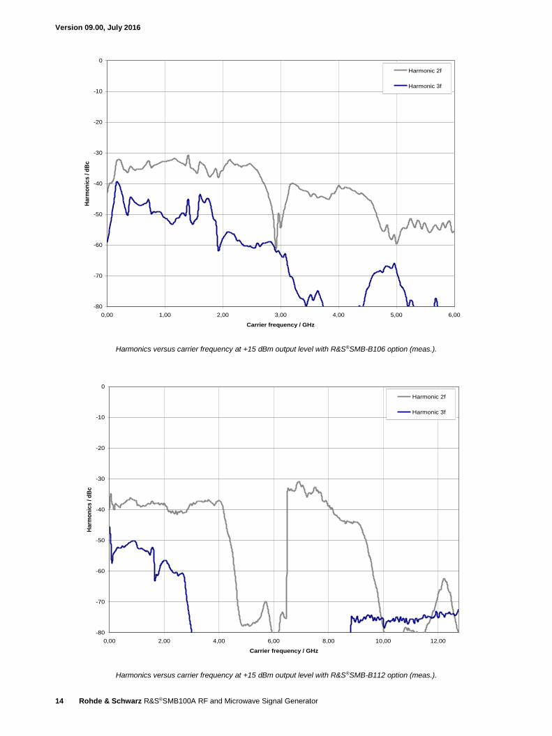
Harmonics versus carrier frequency at +15 dBm output level with R&S®SMB-B106 option (meas.).
Harmonics versus carrier frequency at +15 dBm output level with R&S®SMB-B112 option (meas.).
-80
-70
-60
-50
-40
-30
-20
-10
0
0,00 1,00 2,00 3,00 4,00 5,00 6,00
Carrier frequency / GHz
Harm
on
ics
/ d
Bc
Harmonic 2f
Harmonic 3f
-80
-70
-60
-50
-40
-30
-20
-10
0
0,00 2,00 4,00 6,00 8,00 10,00 12,00
Carrier frequency / GHz
Harm
on
ics
/ d
Bc
Harmonic 2f
Harmonic 3f
Version 09.00, July 2016
Rohde & Schwarz R&S®SMB100A RF and Microwave Signal Generator 15
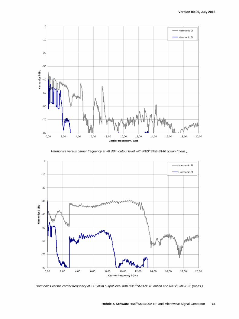
Harmonics versus carrier frequency at +8 dBm output level with R&S®SMB-B140 option (meas.).
Harmonics versus carrier frequency at +13 dBm output level with R&S®SMB-B140 option and R&S®SMB-B32 (meas.).
-80
-70
-60
-50
-40
-30
-20
-10
0
0,00 2,00 4,00 6,00 8,00 10,00 12,00 14,00 16,00 18,00 20,00
Carrier frequency / GHz
Harm
on
ics
/ d
Bc
Harmonic 2f
Harmonic 3f
-80
-70
-60
-50
-40
-30
-20
-10
0
0,00 2,00 4,00 6,00 8,00 10,00 12,00 14,00 16,00 18,00 20,00
Carrier frequency / GHz
Harm
on
ics
/ d
Bc
Harmonic 2f
Harmonic 3f

Version 09.00, July 2016
16 Rohde & Schwarz R&S®SMB100A RF and Microwave Signal Generator
Harmonics versus carrier frequency at +10 dBm output level with R&S®SMB-B140 option, R&S®SMB-B32 and R&S®SMB-B26, low harmonic filter on (meas.).
-80
-70
-60
-50
-40
-30
-20
-10
0
0,00 5,00 10,00 15,00 20,00 25,00 30,00 35,00
Carrier frequency / GHz
Harm
on
ics
/ d
Bc
Harmonic 2f
Harmonic 3f

Version 09.00, July 2016
Rohde & Schwarz R&S®SMB100A RF and Microwave Signal Generator 17
Measured SSB phase noise with R&S®SMB-B1H OCXO option for the 1/2/3/6 GHz model.
Measured SSB phase noise with R&S®SMB-B1H OCXO option for the 12.75/20/40 GHz model.
Measured SSB phase noise, f = 1 GHz, comparison with standard internal reference, R&S®SMB-B1 OCXO option, R&S®SMB-B1H OCXO option and residual phase noise.

Version 09.00, July 2016
18 Rohde & Schwarz R&S®SMB100A RF and Microwave Signal Generator
List mode settings Frequency and level pairs can be stored in a list and set in an extremely short amount of time.
Trigger mode free run automatic
full sweep single
execute one step step
Trigger source keyboard, external trigger, remote control
Max. number of stored settings 2000
Dwell time setting range 1 ms to 1 s
Dwell time setting resolution 0.1 ms
Setting time after external trigger see frequency and level data

Version 09.00, July 2016
Rohde & Schwarz R&S®SMB100A RF and Microwave Signal Generator 19
Analog modulation
Simultaneous modulation
Amplitude modulation Frequency modulation Phase modulation Pulse modulation
Amplitude modulation ()
Frequency modulation
Phase modulation
Pulse modulation ()
= compatible
= incompatible
() = compatible with limitations: No specification applies to AM distortion, AM depth error and on/off ratio with pulse modulation.
Amplitude modulation
For f ≥ 200 kHz, level setting mode auto, AM envelope within specified level range.
Modulation source internal, external, internal + external
External coupling AC, DC
AM depth setting range at high levels; modulation is clipped when
the maximum PEP is reached.
0 % to 100 %
Resolution of setting 0.1 %
AM depth (m) error fmod = 1 kHz and m < 80 %
R&S®SMB-B101/-B102/-B103/-B106
f ≤ 23.4375 MHz < (1 % of setting + 1 %)
f > 23.4375 MHz < (4 % of setting + 1 %)
R&S®SMB-B112/-B112L/-B120/-B120L/-B131/-B140/-B140L/-B140N
f > 1 MHz, PEP ≤ 15 dBm 7, 8 < (4 % of setting + 1 %)
AM distortion fmod = 1 kHz m = 30 % m = 80 %
R&S®SMB-B101/-B102/-B103/-B106
f ≤ 23.4375 MHz < 0.25 % < 0.5 %
f > 23.4375 MHz < 1.5 % < 3 %
R&S®SMB-B112/-B112L/-B120/-B120L
f > 5 MHz, PEP ≤ 15 dBm 7 < 1.5 % < 3 %
R&S®SMB-B131/-B140/-B140L/-B140N
5 MHz < f ≤ 20 GHz,
PEP ≤ 13 dBm 7
< 1.5 % < 3 %
20 GHz < f ≤ 40 GHz,
PEP ≤ 10 dBm 7, 8
< 2 % < 4 %
Modulation frequency response m = 60 %,
DC coupling: 0 Hz to 50 kHz,
AC coupling: 10 Hz to 50 kHz
< 3 dB
Synchronous φM at AM m = 30 %, fmod = 1 kHz, ± peak/2
f ≤ 20 GHz < 0.2 rad
20 GHz < f ≤ 40 GHz < 0.4 rad
Frequency bands for frequency and phase modulation
Multiplier N is used to define FM and φM specifications within this document.
Multiplier N for different frequency ranges f ≤ 23.4375 MHz 1/4
23.4375 MHz < f ≤ 46.875 MHz 1/32
46.875 MHz < f ≤ 93.75 MHz 1/16
93.75 MHz < f ≤ 187.5 MHz 1/8
187.5 MHz < f ≤ 375 MHz 1/4
375 MHz < f ≤ 750 MHz 1/2
750 MHz < f ≤ 1500 MHz 1
1500 MHz < f ≤ 3 GHz 2
3 GHz < f ≤ 6.375 GHz 4
6.375 GHz < f ≤ 12.75 GHz 8
12.75 GHz < f ≤ 25.5 GHz 16
25.5 GHz < f ≤ 40 GHz 32
7 Or maximum specified output power, whichever is lower. 8 Temperature range 0 °C to +33 °C for f > 20 GHz.
Version 09.00, July 2016
20 Rohde & Schwarz R&S®SMB100A RF and Microwave Signal Generator
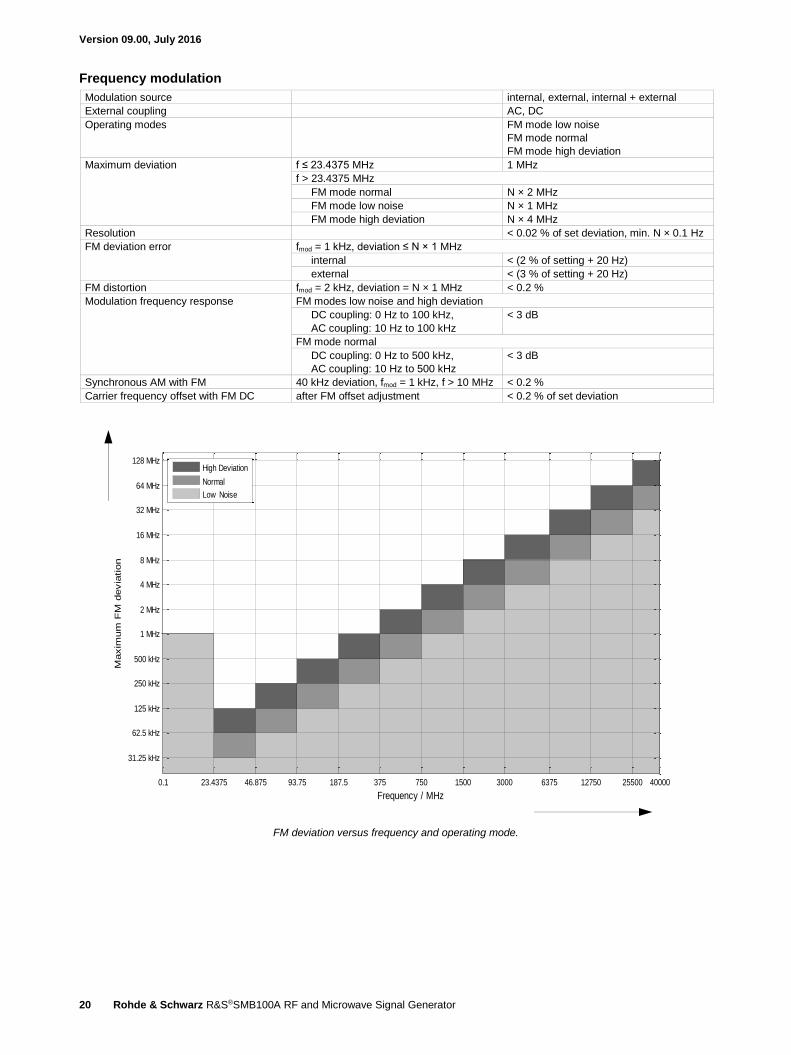
Frequency modulation
Modulation source internal, external, internal + external
External coupling AC, DC
Operating modes FM mode low noise
FM mode normal
FM mode high deviation
Maximum deviation f ≤ 23.4375 MHz 1 MHz
f > 23.4375 MHz
FM mode normal N × 2 MHz
FM mode low noise N × 1 MHz
FM mode high deviation N × 4 MHz
Resolution < 0.02 % of set deviation, min. N × 0.1 Hz
FM deviation error fmod = 1 kHz, deviation ≤ N × 1 MHz
internal < (2 % of setting + 20 Hz)
external < (3 % of setting + 20 Hz)
FM distortion fmod = 2 kHz, deviation = N × 1 MHz < 0.2 %
Modulation frequency response FM modes low noise and high deviation
DC coupling: 0 Hz to 100 kHz,
AC coupling: 10 Hz to 100 kHz
< 3 dB
FM mode normal
DC coupling: 0 Hz to 500 kHz,
AC coupling: 10 Hz to 500 kHz
< 3 dB
Synchronous AM with FM 40 kHz deviation, fmod = 1 kHz, f > 10 MHz < 0.2 %
Carrier frequency offset with FM DC after FM offset adjustment < 0.2 % of set deviation
FM deviation versus frequency and operating mode.
Maxim
um
FM
devia
tion
Frequency / MHz
0.1 23.4375 46.875 93.75 187.5 375 750 1500 3000 6375 12750 25500 40000
31.25 kHz
62.5 kHz
125 kHz
250 kHz
500 kHz
1 MHz
2 MHz
4 MHz
8 MHz
16 MHz
32 MHz
64 MHz
128 MHzHigh Deviation
Normal
Low Noise

Version 09.00, July 2016
Rohde & Schwarz R&S®SMB100A RF and Microwave Signal Generator 21
Phase modulation
Modulation source internal, external, internal + external
External coupling AC, DC
Operating modes φM modes low noise/normal/high deviation
Maximum deviation f ≤ 23.4375 MHz 2 rad
f > 23.4375 MHz
φM mode normal N × 4 rad
φM mode low noise N × 10 rad
φM mode high deviation N × 40 rad
Resolution < 0.02 % of set deviation,
min. N × 20 µrad
φM deviation error fmod = 1 kHz, deviation ≤ half of max. deviation
internal < (2 % of setting + 0.003 rad)
external < (3 % of setting + 0.003 rad)
φM distortion fmod = 10 kHz, half of max. deviation < 0.2 %
Modulation frequency response φM modes low noise and high deviation
DC coupling: 0 Hz to 100 kHz,
AC coupling: 10 Hz to 100 kHz
< 3 dB
φM mode normal
DC coupling: 0 Hz to 500 kHz,
AC coupling: 10 Hz to 500 kHz
< 3 dB
φM deviation versus frequency and operating mode.
Maxim
um
PM
devia
tion
Frequency / MHz
0.1 23.4375 46.875 93.75 187.5 375 750 1500 3000 6375 12750 25500 40000
0.125 rad
0.25 rad0.3125 rad
0.5 rad0.625 rad
1 rad1.25 rad
2 rad2.5 rad
4 rad5 rad
8 rad10 rad
16 rad20 rad
32 rad40 rad
64 rad80 rad
128 rad160 rad
320 rad
640 rad
1280 radHigh Deviation
Low Noise
Normal

Version 09.00, July 2016
22 Rohde & Schwarz R&S®SMB100A RF and Microwave Signal Generator
Pulse modulation (R&S®SMB-K21 or R&S®SMB-K22 option)
When pulse modulation is activated, the R&S®SMB100A automatically switches to ALC state S&H. In this case, the ALC loop is
opened and the output level is set directly. In order to set the correct level, a S&H measurement is performed prior to each frequency
or level setting or after switching RF on.
In the following cases, the nominal on level is present for approximately 2 ms during a S&H measurement after level or frequency
setting or after switching RF on:
No attenuator is installed (R&S®SMB-B112L/-B120L/-B140L frequency option)
A mechanical step attenuator is installed (R&S®SMB-B120/-B131/-B140/-B140N frequency option)
For instruments with electronic step attenuator (R&S®SMB-B101/-B102/-B103/-B106 or R&S®SMB-B112 frequency option), the level
during a sample and hold measurement is decreased by 30 dB:
The R&S®SMB-K21 option is available for R&S®SMB-B112/-B112L/-B120/-B120L/-B131/-B140/-B140L/-B140N
The R&S®SMB-K22 option is available for R&S®SMB-B101/-B102/-B103/-B106
Modulation source external, internal
On/off ratio level > 0 dBm for instruments without step
attenuator
> 80 dB
Rise/fall time 10 % to 90 % of RF amplitude
23.4375 MHz < f ≤ 20 GHz < 15 ns, < 5 ns (typ.)
f > 20 GHz < 15 ns, < 9 ns (typ.)
Minimum pulse width 50 %/50 % of RF amplitude
with
R&S®SMB-B101, R&S®SMB-B102,
R&S®SMB-B103, R&S®SMB-B106,
R&S®SMB-B112, R&S®SMB-B112L,
R&S®SMB-B120, R&S®SMB-B120L,
R&S®SMB-B131, R&S®SMB-B140,
R&S®SMB-B140L frequency options
20 ns
with R&S®SMB-B140N frequency option
f ≤ 20.0 GHz 20 ns
f > 20.0 GHz 30 ns
Pulse repetition frequency 0 Hz to 25 MHz
Video crosstalk for
R&S®SMB-B101/-B102/-B103/-B106
spectral line of fundamental of 100 kHz
pulse repetition frequency
< –25 dBc
Video crosstalk for
R&S®SMB-B112/-B112L/-B120/-B120L/
-B140/-B140L/-B140N
spectral line of fundamental of 100 kHz
pulse repetition frequency
< –30 dBc
Version 09.00, July 2016
Rohde & Schwarz R&S®SMB100A RF and Microwave Signal Generator 23
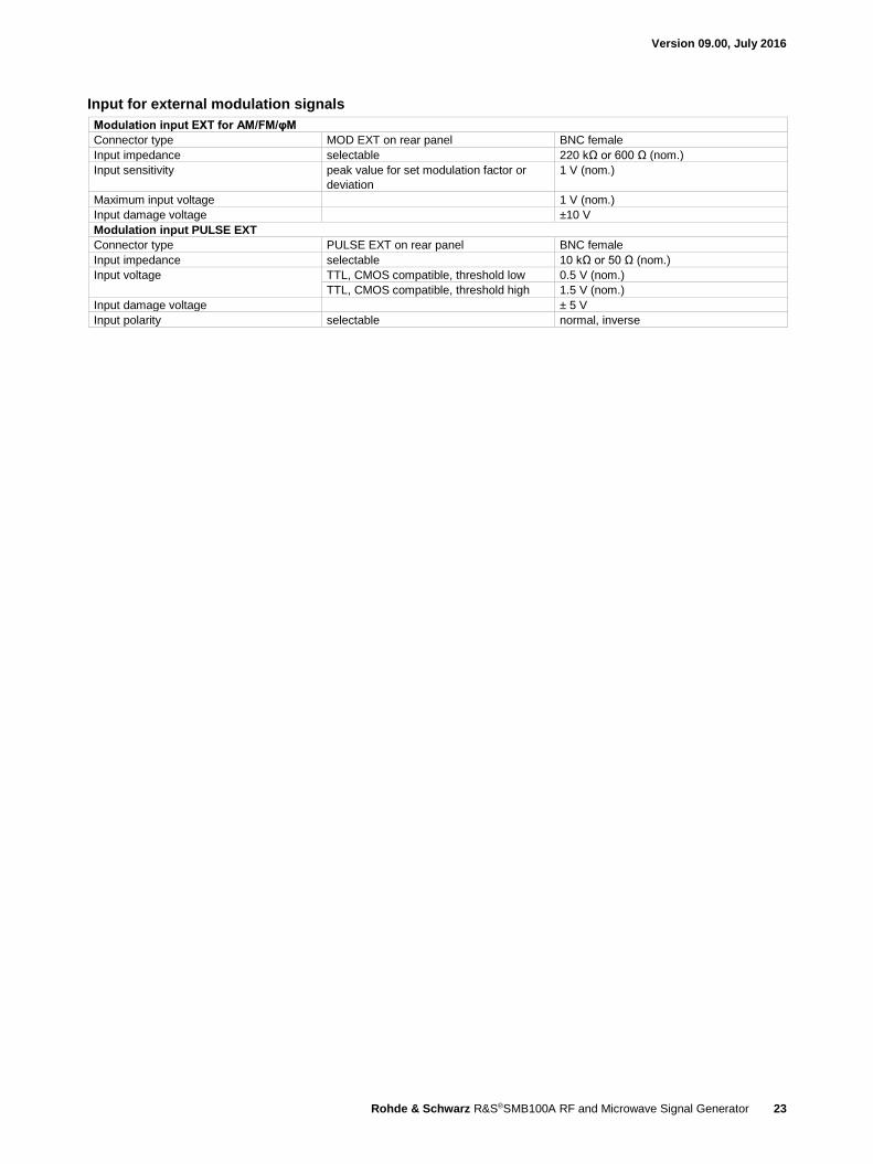
Input for external modulation signals
Modulation input EXT for AM/FM/φM
Connector type MOD EXT on rear panel BNC female
Input impedance selectable 220 kΩ or 600 Ω (nom.)
Input sensitivity peak value for set modulation factor or
deviation
1 V (nom.)
Maximum input voltage 1 V (nom.)
Input damage voltage ±10 V
Modulation input PULSE EXT
Connector type PULSE EXT on rear panel BNC female
Input impedance selectable 10 kΩ or 50 Ω (nom.)
Input voltage TTL, CMOS compatible, threshold low 0.5 V (nom.)
TTL, CMOS compatible, threshold high 1.5 V (nom.)
Input damage voltage ± 5 V
Input polarity selectable normal, inverse
Version 09.00, July 2016
24 Rohde & Schwarz R&S®SMB100A RF and Microwave Signal Generator
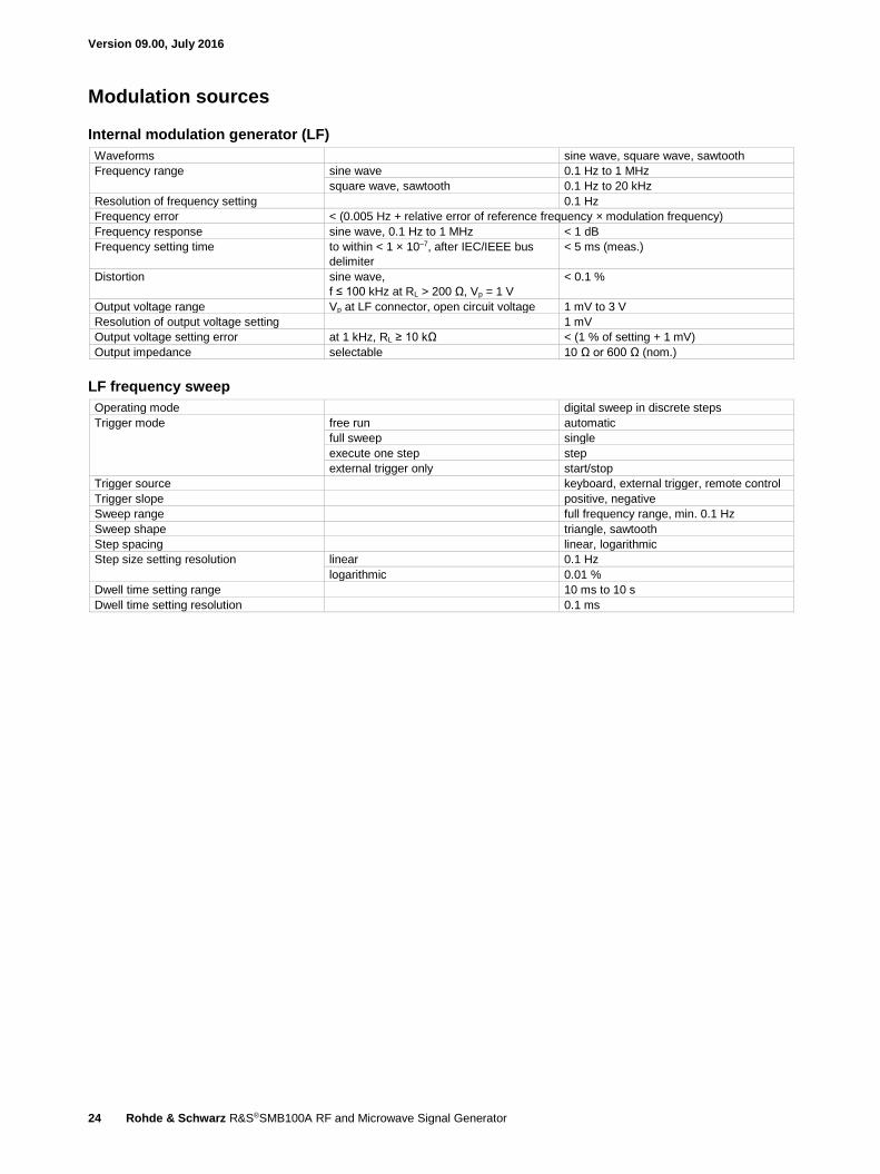
Modulation sources
Internal modulation generator (LF)
Waveforms sine wave, square wave, sawtooth
Frequency range sine wave 0.1 Hz to 1 MHz
square wave, sawtooth 0.1 Hz to 20 kHz
Resolution of frequency setting 0.1 Hz
Frequency error < (0.005 Hz + relative error of reference frequency × modulation frequency)
Frequency response sine wave, 0.1 Hz to 1 MHz < 1 dB
Frequency setting time to within < 1 × 10⁻⁷, after IEC/IEEE bus
delimiter
< 5 ms (meas.)
Distortion sine wave,
f ≤ 100 kHz at RL > 200 Ω, Vp = 1 V
< 0.1 %
Output voltage range Vp at LF connector, open circuit voltage 1 mV to 3 V
Resolution of output voltage setting 1 mV
Output voltage setting error at 1 kHz, RL ≥ 10 kΩ < (1 % of setting + 1 mV)
Output impedance selectable 10 Ω or 600 Ω (nom.)
LF frequency sweep
Operating mode digital sweep in discrete steps
Trigger mode free run automatic
full sweep single
execute one step step
external trigger only start/stop
Trigger source keyboard, external trigger, remote control
Trigger slope positive, negative
Sweep range full frequency range, min. 0.1 Hz
Sweep shape triangle, sawtooth
Step spacing linear, logarithmic
Step size setting resolution linear 0.1 Hz
logarithmic 0.01 %
Dwell time setting range 10 ms to 10 s
Dwell time setting resolution 0.1 ms

Version 09.00, July 2016
Rohde & Schwarz R&S®SMB100A RF and Microwave Signal Generator 25
Pulse generator (R&S®SMB-K23 option)
The pulse generator is fully digital; the clock is derived directly from the instrument’s reference frequency.
Pulse mode single pulse, double pulse
Trigger modes free run, internally triggered automatic
externally triggered, externally gated
Active trigger edge positive or negative
Pulse period setting range 40 ns to 85 s
Pulse period setting resolution 10 ns
Pulse width setting range pulse widths of double pulses can be set
independently
10 ns to 1 s
Pulse width setting resolution 10 ns
Pulse delay setting range with external trigger 10 ns to 1 s
Pulse delay setting resolution with external trigger 10 ns
Double-pulse spacing setting range 20 ns to 1 s
Double-pulse spacing setting resolution 10 ns
External trigger delay 50 ns (meas.)
External trigger jitter of delay < 10 ns
PULSE/VIDEO output signal without load digital signal 0 V/3.3 V (nom.)
Pulse train (R&S®SMB-K27 option)
The R&S®SMB-K27 option enhances the functionality of the pulse generator (R&S®SMB-K23 option). With this option, pulses and
pulse sequences can be user-defined, e.g. to generate jittered or staggered pulse scenarios widely used in radar applications.
Pulse modes setting of pulse width, pulse spacing and
pulse sequences
user-programmable
Trigger modes automatic (free run)
externally triggered
Active trigger edge positive or negative
Number of pulses 1 to 2047
Number of repetitions per pulse 1 to 65535
Pulse width and pulse spacing setting
range
10 ns to 5 ms
Pulse width and pulse spacing setting
resolution
10 ns
Version 09.00, July 2016
26 Rohde & Schwarz R&S®SMB100A RF and Microwave Signal Generator
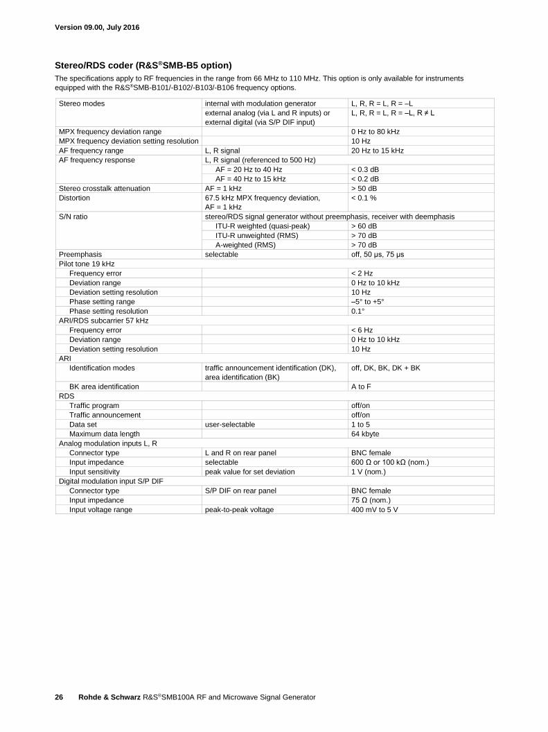
Stereo/RDS coder (R&S®SMB-B5 option)
The specifications apply to RF frequencies in the range from 66 MHz to 110 MHz. This option is only available for instruments
equipped with the R&S®SMB-B101/-B102/-B103/-B106 frequency options.
Stereo modes internal with modulation generator L, R, R = L, R = –L
external analog (via L and R inputs) or
external digital (via S/P DIF input)
L, R, R = L, R = –L, R ≠ L
MPX frequency deviation range 0 Hz to 80 kHz
MPX frequency deviation setting resolution 10 Hz
AF frequency range L, R signal 20 Hz to 15 kHz
AF frequency response L, R signal (referenced to 500 Hz)
AF = 20 Hz to 40 Hz < 0.3 dB
AF = 40 Hz to 15 kHz < 0.2 dB
Stereo crosstalk attenuation AF = 1 kHz > 50 dB
Distortion 67.5 kHz MPX frequency deviation,
AF = 1 kHz
< 0.1 %
S/N ratio stereo/RDS signal generator without preemphasis, receiver with deemphasis
ITU-R weighted (quasi-peak) > 60 dB
ITU-R unweighted (RMS) > 70 dB
A-weighted (RMS) > 70 dB
Preemphasis selectable off, 50 μs, 75 μs
Pilot tone 19 kHz
Frequency error < 2 Hz
Deviation range 0 Hz to 10 kHz
Deviation setting resolution 10 Hz
Phase setting range –5° to +5°
Phase setting resolution 0.1°
ARI/RDS subcarrier 57 kHz
Frequency error < 6 Hz
Deviation range 0 Hz to 10 kHz
Deviation setting resolution 10 Hz
ARI
Identification modes traffic announcement identification (DK),
area identification (BK)
off, DK, BK, DK + BK
BK area identification A to F
RDS
Traffic program off/on
Traffic announcement off/on
Data set user-selectable 1 to 5
Maximum data length 64 kbyte
Analog modulation inputs L, R
Connector type L and R on rear panel BNC female
Input impedance selectable 600 Ω or 100 kΩ (nom.)
Input sensitivity peak value for set deviation 1 V (nom.)
Digital modulation input S/P DIF
Connector type S/P DIF on rear panel BNC female
Input impedance 75 Ω (nom.)
Input voltage range peak-to-peak voltage 400 mV to 5 V

Version 09.00, July 2016
Rohde & Schwarz R&S®SMB100A RF and Microwave Signal Generator 27
Remote control Interfaces remote control IEC 60625 (GPIB IEEE-488.2)
Ethernet/LAN 10/100BASE-T
USB 2.0 (high speed)
serial RS-232 9
Command set SCPI 1999.5 or compatible command sets
Compatible command sets These command sets can be selected in
order to emulate another instrument.
Agilent/HP E442x
Agilent/HP E443x
Agilent/HP E8663
Agilent/HP E8257/67
Agilent/HP N51xx Analog Parts
Agilent/HP 8642
Agilent/HP 8643A
Agilent/HP 8644A/B
Agilent/HP 8645
Agilent/HP 8647A
Agilent/HP 8648A/B/C/D
Agilent/HP 8656A/B
Agilent/HP 8657A/B
Agilent/HP 8664/65
Agilent N5161A, 5181A (MXG analog)
Aeroflex/IFR 2023/2024
Aeroflex/IFR 203x, 204x, 205x
Panasonic PA8303
R&S®SML
R&S®SMT
R&S®SMY
additional command sets for instruments
equipped with R&S®SMB-B112/B112L,
R&S®SMB-B120/-B120L/-B131,
R&S®SMB-B140/-B140L/-B140N
Anritsu 68017/37
Agilent/HP 834x
Agilent/HP 8360
Agilent/HP 8362x
Agilent/HP 83630
Agilent/HP 8371x
Agilent/HP 8373x
Agilent/HP 8662/63
Agilent/HP 8673
Agilent N5183A (MXG microwave)
Agilent E8257D; 8663 B/D (PSG analog)
R&S®SMR
IEC/IEEE bus address 0 to 30
Ethernet/LAN protocols and services VISA VXI-11 (remote control)
Telnet/RawEthernet (remote control)
VNC (remote operation with web browser)
FTP (file transfer protocol)
SMB (mapping parts of the instrument to a
host file system)
Ethernet/LAN addressing DHCP, static, support of ZeroConf and
M-DNS to ease the direct connection to a
system controller
USB protocol VISA USB-TMC
9 Requires the R&S®TS-USB1 serial adapter (recommended extra).
Version 09.00, July 2016
28 Rohde & Schwarz R&S®SMB100A RF and Microwave Signal Generator
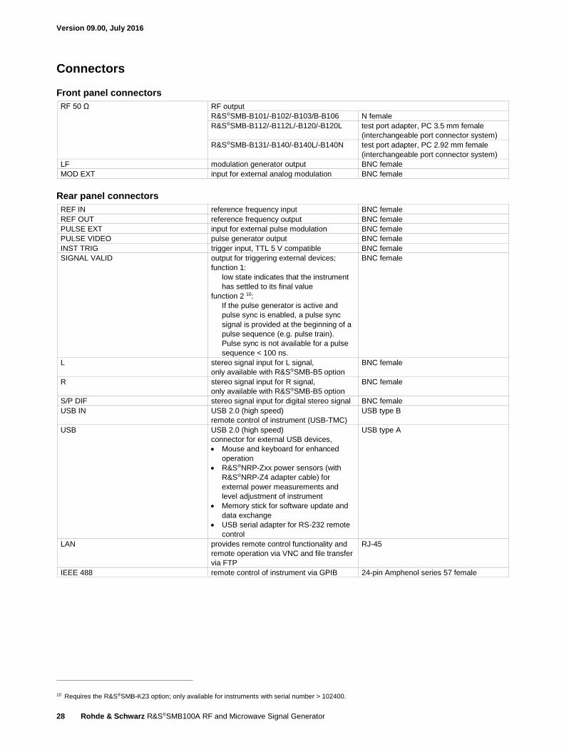
Connectors
Front panel connectors
RF 50 Ω RF output
R&S®SMB-B101/-B102/-B103/B-B106 N female
R&S®SMB-B112/-B112L/-B120/-B120L test port adapter, PC 3.5 mm female
(interchangeable port connector system)
R&S®SMB-B131/-B140/-B140L/-B140N test port adapter, PC 2.92 mm female
(interchangeable port connector system)
LF modulation generator output BNC female
MOD EXT input for external analog modulation BNC female
Rear panel connectors
REF IN reference frequency input BNC female
REF OUT reference frequency output BNC female
PULSE EXT input for external pulse modulation BNC female
PULSE VIDEO pulse generator output BNC female
INST TRIG trigger input, TTL 5 V compatible BNC female
SIGNAL VALID output for triggering external devices;
function 1:
low state indicates that the instrument
has settled to its final value
function 2 10:
If the pulse generator is active and
pulse sync is enabled, a pulse sync
signal is provided at the beginning of a
pulse sequence (e.g. pulse train).
Pulse sync is not available for a pulse
sequence < 100 ns.
BNC female
L stereo signal input for L signal,
only available with R&S®SMB-B5 option
BNC female
R stereo signal input for R signal,
only available with R&S®SMB-B5 option
BNC female
S/P DIF stereo signal input for digital stereo signal BNC female
USB IN USB 2.0 (high speed)
remote control of instrument (USB-TMC)
USB type B
USB USB 2.0 (high speed)
connector for external USB devices,
Mouse and keyboard for enhanced
operation
R&S®NRP-Zxx power sensors (with
R&S®NRP-Z4 adapter cable) for
external power measurements and
level adjustment of instrument
Memory stick for software update and
data exchange
USB serial adapter for RS-232 remote
control
USB type A
LAN provides remote control functionality and
remote operation via VNC and file transfer
via FTP
RJ-45
IEEE 488 remote control of instrument via GPIB 24-pin Amphenol series 57 female
10 Requires the R&S®SMB-K23 option; only available for instruments with serial number > 102400.
Version 09.00, July 2016
Rohde & Schwarz R&S®SMB100A RF and Microwave Signal Generator 29
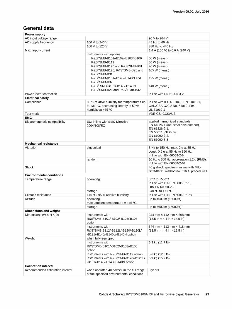
General data Power supply
AC input voltage range 90 V to 264 V
AC supply frequency 100 V to 240 V 45 Hz to 66 Hz
100 V to 120 V 380 Hz to 440 Hz
Max. input current 1.4 A (100 V) to 0.6 A (240 V)
instruments with options
R&S®SMB-B101/-B102/-B103/-B106 60 W (meas.)
R&S®SMB-B112 80 W (meas.)
R&S®SMB-B120 and R&S®SMB-B31 90 W (meas.)
R&S®SMB-B120, R&S®SMB-B25 and
R&S®SMB-B31
105 W (meas.)
R&S®SMB-B131/-B140/-B140N and
R&S®SMB-B32
125 W (meas.)
R&S® SMB-B131/-B140/-B140N,
R&S®SMB-B26 and R&S®SMB-B32
140 W (meas.)
Power factor correction in line with EN 61000-3-2
Electrical safety
Compliance 80 % relative humidity for temperatures up
to +31 °C, decreasing linearly to 50 %
humidity at +55 °C
in line with IEC 61010-1, EN 61010-1,
CAN/CSA-C22.2 No. 61010-1-04,
UL 61010-1
Test mark VDE-GS, CCSAUS
EMC
Electromagnetic compatibility EU: in line with EMC Directive
2004/108/EC
applied harmonized standards: EN 61326-1 (industrial environment), EN 61326-2-1, EN 55011 (class B), EN 61000-3-2,
EN 61000-3-3
Mechanical resistance
Vibration sinusoidal 5 Hz to 150 Hz, max. 2 g at 55 Hz,
const. 0.5 g at 55 Hz to 150 Hz,
in line with EN 60068-2-6
random 10 Hz to 300 Hz, acceleration 1.2 g (RMS),
in line with EN 60068-2-64
Shock 40 g shock spectrum, in line with MIL-
STD-810E, method no. 516.4, procedure I
Environmental conditions
Temperature range operating 0 °C to +55 °C
in line with DIN EN 60068-2-1,
DIN EN 60068-2-2
storage –40 °C to +71 °C
Climatic resistance +40 °C, 95 % relative humidity in line with DIN EN 60068-2-78
Altitude operating,
max. ambient temperature = +45 °C
up to 4600 m (15000 ft)
storage up to 4600 m (15000 ft)
Dimensions and weight
Dimensions (W × H × D) instruments with
R&S®SMB-B101/-B102/-B103/-B106
option
344 mm × 112 mm × 368 mm
(13.5 in × 4.4 in × 14.5 in)
instruments with
R&S®SMB-B112/-B112L/-B120/-B120L/
-B131/-B140/-B140L/-B140N option
344 mm × 112 mm × 418 mm
(13.5 in × 4.4 in × 16.5 in)
Weight when fully equipped
instruments with
R&S®SMB-B101/-B102/-B103/-B106
option
5.3 kg (11.7 lb)
instruments with R&S®SMB-B112 option 5.6 kg (12.3 lb)
instruments with R&S®SMB-B120/-B120L/
-B131/-B140/-B140/-B140N option
6.9 kg (15.2 lb)
Calibration interval
Recommended calibration interval when operated 40 h/week in the full range
of the specified environmental conditions
3 years

Version 09.00, July 2016
30 Rohde & Schwarz R&S®SMB100A RF and Microwave Signal Generator
Ordering information Designation Type Order No.
Base unit
RF and Microwave Signal Generator 11 R&S®SMB100A 1406.6000.02
Including power cable, quick start guide and CD-ROM (with operating and service manual)
Options
RF path/frequency option
9 kHz to 1.1 GHz R&S®SMB-B101 1407.2509.02
9 kHz to 2.2 GHz R&S®SMB-B102 1407.2609.02
9 kHz to 3.2 GHz R&S®SMB-B103 1407.2709.02
9 kHz to 6 GHz R&S®SMB-B106 1407.2909.02
100 kHz to 12.75 GHz, with electronic step attenuator R&S®SMB-B112 1407.2109.02
100 kHz to 12.75 GHz, without step attenuator R&S®SMB-B112L 1407.2150.02
100 kHz to 20 GHz, with mechanical step attenuator R&S®SMB-B120 1407.2209.02
100 kHz to 20 GHz, without step attenuator R&S®SMB-B120L 1407.2250.02
100 kHz to 31.8 GHz, with mechanical step attenuator R&S®SMB-B131 1407.2280.02
100 kHz to 40 GHz, with mechanical step attenuator R&S®SMB-B140 1407.2309.02
100 kHz to 40 GHz, without step attenuator R&S®SMB-B140L 1407.2350.02
100 kHz to 40 GHz, with mechanical step attenuator,
minimum pulse width limited
R&S®SMB-B140N 1407.2380.02
OCXO Reference Oscillator 12 R&S®SMB-B1 1407.3005.02
OCXO Reference Oscillator, High Performance 12 R&S®SMB-B1H 1407.3070.02
Stereo/RDS Coder 13 R&S®SMB-B5 1407.3205.02
Harmonic filter option
150 MHz to 20 GHz
(only available with R&S®SMB-B120/-B120L)
R&S®SMB-B25 1407.1660.02
150 MHz to 40 GHz
(only available with R&S®SMB-B131/-B140/-B140L/-B140N)
R&S®SMB-B26 1407.1760.02
Reverse Power Protection
(only available with R&S®SMB-B112, R&S®SMB-B112L)
R&S®SMB-B30 1407.1160.02
High-power option
50 MHz to 20 GHz
(only available with R&S®SMB-B120/-B120L)
R&S®SMB-B31 1407.1260.02
50 MHz to 40 GHz
(only available with R&S® SMB-B131/-B140/-B140L/-B140N)
R&S®SMB-B32 1407.1360.02
Pulse Modulator,
for R&S®SMB-B112/-B112L/-B120/-B120L/-B131/-B140/-B140L/-B140N
R&S®SMB-K21 1407.3811.02
Pulse Modulator, for R&S®SMB-B101/-B102/-B103/-B106 R&S®SMB-K22 1407.3770.02
Pulse Generator R&S®SMB-K23 1407.3786.02
Pulse Train 14 R&S®SMB-K27 1407.3828.02
Recommended extras
19" Rack Adapter R&S®ZZA-S234 1109.4493.00
Power Sensor, 9 kHz to 6 GHz, for levels up to 33 dBm; incl. USB adapter cable R&S®NRP-Z92 1171.7005.42
Power Sensor, DC to 40 GHz, for levels up to 20 dBm R&S®NRP-Z55 1138.2008.03
Power Sensor, 10 MHz to 18 GHz, for levels up to 33 dBm R&S®NRP-Z22 1137.7506.02
USB Adapter for R&S®NRP-Zxx power sensors R&S®NRP-Z4 1146.8001.02
USB Serial Adapter for RS-232 remote control R&S®TS-USB1 6124.2531.00
Adapters for instruments with an R&S®SMB-B112/-B112L/-B120/-B120L frequency option
Test port adapter, PC 3.5 mm female 1021.0512.00
Test port adapter, PC 3.5 mm male 1021.0529.00
Test port adapter, N female 1021.0535.00
Test port adapter, N male 1021.0541.00
Adapters for instruments with an R&S®SMB-B131/-B140/-B140L/-B140N frequency option
Test port adapter, 2.4 mm female 1088.1627.02
Test port adapter, 2.92 mm female 1036.4790.00
Test port adapter, 2.92 male 1036.4802.00
Test port adapter, N female 1036.4777.00
Test port adapter, N male 1036.4783.00
11 The base unit must be ordered together with an R&S®SMB-B101/-B102/-B103/-B106/-B112/-B112L/-B120/-B120L/-B131/-B140/-B140L/-B140N
frequency option. 12 Only one of the R&S®SMB-B1 or R&S®SMB-B1H option can be installed. 13 Only available with an R&S®SMB-B101, R&S®SMB-B102, R&S®SMB-B103 or R&S®SMB-B106 frequency option. 14 Requires the R&S®SMB-K23 option; only available for instruments with serial number > 102400.
Version 09.00, July 2016
Rohde & Schwarz R&S®SMB100A RF and Microwave Signal Generator 31
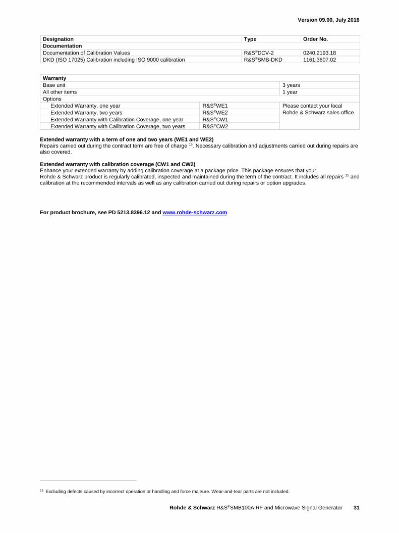
Designation Type Order No.
Documentation
Documentation of Calibration Values R&S®DCV-2 0240.2193.18
DKD (ISO 17025) Calibration including ISO 9000 calibration R&S®SMB-DKD 1161.3607.02
Warranty
Base unit 3 years
All other items 1 year
Options
Extended Warranty, one year R&S®WE1 Please contact your local
Rohde & Schwarz sales office. Extended Warranty, two years R&S®WE2
Extended Warranty with Calibration Coverage, one year R&S®CW1
Extended Warranty with Calibration Coverage, two years R&S®CW2
Extended warranty with a term of one and two years (WE1 and WE2) Repairs carried out during the contract term are free of charge 15. Necessary calibration and adjustments carried out during repairs are also covered. Extended warranty with calibration coverage (CW1 and CW2) Enhance your extended warranty by adding calibration coverage at a package price. This package ensures that your Rohde & Schwarz product is regularly calibrated, inspected and maintained during the term of the contract. It includes all repairs 15 and calibration at the recommended intervals as well as any calibration carried out during repairs or option upgrades.
For product brochure, see PD 5213.8396.12 and www.rohde-schwarz.com
15 Excluding defects caused by incorrect operation or handling and force majeure. Wear-and-tear parts are not included.

R&S® is a registered trademark of Rohde & Schwarz GmbH & Co. KG
Trade names are trademarks of the owners
PD 5213.8396.22 | Version 09.00 | July 2016 (as)
R&S®SMB100A RF and Microwave Signal Generator
Data without tolerance limits is not binding | Subject to change
© 2008 - 2016 Rohde & Schwarz GmbH & Co. KG | 81671 Munich, Germany
Service that adds value Worldwide Local and personalized Customized and flexible Uncompromising quality Long-term dependability
5213
.839
6.22
09.
00 P
DP
1 e
n
About Rohde & SchwarzThe Rohde & Schwarz electronics group offers innovative solutions in the following business fields: test and mea-surement, broadcast and media, secure communications, cybersecurity, radiomonitoring and radiolocation. Founded more than 80 years ago, the independent company which is headquartered in Munich, Germany, has an extensive sales and service network with locations in more than 70 countries.
Sustainable product design Environmental compatibility and eco-footprint Energy efficiency and low emissions Longevity and optimized total cost of ownership
Certified Environmental Management
ISO 14001Certified Quality Management
ISO 9001
Regional contact Europe, Africa, Middle East | +49 89 4129 12345 [email protected]
North America | 1 888 TEST RSA (1 888 837 87 72) [email protected]
Latin America | +1 410 910 79 88 [email protected]
Asia Pacific | +65 65 13 04 88 [email protected]
China | +86 800 810 82 28 | +86 400 650 58 96 [email protected]
Rohde & Schwarz GmbH & Co. KGwww.rohde-schwarz.com
Rohde & Schwarz trainingwww.training.rohde-schwarz.com
5213839622
SMB100A_dat-sw_en_5213-8396-22_v0900_cover.indd 2 14.07.2016 19:10:02