Embed Size (px)
Citation preview

Te
st &
Mea
sure
men
t
Prod
uct B
roch
ure
| 05.
00R&S®SMB100ARF and Microwave Signal GeneratorVersatile, compact, up to 40 GHz;110 GHz with upconverter
SMB100A_bro_en_5213_8396_12.indd 1 13.05.2013 12:48:38

2
The compact, versatile R&S®SMB100A RF and microwave signal generator with a frequency range up to 40 GHz provides outstanding spectral purity and high output power. In addition, it features easy operation, comprehensive functionality and low cost of ownership.
R&S®SMB100A RF and Microwave Signal GeneratorAt a glance
Furthermore, the R&S®SMB100A can be ideally used for measuring the blocking characteristic up to a CW frequencyof12.75 GHz,asspecifiedinvarioustelecom-munications standards. When it comes to frequently changinglevelsettings,thisisthefirsttimethatawear-free electronic step attenuator is used in this frequency range.
Twofrequencyoptionsupto20 GHzand40 GHzareavail-abletocoverthemicrowaverange.Theseoptionsaresuit-able for tests on radar systems and antennas in the X and Kbands,forexampleforwidebandreceivertests.
Forevenhigherfrequencies,thefrequencyrangeoftheR&S®SMB100AcanbeeasilyextendedwiththeR&S®SMZfrequencymultiplier.TheR&S®SMB100AplusR&S®SMZsolutioncombineseasyhandlingwithprecise,adjustableoutputlevelsinthefrequencyrangefrom50 GHzto110 GHz.
In addition to pure CW signals, the R&S®SMB100A also providesthemostcommonanalogAMandFM/φMmod-ulationmodesasstandard.Moreover,theR&S®SMB100Acanbeequippedwithanexcellentpulsegeneratorandpulse modulator that makes it possible to generate user-programmable pulse scenarios, also referred to as pulse trains.
Key facts ❙ Widefrequencyrangefrom9 kHzto6 GHzorfrom100 kHzto40 GHz
❙ ExcellentsignalcharacteristicswithlowSSBphasenoiseoftyp.–128 dBc(at1 GHz,20 kHzoffset)
❙ Highoutputpoweroftyp.upto+27 dBm ❙ AllimportantanalogmodulationswithAM,FM/φMandpulse modulation supported
❙ Compactsizewithonlytwoheightunitsandlowweight
TheR&S®SMB100AprovidesRFandmicrowavechar-acteristics that are exceptional in its class, making it an excellent general-purpose instrument. These outstanding characteristicsplusitscompactsizeandlowweightmaketheinstrumentidealforawiderangeofapplications.TheR&S®SMB100Aisoptimallysuitedforuseindevelopment,productionandservice,or,toputitevensimpler:whereverananalogRFormicrowavesignalisrequired.
Itswidefrequencyrangecoversalargenumberofchal-lenging applications. The R&S®SMB100A is the perfect choice for applications in the important ISM bands up to 5.7 GHzaswellasforEMCapplicationsbecauseofitslowerfrequencylimitof9 kHz.
SMB100A_bro_en_5213_8396_12.indd 2 13.05.2013 12:48:41

Rohde & Schwarz R&S®SMB100ARFandMicrowaveSignalGenerator3
R&S®SMB100A RF and Microwave Signal GeneratorBenefits and key features
All-purpose signal source ❙ Widefrequencyrangefrom9 kHzto1.1/2.2/3.2/6 GHzorfrom100 kHzto12.75/20/40 GHzcoveringthemainfrequencybandsforRFandmicrowaveapplications
❙ Frequencyextensionfrom50 GHzto110 GHzincombinationwiththeR&S®SMZfrequencymultiplier
❙ AllimportantanalogmodulationswithAM,FM/φMandpulse modulation supported
❙ SupportofR&S®NRP-Zxxpowersensors ❙ Reversepowerprotectionforhighoperationalreliabilityincludedasstandardinthemodelsupto6 GHz(optionallyavailableforthe12.75 GHzmodel)
❙ Intuitiveuserinterfacewithgraphicaldisplayofsignalflowforeasyoperation
❙ RemotecontrolviaLAN,USBandGPIBincludingemulation modes for legacy instruments
❙ Lowweightandcompactdesignforawiderangeofapplications, including mobile applications ▷ page 5
Best signal quality in the mid-range ❙ VerylowSSBphasenoiseoftyp.–128 dBcat1 GHzandtyp.–108 dBcat10 GHzcarrierfrequency (20 kHzcarrieroffset,1 Hzmeasurementbandwidth)
❙ Optionalinternallowharmonicfiltersforthe20 GHzand40 GHzmodeltolowertheharmonicstolessthan–50 dBcforfrequenciesabove150 MHz
❙ InnovativeDDS-basedsynthesizerconcept ▷ page 8
High output power and wide level range ❙ Highpoweroverawidefrequencyrange ❙ Lowlevelrangedownto–120 dBm(forinstrumentsequippedwithstepattenuator)withnocompromiseinquality
❙ Highharmonicssuppressionof<–30 dBcevenathighoutputpower ▷ page 10
Ideal for production ❙ Wear-freeelectronicattenuatorupto12.75 GHzensuringlonglifeeveninthecaseofheavyuseinproduction
❙ Highlevelaccuracyandrepeatabilityforhighproductionyield
❙ ClosedlooppowercontrolensureshighlyaccurateandverystableinputpowertotheDUTirrespectiveofunwantedpowerdriftsinthetestsetup(e.g.causedbyapoweramplifierinbetweenthesignalgeneratorandtheDUT)
❙ ShortfrequencyandlevelsettingtimeswhichcanbefurtherreducedinListmode
❙ Lowpowerconsumption ▷ page 12
SMB100A_bro_en_5213_8396_12.indd 3 13.05.2013 12:48:41

4
Ready for aerospace and defense applications ❙ Optionalpulsemodulatorwithtyp.>90 dBON/OFFratioandrise/falltimeoftyp.<5nsandpulsegeneratorwithminimumpulsewidthof10nsforradarsystemtesting
❙ Flexible generation of pulse trains for simulating complex pulsescenarios(optional)
❙ Widetemperaturerangeof0°Cto+55°Candhighpermissibleoperatingaltitudeof4600mforuseeven under extreme conditions
❙ Sanitizingofuserdataforsecuredareas ❙ High-qualityshielding ▷ page16
Flexible service concept ❙ Servicingon-siteorataRohde&Schwarzservicecenter ❙ Built-in selftest of modules to support troubleshooting ❙ Completecalibrationrecommendedonlyeverythreeyears ▷ page 20
Model overviewFrequency range 9 kHz to
1.1 GHz9 kHz to 2.2 GHz
9 kHz to 3.2 GHz
9 kHz to 6 GHz
100 kHz to 12.75 GHz
100 kHz to 20 GHz
100 kHz to 40 GHz
With electronic step attenuator ● ● ● ● ○ – –
Without electronic step attenuator – – – – ○ – –
With mechanical step attenuator – – – – – ○ ○
Without mechanical step attenuator – – – – – ○ ○
Highpower ● ● ● ● ● ○ ○
Lowharmonicfilter – – – – – ○ ○
OCXO reference oscillator 1) ○ ○ ○ ○ ○ ○ ○
OCXO reference oscillator, high performance 1)
○ ○ ○ ○ ○ ○ ○
Reversepowerprotection ● ● ● ● ○ – –
Stereo/RDScoder ○ ○ ○ ○ – – –
Pulse modulator ○ ○ ○ ○ ○ ○ ○
Pulse generator ○ ○ ○ ○ ○ ○ ○
Pulse train ○ ○ ○ ○ ○ ○ ○
TheR&S®SMB100A(20 GHzor40 GHzmodel)incombinationwithoneoftheR&S®SMZfrequencymultipliersbelowcoversthefrequencyrangefrom
50 GHzupto110 GHz
Model overviewFrequency multiplier R&S®SMZ75 R&S®SMZ90 R&S®SMZ110Frequency range 50 GHzto75 GHz 60 GHzto90 GHz 75 GHzto110 GHz
With mechanically controlled attenuator 2) ○ ○ ○
With electronically controlled attenuator2) ○ ○ ○
● Standard○ Optional– Notavailable
1) Onlyoneofthefollowingoptionscanbeinstalled:R&S®SMB-B1(OCXOreferenceoscillator)orR&S®SMB-B1H(OCXOreferenceoscillator,highperformance).2) Onlyoneofthefollowingoptionscanbeinstalled:themechanicallyortheelectronicallycontrolledattenuator.
HardwareandsoftwareoptionconceptfortheR&S®SMB100A.
Thetableprovidesanoverviewofthefrequencyrangesaswellasoffunctionalitiesandoptions.
Testing of FM stereo and RDS receivers ❙ Optionalstereo/RDScoderforthe1.1/2.2/3.2/6 GHzmodels
❙ AutomaticsynchronizationofmeasurementresultswiththeR&S®UPVorR&S®UPPaudioanalyzer
❙ UptofivedifferentRDSsequenceswithupto64000 characterseach
❙ InternalLFgeneratordeliveringsinusoidalsignalsatfixedorsweptLFfrequencies ▷ page14
SMB100A_bro_en_5213_8396_12.indd 4 13.05.2013 12:48:41
Rohde & Schwarz R&S®SMB100ARFandMicrowaveSignalGenerator5
All-purpose signal source
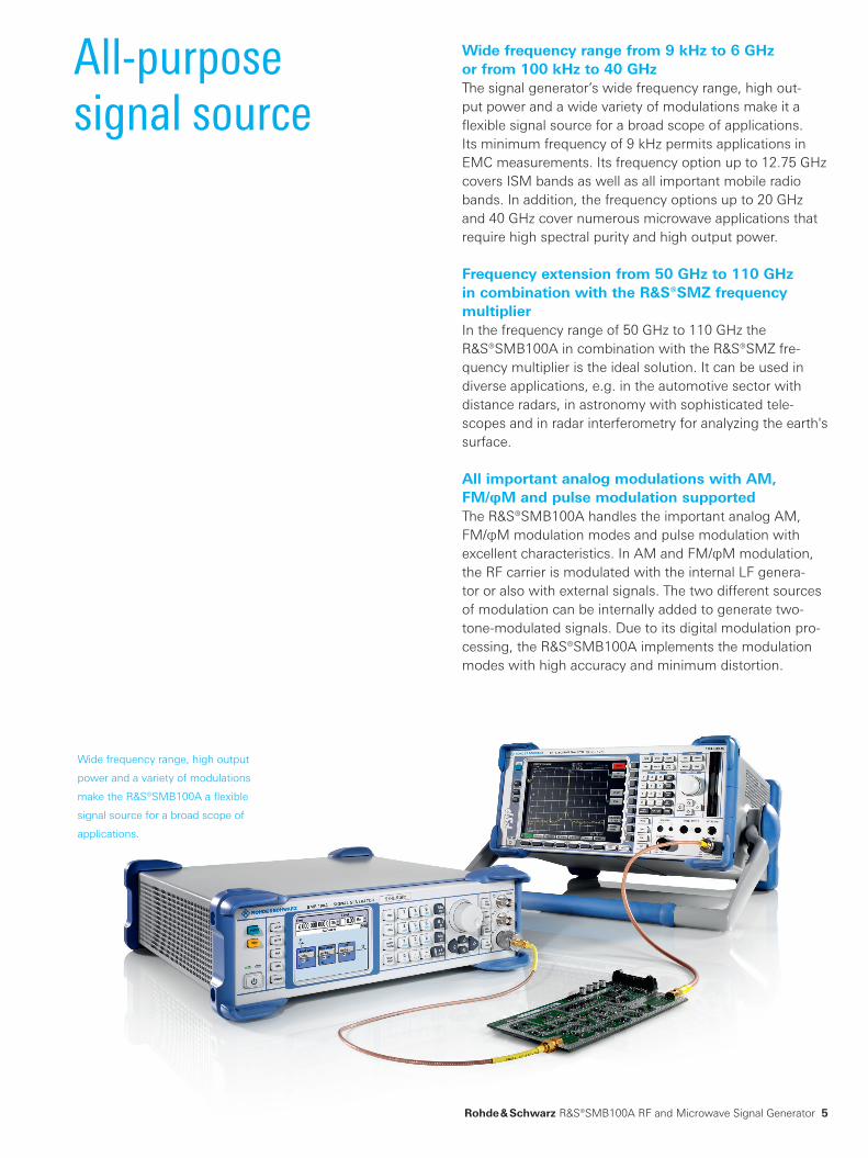
Wide frequency range from 9 kHz to 6 GHz or from 100 kHz to 40 GHzThesignalgenerator’swidefrequencyrange,highout-putpowerandawidevarietyofmodulationsmakeita flexible signal source for a broad scope of applications. Itsminimumfrequencyof9 kHzpermitsapplicationsinEMCmeasurements.Itsfrequencyoptionupto12.75 GHzcoversISMbandsaswellasallimportantmobileradiobands.Inaddition,thefrequencyoptionsupto20 GHzand40 GHzcovernumerousmicrowaveapplicationsthatrequirehighspectralpurityandhighoutputpower.
Frequency extension from 50 GHz to 110 GHz in combination with the R&S®SMZ frequency multiplierInthefrequencyrangeof50 GHzto110 GHztheR&S®SMB100AincombinationwiththeR&S®SMZfre-quency multiplier is the ideal solution. It can be used in diverseapplications,e.g.intheautomotivesectorwithdistanceradars,inastronomywithsophisticatedtele-scopesandinradarinterferometryforanalyzingtheearth'ssurface.
All important analog modulations with AM, FM/φM and pulse modulation supportedThe R&S®SMB100A handles the important analog AM, FM/φMmodulationmodesandpulsemodulationwithexcellentcharacteristics.InAMandFM/φMmodulation,theRFcarrierismodulatedwiththeinternalLFgenera-tororalsowithexternalsignals.Thetwodifferentsourcesofmodulationcanbeinternallyaddedtogeneratetwo-tone-modulatedsignals.Duetoitsdigitalmodulationpro-cessing, the R&S®SMB100A implements the modulation modeswithhighaccuracyandminimumdistortion.
Wide frequency range, high output
powerandavarietyofmodulations
make the R&S®SMB100A a flexible
signal source for a broad scope of
applications.
SMB100A_bro_en_5213_8396_12.indd 5 13.05.2013 12:48:44

6
Support of R&S®NRP-Zxx power sensorsTheR&S®SMB100AsupportsawidevarietyofR&S®NRP-ZxxUSBpowersensors.TheR&S®NRP-Z92isapowersensorthatideallycomplementsthefrequencyandlevelrangeofthegeneratorupto6 GHz.Equippedwithsuchapowersensor,theR&S®SMB100Afullyauto-maticallyperformsexternallevelcorrectionorpreciselymeasuresthepowerinthetestsetup.TheR&S®NRP-Z55powersensorcanbeusedwiththe12.75 GHz,20 GHzor40 GHzfrequencyoptionoftheR&S®SMB100Aforthesame purpose.
Reverse power protection for high operational reliabilityThestandardreversepowerprotectionforinstrumentsupto6 GHzprotectstheR&S®SMB100Afromhighexter-nalvoltagesandhighpowerattheRFoutput.Thisfea-tureshieldstheRFoutputagainstunwantedhighreversepowerandensuresahighdegreeofoperationalreliability.TheR&S®SMB-B30reversepowerprotectionisavailablefortheR&S®SMB-B112/R&S®SMB-B112L12.75 GHz frequency options.
DetailsofthemeasurementwiththeR&S®NRP-Z85
widebandpowersensor(peakandaverage).
Pulse-modulatedsignalmeasuredwiththe
R&S®NRP-Z85widebandpowersensor.
TheR&S®SMB100Awithconnected
R&S®NRP-Z92powersensorperforms
automaticlevelcorrection.
SMB100A_bro_en_5213_8396_12.indd 6 13.05.2013 12:48:45

Rohde & Schwarz R&S®SMB100ARFandMicrowaveSignalGenerator7
Intuitive user interfaceIntuitiveoperationviathegraphicaluserinterfaceandtheintegrated help system facilitate the optimum use of the R&S®SMB100A for the application at hand. To support graphicaloperation,amousecanbeconnectedviaUSB.
Remote control via LAN, USB and GPIB including emulation modesTheR&S®SMB100Aisalsoideallyequippedwithregardtotheremotecontrolinterface.InadditiontoconventionalGPIB,italsosupportsLANandUSBasstandard.ThisisespeciallyadvantageousinenvironmentssuchasservicelabswherethereisoftennoGPIB.
Signalgeneratorsareoftenusedinautomatedtestenvi-ronments. Replacing them, e.g. due to malfunctions or standard replacement procedures, requires special care. The replacement part and the replaced part must be com-patible at least in terms of electrical features and remote controlfeatures.Legacyinstrumentsoftenuseapropri-etaryremotecontrollanguage.Directreplacementthere-forerequireslanguageemulationcapabilityinthesoftwareof the replacement part. To meet these requirements, the R&S®SMB100Asignalgeneratorcomeswithalanguageemulation feature. By selecting the desired language emu-lation, the signal generator acts as the original replaced instrument. The language list already includes a large numberofemulatedinstrumentsandwillbeupdatedonaregular basis.
Low weight and compact designTheR&S®SMB100Ahasacompactsizeofonlytwoheightunitsand¾19"width.Thisformfactorplusitslowweightofmax.5.6kgforthe6 GHzmodeland6.9kgforthe40 GHzmodelmakeitidealformobileuse.Iteasilyfitsinanylabandservicecenter,wherespaceisoftenatapremium.
The emulation mode can be set in the remote setup menu of the
R&S®SMB100A.
SMB100A_bro_en_5213_8396_12.indd 7 13.05.2013 12:48:45

SSB phase noise
–160
–150
–140
–130
–120
–110
–100
–90
–80
–70
–60
–50
–40
–30
1 10 100 1 k 10 k 100 k 1 M 10 M 100 M
SSB
phas
e no
ise
in d
Bc (1
Hz)
Frequency offset in Hz
40 GHz
20 GHz
10 GHz
6 GHz
3 GHz
1 GHz
100 MHz
10 MHz
6 GHz
3 GHz
1 GHz
100 MHz
10 MHz
10 GHz
20 GHz
40 GHz
SSB phase noise
–160
–150
–140
–130
–120
–110
–100
–90
–80
–70
–60
–50
–40
–30
SSB
phas
e no
ise
in d
Bc (1
Hz)
Frequency offset in Hz
6 GHz
3 GHz
1 GHz
100 MHz
10 MHz
6 GHz
3 GHz
1 GHz
100 MHz
10 MHz
1 10 100 1 k 10 k 100 k 1 M 10 M 100 M
8
Very low SSB phase noiseWhen it comes to SSB phase noise performance, the R&S®SMB100Aconsistentlyachievesexcellentvaluesovertheentirefrequencyrangefrom9 kHzto6 GHzorfrom100 kHzto40 GHz.Thisisduetoitsremarkablecon-cept.Below3 GHz,theR&S®SMB100Aworksdownto23.3475 MHzwithfrequencydividers.Belowthisvalue,theintegratedDDSsynthesizergeneratestheoutputsig-naldirectly.Incontrasttoconventionaldesignsthatuseamixerrangebelowapprox.250 MHz,theinnovativeRohde&Schwarzsolutionleadstoamuchbetterphasenoiseperformanceatlowfrequencies.
The R&S®SMB100A is therefore the ideal replacement in test circuits for fixed-frequency high-end crystal oscillators that are often used as a reference signal. The R&S®SMB100Acombinesequalorevenimprovedsignalperformancewithadjustablefrequencyandadjustablelevel,whichishighlybeneficialasitcanbeideallyadaptedtotheDUT.Moreover,theR&S®SMB100Amakesitpos-sibletodefinetheDUTtolerancerangerelativetothereferencebyvaryingtheseparameters.
Best signal quality in the mid-range
MeasuredSSBphasenoisewiththeR&S®SMB-B1HOCXO
optionforthe12.75/20/40GHzmodel.
MeasuredSSBphasenoisewiththeR&S®SMB-B1HOCXO
optionforthe1/2/3/6GHzmodel.
Phasenoise,harmonics,nonharmonicspuriousandwide-bandnoisearekeyparameterswhenitcomestocharac-terizingthespectralpropertiesofanalogsignalgenera-tors. Many measurements focus on more than one aspect simultaneously. For example, in blocking measurements, nonharmonicstogetherwithphasenoiseareessentialingeneratingtheusuallyunwantedRFIpowerintheadja-cent channel.
SMB100A_bro_en_5213_8396_12.indd 8 13.05.2013 12:48:45

SSB phase noise
–160
–150
–140
–130
–120
–110
–100
–90
–80
–70
–60
–50
–40
–30
–20
–10
1 10 100 1 k 10 k 100 k 1 M 10 M
Frequency offset in Hz
SSB
phas
e no
ise
in d
Bc (1
Hz)
Standard (f = 1 GHz)
R&S®SMB-B1 (f = 1 GHz)
R&S®SMB-B1H (f = 1 GHz)
Residual (f = 1 GHz)
SSB phase noise
0.00 5.00 15.0010.00 20.00 30.0025.00 35.00Carrier frequency in GHz
Harm
onic
s in
dBc
–10
–20
–30
–40
–50
–60
–70
–80
Harmonic 2fHarmonic 3f
Rohde & Schwarz R&S®SMB100ARFandMicrowaveSignalGenerator9
MeasuredSSBphasenoisewithstandardreference,the
R&S®SMB-B1optionandtheR&S®SMB-B1Hoption.
Harmonicsversuscarrierfrequencyat+10 dBmoutputlevel
withR&S®SMB-B140optionandR&S®SMB-B32(meas.).
Another critical application is the total harmonic distortion (THD)measurementofapoweramplifier.Thesetupcom-prises a signal generator generating the input signal, the DUTandaspectrumanalyzerformeasuringtheamplifierperformance.Here,theharmonicsmustbelowenoughtoensurethattheharmonicdistortionofthedeviceundertest is measured and not the harmonics of the signal source.Andlastbutnotleast:forscalarnetworkanalysis,gooddynamicrangeoftheoverallsetupisessential.Badharmonicsfromthesignalsourcewilllimitthis,sincetheharmonics are unintentionally measured, too.
Innovative DDS-based synthesizer conceptThe R&S®SMB100A superbly handles high signal-quality requirements.DuetoitsinnovativeDDS-basedsynthesizerconcept,theR&S®SMB100Ayieldsunsurpassedvaluesinall parameters called for in the mid-range, thereby setting newstandards.
Tofurtherimprovetheclose-inphasenoiseandfrequencystability,twodifferentOCXOreferenceoscillatorsareavail-ableasoptions.EspeciallytheR&S®SMB-B1Hoffersexcel-lent performance that is unprecedented in this class.
Optional internal low harmonic filters for the 20 GHz and 40 GHz model to lower the harmonics to less than –50 dBcTheharmonicsoftheR&S®SMB100Amicrowavesignalgeneratorcanbesignificantlyreducedwiththeoptionallowharmonicfilters(theR&S®SMB-B25forthe20 GHzmodelandtheR&S®SMB-B26forthe40 GHzmodel).Thelowharmonicfiltergenerallyimprovesmeasurementaccuracy in the entire setup for frequencies higher than 150 MHz.
Deviceswhichareaffectedbybadharmonicsare,forex-ample,widebandreceivers.Duringblockingtests,thehar-monics of the signal generator could fall into the desired band and interfere the measurement result.
SMB100A_bro_en_5213_8396_12.indd 9 13.05.2013 12:48:46

Maximum output power
0 1
5
10
15
20
25
30
Leve
l in
dBm
2000 4000 6000 8000 10 000 12000 14 000RF in MHz
R&S®SMB-B112
R&S®SMB-B106
10
High output power and wide level range
MeasuredmaximumoutputpowerversusfrequencyoftheR&S®SMB100A6 GHzand12.75 GHzmodels.
High power over a wide frequency rangeTheR&S®SMB100Acombinesexcellentsignalqualitywithahighoutputpowerof>+18 dBmasstandard,whichisuniqueinthisinstrumentclass,overawidefrequencyrangeof1 MHzto12.75 GHz.Themaximumavailableoutputpowerisupto+27 dBm,offeringsufficientpowerreservetoeasilycompensateforlevellossinatestsetup.TheR&S®SMB-B31highpoweroptionforthe20 GHzmodeldeliversaspecifiedoutputpowerof+19 dBmwhiletheR&S®SMB-B32highpoweroptionforthe40 GHzmodelachieves+16 dBmoverawidefrequencyrangeupto20 GHzand40 GHz,respectively.Thesevaluesareevenoutperformedinoverrange.Thisusuallyeliminatestheneedforanadditionalexternalamplifier,whichsavesspace and also drastically reduces costs for a test system. In applications, users additionally benefit from the high levelaccuracythattheR&S®SMB100Aprovides–alevelaccuracythatisnotnecessarilyprovidedifanexternalam-plifier is used.
SMB100A_bro_en_5213_8396_12.indd 10 13.05.2013 12:48:46

Maximum output power with high power option
Frequency in GHz
¸SMB-B120L with ¸SMB-B31
¸SMB-B120 with ¸SMB-B31
¸SMB-B140L with ¸SMB-B32
¸SMB-B140 with ¸SMB-B32
30
25
20
15
10
5
Leve
l in
dBm
0 5 10 15 20 52 30 35 40
Rohde & Schwarz R&S®SMB100ARFandMicrowaveSignalGenerator11
Low level range with no compromise in qualityEveninthelowerlevelrange,theR&S®SMB100Amakesnocompromiseinquality.TheRFlevelisspecifieddownto–120 dBmwhenastepattenuatorisinstalled.Thismakesthegeneratoridealforsensitivitymeasurementsonreceivers.
High harmonics suppression of < –30 dBc even at high output powerWhat is special about the R&S®SMB100A is that harmon-icsarestillsuppressedwith<–30 dBcevenathighout-putpower,idealforamplifierdesignapplicationsupto40 GHz.Thenonharmonicsareevensuppressedbye.g.typ.<–78 dBcat3 GHzortyp.<–66 dBcat10 GHz.
TypicalmeasurementoftheR&S®SMB100Ahigh-power20 GHzand40 GHzmodels,withandwithoutoptionalstepattenuator.
SMB100A_bro_en_5213_8396_12.indd 11 13.05.2013 12:48:46

Level linearity
Level in dBm
f = 2,1 GHzf = 5,7 GHzf = 12,75 GHz
0,5
0,4
0,3
0,2
0,1
0
–0,1
–0,2
–0,3
–0,4
–0,5
Leve
l err
or in
dBm
–120 –100 –80 –60 –40 –20 0 20
Level linearity
Level in dBm
f = 10 GHzf = 20 GHzf = 30 GHzf = 40 GHz
0,5
0,4
0,3
0,2
0,1
0
–0,1
–0,2
–0,3
–0,4
–0,5
Leve
l err
or in
dBm
–120 –100 –80 –60 –40 –20 0 15
12
Ideal for production
Measuredlevellinearity,ALC ON
(withtheR&S®SMB-B112
12.75 GHzfrequencyoption).
Measuredlevellinearity,ALCON
(withtheR&S®SMB-B140
40 GHzfrequencyoptionandthe
R&S®SMB-B32highpoweroption).
Wear-free electronic attenuator with reverse power protectionThewear-freeelectronicattenuator–uniqueinthefre-quencyrangeupto12.75 GHz–oftheR&S®SMB100Afunctionsreliably,evenifthelevelvaluesfrequentlychange.Asaresult,highavailabilityinthetestsystemisensuredtogetherwithlongserviceintervalseveninthecaseofheavyuseinproduction.Moreover,thereversepowerprotectionincludedinthemodelsupto6 GHz(optionallyavailableforthe12.75 GHzmodel)shieldstheR&S®SMB100AagainsthighreversepowerorDCvoltageon the RF line.
SMB100A_bro_en_5213_8396_12.indd 12 13.05.2013 12:48:46

Frequency setting time
2500
2000
1500
1000
500
00 0.5 1 1.5 2 2.5 3
Time in ms
Occu
rren
ce
Rohde & Schwarz R&S®SMB100ARFandMicrowaveSignalGenerator13
High level accuracy and repeatability for high production yieldTheR&S®SMB100Aoffershighlevelaccuracyandrepeat-ability,aswellasaveryhighlevelsweeprangeovertheentirerange.Measurementswithinnarrowlimitscanbeperformedwithhighreproducibility,boostingproductionyield.
Closed loop power controlHighlyaccurateandstablepowerfortestingDUTsisaveryimportantperformancerequirementinmanyap-plications.TherealpowerdirectlyappliedtotheDUTis affected by cables, modules and components inbe-tweenthesignalgeneratorandtheDUT.BymeasuringtheincidentpowertotheDUTwithaR&S®NRPpowersensor and feeding the measurement result back to the R&S®SMB100A signal generator, the R&S®SMB100A can compensate for losses or drifts in the entire set up.
Short frequency and level setting timesAnother criterion in production is the short setting time of thetestinstrumentinordertoachievehighthroughput.TheR&S®SMB100Ameetsthisrequirementbyachievingshortfrequency(<3ms)andlevel(<2.5ms)settingtimesupto40 GHz.Plus,itfeaturestheListmodeasstandard,whichreducesthesettingtimestowellbelow1ms.Inthismode,settingparametersforthefrequencyandlevelpairsrecorded in a list are precalculated and stored in order to speedupswitchover.
Low power consumptionTheR&S®SMB100Acombinesverylowpowerconsump-tionandeffectiveheatdissipation.Itspowerconsumptionofonly60W(6 GHzmodel)or140W(40 GHzmodel)re-duces expenditures for cooling in a production line rack. The efficient design of the R&S®SMB100A also has a posi-tiveimpactontheMTBF.
Measured frequency setting time statistics for remote con-
trolover10000settings(withtheR&S®SMB-B106frequency
option).
SMB100A_bro_en_5213_8396_12.indd 13 13.05.2013 12:48:47

Typical test setup with the R&S®UPV audio analyzer
R&S®SMB100A signal generator
Analog or digital audio signals
R&S®UPV audio analyzer
RF-modulated test signalincluding ARI and RDS
Analog audio signals
FM stereo receiver (DUT)
14
Automatic synchronization of measurement resultsThestereo/RDScoderalsoworkswithexternalsignalsap-pliedtoitsanalog(leftandright)ordigital(S/PDIF)modu-lation inputs. Combining the R&S®SMB100A signal gener-atorandtheR&S®UPVorR&S®UPPaudioanalyzercreatesageneral-purposetestsystemforFMreceivers.Thegreatadvantageistheautomaticsynchronizationofmeasure-ment results. As in other audio measurements, the test signals are produced in the generator section of the audio analyzer,routedtotheDUTthroughtheR&S®SMB100Aasamodulator,andmeasuredintheanalyzersectionoftheR&S®UPVortheR&S®UPP.Sincegenerationandanalysisare optimally timed, measurement times are considerably shorterthanwithseparatelyoperatinginstruments.
Up to five different RDS sequencesTheR&S®SMB100AwiththeR&S®SMB-B5optiongener-atesstereomultiplexsignals,includingARIandRDSin-formation, and outputs the signals on the RF. It is possible tochoosebetweentrafficannouncementidentificationandstandardizedareaidentificationAtoF.TheRDStrafficprogramorRDStrafficannouncementcanbeswitchedonandoff.UptofivedifferentRDSsequencescanbeloaded.Duetoalengthofupto64000characterspersequence,longerRDSapplicationssuchasradiotextcanbetestedaswell.
Flexible internal LF generatorTheinternalLFgenerator,whichissuitableforgeneralreceivertests,ispartofthebasicconfigurationoftheR&S®SMB100A. It generates sinusoidal signals at fixed or sweptLFfrequencies,allowingbasicfunctionalteststobecarriedoutwithoutanexternalsignal.
Testing of FM stereo and RDS receiversFMstereoisstillthemajoraudiobroadcastingmedium–especiallyintheautomobilesector,wheremillionsofcarradiosareproducedeveryyear.FortestingFMstereoreceivers,audiotestsignalsaremodulatedontoanRFcarrierandmeasuredafterdemodulationbytheDUT.Testsignalsarealsoneededfortheradiodatasystem(RDS) established in many countries for a long time.
Optional stereo/RDS coderTheoptionalstereo/RDScoder(R&S®SMB-B5,availableforinstrumentsupto6 GHz)meetsalltheaboverequire-ments. Built into the R&S®SMB100A, the solution is based onequipmentthatfeaturesanexcellentprice/performanceratioaswellastop-classspecificationsandprovidesfullcoverageofthefrequencyrangeinquestion.
Typicaltestsetupwiththe
R&S®SMB100A and the
R&S®UPVaudioanalyzer
(theR&S®UPPcanbe
usedalternatively).
SMB100A_bro_en_5213_8396_12.indd 14 13.05.2013 12:48:48

Rohde & Schwarz R&S®SMB100ARFandMicrowaveSignalGenerator15
The R&S®SMB100A signal generator directly controls the R&S®SMZfrequencymultiplierviaUSB.Thiscombinationoperatesasasingleunit,allowinguserstoenterthewant-edfrequencyandthetargetlevelattheR&S®SMZoutputdirectly on the R&S®SMB100A.
Comparedwithconventionalsetups,thisone-boxso-lution significantly simplifies setup and operation. The R&S®SMB100Areceivesallnecessarydatafromthecon-nectedR&S®SMZ,suchastheconfiguration,themultipli-cation factor and in particular the precalibrated frequency response. The R&S®SMB100A is able to perform automatic correction,whichensuresthatthefrequencyandlevelvaluessetontheR&S®SMB100AwillactuallybeavailableattheR&S®SMZoutput.Costly,error-proneandtime-con-suminglevelmeasurementusingleveldetectorsorpowersensors,whichiscommonforconventionalsetups,isnolonger required.
Signalsinthefrequencyrangefrom50 GHzto110 GHzareusedinboththecivilsectorandinaerospace&defenseapplications.Here,theR&S®SMB100AmicrowavesignalgeneratorincombinationwiththeR&S®SMZfrequencymultiplierismainlyusedasalocaloscillator(LO).AnidealCWsignalwithhighspectralpurityandanaccuratelevelisrequired.TheeasiestwaytoobtainthissignalistousetheR&S®SMB100AplustheR&S®SMZfrequencymulti-plierwithbuilt-inelectronicallycontrolledattenuator:ThefrequencyandthelevelaresetontheR&S®SMB100Aandmeasurement can begin immediately.
Frequency extension from50 GHz to 110 GHz
TestsetupcontainingtheR&S®SMB100Amicrowavesignalgenerator(20 GHzor40 GHzmodel)andtheR&S®SMZ110frequencymultiplierwithbuilt-in
electronically controlled attenuator
Frequenciesintherangefrom50 GHzto110 GHzcanbeeasilygeneratedwiththeR&S®SMB100Asignalgenera-tor(20 GHzor40 GHzmodel)plusanexternalR&S®SMZfrequency multiplier. The frequency multiplier family con-sistsofthemodelsR&S®SMZ75(from50 GHzto75 GHz),R&S®SMZ90(from60 GHzto90 GHz)andR&S®SMZ110(from75 GHzto110 GHz).Inordertochangetheoutputpowerofthefrequencymultiplier,anadditionalattenuatoris necessary. For simpler handling, the attenuator is inte-grated into the same housing as the frequency multiplier.
SMB100A_bro_en_5213_8396_12.indd 15 13.05.2013 12:48:51
16
Ready for aerospace and defense applications
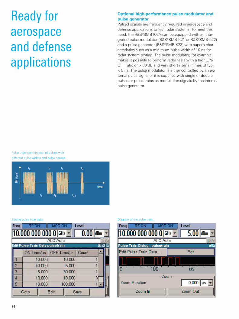
Pulsetrain:combinationofpulseswith
differentpulsewidthsandpulsepauses.
Editing pulse train data. Diagramofthepulsetrain.
Optional high-performance pulse modulator and pulse generatorPulsed signals are frequently required in aerospace and defense applications to test radar systems. To meet this need,theR&S®SMB100Acanbeequippedwithaninte-gratedpulsemodulator(R&S®SMB-K21orR&S®SMB-K22)andapulsegenerator(R&S®SMB-K23)withsuperbchar-acteristicssuchasaminimumpulsewidthof10nsforradar system testing. The pulse modulator, for example, makesitpossibletoperformradartestswithahighON/OFFratioof>80 dBandveryshortrise/falltimesoftyp.<5ns.Thepulsemodulatoriseithercontrolledbyanex-ternalpulsesignaloritissuppliedwithsingleordoublepulses or pulse trains as modulation signals by the internal pulse generator.
SMB100A_bro_en_5213_8396_12.indd 16 13.05.2013 12:48:51

Rohde & Schwarz R&S®SMB100ARFandMicrowaveSignalGenerator17
Versatile pulse trainsAn optional feature of the built-in pulse generator is the possibilitytogeneratepulsetrains(R&S®SMB-K27option),whicharecommonlyusedforradarapplications.Anex-ampleofapulsetrainisshowninthefigureontheleft.Incontrast to a single or double pulse, a pulse train is a com-binationofdifferentpulses,whichcanbeaperiodicalornon-periodicalsetofpulses.Pulsewidthandpulsepausecan be set independently and separately for each pulse. This makes it possible to generate staggered pulses or to applyjittertopulsewidthandpulsepause.Upto2047differentpulseswitharepetitionof1tomax.65535arepossible.Thisyieldsverylongpulsetrainsequencesfortesting.
Wide temperature range and high permissible operating altitudeThe R&S®SMB100A functions reliably under extreme con-ditionsowingtoitswidetemperaturerangeof0°Cto+55°Candamaximumpermissibleoperatingaltitudeof4600mabovesealevel.
Sanitizing of user data for secured areasTo meet requirements for secured areas, an erase and sanitizeprocedurehasbeendevelopedthatreliablyerasesuser data from the instrument. This ensures that no sensi-tivedatawillleavethesecuredarea.Moreover,LANandUSBportscanbedisabledbymeansofasecuritypass-wordandthedisplaycanbedisabledaswell.
High-quality shieldingSensitivitymeasurementsonlow-noisesatellitereceiverscanonlybemadewithRF-leakage-proofsignalsources.ThecomprehensiveshieldingoftheR&S®SMB100AbasedonsophisticatedtechnologiesensureslowRFleakageex-actly for this purpose.
RearviewoftheR&S®SMB100A.
SMB100A_bro_en_5213_8396_12.indd 17 13.05.2013 12:48:53

18
thatneedstobecorrected,theusercanenterthelevelcorrectionvaluesasafunctionofthefrequency.Auto-maticinterpolationofthecorrectionvaluesisperformedbetweenthesefrequencypoints.Tosimplifythis,theR&S®SMB100Acanalsoautomaticallyincludethelevelcorrectionvaluesatthepressofabuttonbyusingadi-rectlyconnectedR&S®NRP-Zxxpowersensor.
ThescreenshotsshowthefrequencyresponsecorrectionforanRFcableintherangefrom8 GHzto10 GHz.With-outfrequencyresponsecorrection,thelevelerror(mea-suredwiththeR&S®NRP-Z81)amountstoapprox.1.5 dBat10 GHzduetocableloss.Afterthecorrectionvaluesintherangefrom8 GHzto10 GHzhavebeenautomaticallymeasuredandstoredwiththeR&S®NRP-Z81,theleveler-rorwillbeautomaticallycompensatedforwhentheUserCorrectionfunctionisactivated.
User-defined correction of external frequency responses
Themeasuredlevelcorrectionvaluesarestoredinatabletogetherwith
the user-selected frequencies.
WithoutfrequencyresponsecorrectionoftheRFcable,thelevelerror
(measuredwiththeR&S®NRP-Z81powersensor)amountstoapprox.
1.5 dBat10 GHz(nominalvalue:5 dBm).
TheconnectedR&S®NRP-Z81powersensorautomaticallymeasures
and stores the frequency response of the RF cable.
AftertheUserCorrectiontablehasbeenactivated,theR&S®SMB100A
adaptsitsoutputpowerinordertocompensateforthefrequency
response of the RF cable.
Testsetupsincludingcables,poweramplifiersorfiltersalwayshavefrequencyresponses.Thesignalgenera-tor can compensate for the frequency response. The R&S®SMB100AfeaturestheUserCorrectionfunctionforpreciselythispurpose.Foraknownfrequencyresponse
SMB100A_bro_en_5213_8396_12.indd 18 13.05.2013 12:48:53

Closed loop power control ensures highly accurate and stable input power to the DUT irrespective of unwanted power drifts or changes in the setup
¸SMB100A
DUT
Cable loss
Mismatch
Loss/gain
Module/s
¸NRP-ZxxPower Measurement
Rohde & Schwarz R&S®SMB100ARFandMicrowaveSignalGenerator19
Closed loop power control
The best solution to this problem is “closed loop powercontrol”inrealtime–astandardfeatureoftheR&S®SMB100A.Inthesetupbelow,itensureshighlyaccu-rateandverystableinputpowertotheDUT,irrespectiveofunwantedpowerdriftsorchangesinthesetup.
FormeasuringtheDUTinputpower,adirectionalcouplerplustheR&S®NRP-Zxxpowersensorconnectedtothedi-rectionalcouplercanbeused.AnattractivealternativetothedirectionalcouplerplustheR&S®NRP-Zxxpowersen-soristheR&S®NRP-Z28levelcontrolsensor.Themeasure-mentresultfromtheR&S®NRP-ZxxortheR&S®NRP-Z28isfedbacktotheR&S®SMB100A,whichimmediatelyad-justsitsoutputpowertocompensateforthediscrepancybetweenwantedandmeasuredlevel.
ClosedlooppowercontrolwithR&S®NRP-Z28levelcontrolsensor.
ClosedlooppowercontrolwithdirectionalcouplerplusR&S®NRP-Zxx
powersensor.
One important performance requirement in many applica-tionsisthegenerationofhighlyaccurateandstablepowerfortestingDUTs(e.g.poweramplifiers).ThisisnotatrivialtasksincetherealpowerdirectlyappliedtotheDUTisaf-fectedbythelevelaccuracyofthesignalgenerator,thelosses due to cables, the losses due to modules or compo-nents and, last but not least, by mismatching. In addition, the frequency response of an amplifier in the setup might showanunwantedtemperaturedependency.
SMB100A_bro_en_5213_8396_12.indd 19 13.05.2013 12:48:59

20
Flexible service concept
A minimum of modules in the R&S®SMB100A
meanshighreliabilityandeasyservicing
(thephotoshowsthe6 GHzmodel).
Built-in selftest of modules to support troubleshootingA built-in selftest carries out an operational check of the instrumentandservesasatroubleshootingaidduringser-vicing.Thesimpleandstraightforwardarchitecturewithveryfewmodulescutsthetimerequiredfortroubleshoot-ingandrepairtoaminimum.Moreover,forallinstrumentsupto6 GHz,theR&S®SMB100Adoesnotneedtoberecalibrated if a module has to be replaced because all re-placementmodulescomefullyadjusted.Asimplefunctioncheck is usually sufficient to ensure the outstanding speci-ficationsoftheR&S®SMB100A.Do-it-yourselfservicingcanbecompletedinjust45minutesonaverage.
Complete calibration only every three yearsA complete calibration is recommended for the R&S®SMB100Aonlyeverythreeyearsandcan,ofcourse,also be performed on-site.
Servicing on-site or at a Rohde & Schwarz service centerThe R&S®SMB100A is designed for maximum reliability andeasyservicingtomaximizeuptimeinallapplica-tionfieldsandsignificantlyreducecostofownership.CustomerscanchoosebetweencallingonacertifiedRohde&Schwarzservicecenterasusualorservicing theinstrumentthemselves.
SMB100A_bro_en_5213_8396_12.indd 20 13.05.2013 12:48:59

Rohde & Schwarz R&S®SMB100ARFandMicrowaveSignalGenerator21
Specifications in briefSpecifications in briefFrequency
Frequency range R&S®SMB-B101 9 kHzto1.1 GHz
R&S®SMB-B102 9 kHzto2.2 GHz
R&S®SMB-B103 9 kHzto3.2 GHz
R&S®SMB-B106 9 kHzto6 GHz
R&S®SMB-B112/-B112L 100 kHzto12.75 GHz
R&S®SMB-B120/-B120L 100 kHzto20 GHz
R&S®SMB-B140/-B140L 100 kHzto40 GHz
Setting time SCPI mode <3ms
Listmode <1ms
Level
Maximumspecifiedoutputpower(PEP) R&S®SMB-B101/-B102/-B103/-B106/-B112/-B112L1 MHz<f≤12.75 GHz
+18 dBm
R&S®SMB-B120withR&S®SMB-B31,50MHz<f≤20 GHz +16 dBm
R&S®SMB-B120LwithR&S®SMB-B31, 100MHz<f≤20 GHz
+19 dBm
R&S®SMB-B140withR&S®SMB-B32,50 MHz<f≤40 GHz +13 dBm
R&S®SMB-B140LwithR&S®SMB-B32,50 MHz<f≤40 GHz +16 dBm
Minimumspecifiedoutputpower R&S®SMB-B101/-B102/-B103/-B106/-B112/-B120/-B140 –120 dBm
R&S®SMB-B112L –5 dBm
R&S®SMB-B120L/-B140L 0 dBm
Settingtime(withoutswitchingofthemechanicalattenuator)
SCPI mode <2.5ms
Listmode <1ms
Spectral purity
SSB phase noise f=1 GHz,carrieroffset=20 kHz, 1 Hzmeasurementbandwidth
<–122 dBc,typ.–128 dBc
f=10 GHz,carrieroffset=20 kHz, 1 Hzmeasurementbandwidth
<–102 dBc,typ.–108 dBc
Harmonics
R&S®SMB-B101/-B102/-B103/-B106/-B112/-B112L 1MHz<f≤6GHz;level≤13dBm1), f>6GHz;level≤10dBm1)
<–30dBc
R&S®SMB-B120/-B120L/-B140/-B140L standard;level≤8dBm1)
f>1MHz <–30dBc
withR&S®SMB-B25/-B26lowharmonicoption,lowharmonicfilteron,level≤10dBm1)
1MHz<f≤150MHz <–30dBc
150MHz<f≤3GHz <–58dBc
3GHz<f≤20GHz <–50dBc
f>20GHz <–60dBc(meas.)
Supported modulation modes
AM standard
AM depth 0 % to 100 %
FM/φM standard
MaximumFMdeviation f=10 GHz 32 MHz
MaximumφMdeviation f=10 GHz 320rad
Pulse R&S®SMB-K21/-K22pulsemodulator
Rise/falltime <20ns,typ.<5ns
ON/OFFratio >80 dB
Minimumpulsewidthofpulsegeneratoroutput 10 ns
Connectivity
Remote control GPIBIEEE-488.2,Ethernet(TCP/IP), USB
Peripherals USB
1) Ormaximumspecifiedoutputpower,whicheverislower.
SMB100A_bro_en_5213_8396_12.indd 21 13.05.2013 12:48:59

22
Ordering informationDesignation Type Order No.Base unit
RFandMicrowaveSignalGenerator1) R&S®SMB100A 1406.6000.02
Includingpowercable,QuickStartGuideandCD-ROM(withoperatingandservicemanual)
Options
RFPath/FrequencyOption
9kHzto1.1GHz R&S®SMB-B101 1407.2509.02
9kHzto2.2GHz R&S®SMB-B102 1407.2609.02
9kHzto3.2GHz R&S®SMB-B103 1407.2709.02
9kHzto6GHz R&S®SMB-B106 1407.2909.02
100kHzto12.75GHz,withelectronicstepattenuator R&S®SMB-B112 1407.2109.02
100kHzto12.75GHz,withoutstepattenuator R&S®SMB-B112L 1407.2150.02
100kHzto20GHz,withmechanicalstepattenuator R&S®SMB-B120 1407.2209.02
100kHzto20GHz,withoutstepattenuator R&S®SMB-B120L 1407.2250.02
100kHzto40GHz,withmechanicalstepattenuator R&S®SMB-B140 1407.2309.02
100kHzto40GHz,withoutstepattenuator R&S®SMB-B140L 1407.2350.02
OCXO Reference Oscillator 2) R&S®SMB-B1 1407.3005.02
OCXO Reference Oscillator, high performance 2) R&S®SMB-B1H 1407.3070.02
Stereo/RDSCoder3) R&S®SMB-B5 1407.3205.02
HarmonicFilterOption
150MHzto20GHz (onlyavailablewithR&S®SMB-B120/-B120L)
R&S®SMB-B25 1407.1660.02
150MHzto40GHz (onlyavailablewithR&S®SMB-B140/-B140L)
R&S®SMB-B26 1407.1760.02
ReversePowerProtection
(onlyavailablewithR&S®SMB-B112/-B112L) R&S®SMB-B30 1407.1160.02
HighPowerOption
50MHzto20GHz (onlyavailablewithR&S®SMB-B120/-B120L)
R&S®SMB-B31 1407.1260.02
50MHzto40GHz (onlyavailablewithR&S®SMB-B140/-B140L)
R&S®SMB-B32 1407.1360.02
Pulse Modulator for R&S®SMB-B112/-B112L/-B120/-B120L/-B140/-B140L
R&S®SMB-K21 1407.3811.02
PulseModulatorforR&S®SMB-B101/-B102/-B103/-B106 R&S®SMB-K22 1407.3770.02
PulseGenerator R&S®SMB-K23 1407.3786.02
Pulse Train 4) R&S®SMB-K27 1407.3828.02
1) ThebaseunitmustbeorderedtogetherwithanR&S®SMB-B101/-B102/-B103/-B106/-B112/-B112L/-B120/-B120L/-B140/-B140Lfrequencyoption.2) OnlyoneoftheR&S®SMB-B1orR&S®SMB-B1Hoptionscanbeinstalled.3) OnlyavailablewithanR&S®SMB-B101/-B102/-B103/-B106frequencyoption.4) RequirestheR&S®SMB-K23option;onlyavailableforinstrumentswithserialnumber>102400.
SMB100A_bro_en_5213_8396_12.indd 22 13.05.2013 12:49:00

Rohde & Schwarz R&S®SMB100ARFandMicrowaveSignalGenerator23
Designation Type Order No.Recommended extras
19" Rack Adapter R&S®ZZA-S234 1109.4493.00
PowerSensor,9kHzto6GHz,forlevelsupto33dBm; incl.USBadaptercable
R&S®NRP-Z92 1171.7005.42
PowerSensor,DCto40GHz,forlevelsupto20dBm R&S®NRP-Z55 1138.2008.03
PowerSensor,10MHzto18GHz,forlevelsupto33dBm R&S®NRP-Z22 1137.7506.02
KeyboardwithUSBInterface(UScharacterset) R&S®PSL-Z2 1157.6870.04
MousewithUSBInterface,optical R&S®PSL-Z10 1157.7060.03
USBAdapterforR&S®NRP-Zxxpowersensors R&S®NRP-Z4 1146.8001.02
USBSerialAdapterforRS-232remotecontrol R&S®TS-USB1 6124.2531.00
AdaptersforinstrumentswithanR&S®SMB-B112/-B112L/-B120/-B120Lfrequencyoption
Testportadapter,PC3.5mmfemale 1021.0512.00
Testportadapter,PC3.5mmmale 1021.0529.00
Test port adapter, N female 1021.0535.00
Test port adapter, N male 1021.0541.00
AdaptersforinstrumentswithanR&S®SMB-B140/-B140Lfrequencyoption
Testportadapter,2.4mmfemale 1088.1627.02
Test port adapter, 2.92 mm female 1036.4790.00
Test port adapter, 2.92 male 1036.4802.00
Test port adapter, N female 1036.4777.00
Test port adapter, N male 1036.4783.00
Frequency multipliers
FrequencyMultiplier,50GHzto75GHz R&S®SMZ75 1417.4004.02
FrequencyMultiplier,60GHzto90GHz R&S®SMZ90 1417.4504.02
FrequencyMultiplier,75GHzto110GHz R&S®SMZ110 1417.5000.02
Includingwaveguide-towaveguideadapter,DCpoweradapter,USBcable,hexballdriver3/32,operatingmanual,CD-ROMwithoperatingmanual
Options
MechanicallyControlledAttenuatorfortheR&S®SMZ75 R&S®SMZ-B75M1) 1417.6007.02
ElectronicallyControlledAttenuatorfortheR&S®SMZ75 R&S®SMZ-B75E1) 1417.6107.02
MechanicallyControlledAttenuatorfortheR&S®SMZ90 R&S®SMZ-B90M1) 1417.6507.02
ElectronicallyControlledAttenuatorfortheR&S®SMZ90 R&S®SMZ-B90E1) 1417.6607.02
MechanicallyControlledAttenuatorfortheR&S®SMZ110 R&S®SMZ-B110M1) 1417.7003.02
ElectronicallyControlledAttenuatorfortheR&S®SMZ110 R&S®SMZ-B110E1) 1417.7103.02
Documentation
DocumentationofCalibrationValues R&S®DCV-2 0240.2193.18
DKD(ISO17025)CalibrationincludingISO9000calibration R&S®SMB-DKD 1161.3607.02
1) Optionfactoryfitted(onlymechanicallyorelectronicallycontrolledattenuatorscanbefitted).
Service optionsExtended Warranty, one year R&S®WE1SMB100A Please contact your local
Rohde&Schwarzsalesoffice.ExtendedWarranty,twoyears R&S®WE2SMB100A
Extended Warranty, three years R&S®WE3SMB100A
Extended Warranty, four years R&S®WE4SMB100A
ExtendedWarrantywithCalibrationCoverage,oneyear R&S®CW1SMB100A
ExtendedWarrantywithCalibrationCoverage,twoyears R&S®CW2SMB100A
ExtendedWarrantywithCalibrationCoverage,threeyears R&S®CW3SMB100A
ExtendedWarrantywithCalibrationCoverage,fouryears R&S®CW4SMB100A
For data sheet, see PD 5213.8396.22 and www.rohde-schwarz.com
YourlocalRohde&Schwarzexpertwillhelpyoudeterminetheoptimumsolutionforyourrequirements.TofindyournearestRohde&Schwarzrepresentative,visitwww.sales.rohde-schwarz.com
SMB100A_bro_en_5213_8396_12.indd 23 13.05.2013 12:49:00

About Rohde & SchwarzRohde & Schwarz is an independent group of companies specializing in electronics. It is a leading supplier of solu-tions in the fields of test and measurement, broadcasting, radiomonitoring and radiolocation, as well as secure communications. Established more than 75 years ago, Rohde & Schwarz has a global presence and a dedicated service network in over 70 countries. Company headquar-ters are in Munich, Germany.
Certified Quality System
ISO 9001
R&S®isaregisteredtrademarkofRohde&SchwarzGmbH&Co.KG
Tradenamesaretrademarksoftheowners|PrintedinGermany(as)
PD5213.8396.12|Version05.00|May2013|R&S®SMB100A
Datawithouttolerancelimitsisnotbinding|Subjecttochange
©2008-2013Rohde&SchwarzGmbH&Co.KG|81671München,Germany
Regional contact ❙ Europe, Africa, Middle East | +49 89 4129 12345 [email protected]
❙ North America | 1 888 TEST RSA (1 888 837 87 72) [email protected]
❙ Latin America | +1 410 910 79 88 [email protected]
❙ Asia/Pacific | +65 65 13 04 88 [email protected]
❙ China | +86 800 810 8228/+86 400 650 5896 [email protected]
Rohde & Schwarz GmbH & Co. KGwww.rohde-schwarz.com
Environmental commitment ❙ Energy-efficient products ❙ Continuous improvement in environmental sustainability ❙ ISO 14001-certified environmental management system
Service you can rely on❙ Worldwide ❙ Local and personalized❙ Customized and flexible❙ Uncompromising quality ❙ Long-term dependability
5213839612
SMB100A_bro_en_5213_8396_12.indd 24 13.05.2013 12:49:00