Embed Size (px)
Citation preview

R&S®FPS MSRAMulti-Standard Radio AnalyzerUser Manual
User
Man
ual
1176.8574.02 ─ 08(;ÚãØ2)
Test
& Me
asur
emen
t

This manual applies to the following R&S®FPS models with firmware version 1.50 and higher:
● R&S®FPS4 (1319.2008K04)
● R&S®FPS7 (1319.2008K07)
● R&S®FPS13 (1319.2008K13)
● R&S®FPS30 (1319.2008K30)
● R&S®FPS40 (1319.2008K40)
© 2017 Rohde & Schwarz GmbH & Co. KGMühldorfstr. 15, 81671 München, GermanyPhone: +49 89 41 29 - 0Fax: +49 89 41 29 12 164Email: [email protected]: www.rohde-schwarz.comSubject to change – Data without tolerance limits is not binding.R&S® is a registered trademark of Rohde & Schwarz GmbH & Co. KG.Trade names are trademarks of their owners.
The following abbreviations are used throughout this manual: R&S®FPS is abbreviated as R&S FPS. R&S®FPS Multi-StandardRadio Analyzer is abbreviated as R&S FPS MSRA.

ContentsR&S®FPS MSRA
3User Manual 1176.8574.02 ─ 08
Contents1 Preface.................................................................................................... 5
1.1 About this Manual......................................................................................................... 5
1.2 Typographical Conventions.........................................................................................6
2 Welcome to the MSRA Operating Mode...............................................72.1 Starting the MSRA operating mode.............................................................................7
2.2 Understanding the Display Information......................................................................8
3 Typical Applications............................................................................ 14
4 Measurements and Result Displays...................................................15
5 Applications and Operating Modes....................................................175.1 Available Slave Applications..................................................................................... 18
5.2 Selecting the Operating Mode and Slave Applications........................................... 20
5.3 Using the Sequencer in MSRA Mode........................................................................ 22
6 MSRA Basics........................................................................................246.1 Configuration...............................................................................................................24
6.2 Data Acquisition..........................................................................................................25
6.3 Multi-Standard Analysis............................................................................................. 26
6.4 Restrictions for Slave Applications...........................................................................28
6.5 Measurements in the Time and Frequency Domain................................................ 28
7 Configuration........................................................................................307.1 Configuration Overview..............................................................................................31
7.2 Input Source Settings................................................................................................. 33
7.3 Amplitude.....................................................................................................................35
7.4 Frequency Settings.....................................................................................................39
7.5 Trigger Settings...........................................................................................................40
7.6 Data Acquisition and Bandwidth Settings................................................................46
7.7 Output Settings........................................................................................................... 53
7.8 Display Configuration.................................................................................................54
7.9 Automatic Settings..................................................................................................... 54
8 Analysis................................................................................................ 57

ContentsR&S®FPS MSRA
4User Manual 1176.8574.02 ─ 08
8.1 Configuring the Analysis Line................................................................................... 57
9 How to Perform Measurements in MSRA Mode................................59
10 Measurement Example: Analyzing MSR Signals.............................. 62
11 Remote Commands to Perform Measurements in MSRA Mode......6911.1 Introduction................................................................................................................. 69
11.2 Common Suffixes........................................................................................................74
11.3 Activating MSRA Measurements............................................................................... 75
11.4 Configuring MSRA Measurements............................................................................ 80
11.5 Capturing Data and Performing Sweeps................................................................ 104
11.6 Retrieving Results.....................................................................................................110
11.7 Querying the Status Registers.................................................................................114
11.8 Analyzing MSRA Measurements............................................................................. 117
11.9 Commands Specific to MSRA Slave Applications.................................................118
11.10 Programming Example: Analyzing MSR Signals................................................... 120
Annex.................................................................................................. 123
A Annex.................................................................................................. 123A.1 Reference: Format Description for I/Q Data Files.................................................. 123
A.2 Formats for Returned Values: ASCII Format and Binary Format......................... 124
A.3 Sample Rate and Maximum Usable I/Q Bandwidth for RF Input.......................... 125
List of Remote Commands (MSRA)..................................................128
Index....................................................................................................130

PrefaceR&S®FPS MSRA
5User Manual 1176.8574.02 ─ 08
1 Preface
1.1 About this Manual
This R&S FPS MSRA User Manual provides all the information specific to the operat-ing mode. All general instrument functions and settings common to all applicationsand operating modes are described in the main R&S FPS User Manual.
The main focus in this manual is on the measurement results and the tasks required toobtain them. The following topics are included:
● Welcome to the MSRA Operating ModeIntroduction to and getting familiar with the operating mode
● Typical ApplicationsExample measurement scenarios in which the operating mode is frequently used
● Measurements and Result DisplaysDetails on supported measurements and their result types
● MSRA BasicsBackground information on basic terms and principles in the context of the MSRAoperating mode
● MSRA ConfigurationA concise description of all functions and settings available to configure an MSRAmeasurements with their corresponding remote control command
● How to Perform Measurements in MSRA ModeThe basic procedure to perform an MSRA measurement with step-by-step instruc-tions
● Measurement ExamplesDetailed measurement examples to guide you through typical measurement sce-narios and allow you to try out the operating mode immediately
● Optimizing and Troubleshooting the MeasurementHints and tips on how to handle errors and optimize the test setup
● Remote Commands for MSRA MeasurementsRemote commands required to configure and perform MSRA measurements in aremote environment, sorted by tasks(Commands required to set up the environment or to perform common tasks on theinstrument are provided in the main R&S FPS User Manual)Programming examples demonstrate the use of many commands and can usuallybe executed directly for test purposes
● AnnexReference material
● List of remote commandsAlpahabetical list of all remote commands described in the manual
● Index
About this Manual

PrefaceR&S®FPS MSRA
6User Manual 1176.8574.02 ─ 08
1.2 Typographical Conventions
The following text markers are used throughout this documentation:
Convention Description
"Graphical user interface ele-ments"
All names of graphical user interface elements on the screen, such asdialog boxes, menus, options, buttons, and softkeys are enclosed byquotation marks.
KEYS Key names are written in capital letters.
File names, commands,program code
File names, commands, coding samples and screen output are distin-guished by their font.
Input Input to be entered by the user is displayed in italics.
Links Links that you can click are displayed in blue font.
"References" References to other parts of the documentation are enclosed by quota-tion marks.
Typographical Conventions

Welcome to the MSRA Operating ModeR&S®FPS MSRA
7User Manual 1176.8574.02 ─ 08
2 Welcome to the MSRA Operating ModeThe MSRA operating mode is part of the standard R&S FPS firmware and adds func-tionality to perform multi-standard radio analysis.
The R&S FPS MSRA operating mode features:
● Analysis of the same I/Q data in more than one application● Analysis of correlated effects due to multiple standards● Configuration of data acquisition settings only required once for all applications● Overview of all results in one screen in addition to large display of individual results● Common analysis line (time marker) across all applications● Performing measurements in the frequency and time domain (such as channel
power measurements) on I/Q data
This user manual contains a description of the functionality specific to the MSRA oper-ating mode, including remote control operation.
All functions not discussed in this manual are the same as in Signal and SpectrumAnalyzer mode and are described in the R&S FPS User Manual. The latest version isavailable for download at the product homepage
http://www2.rohde-schwarz.com/product/FPS.html.
Additional information
An application note discussing efficient measurements using the MSRA operatingmode is available from the Rohde & Schwarz website:
1EF83: Using the R&S®FSW for Efficient Measurements on Multi- Standard RadioBase Stations (MSRA)
2.1 Starting the MSRA operating mode
MSRA is a new operating mode on the R&S FPS.
Manual operation via an external monitor and mouseAlthough the R&S FPS does not have a built-in display, it is possible to operate it inter-actively in manual mode using a graphical user interface with an external monitor anda mouse connected.It is recommended that you use the manual mode initially to get familiar with the instru-ment and its functions before using it in pure remote mode. Thus, this documentdescribes in detail how to operate the instrument manually using an external monitorand mouse. The remote commands are described in the second part of the document.
To activate the MSRA operating mode
1. Select the MODE key.
Starting the MSRA operating mode

Welcome to the MSRA Operating ModeR&S®FPS MSRA
8User Manual 1176.8574.02 ─ 08
A dialog box opens that contains all operating modes and applications currentlyavailable on your R&S FPS.
2. Select the "Multi Standard Radio Analyzer" tab.
3. Confirm the message informing you that you are changing operating modes.
The R&S FPS closes all active measurement channels in the current operatingmode, then opens a new measurement channel for the MSRA operating mode.
In addition to the "MSRA View", an "MSRA Master" tab is displayed.The Sequencer is automatically activated in continuous mode (see Chapter 5.3,"Using the Sequencer in MSRA Mode", on page 22), starting an I/Q Analyzerdata acquisition with the default settings (but with a "Spectrum" result display). Itcan be configured in the MSRA "Overview" dialog box, which is displayed whenyou select the "Overview" softkey from any menu (see Chapter 7, "Configuration",on page 30).
Remote command:
INST:MODE MSR, see INSTrument:MODE on page 78
2.2 Understanding the Display Information
The following figure shows a screen display during MSRA operation. All different infor-mation areas are labeled. They are explained in more detail in the following sections.
● The orange background of the screen behind the measurement channel tabs indi-cates that you are in MSRA operating mode.
● The icon on the tab label indicates that the displayed trace (e.g. in an MSRAslave application) no longer matches the currently captured data. This may be thecase, for example, if a data acquisition was performed in another slave application.As soon as the result display is refreshed, the icon disappears.
● The icon indicates that an error or warning is available for that measurementchannel. This is particularly useful if the MSRA View tab is displayed.
An orange "IQ" indicates that the results displayed in the MSRA slave application(s) nolonger match the data captured by the MSRA Master. The "IQ" disappears after theresults in the slave application(s) are refreshed.
Understanding the Display Information

Welcome to the MSRA Operating ModeR&S®FPS MSRA
9User Manual 1176.8574.02 ─ 08
1 = MSRA View (overview of all active channels in MSRA mode)2 = MSRA Master (data acquisition channel with global configuration settings)3 = Measurement channel tab for individual MSRA slave application4 = Channel bar for firmware and measurement settings of current slave application5+6 = Window title bar with diagram-specific (trace) information and analysis interval (slave applications)7 = Diagram area8 = Diagram footer with diagram-specific information, depending on evaluation9 = Instrument status bar with error messages, progress bar and date/time display
The diagram area varies depending on the type of measurement channel, as describedin detail in the following topics.
Window title bar information
For each diagram, the header provides the following information:
Figure 2-1: Window title bar information in MSRA mode
1 = Window number2 = Window type3 = Trace color4 = Trace number5 = Detector6 = Trace mode7 = Analysis interval8 = Analysis line indication
Diagram footer information
The information in the diagram footer (beneath the diagram) depends on the evalua-tion:
Understanding the Display Information

Welcome to the MSRA Operating ModeR&S®FPS MSRA
10User Manual 1176.8574.02 ─ 08
● Center frequency● Number of sweep points● Range per division (x-axis)● Span (Spectrum)
Status bar information
Global instrument settings, the instrument status and any irregularities are indicated inthe status bar beneath the diagram. Furthermore, the progress of the current operationis displayed in the status bar.
If an error or warning is available for a measurement channel, the icon is displayednext to the tab label in the channel bar.
2.2.1 MSRA View
The MSRA View is an overview of all active channels in MSRA mode, similar to theMultiView tab in Signal and Spectrum Analyzer mode. At the top of the screen theMSRA Master is displayed, i.e. the application that captures data. Beneath the MSRAMaster, all active slave applications are displayed in individual windows. Each slaveapplication has its own channel bar with the current settings as well as a button inorder to switch to that slave application tab directly.
The MSRA View displays the following basic elements:
1 = Channel information bar for the MSRA Master2 = Slave application data coverage for each active slave application3 = Result display for MSRA Master (for entire capture buffer)4 = Channel information bar for slave application with button to switch to slave application tab5 = Result display for slave application (for analysis interval)
Understanding the Display Information

Welcome to the MSRA Operating ModeR&S®FPS MSRA
11User Manual 1176.8574.02 ─ 08
2.2.2 MSRA Master
The MSRA Master is the only channel that captures data. It also controls global config-uration settings for all slave applications. The MSRA Master channel itself is implemen-ted as an I/Q Analyzer slave application. The MSRA Master measurement channelcannot be deleted or replaced.
The following figure shows the screen elements specific to the MSRA Master.
1 = Channel information bar for the MSRA Master2 = Data coverage for each active slave application3 = Analysis line4 = Result display for MSRA Master (for entire capture buffer)
Channel bar information
The channel bar shows the firmware and measurement information for data acquisitionand global configuration.
Table 2-1: Information displayed in the channel bar for the MSRA Master
Ref Level Reference level
(m.+el.)Att (Mechanical and electronic) RF attenuation
Ref Offset Reference level offset
Freq Center frequency
AQT Defined measurement time, i.e. the duration of data acquisition to the cap-ture buffer
Rec Length Defined record length (number of samples to capture)
SRate Defined sample rate for data acquisition
RBW (Spectrum evaluation only) Resolution bandwidth calculated from thesample rate and record length
Understanding the Display Information

Welcome to the MSRA Operating ModeR&S®FPS MSRA
12User Manual 1176.8574.02 ─ 08
In addition, the channel bar also displays information on instrument settings that affectthe measurement results even though this is not immediately apparent from the displayof the measured values (e.g. transducer or trigger settings). This information is dis-played only when applicable for the current measurement. For details see theR&S FPS Getting Started manual.
Data coverage for each active slave application
Each slave application obtains an extract of the data captured by the MSRA Master(see also Chapter 6.3, "Multi-Standard Analysis", on page 26). Generally, if a signalcontains data channels for multiple standards, the individual slave applications areused to analyze the channel for the corresponding standard. Thus, it is of interest toknow which slave application is analyzing which part of the captured data, or more pre-cisely, which data channel. The MSRA Master display indicates the data covered byeach slave application, restricted to the channel bandwidth used by the correspondingstandard, by vertical blue lines labeled with the slave application name. For slave appli-cations that support several standards (e.g. VSA, LTE) an estimated or user-definedbandwidth is indicated.
2.2.3 MSRA Slave Applications
The data captured by the MSRA Master measurement (or only parts of it) can be eval-uated by various slave applications. The measurement channel for each slave applica-tion contains the settings and results for the slave application data extract from thecapture buffer.
The following figure shows the screen elements specific to the MSRA slave applicationtabs.
Understanding the Display Information

Welcome to the MSRA Operating ModeR&S®FPS MSRA
13User Manual 1176.8574.02 ─ 08
1 = Channel information bar for slave application2 = Analysis interval for current evaluation3 = Result display for analysis interval4 = Analysis line
The display for the individual MSRA slave applications is identical to the display in Sig-nal and Spectrum Analyzer mode except for the following differences:
● The analysis interval indicates which part of the capture buffer is being evaluatedand displayed in each window.
● The acquisition time indicated in the channel bar (Meas Time) indicates the ana-lyzed measurement time, not the captured time.
● Any bandwidth or sample rate values refer to the slave application data, not to theactual data acquisition from the input signal.
● The analysis line for time-based displays is only available in MSRA mode. It repre-sents a common time marker in all slave applications whose analysis intervalincludes that time (see "Analysis line" on page 27).
For details on the individual slave application displays see the corresponding UserManuals for those applications.
Understanding the Display Information

Typical ApplicationsR&S®FPS MSRA
14User Manual 1176.8574.02 ─ 08
3 Typical ApplicationsThe technological advances made in the field of mobile radio have given rise to a widevariety of standards over the past several decades. These standards, which includethose produced by the global cooperative for standardization – the 3rd GenerationPartnership Project (3GPP) – are based on various transmission technologies. Net-work operators can deploy GSM/EDGE, WCDMA, TD-SCDMA and LTE or combina-tions of these four standards.
To handle these complex scenarios, the Multistandard Radio Base Station (MSR-BS)was developed. These can transmit and receive multiple standards simultaneously onvarious carriers. An MSR-BS combines at least two different radio access technologies(RAT).
Specifications and Tests
3GPP has published the specifications TS 37.141 and TS 37.104 for multistandardbase stations. The latter describes the minimum requirements for multistandard basestations in terms of RF requirements for the downlink and uplink. TS 37.141 definesthe tests and test requirements for the MSR-BS based on these RF requirements.
To allow for efficient MSR-BS testing, TS 37.141 includes test configurations. The goalof these test configurations is to significantly reduce the complexity of the many possi-ble test scenarios. They are limited to the worst-case scenarios with the strictest crite-ria. Thus, for example, a test configuration is provided for receiver tests in which twosignals – a GSM carrier and an LTE carrier with a BWChannel = 5 MHz – are positionedat the lower and upper edge of BWRF while maintaining Foffset-RAT. This allows receivertests to be performed with a configuration that fully utilizes the maximum bandwidthBWRF of the MSR-BS.
MSR-BS Testing using R&S FPS Multi-Standard Radio Analysis
The newly introduced R&S FPS MSRA mode allows you to capture signals from a mul-tistandard base station and analyze the same data in various standard applications.

Measurements and Result DisplaysR&S®FPS MSRA
15User Manual 1176.8574.02 ─ 08
4 Measurements and Result DisplaysMSRA measurement
The only true measurement in MSRA mode in which I/Q data from the input signal iscaptured and stored is performed by the MSRA Master. This data acquisition is per-formed as in the I/Q Analyzer application, i.e. a specified frequency span of the inputsignal is swept for a specified measurement time. The captured I/Q data can then beanalyzed in various different applications.
Result displays
The data that was captured by the MSRA Master can be evaluated in various differentapplications. All evaluation modes available for the MSRA applications are displayed inthe selection bar in SmartGrid mode.
For details on working with the SmartGrid see the R&S FPS Getting Started manual.
The result displays available in MSRA mode are those described for the individualapplications. The MSRA Master is implemented as an I/Q Analyzer application and hasthe same result displays.
See the R&S FPS I/Q Analyzer User Manual for a description of the result displaysavailable for the I/Q Analyzer and thus the MSRA Master.
Measurements in the time and frequency domain
The I/Q Analyzer application (not Master) in MSRA mode can also perform measure-ments on the captured I/Q data in the time and frequency domain (see also Chap-ter 6.5, "Measurements in the Time and Frequency Domain", on page 28).
This allows you to perform standard-specific and general power measurements (suchas ACLR or SEM) or statistical evaluations, as well as analyzing the EVM or modula-tion accuracy, on the same captured I/Q data.

Measurements and Result DisplaysR&S®FPS MSRA
16User Manual 1176.8574.02 ─ 08
Time and frequency-based measurements are configured using the same settings andprovide similar results as in the Spectrum application. In addition, the analysis intervalused for the measurement is indicated as in all MSRA applications.
The time and frequency domain measurements and the available results are describedin detail in the R&S FPS User Manual.

Applications and Operating ModesR&S®FPS MSRA
17User Manual 1176.8574.02 ─ 08
5 Applications and Operating ModesThe R&S FPS provides several applications for different analysis tasks and differenttypes of signals, e.g. W-CDMA, I/Q analysis or basic spectrum analysis. When youactivate an application, a new measurement channel is created which determines themeasurement settings for that application. The same application can be activated withdifferent measurement settings by creating several channels for the same application.Each channel is displayed in a separate tab on the screen.
The maximum number may be limited further by the available memory on the instru-ment.
Independent vs correlating measurements
With the conventional R&S FPS Signal and Spectrum Analyzer you can performseveral different measurements almost simultaneously. However, the individual mea-surements are independent of each other - each application captures and evaluatesits own set of data, regardless of what the other applications do.
In some cases it may be useful to analyze the exact same input data using differentapplications. For example, imagine capturing data from a base station and analyzingthe RF spectrum in the Analog Demodulation application. If a spur or an unexpectedpeak occurs, you may want to analyze the same data in the I/Q Analyzer to see thereal and imaginary components of the signal and thus detect the reason for the irregu-lar signal. Normally when you switch to a different application, evaluation is performedon the data that was captured by that application, and not the previous one. In ourexample that would mean the irregular signal would be lost. Therefore, a second oper-ating mode is available in the R&S FPS: Multi-Standard Radio Analyzer (MSRA) mode.
Multi-Standard Radio Analyzer mode
In Multi-Standard Radio Analyzer (MSRA) mode, data acquisition is performed onceas an I/Q measurement by a master application, and the captured data is then evalu-ated by any number of slave applications for different radio standards. Data acquisitionand global configuration settings are controlled globally, while the evaluation and dis-play settings can be configured individually for each slave application. Using the Multi-Standard Radio Analyzer, unwanted correlations between different signal componentsusing different transmission standards can be detected. Thus, for example, an irregu-larity in a GSM burst can be examined closer in the R&S FPS 3G FDD BTS (W-CDMA)slave application to reveal dependencies like a change in the EVM value.
Distinct operating modes
Although the applications themselves are identical in all operating modes, the handlingof the data between applications is not. Thus, the operating mode determines whichslave applications are available and active. Whenever you change the operating mode,the currently active measurement channels are closed. The default operating mode isSignal and Spectrum Analyzer mode; however, the presetting can be changed.

Applications and Operating ModesR&S®FPS MSRA
18User Manual 1176.8574.02 ─ 08
Remote command:
INST:MODE MSR, see INSTrument:MODE on page 78
Switching between applications
When you switch to a new application, a set of parameters is passed on from the cur-rent application to the new one:● center frequency and frequency offset● reference level and reference level offset● attenuation
After initial setup, the parameters for the measurement channel are stored upon exitingand restored upon re-entering the channel. Thus, you can switch between applicationsquickly and easily.
5.1 Available Slave Applications
Not all options available for the R&S FPS are supported as slave applications in theMSRA mode. The supported slave applications are listed here. Note that some of theapplications are provided with the base unit, while others are available only if the corre-sponding firmware options are installed.
Currently, only applications for base-station tests and those that process I/Q data aresupported in MSRA mode, in particular:● I/Q Analyzer● Analog Demodulation● Pulse measurements● GSM● 3G FDD BTS● TD-SCDMA BTS● cdma2000 BTS● 1xEV-DO BTS● WLAN● Vector Signal Analysis (VSA)● LTE (Downlink)
I/Q Analyzer.................................................................................................................. 19Pulse Measurements.................................................................................................... 19GSM.............................................................................................................................. 193G FDD BTS................................................................................................................. 19TD-SCDMA BTS........................................................................................................... 19cdma2000 BTS............................................................................................................. 201xEV-DO BTS............................................................................................................... 20LTE DL.......................................................................................................................... 20
Available Slave Applications

Applications and Operating ModesR&S®FPS MSRA
19User Manual 1176.8574.02 ─ 08
I/Q AnalyzerThe I/Q Analyzer slave application provides measurement and display functions for I/Qsignals. Evaluation of the captured I/Q data in the frequency and time domain is alsopossible.
For details see the R&S FPS I/Q Analyzer User Manual.
Remote command: INST:SEL IQ, see INSTrument[:SELect] on page 78
Pulse MeasurementsThe Pulse slave application requires an instrument equipped with the Pulse Measure-ments option, R&S FPS-K6. This slave application provides measurement functions forpulsed signals.
For details see the R&S FPS-K6 User Manual.
Remote command: INST:SEL PULSE, see INSTrument[:SELect] on page 78
GSMThe GSM slave application requires an instrument equipped with the correspondingoptional software. This slave application provides measurement functions for measur-ing GSM signals.
For details see the R&S FPS GSM User Manual.
Remote command: INST:SEL GSM, see INSTrument[:SELect] on page 78
3G FDD BTSThe 3G FDD BTS slave application requires an instrument equipped with the 3GPPBase Station Measurements option, R&S FPS-K72. This slave application providestest measurements for WCDMA downlink signals (base station signals) according tothe test specification.
RF measurements are not supported in MSRA mode.
For details see the R&S FPS 3G FDD User Manual.
Remote command: INST:SEL BWCD, see INSTrument[:SELect] on page 78
TD-SCDMA BTSThe TD-SCDMA BTS slave application requires an instrument equipped with the TD-SCDMA BTS Measurements option, R&S FPS-K82. This slave application providestest measurements for TD-SCDMA BTS downlink signals (base station signals)according to the test specification.
RF measurements are not supported in MSRA mode.
For details see the R&S FPS TD-SCDMA User Manual.
Remote command: INST:SEL BTDS, see INSTrument[:SELect] on page 78
Available Slave Applications

Applications and Operating ModesR&S®FPS MSRA
20User Manual 1176.8574.02 ─ 08
cdma2000 BTSThe cdma2000 BTS slave application requires an instrument equipped with thecdma2000 BTS Measurements option, R&S FPS-K82. This slave application providestest measurements for cdma2000 BTS downlink signals (base station signals) accord-ing to the test specification.
RF measurements are not supported in MSRA mode.
For details see the R&S FPS cdma2000 User Manual.
Remote command: INST:SEL BC2K, see INSTrument[:SELect] on page 78
1xEV-DO BTSThe 1xEV-DO BTS slave application requires an instrument equipped with the 1xEV-DO BTS Measurements option, R&S FPS-K84. This slave application provides testmeasurements for 1xEV-DO BTS downlink signals (base station signals) according tothe test specification.
RF measurements are not supported in MSRA mode.
For details see the R&S FPS 1xEV-DO User Manual.
Remote command: INST:SEL BDO, see INSTrument[:SELect] on page 78
LTE DLThe LTE Downlink slave application requires an instrument equipped with the LTEDownlink option, R&S FPS-K100 or R&S FPS-K104. This slave application providestest measurements for LTE downlink signals (base station signals) according to thetest specification.
Frequency sweep measurements are not supported in MSRA mode.
For details see the R&S FPS LTE DL User Manual.
Remote command: INST:SEL LTE, see INSTrument[:SELect] on page 78
5.2 Selecting the Operating Mode and Slave Applications
Access: MODE
The default operating mode is Signal and Spectrum Analyzer mode, however, the pre-setting can be changed.
(See the "Instrument Setup" chapter in the R&S FPS User Manual).
Selecting the Operating Mode and Slave Applications

Applications and Operating ModesR&S®FPS MSRA
21User Manual 1176.8574.02 ─ 08
Switching the operating mode.......................................................................................21Selecting an MSRA slave application........................................................................... 21
└ New Channel.................................................................................................. 21└ Replace Current Channel............................................................................... 21
Closing an application................................................................................................... 22
Switching the operating modeTo switch the operating mode, select the corresponding tab (see Chapter 2.1, "Startingthe MSRA operating mode", on page 7).
Remote command: INSTrument:MODE on page 78
Selecting an MSRA slave applicationTo start a new or replace an existing slave application, select the corresponding buttonin the correct tab.
Remote command: INSTrument[:SELect] on page 78
New Channel ← Selecting an MSRA slave applicationThe slave application selected on this tab is started in a new channel, i.e. a new tab inthe display.
Remote command: INSTrument:CREate[:NEW] on page 75INSTrument[:SELect] on page 78
Replace Current Channel ← Selecting an MSRA slave applicationThe slave application selected on this tab is started in the currently displayed channel,replacing the current slave application.
Remote command: INSTrument:CREate:REPLace on page 76
Selecting the Operating Mode and Slave Applications

Applications and Operating ModesR&S®FPS MSRA
22User Manual 1176.8574.02 ─ 08
Closing an applicationTo close an application, simply close the corresponding tab by selecting the "x" next tothe channel name.
Remote command: INSTrument:DELete on page 76
5.3 Using the Sequencer in MSRA Mode
When you switch to MSRA mode, the Sequencer is automatically activated in continu-ous mode. Unless it is stopped or you select a different Sequencer mode, theR&S FPS will continuously perform a data acquisition (MSRA Master), then evaluatethe data in the active slave applications one after the other, then repeat the data acqui-sition and evaluate the new data etc. The tabs are updated after each measurement orevaluation. This behaviour is identical to Signal and Spectrum Analyzer mode (also forSingle Sequence or Channel-Defined Sequence modes).
However, if you switch the Sequencer off, the behaviour of the sweep functions isslightly different to Signal and Spectrum Analyzer mode (see also "Performing sweeps"on page 25):
● If continuous sweep is active (default) and you switch to a different slave applica-tion, continuous sweep is aborted. This is necessary in order to evaluate the samedata in different slave applications without overwriting the data in the capture buf-fer. Continuous sweep can be started again as usual.
● Only the slave application that is currently displayed when a measurement is per-formed is updated automatically. A new "Refresh" function is available to updatethe display in one or all other slave applications.
For details on the Sequencer function see the R&S FPS User Manual.
The "Sequencer" menu is available from the toolbar.
Sequencer StateActivates or deactivates the Sequencer. If activated, sequential operation according tothe selected Sequencer mode is started immediately.
Remote command: SYSTem:SEQuencer on page 109INITiate<n>:SEQuencer:IMMediate on page 107INITiate<n>:SEQuencer:ABORt on page 107
Sequencer ModeDefines how often which measurements are performed. The currently selected modesoftkey is highlighted blue. During an active Sequencer process, the selected modesoftkey is highlighted orange.
"Single Sequence"Each measurement is performed once, until all measurements in allactive channels have been performed.
Using the Sequencer in MSRA Mode

Applications and Operating ModesR&S®FPS MSRA
23User Manual 1176.8574.02 ─ 08
"Continuous Sequence"The measurements in each active channel are performed one afterthe other, repeatedly, in the same order, until sequential operation isstopped.This is the default Sequencer mode.
"Channel Defined Sequence"First, a single sequence is performed. Then, only channels in continu-ous sweep mode are repeated.
Remote command: INITiate<n>:SEQuencer:MODE on page 108
Refresh AllThis function is only available if the Sequencer is deactivated, no sweep is currentlyrunning, and only in MSRA mode.
The data in the capture buffer is re-evaluated by all active slave applications, for exam-ple after a new sweep was performed while the Sequencer was off.
Note: To update only the displays in the currently active slave application, use the"Refresh" function in the "Sweep" menu for that slave application (see " Refresh(MSRA only)" on page 51).For details on the MSRA operating mode, see the R&S FPS MSRA User Manual.
Remote command: INITiate<n>:SEQuencer:REFResh[:ALL] on page 108
Using the Sequencer in MSRA Mode

MSRA BasicsR&S®FPS MSRA
24User Manual 1176.8574.02 ─ 08
6 MSRA BasicsSome background knowledge on basic terms and principles used in MSRA operatingmode is provided here for a better understanding of the required configuration settings.
6.1 Configuration
Master parameters
In MSRA mode, only the MSRA Master performs a data acquisition. Thus, all parame-ters that determine how the I/Q data is captured from the I/Q channel can only be con-figured in the MSRA Master tab. In all slave application tabs, these settings are deacti-vated (or have a different meaning).
Typical master parameters include:● Sample rate● Record length● Bandwidth● Center frequency● Reference level● Trigger settings● External reference● Impedance, preamplification, attenuation
Channel-specific parameters
Each slave application, however, can define all parameters concerning analysis indi-vidually.
Typical channel-specific parameters include:● Center frequency, duration and number of trace points for the slave application
data extract● Offset of the slave application data extract from the trigger event● Evaluation methods● Range and scaling● Trace mode● Marker positions
Conflicting parameters
Master and channel-specific parameters can be configured independantly of oneanother, in any order that is convenient to you. However, there are dependenciesbetween the parameters, as the slave applications can only evaluate data that hasbeen captured by the MSRA Master previously. Thus, configuring parameters is not
Configuration

MSRA BasicsR&S®FPS MSRA
25User Manual 1176.8574.02 ─ 08
restricted, but you are informed about the violation of possible restrictions by errormessages in the status bar of the slave applications where necessary.
6.2 Data Acquisition
As mentioned before, only the MSRA Master performs a data acquisition. Thus, theMSRA Master defines the center frequency, sample rate and record length of the cap-tured I/Q data. It also defines the trigger event, thus all slave applications have thesame trigger. However, an offset from the trigger can be defined by the individual slaveapplications (see "Trigger offset vs. capture offset" on page 27).
Performing sweeps
When you switch to MSRA mode, the Sequencer is automatically activated in continu-ous mode. The MSRA Master continuously performs a data acquisition. If any slaveapplications are activated, then after each measurement, the data in the active slaveapplications is evaluated one after the other. The MSRA Master will then repeat thedata acquisition and evaluate the new data etc. The channel displays are updated aftereach measurement or evaluation.
Alternatively, you can perform measurements manually. You can start a single or con-tinuous sweep from any slave application, which updates the data in the capture bufferand the results in the current slave application. The results in the other slave applica-tions, however, remain unchanged. You must refresh them manually, either individuallyor all at once, using a "Refresh" function.
Note that in continuous sweep mode, sweeping is aborted when you switch to a dif-ferent slave application. You can then continue sweeping from there. This is necessaryin order to evaluate the same data in different slave applications without overwriting thedata in the capture buffer.
In single sweep mode, only one sweep is performed; a sweep count is not available -neither for the MSRA Master, nor for the slave applications. However, depending onthe slave application, a statistics count may be available for statistics based on a singledata acquisition. Trace averaging is performed as usual for sweep count = 0, the cur-rent trace is averaged with the previously stored averaged trace.
Data availability
The slave applications can only receive data that is available in the capture buffer. Assoon as data has been stored to the capture buffer successfully, a status bit (#9) in theSTAT:OPER register is set. If the required slave application data is not available, anerror message is displayed. Details on restrictions are described in Chapter 6.4,"Restrictions for Slave Applications", on page 28.
Data Acquisition

MSRA BasicsR&S®FPS MSRA
26User Manual 1176.8574.02 ─ 08
6.3 Multi-Standard Analysis
Slave application data
The slave applications receive data for analysis from the capture buffer, if necessaryresampled or with filters applied. The slave applications can define their own centerfrequency, sample rate and record length for their slave application data, which is anextract of the capture buffer data. The slave applications may not request moresample points than the captured data contains, or samples from a frequency outsidethe range of the capture buffer, for example.
Generally, if a signal contains data channels for multiple standards, the individual slaveapplications are used to analyze the channel for the corresponding standard. Thus, it isof interest to know which slave application, or more precisely: which data channel isanalyzing which part of the captured data and how each data channel is correlated (intime) to others.
The MSRA Master display indicates the data covered by each slave application,restricted to the channel bandwidth used by the corresponding standard, by verticalblue lines labeled with the slave application name. For slave applications that supportseveral standards (e.g. VSA, LTE) an estimated or user-defined bandwidth is indica-ted.
Figure 6-1: MSRA Master indicating covered bandwidth for 4 slave applications
Analysis interval
Each slave application receives an extract of the data from the capture buffer. How-ever, the individual evaluation methods of the slave application need not analyze thecomplete data range. Some slave applications allow you to select a specific part of thedata for analysis, e.g. an individual frame, burst or pulse, or to use an offline trigger
Multi-Standard Analysis

MSRA BasicsR&S®FPS MSRA
27User Manual 1176.8574.02 ─ 08
that defines an additional offset to the capture offset. The data range that is actuallyanalyzed is referred to as the analysis interval.
The analysis interval is indicated in the window title bar for each evaluation, and can bequeried via remote control.
For slave applications that do not allow you to restrict the evaluation range (e.g. I/QAnalyzer, Analog Demodulation), the analysis interval is identical to the slave applica-tion data extract.
Trigger offset vs. capture offset
The beginning of the capture buffer is defined by the trigger event and the trigger off-set. The trigger source is defined by the MSRA Master, which means that all channelsuse the same trigger. However, each slave application might need a different triggeroffset or a different number of pretrigger samples. Instead of a trigger offset, the slaveapplications define a capture offset. The capture offset is defined as an offset to thebeginning of the capture buffer.
Thus, the beginning of the slave application data extract is calculated as:
[time of trigger event] + [trigger offset] + [capture offset]
Note that while the trigger offset value may be negative, thus starting before the triggerevent, the capture offset may not. A negative capture offset would mean the slaveapplication data would start before the first sample of the capture buffer. The (pre-)trig-ger offset in the MSRA Master must be configured such that the required number ofpre-trigger samples for the slave applications are available.
Analysis line
A frequent question when analyzing multi-standard radio signals is how each datachannel is correlated (in time) to others. Thus, an analysis line has been introduced.The analysis line is a common time marker for all MSRA slave applications. It can bepositioned in any MSRA slave application or the MSRA Master and is then adjusted inall other slave applications. Thus, you can easily analyze the results at a specific timein the measurement in all slave applications and determine correlations (e.g. cross-talk).
If the marked point in time is contained in the analysis interval of the slave application,the line is indicated in all time-based result displays, such as time, symbol, slot or bitdiagrams. By default, the analysis line is displayed, however, it can be hidden fromview manually. In all result displays, the "AL" label in the window title bar indicateswhether or not the analysis line lies within the analysis interval or not:
● orange "AL": the line lies within the interval● white "AL": the line lies within the interval, but is not displayed (hidden)● no "AL": the line lies outside the interval
Multi-Standard Analysis

MSRA BasicsR&S®FPS MSRA
28User Manual 1176.8574.02 ─ 08
6.4 Restrictions for Slave Applications
As mentioned in various contexts before, the MSRA slave applications themselves areidentical to Signal and Spectrum operating mode, however, the correlation betweenslave applications and the MSRA Master require some restrictions. Principally, you arenot restricted in setting parameters. However, if any contradictions occur between theconfigured capture settings and the analysis settings, error messages are displayed inthe status bar of the slave application and an icon ( ) is displayed next to the channellabel. However, it does not matter in which order you configure the settings - you willnot be prevented from doing so.
In particular, the following restrictions apply to slave applications in MSRA mode:
● Data acquisition: parameters related to data acquisition can only be configured bythe MSRA Master
● Slave application data: only data contained in the capture buffer can be analyzedby the slave application; this implies the following restrictions:– Center frequency: must lie within the captured data bandwidth– Measurement time/Record length: must be smaller than or equal to the val-
ues of the MSRA Master– Capture offset: must be smaller than the record length of the MSRA Master– Trace averaging: only for sweep count = 0
● AUTO SET functions: in slave applications, only the frequency can be adjustedautomatically; all other adjustment functions require a new data acquisition
General restrictions concerning sample rates and maximum usable I/Q bandwidths forI/Q data also apply in MSRA mode; see the R&S FPS I/Q Analyzer User Manual fordetails.
6.5 Measurements in the Time and Frequency Domain
The I/Q Analyzer slave application (not Master) in multistandard mode can also per-form measurements on the captured I/Q data in the time and frequency domain. Inorder to do so, the I/Q Analyzer performs an FFT sweep on the captured I/Q data, pro-viding power vs frequency results, or uses the RBW filter to obtain power vs time (zerospan) results. This data is then used for the common frequency or time domain mea-surements provided by the R&S FPS Spectrum application, such as ACLR, SEM orCCDF.
Configuration
Apart from the data capturing process, the measurements are identical in the Spectrumand I/Q Analyzer slave applications. They are configured using the same settings andprovide the same results. The "Magnitude" result display in the I/Q Analyzer, forinstance, will principally show the same results as the zero span measurement for thesame data. However, while the "Magnitude" evaluation is configured by the I/Q analy-
Measurements in the Time and Frequency Domain

MSRA BasicsR&S®FPS MSRA
29User Manual 1176.8574.02 ─ 08
sis bandwidth and the measurement time, the zero span measurement is configured bythe center frequency, RBW and sweep time settings. Internally, these "time domain"settings are converted to the required I/Q settings by the I/Q Analyzer.
The time and frequency domain measurements and the required settings are descri-bed in detail in the R&S FPS User Manual.
Limitations
However, since the data in the I/Q Analyzer slave application is captured by the Mas-ter, independently of the specific time or frequency measurement requirements con-cerning the RBW, filter type and number of sweep points in the slave application, somerestrictions may apply to these measurements in the I/Q Analyzer. If not enough sam-ples are available in the captured and converted I/Q data, for example, an error mes-sage is displayed in the slave application.
The maximum resolution bandwidth (RBW) is 1 MHz.
Furthermore, the following functions are not available for time and frequency domainmeasurements in multistandard mode:
● Marker demodulation● Frequency counter marker● Gated measurement● Video trigger
Measurements in the Time and Frequency Domain

ConfigurationR&S®FPS MSRA
30User Manual 1176.8574.02 ─ 08
7 ConfigurationAccess: MODE > "Multi Standard Radio Analyzer" tab
MSRA is a special operating mode on the R&S FPS.
When you switch the operating mode of a measurement channel to MSRA mode thefirst time, the Sequencer is automatically activated in continuous mode (see Chap-ter 5.3, "Using the Sequencer in MSRA Mode", on page 22), starting an I/Q Analyzerdata acquisition with the default settings (but with a "Spectrum" result display). The "I/QAnalyzer" menu is displayed, providing access to the most important configurationfunctions.
Configuring the MSRA Master
The MSRA Master is the only channel that captures data. It also controls global config-uration settings for all slave applications. Thus, all settings that refer to data acquisitioncan only be configured in the MSRA Master tab. These settings are deactivated in theconfiguration overviews and dialog boxes for all slave application channels. All othersettings, e.g. concerning the evaluated data range, the display configuration or analy-sis, can be configured individually for each slave application and the Master.
RestrictionsNote that although some restrictions apply to parameters that affect both the MSRAMaster and slave applications (see Chapter 6.4, "Restrictions for Slave Applications",on page 28), it does not matter in which order you configure them. If any contradictionsoccur between the captured data and the data to be evaluated, error messages aredisplayed in the status bar of the slave application and an icon ( or ) is displayednext to the channel label. However, you will not be prevented from configuring contra-dictory settings.
Importing and Exporting I/Q DataNote that, as opposed to the Signal and Spectrum Analyzer mode, the I/Q data to beevaluated in MSRA mode cannot be imported to the R&S FPS. However, the capturedI/Q data from the MSRA Master can be exported for further analysis in external appli-cations.For details on exporting I/Q data see the R&S FPS I/Q Analyzer User Manual.
Configuring an I/Q Analyzer as an MSRA slave application
Access: MODE > "Multi Standard Radio Analyzer" tab > "Select Meas"
In principle, the I/Q Analyzer in MSRA mode is configured as in Signal and SpectrumAnalyzer mode.
However, the I/Q Analyzer slave application (not Master) in MSRA mode can also per-form measurements on the captured I/Q data in the time and frequency domain (seealso Chapter 6.5, "Measurements in the Time and Frequency Domain", on page 28).

ConfigurationR&S®FPS MSRA
31User Manual 1176.8574.02 ─ 08
You can select which type of measurement is to be performed: conventional I/Q dataanalysis or a time or frequency domain measurement.
The common measurements as in the Spectrum application are available. In addition,"IQ Analyzer" is provided under "Basic Measurements" to return to the default I/QAnalysis functions.
The time and frequency domain measurements and the required settings are descri-bed in detail in the R&S FPS User Manual. Further configuration of the I/Q Analyzerslave application is described in the R&S FPS I/Q Analyzer and I/Q Input User Manual.
The following chapters describe configuration for the MSRA Master.
● Configuration Overview...........................................................................................31● Input Source Settings..............................................................................................33● Amplitude................................................................................................................ 35● Frequency Settings................................................................................................. 39● Trigger Settings.......................................................................................................40● Data Acquisition and Bandwidth Settings............................................................... 46● Output Settings....................................................................................................... 53● Display Configuration..............................................................................................54● Automatic Settings.................................................................................................. 54
7.1 Configuration Overview
Access: all menus
Throughout the measurement channel configuration, an overview of the most importantcurrently defined settings is provided in the "Overview"
Figure 7-1: Configuration Overview for MSRA Master
In addition to the main measurement settings, the "Overview" provides quick access tothe main settings dialog boxes. The individual configuration steps are displayed in theorder of the data flow. Thus, you can easily configure an entire measurement channel
Configuration Overview

ConfigurationR&S®FPS MSRA
32User Manual 1176.8574.02 ─ 08
from input over processing to output and analysis by stepping through the dialog boxesas indicated in the "Overview".
The "Overview" varies depending on the slave application; for detailed descriptions seethe corresponding application User Manual.If the I/Q Analyzer is used as an MSRA slave application, the "Overview" also providesa measurement selection button in order to perform measurements in the frequencyand time domain. See the R&S FPS I/Q Analyzer and I/Q Input User Manual fordetails.
The "Overview" for the MSRA Master provides quick access to the following configura-tion dialog boxes (listed in the recommended order of processing):
1. Input settingsSee Chapter 7.2, "Input Source Settings", on page 33
2. Amplitude settingsSee Chapter 7.3, "Amplitude", on page 35
3. Frequency settingsSee Chapter 7.4, "Frequency Settings", on page 39
4. Optionally, trigger settingsSee Chapter 7.5, "Trigger Settings", on page 40
5. Bandwidth settingsSee Chapter 7.6, "Data Acquisition and Bandwidth Settings", on page 46
6. Optionally, output settingsSee Chapter 7.7, "Output Settings", on page 53
7. Analysis settings and functionsSee Chapter 8, "Analysis", on page 57
8. Display configurationSee Chapter 7.8, "Display Configuration", on page 54
To configure settings
► Select any button to open the corresponding dialog box.
For step-by-step instructions on configuring MSRA measurements, see Chapter 9,"How to Perform Measurements in MSRA Mode", on page 59.
Preset ChannelSelect the "Preset Channel" button in the lower left-hand corner of the "Overview" torestore all measurement settings in the current channel to their default values.
Do not confuse the "Preset Channel" button with the PRESET key, which restores theentire instrument to its default values and thus closes all channels on the R&S FPS(except for the default channel)!
Configuration Overview

ConfigurationR&S®FPS MSRA
33User Manual 1176.8574.02 ─ 08
Remote command: SYSTem:PRESet:CHANnel[:EXEC] on page 79
Specifics forThe channel may contain several windows for different results. Thus, the settings indi-cated in the "Overview" and configured in the dialog boxes vary depending on theselected window.
Select an active window from the "Specifics for" selection list that is displayed in the"Overview" and in all window-specific configuration dialog boxes.
The "Overview" and dialog boxes are updated to indicate the settings for the selectedwindow.
7.2 Input Source Settings
Access: "Overview" > "Input/Frontend" > "Input Source"
The input source determines which data the R&S FPS will analyze.
The default input source for the R&S FPS is "Radio Frequency" , i.e. the signal at theRF INPUT connector of the R&S FPS. If no additional options are installed, this is theonly available input source.
● Radio Frequency Input............................................................................................33
7.2.1 Radio Frequency Input
Access: "Overview" > "Input/Frontend" > "Input Source" > "Radio Frequency"
Radio Frequency State ................................................................................................ 33Input Coupling .............................................................................................................. 34Impedance ................................................................................................................... 34Impedance ................................................................................................................... 34YIG-Preselector ............................................................................................................35
Radio Frequency StateActivates input from the RF INPUT connector.
Input Source Settings

ConfigurationR&S®FPS MSRA
34User Manual 1176.8574.02 ─ 08
Remote command: INPut:SELect on page 82
Input CouplingThe RF input of the R&S FPS can be coupled by alternating current (AC) or direct cur-rent (DC).
AC coupling blocks any DC voltage from the input signal. This is the default setting toprevent damage to the instrument. Very low frequencies in the input signal may be dis-torted.
However, some specifications require DC coupling. In this case, you must protect theinstrument from damaging DC input voltages manually. For details, refer to the datasheet.
Remote command: INPut:COUPling on page 80
ImpedanceThe R&S FPS has an internal impedance of 50 Ω. However, some applications useother impedance values. In order to match the impedance of an external application tothe impedance of the R&S FPS, an impedance matching pad can be inserted at theinput. If the type and impedance value of the used matching pad is known to theR&S FPS, it can convert the measured units accordingly so that the results are calcula-ted correctly.
This function is not available for input from the optional Digital Baseband Interface. Notall settings are supported by all R&S FPS applications.
The impedance conversion does not affect the level of the output signals (such as IF,video, demod, digital I/Q output)
"50Ω" (Default:) no conversion takes place
"75Ω" The 50 Ω input impedance is transformed to a higher impedanceusing a 75 Ω adapter of the selected "Pad Type": "Series-R" (default)or "MLP" (Minimum Loss Pad)
"User" The 50 Ω input impedance is transformed to a user-defined impe-dance value according to the selected "Pad Type": "Series-R"(default) or "MLP" (Minimum Loss Pad)
Remote command: INPut:IMPedance on page 81INPut:IMPedance:PTYPe on page 81
ImpedanceFor some measurements, the reference impedance for the measured levels of theR&S FPS can be set to 50 Ω or 75 Ω.
Select 75 Ω if the 50 Ω input impedance is transformed to a higher impedance using a75 Ω adapter of the RAZ type. (That corresponds to 25Ω in series to the input impe-dance of the instrument.) The correction value in this case is 1.76 dB = 10 log (75Ω/50Ω).
This value also affects the unit conversion (see " Reference Level " on page 35).
Input Source Settings

ConfigurationR&S®FPS MSRA
35User Manual 1176.8574.02 ─ 08
Remote command: INPut:IMPedance on page 81
YIG-PreselectorActivates or deactivates the YIG-preselector, if available on the R&S FPS.
An internal YIG-preselector at the input of the R&S FPS ensures that image frequen-cies are rejected. However, this is only possible for a restricted bandwidth. To use themaximum bandwidth for signal analysis you can deactivate the YIG-preselector at theinput of the R&S FPS, which can lead to image-frequency display.
Note that the YIG-preselector is active only on frequencies greater than 8 GHz. There-fore, switching the YIG-preselector on or off has no effect if the frequency is below thatvalue.
Note:For the following measurements, the YIG-Preselector is off by default (if available).● I/Q Analyzer (and thus in all slave applications in MSRA operating mode)● GSM● VSA
Remote command: INPut:FILTer:YIG[:STATe] on page 81
7.3 Amplitude
Access: AMPT
Amplitude settings are identical to the Signal and Spectrum Analyzer mode.
For background information on amplitude settings see the R&S FPS User Manual.
7.3.1 Amplitude Settings
Access: "Overview" > "Input/Frontend" > "Amplitude"
Amplitude settings determine how the R&S FPS must process or display the expectedinput power levels.
Reference Level ........................................................................................................... 35└ Shifting the Display ( Offset ).......................................................................... 36
RF Attenuation ............................................................................................................. 36└ Attenuation Mode / Value ...............................................................................36
Using Electronic Attenuation ........................................................................................ 36Input Settings ............................................................................................................... 37
└ Preamplifier (option B22/B24).........................................................................37
Reference LevelDefines the expected maximum reference level. Signal levels above this value may notbe measured correctly. This is indicated by an "IF Overload" status display.
Amplitude

ConfigurationR&S®FPS MSRA
36User Manual 1176.8574.02 ─ 08
The reference level can also be used to scale power diagrams; the reference level isthen used as the maximum on the y-axis.
Since the hardware of the R&S FPS is adapted according to this value, it is recommen-ded that you set the reference level close above the expected maximum signal level.Thus you ensure an optimum measurement (no compression, good signal-to-noiseratio).
Remote command: DISPlay[:WINDow<n>]:TRACe<t>:Y[:SCALe]:RLEVel on page 83
Shifting the Display ( Offset ) ← Reference LevelDefines an arithmetic level offset. This offset is added to the measured level. In someresult displays, the scaling of the y-axis is changed accordingly.
Define an offset if the signal is attenuated or amplified before it is fed into the R&S FPSso the application shows correct power results. All displayed power level results areshifted by this value.
The setting range is ±200 dB in 0.01 dB steps.
Note, however, that the internal reference level (used to adjust the hardware settings tothe expected signal) ignores any "Reference Level Offset" . Thus, it is important tokeep in mind the actual power level the R&S FPS must handle. Do not rely on the dis-played reference level (internal reference level = displayed reference level - offset).
Remote command: DISPlay[:WINDow<n>]:TRACe<t>:Y[:SCALe]:RLEVel:OFFSet on page 83
RF AttenuationDefines the attenuation applied to the RF input of the R&S FPS.
Attenuation Mode / Value ← RF AttenuationThe RF attenuation can be set automatically as a function of the selected referencelevel (Auto mode). This ensures that no overload occurs at the RF INPUT connectorfor the current reference level. It is the default setting.
By default and when no (optional) electronic attenuation is available, mechanicalattenuation is applied.
In "Manual" mode, you can set the RF attenuation in 1 dB steps (down to 0 dB). Otherentries are rounded to the next integer value. The range is specified in the data sheet.If the defined reference level cannot be set for the defined RF attenuation, the refer-ence level is adjusted accordingly and the warning "limit reached" is displayed.
NOTICE! Risk of hardware damage due to high power levels. When decreasing theattenuation manually, ensure that the power level does not exceed the maximum levelallowed at the RF input, as an overload may lead to hardware damage.
Remote command: INPut:ATTenuation on page 83INPut:ATTenuation:AUTO on page 84
Using Electronic AttenuationIf the (optional) Electronic Attenuation hardware is installed on the R&S FPS, you canalso activate an electronic attenuator.
Amplitude

ConfigurationR&S®FPS MSRA
37User Manual 1176.8574.02 ─ 08
In "Auto" mode, the settings are defined automatically; in "Manual" mode, you candefine the mechanical and electronic attenuation separately.
Note: Electronic attenuation is not available for stop frequencies (or center frequenciesin zero span) above 7 GHz.In "Auto" mode, RF attenuation is provided by the electronic attenuator as much aspossible to reduce the amount of mechanical switching required. Mechanical attenua-tion may provide a better signal-to-noise ratio, however.When you switch off electronic attenuation, the RF attenuation is automatically set tothe same mode (auto/manual) as the electronic attenuation was set to. Thus, the RFattenuation can be set to automatic mode, and the full attenuation is provided by themechanical attenuator, if possible.The electronic attenuation can be varied in 1 dB steps. If the electronic attenuation ison, the mechanical attenuation can be varied in 5 dB steps. Other entries are roundedto the next lower integer value.
If the defined reference level cannot be set for the given attenuation, the referencelevel is adjusted accordingly and the warning "limit reached" is displayed in the statusbar.
Remote command: INPut:EATT:STATe on page 85INPut:EATT:AUTO on page 85INPut:EATT on page 84
Input SettingsSome input settings affect the measured amplitude of the signal, as well.
The parameters "Input Coupling" and "Impedance" are identical to those in the "Input"settings.
See Chapter 7.2, "Input Source Settings", on page 33.
Preamplifier (option B22/B24) ← Input SettingsSwitches the preamplifier on and off. If activated, the input signal is amplified by 20 dB.
If option R&S FPS-B22 is installed, the preamplifier is only active below 7 GHz.
If option R&S FPS-B24 is installed, the preamplifier is active for all frequencies.
Remote command: INPut:GAIN:STATe on page 85
7.3.2 Scaling the Y-Axis
The individual scaling settings that affect the vertical axis are described here.
Access: "Overview" > "Amplitude" > "Scale" tab
Or: AMPT > "Scale Config"
Amplitude

ConfigurationR&S®FPS MSRA
38User Manual 1176.8574.02 ─ 08
Range ...........................................................................................................................38Ref Level Position ........................................................................................................ 38Scaling ......................................................................................................................... 38Y-Axis Max ................................................................................................................... 39
RangeDefines the displayed y-axis range in dB.
The default value is 100 dB.
Remote command: DISPlay[:WINDow<n>]:TRACe<t>:Y[:SCALe] on page 86
Ref Level PositionDefines the reference level position, i.e. the position of the maximum AD convertervalue on the level axis in %, where 0 % corresponds to the lower and 100 % to theupper limit of the diagram.
Remote command: DISPlay[:WINDow<n>]:TRACe<t>:Y[:SCALe]:RPOSition on page 87
ScalingDefines the scaling method for the y-axis.
"Logarithmic" Logarithmic scaling (only available for logarithmic units - dB..., and A,V, Watt)
"Linear withUnit"
Linear scaling in the unit of the measured signal
"Linear Per-cent"
Linear scaling in percentages from 0 to 100
Amplitude

ConfigurationR&S®FPS MSRA
39User Manual 1176.8574.02 ─ 08
"Absolute" The labeling of the level lines refers to the absolute value of the refer-ence level (not available for "Linear Percent" )
"Relative" The scaling is in dB, relative to the reference level (only available forlogarithmic units - dB...). The upper line of the grid (reference level) isalways at 0 dB.
Remote command: DISPlay[:WINDow<n>]:TRACe<t>:Y:SPACing on page 87DISPlay[:WINDow<n>]:TRACe<t>:Y[:SCALe]:MODE on page 86
Y-Axis MaxDefines the maximum value of the y-axis in the currently selected diagram in eitherdirection (in Volts). Thus, the y-axis scale starts at -<Y-Axis Max> and ends at +<Y-Axis Max>.
The maximum y-axis value depends on the current reference level. If the referencelevel is changed, the "Y-Axis Max" value is automatically set to the new reference level(in V).
This command is only available if the evaluation mode for the I/Q Analyzer is set to"I/Q-Vector" or "Real/Imag (I/Q)" .
Remote command: DISPlay[:WINDow<n>]:TRACe<t>:Y[:SCALe] on page 86
7.4 Frequency Settings
Access: "Overview" > "Frequency"
Center Frequency ........................................................................................................ 39Center Frequency Stepsize ..........................................................................................40Frequency Offset ..........................................................................................................40
Center FrequencyDefines the center frequency of the signal in Hertz.
Frequency Settings

ConfigurationR&S®FPS MSRA
40User Manual 1176.8574.02 ─ 08
Remote command: [SENSe:]FREQuency:CENTer on page 88
Center Frequency StepsizeDefines the step size by which the center frequency is increased or decreased usingthe arrow keys.
When you use the rotary knob the center frequency changes in steps of only 1/10 ofthe span.
The step size can be coupled to another value or it can be manually set to a fixedvalue.
"= Center" Sets the step size to the value of the center frequency. The usedvalue is indicated in the "Value" field.
"Manual" Defines a fixed step size for the center frequency. Enter the step sizein the "Value" field.
Remote command: [SENSe:]FREQuency:CENTer:STEP on page 88
Frequency OffsetShifts the displayed frequency range along the x-axis by the defined offset.
This parameter has no effect on the instrument's hardware, or on the captured data oron data processing. It is simply a manipulation of the final results in which absolute fre-quency values are displayed. Thus, the x-axis of a spectrum display is shifted by aconstant offset if it shows absolute frequencies, but not if it shows frequencies relativeto the signal's center frequency.
A frequency offset can be used to correct the display of a signal that is slightly distortedby the measurement setup, for example.
The allowed values range from -100 GHz to 100 GHz. The default setting is 0 Hz.
Note: In MSRA mode, this function is only available for the MSRA Master.
Remote command: [SENSe:]FREQuency:OFFSet on page 89
7.5 Trigger Settings
Access: "Overview" > "Trigger"
or: TRIG > "Trigger Config"
Trigger settings determine when the input signal is measured. These settings are onlyavailable for the MSRA Master.
The "Capture Offset", which has a similar function to the trigger offset but is availablefor MSRA slave applications only, is described in Chapter 7.6, "Data Acquisition andBandwidth Settings", on page 46.
Trigger Settings

ConfigurationR&S®FPS MSRA
41User Manual 1176.8574.02 ─ 08
External triggers from one of the TRIGGER INPUT/OUTPUT connectors on theR&S FPS are configured in a separate tab of the dialog box.
For step-by-step instructions on configuring triggered measurements, see theR&S FPS User Manual.
Trigger Source.............................................................................................................. 42└ Trigger Source................................................................................................ 42
└ Free Run ..............................................................................................42└ External Trigger 1/2.............................................................................. 42└ IF Power .............................................................................................. 42└ RF Power .............................................................................................43└ I/Q Power .............................................................................................43
└ Trigger Level ..................................................................................................43└ Drop-Out Time ............................................................................................... 43
Trigger Settings

ConfigurationR&S®FPS MSRA
42User Manual 1176.8574.02 ─ 08
└ Trigger Offset..................................................................................................43└ Hysteresis ...................................................................................................... 44└ Trigger Holdoff ............................................................................................... 44└ Slope ..............................................................................................................44
Trigger 2........................................................................................................................45└ Output Type ................................................................................................... 45
└ Level .................................................................................................... 45└ Pulse Length ........................................................................................46└ Send Trigger ........................................................................................46
Trigger SourceThe trigger settings define the beginning of a measurement.
Trigger Source ← Trigger SourceDefines the trigger source. If a trigger source other than "Free Run" is set, "TRG" isdisplayed in the channel bar and the trigger source is indicated.
Remote command: TRIGger[:SEQuence]:SOURce on page 93
Free Run ← Trigger Source ← Trigger SourceNo trigger source is considered. Data acquisition is started manually or automaticallyand continues until stopped explicitly.
Remote command: TRIG:SOUR IMM, see TRIGger[:SEQuence]:SOURce on page 93
External Trigger 1/2 ← Trigger Source ← Trigger SourceData acquisition starts when the TTL signal fed into the specified input connectormeets or exceeds the specified trigger level.
(See " Trigger Level " on page 43).
Note: The "External Trigger 1" softkey automatically selects the trigger signal from theTRG IN connector.For details, see the "Instrument Tour" chapter in the R&S FPS Getting Started manual.
"External Trigger 1"Trigger signal from the TRG IN connector.
"External Trigger 2"Trigger signal from the TRG AUX connector.
Remote command: TRIG:SOUR EXT, TRIG:SOUR EXT2See TRIGger[:SEQuence]:SOURce on page 93
IF Power ← Trigger Source ← Trigger SourceThe R&S FPS starts capturing data as soon as the trigger level is exceeded around thethird intermediate frequency.
For frequency sweeps, the third IF represents the start frequency. The trigger band-width at the third IF depends on the RBW and sweep type.
For measurements on a fixed frequency (e.g. zero span or I/Q measurements), thethird IF represents the center frequency.
Trigger Settings

ConfigurationR&S®FPS MSRA
43User Manual 1176.8574.02 ─ 08
This trigger source is only available for RF input.
The available trigger levels depend on the RF attenuation and preamplification. A refer-ence level offset, if defined, is also considered.
For details on available trigger levels and trigger bandwidths, see the data sheet.
Remote command: TRIG:SOUR IFP, see TRIGger[:SEQuence]:SOURce on page 93
RF Power ← Trigger Source ← Trigger SourceDefines triggering of the measurement via signals which are outside the displayedmeasurement range.
For this purpose, the instrument uses a level detector at the first intermediate fre-quency.
The input signal must be in the frequency range between 500 MHz and 7 GHz.
The resulting trigger level at the RF input depends on the RF attenuation and preampli-fication. For details on available trigger levels, see the instrument's data sheet.
Note: If the input signal contains frequencies outside of this range (e.g. for fullspanmeasurements), the sweep may be aborted. A message indicating the allowed inputfrequencies is displayed in the status bar.A "Trigger Offset" , "Trigger Polarity" and "Trigger Holdoff" (to improve the trigger sta-bility) can be defined for the RF trigger, but no "Hysteresis" .
Remote command: TRIG:SOUR RFP, see TRIGger[:SEQuence]:SOURce on page 93
I/Q Power ← Trigger Source ← Trigger SourceTriggers the measurement when the magnitude of the sampled I/Q data exceeds thetrigger threshold.
Remote command: TRIG:SOUR IQP, see TRIGger[:SEQuence]:SOURce on page 93
Trigger Level ← Trigger SourceDefines the trigger level for the specified trigger source.
For details on supported trigger levels, see the data sheet.
Remote command: TRIGger[:SEQuence]:LEVel[:EXTernal<port>] on page 91
Drop-Out Time ← Trigger SourceDefines the time the input signal must stay below the trigger level before triggeringagain.
Remote command: TRIGger[:SEQuence]:DTIMe on page 90
Trigger Offset ← Trigger SourceDefines the time offset between the trigger event and the start of the sweep for theMSRA Master.
Trigger Settings

ConfigurationR&S®FPS MSRA
44User Manual 1176.8574.02 ─ 08
This setting is not available in MSRA slave application measurement channels. Forslave applications, use the " Capture Offset " on page 50 instead.
offset > 0: Start of the sweep is delayed
offset < 0: Sweep starts earlier (pre-trigger)
Maximum allowed range limited by the sweep time:
pretriggermax = sweep time
Remote command: TRIGger[:SEQuence]:HOLDoff[:TIME] on page 91
Hysteresis ← Trigger SourceDefines the distance in dB to the trigger level that the trigger source must exceedbefore a trigger event occurs. Setting a hysteresis avoids unwanted trigger eventscaused by noise oscillation around the trigger level.
This setting is only available for "IF Power" trigger sources. The range of the value isbetween 3 dB and 50 dB with a step width of 1 dB.
Remote command: TRIGger[:SEQuence]:IFPower:HYSTeresis on page 91
Trigger Holdoff ← Trigger SourceDefines the minimum time (in seconds) that must pass between two trigger events.Trigger events that occur during the holdoff time are ignored.
Remote command: TRIGger[:SEQuence]:IFPower:HOLDoff on page 91
Slope ← Trigger SourceFor all trigger sources except time, you can define whether triggering occurs when thesignal rises to the trigger level or falls down to it.
Remote command: TRIGger[:SEQuence]:SLOPe on page 93
Trigger Settings

ConfigurationR&S®FPS MSRA
45User Manual 1176.8574.02 ─ 08
Trigger 2
Defines the usage of the variable TRIGGER AUX connector on the rear panel.
(Trigger 1 is INPUT only.)
Note: Providing trigger signals as output is described in detail in the R&S FPS UserManual.
"Input" The signal at the connector is used as an external trigger source bythe R&S FPS. Trigger input parameters are available in the "Trigger"dialog box.
"Output" The R&S FPS sends a trigger signal to the output connector to beused by connected devices.Further trigger parameters are available for the connector.
Remote command: OUTPut:TRIGger<port>:DIRection on page 94
Output Type ← Trigger 2Type of signal to be sent to the output
"Device Trig-gered"
(Default) Sends a trigger when the R&S FPS triggers.
"TriggerArmed"
Sends a (high level) trigger when the R&S FPS is in "Ready for trig-ger" state.This state is indicated by a status bit in the STATus:OPERation reg-ister (bit 5).
"User Defined" Sends a trigger when you select the "Send Trigger" button.In this case, further parameters are available for the output signal.
Remote command: OUTPut:TRIGger<port>:OTYPe on page 95
Level ← Output Type ← Trigger 2Defines whether a high (1) or low (0) constant signal is sent to the trigger output con-nector.
Trigger Settings

ConfigurationR&S®FPS MSRA
46User Manual 1176.8574.02 ─ 08
The trigger pulse level is always opposite to the constant signal level defined here. Forexample, for "Level = High", a constant high signal is output to the connector until youselect the Send Trigger function. Then, a low pulse is provided.
Remote command: OUTPut:TRIGger<port>:LEVel on page 94
Pulse Length ← Output Type ← Trigger 2Defines the duration of the pulse (pulse width) sent as a trigger to the output connec-tor.
Remote command: OUTPut:TRIGger<port>:PULSe:LENGth on page 95
Send Trigger ← Output Type ← Trigger 2Sends a user-defined trigger to the output connector immediately.
Note that the trigger pulse level is always opposite to the constant signal level definedby the output Level setting. For example, for "Level" = "High", a constant high signal isoutput to the connector until you select the "Send Trigger" function. Then, a low pulseis sent.
Which pulse level will be sent is indicated by a graphic on the button.
Remote command: OUTPut:TRIGger<port>:PULSe:IMMediate on page 95
7.6 Data Acquisition and Bandwidth Settings
How data is to be acquired is configured in the "Bandwidth" dialog box.
● Data Acquisition...................................................................................................... 46● Sweep Settings....................................................................................................... 50
7.6.1 Data Acquisition
Access: "Overview" > "Bandwidth"
or: MEAS CONFIG > "Data Acquisition"
The data acquisition settings define which parts of the input signal are captured for fur-ther evaluation in the applications. They are configured in the "Data Acquisition" tab ofthe "Bandwidth" dialog box.
Data Acquisition and Bandwidth Settings

ConfigurationR&S®FPS MSRA
47User Manual 1176.8574.02 ─ 08
Figure 7-2: Data acquisition settings with advanced FFT parameters
Configuring data acquisition is only possible for the MSRA Master channel. In I/Q Ana-lyzer application channels, these settings define the analysis interval (see Chapter 6.3,"Multi-Standard Analysis", on page 26). Be sure to select the correct measurementchannel before changing these settings.
Sample Rate ................................................................................................................ 47Analysis Bandwidth ...................................................................................................... 48Meas Time ................................................................................................................... 48Record Length ..............................................................................................................48RBW..............................................................................................................................48Advanced FFT mode / Basic settings........................................................................... 49
└ Transformation Algorithm................................................................................49└ FFT Length..................................................................................................... 49└ Window Function............................................................................................ 49└ Window Overlap..............................................................................................50└ Window Length............................................................................................... 50
Capture Offset ..............................................................................................................50
Sample RateDefines the I/Q data sample rate of the R&S FPS. This value is dependent on thedefined Analysis Bandwidth and the defined signal source.
The following rule applies:
sample rate = analysis bandwidth / 0.8
For details on the dependencies see Chapter A.3, "Sample Rate and Maximum UsableI/Q Bandwidth for RF Input", on page 125.
Remote command: TRACe:IQ:SRATe on page 99
Data Acquisition and Bandwidth Settings

ConfigurationR&S®FPS MSRA
48User Manual 1176.8574.02 ─ 08
Analysis BandwidthDefines the flat, usable bandwidth of the final I/Q data. This value is dependent on thedefined Sample Rate and the defined signal source.
The following rule applies:
analysis bandwidth = 0.8 * sample rate
Remote command: TRACe:IQ:BWIDth on page 99
Meas TimeDefines the I/Q acquisition time. By default, the measurement time is calculated as thenumber of I/Q samples ( "Record Length" ) divided by the sample rate. If you changethe measurement time, the Record Length is automatically changed, as well.
For details on the maximum number of samples see also Chapter A.3, "Sample Rateand Maximum Usable I/Q Bandwidth for RF Input", on page 125.
Remote command: [SENSe:]SWEep:TIME on page 109
Record LengthDefines the number of I/Q samples to record. By default, the number of sweep points isused. The record length is calculated as the measurement time multiplied by the sam-ple rate. If you change the record length, the Meas Time is automatically changed, aswell.
Note: For the I/Q vector result display, the number of I/Q samples to record ( "RecordLength" ) must be identical to the number of trace points to be displayed ("SweepPoints"). Thus, the sweep points are not editable for this result display. If the "RecordLength" is edited, the sweep points are adapted automatically.For record lengths outside the valid range of sweep points, i.e. fewer than 101 pointsor more than 32001 points, the diagram does not show valid results.
Remote command: TRACe:IQ:RLENgth on page 99
RBWDefines the resolution bandwidth. The maximum RBW corresponds to the AnalysisBandwidth . The minimum RBW depends on the sample rate.
Depending on the selected RBW mode, the value is either determined automatically orcan be defined manually. As soon as you enter a value in the input field, the RBWmode is changed to "Manual".
If the "Advanced Fourier Transformation Params" option is enabled, advanced FFTmode is selected and the RBW cannot be defined directly.
Note that the RBW is correlated with the Sample Rate and Record Length (and possi-bly the Window Function and Window Length). Changing any one of these parametersmay cause a change to one or more of the other parameters.
For more information see the "Basics on FFT" section of the R&S FPS I/Q Analyzerand I/Q Input User Manual.
"Auto mode" (Default) The RBW is determined automatically depending on theSample Rate and Record Length .
Data Acquisition and Bandwidth Settings

ConfigurationR&S®FPS MSRA
49User Manual 1176.8574.02 ─ 08
"Manual mode" The RBW can be defined by the user. The maximum RBW corre-sponds to the Analysis Bandwidth . The minimum RBW depends onthe sample rate.The user-defined RBW is used and the Window Length (and possiblySample Rate ) are adapted accordingly.
"AdvancedFFT mode"
This mode is used if the "Advanced Fourier Transformation Params"option is enabled.The RBW is determined by the advanced FFT parameters.
Remote command: [SENSe:]IQ:BWIDth:MODE on page 96[SENSe:]IQ:BWIDth:RESolution on page 96
Advanced FFT mode / Basic settingsShows or hides the "Advanced Fourier Transformation" parameters in the "Data Acqui-sition" dialog box. These parameters are only available and required for the advancedFFT mode.
Transformation Algorithm ← Advanced FFT mode / Basic settingsDefines the FFT calculation method.
"Single" One FFT is calculated for the entire record length; if the FFT Lengthis larger than the record length, zeros are appended to the captureddata.
"Averaging" Several overlapping FFTs are calculated for each record; the resultsare combined to determine the final FFT result for the record. Thenumber of FFTs to be averaged is determined by the Window Over-lap and the Window Length.
Remote command: [SENSe:]IQ:FFT:ALGorithm on page 97
FFT Length ← Advanced FFT mode / Basic settingsDefines the number of frequency points determined by each FFT calculation. The morepoints are used, the higher the resolution in the spectrum becomes, but the longer thecalculation takes.
In advanced FFT mode, the number of sweep points is set to the FFT length automati-cally.
Note: If you use the arrow keys or the rotary knob to change the FFT length, the valueis incremented or decremented by powers of 2.If you enter the value manually, any integer value from 3 to 524288 is available.
Remote command: [SENSe:]IQ:FFT:LENGth on page 97
Window Function ← Advanced FFT mode / Basic settingsIn the I/Q analyzer you can select one of several FFT window types.
The following window types are available:● Blackman-Harris● Flattop● Gauss
Data Acquisition and Bandwidth Settings

ConfigurationR&S®FPS MSRA
50User Manual 1176.8574.02 ─ 08
● Rectangular● 5-Term
Remote command: [SENSe:]IQ:FFT:WINDow:TYPE on page 98
Window Overlap ← Advanced FFT mode / Basic settingsDefines the part of a single FFT window that is re-calculated by the next FFT calcula-tion when using multiple FFT windows.
Remote command: [SENSe:]IQ:FFT:WINDow:OVERlap on page 98
Window Length ← Advanced FFT mode / Basic settingsDefines the number of samples to be included in a single FFT window in averagingmode. (In single mode, the window length corresponds to the " Record Length "on page 48.)
Values from 3 to 4096 are available in "Manual" mode; in "Advanced" FFT mode, val-ues from 3 to 524288 are available.
However, the window length may not be longer than the FFT Length.
Remote command: [SENSe:]IQ:FFT:WINDow:LENGth on page 98
Capture OffsetThis setting is only available for slave applications in MSRA operating mode. It has asimilar effect as the trigger offset in other measurements: it defines the time offsetbetween the capture buffer start and the start of the extracted slave application data.
In MSRA mode, the offset must be a positive value, as the capture buffer starts at thetrigger time = 0.
For more information, see "Trigger offset vs. capture offset" on page 27.
For details on the MSRA operating mode, see the R&S FPS MSRA User Manual.
Remote command: [SENSe:]MSRA:CAPTure:OFFSet on page 120
7.6.2 Sweep Settings
Access: "Overview" > "Bandwidth" > "Sweep" tab
or: SWEEP
Data Acquisition and Bandwidth Settings

ConfigurationR&S®FPS MSRA
51User Manual 1176.8574.02 ─ 08
For background information on performing sweeps in MSRA mode see Chapter 6.2,"Data Acquisition", on page 25.
Sweep Points................................................................................................................ 51Refresh (MSRA only).................................................................................................... 51Continuous Sweep/RUN CONT.................................................................................... 52Single Sweep/ RUN SINGLE........................................................................................ 52Continue Single Sweep.................................................................................................52
Sweep PointsIn the I/Q Analyzer application, a specific frequency bandwidth is swept for a specifiedmeasurement time. During this time, a defined number of samples (= "Record Length")are captured. These samples are then evaluated by the applications. Therefore, in thiscase the number of sweep points does not define the amount of data to be acquired,but rather the number of trace points that are evaluated and displayed in the result dia-grams.
Note: As opposed to previous versions of the I/Q Analyzer, the sweep settings are nowwindow-specific. For some result displays, the sweep points may not be editable asthey are determined automatically, or restrictions may apply.For the I/Q vector result display, the number of I/Q samples to record ("RecordLength") must be identical to the number of trace points to be displayed ("SweepPoints"). Thus, the sweep points are not editable for this result display. If the "RecordLength" is edited, the sweep points are adapted automatically. For record lengths out-side the valid range of sweep points, i.e. less than 101 points or more than 100001points, the diagram does not show valid results.Using fewer than 4096 sweep points with a detector other than Auto Peak may lead towrong level results.
Remote command: [SENSe:]SWEep:POINts on page 109
Refresh (MSRA only)This function is only available if the Sequencer is deactivated and only for MSRA slaveapplications.
The data in the capture buffer is re-evaluated by the currently active slave applicationonly. The results for any other slave applications remain unchanged.
This is useful, for example, after evaluation changes have been made or if a newsweep was performed from another slave application; in this case, only that slaveapplication is updated automatically after data acquisition.
Data Acquisition and Bandwidth Settings

ConfigurationR&S®FPS MSRA
52User Manual 1176.8574.02 ─ 08
Note: To update all active slave applications at once, use the "Refresh All" function inthe "Sequencer" menu.
Remote command: INITiate<n>:REFResh on page 120
Continuous Sweep/RUN CONTAfter triggering, initiates data acquisition continuously until stopped. If the Sequencer isoff, only the evaluation for the currently displayed measurement channel is updated.
While the measurement is running, the "Continuous Sweep" softkey and the RUNCONT key are highlighted. The running measurement can be aborted by selecting thehighlighted softkey or key again. The results are not deleted until a new measurementis started.
Note: Sequencer. If the Sequencer is active, the "Continuous Sweep" softkey onlycontrols the sweep mode for the currently selected channel; however, the sweep modeonly has an effect the next time the Sequencer activates that channel, and only for achannel-defined sequence. In this case, a channel in continuous sweep mode is sweptrepeatedly.Furthermore, the RUN CONT key controls the Sequencer, not individual sweeps. RUNCONT starts the Sequencer in continuous mode.For details on the Sequencer, see the R&S FPS User Manual.
Remote command: INITiate<n>:CONTinuous on page 106
Single Sweep/ RUN SINGLEAfter triggering, starts a single data acquisition. If the Sequencer is off, only the evalua-tion for the currently displayed measurement channel is updated.
While the measurement is running, the "Single Sweep" softkey and the RUN SINGLEkey are highlighted. The running measurement can be aborted by selecting the high-lighted softkey or key again.
Note: Sequencer. If the Sequencer is active, the "Single Sweep" softkey only controlsthe sweep mode for the currently selected channel; however, the sweep mode onlyhas an effect the next time the Sequencer activates that channel, and only for a chan-nel-defined sequence. In this case, a channel in single sweep mode is swept only onceby the Sequencer.Furthermore, the RUN SINGLE key controls the Sequencer, not individual sweeps.RUN SINGLE starts the Sequencer in single mode.If the Sequencer is off, only the evaluation for the currently displayed measurementchannel is updated.For details on the Sequencer, see the R&S FPS User Manual.
Remote command: INITiate<n>[:IMMediate] on page 107
Continue Single SweepAfter triggering, repeats data acquisition without deleting the trace of the last measure-ment. If the Sequencer is off, only the evaluation for the currently displayed measure-ment channel is updated.
Data Acquisition and Bandwidth Settings

ConfigurationR&S®FPS MSRA
53User Manual 1176.8574.02 ─ 08
While the measurement is running, the "Continue Single Sweep" softkey and the RUNSINGLE key are highlighted. The running measurement can be aborted by selectingthe highlighted softkey or key again.
Remote command: INITiate<n>:CONMeas on page 106
7.7 Output Settings
Access: INPUT/OUTPUT > "Output"
The R&S FPS can provide output to special connectors for other devices.
For details on connectors, refer to the R&S FPS Getting Started manual, "Front / RearPanel View" chapters.
How to provide trigger signals as output is described in detail in the R&S FPS UserManual.
Noise Source Control.................................................................................................... 53
Noise Source ControlThe R&S FPS provides a connector (NOISE SOURCE CONTROL) with a 28 V voltagesupply for an external noise source. By switching the supply voltage for an externalnoise source on or off in the firmware, you can activate or deactivate the device asrequired.
External noise sources are useful when you are measuring power levels that fall belowthe noise floor of the R&S FPS itself, for example when measuring the noise level of anamplifier.
In this case, you can first connect an external noise source (whose noise power level isknown in advance) to the R&S FPS and measure the total noise power. From thisvalue you can determine the noise power of the R&S FPS. Then when you measurethe power level of the actual DUT, you can deduct the known noise level from the totalpower to obtain the power level of the DUT.
Output Settings

ConfigurationR&S®FPS MSRA
54User Manual 1176.8574.02 ─ 08
Remote command: DIAGnostic:SERVice:NSOurce on page 89
7.8 Display Configuration
Access: "Overview" > "Display Config"
or: MEAS
The captured signal can be displayed using various evaluation methods. All evaluationmethods available for the current application are displayed in the evaluation bar inSmartGrid mode when you do one of the following:
Up to 6 evaluations can be displayed in the I/Q Analyzer and thus in the MSRA Masterat any time, including several graphical diagrams, marker tables or peak lists.
For a description of the available evaluation methods see the "Measurements andResult Displays" topic of the corresponding application User Manual.
7.9 Automatic Settings
Access: AUTO SET
Some settings can be adjusted by the R&S FPS automatically according to the currentmeasurement settings.
Settings related to data acquisition (measurement time, hysteresis) can only be adjus-ted in the MSRA Master, not in the applications.
Adjusting all Determinable Settings Automatically ( Auto All )...................................... 54Adjusting the Center Frequency Automatically ( Auto Frequency ).............................. 55Setting the Reference Level Automatically ( Auto Level )............................................. 55Resetting the Automatic Measurement Time ( Meastime Auto )...................................55Changing the Automatic Measurement Time ( Meastime Manual ).............................. 55Upper Level Hysteresis ................................................................................................ 55Lower Level Hysteresis ................................................................................................ 56
Adjusting all Determinable Settings Automatically ( Auto All )Activates all automatic adjustment functions for the current measurement settings.
This includes:● Auto LevelNote: MSRA operating modes. In MSRA operating mode, this function is only availablefor the MSRA Master, not the applications.
Remote command: [SENSe:]ADJust:ALL on page 102
Automatic Settings

ConfigurationR&S®FPS MSRA
55User Manual 1176.8574.02 ─ 08
Adjusting the Center Frequency Automatically ( Auto Frequency )The R&S FPS adjusts the center frequency automatically.
The optimum center frequency is the frequency with the highest S/N ratio in the fre-quency span. As this function uses the signal counter, it is intended for use with sinus-oidal signals.
At the same time, the optimal reference level is also set (see " Setting the ReferenceLevel Automatically ( Auto Level )" on page 55).
Remote command: [SENSe:]ADJust:FREQuency on page 103
Setting the Reference Level Automatically ( Auto Level )Automatically determines a reference level which ensures that no overload occurs atthe R&S FPS for the current input data. At the same time, the internal attenuators areadjusted so the signal-to-noise ratio is optimized, while signal compression and clip-ping are minimized.
To determine the required reference level, a level measurement is performed on theR&S FPS.
If necessary, you can optimize the reference level further. Decrease the attenuationlevel manually to the lowest possible value before an overload occurs, then decreasethe reference level in the same way.
You can change the measurement time for the level measurement if necessary (see "Changing the Automatic Measurement Time ( Meastime Manual )" on page 55).
Remote command: [SENSe:]ADJust:LEVel on page 104
Resetting the Automatic Measurement Time ( Meastime Auto )Resets the measurement duration for automatic settings to the default value.
Remote command: [SENSe:]ADJust:CONFigure[:LEVel]:DURation:MODE on page 102
Changing the Automatic Measurement Time ( Meastime Manual )This function allows you to change the measurement duration for automatic settingadjustments. Enter the value in seconds.
Remote command: [SENSe:]ADJust:CONFigure[:LEVel]:DURation:MODE on page 102[SENSe:]ADJust:CONFigure[:LEVel]:DURation on page 102
Upper Level HysteresisWhen the reference level is adjusted automatically using the Auto Level function, theinternal attenuators and the preamplifier are also adjusted. To avoid frequent adapta-tion due to small changes in the input signal, you can define a hysteresis. This settingdefines an upper threshold the signal must exceed (compared to the last measure-ment) before the reference level is adapted automatically.
Remote command: [SENSe:]ADJust:CONFigure:HYSTeresis:UPPer on page 104
Automatic Settings

ConfigurationR&S®FPS MSRA
56User Manual 1176.8574.02 ─ 08
Lower Level HysteresisWhen the reference level is adjusted automatically using the Auto Level function, theinternal attenuators and the preamplifier are also adjusted. To avoid frequent adapta-tion due to small changes in the input signal, you can define a hysteresis. This settingdefines a lower threshold the signal must fall below (compared to the last measure-ment) before the reference level is adapted automatically.
Remote command: [SENSe:]ADJust:CONFigure:HYSTeresis:LOWer on page 103
Automatic Settings

AnalysisR&S®FPS MSRA
57User Manual 1176.8574.02 ─ 08
8 AnalysisThe data that was captured by the MSRA Master can be analyzed in various differentslave applications.
The analysis settings and functions available in MSRA mode are those described forthe individual slave applications. The MSRA Master is in effect an I/Q Analyzer applica-tion and has the same analysis functions and settings.
See the R&S FPS I/Q Analyzer User Manual for a description of the analysis functionsand settings available for the I/Q Analyzer and thus the MSRA master.
Configuring the slave application data extract and analysis interval
The settings required to configure the slave application data extract or analysis inter-vals vary depending on the slave application. See the corresponding application man-uals for details.
For the I/Q Analyzer, the settings are the same as those used to define the actual dataacquisition (see Chapter 7.6.1, "Data Acquisition", on page 46. In MSRA slave applica-tion channels, they define the analysis interval. Be sure to select the correct measure-ment channel before executing these commands.
Exporting I/Q DataAccess : "Save"/"Recall" > "Export"The captured I/Q data from the MSRA Master can be exported for further analysis inexternal applications.For details on exporting I/Q data see the R&S FPS I/Q Analyzer User Manual.
8.1 Configuring the Analysis Line
Access: toolbar
The analysis line is a common time marker across all slave applications (only availablein MSRA mode). You can hide or show and change the position of the analysis line ineach slave application. The current position of the analysis line is indicated on the icon.
Position ........................................................................................................................ 58Show Line .................................................................................................................... 58
Configuring the Analysis Line

AnalysisR&S®FPS MSRA
58User Manual 1176.8574.02 ─ 08
PositionDefines the position of the analysis line in the time domain. The position must lie withinthe measurement time of the multistandard measurement.
Remote command: CALCulate<n>:MSRA:ALINe[:VALue] on page 119
Show LineHides or displays the analysis line in the time-based windows. By default, the line isdisplayed.
Note: even if the analysis line display is off, the indication whether or not the currentlydefined line position lies within the analysis interval of the active slave applicationremains in the window title bars.
Remote command: CALCulate<n>:MSRA:ALINe:SHOW on page 119
Configuring the Analysis Line

How to Perform Measurements in MSRA ModeR&S®FPS MSRA
59User Manual 1176.8574.02 ─ 08
9 How to Perform Measurements in MSRAModeThe following step-by-step instructions demonstrate how to perform a measurement inMSRA mode.
How to capture I/Q data in MSRA mode
1. Press the MODE key and select the "MSRA" operating mode.Confirm the message.
2. Select the "Overview" softkey to display the "Overview" for an MSRA measure-ment.
3. Select the "Input" button to select the input signal source.
4. Select the "Amplitude" button to define the attenuation, reference level or other set-tings that affect the input signal's amplitude and scaling.
5. Select the "Frequency" button to define the input signal's center frequency.
6. Optionally, select the "Trigger" button and define a trigger for data acquisition, forexample an IQ Power trigger to start capturing data only when a specific power isexceeded.
7. Select the "Bandwidth" button and define the bandwidth parameters for data acqui-sition:
● "Sample rate" or "Analysis Bandwidth:" the span of the input signal to be cap-tured for analysis, or the rate at which samples are captured (both values arecorrelated)
● Optionally, if a bandwidth extension (> 160 MHz) is installed, the "MaximumBandwidth", depending on whether you require a larger bandwidth or fewerspurious emissions.
● "Measurement Time:" how long the data is to be captured● "Record Length": the number of samples to be captured (also defined by sam-
ple rate and measurement time)
8. If necessary, select the "Display Config" button and select other displays (up to atotal of 6) required to control the acquired data.Arrange them on the display to suit your preferences.
9. Exit the SmartGrid mode.
10. Optionally, stop continuous measurement mode by the Sequencer and perform asingle data acquisition:
a) Select the Sequencer icon ( ) from the toolbar.b) Set the Sequencer state to "OFF".c) Press the RUN SINGLE key.

How to Perform Measurements in MSRA ModeR&S®FPS MSRA
60User Manual 1176.8574.02 ─ 08
11. Optionally, export the captured or analyzed I/Q data (depending on the activechannel) to a file.
a) Select the "Save" icon in the toolbar.b) Select the "I/Q Export" softkey.c) Define a file name and storage location and select "Save".
The captured data is stored to a file with the extension .iq.tar.
Now you can analyze the captured I/Q data in various MSRA slave applications atthe same time.
How to analyze the captured I/Q data in MSRA slave applications
1. Press the MODE key and select an MSRA slave application.
2. Select the "Overview" softkey to display the "Overview" for the MSRA slave appli-cation.
3. Define the slave application data extract, i.e. the range of the capture buffer youwant to analyze in this slave application.
4. Define the analysis interval, i.e. the frame number or similar within the slave appli-cation data you want to analyze in this slave application (not necessary for I/QAnalyzer or Analog Demodulation slave applications).
5. Select the "Frequency" button and define the center frequency for the analysisinterval.
6. Select the "Display Config" button and select other displays (up to a total of 6) toanalyze the data in the configured interval.Arrange them on the display to suit your preferences.
7. Exit the SmartGrid mode.
Repeat these steps for any other slave applications.
How to perform multi-standard analysis of the I/Q data
1. Perform a single I/Q data aquisition measurement as described in "How to captureI/Q data in MSRA mode" on page 59.
2. Activate measurement channels for the MSRA slave applications you require asdescribed in "How to analyze the captured I/Q data in MSRA slave applications"on page 60.
3. Select the MSRA View to get an overview of the captured data and the configuredslave applications.Determine the individual data ranges that are relevant for a specific standard. Ifnecessary, adapt the slave application data and analysis interval settings for theslave applications to reflect the relevant data ranges.

How to Perform Measurements in MSRA ModeR&S®FPS MSRA
61User Manual 1176.8574.02 ─ 08
4. If the results indicate that dependencies between different standards in the signalmay exist:
a) Select the slave application in which unusual data occurs.b) If necessary, perform a new data acquisition.c) Determine the bandwidth or measurement time of the unusual data.d) Select the MSRA View to compare the data with the other standard slave appli-
cations.If a specific event (e.g. a burst, spur etc.) occurs in another standard at thesame time as the unusual data in the first slave application, the two effects maybe correlated.
e) Select the possibly dependant standard slave application.f) Define an analysis interval for the conspicuous data range (as described in
"How to analyze the captured I/Q data in MSRA slave applications"on page 60).
g) Refresh the result display for the changed analysis interval ("Sweep" menu).
Now you can analyze the data in detail to determine the cause of the unusual sig-nal behavior.
How to perform a measurement in the time or frequency domain in MSRA mode
1. Capture I/Q data with the MSRA Master as described in "How to capture I/Q datain MSRA mode" on page 59.
2. Activate an "I/Q Analyzer" channel as an MSRA slave application as described in"How to analyze the captured I/Q data in MSRA slave applications" on page 60.
3. In the I/Q Analyzer slave application, press the MEAS key.
4. From the "Select Measurement" dialog box, select the required measurement inthe time or frequency domain.
5. Configure the measurement as described in the R&S FPS User Manual.
The I/Q data captured by the MSRA Master is analyzed in the time or frequencydomain, according to the selected measurement and result displays.
6. To switch back to a conventional I/Q analysis, press the MEAS key and select the"IQ Analyzer" measurement.

Measurement Example: Analyzing MSR SignalsR&S®FPS MSRA
62User Manual 1176.8574.02 ─ 08
10 Measurement Example: Analyzing MSRSignalsUsing the MSRA operating mode, you can examine crosstalk between different radioaccess technologies (RAT) sent out from a base station at the same time. Further-more, you can determine any signal interference between two or more carriers due totime correlation, as you can analyze the same signal data (captured at exactly thesame time) in various slave applications.
The following measurement example demonstrates how to capture data from a signalwith 4 carriers using different standards (GSM, WCDMA, LTE, GSM) and then analyzethe data in the MSRA operating mode using the I/Q Analyzer and the 3GPP FDD BTSslave applications.
Measurement setup
The measurements are performed using the following instruments and accessories:
● The R&S FPS with application firmware R&S FPS-K72: 3GPP FDD BTS Measure-ments
● A Vector Signal Generator:For example: R&S SMBV (with options R&S SMBV -K240 Dig. Std GSM/EDGE,SMBV-K242 Dig. Std 3GPP FDD, SMBV-K255 Dig. Std EUTRA)(The vector signal generator is referred to as SMx in the example.)
● 1 coaxial cable, 50Ω, approx. 1 m, N connector● 1 coaxial cable, 50Ω, approx. 1 m, BNC connector
To set up the instruments
1. Connect the "RF output" of the SMx to the RF INPUT connector of the R&S FPS(coaxial cable with an N connector).
2. Connect the "Marker1" output of the SMx to the TRIGGER INPUT connector of theR&S FPS (coaxial cable with a BNC connector).
Preparation
The waveform of the described multi-standard signal is provided in the following file onthe R&S FPS:
C:\R_S\Instr\user\Waveforms\MSRA_GSM_WCDMA_LTE_GSM.wvThe signal is described in the Readme.txt file in the same folder.
► Copy the file from the R&S FPS to the SMx using a USB stick, for example.
Settings on the R&S SMx
1. Press the PRESET key to reset the instrument.
2. Press the FREQ key and set the frequency to 1 GHz.

Measurement Example: Analyzing MSR SignalsR&S®FPS MSRA
63User Manual 1176.8574.02 ─ 08
3. Press the LEVEL key and set the level to 0 dBm.
4. Press the RF ON/OFF key to switch the RF on.
5. Press the DIAGRAM key and then select "Load Waveform" to load the signal datafrom the provided file. From the drive for the USB stick, select the fileC:\R_S\Instr\user\Waveforms\MSRA_GSM_WCDMA_LTE_GSM.wv.
6. Select the "Trigger/Marker" menu and set "Marker1" to "Restart".Press the ESC key to close the dialog box.
7. Switch the "State" button to "ON" to activate the waveform.
Settings on the R&S FPS
1. Press the PRESET key to preset the R&S FPS.
2. Press the MODE key and select the "Multi-Standard Radio Analyzer" tab. Confirmthe message to switch to MSRA mode.
3. Press the FREQ key and set the "Center Frequency" to 1 GHz.
4. Press the AMPT key and set the reference level to 10 dBm.
5. Press the TRIG key and select "External Trigger 1" to use the external trigger fromthe SMx.
6. Press the MEAS CONFIG key, select the "Data Acquisition" softkey and set the"Sample Rate" to 15 MHz.
Since the R&S FPS is set to continuous sweep mode by default, data acquisition isstarted automatically. The spectrum of the stored MSR signal from the file is dis-played in the "MSRA Master" tab.

Measurement Example: Analyzing MSR SignalsR&S®FPS MSRA
64User Manual 1176.8574.02 ─ 08
To analyze the GSM signal
Activate an I/Q Analyzer to analyze the GSM signal in more detail. Only the areaaround the first carrier is of interest.
1. Press the MODE key and select the "I/Q Analyzer" button.
2. Press the FREQ key and set the center frequency to 994.9 MHz.
3. Press the MEAS CONFIG key, select the "Data Acquisition" softkey and set the"Sample Rate" to 1 MHz.
4. Set the "Meas Time" to 5 ms.
The I/Q Analyzer obtains an extract of the data captured by the MSRA Master.Which spectrum of the captured data is analyzed is indicated by vertical blue linesin the MSRA Master window (see Figure 10-1).
To analyze the WCDMA signal
Activate a measurement channel for the 3GPP FDD BTS slave application to analyzethe WCDMA signal in more detail. Now the second carrier is of interest.
1. Press the MODE key and select the "3GPP FDD BTS" button.
2. Press the FREQ key and set the center frequency to 997.5 MHz.
The 3GPP FDD BTS slave application obtains an extract of the data captured bythe MSRA Master.
3. Select the "MSRA View" tab to see the captured data and the GSM and WCDMAresults at once.
Which spectrum of the captured data is analyzed is indicated by vertical blue linesin the "MSRA Master" window.
Figure 10-1: MSRA View for I/Q Analyzer and 3GPP FDD BTS slave applications

Measurement Example: Analyzing MSR SignalsR&S®FPS MSRA
65User Manual 1176.8574.02 ─ 08
4. Select the "3GPP FDD BTS" tab to return to the detailed WCDMA results.
5. Display the composite EVM of the WCDMA carrier:
a) Press the MEAS CONFIG key, then select the "Display Config" softkey.b) Scroll through the result display buttons until you see "Composite EVM", then
drag the button to the diagram area of the display.The "Code Domain Power" display is replaced by the "Composite EVM" dis-play.
c) Select the red cross at the top of the result display list ( ) to close the Smart-Grid mode.
6. To optimize the diagram display, press the AUTO SET key and select "Auto ScaleWindow".
Figure 10-2: Composite EVM of the WCDMA carrier
The slots 1, 2, 8, and 9 show a much higher EVM than the other slots.
7. Analyze the EVM for the chips in these slots:
a) Press the MEAS CONFIG key, then select the "Display Config" softkey.b) Drag the "EVM vs Chip" button over the "Result Summary" beneath the "Com-
posite EVM" display to replace it.c) Select the red cross at the top of the result display list ( ) to close the Smart-
Grid mode.
The EVM vs Chip results are displayed for slot 0.
8. Take a closer look at slot 1, which had a high EVM:
a) Select the "Evaluation Range" softkey and set the "Slot" to 1.Slot 1 is highlighted red in the Composite EVM display.

Measurement Example: Analyzing MSR SignalsR&S®FPS MSRA
66User Manual 1176.8574.02 ─ 08
b) Select the "EVM vs Chip" window to set the focus on it.The EVM for the individual chips in slot 1 is displayed.Note the analysis interval displayed in the window title bar, which indicatesthat the data displayed in the "EVM vs Chip" window was captured in the timeinterval 667 μs to 1.3 ms (referred to the absolute time of the I/Q signal cap-tured with the MSRA Master).
c) Press the PEAK SEARCH key to place Marker1 on the chip with the highestEVM in slot 1.
Figure 10-3: Determining the chip with the highest EVM in a WCDMA slot
To determine time correlations in the MSR signal
You can use the analysis line to mark an occurrance in time in one slave applicationand see the same moment in time in another slave application, and thus find thesource of irregularities.
1. Select the "I/Q Analyzer" tab.
2. Select the icon in the toolbar and move the analysis line (either using therotary knob or by dragging the line on the screen) until it reaches the irregular EVMin the "EVM vs Chip" display. The new position of the analysis line in the exampleis 1.156ms.
If you switch to the IQ Analyzer and regard the "Magnitude" display, you see thatthe analysis line is on the rising edge of the GSM burst.

Measurement Example: Analyzing MSR SignalsR&S®FPS MSRA
67User Manual 1176.8574.02 ─ 08
Figure 10-4: Correlating events in an MSR signal
You can assume the GSM burst had an effect on the WCDMA carrier, causing anerror.
Conclusion of the measurement example
In MSRA operating mode it is very easy to find crosstalk between different carriers bydetecting time correlations between different signals, since the analysis is performedon the same recorded I/Q data. This is especially easy to detect using the analysis linein the MSRA View, as the time of a particular event is visible in the captured data andall individual slave application windows at once.
Figure 10-5: MSRA View of MSR signal with time correlations
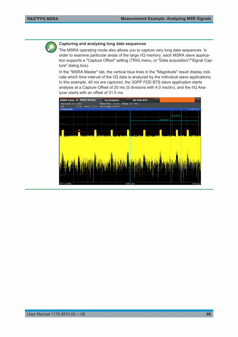
Measurement Example: Analyzing MSR SignalsR&S®FPS MSRA
68User Manual 1176.8574.02 ─ 08
Capturing and analyzing long data sequencesThe MSRA operating mode also allows you to capture very long data sequences. Inorder to examine particular areas of the large I/Q memory, each MSRA slave applica-tion supports a "Capture Offset" setting (TRIG menu, or "Data acquisition"/"Signal Cap-ture" dialog box).In the "MSRA Master" tab, the vertical blue lines in the "Magnitude" result display indi-cate which time interval of the I/Q data is analyzed by the individual slave applications.In this example, 40 ms are captured, the 3GPP FDD BTS slave application startsanalysis at a Capture Offset of 20 ms (5 divisions with 4.0 ms/div), and the I/Q Ana-lyzer starts with an offset of 31.5 ms.

Remote Commands to Perform Measurements in MSRA ModeR&S®FPS MSRA
69User Manual 1176.8574.02 ─ 08
11 Remote Commands to Perform Measure-ments in MSRA ModeThe following commands are specific to performing measurements in MSRA mode in aremote environment. Generally, the remote commands are identical to those used inSpectrum mode as described in the R&S FPS User Manual. However, some restric-tions or conditions may apply to specific commands (see also Chapter 6, "MSRABasics", on page 24).
You must always switch to MSRA mode before executing any MSRA-specific com-mands (using INST:MODE MSR).
It is assumed that the R&S FPS has already been set up for remote control in a net-work as described in the R&S FPS User Manual.
Note that basic tasks that are also performed in the base unit in the same way are notdescribed here. For a description of such tasks, see the R&S FPS User Manual.In particular, this includes:● Managing Settings and Results, i.e. storing and loading settings and result data● Basic instrument configuration, e.g. checking the system configuration, customizing
the screen layout, or configuring networks and remote operation● Using the common status registers
The following tasks specific to MSRA mode are described here:
● Introduction............................................................................................................. 69● Common Suffixes....................................................................................................74● Activating MSRA Measurements............................................................................ 75● Configuring MSRA Measurements..........................................................................80● Capturing Data and Performing Sweeps...............................................................104● Retrieving Results.................................................................................................110● Querying the Status Registers.............................................................................. 114● Analyzing MSRA Measurements.......................................................................... 117● Commands Specific to MSRA Slave Applications................................................ 118● Programming Example: Analyzing MSR Signals.................................................. 120
11.1 Introduction
Commands are program messages that a controller (e.g. a PC) sends to the instru-ment or software. They operate its functions ('setting commands' or 'events') andrequest information ('query commands'). Some commands can only be used in oneway, others work in two ways (setting and query). If not indicated otherwise, the com-mands can be used for settings and queries.
Introduction

Remote Commands to Perform Measurements in MSRA ModeR&S®FPS MSRA
70User Manual 1176.8574.02 ─ 08
The syntax of a SCPI command consists of a header and, in most cases, one or moreparameters. To use a command as a query, you have to append a question mark afterthe last header element, even if the command contains a parameter.
A header contains one or more keywords, separated by a colon. Header and parame-ters are separated by a "white space" (ASCII code 0 to 9, 11 to 32 decimal, e.g. blank).If there is more than one parameter for a command, these are separated by a commafrom one another.
Only the most important characteristics that you need to know when working with SCPIcommands are described here. For a more complete description, refer to the UserManual of the R&S FPS.
Remote command examplesNote that some remote command examples mentioned in this general introduction maynot be supported by this particular application.
11.1.1 Conventions used in Descriptions
Note the following conventions used in the remote command descriptions:● Command usage
If not specified otherwise, commands can be used both for setting and for queryingparameters.If a command can be used for setting or querying only, or if it initiates an event, theusage is stated explicitly.
● Parameter usageIf not specified otherwise, a parameter can be used to set a value and it is theresult of a query.Parameters required only for setting are indicated as Setting parameters.Parameters required only to refine a query are indicated as Query parameters.Parameters that are only returned as the result of a query are indicated as Returnvalues.
● ConformityCommands that are taken from the SCPI standard are indicated as SCPI con-firmed. All commands used by the R&S FPS follow the SCPI syntax rules.
● Asynchronous commandsA command which does not automatically finish executing before the next com-mand starts executing (overlapping command) is indicated as an Asynchronouscommand.
● Reset values (*RST)Default parameter values that are used directly after resetting the instrument (*RSTcommand) are indicated as *RST values, if available.
● Default unitThis is the unit used for numeric values if no other unit is provided with the parame-ter.
● Manual operation
Introduction

Remote Commands to Perform Measurements in MSRA ModeR&S®FPS MSRA
71User Manual 1176.8574.02 ─ 08
If the result of a remote command can also be achieved in manual operation, a linkto the description is inserted.
11.1.2 Long and Short Form
The keywords have a long and a short form. You can use either the long or the shortform, but no other abbreviations of the keywords.
The short form is emphasized in upper case letters. Note however, that this emphasisonly serves the purpose to distinguish the short from the long form in the manual. Forthe instrument, the case does not matter.
Example: SENSe:FREQuency:CENTer is the same as SENS:FREQ:CENT.
11.1.3 Numeric Suffixes
Some keywords have a numeric suffix if the command can be applied to multipleinstances of an object. In that case, the suffix selects a particular instance (e.g. a mea-surement window).
Numeric suffixes are indicated by angular brackets (<n>) next to the keyword.
If you don't quote a suffix for keywords that support one, a 1 is assumed.
Example: DISPlay[:WINDow<1...4>]:ZOOM:STATe enables the zoom in a particular mea-surement window, selected by the suffix at WINDow.
DISPlay:WINDow4:ZOOM:STATe ON refers to window 4.
11.1.4 Optional Keywords
Some keywords are optional and are only part of the syntax because of SCPI compli-ance. You can include them in the header or not.
Note that if an optional keyword has a numeric suffix and you need to use the suffix,you have to include the optional keyword. Otherwise, the suffix of the missing keywordis assumed to be the value 1.
Optional keywords are emphasized with square brackets.
Introduction

Remote Commands to Perform Measurements in MSRA ModeR&S®FPS MSRA
72User Manual 1176.8574.02 ─ 08
Example: Without a numeric suffix in the optional keyword:[SENSe:]FREQuency:CENTer is the same as FREQuency:CENTerWith a numeric suffix in the optional keyword:DISPlay[:WINDow<1...4>]:ZOOM:STATeDISPlay:ZOOM:STATe ON enables the zoom in window 1 (no suffix).
DISPlay:WINDow4:ZOOM:STATe ON enables the zoom in window 4.
11.1.5 Alternative Keywords
A vertical stroke indicates alternatives for a specific keyword. You can use both key-words to the same effect.
Example: [SENSe:]BANDwidth|BWIDth[:RESolution]In the short form without optional keywords, BAND 1MHZ would have the same effectas BWID 1MHZ.
11.1.6 SCPI Parameters
Many commands feature one or more parameters.
If a command supports more than one parameter, these are separated by a comma.
Example: LAYout:ADD:WINDow Spectrum,LEFT,MTABle
Parameters may have different forms of values.
● Numeric Values.......................................................................................................72● Boolean...................................................................................................................73● Character Data........................................................................................................74● Character Strings.................................................................................................... 74● Block Data...............................................................................................................74
11.1.6.1 Numeric Values
Numeric values can be entered in any form, i.e. with sign, decimal point or exponent. Incase of physical quantities, you can also add the unit. If the unit is missing, the com-mand uses the basic unit.
Example: With unit: SENSe:FREQuency:CENTer 1GHZWithout unit: SENSe:FREQuency:CENTer 1E9 would also set a frequency of 1 GHz.
Introduction

Remote Commands to Perform Measurements in MSRA ModeR&S®FPS MSRA
73User Manual 1176.8574.02 ─ 08
Values exceeding the resolution of the instrument are rounded up or down.
If the number you have entered is not supported (e.g. in case of discrete steps), thecommand returns an error.
Instead of a number, you can also set numeric values with a text parameter in specialcases.
● MIN/MAXDefines the minimum or maximum numeric value that is supported.
● DEFDefines the default value.
● UP/DOWNIncreases or decreases the numeric value by one step. The step size depends onthe setting. In some cases you can customize the step size with a correspondingcommand.
Querying numeric values
When you query numeric values, the system returns a number. In case of physicalquantities, it applies the basic unit (e.g. Hz in case of frequencies). The number of dig-its after the decimal point depends on the type of numeric value.
Example: Setting: SENSe:FREQuency:CENTer 1GHZQuery: SENSe:FREQuency:CENTer? would return 1E9
In some cases, numeric values may be returned as text.
● INF/NINFInfinity or negative infinity. Represents the numeric values 9.9E37 or -9.9E37.
● NANNot a number. Represents the numeric value 9.91E37. NAN is returned in case oferrors.
11.1.6.2 Boolean
Boolean parameters represent two states. The "ON" state (logically true) is represen-ted by "ON" or a numeric value 1. The "OFF" state (logically untrue) is represented by"OFF" or the numeric value 0.
Querying Boolean parameters
When you query Boolean parameters, the system returns either the value 1 ("ON") orthe value 0 ("OFF").
Example: Setting: DISPlay:WINDow:ZOOM:STATe ONQuery: DISPlay:WINDow:ZOOM:STATe? would return 1
Introduction

Remote Commands to Perform Measurements in MSRA ModeR&S®FPS MSRA
74User Manual 1176.8574.02 ─ 08
11.1.6.3 Character Data
Character data follows the syntactic rules of keywords. You can enter text using a shortor a long form. For more information see Chapter 11.1.2, "Long and Short Form",on page 71.
Querying text parameters
When you query text parameters, the system returns its short form.
Example: Setting: SENSe:BANDwidth:RESolution:TYPE NORMalQuery: SENSe:BANDwidth:RESolution:TYPE? would return NORM
11.1.6.4 Character Strings
Strings are alphanumeric characters. They have to be in straight quotation marks. Youcan use a single quotation mark ( ' ) or a double quotation mark ( " ).
Example: INSTRument:DELete 'Spectrum'
11.1.6.5 Block Data
Block data is a format which is suitable for the transmission of large amounts of data.
The ASCII character # introduces the data block. The next number indicates how manyof the following digits describe the length of the data block. In the example the 4 follow-ing digits indicate the length to be 5168 bytes. The data bytes follow. During the trans-mission of these data bytes all end or other control signs are ignored until all bytes aretransmitted. #0 specifies a data block of indefinite length. The use of the indefinite for-mat requires an NL^END message to terminate the data block. This format is usefulwhen the length of the transmission is not known or if speed or other considerationsprevent segmentation of the data into blocks of definite length.
11.2 Common Suffixes
In the MSRA operating mode, the following common suffixes are used in remote com-mands:
Table 11-1: Common suffixes used in remote commands in the MSRA operating mode
Suffix Value range Description
<m> 1 to 16 Marker
<n> 1 to 6 Window (in the currently selected channel)
<t> 1 to 6 Trace
Common Suffixes

Remote Commands to Perform Measurements in MSRA ModeR&S®FPS MSRA
75User Manual 1176.8574.02 ─ 08
11.3 Activating MSRA Measurements
MSRA measurements requires a special operating mode on the R&S FPS. A measure-ment is started immediately with the default settings.
The special MSRA Master measurement channel is of the channel type "IQ" and isreferred to by the channel name "MSRA Master". This channel cannot be replaced,deleted, or renamed.
INSTrument:CREate:DUPLicate........................................................................................ 75INSTrument:CREate[:NEW].............................................................................................. 75INSTrument:CREate:REPLace..........................................................................................76INSTrument:DELete......................................................................................................... 76INSTrument:LIST?........................................................................................................... 77INSTrument:MODE.......................................................................................................... 78INSTrument:REName.......................................................................................................78INSTrument[:SELect]........................................................................................................78SYSTem:PRESet:COMPatible...........................................................................................79SYSTem:PRESet:CHANnel[:EXEC]...................................................................................79
INSTrument:CREate:DUPLicate
This command duplicates the currently selected channel, i.e creates a new channel ofthe same type and with the identical measurement settings. The name of the newchannel is the same as the copied channel, extended by a consecutive number (e.g."IQAnalyzer" -> "IQAnalyzer 2").
The channel to be duplicated must be selected first using the INST:SEL command.
This command is not available if the MSRA Master channel is selected.
Example: INST:SEL 'IQAnalyzer'INST:CRE:DUPLDuplicates the channel named 'IQAnalyzer' and creates a newchannel named 'IQAnalyzer2'.
Usage: Event
INSTrument:CREate[:NEW] <ChannelType>, <ChannelName>
This command adds an additional channel.
The number of channels you can configure at the same time depends on availablememory.
Parameters:<ChannelType> Channel type of the new channel.
For a list of available channel types see INSTrument:LIST?on page 77.
Activating MSRA Measurements

Remote Commands to Perform Measurements in MSRA ModeR&S®FPS MSRA
76User Manual 1176.8574.02 ─ 08
<ChannelName> String containing the name of the channel. The channel name isdisplayed as the tab label for the channel.Note: If the specified name for a new channel already exists, thedefault name, extended by a sequential number, is used for thenew channel (see INSTrument:LIST? on page 77).
Example: INST:CRE IQ, 'IQAnalyzer2'Adds an additional I/Q Analyzer channel named "IQAnalyzer2".
Manual operation: See "New Channel" on page 21
INSTrument:CREate:REPLace <ChannelName1>,<ChannelType>,<ChannelName2>
This command replaces a channel with another one.
Setting parameters: <ChannelName1> String containing the name of the channel you want to replace.
<ChannelType> Channel type of the new channel.For a list of available channel types see INSTrument:LIST?on page 77.
<ChannelName2> String containing the name of the new channel.Note: If the specified name for a new channel already exists, thedefault name, extended by a sequential number, is used for thenew channel (see INSTrument:LIST? on page 77).
Example: INST:CRE:REPL 'IQAnalyzer2',IQ,'IQAnalyzer'Replaces the channel named "IQAnalyzer2" by a new channel oftype "IQ Analyzer" named "IQAnalyzer".
Usage: Setting only
Manual operation: See "Replace Current Channel" on page 21
INSTrument:DELete <ChannelName>
This command deletes a channel.
If you delete the last channel, the default "Spectrum" channel is activated.
Parameters:<ChannelName> String containing the name of the channel you want to delete.
A channel must exist in order to be able delete it.
Example: INST:DEL 'IQAnalyzer4'Deletes the channel with the name 'IQAnalyzer4'.
Usage: Event
Manual operation: See "Closing an application" on page 22
Activating MSRA Measurements

Remote Commands to Perform Measurements in MSRA ModeR&S®FPS MSRA
77User Manual 1176.8574.02 ─ 08
INSTrument:LIST?
This command queries all active channels. This is useful in order to obtain the namesof the existing channels, which are required in order to replace or delete the channels.
Return values: <ChannelType>,<ChannelName>
For each channel, the command returns the channel type andchannel name (see tables below).Tip: to change the channel name, use the INSTrument:REName command.
Example: INST:LIST?Result for 3 channels:'ADEM','Analog Demod','IQ','IQAnalyzer','IQ','IQ Analyzer2'
Usage: Query only
Table 11-2: Available channel types and default channel names in MSRA mode
Slave application <ChannelType> Parameter Default Channel Name*)
1xEV-DO BTS (R&S FPS-K84)
BDO 1xEV-DO BTS
3GPP FDD BTS(R&S FPS-K72)
BWCD 3G FDD BTS
Analog Demodulation(R&S FPS-K7)
ADEM Analog Demod
cdma2000 BTS (R&S FPS-K82)
BC2K CDMA2000 BTS
GSM (R&S FPS-K10) GSM GSM
I/Q Analyzer IQ IQ Analyzer
LTE (R&S FPS-K10x) LTE LTE
Pulse (R&S FPS-K6) PULSE Pulse
TD-SCDMA BTS(R&S FPS-K76)
BTDS TD-SCDMA BTS
Transient Analysis(R&S FPS-K60)
TA Transient Analysis
VSA (R&S FPS-K70) DDEM VSA
WLAN (R&S FPS-K91) WLAN WLAN
Note: the default channel name is also listed in the table. If the specified name for a new channel alreadyexists, the default name, extended by a sequential number, is used for the new channel.
Activating MSRA Measurements

Remote Commands to Perform Measurements in MSRA ModeR&S®FPS MSRA
78User Manual 1176.8574.02 ─ 08
INSTrument:MODE <OpMode>
The operating mode of the R&S FPS determines which applications are available andactive. Whenever you change the operating mode, the currently active channels areclosed. The default operating mode is Signal and Spectrum Analyzer mode, however,the presetting can be changed.
(See the "Instrument Setup" chapter in the R&S FPS User Manual).
Parameters:<OpMode> SANalyzer
Signal and Spectrum Analyzer modeMSRanalyzerMulti-Standard Radio Analysis (MSRA) mode*RST: SAN
Example: INST:MODE MSRSwitches to Multi-Standard Radio Analysis (MSRA) mode.
Manual operation: See "Switching the operating mode" on page 21
INSTrument:REName <ChannelName1>, <ChannelName2>
This command renames a channel.
Parameters:<ChannelName1> String containing the name of the channel you want to rename.
<ChannelName2> String containing the new channel name.Note that you cannot assign an existing channel name to a newchannel; this will cause an error.
Example: INST:REN 'IQAnalyzer2','IQAnalyzer3'Renames the channel with the name 'IQAnalyzer2' to 'IQAna-lyzer3'.
Usage: Setting only
INSTrument[:SELect] <ChannelType> | <ChannelName>
This command activates a new channel with the defined channel type, or selects anexisting channel with the specified name.
Also see
● INSTrument:CREate[:NEW] on page 75
Parameters:<ChannelType> Channel type of the new channel.
For a list of available channel types see INSTrument:LIST?on page 77.
<ChannelName> String containing the name of the channel.
Activating MSRA Measurements

Remote Commands to Perform Measurements in MSRA ModeR&S®FPS MSRA
79User Manual 1176.8574.02 ─ 08
Example: INST IQActivates a channel for the I/Q Analyzer application (evaluationmode).INST 'MyIQSpectrum'Selects the channel named 'MyIQSpectrum' (for example beforeexecuting further commands for that channel).
Manual operation: See "I/Q Analyzer" on page 19See "Pulse Measurements" on page 19See "GSM" on page 19See "3G FDD BTS" on page 19See "TD-SCDMA BTS" on page 19See "cdma2000 BTS" on page 20See "1xEV-DO BTS" on page 20See "LTE DL" on page 20See "Selecting an MSRA slave application" on page 21See "New Channel" on page 21
SYSTem:PRESet:COMPatible <OpMode>
This command defines the operating mode that is activated when you switch on theR&S FPS or press the PRESET key.
For details on operating modes see Chapter 5, "Applications and Operating Modes",on page 17.
Parameters:<OpMode> SANalyzer
(Default:)Defines Signal and Spectrum Analyzer operating mode as thepresetting.MSRADefines Multi-Standard Radio Analysis (MSRA) as the presetdefault operating mode.
SYSTem:PRESet:CHANnel[:EXEC]
This command restores the default instrument settings in the current channel.
Use INST:SEL to select the channel.
Example: INST:SEL 'Spectrum2'Selects the channel for "Spectrum2".SYST:PRES:CHAN:EXECRestores the factory default settings to the "Spectrum2" channel.
Usage: Event
Manual operation: See "Preset Channel" on page 32
Activating MSRA Measurements

Remote Commands to Perform Measurements in MSRA ModeR&S®FPS MSRA
80User Manual 1176.8574.02 ─ 08
11.4 Configuring MSRA Measurements
● Configuring Input/Output and Frontend Settings.................................................... 80● Triggering................................................................................................................90● Configuring Data Acquisition...................................................................................95● Adjusting Settings Automatically...........................................................................101
11.4.1 Configuring Input/Output and Frontend Settings
The following commands are required to define input, output and frontend settings. Anysettings related to data acquisition or data output are only available for the MSRA Mas-ter.
● RF Input.................................................................................................................. 80● Configuring the Vertical Axis (Amplitude, Scaling)..................................................82● Frequency............................................................................................................... 88● Configuring the Outputs.......................................................................................... 89
11.4.1.1 RF Input
INPut:COUPling...............................................................................................................80INPut:DPATh...................................................................................................................80INPut:FILTer:YIG[:STATe]................................................................................................ 81INPut:IMPedance.............................................................................................................81INPut:IMPedance:PTYPe..................................................................................................81INPut:SELect...................................................................................................................82
INPut:COUPling <CouplingType>
This command selects the coupling type of the RF input.
Parameters:<CouplingType> AC
AC couplingDCDC coupling*RST: AC
Example: INP:COUP DCManual operation: See " Input Coupling " on page 34
INPut:DPATh <State>
Enables or disables the use of the direct path for frequencies close to 0 Hz.
Configuring MSRA Measurements

Remote Commands to Perform Measurements in MSRA ModeR&S®FPS MSRA
81User Manual 1176.8574.02 ─ 08
Parameters:<State> AUTO | 1
(Default) the direct path is used automatically for frequenciesclose to 0 Hz.OFF | 0The analog mixer path is always used.*RST: 1
Example: INP:DPAT OFF
INPut:FILTer:YIG[:STATe] <State>
This command turns the YIG-preselector on and off.
Note the special conditions and restrictions for the YIG-preselector described in " YIG-Preselector " on page 35.
Parameters:<State> ON | OFF | 0 | 1
*RST: 1 (0 for I/Q Analyzer, GSM, VSA, Pulse, Amplifiermeasurements)
Example: INP:FILT:YIG OFFDeactivates the YIG-preselector.
Manual operation: See " YIG-Preselector " on page 35
INPut:IMPedance <Impedance>
This command selects the nominal input impedance of the RF input. In some applica-tions, only 50 Ω are supported.
Parameters:<Impedance> 50 | 75
numeric valueUser-defined impedance from 50 Ohm to 100000000 Ohm(=100 MOhm)User-defined values are only available for the Spectrum applica-tion, the I/Q Analyzer (and thus MSRA mode, Master only) andsome optional applications.*RST: 50 Ω
Example: INP:IMP 75Manual operation: See " Impedance " on page 34
See " Impedance " on page 34
INPut:IMPedance:PTYPe <PadType>
Defines the type of matching pad used for impedance conversion for RF input.
Configuring MSRA Measurements

Remote Commands to Perform Measurements in MSRA ModeR&S®FPS MSRA
82User Manual 1176.8574.02 ─ 08
Parameters:<PadType> SRESistor | MLPad
SRESistorSeries-RMLPadMinimum Loss Pad*RST: SRESistor
Example: INP:IMP 100INP:IMP:PTYP MLP
Manual operation: See " Impedance " on page 34
INPut:SELect <Source>
This command selects the signal source for measurements, i.e. it defines which con-nector is used to input data to the R&S FPS.
Parameters:<Source> RF
Radio Frequency ("RF INPUT" connector)*RST: RF
Manual operation: See " Radio Frequency State " on page 33
11.4.1.2 Configuring the Vertical Axis (Amplitude, Scaling)
The following commands are required to configure the amplitude and vertical axis set-tings in a remote environment.
● Amplitude Settings.................................................................................................. 82● Configuring the Attenuation.....................................................................................83● Configuring a Preamplifier.......................................................................................85● Scaling the Y-Axis...................................................................................................86
Amplitude Settings
Useful commands for amplitude configuration described elsewhere:
● [SENSe:]ADJust:LEVel on page 104
Remote commands exclusive to amplitude configuration:
CALCulate<n>:MARKer<m>:FUNCtion:REFerence.............................................................82DISPlay[:WINDow<n>]:TRACe<t>:Y[:SCALe]:RLEVel......................................................... 83DISPlay[:WINDow<n>]:TRACe<t>:Y[:SCALe]:RLEVel:OFFSet............................................. 83
CALCulate<n>:MARKer<m>:FUNCtion:REFerence
This command matches the reference level to the power level of a marker.
Configuring MSRA Measurements

Remote Commands to Perform Measurements in MSRA ModeR&S®FPS MSRA
83User Manual 1176.8574.02 ─ 08
If you use the command in combination with a delta marker, that delta marker is turnedinto a normal marker.
Suffix: <n>
.Window
<m> Marker
Example: CALC:MARK2:FUNC:REFSets the reference level to the level of marker 2.
Usage: Event
DISPlay[:WINDow<n>]:TRACe<t>:Y[:SCALe]:RLEVel <ReferenceLevel>
This command defines the reference level (for all traces in all windows).
Suffix: <n>, <t>
.irrelevant
Example: DISP:TRAC:Y:RLEV -60dBmManual operation: See " Reference Level " on page 35
DISPlay[:WINDow<n>]:TRACe<t>:Y[:SCALe]:RLEVel:OFFSet <Offset>
This command defines a reference level offset (for all traces in all windows).
Suffix: <n>, <t>
.irrelevant
Parameters:<Offset> Range: -200 dB to 200 dB
*RST: 0dB
Example: DISP:TRAC:Y:RLEV:OFFS -10dBManual operation: See " Shifting the Display ( Offset )" on page 36
Configuring the Attenuation
INPut:ATTenuation...........................................................................................................83INPut:ATTenuation:AUTO.................................................................................................84INPut:ATTenuation:AUTO:MODE...................................................................................... 84INPut:EATT.....................................................................................................................84INPut:EATT:AUTO........................................................................................................... 85INPut:EATT:STATe..........................................................................................................85
INPut:ATTenuation <Attenuation>
This command defines the total attenuation for RF input.
Configuring MSRA Measurements

Remote Commands to Perform Measurements in MSRA ModeR&S®FPS MSRA
84User Manual 1176.8574.02 ─ 08
If you set the attenuation manually, it is no longer coupled to the reference level, butthe reference level is coupled to the attenuation. Thus, if the current reference level isnot compatible with an attenuation that has been set manually, the command alsoadjusts the reference level.
Parameters:<Attenuation> Range: see data sheet
Increment: 5 dB (with optional electr. attenuator: 1 dB)*RST: 10 dB (AUTO is set to ON)
Example: INP:ATT 30dBDefines a 30 dB attenuation and decouples the attenuation fromthe reference level.
Manual operation: See " Attenuation Mode / Value " on page 36
INPut:ATTenuation:AUTO <State>
This command couples or decouples the attenuation to the reference level. Thus, whenthe reference level is changed, the R&S FPS determines the signal level for optimalinternal data processing and sets the required attenuation accordingly.
Parameters:<State> ON | OFF | 0 | 1
*RST: 1
Example: INP:ATT:AUTO ONCouples the attenuation to the reference level.
Manual operation: See " Attenuation Mode / Value " on page 36
INPut:ATTenuation:AUTO:MODE <OptMode>
Selects the priority for signal processing after the RF attenuation has been applied.
Parameters:<OptMode> LNOise | LDIStortion
LNOiseOptimized for high sensitivity and low noise levelsLDIStortionOptimized for low distortion by avoiding intermodulation*RST: LDIStortion
Example: INP:ATT:AUTO:MODE LNO
INPut:EATT <Attenuation>
This command defines an electronic attenuation manually. Automatic mode must beswitched off (INP:EATT:AUTO OFF, see INPut:EATT:AUTO on page 85).
If the current reference level is not compatible with an attenuation that has been setmanually, the command also adjusts the reference level.
Configuring MSRA Measurements

Remote Commands to Perform Measurements in MSRA ModeR&S®FPS MSRA
85User Manual 1176.8574.02 ─ 08
Parameters:<Attenuation> attenuation in dB
Range: see data sheetIncrement: 1 dB*RST: 0 dB (OFF)
Example: INP:EATT:AUTO OFFINP:EATT 10 dB
Manual operation: See " Using Electronic Attenuation " on page 36
INPut:EATT:AUTO <State>
This command turns automatic selection of the electronic attenuation on and off.
If on, electronic attenuation reduces the mechanical attenuation whenever possible.
Parameters:<State> 1 | 0 | ON | OFF
1 | ON0 | OFF*RST: 1
Example: INP:EATT:AUTO OFFManual operation: See " Using Electronic Attenuation " on page 36
INPut:EATT:STATe <State>
This command turns the electronic attenuator on and off.
Parameters:<State> 1 | 0 | ON | OFF
1 | ON0 | OFF*RST: 0
Example: INP:EATT:STAT ONSwitches the electronic attenuator into the signal path.
Manual operation: See " Using Electronic Attenuation " on page 36
Configuring a Preamplifier
INPut:GAIN:STATe.......................................................................................................... 85
INPut:GAIN:STATe <State>
This command turns the preamplifier on and off.
If activated, the input signal is amplified by 20 dB.
If option R&S FPS-B22 is installed, the preamplifier is only active below 7 GHz.
Configuring MSRA Measurements

Remote Commands to Perform Measurements in MSRA ModeR&S®FPS MSRA
86User Manual 1176.8574.02 ─ 08
If option R&S FPS-B24 is installed, the preamplifier is active for all frequencies.
Parameters:<State> ON | OFF | 1 | 0
*RST: 0
Example: INP:GAIN:STAT ONSwitches on 20 dB preamplification.
Manual operation: See " Preamplifier (option B22/B24)" on page 37
Scaling the Y-Axis
DISPlay[:WINDow<n>]:TRACe<t>:Y[:SCALe]..................................................................... 86DISPlay[:WINDow<n>]:TRACe<t>:Y[:SCALe]:AUTO ONCE................................................. 86DISPlay[:WINDow<n>]:TRACe<t>:Y[:SCALe]:MODE...........................................................86DISPlay[:WINDow<n>]:TRACe<t>:Y[:SCALe]:PDIVision...................................................... 87DISPlay[:WINDow<n>]:TRACe<t>:Y[:SCALe]:RPOSition..................................................... 87DISPlay[:WINDow<n>]:TRACe<t>:Y:SPACing.................................................................... 87
DISPlay[:WINDow<n>]:TRACe<t>:Y[:SCALe] <Range>
This command defines the display range of the y-axis (for all traces).
Suffix: <n>
.Window
<t> irrelevant
Example: DISP:TRAC:Y 110dBManual operation: See " Range " on page 38
See " Y-Axis Max " on page 39
DISPlay[:WINDow<n>]:TRACe<t>:Y[:SCALe]:AUTO ONCE
Automatic scaling of the y-axis is performed once, then switched off again (for alltraces).
Suffix: <n>
.Window
<t> irrelevant
DISPlay[:WINDow<n>]:TRACe<t>:Y[:SCALe]:MODE <Mode>
This command selects the type of scaling of the y-axis (for all traces).
When the display update during remote control is off, this command has no immediateeffect.
Suffix: <n>
.Window
<t> irrelevant
Configuring MSRA Measurements

Remote Commands to Perform Measurements in MSRA ModeR&S®FPS MSRA
87User Manual 1176.8574.02 ─ 08
Parameters:<Mode> ABSolute
absolute scaling of the y-axisRELativerelative scaling of the y-axis*RST: ABSolute
Example: DISP:TRAC:Y:MODE RELManual operation: See " Scaling " on page 38
DISPlay[:WINDow<n>]:TRACe<t>:Y[:SCALe]:PDIVision <Value>
This remote command determines the grid spacing on the Y-axis for all diagrams,where possible.
Suffix: <n>
.Window
<t> irrelevant
Parameters:<Value> numeric value WITHOUT UNIT (unit according to the result dis-
play)Defines the range per division (total range = 10*<Value>)*RST: depends on the result display
Example: DISP:TRAC:Y:PDIV 10Sets the grid spacing to 10 units (e.g. dB) per division
DISPlay[:WINDow<n>]:TRACe<t>:Y[:SCALe]:RPOSition <Position>
This command defines the vertical position of the reference level on the display grid(for all traces).
The R&S FPS adjusts the scaling of the y-axis accordingly.
Suffix: <n>
.Window
<t> irrelevant
Example: DISP:TRAC:Y:RPOS 50PCTManual operation: See " Ref Level Position " on page 38
DISPlay[:WINDow<n>]:TRACe<t>:Y:SPACing <ScalingType>
This command selects the scaling of the y-axis (for all traces, <t> is irrelevant).
Suffix: <n>
.Window
<t> Trace
Configuring MSRA Measurements

Remote Commands to Perform Measurements in MSRA ModeR&S®FPS MSRA
88User Manual 1176.8574.02 ─ 08
Parameters:<ScalingType> LOGarithmic
Logarithmic scaling.LINearLinear scaling in %.LDBLinear scaling in the specified unit.PERCentLinear scaling in %.*RST: LOGarithmic
Example: DISP:TRAC:Y:SPAC LINSelects linear scaling in %.
Manual operation: See " Scaling " on page 38
11.4.1.3 Frequency
[SENSe:]FREQuency:CENTer...........................................................................................88[SENSe:]FREQuency:CENTer:STEP................................................................................. 88[SENSe:]FREQuency:OFFSet........................................................................................... 89
[SENSe:]FREQuency:CENTer <Frequency>
This command defines the center frequency.
Parameters:<Frequency> The allowed range and fmax is specified in the data sheet.
UPIncreases the center frequency by the step defined using the[SENSe:]FREQuency:CENTer:STEP command.
DOWNDecreases the center frequency by the step defined using the[SENSe:]FREQuency:CENTer:STEP command.
*RST: fmax/2Default unit: Hz
Example: FREQ:CENT 100 MHzFREQ:CENT:STEP 10 MHzFREQ:CENT UPSets the center frequency to 110 MHz.
Manual operation: See " Center Frequency " on page 39
[SENSe:]FREQuency:CENTer:STEP <StepSize>
This command defines the center frequency step size.
Configuring MSRA Measurements

Remote Commands to Perform Measurements in MSRA ModeR&S®FPS MSRA
89User Manual 1176.8574.02 ─ 08
You can increase or decrease the center frequency quickly in fixed steps using theSENS:FREQ UP AND SENS:FREQ DOWN commands, see [SENSe:]FREQuency:CENTer on page 88.
Parameters:<StepSize> fmax is specified in the data sheet.
Range: 1 to fMAX*RST: 0.1 x spanDefault unit: Hz
Example: //Set the center frequency to 110 MHz.FREQ:CENT 100 MHzFREQ:CENT:STEP 10 MHzFREQ:CENT UP
Manual operation: See " Center Frequency Stepsize " on page 40
[SENSe:]FREQuency:OFFSet <Offset>
This command defines a frequency offset.
If this value is not 0 Hz, the application assumes that the input signal was frequencyshifted outside the application. All results of type "frequency" will be corrected for thisshift numerically by the application.
See also " Frequency Offset " on page 40.
Note: In MSRA mode, the setting command is only available for the MSRA Master. ForMSRA slave applications, only the query command is available.
Parameters:<Offset> Range: -100 GHz to 100 GHz
*RST: 0 Hz
Example: FREQ:OFFS 1GHZManual operation: See " Frequency Offset " on page 40
11.4.1.4 Configuring the Outputs
The following commands are required to provide output from the R&S FPS.
Configuring trigger input/output is described in Chapter 11.4.2.2, "Configuring the Trig-ger Output", on page 94.
DIAGnostic:SERVice:NSOurce..........................................................................................89
DIAGnostic:SERVice:NSOurce <State>
This command turns the 28 V supply of the BNC connector labeled NOISE SOURCECONTROL on the R&S FPS on and off.
Configuring MSRA Measurements

Remote Commands to Perform Measurements in MSRA ModeR&S®FPS MSRA
90User Manual 1176.8574.02 ─ 08
Suffix: <n>
.Window
Parameters:<State> ON | OFF | 1 | 0
*RST: 0
Example: DIAG:SERV:NSO ONManual operation: See "Noise Source Control" on page 53
11.4.2 Triggering
The following remote commands are required to configure a triggered measurement ina remote environment. These commands are only available for the MSRA Masterchannel. More details are described for manual operation in Chapter 7.5, "Trigger Set-tings", on page 40.
*OPC should be used after requesting data. This will hold off any subsequent changesto the selected trigger source, until after the sweep is completed and the data isreturned.
● Configuring the Triggering Conditions.....................................................................90● Configuring the Trigger Output................................................................................94
11.4.2.1 Configuring the Triggering Conditions
The following commands are required to configure a triggered measurement.
TRIGger[:SEQuence]:DTIMe.............................................................................................90TRIGger[:SEQuence]:HOLDoff[:TIME]................................................................................91TRIGger[:SEQuence]:IFPower:HOLDoff............................................................................. 91TRIGger[:SEQuence]:IFPower:HYSTeresis........................................................................ 91TRIGger[:SEQuence]:LEVel[:EXTernal<port>].................................................................... 91TRIGger[:SEQuence]:LEVel:IFPower.................................................................................92TRIGger[:SEQuence]:LEVel:IQPower................................................................................ 92TRIGger[:SEQuence]:LEVel:RFPower................................................................................92TRIGger[:SEQuence]:SLOPe............................................................................................ 93TRIGger[:SEQuence]:SOURce..........................................................................................93
TRIGger[:SEQuence]:DTIMe <DropoutTime>
Defines the time the input signal must stay below the trigger level before a trigger isdetected again.
Parameters:<DropoutTime> Dropout time of the trigger.
Range: 0 s to 10.0 s*RST: 0 s
Configuring MSRA Measurements

Remote Commands to Perform Measurements in MSRA ModeR&S®FPS MSRA
91User Manual 1176.8574.02 ─ 08
Manual operation: See " Drop-Out Time " on page 43
TRIGger[:SEQuence]:HOLDoff[:TIME] <Offset>
Defines the time offset between the trigger event and the start of the sweep.
Parameters:<Offset> *RST: 0 s
Example: TRIG:HOLD 500usManual operation: See "Trigger Offset" on page 43
TRIGger[:SEQuence]:IFPower:HOLDoff <Period>
This command defines the holding time before the next trigger event.
Note that this command can be used for any trigger source, not just IF Power(despite the legacy keyword).
Parameters:<Period> Range: 0 s to 10 s
*RST: 0 s
Example: TRIG:SOUR EXTSets an external trigger source.TRIG:IFP:HOLD 200 nsSets the holding time to 200 ns.
Manual operation: See " Trigger Holdoff " on page 44
TRIGger[:SEQuence]:IFPower:HYSTeresis <Hysteresis>
This command defines the trigger hysteresis, which is only available for "IF Power" trig-ger sources.
Parameters:<Hysteresis> Range: 3 dB to 50 dB
*RST: 3 dB
Example: TRIG:SOUR IFPSets the IF power trigger source.TRIG:IFP:HYST 10DBSets the hysteresis limit value.
Manual operation: See " Hysteresis " on page 44
TRIGger[:SEQuence]:LEVel[:EXTernal<port>] <TriggerLevel>
This command defines the level the external signal must exceed to cause a triggerevent.
Configuring MSRA Measurements

Remote Commands to Perform Measurements in MSRA ModeR&S®FPS MSRA
92User Manual 1176.8574.02 ─ 08
Suffix: <port>
.Selects the trigger port.1 = trigger port 1 (TRIG IN connector on rear panel)2 = trigger port 2 (TRIG AUX connector on rear panel)
Parameters:<TriggerLevel> Range: 0.5 V to 3.5 V
*RST: 1.4 V
Example: TRIG:LEV 2VManual operation: See " Trigger Level " on page 43
TRIGger[:SEQuence]:LEVel:IFPower <TriggerLevel>
This command defines the power level at the third intermediate frequency that must beexceeded to cause a trigger event. Note that any RF attenuation or preamplification isconsidered when the trigger level is analyzed. If defined, a reference level offset is alsoconsidered.
Parameters:<TriggerLevel> For details on available trigger levels and trigger bandwidths see
the data sheet.*RST: -10 dBm
Example: TRIG:LEV:IFP -30DBM
TRIGger[:SEQuence]:LEVel:IQPower <TriggerLevel>
This command defines the magnitude the I/Q data must exceed to cause a triggerevent. Note that any RF attenuation or preamplification is considered when the triggerlevel is analyzed.
Parameters:<TriggerLevel> Range: -130 dBm to 30 dBm
*RST: -20 dBm
Example: TRIG:LEV:IQP -30DBM
TRIGger[:SEQuence]:LEVel:RFPower <TriggerLevel>
This command defines the power level the RF input must exceed to cause a triggerevent. Note that any RF attenuation or preamplification is considered when the triggerlevel is analyzed. If defined, a reference level offset is also considered.
The input signal must be between 500 MHz and 8 GHz.
Parameters:<TriggerLevel> For details on available trigger levels and trigger bandwidths see
the data sheet.*RST: -20 dBm
Example: TRIG:LEV:RFP -30dBm
Configuring MSRA Measurements

Remote Commands to Perform Measurements in MSRA ModeR&S®FPS MSRA
93User Manual 1176.8574.02 ─ 08
TRIGger[:SEQuence]:SLOPe <Type>
Parameters:<Type> POSitive | NEGative
POSitiveTriggers when the signal rises to the trigger level (rising edge).NEGativeTriggers when the signal drops to the trigger level (falling edge).*RST: POSitive
Example: TRIG:SLOP NEGManual operation: See " Slope " on page 44
TRIGger[:SEQuence]:SOURce <Source>
This command selects the trigger source.
Note on external triggers:
If a measurement is configured to wait for an external trigger signal in a remote controlprogram, remote control is blocked until the trigger is received and the program cancontinue. Make sure this situation is avoided in your remote control programs.
Parameters:<Source> IMMediate
Free RunEXTernalTrigger signal from the TRIGGER IN connector.EXT2Trigger signal from the TRIGGER AUX connector.RFPowerFirst intermediate frequencyIFPowerSecond intermediate frequencyIQPowerMagnitude of sampled I/Q dataFor applications that process I/Q data, such as the I/Q Analyzeror optional applications.*RST: IMMediate
Example: TRIG:SOUR EXTSelects the external trigger input as source of the trigger signal
Manual operation: See "Trigger Source" on page 42See " Free Run " on page 42See "External Trigger 1/2" on page 42See " IF Power " on page 42See " RF Power " on page 43See " I/Q Power " on page 43
Configuring MSRA Measurements

Remote Commands to Perform Measurements in MSRA ModeR&S®FPS MSRA
94User Manual 1176.8574.02 ─ 08
11.4.2.2 Configuring the Trigger Output
The following commands are required to send the trigger signal to one of the variableTRIGGER INPUT/OUTPUT connectors on the R&S FPS.
OUTPut:TRIGger<port>:DIRection.....................................................................................94OUTPut:TRIGger<port>:LEVel.......................................................................................... 94OUTPut:TRIGger<port>:OTYPe........................................................................................ 95OUTPut:TRIGger<port>:PULSe:IMMediate.........................................................................95OUTPut:TRIGger<port>:PULSe:LENGth............................................................................ 95
OUTPut:TRIGger<port>:DIRection <Direction>
This command selects the trigger direction for trigger ports that serve as an input aswell as an output.
Suffix: <port>
.Selects the used trigger port.2 = TRG AUX
Parameters:<Direction> INPut
Port works as an input.OUTPutPort works as an output.*RST: INPut
Manual operation: See "Trigger 2" on page 45
OUTPut:TRIGger<port>:LEVel <Level>
This command defines the level of the (TTL compatible) signal generated at the triggeroutput.
This command works only if you have selected a user defined output with OUTPut:TRIGger<port>:OTYPe.
Suffix: <port>
.Selects the trigger port to which the output is sent.2 = TRG AUX
Parameters:<Level> HIGH
5 VLOW0 V*RST: LOW
Example: OUTP:TRIG2:LEV HIGHManual operation: See " Level " on page 45
Configuring MSRA Measurements

Remote Commands to Perform Measurements in MSRA ModeR&S®FPS MSRA
95User Manual 1176.8574.02 ─ 08
OUTPut:TRIGger<port>:OTYPe <OutputType>
This command selects the type of signal generated at the trigger output.
Suffix: <port>
.Selects the trigger port to which the output is sent.2 = TRG AUX
Parameters:<OutputType> DEVice
Sends a trigger signal when the R&S FPS has triggered inter-nally.TARMedSends a trigger signal when the trigger is armed and ready foran external trigger event.UDEFinedSends a user defined trigger signal. For more information seeOUTPut:TRIGger<port>:LEVel.
*RST: DEVice
Manual operation: See " Output Type " on page 45
OUTPut:TRIGger<port>:PULSe:IMMediate
This command generates a pulse at the trigger output.
Suffix: <port>
.Selects the trigger port to which the output is sent.2 = TRG AUX
Usage: Event
Manual operation: See " Send Trigger " on page 46
OUTPut:TRIGger<port>:PULSe:LENGth <Length>
This command defines the length of the pulse generated at the trigger output.
Suffix: <port>
.Selects the trigger port to which the output is sent.2 = TRG AUX
Parameters:<Length> Pulse length in seconds.
Example: OUTP:TRIG2:PULS:LENG 0.02Manual operation: See " Pulse Length " on page 46
11.4.3 Configuring Data Acquisition
The following commands are required to configure the actual data acquisition.
Configuring MSRA Measurements

Remote Commands to Perform Measurements in MSRA ModeR&S®FPS MSRA
96User Manual 1176.8574.02 ─ 08
Configuring data acquisition is only possible for the MSRA Master channel. In MSRAslave application channels, these commands define the analysis interval (see Chap-ter 11.9, "Commands Specific to MSRA Slave Applications", on page 118). Be sure toselect the correct measurement channel before executing these commands.
[SENSe:]IQ:BWIDth:MODE...............................................................................................96[SENSe:]IQ:BWIDth:RESolution........................................................................................ 96[SENSe:]IQ:FFT:ALGorithm.............................................................................................. 97[SENSe:]IQ:FFT:LENGth.................................................................................................. 97[SENSe:]IQ:FFT:WINDow:LENGth.....................................................................................98[SENSe:]IQ:FFT:WINDow:OVERlap...................................................................................98[SENSe:]IQ:FFT:WINDow:TYPE........................................................................................98TRACe:IQ:BWIDth........................................................................................................... 99TRACe:IQ:RLENgth......................................................................................................... 99TRACe:IQ:SRATe............................................................................................................99TRACe:IQ:TPISample?...................................................................................................100TRACe:IQ:WBANd[:STATe]............................................................................................ 100TRACe:IQ:WBANd:MBWidth...........................................................................................101
[SENSe:]IQ:BWIDth:MODE <Mode>
This command defines how the resolution bandwidth is determined.
Parameters:<Mode> AUTO | MANual | FFT
AUTO(Default) The RBW is determined automatically depending onthe sample rate and record length.MANualThe user-defined RBW is used and the (FFT) window length(and possibly the sample rate) are adapted accordingly. TheRBW is defined using the [SENSe:]IQ:BWIDth:RESolutioncommand.FFTThe RBW is determined by the FFT parameters.*RST: AUTO
Example: IQ:BAND:MODE MANSwitches to manual RBW mode.IQ:BAND:RES 120000Sets the RBW to 120 kHz.
Manual operation: See "RBW" on page 48
[SENSe:]IQ:BWIDth:RESolution <Bandwidth>
This command defines the resolution bandwidth manually if [SENSe:]IQ:BWIDth:MODE is set to MAN.
Defines the resolution bandwidth. The available RBW values depend on the samplerate and record length.
Configuring MSRA Measurements

Remote Commands to Perform Measurements in MSRA ModeR&S®FPS MSRA
97User Manual 1176.8574.02 ─ 08
Parameters:<Bandwidth> refer to data sheet
*RST: RBW: AUTO mode is used
Example: IQ:BAND:MODE MANSwitches to manual RBW mode.IQ:BAND:RES 120000Sets the RBW to 120 kHz.
Manual operation: See "RBW" on page 48
[SENSe:]IQ:FFT:ALGorithm <Method>
Defines the FFT calculation method.
Parameters:<Method> SINGle
One FFT is calculated for the entire record length; if the FFTlength is larger than the record length (see [SENSe:]IQ:FFT:LENGth and TRACe:IQ:RLENgth), zeros are appended to thecaptured data.AVERageSeveral overlapping FFTs are calculated for each record; theresults are averaged to determine the final FFT result for therecord.The user-defined window length and window overlap are used(see [SENSe:]IQ:FFT:WINDow:LENGth and [SENSe:]IQ:FFT:WINDow:OVERlap).
*RST: AVER
Example: IQ:FFT:ALG SINGManual operation: See "Transformation Algorithm" on page 49
[SENSe:]IQ:FFT:LENGth <NoOfBins>
Defines the number of frequency points determined by each FFT calculation. The morepoints are used, the higher the resolution in the spectrum becomes, but the longer thecalculation takes.
Parameters:<NoOfBins> integer value
Range: 3 to 524288*RST: 4096
Example: IQ:FFT:LENG 2048Manual operation: See "FFT Length" on page 49
Configuring MSRA Measurements

Remote Commands to Perform Measurements in MSRA ModeR&S®FPS MSRA
98User Manual 1176.8574.02 ─ 08
[SENSe:]IQ:FFT:WINDow:LENGth <NoOfFFT>
Defines the number of samples to be included in a single FFT window when multipleFFT windows are used.
Parameters:<NoOfFFT> integer value
Range: 3 to 1001*RST: 1001
Example: IQ:FFT:WIND:LENG 500Manual operation: See "Window Length" on page 50
[SENSe:]IQ:FFT:WINDow:OVERlap <Rate>
Defines the part of a single FFT window that is re-calculated by the next FFT calcula-tion.
Parameters:<Rate> double value
Percentage rateRange: 0 to 1*RST: 0.75
Example: IQ:FFT:WIND:OVER 0.5Half of each window overlaps the previous window in FFT calcu-lation.
Manual operation: See "Window Overlap" on page 50
[SENSe:]IQ:FFT:WINDow:TYPE <Function>
In the I/Q Analyzer you can select one of several FFT window types.
Parameters:<Function> BLACkharris
Blackman-HarrisFLATtopFlattopGAUSsianGaussRECTangularRectangularP55-Term*RST: FLAT
Example: IQ:FFT:WIND:TYPE GAUSManual operation: See "Window Function" on page 49
Configuring MSRA Measurements

Remote Commands to Perform Measurements in MSRA ModeR&S®FPS MSRA
99User Manual 1176.8574.02 ─ 08
TRACe:IQ:BWIDth
This command defines or queries the bandwidth of the resampling filter.
The bandwidth of the resampling filter depends on the sample rate.
Parameters:<Bandwidth> For details on the maximum bandwidth see Chapter A.3, "Sam-
ple Rate and Maximum Usable I/Q Bandwidth for RF Input",on page 125.
Manual operation: See " Analysis Bandwidth " on page 48
TRACe:IQ:RLENgth <NoOfSamples>
This command sets the record length for the acquired I/Q data.
Increasing the record length also increases the measurement time.
Note: Alternatively, you can define the measurement time using the SENS:SWE:TIMEcommand.
Parameters:<NoOfSamples> Number of samples to record.
*RST: 1001
Example: TRAC:IQ:RLEN 256Manual operation: See " Record Length " on page 48
TRACe:IQ:SRATe <SampleRate>
This command sets the final user sample rate for the acquired I/Q data. Thus, the usersample rate can be modified without affecting the actual data capturing settings on theR&S FPS.
Note: The smaller the user sample rate, the smaller the usable I/Q bandwidth, seeChapter A.3, "Sample Rate and Maximum Usable I/Q Bandwidth for RF Input",on page 125.
In order to ensure a minimum usable I/Q bandwidth use the TRACe:IQ:WBANd:MBWidth on page 101 command.
Parameters:<SampleRate> The valid sample rates are described in Chapter A.3, "Sample
Rate and Maximum Usable I/Q Bandwidth for RF Input",on page 125.*RST: 32 MHz
Manual operation: See " Sample Rate " on page 47
Configuring MSRA Measurements

Remote Commands to Perform Measurements in MSRA ModeR&S®FPS MSRA
100User Manual 1176.8574.02 ─ 08
TRACe:IQ:TPISample?
This command queries the time offset between the sample start and the trigger event(trigger point in sample = TPIS). Since the R&S FPS usually samples with a muchhigher sample rate than the specific application actually requires, the trigger pointdetermined internally is much more precise than the one determined from the (down-sampled) data in the application. Thus, the TPIS indicates the offset between the sam-ple start and the actual trigger event.
This value can only be determined in triggered measurements using external orIFPower triggers, otherwise the value is 0.
Return values: <Offset> numeric value
Default unit: s
Example: TRAC:IQ:TPIS?Result for a sample rate of 1 MHz: between 0 and 1/1 MHz, i.e.between 0 and 1 μs (the duration of 1 sample).
Usage: Query only
TRACe:IQ:WBANd[:STATe] <State>
This command determines whether the wideband provided by bandwidth extensionoptions is used or not (if installed).
Configuring MSRA Measurements

Remote Commands to Perform Measurements in MSRA ModeR&S®FPS MSRA
101User Manual 1176.8574.02 ─ 08
Parameters:<State> ON | OFF | 1 | 0
ON | 1If enabled, installed bandwidth extension options can be used.They are activated for bandwidths > 40 MHz, if the bandwidth isnot restricted by the TRACe:IQ:WBANd:MBWidth command.Otherwise, the currently available maximum bandwidth isallowed (see Chapter A.3, "Sample Rate and Maximum UsableI/Q Bandwidth for RF Input", on page 125).OFF | 0The bandwidth extension option R&S FPS-B160 is deactivated;the maximum analysis bandwidth is restricted to 40 MHz. Thisparameter corresponds to the "40 MHz" setting in manual opera-tion.*RST: 1
TRACe:IQ:WBANd:MBWidth <Limit>
Defines the maximum analysis bandwidth. Any value can be specified; the next higherfixed bandwidth is used.
Parameters:<Limit> 40 MHz
Restricts the analysis bandwidth to a maximum of 40 MHz. Thebandwidth extension option R&S FPS-B160 is deactivated.160 MHz | MAXThe bandwidth extension option is activated. The currently avail-able maximum bandwidth is allowed (see Chapter A.3, "SampleRate and Maximum Usable I/Q Bandwidth for RF Input",on page 125).TRACe:IQ:WBANd[:STATe] is set to ON.
*RST: maximum availableDefault unit: Hz
Example: TRAC:IQ:WBAN:MBW 82 MHZTRAC:IQ:WBAN:MBW?Result if R&S FPS-B160 is active:160000000
11.4.4 Adjusting Settings Automatically
The following remote commands are required to adjust settings automatically in aremote environment. These commands are only available for the MSRA Master chan-nel. The tasks for manual operation are described in Chapter 7.9, "Automatic Settings",on page 54.
Configuring MSRA Measurements

Remote Commands to Perform Measurements in MSRA ModeR&S®FPS MSRA
102User Manual 1176.8574.02 ─ 08
Settings related to data acquisition (measurement time, hysteresis) can only be adjus-ted in the MSRA Master, not in the slave applications.
[SENSe:]ADJust:ALL......................................................................................................102[SENSe:]ADJust:CONFigure[:LEVel]:DURation.................................................................102[SENSe:]ADJust:CONFigure[:LEVel]:DURation:MODE...................................................... 102[SENSe:]ADJust:FREQuency..........................................................................................103[SENSe:]ADJust:CONFigure:HYSTeresis:LOWer..............................................................103[SENSe:]ADJust:CONFigure:HYSTeresis:UPPer...............................................................104[SENSe:]ADJust:LEVel...................................................................................................104
[SENSe:]ADJust:ALL
This command initiates a measurement to determine and set the ideal settings for thecurrent task automatically (only once for the current measurement).
This includes:
● Reference level
Example: ADJ:ALLUsage: Event
Manual operation: See " Adjusting all Determinable Settings Automatically ( AutoAll )" on page 54
[SENSe:]ADJust:CONFigure[:LEVel]:DURation <Duration>
In order to determine the ideal reference level, the R&S FPS performs a measurementon the current input data. This command defines the length of the measurement if[SENSe:]ADJust:CONFigure[:LEVel]:DURation:MODE is set to MANual.
Parameters:<Duration> Numeric value in seconds
Range: 0.001 to 16000.0*RST: 0.001Default unit: s
Example: ADJ:CONF:DUR:MODE MANSelects manual definition of the measurement length.ADJ:CONF:LEV:DUR 5msLength of the measurement is 5 ms.
Manual operation: See " Changing the Automatic Measurement Time ( MeastimeManual )" on page 55
[SENSe:]ADJust:CONFigure[:LEVel]:DURation:MODE <Mode>
In order to determine the ideal reference level, the R&S FPS performs a measurementon the current input data. This command selects the way the R&S FPS determines thelength of the measurement .
Configuring MSRA Measurements

Remote Commands to Perform Measurements in MSRA ModeR&S®FPS MSRA
103User Manual 1176.8574.02 ─ 08
Parameters:<Mode> AUTO
The R&S FPS determines the measurement length automati-cally according to the current input data.MANualThe R&S FPS uses the measurement length defined by[SENSe:]ADJust:CONFigure[:LEVel]:DURationon page 102.*RST: AUTO
Manual operation: See " Resetting the Automatic Measurement Time ( MeastimeAuto )" on page 55See " Changing the Automatic Measurement Time ( MeastimeManual )" on page 55
[SENSe:]ADJust:FREQuency
This command sets the center frequency to the frequency with the highest signal levelin the current frequency range.
At the same time, the optimal reference level is also set (see [SENSe:]ADJust:LEVel on page 104).
Example: ADJ:FREQUsage: Event
Manual operation: See " Adjusting the Center Frequency Automatically ( Auto Fre-quency )" on page 55
[SENSe:]ADJust:CONFigure:HYSTeresis:LOWer <Threshold>
When the reference level is adjusted automatically using the [SENSe:]ADJust:LEVel on page 104 command, the internal attenuators and the preamplifier are alsoadjusted. In order to avoid frequent adaptation due to small changes in the input signal,you can define a hysteresis. This setting defines a lower threshold the signal must fallbelow (compared to the last measurement) before the reference level is adapted auto-matically.
This setting can only be adjusted in the MSRA Master, not in the slave applications.
Parameters:<Threshold> Range: 0 dB to 200 dB
*RST: +1 dBDefault unit: dB
Example: SENS:ADJ:CONF:HYST:LOW 2For an input signal level of currently 20 dBm, the reference levelwill only be adjusted when the signal level falls below 18 dBm.
Manual operation: See " Lower Level Hysteresis " on page 56
Configuring MSRA Measurements

Remote Commands to Perform Measurements in MSRA ModeR&S®FPS MSRA
104User Manual 1176.8574.02 ─ 08
[SENSe:]ADJust:CONFigure:HYSTeresis:UPPer <Threshold>
This setting can only be adjusted in the MSRA Master, not in the slave applications.
Parameters:<Threshold> Range: 0 dB to 200 dB
*RST: +1 dBDefault unit: dB
Example: SENS:ADJ:CONF:HYST:UPP 2Example: For an input signal level of currently 20 dBm, the reference level
will only be adjusted when the signal level rises above 22 dBm.
Manual operation: See " Upper Level Hysteresis " on page 55
[SENSe:]ADJust:LEVel
This command initiates a single (internal) measurement that evaluates and sets theideal reference level for the current input data and measurement settings. This ensuresthat the settings of the RF attenuation and the reference level are optimally adjusted tothe signal level without overloading the R&S FPS or limiting the dynamic range by anS/N ratio that is too small.
Example: ADJ:LEVUsage: Event
Manual operation: See " Setting the Reference Level Automatically ( Auto Level )"on page 55
11.5 Capturing Data and Performing Sweeps
The only true measurement in MSRA mode in which I/Q data from the input signal iscaptured and stored is performed by the MSRA Master. This data acquisition is per-formed as in the I/Q Analyzer application, i.e. a specified frequency span of the inputsignal is swept for a specified measurement time.
As soon as data has been stored to the capture buffer successfully, a status bit (#9) inthe STAT:OPER register is set (see Chapter 11.7.1, "STATus:OPERation Register",on page 115. Once the bit has been set, the device under test can already be recon-figured while the R&S FPS performs analysis on the captured data. For measurementsthat require long measurement times and comprehensive analysis tasks, using the"capture finished" information can reduce the overall measurement time significantly.
See also:● INITiate<n>:REFResh on page 120
Capturing Data and Performing Sweeps

Remote Commands to Perform Measurements in MSRA ModeR&S®FPS MSRA
105User Manual 1176.8574.02 ─ 08
ABORt.......................................................................................................................... 105INITiate<n>:CONMeas................................................................................................... 106INITiate<n>:CONTinuous................................................................................................106INITiate<n>[:IMMediate]..................................................................................................107INITiate<n>:SEQuencer:ABORt.......................................................................................107INITiate<n>:SEQuencer:IMMediate..................................................................................107INITiate<n>:SEQuencer:MODE....................................................................................... 108INITiate<n>:SEQuencer:REFResh[:ALL].......................................................................... 108[SENSe:]SWEep:POINts.................................................................................................109[SENSe:]SWEep:TIME................................................................................................... 109SYSTem:SEQuencer......................................................................................................109
ABORt
This command aborts the measurement in the current channel and resets the triggersystem.
To prevent overlapping execution of the subsequent command before the measure-ment has been aborted successfully, use the *OPC? or *WAI command after ABOR andbefore the next command.
For details see the "Remote Basics" chapter in the R&S FPS User Manual.
To abort a sequence of measurements by the Sequencer, use the INITiate<n>:SEQuencer:ABORt command.
Note on blocked remote control programs:
If a sequential command cannot be completed, for example because a triggered sweepnever receives a trigger, the remote control program will never finish and the remotechannel to the R&S FPS is blocked for further commands. In this case, you must inter-rupt processing on the remote channel first in order to abort the measurement.
To do so, send a "Device Clear" command from the control instrument to the R&S FPSon a parallel channel to clear all currently active remote channels. Depending on theused interface and protocol, send the following commands:
● Visa: viClear()Now you can send the ABORt command on the remote channel performing the mea-surement.
Example: ABOR;:INIT:IMMAborts the current measurement and immediately starts a newone.
Example: ABOR;*WAIINIT:IMMAborts the current measurement and starts a new one onceabortion has been completed.
Usage: Event
Capturing Data and Performing Sweeps

Remote Commands to Perform Measurements in MSRA ModeR&S®FPS MSRA
106User Manual 1176.8574.02 ─ 08
INITiate<n>:CONMeas
This command restarts a (single) measurement that has been stopped (using ABORt)or finished in single sweep mode.
The measurement is restarted at the beginning, not where the previous measurementwas stopped.
As opposed to INITiate<n>[:IMMediate], this command does not reset traces inmaxhold, minhold or average mode. Therefore it can be used to continue measure-ments using maxhold or averaging functions.
Suffix: <n>
.irrelevant
Usage: Event
Manual operation: See "Continue Single Sweep" on page 52
INITiate<n>:CONTinuous <State>
This command controls the sweep mode for an individual channel.
Note that in single sweep mode, you can synchronize to the end of the measurementwith *OPC, *OPC? or *WAI. In continuous sweep mode, synchronization to the end ofthe measurement is not possible. Thus, it is not recommended that you use continuoussweep mode in remote control, as results like trace data or markers are only valid aftera single sweep end synchronization.
For details on synchronization see the "Remote Basics" chapter in the R&S FPS UserManual.
If the sweep mode is changed for a channel while the Sequencer is active (seeINITiate<n>:SEQuencer:IMMediate on page 107) the mode is only consideredthe next time the measurement in that channel is activated by the Sequencer.
Suffix: <n>
.irrelevant
Parameters:<State> ON | OFF | 0 | 1
ON | 1Continuous sweepOFF | 0Single sweep*RST: 0
Example: INIT:CONT OFFSwitches the sweep mode to single sweep.INIT:CONT ONSwitches the sweep mode to continuous sweep.
Manual operation: See "Continuous Sweep/RUN CONT" on page 52
Capturing Data and Performing Sweeps

Remote Commands to Perform Measurements in MSRA ModeR&S®FPS MSRA
107User Manual 1176.8574.02 ─ 08
INITiate<n>[:IMMediate]
This command starts a (single) new measurement.
You can synchronize to the end of the measurement with *OPC, *OPC? or *WAI.
For details on synchronization see the "Remote Basics" chapter in the R&S FPS UserManual.
Suffix: <n>
.irrelevant
Usage: Event
Manual operation: See "Single Sweep/ RUN SINGLE" on page 52
INITiate<n>:SEQuencer:ABORt
This command stops the currently active sequence of measurements. The Sequenceritself is not deactivated, so you can start a new sequence immediately usingINITiate<n>:SEQuencer:IMMediate on page 107.
To deactivate the Sequencer use SYSTem:SEQuencer on page 109.
Suffix: <n>
.irrelevant
Usage: Event
Manual operation: See " Sequencer State " on page 22
INITiate<n>:SEQuencer:IMMediate
This command starts a new sequence of measurements by the Sequencer.
Its effect is similar to the INITiate<n>[:IMMediate] command used for a singlemeasurement.
Before this command can be executed, the Sequencer must be activated (seeSYSTem:SEQuencer on page 109).
Suffix: <n>
.irrelevant
Example: SYST:SEQ ONActivates the Sequencer.INIT:SEQ:MODE SINGSets single sequence mode so each active measurement will beperformed once.INIT:SEQ:IMMStarts the sequential measurements.
Usage: Event
Manual operation: See " Sequencer State " on page 22
Capturing Data and Performing Sweeps

Remote Commands to Perform Measurements in MSRA ModeR&S®FPS MSRA
108User Manual 1176.8574.02 ─ 08
INITiate<n>:SEQuencer:MODE <Mode>
This command selects the way the R&S FPS application performs measurementssequentially.
Before this command can be executed, the Sequencer must be activated (seeSYSTem:SEQuencer on page 109).
A detailed programming example is provided in the "Operating Modes" chapter in theR&S FPS User Manual.
Note: In order to synchronize to the end of a sequential measurement using *OPC,*OPC? or *WAI you must use SINGle Sequence mode.
For details on synchronization see the "Remote Basics" chapter in the R&S FPS UserManual.
Suffix: <n>
.irrelevant
Parameters:<Mode> SINGle
Each measurement is performed once (regardless of the chan-nel's sweep mode), considering each channels' sweep count,until all measurements in all active channels have been per-formed.CONTinuousThe measurements in each active channel are performed oneafter the other, repeatedly (regardless of the channel's sweepmode), in the same order, until the Sequencer is stopped.CDEFinedFirst, a single sequence is performed. Then, only those channelsin continuous sweep mode (INIT:CONT ON) are repeated.
*RST: CONTinuous
Example: SYST:SEQ ONActivates the Sequencer.INIT:SEQ:MODE SINGSets single sequence mode so each active measurement will beperformed once.INIT:SEQ:IMMStarts the sequential measurements.
Manual operation: See " Sequencer Mode " on page 22
INITiate<n>:SEQuencer:REFResh[:ALL]
This function is only available if the Sequencer is deactivated (SYSTem:SEQuencerSYST:SEQ:OFF) and only in MSRA mode.
The data in the capture buffer is re-evaluated by all active MSRA slave applications.
Capturing Data and Performing Sweeps

Remote Commands to Perform Measurements in MSRA ModeR&S®FPS MSRA
109User Manual 1176.8574.02 ─ 08
Suffix: <n>
.irrelevant
Example: SYST:SEQ:OFFDeactivates the schedulerINIT:CONT OFFSwitches to single sweep mode.INIT;*WAIStarts a new data measurement and waits for the end of thesweep.INIT:SEQ:REFRRefreshes the display for all channels.
Usage: Event
Manual operation: See " Refresh All " on page 23
[SENSe:]SWEep:POINts <SweepPoints>
This command defines the number of sweep points to analyze after a sweep.
Example: SWE:POIN 251Manual operation: See "Sweep Points" on page 51
[SENSe:]SWEep:TIME <Time>
This command defines the sweep time.
Parameters:<Time> refer to data sheet
*RST: depends on current settings (determined automati-cally)
Example: SWE:TIME 10sManual operation: See " Meas Time " on page 48
SYSTem:SEQuencer <State>
This command turns the Sequencer on and off. The Sequencer must be active beforeany other Sequencer commands (INIT:SEQ...) are executed, otherwise an error willoccur.
A detailed programming example is provided in the "Operating Modes" chapter in theR&S FPS User Manual.
Capturing Data and Performing Sweeps

Remote Commands to Perform Measurements in MSRA ModeR&S®FPS MSRA
110User Manual 1176.8574.02 ─ 08
Parameters:<State> ON | OFF | 0 | 1
ON | 1The Sequencer is activated and a sequential measurement isstarted immediately.OFF | 0The Sequencer is deactivated. Any running sequential measure-ments are stopped. Further Sequencer commands (INIT:SEQ...) are not available.
*RST: 0
Example: SYST:SEQ ONActivates the Sequencer.INIT:SEQ:MODE SINGSets single Sequencer mode so each active measurement willbe performed once.INIT:SEQ:IMMStarts the sequential measurements.SYST:SEQ OFF
Manual operation: See " Sequencer State " on page 22
11.6 Retrieving Results
The measurement results are output in the form of a list, three different formats can beselected for this list (see TRACe:IQ:DATA:FORMat on page 112).
For details on formats refer to Chapter A.1, "Reference: Format Description for I/QData Files", on page 123.
The applications can only receive data that is available in the capture buffer. As soonas data has been stored to the capture buffer successfully, a status bit (#9) in theSTAT:OPER register is set (see Chapter 11.7.1, "STATus:OPERation Register",on page 115).
FORMat[:DATA].............................................................................................................110TRACe:IQ:DATA?..........................................................................................................111TRACe:IQ:DATA:FORMat...............................................................................................112TRACe:IQ:DATA:MEMory?............................................................................................. 112
FORMat[:DATA] <Format>
This command selects the data format that is used for transmission of trace data fromthe R&S FPS to the controlling computer.
Note that the command has no effect for data that you send to the R&S FPS. TheR&S FPS automatically recognizes the data it receives, regardless of the format.
Retrieving Results

Remote Commands to Perform Measurements in MSRA ModeR&S®FPS MSRA
111User Manual 1176.8574.02 ─ 08
Parameters:<Format> ASCii
ASCii format, separated by commas.This format is almost always suitable, regardless of the actualdata format. However, the data is not as compact as other for-mats may be.REAL,1616-bit floating-point numbers (according to IEEE 754) in the"definite length block format".In the Spectrum application, the format setting REAL is used forthe binary transmission of trace data.Compared to REAL,32 format, half as many numbers arereturned.REAL,3232-bit floating-point numbers (according to IEEE 754) in the"definite length block format".In the Spectrum application, the format setting REAL is used forthe binary transmission of trace data.For I/Q data, 8 bytes per sample are returned for this format set-ting.REAL,6464-bit floating-point numbers (according to IEEE 754) in the"definite length block format".In the Spectrum application, the format setting REAL is used forthe binary transmission of trace data.Compared to REAL,32 format, twice as many numbers arereturned.*RST: ASCII
Example: FORM REAL,32
TRACe:IQ:DATA?
This command initiates a measurement with the current settings and returns the cap-tured data from I/Q measurements.
This command corresponds to:
INIT:IMM;*WAI;: TRACe:IQ:DATA:MEMory?However, the TRACe:IQ:DATA? command is quicker in comparison.
Return values: <Results> Measured voltage for I and Q component for each sample that
has been captured during the measurement.Default unit: V
Retrieving Results

Remote Commands to Perform Measurements in MSRA ModeR&S®FPS MSRA
112User Manual 1176.8574.02 ─ 08
Example: TRAC:IQ:STAT ONEnables acquisition of I/Q dataTRAC:IQ:SET NORM,10MHz,32MHz,EXT,POS,0,4096Measurement configuration:Sample Rate = 32 MHzTrigger Source = ExternalTrigger Slope = PositivePretrigger Samples = 0Number of Samples = 4096FORMat REAL,32Selects format of response dataTRAC:IQ:DATA?Starts measurement and reads results
Usage: Query only
TRACe:IQ:DATA:FORMat <Format>
This command selects the order of the I/Q data.
For details see Chapter A.1, "Reference: Format Description for I/Q Data Files",on page 123.
Parameters:<Format> COMPatible | IQBLock | IQPair
COMPatibleI and Q values are separated and collected in blocks: A block(512k) of I values is followed by a block (512k) of Q values, fol-lowed by a block of I values, followed by a block of Q values etc.(I,I,I,I,Q,Q,Q,Q,I,I,I,I,Q,Q,Q,Q...)IQBLockFirst all I-values are listed, then the Q-values(I,I,I,I,I,I,...Q,Q,Q,Q,Q,Q)IQPairOne pair of I/Q values after the other is listed(I,Q,I,Q,I,Q...).*RST: IQBL
TRACe:IQ:DATA:MEMory? [<OffsetSamples>,<NoOfSamples>]
This command queries the I/Q data currently stored in the capture buffer of theR&S FPS.
By default, the command returns all I/Q data in the memory. You can, however, narrowdown the amount of data that the command returns using the optional parameters.
If no parameters are specified with the command, the entire trace data is retrieved; inthis case, the command returns the same results as TRACe:IQ:DATA?. (Note, how-ever, that the TRAC:IQ:DATA? command initiates a new measurement before return-ing the captured values, rather than returning the existing data in the memory.)
Retrieving Results

Remote Commands to Perform Measurements in MSRA ModeR&S®FPS MSRA
113User Manual 1176.8574.02 ─ 08
The command returns a comma-separated list of the measured values in floating pointformat (comma-separated values = CSV). The number of values returned is 2 * thenumber of complex samples.
The total number of complex samples is displayed in the channel bar in manual opera-tion and can be calculated as:
<SampleRate> * <CaptureTime>
Parameters:<OffsetSamples> Selects an offset at which the output of data should start in rela-
tion to the first data. If omitted, all captured samples are output,starting with the first sample.Range: 0 to <# of samples> – 1, with <# of samples> being
the maximum number of captured values*RST: 0
<NoOfSamples> Number of samples you want to query, beginning at the offsetyou have defined. If omitted, all captured samples (starting atoffset) are output.Range: 1 to <# of samples> - <offset samples> with <# of
samples> maximum number of captured values*RST: <# of samples>
Return values: <IQData> Measured value pair (I,Q) for each sample that has been recor-
ded.By default, the first half of the list contains the I values, the sec-ond half the Q values. The order can be configured usingTRACe:IQ:DATA:FORMat.The data format of the individual values depends on FORMat[:DATA].
Default unit: V
Retrieving Results

Remote Commands to Perform Measurements in MSRA ModeR&S®FPS MSRA
114User Manual 1176.8574.02 ─ 08
Example: TRAC:IQ:STAT ONEnables acquisition of I/Q dataTRAC:IQ:SET NORM,10MHz,32MHz,EXT,POS,100,4096Measurement configuration:Sample Rate = 32 MHzTrigger Source = ExternalTrigger Slope = PositivePretrigger Samples = 100Number of Samples = 4096INIT;*WAIStarts measurement and wait for syncFORMat REAL,32Determines output formatTo read the results:TRAC:IQ:DATA:MEM?Reads all 4096 I/Q dataTRAC:IQ:DATA:MEM? 0,2048Reads 2048 I/Q data starting at the beginning of data acquisitionTRAC:IQ:DATA:MEM? 2048,1024Reads 1024 I/Q data from half of the recorded dataTRAC:IQ:DATA:MEM? 100,512Reads 512 I/Q data starting at the trigger point (<PretriggerSamples> was 100)
Example: // Perform a single I/Q capture.INIT;*WAI// Determine output format (binary float32)FORMat REAL,32// Read 1024 I/Q samples starting at sample 2048.TRAC:IQ:DATA:MEM? 2048,1024
Usage: Query only
11.7 Querying the Status Registers
The R&S FPS-I/Q Analyzer uses the standard status registers of the R&S FPS.
The MSRA operating mode uses an additional bit in the STATus:OPERation register.
This register and the commands required to query its contents are described here.
For details on the common R&S FPS status registers refer to the description of remotecontrol basics in the R&S FPS User Manual.
*RST does not influence the status registers.
● STATus:OPERation Register................................................................................115● Commands to Query the STATus:OPERation Register........................................115
Querying the Status Registers

Remote Commands to Perform Measurements in MSRA ModeR&S®FPS MSRA
115User Manual 1176.8574.02 ─ 08
11.7.1 STATus:OPERation Register
The STATus:OPERation register contains information on current activities of theR&S FPS. It also contains information on activities that have been executed since thelast read out.
You can read out the register with STATus:OPERation:CONDition? on page 116or STATus:OPERation[:EVENt]? on page 117.
Table 11-3: Meaning of the bits used in the STATus:OPERation register
Bit No. Meaning
0 CALibratingThis bit is set as long as the instrument is performing a calibration.
1-2 Not used
3 SWEepingSweep is being performed in base unit (applications are not considered); identical to bit 4
In applications, this bit is not used.
4 MEASuringMeasurement is being performed in base unit (applications are not considered); identical to bit 3
In applications, this bit is not used.
5 Waiting for TRIggerInstrument is ready to trigger and waiting for trigger signal.
6-7 Not used
8 HardCOPy in progress
This bit is set while the instrument is printing a hardcopy.
9 For data acquisition in MSRA mode only:
Multi-Standard capture finishThis bit is set if a data acquisition measurement was completed successfully in MSRA operatingmode and data is available for evaluation.
For details on the MSRA operating mode see the R&S FPS MSRA User Manual.
10 Range completedThis bit is set when a range in the sweep list has been completed if "Stop after Range" hasbeen activated.
11-14 Not used
15 This bit is always 0.
11.7.2 Commands to Query the STATus:OPERation Register
The following commands are required to query the contents of theSTATus:OPERation register.
Querying the Status Registers

Remote Commands to Perform Measurements in MSRA ModeR&S®FPS MSRA
116User Manual 1176.8574.02 ─ 08
STATus:OPERation:CONDition?..................................................................................... 116STATus:OPERation:ENABle?......................................................................................... 116STATus:OPERation:NTRansition?...................................................................................116STATus:OPERation:PTRansition?................................................................................... 117STATus:OPERation[:EVENt]?......................................................................................... 117
STATus:OPERation:CONDition? <ChannelName>
This comand reads out the CONDition section of the status register.
The command does not delete the contents of the EVENt section.
Query parameters: <ChannelName> String containing the name of the channel.
The parameter is optional. If you omit it, the command works forthe currently active channel.
Usage: Query only
STATus:OPERation:ENABle? <SumBit>,<ChannelName>
This command controls the ENABle part of the register.
The ENABle part allows true conditions in the EVENt part of the status register to bere-ported in the summary bit. If a bit is 1 in the enable register and its associated event bittransitions to true, a positive transition will occur in the summary bit reported to thenext higher level.
Parameters:<SumBit> Range: 0 to 65535
<ChannelName> String containing the name of the channel.The parameter is optional. If you omit it, the command works forthe currently active channel.
Usage: Query only
STATus:OPERation:NTRansition? <SumBit>,<ChannelName>
This command controls the Negative TRansition part of a register.
Setting a bit causes a 1 to 0 transition in the corresponding bit of the associated regis-ter. The transition also writes a 1 into the associated bit of the corresponding EVENtregister.
Parameters:<SumBit> Range: 0 to 65535
<ChannelName> String containing the name of the channel.The parameter is optional. If you omit it, the command works forthe currently active channel.
Usage: Query only
Querying the Status Registers

Remote Commands to Perform Measurements in MSRA ModeR&S®FPS MSRA
117User Manual 1176.8574.02 ─ 08
STATus:OPERation:PTRansition? <SumBit>,<ChannelName>
This command controls the Positive TRansition part of the register.
Setting a bit causes a 0 to 1 transition in the corresponding bit of the associated regis-ter. The transition also writes a 1 into the associated bit of the corresponding EVENtregister.
Parameters:<SumBit> Range: 0 to 65535
<ChannelName> String containing the name of the channel.The parameter is optional. If you omit it, the command works forthe currently active channel.
Usage: Query only
STATus:OPERation[:EVENt]? <ChannelName>
This command queries the contents of the EVENt section of the status register.
A query deletes the contents of the EVENt section.
Query parameters: <ChannelName> String containing the name of the channel.
The parameter is optional. If you omit it, the command works forthe currently active channel.
Return values: <RegisterContents> Range: 0 to 32767
Usage: Query only
11.8 Analyzing MSRA Measurements
The data that was captured by the MSRA Master can be analyzed in various differentapplications.
The analysis settings and functions available in MSRA mode are those described forthe individual applications. The MSRA Master is in effect an I/Q Analyzer applicationand has the same analysis functions and settings.
See the R&S FPS I/Q Analyzer User Manual for a description of the analysis functionsand settings available for the I/Q Analyzer and thus the MSRA Master.
The commands required to configure the MSRA-specific analysis line are described inChapter 11.9, "Commands Specific to MSRA Slave Applications", on page 118.
Analyzing MSRA Measurements

Remote Commands to Perform Measurements in MSRA ModeR&S®FPS MSRA
118User Manual 1176.8574.02 ─ 08
11.9 Commands Specific to MSRA Slave Applications
Most commands for the MSRA slave applications are identical to those described forthe individual slave applications. However, some specific commands are available forthe MSRA slave applications only.
Configuring the analysis interval
The commands required to configure the slave application data extracts and analysisintervals vary depending on the slave application. See the corresponding applicationmanuals for details.
For the I/Q Analyzer, the commands are the same as those used to define the actualdata acquisition (see Chapter 11.4.3, "Configuring Data Acquisition", on page 95. InMSRA slave application channels, these commands define the analysis interval. Besure to select the correct measurement channel before executing these commands.
Useful commands for configuring the analysis interval described elsewhere:● TRACe:IQ:SRATe on page 99● TRACe:IQ:BWIDth on page 99● TRACe:IQ:RLENgth on page 99● [SENSe:]SWEep:TIME on page 109
Remote commands exclusive to MSRA slave applications
The following commands are only available for MSRA slave application channels:
CALCulate<n>:IQ:MODE................................................................................................ 118CALCulate<n>:MSRA:ALINe:SHOW................................................................................119CALCulate<n>:MSRA:ALINe[:VALue].............................................................................. 119CALCulate<n>:MSRA:WINDow<n>:IVAL?........................................................................119INITiate<n>:REFResh.................................................................................................... 120[SENSe:]MSRA:CAPTure:OFFSet................................................................................... 120
CALCulate<n>:IQ:MODE <EvalMode>
This command defines whether the captured I/Q data is evaluated directly, or if it isconverted (via FFT) to spectral or time data first.
It is currently only available for I/Q Analyzer slave applications in multistandard mode(not the MSRA Master).
Suffix: <n>
.irrelevant
Parameters:<EvalMode> TDOMain
Evaluation in time domain (zero span).FDOMainEvaluation in frequency domain.IQEvaluation using I/Q data.
Commands Specific to MSRA Slave Applications

Remote Commands to Perform Measurements in MSRA ModeR&S®FPS MSRA
119User Manual 1176.8574.02 ─ 08
CALCulate<n>:MSRA:ALINe:SHOW
This command defines whether or not the analysis line is displayed in all time-basedwindows in all MSRA slave applications and the MSRA Master.
Note: even if the analysis line display is off, the indication whether or not the currentlydefined line position lies within the analysis interval of the active slave applicationremains in the window title bars.
Suffix: <n>
.irrelevant
Parameters:<State> ON | OFF | 1 | 0
*RST: 1
Manual operation: See " Show Line " on page 58
CALCulate<n>:MSRA:ALINe[:VALue] <Position>
This command defines the position of the analysis line for all time-based windows in allMSRA slave applications and the MSRA Master.
Suffix: <n>
.irrelevant
Parameters:<Position> Position of the analysis line in seconds. The position must lie
within the measurement time of the MSRA measurement.Default unit: s
Manual operation: See " Position " on page 58
CALCulate<n>:MSRA:WINDow<n>:IVAL?
This command queries the analysis interval for the window specified by the WINDowsuffix <n> (the CALC suffix is irrelevant). This command is only available in slave appli-cation measurement channels, not the MSRA View or MSRA Master.
Suffix: <n>
.Window
Return values: <IntStart> Start value of the analysis interval in seconds
Default unit: s
<IntStop> Stop value of the analysis interval in seconds
Usage: Query only
Commands Specific to MSRA Slave Applications

Remote Commands to Perform Measurements in MSRA ModeR&S®FPS MSRA
120User Manual 1176.8574.02 ─ 08
INITiate<n>:REFResh
This function is only available if the Sequencer is deactivated (SYSTem:SEQuencerSYST:SEQ:OFF) and only for slave applications in MSRA mode, not the MSRA Mas-ter.
The data in the capture buffer is re-evaluated by the currently active slave applicationonly. The results for any other slave applications remain unchanged.
The slave application channel must be selected before this command can be executed(see INSTrument[:SELect] on page 78).
Suffix: <n>
.irrelevant
Example: SYST:SEQ:OFFDeactivates the schedulerINIT:CONT OFFSwitches to single sweep mode.INIT;*WAIStarts a new data measurement and waits for the end of thesweep.INST:SEL 'IQ ANALYZER'Selects the IQ Analyzer channel.INIT:REFRRefreshes the display for the I/Q Analyzer channel.
Usage: Event
Manual operation: See " Refresh (MSRA only)" on page 51
[SENSe:]MSRA:CAPTure:OFFSet <Offset>
This setting is only available for slave applications in MSRA mode, not for the MSRAMaster. It has a similar effect as the trigger offset in other measurements.
Parameters:<Offset> This parameter defines the time offset between the capture buf-
fer start and the start of the extracted slave application data. Theoffset must be a positive value, as the slave application can onlyanalyze data that is contained in the capture buffer.Range: 0 to <Record length>*RST: 0
Manual operation: See " Capture Offset " on page 50
11.10 Programming Example: Analyzing MSR Signals
The following programming example demonstrates the use of the most importantremote commands in MSRA mode. The example is based on the measurement exam-
Programming Example: Analyzing MSR Signals

Remote Commands to Perform Measurements in MSRA ModeR&S®FPS MSRA
121User Manual 1176.8574.02 ─ 08
ple for manual operation described in Chapter 10, "Measurement Example: AnalyzingMSR Signals", on page 62.
//Preset*RST
//Select Trace data output format: ASCIIFORM ASCII
//Switch to MSRA modeINST:MODE MSR
//Set Sequencer in single modeINIT:SEQ:MODE SING
//Preconfigure MSRA Master for general I/Q data acquisition
//Set initial center frequencyFREQ:CENT 1000MHz
//Set LevelDISP:WIND:TRAC:Y:SCAL:RLEV 10 dBm
//Set Trigger to External 1:TRIG:SOUR EXT
//Set Sample Rate to 15MHz:TRACe:IQ:SRATe 15E6
//Set Record Length to 1Msample -> AQT 21 ms:TRACe:IQ:RLENgth 315000
//Create new measurement channel for I/Q AnalyzerINST:CRE IQ, 'IQ Analyzer'
//Set initial center frequencyFREQ:CENT 994.9 MHz
//Set Sample Rate to 1MHz:TRACe:IQ:SRATe 1E6
//Set Record Length to 1Msample -> AQT 5 ms:TRACe:IQ:RLENgth 5000
//Create measurement channel for 3GPP FDD BTS applicationINST:CRE BWCD, '3GPP FDD BTS'
//Set initial center frequencyFREQ:CENT 997.5MHz
Programming Example: Analyzing MSR Signals

Remote Commands to Perform Measurements in MSRA ModeR&S®FPS MSRA
122User Manual 1176.8574.02 ─ 08
//Select Composite EVM vs slot in Window 1, EVM vs Chip in Window 3//Result Summary remains in Window 2 as defaultLAY:REPL:WIND '1',CEVMLAY:ADD:WIND? '2',BEL,EVMC//Result: new window is '5'
//Meas all tabs with synchronisation in MSRA modeINIT:SEQ:IMM;*OPC?
//Retrieve Results of IQ AnalyzerINST:SEL 'IQ Analyzer'
//Check for Rising edge:CALCulate:MARKer:X 1.14ms:CALCulate:MARKer:Y?:CALCulate:MARKer:X 1.156ms:CALCulate:MARKer:Y?
//Retrieve Results from WCMDAINST:SEL '3GPP FDD BTS'
//Retrieve Composite EVM resultsTRAC1:DATA? TRACe1
//Select Slot No 1CDP:SLOT 1
//Search Peak value of Marker in EVM vs Chip:CALC5:MARK1 ON:CALC5:MARK1:MAX:PEAK
//Retrieve Chip and max EVM value:CALC5:MARK1:X?;Y?
Programming Example: Analyzing MSR Signals

AnnexR&S®FPS MSRA
123User Manual 1176.8574.02 ─ 08
AnnexA Annex
A.1 Reference: Format Description for I/Q Data Files
This section describes how I/Q data is transferred to the memory during remote control(see TRACe:IQ:DATA:FORMat on page 112 command).
For details on the format of the individual values, see Chapter A.2, "Formats forReturned Values: ASCII Format and Binary Format", on page 124.
For details on the format of I/Q export files (using the "I/Q Export" function), see theR&S FPS User Manual.
Figure A-1: I/Q data formats
Note: 512k corresponds to 524288 samples
For maximum performance, the formats "Compatible" or "IQPair" should be used. Fur-thermore, for large amounts of data, the data should be in binary format to improveperformance.
In binary format, the number of I- and Q-data can be calculated as follows:
Reference: Format Description for I/Q Data Files

AnnexR&S®FPS MSRA
124User Manual 1176.8574.02 ─ 08
For the format "QBLock", the offset of Q-data in the output buffer can be calculated asfollows:
with "LengthIndicatorDigits" being the number of digits of the length indicator includingthe #. In the example above (#41024…), this results in a value of 6 for "LengthIndica-torDigits" and the offset for the Q-data results in 512 + 6 = 518.
A.2 Formats for Returned Values: ASCII Format andBinary Format
When trace data is retrieved using the TRAC:DATA or TRAC:IQ:DATA command, thedata is returned in the format defined using the FORMat[:DATA]. The possible for-mats are described here.
● ASCII Format (FORMat ASCII):The data is stored as a list of comma-separated values (CSV) of the measured val-ues in floating point format.
● Binary Format (FORMat REAL,32):The data is stored as binary data (Definite Length Block Data according to IEEE488.2), each measurement value being formatted in 32-Bit IEEE 754 Floating-Point-Format.The schema of the result string is as follows:#41024<value1><value2>…<value n> with
#4 Number of digits (= 4 in the example) of the following number of data bytes
1024 Number of following data bytes (= 1024 in the example)
<Value> 4-byte floating point value
Reading out data in binary format is quicker than in ASCII format. Thus, binary formatis recommended for large amounts of data.
Formats for Returned Values: ASCII Format and Binary Format

AnnexR&S®FPS MSRA
125User Manual 1176.8574.02 ─ 08
A.3 Sample Rate and Maximum Usable I/Q Bandwidth forRF Input
Definitions
● Input sample rate (ISR): the sample rate of the useful data provided by the deviceconnected to the input of the R&S FPS
● (User, Output) Sample rate (SR): the user-defined sample rate (e.g. in the "DataAcquisition" dialog box in the "I/Q Analyzer" application) which is used as the basisfor analysis or output
● Usable I/Q (Analysis) bandwidth: the bandwidth range in which the signalremains undistorted in regard to amplitude characteristic and group delay; thisrange can be used for accurate analysis by the R&S FPS
● Record length: Number of I/Q samples to capture during the specified measure-ment time; calculated as the measurement time multiplied by the sample rate
For the I/Q data acquisition, digital decimation filters are used internally in theR&S FPS. The passband of these digital filters determines the maximum usable I/Qbandwidth. In consequence, signals within the usable I/Q bandwidth (passband)remain unchanged, while signals outside the usable I/Q bandwidth (passband) aresuppressed. Usually, the suppressed signals are noise, artifacts, and the second IFside band. If frequencies of interest to you are also suppressed, try to increase the out-put sample rate, which increases the maximum usable I/Q bandwidth.
Bandwidth extension optionsYou can extend the maximum usable I/Q bandwidth provided by the R&S FPS in thebasic installation by adding options. These options can either be included in the initialinstallation (B-options) or updated later (U-options). The maximum bandwidth providedby the individual option is indicated by its number, for example, B40 extends the band-width to 40 MHz.
As a rule, the usable I/Q bandwidth is proportional to the output sample rate. Yet, whenthe I/Q bandwidth reaches the bandwidth of the analog IF filter (at very high outputsample rates), the curve breaks.
● Bandwidth Extension Options............................................................................... 126● Relationship Between Sample Rate, Record Length and Usable I/Q Bandwidth. 126● R&S FPS Without Additional Bandwidth Extension Options.................................126● R&S FPS with I/Q Bandwidth Extension Option B40............................................126● R&S FPS with Activated I/Q Bandwidth Extension Option B160.......................... 127
Sample Rate and Maximum Usable I/Q Bandwidth for RF Input

AnnexR&S®FPS MSRA
126User Manual 1176.8574.02 ─ 08
A.3.1 Bandwidth Extension Options
Max. usable I/Q BW Required B-option
40 MHz B40
160 MHz B160
A.3.2 Relationship Between Sample Rate, Record Length and Usable I/QBandwidth
Up to the maximum bandwidth, the following rule applies:
Usable I/Q bandwidth = 0.8 * Output sample rate
Regarding the record length, the following rule applies:
Record length = Measurement time * sample rate
Maximum record length for RF input
The maximum record length, that is, the maximum number of samples that can be cap-tured, depends on the sample rate.
Table A-1: Maximum record length
Sample rate Maximum record length
100 Hz to 128 MHz 440 Msamples
128 MHz to 600 MHz 220 Msamples
A.3.3 R&S FPS Without Additional Bandwidth Extension Options
Sample rate: 100 Hz - 600 MHz
Maximum bandwidth: 28 MHz
Sample rate Maximum I/Q bandwidth
100 Hz to 35 MHz Proportional up to maximum 28 MHz
35 MHz to 600 MHz 28 MHz
A.3.4 R&S FPS with I/Q Bandwidth Extension Option B40
Sample rate: 100 Hz - 600 MHz
Maximum bandwidth: 40 MHz
Sample Rate and Maximum Usable I/Q Bandwidth for RF Input

AnnexR&S®FPS MSRA
127User Manual 1176.8574.02 ─ 08
Sample rate Maximum I/Q bandwidth
100 Hz to 50 MHz Proportional up to maximum 40 MHz
50 MHz to 600 MHz 40 MHz
A.3.5 R&S FPS with Activated I/Q Bandwidth Extension Option B160
Sample rate: 100 Hz - 600 MHz
Maximum bandwidth: 160 MHz
Sample rate Maximum I/Q bandwidth
100 Hz to 128 MHz Proportional up to maximum 160 MHz
128 MHz to 600 MHz 160 MHz
RestrictionsIf any of the following conditions apply, the optional bandwidth extension R&S FPS-B160 cannot be activated:● For center frequencies larger than 7 GHz
(Unless optional YIG preselector bypass is installed, see " YIG-Preselector "on page 35.)
● With any trigger except for an external trigger
Sample Rate and Maximum Usable I/Q Bandwidth for RF Input

List of Remote Commands (MSRA)R&S®FPS MSRA
128User Manual 1176.8574.02 ─ 08
List of Remote Commands (MSRA)[SENSe:]ADJust:ALL..................................................................................................................................... 102[SENSe:]ADJust:CONFigure:HYSTeresis:LOWer.........................................................................................103[SENSe:]ADJust:CONFigure:HYSTeresis:UPPer..........................................................................................104[SENSe:]ADJust:CONFigure[:LEVel]:DURation............................................................................................ 102[SENSe:]ADJust:CONFigure[:LEVel]:DURation:MODE................................................................................ 102[SENSe:]ADJust:FREQuency........................................................................................................................103[SENSe:]ADJust:LEVel..................................................................................................................................104[SENSe:]FREQuency:CENTer.........................................................................................................................88[SENSe:]FREQuency:CENTer:STEP.............................................................................................................. 88[SENSe:]FREQuency:OFFSet.........................................................................................................................89[SENSe:]IQ:BWIDth:MODE............................................................................................................................. 96[SENSe:]IQ:BWIDth:RESolution......................................................................................................................96[SENSe:]IQ:FFT:ALGorithm.............................................................................................................................97[SENSe:]IQ:FFT:LENGth.................................................................................................................................97[SENSe:]IQ:FFT:WINDow:LENGth..................................................................................................................98[SENSe:]IQ:FFT:WINDow:OVERlap................................................................................................................98[SENSe:]IQ:FFT:WINDow:TYPE..................................................................................................................... 98[SENSe:]MSRA:CAPTure:OFFSet................................................................................................................ 120[SENSe:]SWEep:POINts............................................................................................................................... 109[SENSe:]SWEep:TIME.................................................................................................................................. 109ABORt............................................................................................................................................................105CALCulate<n>:IQ:MODE...............................................................................................................................118CALCulate<n>:MARKer<m>:FUNCtion:REFerence........................................................................................82CALCulate<n>:MSRA:ALINe:SHOW.............................................................................................................119CALCulate<n>:MSRA:ALINe[:VALue]........................................................................................................... 119CALCulate<n>:MSRA:WINDow<n>:IVAL?....................................................................................................119DIAGnostic:SERVice:NSOurce........................................................................................................................89DISPlay[:WINDow<n>]:TRACe<t>:Y:SPACing................................................................................................87DISPlay[:WINDow<n>]:TRACe<t>:Y[:SCALe].................................................................................................86DISPlay[:WINDow<n>]:TRACe<t>:Y[:SCALe]:AUTO ONCE.......................................................................... 86DISPlay[:WINDow<n>]:TRACe<t>:Y[:SCALe]:MODE.....................................................................................86DISPlay[:WINDow<n>]:TRACe<t>:Y[:SCALe]:PDIVision................................................................................87DISPlay[:WINDow<n>]:TRACe<t>:Y[:SCALe]:RLEVel....................................................................................83DISPlay[:WINDow<n>]:TRACe<t>:Y[:SCALe]:RLEVel:OFFSet......................................................................83DISPlay[:WINDow<n>]:TRACe<t>:Y[:SCALe]:RPOSition...............................................................................87FORMat[:DATA].............................................................................................................................................110INITiate<n>:CONMeas.................................................................................................................................. 106INITiate<n>:CONTinuous.............................................................................................................................. 106INITiate<n>:REFResh....................................................................................................................................120INITiate<n>:SEQuencer:ABORt.................................................................................................................... 107INITiate<n>:SEQuencer:IMMediate...............................................................................................................107INITiate<n>:SEQuencer:MODE.....................................................................................................................108INITiate<n>:SEQuencer:REFResh[:ALL].......................................................................................................108INITiate<n>[:IMMediate]................................................................................................................................ 107INPut:ATTenuation.......................................................................................................................................... 83INPut:ATTenuation:AUTO............................................................................................................................... 84INPut:ATTenuation:AUTO:MODE....................................................................................................................84

List of Remote Commands (MSRA)R&S®FPS MSRA
129User Manual 1176.8574.02 ─ 08
INPut:COUPling...............................................................................................................................................80INPut:DPATh................................................................................................................................................... 80INPut:EATT......................................................................................................................................................84INPut:EATT:AUTO...........................................................................................................................................85INPut:EATT:STATe..........................................................................................................................................85INPut:FILTer:YIG[:STATe]...............................................................................................................................81INPut:GAIN:STATe..........................................................................................................................................85INPut:IMPedance.............................................................................................................................................81INPut:IMPedance:PTYPe................................................................................................................................ 81INPut:SELect................................................................................................................................................... 82INSTrument:CREate:DUPLicate......................................................................................................................75INSTrument:CREate:REPLace........................................................................................................................76INSTrument:CREate[:NEW].............................................................................................................................75INSTrument:DELete.........................................................................................................................................76INSTrument:LIST?...........................................................................................................................................77INSTrument:MODE..........................................................................................................................................78INSTrument:REName......................................................................................................................................78INSTrument[:SELect].......................................................................................................................................78OUTPut:TRIGger<port>:DIRection..................................................................................................................94OUTPut:TRIGger<port>:LEVel........................................................................................................................ 94OUTPut:TRIGger<port>:OTYPe......................................................................................................................95OUTPut:TRIGger<port>:PULSe:IMMediate.....................................................................................................95OUTPut:TRIGger<port>:PULSe:LENGth.........................................................................................................95STATus:OPERation:CONDition?...................................................................................................................116STATus:OPERation:ENABle?....................................................................................................................... 116STATus:OPERation:NTRansition?................................................................................................................ 116STATus:OPERation:PTRansition?................................................................................................................ 117STATus:OPERation[:EVENt]?....................................................................................................................... 117SYSTem:PRESet:CHANnel[:EXEC]................................................................................................................79SYSTem:PRESet:COMPatible........................................................................................................................ 79SYSTem:SEQuencer.....................................................................................................................................109TRACe:IQ:BWIDth...........................................................................................................................................99TRACe:IQ:DATA:FORMat............................................................................................................................. 112TRACe:IQ:DATA:MEMory?........................................................................................................................... 112TRACe:IQ:DATA?..........................................................................................................................................111TRACe:IQ:RLENgth.........................................................................................................................................99TRACe:IQ:SRATe............................................................................................................................................99TRACe:IQ:TPISample?..................................................................................................................................100TRACe:IQ:WBANd:MBWidth.........................................................................................................................101TRACe:IQ:WBANd[:STATe].......................................................................................................................... 100TRIGger[:SEQuence]:DTIMe...........................................................................................................................90TRIGger[:SEQuence]:HOLDoff[:TIME]............................................................................................................ 91TRIGger[:SEQuence]:IFPower:HOLDoff......................................................................................................... 91TRIGger[:SEQuence]:IFPower:HYSTeresis.................................................................................................... 91TRIGger[:SEQuence]:LEVel:IFPower..............................................................................................................92TRIGger[:SEQuence]:LEVel:IQPower............................................................................................................. 92TRIGger[:SEQuence]:LEVel:RFPower............................................................................................................ 92TRIGger[:SEQuence]:LEVel[:EXTernal<port>]................................................................................................91TRIGger[:SEQuence]:SLOPe.......................................................................................................................... 93TRIGger[:SEQuence]:SOURce........................................................................................................................93

IndexR&S®FPS MSRA
130User Manual 1176.8574.02 ─ 08
Index
Symbols
*OPC ................................................................................. 901xEV-DO BTS
MSRA slave application .............................................. 203G FDD BTS
MSRA slave application .............................................. 19
A
AbortingSweep ......................................................................... 52
AC/DC coupling .................................................................34Activating
MSRA (remote) ........................................................... 75Amplitude
Configuration .............................................................. 35Scaling ........................................................................ 38Settings ....................................................................... 35
AnalysisBandwidth ................................................................... 48Bandwidth, definition .................................................125Settings ....................................................................... 57
Analysis interval ................................................................ 26Configuration .............................................................. 57Configuration (remote) .............................................. 118I/Q Analyzer .......................................................... 47, 57Start ............................................................................ 27
Analysis line ...................................................................... 27Configuration .............................................................. 57
Applicationssee MSRA slave applications ..................................... 17
AQTDisplayed .................................................................... 11
Attenuation ........................................................................ 36Auto ............................................................................ 36Displayed .................................................................... 11Electronic .................................................................... 36Manual ........................................................................ 36Option ......................................................................... 36
Auto all .............................................................................. 54Auto frequency .................................................................. 55Auto level
Hysteresis ............................................................. 55, 56Reference level ........................................................... 55Softkey ........................................................................ 55
Auto settingsMeastime Auto ............................................................ 55Meastime Manual ....................................................... 55MSRA Master ............................................................. 54Remote ..................................................................... 101
B
BandwidthAnalysis ...................................................................... 48Extension options ............................................. 125, 126Maximum usable .......................................................125Relationship to sample rate ...................................... 126Settings ....................................................................... 46
C
Capture buffer ................................................................... 26
Capture finishedStatus bit ................................................................... 114
Capture offset ....................................................................27MSRA slave applications ............................................ 50Remote ..................................................................... 120Softkey ........................................................................ 50
Capture timesee also Measurement time ......................................109
cdma2000 BTSMSRA slave application .............................................. 20
Center frequency ...............................................................39Automatic configuration .............................................. 55Softkey ........................................................................ 39Step size ..................................................................... 40
ChannelCreating (remote) ............................................75, 76, 78Deleting (remote) ........................................................ 76Duplicating (remote) ................................................... 75Querying (remote) .......................................................77Renaming (remote) ..................................................... 78Replacing (remote) ..................................................... 76Selecting (remote) ...................................................... 78
Channel-defined SequencerSoftkey ........................................................................ 22
ChannelsNew .............................................................................21Operating modes ........................................................ 17Replacing .................................................................... 21
ClosingChannels (remote) ...................................................... 76
ConfigurationMSRA mode ............................................................... 30
Continue single sweepSoftkey ........................................................................ 52
Continuous SequencerSoftkey ........................................................................ 22
Continuous sweepSoftkey ........................................................................ 52
ConventionsSCPI commands ......................................................... 70
CopyingChannel (remote) ........................................................ 75
CouplingInput (remote) ............................................................. 80
D
Data acquisition .................................................................15Analysis interval .......................................................... 47Basics ......................................................................... 25Performing (remote) ..................................................104Procedure ................................................................... 59Settings ....................................................................... 46Settings (remote) ........................................................ 95Softkey ........................................................................ 46Status bit ................................................................... 114
Data formatASCII ........................................................................ 124Binary ........................................................................124Remote ..................................................................... 110
Diagram areaDisplayed .................................................................... 11
Diagram footer information ..................................................9

IndexR&S®FPS MSRA
131User Manual 1176.8574.02 ─ 08
Direct pathRemote ....................................................................... 80
Display configurationSoftkey ........................................................................ 54
Display elementsMSRA ........................................................................... 8
Drop-out timeTrigger ........................................................................ 43
DuplicatingChannel (remote) ........................................................ 75
E
Electronic input attenuation ............................................... 36Errors
IF OVLD ...................................................................... 35Exporting
I/Q data ....................................................................... 57External trigger .................................................................. 42
Level (remote) .............................................................91
F
FFTWindow functions ........................................................49
FiltersBandwidth, I/Q data .................................................... 48YIG (remote) ............................................................... 81
FormatData .......................................................................... 124Data (remote) ............................................................110I/Q data files ..............................................................123
Free RunTrigger ........................................................................ 42
FrequencyConfiguration .............................................................. 39Configuration (remote) ................................................ 88Offset .......................................................................... 40
Frontend settingsRemote ....................................................................... 80
G
GSMMSRA slave application .............................................. 19
H
Hardware settingsDisplay ........................................................................ 11Displayed .................................................................... 11
HysteresisLower (Auto level) ....................................................... 56Trigger ........................................................................ 44Upper (Auto level) ....................................................... 55
I
I/Q AnalyzerAnalysis interval .......................................................... 57MSRA Master ..................................................... 15, 117MSRA slave application .............................................. 19
I/Q dataAnalyzing .................................................................... 60Availability ................................................................... 25Capturing .................................................................... 59Exporting .....................................................................57
File format description .............................................. 123Maximum bandwidth ................................................. 125Measurements in time and frequency domain ............ 28Sample rate .............................................................. 125Trigger point in sample (TPIS) .................................. 100
I/Q PowerTrigger ........................................................................ 43Trigger level (remote) ................................................. 92
I/Q VectorY-axis scaling ..............................................................39
IF PowerTrigger ........................................................................ 42Trigger level (remote) ................................................. 92
ImpedanceRemote ....................................................................... 81Setting .........................................................................34
InputCoupling ......................................................................34Coupling (remote) ....................................................... 80RF ............................................................................... 33Settings ................................................................. 33, 37Source Configuration (softkey) ................................... 33Source, Radio frequency (RF) .................................... 33
Input sample rate (ISR)Definition ................................................................... 125
Input settingsRemote ....................................................................... 80
IQBlockI/Q data files ..............................................................123
IQPairI/Q data files ..............................................................123
K
KeysLINES (not used) ........................................................ 30RUN CONT ................................................................. 52RUN SINGLE .............................................................. 52
L
Lower Level Hysteresis ..................................................... 56
M
Measurement examplesMSRA mode ............................................................... 62
Measurement timeAuto settings ............................................................... 55I/Q data ....................................................................... 48Remote ..................................................................... 109
MeasurementsActivating (remote) ......................................................75Analyzing .................................................................. 117Configuring (remote) ................................................... 80Correlating .................................................................. 17Result displays ............................................................15
Modessee Operating mode ................................................... 17
MSRA MasterAnalyzing .................................................................... 57Capturing data ............................................................ 59Configuring ................................................................. 30Data acquisition .......................................................... 46Data acquisition (basics) .............................................25Data acquisition (remote) ............................................95Display elements ........................................................ 11

IndexR&S®FPS MSRA
132User Manual 1176.8574.02 ─ 08
Parameters ................................................................. 24Results display ............................................................15Selecting (remote) ...................................................... 75Tab ..............................................................................11Trigger offset ...............................................................43Trigger settings ........................................................... 40
MSRA modeRemote control ........................................................... 69
MSRA slave applications .................................................. 171xEV-DO BTS .............................................................203G FDD BTS ...............................................................19Analysis interval (remote) ......................................... 118Analyzing I/Q data ...................................................... 60Available ..................................................................... 18Capture offset ............................................................. 50Capture offset (remote) .............................................120cdma2000 BTS ........................................................... 20Display elements ........................................................ 12GSM ............................................................................19I/Q Analyzer ................................................................ 19Parameters ................................................................. 24Pulse ........................................................................... 19Restrictions ................................................................. 28Selecting ..................................................................... 20Specific commands (remote) .................................... 118TD-SCDMA BTS ......................................................... 19
MSRA View ....................................................................... 60Display elements ........................................................ 10Tab ..............................................................................10
Multi-standardAnalysis ...................................................................... 60Radio Base Station (MSR-BS) ....................................14
N
NoiseSource ........................................................................ 53
O
OffsetAnalysis interval .......................................................... 50Frequency ................................................................... 40Reference level ........................................................... 36Reference level, displayed ..........................................11
Operating mode ................................................................ 17Changing .................................................................... 17MSRA (remote) ........................................................... 75Selecting ..................................................................... 20Starting ......................................................................... 7
OptionsBandwidth extension .........................................125, 126Electronic attenuation ................................................. 36Preamplifier (B24) ....................................................... 37
OutputConfiguration .............................................................. 53Configuration (remote) ................................................ 89Noise source ............................................................... 53Sample rate, definition .............................................. 125Settings ....................................................................... 53Settings (remote) ........................................................ 80Trigger ........................................................................ 45
OverviewConfiguration .............................................................. 31
P
ParametersConflicting ................................................................... 24MSRA Master ............................................................. 24MSRA slave applications ............................................ 24Passing between applications .................................... 18
PerformingMSRA measurement .................................................. 59
Pre-trigger ......................................................................... 44Preamplifier
Setting .........................................................................37Softkey ........................................................................ 37
PresettingChannels .....................................................................32
Programming examplesMSRA mode ............................................................. 120
PulseMSRA slave application .............................................. 19
R
R&S SMBVMeasurement example ............................................... 62
Range ................................................................................38RBW
Displayed .................................................................... 11Ready for trigger
Status register ...........................................................115Record length
Definition ................................................................... 125Displayed .................................................................... 11I/Q data ....................................................................... 48Relationship to sample rate ...................................... 126
Reference level ................................................................. 35Auto level .................................................................... 55Displayed .................................................................... 11Offset .......................................................................... 36Position ....................................................................... 38Unit ............................................................................. 35Value ...........................................................................35
Refreshing ......................................................................... 23All slave applications (softkey) ....................................23MSRA slave applications ............................................ 51MSRA slave applications (remote) ........................... 120Result display ............................................................. 25Softkey ........................................................................ 51
Remote commandsBasics on syntax ......................................................... 69Boolean values ........................................................... 73Capitalization .............................................................. 71Character data ............................................................ 74Data blocks ................................................................. 74Numeric values ........................................................... 72Optional keywords ...................................................... 71Parameters ................................................................. 72Strings .........................................................................74Suffixes ....................................................................... 71
RestoringChannel settings ......................................................... 32
RestrictionsMSRA slave applications ............................................ 28
ResultsAnalyzing .................................................................... 57Data format (remote) ................................................ 110Display, MSRA Master ................................................15Retrieving (remote) ................................................... 110

IndexR&S®FPS MSRA
133User Manual 1176.8574.02 ─ 08
Updating the display ................................................... 51Updating the display (remote) ...................................120
RF attenuationAuto ............................................................................ 36Manual ........................................................................ 36
RF input .............................................................................33Remote ................................................................. 80, 82
RF PowerTrigger ........................................................................ 43Trigger level (remote) ................................................. 92
RUN CONTKey ..............................................................................52
RUN SINGLEKey ..............................................................................52
S
Sample rateDefinition ................................................................... 125Displayed .................................................................... 11I/Q data ....................................................................... 47Maximum .................................................................. 125Relationship to bandwidth .........................................126Remote ....................................................................... 99
ScalingConfiguration .............................................................. 37Y-axis .......................................................................... 38Y-axis (remote control) ............................................... 87
SequencerAborting (remote) ...................................................... 107Activating (remote) ....................................................107Continuous sweep ...................................................... 22Mode ........................................................................... 22Mode (remote) .......................................................... 108MSRA mode ........................................................... 7, 22Remote ..................................................................... 106Result display ............................................................. 22Softkey ........................................................................ 22State ........................................................................... 22
Signal sourceRemote ....................................................................... 82
Single SequencerSoftkey ........................................................................ 22
Single sweepSoftkey ........................................................................ 52
Slave application data ....................................................... 26Availability ................................................................... 25Configuration (remote) .............................................. 118Coverage .............................................................. 10, 12Restrictions ................................................................. 28Results ........................................................................ 12Settings ....................................................................... 24Start ............................................................................ 27
SlopeTrigger .................................................................. 44, 93
SMx ................................................................................... 62Softkeys
Amplitude Config ........................................................ 35Auto All ....................................................................... 54Auto Freq .................................................................... 55Auto Level ................................................................... 55Capture Offset ............................................................ 50Center ......................................................................... 39Channel-defined Sequencer ....................................... 22Continue Single Sweep .............................................. 52Continuous Sequencer ............................................... 22Continuous Sweep ......................................................52
Data Acquisition .......................................................... 46Display Config .............................................................54External .......................................................................42Free Run ..................................................................... 42Frequency Config ....................................................... 39I/Q Power .................................................................... 43IF Power ..................................................................... 42Input Source Config .................................................... 33Lower Level Hysteresis ...............................................56Meastime Auto ............................................................ 55Meastime Manual ....................................................... 55Outputs Config ............................................................ 53Preamp ....................................................................... 37Ref Level .....................................................................35Ref Level Offset .......................................................... 36Refresh ....................................................................... 51Refresh All .................................................................. 23RF Atten Auto ............................................................. 36RF Atten Manual ......................................................... 36RF Power .................................................................... 43Scale Config ............................................................... 37Sequencer .................................................................. 22Single Sequencer ....................................................... 22Single Sweep .............................................................. 52Trigger Config ............................................................. 40Trigger Offset .............................................................. 43Upper Level Hysteresis ...............................................55
Specifics forConfiguration .............................................................. 33
SRatesee Sample rate ..........................................................11
StandardsMultiple, analyzing ...................................................... 14
StatusCapture finished ........................................................114
Status bar .......................................................................... 10Status registers
Querying (remote) .....................................................114STATus:OPERation .......................................... 114, 115STATUS:OPERation ...................................................25
SuffixesCommon ..................................................................... 74Remote commands .....................................................71
SweepAborting ...................................................................... 52MSRA ......................................................................... 25Performing (remote) ..................................................104Points (I/Q Analyzer) ...................................................51Settings ....................................................................... 50Time (remote) ........................................................... 109
Sweep statusStatus register ...........................................................115
T
TabsChannels .....................................................................17MSRA Master ............................................................. 11MSRA View .................................................................10
TD-SCDMA BTSMSRA slave application .............................................. 19
TPISI/Q data ..................................................................... 100
TracesRetrieving data (remote) ........................................... 110

IndexR&S®FPS MSRA
134User Manual 1176.8574.02 ─ 08
TriggerConfiguration (softkey) ................................................40Drop-out time .............................................................. 43External (remote) ........................................................ 93Holdoff ........................................................................ 44Hysteresis ................................................................... 44Offset .......................................................................... 27Offset (softkey) ........................................................... 43Output ......................................................................... 45Remote control ........................................................... 90Slope .....................................................................44, 93Source ........................................................................ 42Status register ...........................................................115
Trigger level ...................................................................... 43External trigger (remote) ............................................. 91I/Q Power (remote) ..................................................... 92IF Power (remote) ....................................................... 92RF Power (remote) ..................................................... 92
Trigger source ................................................................... 42External .......................................................................42Free Run ..................................................................... 42I/Q Power .................................................................... 43IF Power ..................................................................... 42RF Power .................................................................... 43
U
UnitsReference level ........................................................... 35
UpdatingResult display ............................................................. 51Result display (remote) ............................................. 120
Upper Level Hysteresis ..................................................... 55Usable I/Q bandwidth
Definition ................................................................... 125User sample rate
Definition ................................................................... 125
W
Waiting for triggerStatus register ...........................................................115
Window title bar information ................................................ 9Windows
Configuring ................................................................. 33
Y
Y-axisScaling ........................................................................ 38Scaling (I/Q Vector) .................................................... 39Settings ....................................................................... 37
YIG-preselectorActivating/Deactivating ............................................... 35Activating/Deactivating (remote) ................................. 81