Embed Size (px)
Citation preview

Ro
tata
ble
Cla
mp
Rotatable Clamp
Operating Instructions

2
Ro
tata
ble
Cla
mp

Contents
3
Ro
tata
ble
Cla
mp
500-
Ver
sGB
-031
2Contents
Notice for the reader .................................................................................................. 5Validity .......................................................................................................................... 5Illustrations ................................................................................................................... 5Accentuated text ........................................................................................................... 5
Product description .................................................................................................... 6Product identification .................................................................................................... 6Scope of delivery .......................................................................................................... 6
Standard accessories ............................................................................................. 6Optional accessories ............................................................................................... 6
Intended use ................................................................................................................. 7Product description ....................................................................................................... 7Functional description................................................................................................... 7Possible applications .................................................................................................... 8Operator classification / qualification ............................................................................ 8Period of operation ....................................................................................................... 8Forklift truck requirements ............................................................................................ 9
Safety ......................................................................................................................... 10Qualification of personnel ........................................................................................... 10Overall safety.............................................................................................................. 10Personal safety ........................................................................................................... 11Product safety............................................................................................................. 12
Transport and mounting .......................................................................................... 14Delivery and transport ................................................................................................ 14Packaging ................................................................................................................... 14Unpacking................................................................................................................... 14
Mounting / Installation ............................................................................................. 15Mounting and connection to the forklift truck .............................................................. 15
Operation ................................................................................................................... 17Initial operation ........................................................................................................... 17
Initial operation ...................................................................................................... 17Pressure setting for attachments with sideshift ..................................................... 17Pressure setting for the load arm adjustment function .......................................... 18Conducting a test run ............................................................................................ 18
Continuous operation ................................................................................................. 19Commissioning ..................................................................................................... 19Handling (continuous operation) ........................................................................... 19
Operational pauses .................................................................................................... 20Short pause........................................................................................................... 20Restarting operations ............................................................................................ 20
Decommissioning ....................................................................................................... 20Decommissioning the attachment ......................................................................... 20Removing the attachment from the forklift truck ................................................... 21
Maintenance and servicing ...................................................................................... 22Preventive measures .................................................................................................. 22Regular inspections before starting work ................................................................... 22Regular maintenance ................................................................................................. 22Swivel bearing of the rotator ....................................................................................... 23Worm gear of the rotator ............................................................................................ 24Sideshift (upper and lower slides) .............................................................................. 25Guide system of the load arms ................................................................................... 25

Contents
4
Ro
tata
ble
Cla
mp
Disposal ..................................................................................................................... 26Disposal of the attachment ......................................................................................... 26
Addendum ................................................................................................................. 27Torque table for bolted fastenings .............................................................................. 27Hydraulic circuits ........................................................................................................ 27

Notice for the reader
5
Ro
tata
ble
Cla
mp
500-
Ver
sGB
-031
2Notice for the reader
This document contains information and the code of conduct required for safely operating this attachment. We advise reading this document completely before operating the attachment. Keep this document ready for reference at all times.
In order to operate this attachment effectively, the following aspects are covered in this document:- Transportation of the attachment, mounting and test operation.- Working with the attachment.- Maintaining and servicing the attachment.
Validity
This document is valid for:- the operating company.- all persons working on or operating this attachment.
Illustrations
Some of the illustrations in this document show the attachment in a simplified or diagrammatic manner.
Accentuated text
Varying circumstances have been accentuated. Symbols mark impor-tant information. The following examples show the principal accents and symbols used:
WARNING
These are health and safety notices! Warning notices point out dangers to life and limb or damage that
may occur to the attachment through improper use.
Follow the next steps: = start of an operational sequence
1. Step, the next operational sequence.
2. Step, the next operational sequence.
This is an indication of further available information. Such references are intended to help simplify working with the attachment.

Product description
6
Ro
tata
ble
Cla
mp
Product description
Product identification
All attachments are clearly marked with an identification plate. The identification plate is attached to the front right-hand side of the attachment as seen from the operator's driving position.
The identification plate bears the following information:- Manufacturer and address.- Warning notice concerning load capacity.- Year of manufacture.- Type.- Serial number.- Load capacity.- Load centre of gravity.- Empty weight.- Centre of gravity.- Lost load centre.- Hydraulic operating pressure.- CE mark.- Works number, if applicable.
The identification plate must be replaced if it is missing or damaged!
Scope of delivery
The clamp, called the attachment in the following, is delivered fully assembled and ready to use.
Standard accessories
The attachment is delivered without accessories.
Optional accessories
Optional accessories and spare parts are obtainable on request.
Further information covering optional accessories can be found in the documentation included with the accessories.

Product description
7
Ro
tata
ble
Cla
mp
500-
Ver
sGB
-031
2Intended use
This attachment is an additional accessory for forklift trucks that is used instead of forks for transporting loads.
A different application or an application in excess of the intended rating is not in compliance.
Misappropriate use in particular:- Any kind of transportation of persons.- Carrying loads in excess of the maximum stated on the identifica-
tion plate.- Displacing loads sideways that are not fully lifted off the ground.- Operating an attachment that is not correctly mounted to the
forklift truck.- Operating a defective attachment.- Operating an attachment on a defective forklift truck.- Handling by unqualified persons.
Product description
The attachment is based on a robust and torsion-resistant body. The base plate of the body comprises four guide sections made from alu-minium that are bolted on. These guide sections are fitted with exchangeable wear profiles or pressure plates made from plastic. Two load arms are supported in two guide sections each and can be moved longitudinally, sliding in the sections. On the back, the basic clamp body is bolted to a rotating unit, i.e. a rotator. The latter also consists of a robust basic body. A swivel bearing is bolted to the body of the rotator via its inner ring. A ring gear is mounted on the outer ring of the swivel bearing. A sealing ring between the rotating ele-ments and the body prevents foreign material and moisture from ente-ring and the lubrication grease from leaking from the housing. The rotator housing is fitted with a worm gear at the top that is mounted transverse to the direction of travel seen from the operator's driving position. A hydraulic motor and a clutch brake are flange connected to the worm gear housing.
As an option, the attachment can be fitted with a separate sideshift function.
Functional description
The load arms are adjusted horizontally by hydraulic cylinders which are operated from the driver's position on the forklift truck.
The hydraulic circuit has an integral lockvalve which holds the load arms in the position to which they have been adjusted. Using a pres-sure relief valve, the hydraulic pressure levels for closing and opening the load arms can be adjusted.
The rotator enables a 360° rotation of the attachment. The worm gear is horizontally installed between tapered roller bearings transverse to the direction of travel as seen from the operator's driving position and drives the ring gear and thus also the swivel bearing connected to it. The worm gear itself is driven by a hydraulic motor. A hydraulically

Product description
8
Ro
tata
ble
Cla
mp
vented, spring-loaded clutch brake is connected either between the hydraulic motor and the worm gear or to the worm gear on the side opposite the motor. An overcentre valve with shuttle valve is installed directly on the hydraulic motor or on an adapter plate and connected upstream in the hydraulic circuit.
The shuttle valve controls the oil supply to the brake, so that the latter is released independently from the direction of rotation. If the pres-sure in the hydraulic system drops below the required release pres-sure, the clutch brake is activated. It thus represents a safety element in case of hose or tubing rupture or other events that may cause pres-sure loss.
The overcentre valve prevents unintentional advance rotating move-ments caused by an unfavourable centre of gravity position of the load. This method of hydraulic restraint of the hydraulic motor allows for a very smooth rotation.
As an option, the entire attachment can be hydraulically side shifted horizontally, transverse to the direction of travel as seen from the ope-rator's driving position, so that approach and manoeuvring inaccura-cies caused by the forklift truck operator can easily be compensated for.
Possible applications
Depending on the design of the load arms, loads are either picked up and held in a friction lock between the inner surfaces of the load arms, or they are transported on top of the load arms. Also, the design of these load arms may be adapted to the load to be picked up so that the loads can be transported either clamped in a friction lock or a positive lock, or a combination thereof. Suitable loads are e.g. loads to be carried on pallets, in boxes or crates, in tubs, bins or in frames. These loads typically have suitable load holding facilities such as pockets or are elevated to accept the forks.
Other suitable loads are those elevated by chocks or in shelves, such as bar sections, or where the forks can enter the load itself, e.g. large pipes.
Depending on the load characteristics, they can also be clamped between the load arms. In doing so, it must be ensured that the loads to be held securely by clamping in a friction lock can tolerate the required clamping forces without being damaged.
Operator classification / qualification
As an operating company, you must have adequately qualified per-sonnel to operate forklift truck attachments. Further details on this subject can be found in the following chapters of this instruction manual.
In the case of not having qualified personnel or having further doubts on this subject, contact the manufacturer for assistance.
Period of operation
The attachment is designed for uninterrupted operation on forklift trucks.

Product description
9
Ro
tata
ble
Cla
mp
500-
Ver
sGB
-031
2Forklift truck requirements
The forklift truck carriage dimensions must comply with the ISO stan-dard 2328.
The following values may help with the orientation:- Reference dimension h3- Hydraulic delivery volumes
Reference dimension h3
Smaller hydraulic delivery volumes result in lower speeds. Higher hydraulic delivery volumes result in excessive oil temperatures which will cause greater wear and lower efficiency of the hydraulic system.
Category ISO 2328
h3 [mm] Load lifting capacity [kg/mm]
Oil volume [l/min]
2 381 -1 up to 2500/600 20 ±5
3 476 -1.5 up to 4999/600 30 ±5
3 497 -1.5 up to 8000/600 40 ±5
ISO 2328 dimensions for h3
h3

Safety
10
Ro
tata
ble
Cla
mp
Safety
Qualification of personnel
All persons working on or with the attachment must be adequately qualified to do so.
Operating personnel:- Must have adequate instruction in the functional and operational
processes.- Knowledge of responsibilities inherent to executing the required
work operations.
Service personnel:- Well-founded knowledge of mechanical engineering, electrical
engineering, and hydraulics.- Authorisation to commission the attachment according to the rele-
vant standards of safety technology.- Well-founded knowledge of the structure and functioning of the
attachment.
As an attachment operator, you are tasked to ensure that all persons involved in the set-up, operation, servicing, or repair of attachments have thoroughly read and understood the relevant parts of the Opera-ting and Service Instructions.
Overall safety
This attachment complies with the state of the art of science and tech-nology. It is dependable and safe to operate. Even so, it could still harbour possible dangers to persons, or faults may occur. Attention to the Operating and Service Instructions is therefore mandatory at all times.
The manufacturer´s Operating and Service Instruction manual provi-des a code of conduct for the operators of attachments and for all persons involved in the set-up, operation, servicing, or repair of attachments.
WARNING
Risk of injury through improper use!Be aware that persons may be injured due to improper use. Further-more, incorrect handling may also cause damage to the load or attachment. Loads shall be picked up so that their centre of gravity is as close
to the rotating axis as possible. This way, inadvertent rotation of the load can be avoided.
Always use the attachment for its intended purpose.

Safety
11
Ro
tata
ble
Cla
mp
500-
Ver
sGB
-031
2Personal safety
DANGER
Danger to life through crushing and shearing!When the attachment is moved, persons can be seriously injured by crushing or shearing if caught between the load arms and in other moving parts. The attachment may only be activated when no persons are
present within the danger zone!
Danger zone
WARNING
Crushing hazardThe attachment has a substantial empty weight. This may cause dan-gerous crushing action during mounting or storage procedures. You may be in danger of being crushed by the empty weight of the attach-ment. Taking this into consideration, initiate the appropriate safety pre-
cautions. Further details on this subject can be found in the fol-lowing chapters.
Always safeguard the attachment against the possibility of it falling over or falling off.
WARNING
Toxicity hazardsLubricants are harmful if brought in direct contact with the skin. Modern lubricants and hydraulic oils are optimised for technical func-tionality and can cause serious illness if swallowed or if they come into contact with the skin. Avoid all direct contact with lubricants and hydraulic fluids.

Safety
12
Ro
tata
ble
Cla
mp
Product safety
CAUTION
Damage to the attachment and the load!Incorrect handling of the attachment can result in damage to the load and the attachment itself. Always position the attachment properly against the load. Always use the attachment and its functions in the correct form
and manner.
Note the following instructions:- Ensure that the attachment is mounted securely to the forklift
truck.- When “opening” the attachment, be sure not to shift other loads
sideways (Figure "Loads being forced sideways while opening the load arms"). The load arms and attachment are not designed to withstand this kind of overloading, serious damage may be caused to both.
- Do not clamp loads between the load arms with the "Close" func-tion (Figure "Clamping between load arm tips").
- For safe transport, the load must be picked up so that it is in full contact with the rear edge of the load arms (see Figure "Place load flush against the load contact surface“). If the nominal load is picked up with an increased distance from the load centre of gra-vity, the attachment is overloaded. Overloading can cause damage to the attachment and the forklift truck. Also, there is an increased risk that the forklift truck may tip over.
- As an option: When operating the "Sideshift" function, be sure not to shift other loads sideways that are not suspended (Figure "Loads being forced sideways while sideshifting").
- Abrupt reversals of rotation direction of the rotator are not permis-sible! This will cause damage to the rotator drive. This also inclu-des jolting movements that are caused by briefly repeating the reversal of the direction of rotation, with the intention of removing residue that may adhere to the inner walls of vessels. Any rotatio-nal motion must first be completed, i.e., the rotator must stand still, before rotating it in the opposite direction.
Loads being forced sideways while opening the load arms

Safety
13
Ro
tata
ble
Cla
mp
500-
Ver
sGB
-031
2
Clamping between load arm tips
Place load flush against the load contact surface
Loads being forced sideways while sideshifting

Transport and mounting
14
Ro
tata
ble
Cla
mp
Transport and mounting
Delivery and transport
The attachment is delivered on a pallet.
During transportation, the attachment must be either- on the original pallet.- securely mounted on the forklift truck.- hung in appropriate lifting gear, i. e. with ropes or slings.
Packaging
Generally, the attachment is delivered on a suitable transport pallet and secured with retaining bands, but without any further packaging.
In some cases, foil packaging may be used to avoid corrosion.
Unpacking
WARNING
Dangers through overturning!After the removal of all retaining bands, the attachment is in a free standing state and could possibly tip over. Be sure the pallet with the attachment is on a level surface. Support the attachment using lifting gear or similar before remo-
ving the retaining bands.
Follow the next steps:
1. Remove all existing packaging.
2. Remove the retaining bands.
3. Dispose of any packaging materials in the approved manner.
Further steps are to be taken from the following chapters.

Mounting / Installation
15
Ro
tata
ble
Cla
mp
500-
Ver
sGB
-031
2Mounting / Installation
Mounting and connection to the forklift truck
Mounting and installation work shall be implemented by competent personnel only.
Requirements:- Arrange the pallet with the attachment so that the forklift truck can
approach it from the back. - Make sure that the attachment cannot fall over in this position.
CAUTION
Environmental pollution through lubricants! Great attention must be paid in stopping hydraulic oil and lubri-
cants from polluting the environment.
Follow the next steps:
1. Hook rope or lifting sling (1) into upper guide beam (2).
2. Unscrew the lower mounting hooks (4) from the rotator.
3. Optional, applies only to attachments with Sideshift: Place the brass slides symmetrically to the centre notch of the forklift carri-age on the upper carriage profile, allowing them to lock into appro-priate carriage notches.

Mounting / Installation
16
Ro
tata
ble
Cla
mp
4. Approach the centre of the attachment lifted off the pallet (3) from behind with the forklift truck.
5. Lower the attachment onto the fork carriage of the truck or lift up the fork carriage of the truck until the upper mounting hooks (6) have completely closed over the carriage profile. Be sure that the centre locking pin (7) of the attachment locates in the central notch of the carriage.
6. Refit the lower mounting hooks (4).
7. Hand-tighten the bolts (5). Now tighten up the bolts with a torque wrench.
8. Connect the hydraulic jumper hoses to the attachment. Hook up the jumper hoses to the corresponding connections of the forklift truck. The connections for the "Rotation" function are located on the terminal block on the hydraulic motor. The connections for the "Load arm adjustment" function are located on the terminal block on the side of the rotator. The connections for the optionally available sideshift function are located at the centre on the Sides-hift.
Operation
17
Ro
tata
ble
Cla
mp
500-
Ver
sGB
-031
2Operation
Initial operation
Initial operation
Follow the next steps:
1. Check the oil level in the forklift truck, as the attachment with-draws a certain volume of hydraulic oil from the truck tank.
2. When necessary, top up the hydraulic oil.
3. Take all attachments functions, that being all hydraulic cylinders, to the end of their travel.
4. Keep the hydraulic pressure constant for 10 seconds on each function.
5. Inspect all hydraulic couplings for leakage.
6. When necessary, retighten any leaking hydraulic couplings.
Pressure setting for attachments with sideshift
The working pressure for the side shifting function is only preset during the final inspection at the factory. The diversity of hydraulic systems and forklift trucks and the different performance rates of these systems requires individual pressure settings. In general, the max. pressure must not exceed 150 bar. This max. pressure is not always necessary to ensure proper function, rather, the pressure setting should be adjusted to the level required for the actual job. The pressure adjusting screw for the side shifting function is located between the hose connections to the forklift truck.
After unscrewing and removing the protective cap, the hydraulic pres-sure can be adjusted with a hexagon socket spanner. Rotating the adjusting screw clockwise increases the pressure, rotating counter-clockwise reduces it.
Requirements:- Pick up a permissible load using the attachment. However, if the
forklift truck identification plate specifies a lower load capacity, only loads to or below this specification may be transported!
Follow the next steps:
1. Rotate the pressure setting screw counter-clockwise all the way back.
2. Now actuate the side shift function.
3. Then, slowly rotate the pressure setting screw clockwise until the load is moving sideways at a slow but adequate speed.
4. Secure the adjusting screw with the lock nut and screw the protec-tive cap back on.
Operation
18
Ro
tata
ble
Cla
mp
Pressure setting for the load arm adjustment function
The working pressure for the load arm adjustment function is only preset during the final inspection at the factory. The diversity of hyd-raulic systems and forklift trucks and the different performance rates of these systems requires individual pressure settings. In general, the max. pressure must not exceed 150 bar. The pressure adjusting screw is located on the terminal block on the side of the rotator. After unscrewing and removing the protective cap, the hydraulic pressure can be adjusted with a hexagon socket spanner. Rotating the adjus-ting screw clockwise increases the pressure, rotating counter-clock-wise reduces it.
Follow the next steps:
1. Rotate the pressure setting screw counter-clockwise all the way back.
2. Now actuate the load arm adjustment function.
3. Slowly rotate the pressure setting screw clockwise again until a pressure of 120 bar is achieved.
4. Secure the adjusting screw with the lock nut and screw the protec-tive cap back on.
Conducting a test run
During the test run, the verification of the load bearing capacity is to be carried out using the maximum load stated on the identification plate of the attachment. However, if the forklift truck identification plate specifies a lower load capacity, only loads to or below this speci-fication may be transported!
Requirements:- Choose a suitable load for the test run.- The load chosen must be of the same type as the load to be trans-
ported during normal daily operations. The load must not fall off when the rotation function is actuated, rotating the attachment 360°.
Follow the next steps:
1. Move the load arms to their respective limits and maintain the hyd-raulic pressure for approx. 10 seconds.
2. As an option: actuate the side shifting function and maintain the hydraulic pressure for approx. 10 seconds.
3. Pick up the waiting load with the load arms. Lift the load until it can be rotated through 360° with sufficient ground clearance.
4. Rotate at least 5 times in each direction under full load. Before reversing direction, ensure that the rotator is at a full stop!
5. Inspect all hydraulic elements and connections for leaks.
6. If all functions work correctly and no hydraulic leaks are detected, the attachment may now be put into operation.
Should the equipment not function properly, or if leakage is found in the hydraulic system, please inform the supervising office!

Operation
19
Ro
tata
ble
Cla
mp
500-
Ver
sGB
-031
2Continuous operation
Commissioning
Regular checks before starting work:- Inspect the complete hydraulic system for leaks.- Inspect for damage to hydraulic cylinders and fittings such as
hoses, pipes, valves, and connectors.- Inspect for wear and cracks in the load arms. - Inspect for deformation of any parts; indication of a possible acci-
dent.- Ensure that the attachment is well seated on the forklift truck and
that the retaining bolts for the upper and lower hooks are screwed in tightly (see addendum; Torque Table).
If damage is detected:- By no means is the attachment to be used!- Inform the appropriate supervisor responsible immediately!
Handling (continuous operation)
The attachment on its own, not attached to a forklift truck, cannot be activated and can therefore not be operated.
Because of the wide variety of forklift trucks and the differing opera-ting functions etc., it is necessary that the operating instructions for these functions be taken from the forklift truck instruction manual.
DANGER
Danger to life Adhere to all safety regulations. Pay attention to this instruction manual.
The attachment may only carry loads in relation to its load centre that do not exceed the maximum load stated on the attachment identifica-tion plate.
If lower load capacities are stated on the rating plate for forklift trucks with attachments, then these specify the maximum loads to be car-ried.
Suitable load types and their handling can be found in the chapter “Product description”.
In case of a collision, the parts must be inspected by a competent person without delay. Deformation and cracks can lead to secondary damage.

Operation
20
Ro
tata
ble
Cla
mp
Operational pauses
Short pause
A short pause can be defined as switching off the forklift truck to end a working day or before the start of a work break. In these or similar cases, follow the instructions in the forklift truck instruction manual.
DANGER
Dangers caused by falling or slipping loads!No loads may be resting on the load arms while the attachment is standing idle. Observe the instructions in the forklift truck instruction manual. Depressurise the attachment hydraulic system (see forklift truck
instruction manual).
Restarting operations
See section .
Decommissioning
The attachment is decommissioned e.g. if it is removed from the forklift truck to reinstall it or to mount it to a different forklift truck at a later time.
Decommissioning the attachment
Requirements:- a suitable vessel is at hand to catch escaping hydraulic oil.- either sawdust or a similar binding agent is at hand to absorb
leaked hydraulic oil.- a suitable transport pallet is at hand.
Follow the next steps:
1. Remove dirt and potentially leaked or spilled used lubricant from the attachment using a pressure washer. Do not point the water jet directly at the sealing elements.
2. Leave the attachment to dry in the open air or speed up the proce-dure by using compressed air.
3. Apply fresh lubricant specified for this purpose to all parts requi-ring lubrication (for suitable lubricants, see chapter ).
4. Take all relevant moving parts through their movements to dis-perse the lubricant evenly.
5. Spray all blank metallic parts of the attachment with a commercial preservative intended for this purpose.
6. Switch off the forklift truck.
7. Relieve the hydraulic system pressure (see the instructions in the forklift truck manual).

Operation
21
Ro
tata
ble
Cla
mp
500-
Ver
sGB
-031
2Removing the attachment from the forklift truck
WARNING
Risk of injury through hydraulic oil spillage!When hydraulic connections are removed or opened, hydraulic fluid can leak. Spilled hydraulic fluid causes increased slip hazards. Skin contact may cause chemical burns. Wear your personal protective gear.
Follow the next steps:
1. Disconnect the hydraulic jumper hoses from the forklift truck.
2. Catch any leaking hydraulic oil with an appropriate vessel.
3. Any spilled hydraulic oil must be bound using the appropriate binding agent and disposed of in accordance with regulations.
4. Remove the bolts on the lower mounting hooks.
5. Place the attachment on the transport pallet and unhook the upper mounting hooks of the attachment by inclining the mast forward and lowering the carriage.
6. Secure the attachment on the pallet e. g. by tying it down to prevent it from accidentally falling over.
7. To safeguard against loss, refit the lower bolts and mounting hooks.
8. Store the attachment in a dry place and cover it using a suitable covering.

Maintenance and servicing
22
Ro
tata
ble
Cla
mp
Maintenance and servicing
Service and repairs at regular intervals are the vital key to prolonging the useful life of the attachment.
DANGER
Danger to life!Escaping jets of high pressure hydraulic oil can cause serious injuries if the hydraulic circuit is not first depressurised before working on it! Always depressurise the hydraulic circuits before performing work
on the hydraulic system.
CAUTION
Breakdown! Repairs to major functional elements such as hydraulic cylinders
and valves must only be carried out by persons trained to do so.
Preventive measures
A higher rate of wear, possibly causing corrosion to the guide profiles, will result from attachments operating in extremely dirty environments, this can also have negative effects on other blank metallic surfaces, e. g. piston rods, causing leaks around the packing seals.
Quite often, dirt collecting on the attachment is caused by the front wheels of the forklift truck, which throw up dirt and grit from the road surface. It is therefore advisable to fit the truck with suitable mudgu-ards.
Regular inspections before starting work
The following points must be accounted for before starting work:- Leakage in hydraulic cylinders, valves, and the various other hyd-
raulic connections.- Deformation and cracks in the load arms.- The correct mounting of the attachment on the forklift truck and
especially the fastening bolts for the mounting hooks.
If damage is detected, inform the appropriate supervisor responsible immediately!
Regular maintenance
Lubrication and maintenance intervals are dependant on the workload of the application and external influences e. g. the effects of dust and dirt, fluctuations in temperature change and weather conditions.
Follow the next steps:
1. Remove dirt and soiled lubricant adhering to the outside of the attachment by using a pressure washer. Do not point the water jet directly at the sealing elements.
2. Leave the attachment to dry in the open air or speed up the proce-dure by using compressed air.
3. Inspect the attachment for leaks in hydraulic cylinders, valves, and the various other hydraulic connections.

Maintenance and servicing
23
Ro
tata
ble
Cla
mp
500-
Ver
sGB
-031
24. Inspect the load arms and the main frame for deformation and
cracks.
5. Inspect all fastening bolts and check tightness; use a torque wrench if necessary (a torque table can be found in the adden-dum).
6. Apply fresh lubricant specified for this purpose to all parts requi-ring lubrication (for suitable lubricants, see above).
7. Take all relevant moving parts through their movements to dis-perse the lubricant evenly.
8. Spray all blank metallic parts of the attachment with a commercial preservative intended for this purpose.
Always give the type and serial number (see product identification label) when technical assistance or spare parts are required!
Swivel bearing of the rotator
Under normal working conditions, it is recommended to apply fresh lubricant every 1000 hours of operation.
Recommended lubricants:- Lithium-saponified greases for roller bearings: e.g. Shell Alvania
R3
Follow the next steps:
To apply lubricant, rotate the rotator slowly and in a controlled fashion.
Lubrication point B
Maintenance and servicing
24
Ro
tata
ble
Cla
mp
Worm gear of the rotator
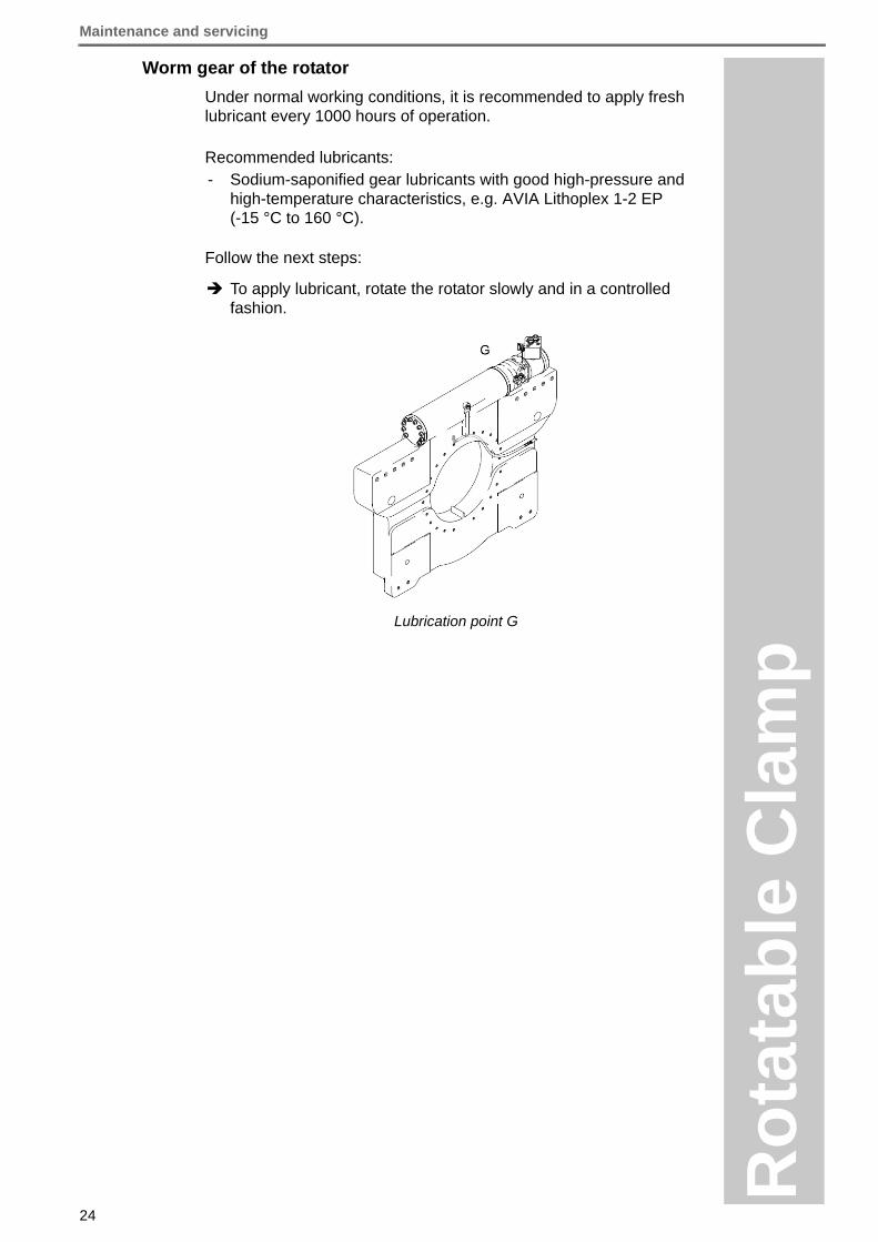
Under normal working conditions, it is recommended to apply fresh lubricant every 1000 hours of operation.
Recommended lubricants:- Sodium-saponified gear lubricants with good high-pressure and
high-temperature characteristics, e.g. AVIA Lithoplex 1-2 EP (-15 °C to 160 °C).
Follow the next steps:
To apply lubricant, rotate the rotator slowly and in a controlled fashion.
Lubrication point G
Maintenance and servicing
25
Ro
tata
ble
Cla
mp
500-
Ver
sGB
-031
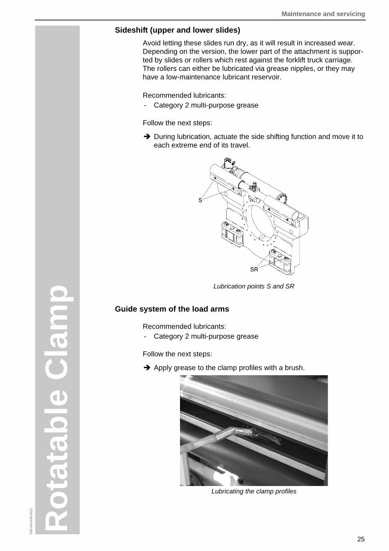
2Sideshift (upper and lower slides)
Avoid letting these slides run dry, as it will result in increased wear. Depending on the version, the lower part of the attachment is suppor-ted by slides or rollers which rest against the forklift truck carriage. The rollers can either be lubricated via grease nipples, or they may have a low-maintenance lubricant reservoir.
Recommended lubricants:- Category 2 multi-purpose grease
Follow the next steps:
During lubrication, actuate the side shifting function and move it to each extreme end of its travel.
Lubrication points S and SR
Guide system of the load arms
Recommended lubricants:- Category 2 multi-purpose grease
Follow the next steps:
Apply grease to the clamp profiles with a brush.
Lubricating the clamp profiles

Disposal
26
Ro
tata
ble
Cla
mp
Disposal
After the expiration of the assigned working period or working life has been reached, the attachment may be decommissioned and scrap-ped.
Disposal of the attachment
Follow the next steps:
1. Decommission the attachment (see chapter ).
2. Take appropriate measures to ensure that the attachment is kept from being used again.
3. Dismantle the attachment professionally.
4. Separate all individual parts and scrap them according to the materials used.
5. Dispose of all surplus fluids according to regulations.

Addendum
27
Ro
tata
ble
Cla
mp
500-
Ver
sGB
-031
2Addendum
Torque table for bolted fastenings
When tightening cylinder head and hexagon type bolts, the correct torque must be obtained by using a torque wrench.
The necessary torque requirements are classified by bolt sizes and strengths in the table below.
Old and used bolts must always be replaced by new ones.
Hydraulic circuits
Rotation function
Threads Strength category For Verbus Ripp 100
bolts8.8 10.9 12.9
M4 3.1 Nm 4.5 Nm 5.3 Nm ---
M5 6.1 Nm 8.9 Nm 10.4 Nm 10 Nm
M6 10.4 Nm 15.5 Nm 18 Nm 18 Nm
M8 25 Nm 37 Nm 43 Nm 37 Nm
M10 51 Nm 75 Nm 87 Nm 80 Nm
M12 87 Nm 130 Nm 150 Nm 120 Nm
M14 140 Nm 205 Nm 240 Nm 215 Nm
M16 215 Nm 310 Nm 370 Nm 310 Nm
M18 300 Nm 430 Nm 510 Nm ---
M20 430 Nm 620 Nm 720 Nm ---
M22 580 Nm 830 Nm 970 Nm ---
M24 740 Nm 1060 Nm 1240 Nm ---
M27 1100 Nm 1550 Nm 1850 Nm ---
M30 1500 Nm 2100 Nm 2500 Nm ---
Tightening Torque Values

Addendum
28
Ro
tata
ble
Cla
mp
Side shifting function (optional)
Load arm adjustment function