Embed Size (px)
Citation preview


.
Table of
Introduction . . . . . . . . . . . . . . . . . . . . . . . . . . . . . . . . . ...3Nomenclature . . . . . . . . . . . . . . . . . . . . . . . . . . . . . . ...3Receiving Inspection . . ...’..... . . . . . . . . . . . . . . . ...3
Unit Description . . . . . . . . . . . . . . . . . . . . . . . . . . . . . ...3Typical Component Locations., . . . . . . . . . . . . . . . . ...4Typical Unit Sections,...,.,., . . . . . . . . . . . . . . . . ...7Control Locations . . . . . . . . . . . . . . . . . . . . . . . . . . . ...8Control Panel Locations, . . . . . . ., . . . . . . . . . . . . . ...9Controls, Settings, and Functions . . . . . . . . . . . . . ...11
Mechanical installation . . . . . . . . . . . . . . . . . . . . . . . ...13Receiving Inspection . . . . . . . . . . . . . . . . . . . . . . . . ...13Unit Clearances . . . . . . . . . . . . . . . . . . . . . . . . . . . . ...13Roof Curb Assembly and Installation . . . . . . . . . . . ...15Post and Rail Mounting, . . . . . . . . . . . . . . . . . . . . ...16Rigging and Hand[ing . . . . . . . . . ., . . . . . . . . . . . . ...16Split Units . . . . . . . . . . . . . . . . . . . . . . . . . . . . . . . . ...17Reassembly of Split Units..,.. . . . . . . . . . . . . . . ...17Installing Ductwork, . . . . . . . . . . . . . . . . . . . . . . . . ...21Installing Duct Static Pressure Sensor Taps ., .,....21Installing Building Static Pressure Sensor Taps . . ...22Condensate Drain Connection ., . . . . . . . . . . . . . . ...23Field Refrigerant Piping and Charging of DX Coils ..24Unit Piping . . . . . . . . . . . . . . . . . . . . . . . . . . . . . . . . ...26Vestibule . . . . . . . . . . . . . . . . . . . . . . . . . . . . . . . . . ...29Damper Assemblies . . . . . . . . . ., . ., . . . . . . . . . . ...31Cabinet Weatherproofing . . . . . . . . . . . . . . . . . . . . ...34
Electrical installation, . . . . . . , . . . . . . . . . . . . . . . . ...35Field Power Wiring . . . . . . . . . . . , . . . . . . . . . . . . . ...35Field Control Wiring, ..,....., ., . . . . . . . . . . . . ...37
Preparing Unit for Operation. . . . . . . . . . . . . . . . . . ...37Release of Spring Mounts . . . . . . . . . . . . . . . . . . . ...37Adjustment of Supply Fan Thrust Restraints . . . . . ...38Adjustment of Spring Mounts,.. . . . . . . . . . . . . . . ...38Seismic Restraints . . . . . . . . . . . . . . . . . . . . . . . . . ...38
Sequences of Operation . . . . . . . . . . . . . . . . . . . . . ...39Power-up . . . . . . . . . . . . . . . . . . . . . . . . . . . . . . . . . ...39Fan Operation . . . . . . . . . . . . . . . . . . . . . . . . . . . . . ...39Economizer Operation . . . . . . . . ., . . . . . . . . . . . . ...40Heating Operation . . . . . . . . . . . . . . . . . . . . . . . . . . ...40
Wiring Diagrams . . . . . . . . . . . ., . . . . . . . . . . . . . . . ...41Legend, . . . . . . . . . . . . . . . . . . . . ., . . . . . . . . . . . . ...41Typical Power Circuit With Power Pack Only. ,. . . ...42
Typical Compressor Staging Outputs. . . . . . . . . . . ...42Typical Power Circuits With Controls . . . . . . . . . . . ...42Typical Main Control Circuit (VAV Units) . . . . . . . . ...43Typical Main Control Circuit (CAV-ZTC Units) ,. . . ...44Typical Main Control Circuit (CAV-DTC Units) . . . . ...45Typical Actuator Control Circuit . . . . . . . . . . . . . . . ...46TypicalSupply/Return Fan Control Circuit, . . . . . . ...46Typical Gas Furnace Control Circuit
(Modulating Burner, Mixed Air Intake) . . . . . . . . ...47Typical Electric Heat Control Circuit (Multistage) . ...48
Unit Options . . . . . . . . . . . . . . . . . . . . . . . . . . . . . . . . ...49Enthalpy Control . . . . . . . . . . . . . . . . . . . . . . . . . . . ...49Part Winding Start. , .,......, . . . . . . . . . . . . . . . ...49Ground Fault Protection . . . . . . . . . . . . . . . . . . . . . ...49Phase Voltage Monitor . . . . . . . . . . . . . . . . . . . . . . ...49Optional Remote Monitoring and Control Panel . . ...50Remote Monitor Panel . . . . . . . . . . . . . . . . . . . . . . ...50External Time Clock, . . . . . . . . . . . . . . . . . . . . . . . ...50Smoke Detectors . . . . . . . . . . . . . . . . . . . . . . . . . . . ...50Freeze Protection . . . . . . . . . . . . . . . . . . . . . . . . . . ...50Duct High Pressure Limit . . . . . . . . . . . . . . . . . . . . ...51Variable inlet Vanes . . . . . . . . . . . . . . . . . . . . . . . . ...51ConvenienceReceptacle/SectionLights . . . . . . . . ...55
Check, Test, and Start Procedures . . . . . . . . . . . . . ...55Before Start-up . . . . . . . . . . . . . . . . . . . . . . . . . . . . ...55Power-up . . . . . . . . . . . . . . . . . . . . . . . . . . . . . . . . . ...56Fan Start-up . . . . . . . . . . . . . . . . . . . . . . . . . . . . . . . ...56Economizer Start-up . . . . . . . . . . . . . . . . . . . . . . . . ...56Heating System Start-up. . . . . . . . . . . . . . . . . . . . . ...57Cooling System Start-up.....,.. . . . . . . . . . . . . . ...57Adjusting MicroTech Controls&Servicing . . . . . . . ...57Air Balancing . . . . . . . . . . . . . . . . . . . . . . . . . . . . . . ...58Final Control Settings . . . . . . . . . . . . . . . . . . . . . . . ...60
Maintenance . . . . . . . . . . . . . . . . . . . . . . . . . . . . . . . . ...65Preventive Maintenance . . . . . . . . . . . . . . . . . . . . . ...65Unit Storage . . . . . . . . . . . . . . . . . . . . . . . . . . . . . . ...65Gas Furnace . . . . . . . . . . . . . . . . . . . . . . . . . . . . . . ...65Bearing Lubrication, .,....... . . . . . . . . . . . . . . . ...65Setscrews . . . . . . . . . . . . . . . . . . . . . . . . . . . . . . . . ...66Airfoil Supply Fan Wheel-to-Funnel Alignment . . . ...66Winterizing Water Coils. ..,.... . . . . . . . . . . . . . . ...67
Service and Warranty Procedure . . . . . . . . . . . . . . ...67In-Warranty Return Material Procedure . . . . . . . . . ...67Replacement Parts . . . . . . . . . . . . . . . . . . . . . . . . . ...67
Product Warranty . . . . . . . . . . . . . . . . . . . . . . . . . . . ...68
Installation and maintenance are to be performed only by qualified personnel who are familiarwith local codesand regulations, and experienced withthistypeof equipment. Caution: Sharpedgesand coilsurfacesare apotentialinjury hazard. Avoid contact with them.
Page2/lM487

Introduction
This manual provides general information about the “C” vin-tage McQuay RoofPak applied rooftop unit, model RAH. In ad-
I dition to an overall description of the unit, it includes mechani-cal and electrical installation procedures, commissioning pro-cedures, sequence of operation information, and maintenanceinstructions. For further information on the optional forced draftgas fired furnace, refer to Bulletin No. IM 484.
The MicroTech Applied Rooftop Unit Controller is availableon “C” vintage roof mounted air handlers. For a detailed de-scription of the MicroTech components, input/output configura-tions, field wiring options and requirements, and service pro-cedures, refer to Bulletin No. IM 483, “MicroTech Applied Roof-
top Unit Controller.” For a description of operation and informa-tion on using and programming the MicroTech unit controller,refer to the appropriate operation manual (see Table 1).
Table 1. Applied Rooftop Unit Operation Manual Literature
Rooftop Unit Operation ManualControl Configuration Bulletin Number
Variable Air Volume (VAV) OM 108
Constant Air Volume, ZoneTemperature Control (CAV-ZTC)
OM 109
Constant Air Volume, DischargeTemperature Control (CAV-DTC)
OM 110
Nomenclature
R AH –047CSE
~~~~~e= [-
Roof Pak
047 (Small Cabinet)077 (Large Cabinet)
1
Heat MediumA = Natural Gas
E = Electric
S . SteamW = Hot WaterY = None
Cooling Coil SizeS = Standard (Low Airflow)L = Large (High Airflow)Y = None
~ Designvintage
ReceivingWhen the equipment is received, all items should be careful-ly checked against the bill of lading to be sure all crates andcartons have been received. All units should be carefully in-spected for damages when received. If any damage is notic-ed, the carrier should make the proper notation on the deliveryreceipt acknowledging the damage. If the unit has gottendirty during shipment (winter road chemicals are of partic-
Inspectionular concern), it should be cleaned off when received. Thecarrier should also fill out a Carrier Inspection Report. TheMcQuay International Traffic Department should then be con-tacted at (612) 553-5330.
The unit nameplate should be checked to make sure thevoltage agrees with the power supply available.
IM 487 I Page 3

Typical Component Locations
Figures 1 through 3 show typical RAH units with the location of the major components and also lists some major dimensions.These figures are for reference only. See the certified submittals for actual specific dimensions.
Figure 1. Blow-Through Configuration (Unit Size 077C Shown)
Plan View
Bottom Return ~r Openin9 -
,,(15;mm~
L,!
(15;mm) ~
r10“
Return Air Dampers
f
optional Outside &
(254mm)
r
Optional Exhaust Dampers
rI
I,-_l~l,,l,,I-r’ L
I--A--I
11—— —.
-_——
‘I11/# MPTcondensateDrain Connection
,,
(2J’mm)
, Bottom DischargeOpening
/’
/’/
j
\ ‘rOptional Return Air Fan
\
Control Entrances _ L powerEntrances7/*1’ Diameter Knockout 3“ Diameter Knockout
(2 Places)
Elevation
supply Air Fan
r
Cooling Coil
T ‘i-Discharge Plenum
+ llL-==L=-1~+,’
II,,./g. ~.—-----., II
,,.,,+[<.’.,~,.,
-.<.. .,
.,:/G
/i’
Main Control Panel(Optional)
/ / L~i,tese.tiofl \
/
LOptional OutsideLouvers (Both Sides)
~ Optional Back Return AirOpening 93.5” (2375mm) Long
Unit Size 047C Medium Cabinet
Heat Section (Natural Gas, Steam,Hot Water, Electric)
Unit Size 077C Large Cabinet
DescriptionDimensions in Inches (mm)
“A” “B” “c. “D,*
41.8With Flat Cooling Coil (1$5) (::5) (2%4) (1062)
Wth Staggered or 41.6
No Cooling Coil (1:5) (1%8) (2:4) (1062)
page 4 I IM 487

Figure 2. Draw-Through Configuration with SWSI Supply Fan (Unit Size 077C Shown)
Bottom Return Air Opening
1
Plan View
rOptional
/
Outside & Return Air Dampers r Bottom 13scharge Opening
1Ilz” MPT Condensate
I
10’”
r
Drain Connection (254mm)
~Bfl ‘~(15.%m)
Heating/Cooling Coil
Elevation
\
Optional Exhaust Dampers
\
l-]c
1[TD
I
rOptional Return Air Fan
-+-t
~——~.11, 01II . . ~.o.
Control Entrances _718” Diameter Knockout \ Power Entrances
3“ Diameter Knockout
Water
rSupply Air Fan
Lrnit siZe 047C Medium Cabinet
~
(2 Places)
7“’.——_———.——_.—————————
\ I.
Optional Back Return Air /Opening 93.5” (2375 mm) Long L L ~lter section
Optional Outside AirLouvers (Both Sides)
L-Main Control Panel (Optional)
Unit Size 077’CLarge Cabinet
~
IM 487 I Page 5

vq-
5
>
L
——— ————— .
Jai!~_____-–––-––__—.—.—.—.—.—.—.—*-------------L------------, - !
w;---------– –,- Z--114+--- ___7______4,,4,,
L______7L__-_--Jlo
F--–-.+-––-----1!
:/’ I-––7----r–_–T____
---1--__l–---:____~.–-– -—————-—-
q,-—-—-—~_-–- —_—-—-———-
+
-—-—J I1 !-—--
~---- —----I
I I
7’ I
IL ——————————. =x
—---—- -—- -—--II 1, 11
l_–__ll____ll____ll____
I/
Tal
I —

Typical Unit Sections
The individual sections that make up a rooftop can vary from unit to unit. All available sections are shown below in Figure 4.
Figure 4a. Typical Unit Sections (Draw-Through and Blow-Through with D WDI Supply Fan)
Note: Views shown for 047C family. Not to scale
RET. &lR
0~/HOOD‘
aPLENUM
u30L DA
IIECONO
sECONO/R&
RMlXlNCBOX
n
,:.:: !0,,
OPTEV&PCOOL
[:
8LANK
n
J
S6 FfiN
[1
❑,----,-,
?- . ...,!. /---
Figure 4b. ~pical Unit Sections (Draw-Through with SWSI Supply Fan)
Note: Views shown for 047C family. Not to scale.
FILTER-.
TA/30
i
:>
:.,:
65/95
[
,!“$;,,.,,,
STAGG
I
pl
OL~NK
[OLONK
u/
OPTEVR?COOL
.
1
BLANK
u
.
h-wHEbT
PLEN--
II
---
IM 487 I Page 7
—

Control LocationsAll controls on the RAH are optional. If controls are ordered,
legend which is included in the ‘rWiring Diagrams” section
Figure 5 shows the locations of the various control com- of this manual. Figure 5 shows blow-through heat and blow-
ponents mounted throughout the unit. See “Control Panel through coil sections. These sections are also available in the
Locations” for the locations of control components mounteddraw-through position. All controls mounted in the blow-
in control panels. Additional information is included in Table through section would be located in the same position within
2, “Controls, Settings, and Functions,” and the wiring diagram the draw-through section.
Figure 5. Control Locations
Oischarge Plenum Section
Blow-through coil SeCtiOn
Blow-through Heat Section SD1 (Optional)
SUpply Fan Section
Filter SeCtiOn7
~ SAT
Return Air Economizer _ Fka
C9, 10 (Optional)
ACT1 (Optional)
C19, 20(Optiona
RAT
ACT2
\\l v-’\ \ \ \~cT~ (Optional)
VM1 (Optional)
Optional)
-/ 1 [[L \oA,LTI 1 (OptiOnal) ACT6 (Optional)
RAE (Optional)
SII, REC1l SD2 (Optional)(Optional)
See page 41 for designationldescription.
Page 8 / IM 487

Control Panel LocationsThe unit control panels and their locations are shown in the following figures. These figures show a typical unit configuration.Specific unit configurations may differ slightly from these figures depending on the particular unit options.
Main Control PanelPower Pack Only
..-” ”— ”---- . . ./.”. .
..\ 1’~,.,(bii ‘“\,~~ ‘ “.
;\ /’‘>\ /’,,,.,. ,/
.. . ./.. . . . . . . . ..- . . . .
PANEL
Component Locations~.. -.. —----- . ..,. ” ., .. .
,/’‘\./
‘.lm,.
/’ -- \fji ~;,% \
,., . . . . . I\ ,! ::;
,,+-.!:-:--: @) i\ RE61WRIWM /’~\ /’,/’” .. ,.
x. /.,. , ... .. ..-. ... ... ..-
I
i
I
I
1,
\\\
rB5 I
I
I
rBl 0 !
I
;
1 ~“..b /\\ ;\ ,./..\ ,./
See Page 41 for designationldescription.----
IM 487 I Page 9

Main Control Panel Component Locations
‘L---0===[IKE”P.D/.——.
❑—
Control
See Page41 fordesignation/description.
Box
..-
TB13
---
..-
TB12
---
I r
. .
—
uM2@
I uT1
c
I
Component Locations
. .II
Elmml!qIII
\- “,
‘.””’”OS: ‘N,\\ \\\\ pf$’ ,,.1, ‘-’\ \ ‘,::’-,\ ,.,. \z.,\ . ~,
.,. - ,.’ ;’. ,\ ,.-,[:, .‘,,(; , .
.
/“”
Page 10 / IM 487

Controls, Settings, and FunctionsTable 2 presents a listing of all the unit control devices. Included in the table are the device symbol, a description of the device, its function, any reset information, its location,any device setting, any setting ranges, differentials, and the device part number.
Table 2. Controls, Settings, and Functions
SymbolADI
DHL
FS1
MAT
MCB1
OAE
OAT
OBA, B, & C
PC 5&6
PC?
RAE
RAT
SAT
SB1 & 2
SD1
SD2
SPS1
SPS2
z*co+ SPS5\-o&CD
Description Function Reset I
ADI Board Collects and conditions analog and digital inputs. NIA
Duct high limit Prevents excessive VAV duct pressures; shuts off fan. Auto
Freezestat Shuts off fans, opens heating valve and closes out- Auto Idoor damper if low air temperature at coil is detected.
Mixed air temperature Senses mixed air temperature; sends signal to MicroTech NIAsensor controller,
Microprocessor Control Processes input information and controls output relays as NIABoard appropriate.
Enthalpy control Returns outside air dampers to minimum position when Auto(electromechanical) enthalpy is too high.
Enthalpy control Returns outside air dampers to minimum position when Auto(electronic) outside air enthalpy is higher than return air enthalpy
(used with RAE).
Outside air temperature Senses outside air temperature; sends signal to NIAsensor MicroTech controller.
Output Boards A, B, or C Holds MicroTech solid-state output relays. NIA
Filter switch Turns on clogged filter light on status panel. Auto
Differential pressure switch Senses supply fan pressure to prove airflow. Auto
Return air enthalpy sensor Used to compare return air enthalpy to outside air en- NIAthalpy (used with OAE).
Return air temperature Senses return air temperature; sends signal to MicroTech NIAsensor controller.
Supply air temperature Senses discharge air temperature; sends signal to NIAsensor MicroTech controller.
Staging Board 1 or 2 Provides stepped cooling or heating control. NIA
Smoke detector, supply air Initiates unit shutdown if smoke is detected. Manual
Smoke detector, return air Initiates unit shutdown if smoke is detected. Manual
Duct static pressure sensor Converts static pressure signals to voltage signals and NIA#1 sends them to MicroTech controller.
Location Setting Range
Main control panel NIA NIA
Main control panel 3.5” W.C.(872 Pa) 0.05-5.0” W.c,(13-1245 Pa)
Heating section 38° F or as required 35-450 F(3”C) (2-7oC)
Inlet of supply fan NIA 3K ohms at 77° F(25”C)
Main control box I N/A I NIA
Economizer section “B” or as required A—O(20 c)Humid.: 50/o fixed
Economizer section Fully CW past “D” A—D(when used withRAE)
Under condenser section N/A 3K ohms at 77° FOutside wall of discharge (25”C)plenum section.
Main control box NIA NIA
I I
Return air section I NIA I 3K ohms at 770FI (25”C)
Discharge air section I NIA 13K ohms at 7T” F(25oC)
Main control box NIA NIA
Discharge air section NIA NIA
Return air section I NIA I NIA
Main control box ] N/A I o to 5“ WC.(0-1245 Pa)1-8 VDC out
Main control box NIA o to 5 ‘f WC.
Dlfferentisl Part #UIA 858160B-05
05” W.C. (13 Pa), 654938B-01ixed
+
+
+NIA 665422B-01
(16 position)665422B-02( 8 position)665422B-03( 4 position)
0.05” WC. 654936B-01
Duct static pressure sensor COMKMS static pressure signals to voltage signals and NIA#2 sends them to MicroTech controller.
Building static pressure Converts static pressure signals to voltage signals and NIAsensor sends them to MicroTech controller.
Dirty filter pressure sensor Senses pressure drop across first filter bank and sends NIAsignal to MicroTech controller,
Contined on next page
N/A I 6582!35B-05
I
NIA 658295B-01
I
N[A 495450B-05
I
1
NIA 495450B-05
I

CDTable 2. Controls, Settings, and Functions (continued)
NSymbol Description Function Reset Location Setting Range Differential Part #
z SPS6 Dirty filter pressure sensor Senses pressure can drop across final filter bank and NIA Final filter section NIA o to 5“ W.c. N/A 495450B-05
.Psends signal to MicroTech controller. (0-1245 Pa)
co 1-6 VDC out4 S1 System switch Shuts off entire control circuit (except crankcase heaters) NIA Main control box N/A NIA NIA 012550B-00
TD9 & 19 Part winding start liner (fans) Reduces inrush amp draw on start-up. Auto Main control box 1 see, fixed N/A N/A 262101D-O1
ZNT1, 2, & 3 Space temperature sensors Senses space temperature; sends signal to NIA In building space N/A 3K ohms at 71° F NIAMicroTech controller.
See IM 483(25”C)
GAS HEATING CONTROLSAS Blower air switch Proves presence of combustion air. N/A Gas furnace control 0.4” WC., fixed N/A NIA 330036B-00
section (100 Pa)
FD Flame rod Senses pilot flame. N/A Gas burner assembly N/A NIA NIA 365577A-00
Fan control Closes to energize fan when heat exchanger is warm. Auto Gas heating section Closes at 125° F 65-220” F 25° F, adjustable(52”C) (18-104°C) (14”C)
FLC Opens at 100” F 50-205° F 340821B-00(36oC) (10-96oC)
High limit control Opens furnace control circuit on temperature rise. Auto Gas heating section Opens at 200” F 100-2500 F 250 F, fixed(93”C) (38-121”C) (14”C)
FSG Flame safeguard Proves pilot flame and controls main gas valve. Manual Gas furnace control NIA NIA N/A See IM 484section
GV1 Pilot gas valve Opens to allow flow of gas to pilot burner. Normally Gas heating section NIA N/A N/A 344864B-00closed
GV2, 3 Main gas valves Opens to allow flow of gas to main burner. Normally Gas heating section N/A NIA N/A See IM 484closed
HL22 Filter high limit control Opens furnace control circuit on temperature rise. Manual Supply air section Opens at 125° F N/A 250 F, fixed 479388B-01(52°C) (14”C)
HL23 Final filter high limit control Opens furnace control circuit on temperature rise. Manual Final filter section Opens at 1650F N/A 25” F, fixed 479388 B-046(74”C) (14”C)
HPR High pressure regulator Regulates pressure to main regulator. N/A In gas line before MPR As specified 10.0to 13.0” W.c. NIA See parts catalog(2491-3238 Pa)
HP5 High gas pressure switch Shuts off burner if pressure goes above setpoint. Manual Gas heating section 6“ W.C, 5-35 ‘c W.c. 1-3” WC, See parts catalog(1993 Pa) (1245-8718 Pa) (249-747 Pa)
LP5 Low gas pressure switch Shuts off burner if pressure goes below setpoint. Auto Gas heating section 4“ W.c. 3-21 “ W.C. 1-3“ W.c. See parts catalog(996 Pa) (747-5231 Pa) (249-747 Pa)
ELECTRIC HEATING CONTROLSHL1 — 8 Secondary heater limit Breaks line voltage to heaters if temperatures are too high. Manual Electric heat section Cut out=210° F N/A NIAHL1 — 18 control
654962B-01(99”C)
HL31-34 & Primary heater limit control Breaks control voltage to electric heat contactor if heater Auto Electric heat section Cut out=175° F NIA 300 F, fixed 658245B-01
41-44 temperatures are too high. (79”C) (16”C)Cut in=145° F(63oC)
HS1 Switch (toggle), Shuts off electric heat control circuit manually. N/A Main control box NIA NIA NIA 237803D-01
electric heat
HS3 Switch (momentary), Shuts off electric heat control circuit if heater dead front N/A Electric heat section NIA NIA NIA 336963A-00electric heat is removed.

Mechanical Installation
The installation of this equipment shall be in accordance withthe regulations of authorities having jurisdiction and all ap-plicable codes. It is the responsibility of the installer to deter-mine and follow the applicable codes. Sharp edges are inherent to sheet metal parts, screws,
clips, and similar items. Can cause personal injury. IThis equipment is to be installed and operated only by an ex-perienced installation company and fully trained personnel. IExercise caution when servicing equipment. I
Unit ClearancesService Clearance
Allow service clearance approximatelv as indicated in Figure unit that provide access to most controls and serviceable6 below. Also, it is recommended that a roof walkway be pro- components.vialed to the rooftop unit and along at least the two sides of the
Figure 6a. RAH Unit With Housed DWDI Supply Fan
r ,!
(18~mm)
Location
Figure 6b. RAH Unit With SWSI Plenum Supply Fan
I r
T
1 1 I I I I I
F:E—NohLu- 8 G 0
mg
?
/ Y//////////M//////////&
-WI(18~m),,
(24$mm)r V.. .
v//4m—_’ / I 1~rluwl
Walkwayi
1 v I
I I
—24”[635mm)
Note:Sections with heating and/or cooling coils or DWDI supply
fan must have 96” service clearance on control box side.
Legend:A= Return Air SectionB = Filter SectionC =Combination Coil SectionD = Heat SectionE= Supply Fan SectionF= Discharge Plenum Section
TO RoofAccess P ‘1
Location Varies With Unit ArrangementRefer to Certified Drawing & Note
IM 487 I Page 13

Ventilation Clearance
Following are minimum ventilation clearance recommenda-tions. The system designer must consider each applicationand assure adequate ventilation. If this is not done, the unitwill not perform properly.
Unit(s) surrounded by a screen or fence:1. The bottom of the screen or fence should be at least one
foot above the roof surface.
2. The distance between the unit and the screen or fenceshould be as described in “Service Clearance” above.
3. The distance between any two units within the screen orfence should be at least 120 inches (3048mm).
Unit(s) surrounded by solid walls:1, If there are walls on one or two adjacent sides of the unit,
the walls may be any height, If there are walls on morethan two adjacent sides of the unit, the walls should notbe higher than the unit.
2. The distance between the unit and the wall should be atleast 96 inches (2438 mm) on all sides of the unit.
3. The distance between any two units within the walls shouldbe at least 120 inches (3048mm).
Do not locate outside air intakes near exhaust vents or othersources of contaminated air.
If the unit is installed where windy conditions are common,wind screens should be installed around the unit, maintain-ing the clearances specified above. This is particularly im-portant to prevent blowing snow from entering outside airintakes.
Overhead Clearance
1. Unit(s) surrounded by screens or solid walls shall have nooverhead obstructions over any part of the unit.
2. The following restrictions shall be observed for overheadobstructions above the air handler section (see Figure 7).
a. There shall be no overhead obstructions above the fur-nace flue, or within 9 inches (229mm) of the sides ofthe flue box.
b. Overhead obstructions shall be no less than 2 inches(51mm) above the top of the unit.
c. There shall be no overhead obstructions in the areasabove the outside air and exhaust dampers that are far-ther than 24 inches (610mm) from the side of the unit.
Figure z Overhead Clearance
9“ (229mm) Minimum To FlueBox Typical All Sides
2“ (51mm) MinimumTop of UnitTo OverheadObstruction
Page 14 / IM 487
24” Max.(61Omm)

Roof Curb Assembly and Installation
The roof curb and unit must be located on a portion of the flanges seals against the unit when it is set on the curb. Itroof that can support the weight of the unit. The unit must is not recommended that these flanges support the totalbe supported to prevent bending or twisting of the machine. weight of the ductwork. Refer to the “installing Ductwork” sec-
If building construction could allow the transmission of tion for details on duct connections.sound and vibration into the occupied space, it is recom- Assembly of a typical RAH roof curb is shown in Figuresmended that the unit be located over a noncritical area. It is 8a and 8b. Refer to instruction drawing provided with roof curb.the responsibility of the system designer to make adequate Parts A through H are common to all units having bottomprovisions for noise and vibration in the occupied space. return openings. Depending on the unit length, Parts L and
Integral supply and return air duct flanges are provided with M maybe included with the roof curb kit to create the correctthe RAH roof curb, allowing connection of ductwork to the curb overall curb Iength.before the unit is set. The gasketed top surface of the duct
.
Figure 8a. RAH Roof Curb Assembly Instructions,,.
(Z!i;;m>+ ~jo~m)Detail “A’
Using remaining side supports in this
area, align lengths on opposite sides of
assembly and install a cross support “D”
at each splice.A
EOUAL:W[GT “
SUPPORTS
RAH Unit3imensions in. (mm)
“x” “y,.
047C (::5) (;: )
077C With Flat Cooling Coil and/or4411 SWSI Plenum Supply Fan (1:5) (::5)
077C With Staggered or No Cooling Coil,and/or 49fI SWSI Plenum Supply Fan (1%5) (1%8)
Unit Base
Curb Gasketing2 x 4 Nailer StripGalvanized CurbCant Strip (Not Furnished)Roofing Material (Not Furnished)Rigid Insulation (Not Furnished)C&nterflashing (Not Furnished) ~ ~A,N “NIT CURBFlashing (Not Furnished)
Assembly Instructions:1.2.
3.4.5.
6.
7.8.9.
Set c;rbing parts A thru H per dimensions shown over roof opening or on a level surface. Note location of return and SU!JDIVair oReninWIf applicable, set other curbing parts (D, L, M, etc.) in place making sure that the orientation agrees with the assembly instrfictions. Ch[ckalignment of all mating bolt holes. See Detail “A’.Bolt curbing parts together using fasteners provided. Tighten all bolts finger tight.Square entire curbing assembly and securely tighten all bolts.Position curb assembly over roof openings. Curb must be level from side to side and over its length. Check that top surface of the curbis flat with no bowing or sagging.Weld curbing in place. Caulk aH seams watertight. Remove backing from 0.25 thick x 1.50 wide gasketing and apply to surfaces shownby crosshatching.Flash curbing into roof as shown in Detail “B”.Parts E and F are not required on units with no return shaft within the curb perimeter.Parts G and H are not required on units with no supply shaft within curb perimeter.
IM 487 I Page 15
I

Post and Rail Mounting
When mounting by Post and rail, the structural support should Figure 9. Post and Rail Mountingbe run the full length of the unit to prevent any deflection ofthe cabinet. The structural member should be located at the
4
base of the unit as shown in Figure 9 assuring the shaded,,
(12~m’m)-
‘2’;;”)-area is well supported by the structural member. l’rl T
To assure proper system operation, it is important that theunit is mounted level.
The post and rail setup should be done so that the unit is levelfrom side to side and over its entire length.
If resilient material is placed between the unit and the rail,insert a heavy steel plate between the unit and the resilientmaterial to distribute the load. Cabinet penetrations (electrical, !l_l!!l_
piping, etc.) should be sealed in a professional manner to pro- ------- ---- -------
tect against moisture and weather. “ Maximum recommended width for structural member is 5“(127mm) to allow for adequate space for duct connections andelectrical entry
Rigging and Handling
Lifting brackets with 2 inch (51mm) diameter holes are pro- with adequate support.vialed on the sides of the unit. Figure 11 shows an example of the rigging instruction label
Use spreader bars, 101 to 105 inches (2565 to 2667mm) shipped with each unit.wide, to ‘prevent damage to the unit cabinet. Avoid twistingor uneven lifting of the unit. The cable length from the bracketto the hook should always be longer than the distance bet-ween the outer lifting points.
If the unit must be stored at the construction site for an in- All lifting points must be used. Adjustment maybe required
termediate period, set the unit in a reasonably level positionfor the middle cable in a six-cable arrangement.
Figure 10. Rigging and Handling Instruction Label
Rigging and Handling InstructionsUnit has either four or six lifting points (six-point shown below),
Caution: All lifting points must be used.Note: Rigging cables must beat least as long as distance “A”.
SpreaRequi
/v Caution: Lifting points may notbe symmetrical to center of grav-ity of unit. Ballast or unequalcable lengths may be required.
Lift Only As Indicated
Page 16 / IM 487

ILifting Points and Cable LengthsTo determine the required lifting cable lengths and whetherfour- or six-point lifting is required, use Table 3 and Figure 11.
Referring to Figure 11, note that Dimension A is the dis-tance between the outer lifting points. The four outer riggingcables must be equal to or longer than Dimension A. Dimen-sion B shows the minimum distance between the outer andthe inner lifting points for six-point lifting. This can be usedto roughly determine the required length of the middle cablesfor six-point lifting. Dimension A can be determined by sub-tracting Dimension X from Dimension Z (i.e., A = Z - X).
Where:Z = Total unit length in inches (refer to certified drawings for
this dimension).
X = Refer to Table 3 for this dimension
If A < 288 inches (7315mm), 4-point lifting is sufficient.If A > 288 inches (7315mm), 6-point lifting is required.
Table 3. “X” Dimension (See Figure 11)
Type of Economizer Section 047C 077C100%OA o 0Plenum 48” (1219 mm) 72” (1829mm)
O — 2.00/o OA 48” (1219 mm) 72” (1829 mm)
O — 100°/0 Economizer 72” (1829mm) 96” (2438 mm)
O — 100°10 EconomizerWith Return Fan
72” (1829 mm) 96” (2438 mm)
Figure 11. Unit Type RAH
4 Lifting Points I 6 Lifting Points
Split Units
Althouqh RAH units typically ship from the factory in one limitation prevented a packaged RAH from being ordered.piece, units with blow-through sections maybe factory split atthe supply fan bulkhead, to be recoupled on the roof. Thisconfiguration would be ordered if shipping length or weight
Reassembly
Field reassembly of an RAH unit that has shipped split at thefan takes place in two places:1. Setting the sections and mechanically recoupling the
cabinet.2. Reconnecting power and control wiring if optional power
pack and/or controls are used.
Setting the Sectionsand Cabinet ReassemblyThe steps required to set the unit and reassemble the cabinetare shown in Figures 12a through 12c. The following itemsshould be noted:1. Top cap and plywood covers must be removed before the
sections are set together, but the steel retainer clips mustbe left in place to secure the bulkhead. Refer to Step #1in Figure 12a.
A single nameplate is attached to the air handler sectionand power is fed to both sections through the optional main
control box as it would be in a packaged RAH unit.
of Split Units
2. Both sections must be lowered into place carefully to makesure that the roof curb engages the recesses in the unitbase.
3. All seams at the split must be caulked watertight afterrecoupling the sections, as shown in Step #3 of Figure 12b.
Reconnecting Power and Control Wiring(Units With Optional Factory Wiring)The discharge sections contain power and control harnesseswhich have their excess length in the blank or heat sectionthat is normally immediately downstream of the fan. Oncethe sections are physically reconnected, the ends of thepower harness are fed back through the unit base into thejunction box, per the unit’s electrical schematics.
IM 487 I Page 17

I Care must be exercised to connect the proper power blockand maintain proper phasing. I
When reconnection of the power wires is complete, the in-ner raceway cover in the blank or heat section must bereinstalled. Step #4 of Figure 12c shows a typical installationof the raceway cover.
Control harnesses may be run by removing the externalraceway covers on either side of the unit split. The excessharness length may be removed from the external racewayon the discharge side of the split, routed along the racewaythrough the bushed hole in the fan section, and into the junc-tion box where control wiring terminal blocks are provided forreconnection. All electrical connections should be made perthe unit’s electrical schematics. Re-install the external racewaycovers after routing of the control wires is complete.
Figure 12a. Reassembly of Split Unit
Step 1Prepare units for reassembly as shown.
REMOVE PLYWOOD AND RETAINING
k
ANGLES FROM UNIT AND DISCARD
f
OISCHARGE END OF UNIT
L REMOVE SCREWS ON FAN PANEL, BUTLEAVE RETAINER CLIPS IN PLACE;SAVE SCREWS FOR STEP 3
Step 2Set fan end of unit and discharge end of unit in place.
Page 18 I IM 487

r
Figure 12b. Reassembly of Split Unit
Step 3Caulk and install parts as shown.
\CAULK VERTICALSEAM )
fSPLICE COVER PROVIDED
‘\“%
[ INSTAL #loSCREWS PROVIDED
/
NUT CLIP-ON PROVIDED
IM 487 / Page 19

Figure 12c. Reassembly of Split Unit
Note: The fan diffuser is used in a
Step 4 blank heat section or in a steam andhot water heat section only.
A
~ INNER RACEWAY COVER ISTO BE INSTALLED AFTERWIRES ARE ROUTED(NOTE: SEE STEP 5)
Step 5Make electrical connections.
Page 20 I IM 487

Installing
On bottom-supply/bottom-return units, the installing contrac-tor should make an airtight connection by attaching fieldfabricated duct collars to the bottom surface of either the roofcurb’s duct flange or the unit’s duct opening if a McQuay roofcurb is not used. Do not support the total weight of the duct-work from the unit or these duct flanges. Refer to Figure 13.
Units with optional back return, side discharge, or enddischarge all have duct collars provided. The discharge ductcollars on a side discharge unit are exposed by removing theplenum section access door and the door gasketing.
Flexible connections should be used between the unit andductwork to avoid transmission of vibration from the unit tothe structure.
Ductwork should be designed per ASH RAE and SMACNArecommendations to minimize losses and sound transmission.Where return air ducts are not required, it is recommended
Figure 13. Installing Ductwork
UNIT DUCTOPENING
\ll
Ductwork
that a sound absorbing T or L section be connected tO theunit return to reduce noise transmission to the occupiedspace.
Ductwork exposed to outdoor conditions must be built inaccordance with ASH RAE and SMACNA recommendationsand local building codes.
On units with side discharge and a main control panel, ac-cess to plenum mounted components becomes difficultonce ductwork is installed.
I Installer must provide access in the ductwork for plenummounted controls. I
/
UNIT BASE
T‘9.76”
(248mm)
I
CONNECTOR fi’Ii!,$ \
~ ROOF CURB
Installing
.DUCT FLANGEIN ROOF CURB
Duct Static Pressure Sensor Taps
For all VAV units, duct static pressure taps must be field in-stalled and connected to the pressure sensors in the unit. Sen-sor SPSI is standard; additional sensor SPS2 is optional.These sensors are located at the bottom of the main controlpanel next to terminal block TB2 (see “Control Panel Loca-tions” in the “Unit Description” section of this manual).
The duct static pressure sensing tap must be carefullylocated and installed. Improper location or installation of thesensing tap will cause unsatisfactory operation of the entirevariable air volume system. Following are pressure tap loca-tion and installation recommendations. The installation mustcomply with local code requirements.
Fragile sensor fittings. May damage pressure sensor.
If tubing must be removed from a pressure sensor fitting, usecare. Do not wrench the tubing back and forth to remove orthe fitting may break.
1. Install a tee fitting with a leak-tight removable cap in eachtube near the sensor. This will facilitate connecting amanometer or pressure gauge if testing is required.
IM 487 / Page 21

2.
3.
4.
5.
6.
Use different colored tubing for the duct pressure (Hi) andreference pressure (LO) taps, or tag the tubes.
Locate the duct pressure (Hi) tap near the end of a longduct to ensure that all terminal box take-offs along the runwill have adequate static pressure.
Locate the duct tap in a nonturbulent flow area of the duct.Keep it several duct diameters away from take-off points,bends, neckdowns, attenuators, vanes, or other irregulari-ties.
Use a static pressure tip (Dwyer A302 or equivalent) or thebare end of the plastic tubing for the duct tap. (If the ductis lined inside, use a static pressure tip device.)
Install the duct tap so that it senses only static pressure
Figure 14. Duct Static Pressure Tap Installation
TO SENSOR
TO SENSOR“LO” INPUT
RUBBERROMMET
TUBE CLA
PRESSUTUBING
TUBING EXTENDS ~THRU APPROX, 1~”
7.
8.
(not velocity pressure). If an L-shaped pressure tip deviceis used, the point must face the airstream. If a bare tubeend is used, it must be smooth, square (not cut at anangle), and perpendicular to the airstream (see Figure 14).
Locate the reference pressure (LO) tap somewhere nearthe duct pressure tap within the building (see Figure 14).If the reference tap is not connected to the sensor, un-satisfactory operation will result.
Route the tubes between the curb and the supply duct,and feed them into the unit through the knockout in thebottom of the control panel (see Figure 15). Connect thetubes to the appropriate 1/4 inch fittings on the sensors.Assure that the sensors do not support the weight of thetubing; use tube clamps or some other means.
Figure 15. Static Pressure Tubing Entrance Locations
WIRINGCOVER
\
Installing Building Static Pressure Sensor Taps
If a unit has direct building static pressure control capability,static pressure taps must be field installed and connected topressure sensor SPS2 in the unit. This sensor is located atthe bottom of the main control panel next to terminal blockTB2 (see “Control Panel Locations” in the “Unit Description”section of this manual).
The two static pressure sensing taps must be carefullylocated and installed. Improper location or installation of thesensing taps will cause unsatisfactory operation. Followingare pressure tap location and installation recommendationsfor both building envelope and lab, or “space within a space;’pressure control applications. The installation must complywith local code requirements.
~
Fragile sensor fittings. May damage pressure sensor.
If tubing must be removed from a pressure sensor fitting, usecare. Do not wrench the tubing back and forth to remove or
Building Pressurization Applications
1. Install a tee fitting with a leak-tight removable cap in eachtube near the sensor. This will facilitate connectingmanometer or pressure gauge if testing is required.
Page 22 / IM 487
a
2.
3.
4.
5.
6.
7.
Locate the building pressure (Hi) tap in the area that re-quires the closest control. Typically, this is a ground levelfloor that has doors to the outside.
Locate the building tap so that it is not influenced by anysource of moving air (velocity pressure). These sourcesmay include air diffusers or outside doors.
Route the building tap tube between the curb and thesupply duct, and feed it into the unit through the knockoutin the bottom of the control panel (see Figure 15). Con-nect the tube to the 1/4 inch HI fitting on sensor SPS2.Assure that the sensor does not support the weight of thetubing; use tube clamps or some other means.
Locate the reference pressure (LO) tap on the roof. Keepit away from the condenser fans, walls, or anything elsethat may cause air turbulence. Mount it high enough abovethe roof so that it is not affected by snow. If the referencetap is not connected to the sensor, unsatisfactory opera-tion will result.
Use an outdoor static pressure tip (Dwyer A306 orequivalent) to minimize the adverse effects of wind. Placesome type of screen over the sensor to keep out insects.Loosely packed cotton works well.
Route the outdoor tap tube out of the main control panelthrough a small field-cut opening in the edge of the con-trol wiring raceway cover (see Figure 15). Cut this “mousehole” in the vertical portion of the edge. Seal the penetra-
tion to prevent water from entering, Connect the tube to 4,the 1/4 inch LO fitting on sensor SPS2.
Lab Pressurization Applications5.
1.
2.
3.
Install a tee fitting with a leak-tight removable cap in eachtube near the sensor. This will facilitate connecting amanometer or pressure gauge if testing is required.
Use different colored tubing for the controlled space 6pressure (Hi) and reference pressure (LO) taps, or tag thetubes.
Regardless of whether the controlled space is positive or 7.negative with respect to its reference, locate the HI pres-sure tap in the controlled space. (The setpoint can be setbetween -0.2 and 0.2” W.C. [-50 and 50 Pa])
Condensate Drain
Locate the reference pressure (LO) tap in the area sur-rounding the controlled space. If the reference tap is notconnected to the sensor, unsatisfactory operation willresult.
Locate both taps so that they are not influenced by anysource of moving air (velocity pressure), These sourcesmay include air diffusers or doors between the high andlow pressure areas.
Route the tap tubes between the curb and the supply duct,and feed them into the unit through the knockout in thebottom of the control panel (see Figure 15).
Connect the tubes to the appropriate 1/4 inch fittings on. .
sensor SPS2. Assure that the sensor does not support meweight of the tubing; use tube clamps or some othermeans,
Connection
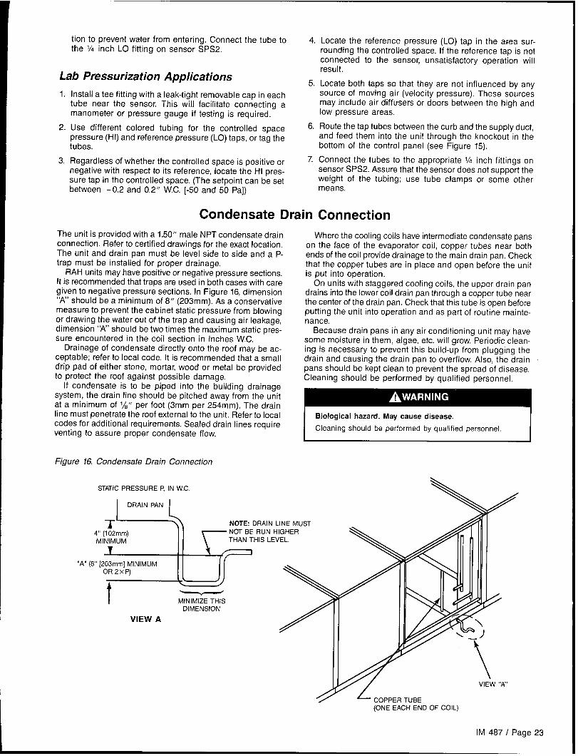
The unit is provided with a 1.50” male NPT condensate drain Where the cooling coils have intermediate condensate pansconnection. Refer to certified drawings for the exact location.The unit and drain pan must be level side to side and a P-trap must be installed for proper drainage.
RAH units may have positive or negative pressure sections.It is recommended that traps are used in both cases with caregiven to negative pressure sections. In Figure 16, dimension“A” should be a minimum of 8“ (203mm). As a conservativemeasure to prevent the cabinet static pressure from blowingor drawing the water out of the trap and causing air leakage,dimension “A’ should be two times the maximum static pres-sure encountered in the coil section in inches W.C.
Drainage of condensate directly onto the roof may be ac-ceptable; refer to local code. It is recommended that a smalldrip pad of either stone, mortar, wood or metal be providedto protect the roof against possible damage.
If condensate is to be piped into the building drainagesystem, the drain line should be pitched away from the unitat a minimum of 1/8” per foot (3mm per 254mm). The drainline must penetrate the roof external to the unit, Refer to localcodes for additional requirements. Sealed drain lines requireventing to assure proper condensate flow.
Figure 16. Condensate Drain Connection
STATIC PRESSURE P, IN W.C.
I
DRAIN PAN
L
“A”
L
II \\\
on the face of the evaporator coil, copper tubes near bothends of the coil provide drainage to the main drain pan, Checkthat the copper tubes are in place and open before the unitis put into operation.
On units with staggered cooling coils, the upper drain pandrains into the lower coil drain pan through a copper tube nearthe center of the drain pan, Check that this tube is open beforeputting the unit into operation and as part of routine mainte-nance.
Because drain pans in any air conditioning unit may havesome moisture in them, algae, etc. will grow, Periodic clean-ing is necessary to prevent this build-up from plugging thedrain and causing the drain pan to overflow, Also, the drainpans should be kept clean to prevent the spread of disease.Cleaning should be performed by qualified personnel.
Biological hazard. May cause disease.
Cleaning should be performed by qualified personnel.
T’ --ii NOTE: DRAIN LINE MUST
4“ (102mm) NOT BE RUN HIGHER
MINIMUM THAN THIS LEVEL.
T
(8” [203mm] MINIMUM ((
OR2XP)
t
““’ 3
\
MINIMIZE THISDIMENSION
VIEW A
4VIEW ‘W’
- COPPER TUBE(ONE EACH END OF COIL)
IM 487 I Page 23

Field Refrigerant Piping and Charging of DX Coils
RAH units that ship from the factory with DX coils installeddo not include refrigerant piping or refrigerant controls. Thecoil assembly is ready for field connections at the distributorsand at the suction headers. Piping kits that provide thenecessary liquid and hot gas piping and control componentsare available for field installation.
Field installed refrigerant piping may exit the unit cabinetat one of the following locations:1. Through the floor of the unit.2. Through the discharge and bulkhead of the unit.3. Through a cabinet door near the DX coil that is not required
for service areas.
Caution: For any of the above cabinet penetrations, the holemust be tightly sealed to prevent water or air leakage.
In preparing for field piping, the plastic plugs on the distribu-tors must be removed and the copper caps at the suctionheader connections must be unsweated.
Piping design, sizing, and installation information presentedin ASH RAE handbooks should be followed in the design andinstallation of interconnecting piping. The DX coil and con-densing unit are intended to be set at the same elevation,as close as possible to each other to minimize refrigerantpressure drop. The piping must be designed and installed toprevent liquid refrigerant carryover to the compressor and toassure a continuous return of compressor oil from the system.
The pounds of refrigerant in the system may exceed thecapacity of the condenser, depending on the amount ofrefrigerant in the liquid lines between the DX coil and thecondensing unit. Refer to condenser manufacturer for in-formation about refrigerant capacity. Suitable means ofcontaining the refrigerant is required.
~
On systems with optional hot gas bypass, it is importantthe bypass solenoid valve be located at the condensingunit and not at the DX coil to prevent liquid return and
Piping Recommendations1. Use type K or L clean copper tubing. All joints should be
thoroughly cleaned and brazed with high temperaturesolder.
2. Piping sizes should be based on temperature/pressurelimitations as recommended in the following paragraphs.Under no circumstances should pipe size be based strict-ly upon the coil or condensing unit piping connection size.
3. Suction line piping pressure drop should not exceed thepressure equivalent of 2° F (-17C) for R-22 (3 psi [21 kPa])per 100 feet (30.5m) of equivalent pipe length. After thesuction line size has been determined, the vertical suc-tion risers should be checked to verify that oil will be car-ried up the riser and back to the compressor. The suctionline(s) should be pitched in the direction of refrigerant flowand fully insulated between the evaporator(s) and thecompressor.
4. Vertical suction risers should be checked using Table 4to determine the minimum tonnage required to carry oilup suction risers of various sizes.
5.
6.
Suction lines within the unit cabinet must be insulated toprevent dripping of condensation.
The liquid line should be sized for a pressure drop not toexceed the pressure equivalent of 20F (-17C) for R-22 (6psi [41 kPa]) saturated temperature. The RAH unit includesa factory installed filter-drier, solenoid valve, and sightglassin each liquid line, upstream of the thermal expansionvalve,
Table 4. Minimum Tonnage (R-22) to Carry Oil L@ SuctionRiser at 40 OF Saturated Suction
Line Size11A 13h 15h 2% 2% 31A 35h 41~
O.D. (In.)
Minimum
Tons1,50 2.50 3.80 7.60 13.10 20.4 29.7 41.3
Note: When compressor minimum tonnage is less than shown in the abovetable for a given line size, double suction risers will be required.
Leak TestingThe field piping system should be checked for leaks prior tocharging. Leak testing must be performed to current EPAstandards and regulations. After making any necessary re-pair, the system should be evacuated as described in thefollowing paragraphs.
A serious explosion could result from using oxygen tobuild up pressure resulting in severe personal injury ordeath.
I Do not use oxygen to build up pressure. I
EvacuationAfter it has been determined that the unit is tight and thereare no refrigerant leaks, the system should be evacuated. Theuse of a vacuum pump with a pumping capacity of approxi-mately 3 cu. ft./rein. (1.4 L/see.) and the ability to reduce thevacuum in the unit to at least 1 millimeter (1000 microns) isrecommended.
1.
2.
3.
A mercury manometer or an electronic or other type ofmicron gauge should be connected to the unit at a pointremote from the vacuum pump. For readings below 1millimeter, an electronic or other micron gauge should beused.
The triple evacuation method is recommended and is par-ticularly helpful if the vacuum pump is unable to obtainthe desired 1 millimeter of vacuum. The system is firstevacuated to approximately 29 inches (737mm) of mercury.Enough refrigerant vapor is then added to the system tobring the pressure up to O pounds.
Then the system is once again evacuated to 29 inches(737mm) of vacuum. This procedure is repeated threetimes. This method can be most effective by holding systempressure at O pounds for a minimum of 1 hour betweenevacuations. The first pulldown will remove about 90% ofthe noncondensables, the second about 90% of that re-maining from the first pulldown, and after the third, only1/10 of 1% noncondensables will remain.
Page 24 I IM 487

I
Table 5 below shows the relationship between pressure, microns, atmospheres, and the boiling point of water.
Table 5. Pressure-Vacuum Equivalents
Absolute Pressure Above Zero Vacuum Below one Atmosphere Approximate Boiling Point
Mercury MercuryMicrons Psia
Fraction of of HzO at Each
(mm) (Inches) One Atmosphere Pressure 0F (0 C)
o 0 760.00 29.921 — —
CJnn – W-1 (. A6. C),L”” 1 =- , ,- -, I50 0.001 759.95 29.920 1/15,:
100 0.002 759.90 29.920 117,600 -40 (-40” C)
150 0.003 759.85 29.920 1/5,100 -33 (-36 ‘C)
200 0,004 759.80 29.910 113,800 -28 (-33° C)
300 0.006 759.70 29.910 112,500 -21 (-29oC)
500 0.009 759.50 29.900 Ill ,520 -12 (-240C)
1,000 0,019 759.00 29.880 11760 1 (-17” C)
2,000 0.039 758.00 29.840 11380 15 (-9”C)
4,000 0.078 756.00 29.760 1/169 29 (-2°C)
6,000 0.117 754.00 29.690 1/127 39 (4” c)
8,000 0.156 752.00 29.600 1/95 46 (80C)
10,000 0.193 750.00 29.530 1176 52 (I IoC)
15,000 0.290 745.00 29.330 1/50 63 (170C)
20,000 0.387 740.00 29.130 1138 72 (220C)
30,000 0.580 730.00 28.740 1125 84 (29oC)
E==50,000
100,000200,000500,0007Gr-1 mm EB=t
710.00 27.950 1/15 101 (380C)
660.00 25.980 2115 125 (52” C)
560.00 22.050 114 152 (67”C)
260.00 10.240 2/3 192 (89oC)
n o 1 Atmosphere 212 (loo”c)
Charging the System1.
2.
3.
4.
After all refrigerant piping is complete and the system hasbeen evacuated, it can be charged as described in theparagraphs following. Connect the refrigerant drum to thegauge port on the liquid shutoff valve, and purge the charg-ing line between the refrigerant cylinder and the valve.Then open the valve to the midposition.
If the system is under a vacuum, stand the refrigerant drumwith the connection up, open the drum and break thevacuum with refrigerant gas.
With a system gas pressure higher than the equivalentof a freezing temperature, invert the charging cylinder andelevate the drum above the condenser. With the drum inthis position and the valves open, liquid refrigerant will flowinto the condenser. Approximately 75% of the total require-ment estimated for the unit can be charged in this manner.
After 75% of the required charge has entered the con-denser, reconnect the refrigerant drum and charging lineto the suction side of the system. Again purge the connect-ing line, stand the drum with the connection side up, andplace the service valve in the open position.
Important: At this point, the charging procedure should beinterrupted and prestart checks made before attempting to
complete the refrigerant charge.
Note: It is recommended that the total operating charge percircuit be stamped on the unit nameplate for future reference.
Refrigerant ChargeFactory installed DX coils in RAH units are designed for usewith R-22. The total system charge is the sum of three values:1. Condensing unit charge—refer to manufacturer’s data.2. Evaporator coil charge—refer to Table 6.3. Charge for length of interconnecting piping installed by
field—refer to Table 7.
Note: Factory installed DX coils are intended for two refriger-ant circuits containing identical weights of refrigerant. Thevalues shown in Tables 6 and 7 are for each circuit.
Note: The total operating charge per circuit should not ex-ceed the pumpdown capacity per circuit, specified by the con-densing unit manufacturer.
Table 6. Approximate DX Coil Refrigerant Charge Per Circuit
Unit DX Coil R-22 Chsrge (Lbs./Circuit)
Size Flat Coil Staggered Coil
047C 3x No. Of DX ROWS 3.5 x No. of DX flowS
077C 5 x No. of DX flOWS 6.5 X No. Of DX ROWS
Table 7. Weight of Refrigerant R-22 in Copper Lines (Pounds Per 100 Feet of Type L Tubing)
Volume Per 100 FeetWeight of Refrigerant, Lbs./100 Feet
O.D. Line Sizein Cubic Feet Liquid @ 100” F
Hot GSS @ 120” F Suction Gaa (Superheated to 85” F)
Cond. 20” F 40” F
% 0.054 3.84 .202 .052 .077V2 0.100 7.12 .374 .098 .143
518 0.162 7,12 .605 .158 .232
‘/8 0.336 24.0 1.260 ,323 .48011/s 0.573 40.8 2.140 .550 .8201% 0.872 62.1 3.260 .839 1.25015/8 1.237 88.0 4.620 1.190 1.77027/s 2.147 153.0 8.040 2.060 3.060278 3.312 236.0 12.400 3.180 4.7203% 4.728 336,0 17.700 4.550 6.75035/, 6,398 456.0 24.000 6.150 9.14041~ 8.313 592.0 31.100 8.000 11.190
IM 487 / Page 25
Unit Piping
Gas PipingSee the “installation” section of the gas fired furnace installa-tion manual, Bulletin No. IM 484.
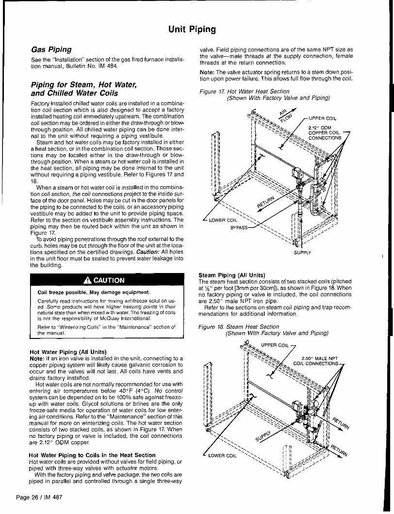
Piping for Steam, Hot WateRand Chilled Water CoilsFactory installed chilled water coils are installed in a combina-tion coil section which is also designed to accept a factoryinstalled heating coil immediately upstream. The combinationcoil section may be ordered in either the draw-through or blow-through position. All chilled water piping can be done inter-nal to the unit without requiring a piping vestibule.
Steam and hot water coils may be factory installed in eithera heat section, or in the combination coil section. These sec-tions may be located either in the draw-through or blow-through position. When a steam or hot water coil is installed inthe heat section, all piping may be done internal to the unitwithout requiring a piping vestibule. Refer to Figures 17 and18.
When a steam or hot water coil is installed in the combina-tion coil section, the coil connections project to the inside sur-face of the door panel. Holes maybe cut in the door panels forthe piping to be connected to the coils, or an accessory pipingvestibule may be added to the unit to provide piping space.Refer to the section on vestibule assembly instructions. Thepiping may then be routed back within the unit as shown inFigure 17.
To avoid piping penetrations through the roof external to thecurb, holes may be cut through the floor of the unit at the loca-tions specified on the certified drawings. Caution; All holesin the unit floor must be sealed to prevent water leakage intothe building.
Coil freeze possible. ,May damage equipment.
Carefully read instructions for mixing antifreeze solution us-ed. Some products will have higher freezing points in theirnatural state than when mixed with water. The freezing of coilsis not the responsibility of McQuay International.
Refer to “Winterizing Coils” in the “Maintenance” section ofthe manual.
Hot Water Piping (All Units)Note: If an iron valve is installed in the unit, connecting to acopper piping system will likely cause galvanic corrosion tooccur and the valves will not last. All coils have vents anddrains factory installed.
Hot water coils are not normally recommended for use withentering air temperatures below 40 F (40C), No controlsystem can be depended on to be 100% safe against freeze-UP with water coils. Glycol solutions or brines are the onlyfreeze-safe media for operation of water coils for low enter-ing air conditions. Refer to the “Maintenance” section of thismanual for more on winterizing coils. The hot water sectionconsists of two stacked coils, as shown in Figure 17. Whenno factory piping or valve is included, the coil connectionsare 2.12” ODM copper.
Hot Water Piping to Coils in the Heat SectionHot water coils are provided without valves for field piping, orpiped with three-way valves with actuator motors.
With the factory piping and valve package, the two coils are
piped in parallel and controlled through a single three-way
valve. Field piping connections are of the same NPT size asthe valve—male threads at the supply connection, femalethreads at the return connection.
Note: The valve actuator spring returns to a stem down posi-tion upon power failure. This allows full flow through the coil.
Figure 17 Hot Water Heat Section(Shown With Factory Valve and Piping)
SUPPLY
Steam Piping (All Units)The steam heat section consists of two stacked coils (pitchedat 1/8“ per foot [3mm per 30cm]), as shown in Figure 18. Whenno factory piping or valve is included, the coil connectionsare 2.50” male NPT iron pipe.
Refer to the sections on steam coil piping and trap recom-mendations for additional information.
Figure 18. Steam Heat Section(Shown With Factory Valve and Piping)
Page 26 I IM 487

Steam Piping to Coils in the Heat SectionSteam coils are provided without valves for field piping, orpiped with two-way valves and actuator motors.
With the factory piping and valve package, the two coil sup-plies are piped in parallel and controlled through a single two-way valve. The field supply connection is of the same femaleNPT size as the valve. Field return connections are made atthe 2.50” male NPT fittings on each of the two stacked coils.
Note: The valve actuator spring returns to a stem up posi-tion upon power failure. This allows full flow through the coil.
Pipinq Recommendations (Steam Coils)1.”
2.
3.
4.
5.
6.
Be-certain that adequate piping flexibility is provided.Stresses resulting from expansion of closely coupled pip-ing and coil arrangement can cause serious damage.
Do not reduce pipe size at the coil return connection. Carryreturn connection size through the dirt pocket, making thereduction at the branch leading to the trap.
It is recommended that vacuum breakers be installed onall applications to prevent retaining condensate in the coil.Generally, the vacuum breaker is to be connected betweenthe coil inlet and the return main. However, if the systemhas a flooded return main, the vacuum breaker should beopen to the atmosphere and the trap design should allowventing of the large quantities of air.
Do not drain steam mains or take-offs through coils. Drainmains ahead of coils through a steam trap to the return line.
Do not attempt to lift condensate when using modulatingor on-off control.
Pitch all supply and return steam piping down a minimumof 1 inch per 10 feet (3mm per 305cm) in direction of flow.
Steam Trap Recommendations1.
2
3.
4.
!5.
Size traps in accordance with manufacturers’ recommen-dations. Be certain that the required pressure differentialwill always be available. Do not undersize.
Float and thermostatic or bucket traps are recommendedfor low pressure steam. Use bucket traps on systems withon-off control only.
Locate traps at least 12 inches (305mm) below the coilreturn connection.
Always install strainers as close as possible to the inlet sideof the trap.
A single trap may generally be used for coils piped inparallel, but an individual trap for each coil is preferred.
Figure 19. Heating Coil Piping With Vestibule
Freeze Conditions (Steam Coils)(Entering air temperature below 350 F [20 C])1. 5 PSI (34.5 kPa) steam must be supplied to coils at all
times.
2. Modulating valves are not recommended. Control should
3.
4.
be by means of face and bypass dampers.
As additional protection against freeze-up, the trap shouldbe installed sufficiently far below coil to provide an ade-quate hydrostatic head to ensure removal of condensateduring an interruption on the steam pressure. Estimate 3feet (914mm) for each 1 PSI (6.9 kPa) of trap differentialrequired.
If the unit is to be operated in environments with possiblefreezing temperatures, an optional freezestat is recom-mended. Refer to “Freeze Protection” in the “Unit Options”section of this manual.
Chilled Water PipingChilled water coils are provided without valves for field pip-ing, or piped with three-way valves with motor actuators. Table8 provides information on units with factory installed pipingand valve packages. The table also provides field sweat con-nection information for units not furnished with factory installedpiping and valve packages.
With the factory piping and valve package, the coil assemblyis controlled through a single three-way valve. When two coilsare included in the assembly, they are piped in parallel. Fieldconnections are male NPT, sized as shown in Table 8. Referto Figure 20 for a typical cooling coil with factory valve andpiping.
Fiaure 20. Chilled Water Coil(Shown With Factory Valve and Piping)
IM 487 I Page 27

Table 8. Piping Connection SizeslValve Size Options For Chilled Water Piping
y
Hx83° i
2108mm)’
Long
33+ 33
(2 Coils)
(838 +
838m)
Available CircuitingFace
Available 5WH 5WL 5WS 5WM 5WDArea
Sq. Ft.Rows*” Columns
(Sa. m) 123 123 1z3 123 123
Application/
Code:abinet
Size
3 DKR DKQ A Q A Q A P
4 DKR DKQ BJQ BJQ BJP5 DKR DKQ A Q BJQ A P
6 DKR DKQ BJQ BJQ A P
8 DKR DKQ BJQ BJQ BJP3 DKR CJQ A Q A Q A P
4 DKR CJQ cJQ cJQ BJF’5 DKR CJQ A Q CJQ A P
6 DKR CJQ cJQ CJQ A P
8 DKR CJQ CJQ CJQ BJP3 FLU EKT A s A s A s
27.7 4 FLU EKT cJs cJs CJS(2.57m2) 5 FLU EKT A s CJS A s
6 FLU EKT cJs cJs A s
8 FLU EKT cJs cJs CJSQ A Q A Q A P
,I A nKRICJQ CJQ cJQ BJP
n c .1 Q A P
Blow-thru or Draw-thru
Small Coil Section
38.0
(3.53mZ)
39+ 39
(2 Coils)
(991 +
991 mm)
Blow-thru or Draw-thru
Large Coil Section
45.0
(4.18mZ)
047C
Face & Bypass Section
With Small Coil
48
1219mm)
39+ 39
(2 Coils)
(991 +
991 mm)
m
?. I DKRICJ
Face & Bypass Section
With Large Coil
45.0 “~KRICJQ 1A
(’$18M2) ~lDKRICJQICJ ;l;~QIA
1
‘1
RIC J QIC
3 CJR cJQ IA
4 CJR CJQIC51.9 JR CJI
(4.82m2) ; ~JR CJQ CJ
8 CJR CJQ cJ3 BJQ BJp A
4 BJQ BJp B72.6 5 BJQ BJp A
(6.74m2) ~ BJQ BJp BJ8 BJQ BJ“ r ,/ T PI
45+ 45
(2 Coils)
(1143 +
1143mm)
63+ 63
(2 Coils)
(1600 +
1600mm)
Blow-thru or Draw-thru
Small Coil Section
Blow-thru or Draw-thru
Large Coil Section
BJ-,
1 I
077C ,,,. I
436.3
EKTICJS cJsl(
3.37mZ)5 EKTICJS A SICJ
6 E
8 EKTICJS cJs[~Js!c L3 CJRICJQ A rim
Face & Bypass Section
With Small Coil
63
1600mm) K TICJ sIc JSICJS IA sI .s~
A “1. P A P
r. Ic. IRIc JQIBJ PIBJp BJPRICJQIA PIBJP A P
P A P
54+ 54
(2 Coils)
(1372 +
Face & Bypass SeCtiOn
With Large Coil
62.3 ; ;;
:5.74mZ) 6 CJR CJQ BJP BJ8 CJR CJQ BJP BJPIBJP3 CJR CJQ A P A PIA P
1 ,.1
1372mm)
“Available with 8, 10, or 12 fins per
Column 1:These units are available with a factory installed package consisting of a three-way water valve and connecting piping.
A = This combination is not available with a factory installed piping and valve package.B = 3.00, 2.50, or 2.00 inch three-way valves can be specifiedC = 3.00, 2.50, 2.00, or 1.50 inch three-way valves can be specifiedD = 250, 2.00, or 1.50 inch three-way valves can be specifiedE = 2.50, 2.00, 1.50, or 1.25 inch three-way valves can be specifiedF = 2.00, 1.50, or 1.25 inch three-way vales can be specified
Column 2:The pipinglvalve package terminates as male pipe threads for connection to the field supply and return water piping:
J= 3.00-8 NPT male, supply and return connectionsK = 2.50-8 NPT male, supply and return connectionsL = 2.00-11 NPT male, supply and return connections
Column 3:Units that are not furnished with the factory installed piping/valve package require field sweat connections,
at one or two coils, to male copper tubing for the
supply, and return water pipin9:
P = Two 3.12 O.D. supply and two 3.12 O.D. return connectionsQ = Two 2.62 O.D. supply and two 2.62 O.D. return connectionsR = Two 2.12 O.D. supply and two 2.12 O.D. return connectionsS = One 3.12 O.D. supply and one 3.12 O.D. return connectionsT = One 2.62 O.D. supply and one 2.62 O.D. return connectionsU = One 2.12 O.D. supply and one 2.12 O.D. return connections
Page 28 I IM 487

Vestibule Assembly Instructions
An accessory vestibule is available to provide additional pip- Figure 21a.
ing space for coils installed in a four-foot section. A vestibuleis required to maintain door access on a combination heatingand cooling section. The vestibule should be assembled tothe unit part by part as shown in Figure 21. Note: The door,hinge, and latch assemblies from the unit are used on thevestibule.
Step 1Remove door from section where vestibule is to be locatedby removing screws holding hinges to upright support (leavehinges on door). Set door aside and save for Step 4.
Remove door latch assembly from other side upright sup-port. Use offset Phillips screwdriver or a wrench to removescrews holding latch assembly in place. Save door latchassembly, screws and bushings for Step 4.
Step 2Remove gasketing around door flange and save for use onvestibule. See Step 4. Remove door and save for Step 4.
GASKET1NG
- DOOR
\
\
..
1.I
w
\DOOR LATCH ASSEMBLY
Figure 21b.
OOOR PROP/
IM 487 I Page 29
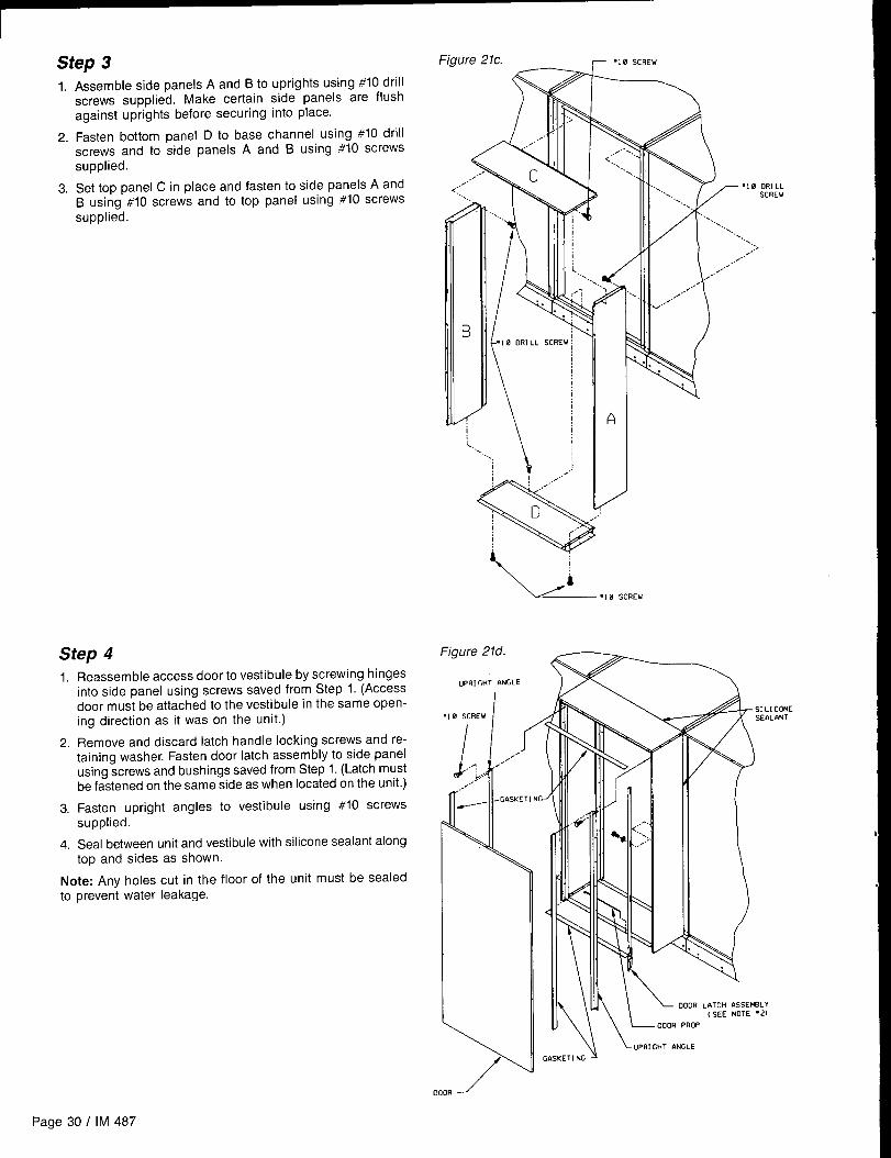
I Step 3
~1.
2.
3.
Assemble side panels A and B to uprights using #10 drillscrews supplied. Make certain side panels are flushagainst uprights before securing into place.
Fasten bottom panel D to base channel using #10 drillscrews and to side panels A and B using #10 screwssupplied.
Set top panel C in place and fasten to side panels A andB using #10 screws and to top panel using #10 screws
supplied.
Step 4
1.Reassemble access door to vestibule by screwing hingesinto side panel using screws saved from Step 1. (Accessdoor must be attached to the vestibule in the same open-ing direction as it was on the unit.)
2. Remove and discard latch handle locking screws and re-taining washer. Fasten door latch assembly to side panelusing screws and bushings saved from Step 1. (Latch mustbe fastened on the same side as when located on the unit.)
3. Fasten upright angles to vestibule using #10 screwssupplied.
4. Seal between unit and vestibule with silicone sealant alongtop and sides as shown.
Note: Any holes cut in the floor of the unit must be sealedto prevent water leakage.
I
Figure 21c. ~ ‘1 0 SCREW
<:
\ /i
r
— ., 0 SCREW
7010 DRILL. ..\ SCREW
.. ... .
......
“..‘. ...
.:>,,,,..
,.,/.”
,.,,,,
..~/,”’
Figure 21d.----
UPRIGHT ANGLE
‘1 0 SCREW I
\ /“
4S[ LI CONESEIIL~NT
%\\ iuPtN GHT 14NGLE
G~SKETI NC>
Page 30 / IM 487

Damper Assemblies
The optional damper assemblies described in this section are The outside air return air damper assembly (economizer)provided with manually adjustable linkages, or maybe ship- comes with manually adjustable linkage. This adjustable link-ped with factory installed actuators and linkages in units that age can also be used for connection of a damper operator.include factory controls. The damper is set so that the crankarm moves through a
Economizer Dampers90-degree angle to bring the economizer dampers from fullopen to full close. Mechanical stops have been placed in the
Outside air intake is provided on both sides of the unit, and crankarm mounting bracket. Do not remove stops. If crankarm
the return air path is at the center of the damper set. As the is driven past stops, damage to linkage or damper will result.
single actuator modulates the outside air dampers open, the The unit will ship with a shipping bolt securing the linkage
return air dampers close. Exhaust air exits the unit through crankarm. Remove shipping bolt before use.
the gravity relief dampers provided at the end of theeconomizer section.
Figure 22a. Figure 22b.
OUTSIDE- OPTIONAL RETURN AIR FAN
AIR
Q /’ ,“ - ‘cONOM1zER
d,_-–r
1--11II
/ ,,
‘-rI ____
G
OUTSIDE \AIR
Figure 22c. /
/
--->
,-—...-—-..-—.—..— .— ..—— . . .-—...—;
)/’..
/,
\
90 . . . .
- STROKE .OA CLOSEDX
~.:T- ., ;$ OA OPEN ](,–1 -’s .25” (6mm); . . ,.
1 ‘J @
}- -–-—--- .; J:>&- # ,
. ‘,? ‘ /’ 1.6 \;...— .-.-~
1.—— –,-+ .
~ #
.500 (13mm) Dis. Shafl ‘ ~@
(-)
/ I (~> x 1.30” (33mm) Long , ;\._ -__ ... L_.z.v_—_- &,--—...’_ . . . . — -- —-. - . .. .
Note: For good airflow control, adjust linkages so damper blades do not open
beyond 70 degrees. Opening a damper blade beyond 70 degrees has little
effect on its airflow.
Do not “overclose” low leak damper blades. The edge seal should just lightly
contat the adjoining blade. The blades will lock up if they are closed so far
the seal goes over center.
IM 487 I Page 31
I

Intake Hood Damper (O to 100% Outside Air)Units requiring 100’% outside air are provided with a rain hood vides two position control for opening the dampers fully dur-
and dampers which may be controlled by a single actuator. ing unit operation and closing the dampers during the off cy-
The actuator, which may be ordered with factory controls, pro- cle. No unit mounted exhaust dampers are provided.
Figure 23a/\..
Figure 23b
~----- _—. .——
)/90 -’-. )
OA CLOSED ,Z sTRoKE ,, ~A OPEN_.—c-
/’~‘ .25” (6m~)‘.”.
--.—,:>,)&t. ,Q6\
—.. —.— -.%&+.500” (13mm) -’.75” ‘ 0Dia. Shaft (19mm)~
“1
Note: For good airflow control, adjust iinkages sodamper blades do not open beyond 70 degrees. Open-ing a damper blade beyond 70 degrees has little effect
on its airflow.
Do not “overclose” low leak damper blades. The
edge seal should just lightly contat the adjoining blade.
The blades will lock up if they are closed so far the seal
goes over center.
.,. ,..-- ._. _.,
Intake Hood Damper (O to 30% Outside Air)These dampers are intended to remain at a fixed position dur-ing unit operation, providing fresh air quantities from Oto 30%of the total system airflow, depending on the damper setting.This setting is,made at the linkage rod on units with manual-ly adjustable linkages.
On units provided with MicroTech controls, the damper posi-tion may be set at the controller keypad. During unit opera-tion, the two-position actuator drives the damper to the posi-tion set on the keypad. During the off cycle, the damper isautomatically closed.
No unit mounted exhaust dampers are provided with thisoption.
\\
/
Figure 24
I
\
!,1,/
Ii
/
/
!,
/
,L
13.15“ (80mm) MAX. STROKE OFDAMPER LINKAGE BAR
Page 32 I IM 487

Mixing BoxThis section utilizes a outside air damper and a return airdamper, Use of these dampers allows outside air to beblended with return air. Synchronized operation of thedampers is accomplished by interconnecting rods. As onedamper section opens, the other section is being closed.Always a total of100% CFM is drawn from this section,Damper positioning may be either manually or automaticallyadjusted. With a field installed controller, automatic operationcan be obtained,
These dampers provide a similar function to the economizerdampers. This option differs from an economizer in that nounit mounted exhaust dampers are provided,’
Figure 25b
Figure 25a
—
Top View of Mixing Box
I –
I .
—
—.—.—.—..---------.- p-q--qIllIll
;1III
\il 1
‘4. ; ;l\ll1.1I \l 1
), :I
l’\l.1
11}I ‘>
;11
;11 1
tIll
;11
II I 1I
;1I
1
;1I I
IIll
.-,---, -- J-
—.—.—.—-----II
II 1
I 1
iiI
11
1 11
II
! 1III
;1I
1 1II
:\% ;
; \,;
N1 1.,II
‘\1 1I 1 ‘\\=. & ._. :
OACLOSED
Note: For good airflow control, adjust linkages so damper blades do not openbeyond 70 degrees. Opening a damper blade beyond 70 degrees has littleeffect on its airflow.
Do not “overclose” low leak damper blades. The edge seal should just lightlycontat the adjoining blade. The blades will lock up if they are closed so farthe seal goes over center.
Crankarm
IM 487 I Page 33
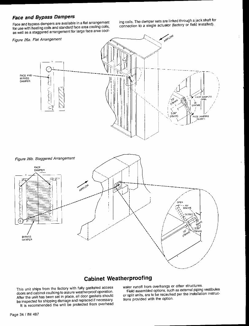
Face and Bypass DampemFace and bypass dampers are available in a flat arrangement
ing coils. The damper sets are linked through a jack shaft for
for use with heating coils and standard face area cooling coils,connection to a single actuator (factory or field installed).
as well as a staggered arrangement for large face area cool-
Figure 26a. Flat Arrangement .~<\
DAMPER It,,b,, 1 I /1;
Figure 26b. Staggered
FACEDAMPER
BYPASSDAMPER
Ill ‘1
d’ ,j,’”/’
,/’‘\, i .’
..~”.”
:>.,\
< -–
;/
“ \
\.
/,;7’
+“
--— .
\ \‘, .
,//
/’
,,’ ‘ 1“-.. , -.
/
Arrangement ‘\\ .
~d’j
x. /’‘;?”
/’ I‘\., /
,/”‘.. ,
/
,/ -7’i ,- s Yi---- -- --------“++ ]4.- ,) ‘ ------- -----------_=_ ~~$s+
--/ t’ \\ i .-
4
-.,~-- , , ,,,, - ..
e~OO , \ ,,/ \..\
e-”-
(
.,/ \\l#- .,x, I J
/..- ,’ OPEN
\,1
e.e”
‘!
11 /’ ,,’ --- go. \
\ /“ / 11 ‘!
~\\ ,,/’ ,$,, \\ STROKE \
/~/~\\
,;’ \\\,\\ ‘\\ \\,,
F’
1\\x\\ CLOSED’ “
,,/
/’\
\\\\\\
/’\ ;/ \,;h,,
\
,/’ \\\
:*\,,/
\‘$, I i
\ /’
\3.00” ,/
\\
f Is .@ X(76mm)
\ ;g$
J
i\ ,’\’\ ,,/
\ o t\l\\ : ,/:-, \\:\\\,
/
,/Y
+,%/
.
\,,’/
\ ,/”“,.. .,/’
\.__.. /O
Cabinet Weatherproofing
This unit ships from the factory with fully gasketed accesswater runoff from overhangs or other structures.
doors and cabinet caulking to assure weatherproof operation.Field assembled options, such as external piping vestibules
After the unit has been set in place, all door gaskets shouldor split units, are to be recaulked per the installation instruc-
be inspected for shipping damage and replaced if necessary.tions provided with the option.
It is recommended the unit be protected from overhead
page 34 I IM 487

Electrical Installation
Without Optional Electrical
Field Power Wiring
Power PackageAll of the unit side panels are hinged. Disconnect switches water Ieakage,and/or motor starters must not be mounted on panels which Conduits connecting the unit to external panels will be sub-provide access to internal components. Wiring’ conduits can jetted to relative humitidy and air pressure differentials and
sealed. Motor should be grounded us-corrosion resistant conductor.
penetrate the cabinet bottom, base frame or through the hinge therefore should beand latch cap without interfering with the access panels. ing copper or other
Note: All holes cut into the unit must be sealed to prevent
Figure 27TOP
/ l-d = HINGE ANDACCESS LATCH CAP
PANELS
With Optional Electrical Power PackageWiring must comply with all applicable codes and ordinances.The warranty is voided if wiring is not in accordance with thesespecifications.
According to the National Electrical Code, a disconnectingmeans shall be located within sight of and readily accessiblefrom the air conditioning equipment. The unit may be orderedwith an optional factory mounted disconnect switch. Thisswitch is not fused. Power leads must be overcurrent protectedat the point of distribution. The maximum allowable overcur-rent protection is shown on the unit nameplate.
RAH units may be ordered with internal power wiring foreither single or multiple point power connections. If singlepoint power is ordered, a single power block or an optionaldisconnect switch is located within the main control panel.Field power leads are brought into the unit through 3-inchknockouts in the bottom of the main control panel. Refer toFigure 28.
Units ordered with dual point power connections are pro-vided with nonfused, factory mounted disconnect switches.Disconnect DS1 handles the fan load and controls, and ismounted within the main control panel. Disconnect DS3handles the electrical heat load and is located within the elec-tric heat control panel.
Hazardous voltage. May cause severe injury or death.
Disconnect electric power before servicing equipment. Morethan one disconnect may be required to de-energize the unit,
The minimum circuit ampacity (wire sizing amps) is shownon the unit nameplate. Refer to Table 9 for recommendednumber of power wires.
Table 9. Recommended 3-Phase Power Wiring*
For MCAUP To
(Amps)
304055
708595
130150175
200230255
285310335
380400460
510570620
670760765
855930
WireGauge
1o“86
432
11/02/0
3/04/0250
300350400
5003/05/0
250300350
400500250
300350
Tlnsul-
Qty.1 ationPole Rating
(“c)
1 601 60
=
1 60
1 601 601 60
1 751 751 75
1 751 751 75
1 751 I 75
T1 75
1 752 752 75
2 752 75
*
2 75
2 752 753 75
3 I 753 I 75
No. Of:onduits
111
111
111
111
11
1
122
222
223
33
tBOTTOM
(TrsdeSize, In.)
7/2
3/4
1
I 1A
I 1/4
11~
11A
I 1/2
2
2221/2
21/2
33
32221/2
21/2
3
3321/2
21/2
‘To assure that disconnects and power blocks mate with power wiringNotes:1. All wire sizes assume separate conduit for each set of parallel conductors.2. All wire sizes based on NEC Table 310-16 for THW wire (copper). Cana-
dian electrical code wire ampacities may vary,3. All wire sizes assume no voltage drop for short power leads.
IM 487 I Page 35
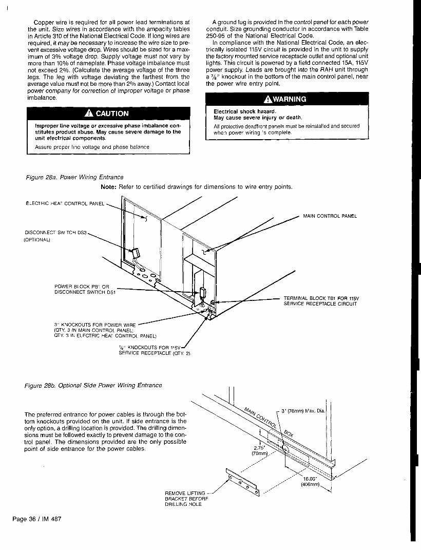
Copper wire is required for all power lead terminations atthe unit. Size wires in accordance with the ampacity tablesin Article 310 of the National Electrical Code. If long wires arerequired, it maybe necessary to increase the wire size to pre-vent excessive voltage drop. Wires should be sized for a max-imum of 3% voltage drop. Supply voltage must not vary bymore than 10% of nameplate. Phase voltage imbalance mustnot exceed 2%. (Calculate the average voltage of the threelegs. The leg with voltage deviating the farthest from theaverage value must not be more than 2% away.) Contact localpower company for correction of improper voltage or phaseimbalance.
Improper line voltage or excessive phase imbalance con-stitutes product abuse. May cause severe damage to theunit electrical components.
Assure proper line voltage and phase balance.
A ground lug is provided in the control panel for each power
conduit. Size grounding conductor in accordance with Table250-95 of the National Electrical Code.
In compliance with the National Electrical Code, an elec-trically isolated 115V circuit is provided in the unit to supplythe factory mounted service receptacle outlet and optional unitlights. This circuit is powered by a field connected 15A, 115Vpower supply. Leads are brought into the RAH unit througha 7/8“ knockout in the bottom of the main control panel, nearthe power wire entry point.
Electrical shock hazard.May cause severe injury or death.
All protective deadfront panels must be reinstalled and securedwhen power wiring is complete.
Figure 28a. Power Wiring Entrance
Note: Refer to certified drawings for dimensions to wire entry points.
ELECTRIC
CONTROL PANEL
OISCONNE
(OPTIONAL)
OCK Tel FOR 115VEPTACLE CIRCUIT
‘k” KNOCKOUTS FOR I15V 1
SERVICE RECEPTACLE (QTY. 2)
Figure 28b. Optional Side Power Wiring EntranceII
The preferred entrance for power cables is through the bot-tom knockouts provided on the unit. If side entrance is theonly option, a drilling location is provided. The drilling dimen-sions must be followed exactly to prevent damage to the con-trol panel. The dimensions provided are the only possiblepoint of side entrance for the power cables.
.=”.-”’ .,. . ... ,,,’”
A
.,,,.,’,,.
a .,,B ,., (406mm)
,,-REMOVE LIFTING o ,,, 4
BRACKET BEFOREDRILLING HOLE
Page 36 I IM 487

Field Control Wiring
The control wiring should be connected as shown on the wir-ing diagrams provided with the unit. Units are available with
a number of optional control arrangements. Specific field wir-ing connections for these arrangements are described in thesections on unit and control options.
If unit mounted control devices are to be installed in thefield, control wiring may be run from the device to the maincontrol box using the control wiring raceway shown in Figure29. Field wired harnesses must be wired, to terminal blocksTB2, TB5, TB7, TB8 or TB1O as indicated on the unit sche-matics.
The field control wiring terminal block TB2 is located in themain control panel. Refer to Figure 29. Two 7/8” knockoutsare provided for wire entry.
Electric shock hazard. Can cause severe injury or death.
Connect terminal strip TS2 to 24V Class II circuits only. Do notconnect these contacts to a field supplied 115V power source.
Reinstall and secure all protective deadfront panels when wir-ing is completed,
Interconnecting wiring between the RAH unit and a remotecondensing unit enters the RAH unit through 7/8” knockoutsin the bottom of the main control panel. The 115V wiring isconnected to TB5 (refer to page 42). The TBS output relaysmust switch “AC” loads. The load voltage rating must bewithin the range 24 to 140 VAC. The maximum load currentis 1.8A and the minimum load current is 30mA. The 24V wir-
Figure 30. RAH Interconnecting Control Wiring
RAH UNIT
““ONTROLm
TB7 (24V)
Figure 29. RAH Field Control Wire Connections
MAIN CONTROL PANEL \v
\ 11
24V FIELD TERMINALBLOCK (TB2)
CONTROL WIRING RACEWAYCOVER (REMOVE FOR ACCESSTO HARNESS FROM MAIN CONTROLBOX TO UNIT MOUNTED CONTROLOEVICES)
ing is connected to terminal block TB7 which is illustrated onthe main control circuit schematic on page 43.
A 7/8” knockout is also available in the end of the unit baseas shown in Figure 30. Note: If a single conduit containing24V and 115V wiring is run above the roof line, the 24V wiringmust be instaIled as an NEC Class i wiring system.
CONDENSING UNIT
1
b’CONDENSERCONTROL PANEL
115V
r 24V
,
TERMINAL STRIP
TERMINAL STRIP
Preparing Unit for
Spring Isolated
Operation
FansRelease of Spring Mounts
Moving machinery hazard. May cause severe injury or death.Spring-mounted supply and return fans are locked down forshinment.
IDisconnect power and lock “off” before servicing equipment. Morethan one disconnect may be required to de-energize unit,
The fans must be started for the first time in accordnace with the“check, Test, and Start Procedures” section of this manual. Ifthis is not done, severe fan damage can occur.
.. .... ..
Return FansHold-down fasteners are located at each spring mount. Thesefasteners must be removed before operating the fans.
IM 487 I Page 37

Supply FansHold-down fasteners are located at each of the two spring
mounts on the inlet side of the fan base. A third hold-down
fastener is located on the fan base directly below the bear-ing on the wheel side of the fan assembly. Refer to Figure 31.
Figure 32 shows a typical spring mount. Note that the 3/8“hold-down bolt securing the fan base to the unit cross chan-nel must be removed, as well as all 1/4” screws directly abovethe spring mount.
In some arrangements, one of the 3/8“ hold-down bolts liesbelow the motor base. The bolt can be reached with a 9/16”socket and must be removed.
After removing all the hold-down fasteners, the fan assem-bly should be rocked by hand to check for freedom of move-ment.
Figure 31. Supply Fan Assembly
OWNERS
HOLD.DO
Figure 32. Spring Mount Hold-Do wn FastenerslM “ HOLD.DOWN SCREWREMOVE BEFORERUNNING FAN
Adjustment of Supply Fan Thrust RestraintsThrust restraints are provided when housed double-width fansare mounted on springs. With the fan off, the adjustmentnuts should be set so the spring is slightly compressed againstthe angle bolted to the fan housing frame. Refer to Figure 33.1. With fan off, loosen jam nuts “A’.2. Turn nut “C” until spring cup and washer contact thrust
restraint angle.3. Turn nut “B” until spring is compressed by two turns of
nut “B”.4. Tight jam nuts “A”.
Adjustment of Spring MountsDuring operation, all fans should ride level with the bottomof the fan base approximately 3/8" (9mm) above the top of theunit’s cross channel. Unhoused single-width “plug” fans willalso ride at this level when at rest.
When not operating, housed double-width fans will ridelower at the discharge end of the fan base than at the motorend. When the fan is operating against a static pressure, it
should run level. If not, level the assembly as follows (referto Figure 34):1, With the fan off, loosen the 15/16”jam nut above the fan
base.2. Using a large, straight blade screwdriver, turn the 5/8“ level-
ing screw clockwise to lower the fan base, counterclock-wise to raise the fan base.
3. When properly adjusted, retighten the jam nut.
Figure 33. Thrust Restraint Adjustment
=? A
NUT ,! B!!
~ SPRING CUP
BULKHEAD
DETAIL “A”
Figure 34. Fan Spring Mount Adjustment
LEVELING SCREW ~
?..ncc I I II 1“.”.”
cHANNEL\ I “_”L&4 ...
i I. . . .“,
“, ,. .:.-,“Ul,lll, ,g,
Seismic Restraints
Spring mounted supply air and return air fans may be orderedwith factory installed seismic restraints. The system consistsof four snubbers, one located next to each spring isolator.These snubbers will allow free movement of the fanassemblies during normal operation because normal opera-tion will not cause fan movements that exceed .25 inch (6mm).However they will restrain the fan assembly and limit move-ment to .25 inch (6mm) in any direction if an abnormal con-dition were to occur.
The position the fan will assume during normal opeartionwill be determined by actual job site cfm and static pressure.Therefore, for proper operation, the seismic restraints mustbe field adjusted as part of the normal system “Check, Test,and Start” procedure. When the fan is operating in a normalmanner there should be no contact between the snubber-restrainer angle and the neoprene bumper. However in a“Seismic Event” the snubber will limit movement of the springmounted fan assembly to .25 inch (6mm) in any direction,thereby preventing the fan from being tossed about anddamaged, or causing damage.
When a seismic restraint is properly adjusted and the fanis operating normally, the neoprene center bumper will be
Page 38 I IM 487

centered within the 2 inch (51mm) diameter hole in therestrainer angle, and the restrainer angle will be centered ver-tically between the flanges of the neoprene center bumper.This results in .25 inch (6mm) clearance in all directions.When the fan is turned off the restrainer angle may cometo rest on the neoprene center bumper.
The seismic restraint is adjustable in all directions, Ver-tical slots in the restrainer angle and horizontal slots in theblower base it is bolted to allow the restrainer angle to beadjusted up and down and back and forth. The neoprenecenter bumper is mounted on a slotted hole allowing its ad-justment in and out.
Removing the neoprene center bumper bolt allows removal,disassembly, and replacement of the neoprene components,
SequencesThe following sequences of operation are for a typical “C” vin-tage applied rooftop unit that is equipped with an economizer,part winding fan start, a return air fan, an external time clock,and a Remote Monitor Panel. These sequences describe theladder wiring diagram logic in detail; refer to the schematicsin the “Wiring Diagrams” section as you read them. Note thatyour unit’s sequences of operation may vary from those de-
Cross Section of Seismic Restraint
Snubber Restrainer Angle .-_.,
1..Adjust Up or Down.
or Back and Forth
Snubber Neoprene Bumper
.25” (6mm) Gap- ~’~ t~~–~~(Fan Running
4“- ‘--’FSnubber Neoprene Bumper .––~
L... I-.
,,--..Ji——
of Operationscribed here, Refer to the wiring diagrams supplied with theunit for exact information.
For detailed description of operation informationrelating to the MicroTech controller’s software, refer to theappropriate operation manual (see Table 1). These manualsdescribe the various setpoints, parameters, operating states,and control algorithms that affect rooftop unit operation,
Power-upWhen primary power is connected to the unit, 115VAC power isfed through control circuit transformer T1 if DS1 is closed andcontrol circuit fuse FI (line 200).
When system switch S1 (line 205) is closed, low voltagetransformers T2 (line 203) and T3 (line 208) are energized,and 115VAC power is supplied to the following:● economizer actuator ACT3 (line 336)● supply fan vane actuator ACT1 (line 340, VAV only)● return fan vane actuator ACT2 (line 346, VAV only)
By way of terminal TB6-47 (lines 207 & 251), transformer T2supplies 24VAC power to the following:●“●
●
●
●
●
●
static pressure sensor SPS1 (line 230, VAV only)static pressure sensors SPS2, SPS5, SPS6 (lines 232-236)enthalpy sensor OAE (line 254)external time clock contacts (line 256)external exhaust fan status contacts (line 257)Remote Monitor Panel on-off switch (line 259)Remote Monitor Panel heat-auto-cool switch (lines 259 &
●
●
●
●
●
●
airflow interlock switch PC7 (line 263)dirty filter switches PC5 & PC6 (lines 264 & 265)duct high limit switch DHL (line 272, VAV and CAV-DTConly)gas furnace alarm relay R24 (line 275)freezestat switch FS1/FS2 (line 278)smoke detectors SD1 & SD2 (line 281)
By way of TB6-47 (line 207) and TB6-50 (line 209), transformerT2 also supplies 24VAC power to T3, Transformer T3 supplies18VAC center-tapped power to power in terminals 1, 2 and3 on the Micro Control Board (MCBI (line 210).
When the fan switch on the Remote Monitor Panel is in the“off” position, field wiring terminals 105 and 106 (lines 259 and262) are de-energized, These respective terminals are con-nected to the cool enable digital input (terminal DH1-3) andthe heat enable digital input (terminal DH1-4) on the ADIboard. If terminals DH1-3 and DHI-4 are both de-energized,the MicroTech controller disables fan operation, If either ter-minal DH1-3 or DH1-4 is energized, the MicroTech controller
262) enables fan operation. -
Fan OperationWhen the supply and return fans are commanded to start bythe Microprocessor Control Board (MCBI), the unit enters theStartup Initial operating state. As a result, a 3-minute timer isset, solid-state output relay OBA15 energizes, relay R26 ener-gizes (line 328), and the occupied output contacts close (line395). On VAV units, output relays OBAIO and 0BA12 energize(line 343), causing the supply and return fan inlet vanes toopen. When the vanes open to their minimum positions,OBA1O and 0BA12 are de-energized, causing the inlet vanesto hold.
After the 3-minute timer expires, the unit enters the Recircu-late operating state. As a result, output relay 0BA13 energizes(line 301), causing supply fan contractors M9 and M1O toenergize. Time delay relay TD9 causes part winding start con-tactor M9 to energize slightly after MI0. (For more informa-tion on the part winding start option, see the “Unit Options”section of this manual.) Four seconds after 0BA13 is ener-gized, output relay 0BA14 energizes (line 303), causing returnfan contractors M19 and M20 to energize. Time delay relay
TD19 causes part winding start contactor M19 to energizeslightly after M20. Overload relays OL9, OL1O,0L19, and 0L20(line 301) protect the fans from excessive current draw. If eitherthe supply or return fan is drawing excessive current, one ofthe relays will open its contacts and cause both fans to stop,
Within 30 seconds after the fans start, the controller ex-pects airflow switch PC7 (line 263) to close and thus energizedigital input D8 (terminal DH2-8) on the ADI board. (If DH2-8does not energize, the controller will assume the fans did notstart, It will then shut down the unit and generate an alarm.)
During the Recirculate operating state, the outside airdamper is held closed, The controller does this by energizingoutput relay 0BA7 (line 338), On VAV units, output relay 0BA6,the VAV box output, is also energized (line 395) during theRecirculate state.
On VAV units, the supply fan vanes (ACT1) are modulated tomaintain the duct static pressure setpoint. When energized,output relay OBA1O opens them, and 0BA9 closes them (line343). On VAV units or CAV units equipped with return fan inlet
IM 487 I Page 39
vanes, the return fan vanes (ACT2) are modulated to maintainan acceptable building static pressure. When energized, out-put relay 0BA12 opens them, and OBAII closes them (line343). (Switch S6 on line 342 is provided for supply/return fanairflow balancing which is part of the unit check, test, andstart procedure.)
EconomizerWhen the outdoor air is suitable for free cooling, the switchin enthalpy sensor OAE is in position “3” (line 254), and thusdigital input DO (terminal DH1-0) on the ADI board is energiz-ed, When DH1-O is energized, the economizer is enabled. Ifcooling is required, the economizer dampers (ACT3) aremodulated to maintain the discharge air temperature setpoint.When energized, output relay 0BA8 opens the outdoor airdampers, and 0BA7 closes them (line 338). If the outdoor
Heating
Gas Furnace, Modulating Burner
Refer to the “Typical Gas Furnace Control Circuit (ModulatingBurner, Mixed Air Intake)” schematic in the following section,‘rWiring Diagrams,” as you read this sequence of operation.Note that the gas furnace wiring diagrams supplied with theunits include a detailed sequence of operation. Refer to thewiring diagram supplied with the unit for exact wiring and se-quence of operation information.
When system switch S1 is closed, 115VAC power is sup-plied to the furnace control circuit. If heating is enabled digitalinput D4 (terminal DH1-4) on the ADI board energized) andheating is required, the MCBI controller will energize solid-state output relay OBA3 (line 602), thus energizing relay R20.The normally open R20 contacts (line 610) close, and if manualburner switch S3 and safeties HL22, HL23, FLC (high limitswitch), LP5, and HP5 are closed, terminal 16 (line 631) onthe flame safeguard control (FSG) will be energized.
Relay 3K in FSG is energized via normally closed contacts1K2 (line 628) and SSW (line 631). The flame safeguard thenenergizes its terminal 8 (line 623), which energizes combus-tion air blower motor BM (line 615). If the blower is operational,air switch AS (line 625) will close and energize FSG terminal3. After a 90-second prepurge period, FSG relay IK is ener-gized and thus terminals 18 (line 630) and 5 (line 622) areenergized. As a result, ignition transformer IT and pilot gasvalve GV1 are energized, The pilot flame will ignite and bedetected by FSG through flame rod FD (line 635). After thesecond trial for ignition period, the FSG will energize relay2K and light an on-board LED (lower left corner). The 2K1 con-tacts de-energize transformer IT via terminal 18 (line 630) andenergize main gas valves GV2 and GV3 and low fire start relayR23 via terminal 6 (line 625). The R23 contacts (lines 642 and643) allow the MicroTech controller to modulate gas valve ac-tuator VM’1 as required to satisfy the heating demand.
Whenever the burner is operating, its firing rate will be deter-mined by the position of gas valve actuator VM1. This actuatormodulates the butterfly gas valve and combustion air damper(lines 690 and 692), thus varying the furnace firing rate be-tween 33910and 100% of full capacity. When the MicroTechcontroller closes output relay OBA5, VM1 modulates towardopen and the firing rate increases. When the controller closesoutput relay 0BA4, VMI modulates toward closed and the fir-ing rate decreases. When both 0BA4 and OBA5 are open,VM1 holds its position and the firing rate remains constant.
When heating is no longer necessary, the controller opens0BA3, de-energizing relay R20 and opening its contacts inline 610. As a result, the flame safeguard control is de-energized, all gas valves close, the combustion air blowermotor stops, and gas valve actuator VM1 closes. If the fur-
Note: The “Typical Actuator Control Circuit” and “TypicalSupply/Return Fan Control Circuit” schematics show optionsthat are not discussed here. These options are isolationdampers (ACT5 and ACT6), motorized relief dampers (ACT10and ACT11), and modulating hot water or steam heat (VMI).
Operationair dampers are wide open and more cooling is required, thedampers will hold their positions. When the outdoor air is notsuitable for free cooling, the switch in enthalpy sensor OAEis in position “l”, and thus the digital input DO(terminal DH1-0)on the ADI board is de-energized. When DH1-O is de-energized, the economizer is disabled and the dampers arethen held at their minimum position.
Operation
nace is warm enough to close it, the FLC fan control switch(line 606) will override supply fan start/stop output OBA13 (line603) and keep the supply fan running until the furnace coolsdown (this might happen during night setback operation).If the furnace overheats, the FLC high limit control (line 610)will cycle the burner, preventing the furnace temperature fromexceeding the limit control’s setpoint. When the furnace iscycled off, low fire start relay R23 de-energizes, The normal-ly closed R23 contacts (line 643) cause VM1 to drive to itsminimum position, overriding MicroTech control of VM1 via0BA4 and 0BA5. Because relay R23 is de-energized when-ever GV2 is de-energized, the burner will always start at lowfire.
Safety LockoutIf the pilot flame does not ignite or the flame safeguard failsto detect its flame within 10 seconds, the flame safeguard con-trol will enter the “safety lockout” state. FSG terminals 5, 6,8, and 18 will be de-energized, and thus the burner will beshut down. The normally open SSW contacts (line 632) willclose and energize relay R24 (line 633). The R24 contacts(line 275) will energize the Remote Monitor Panel “Heat Fail”light and signal the controller that the problem exists byenergizing digital input D9 (terminal DH2-9) on the ADI board.If a safety lockout occurs, the flame safeguard control mustbe manually reset.
Multistage Electric Heat(CAV-ZTC Units Only)
Refer to the “Typical Electric Heat Control Circuit (Multistage)”schematic in the following section, “Wiring Diagrams:’ as YOUread this sequence of operation.
When system switch S1 is closed, 115VAC power is sup-plied to the electric heat control circuit through terminals 17and NB2 (line 559). Heating switches HSI and HS3 (lines 560and 559) are closed for normal electric heating operation.
If heating is enabled digital input D4 (terminal DHI-4) onthe ADI board energized and heating is required, the MCB1controller will energize solid-state output relay 0BA3 (line 560).If high limit temperature switches HL31 and HL41 are clos-ed, contractors M31 and M41 will be energized (lines 560 and562), thus supplying power to heaters 1A, lB, 5A, and 5B (lines511-516). These heater power circuits are protected byfuseblocks FB31 and FB41 and high limit temperature swit-ches HL1 and HL1l. This is stage 1.
When more heat is required, the MicroTech controller ener-gizes 0BA4 for stage 2, 0BA5 for stage 3, and 0BA6 for stage4, When less heat is required, the controller de-energizes theoutput relays in reverse order.
Page 40 I IM 487

Wiring Diagrams
LegendDesignation Description Std. Location
ACTI .Actuator Motor, Supply Fan VanesACT2
Supply Air Sect.Actuator Motor, Return Fan Vanes Return Air Sect
ACT3,4 ..:. Actuator Motors, Economizer Dampers Economizer SectACT5 .Actuator Motor, Discharge Isolation Damper Discharge Sect.ACT6, . Actuator Motor, Return Air Isolatlon Damper ., Return Air Sect.ACTlO, 11 ., Actuator Motors, Exhaust Dampers .Return AIr SectADI ... ,. .ADI Board. .,, ., ,, Main Control BoxAS. . .,, .,. ., Blower Air Switch ,. ‘:”” ‘“:” Furnace SectBM ..., .,, Surner Blower Motor .F”rnace Sect.C9, 10 . . . Power Factor Capacitors, Supply Fan Supply Air SectC19, 20, Power Factor Capacitors, Return Fan Return Air Sect,DHL. , .,:. Duct High Limif, ,. :.,,,. Main Control BoxDS1 Disconnect, Total Unit or Condenser/Heat Main Control BoxDS2 : ., Disconnect, SAF/RAF/Controls ., Main Control BoxDS3 Disconnect, Electric Heat Electric Heat Sect.F1 ,., ,. Fuse, Control Circuit,,,.. ,. ,., Main Control BoxF3 ., ..,,. Fuse, Burner Motor Main Control BoxFB8 ., Fuseblock, Main Transformer Main Control BoxFB9, 10 ,Fuseblocks, Supply Fan ., ., Main Control BoxFB19,20 ... .Fuseblocks, Return Fan ,., ,.. ,. ...,,, Main Control BoxFB31-40 Fuseblocks, Electric Heat (Top Sank) Electric Heat SectFS41-50 Fuseblocks, Electric Heat (Bottom Bank) Electr[c Heat SectFD ... ,. ,Flame Detector.,,., .,, ..,.. Furnace Sect,FLC. ... ,., .. Fan Limit Control. ... ... ,, ..: .. Furnace Sect,FS1 Freezestat Control . . . . . .. Heat Sect.FSG. ” .,, ... .Flame Safeguard. :.”” ,. .,,.” . “..,,..,,. Furnace Sect.GFS1/GFRl Ground Fault Sensor/Relay, RPS Unit Main Control BoxGOD . . . . . . . . Ground .,,.. ,All Control BOxeSGUI . . . . . . . . .Gas Valve, Pilot ,., ,,, ... Furnace Sect.GV2,3 . . . . . .. Gas Valve, Main..,.,,..,,.. ,,: “:”. ” .. Fur”aceSectHLI-10. ., High Llmlts, Electric Heaters, Power (Top Bank) Electric Heal Sect,HL1l-20 ., High Limits, Electric Heaters, Power (Bottom Bank) Electric Heat Sect.HL22 High Limit, Gas Heat (Prefllters) Supply Air SectHL23. .High Limit, Gas Heal (Final Filters) ., Final Filter SectHL31-40 High Limits, Electric Heaters, Control (Top Bank) ., Electric Heat SectHL41-50 High Limits, Electric Heaters, Control (Bottom Bank) Electrlc Heat SectHP5 ., .High Pressure Control, Gas ., .Furnace Sect.HS1 Heat Switch, Electric, Shutdown Ma[n Control BoxHS3 Heat Switch, Electric, Dead front Interlock Electric Heat Sect,IT . . . . . . .,, .lgnit[on Transformer ,.. ,. Fwnace Sect.LP5 Low Pressure Control, Gas ., .F”rnace Sect.LT2. . ... .Llght, Furnace On ... ,., . . . . . . .. Furnace Sect.LT3. ,., ,.. ,.. Light, Pilot Gas Valve On ... ,. Furnace Sect.LT4 Light, Main Gas Valve On Furnace SectLTIO, ... ,. .Light, Supply Fan,.,.,,.. .,, ..,.. .Supply Air SectLTII ,. .,.. .. Light, Return Fan ..,.,,.., : ... ... ,,, :: Return Air Sect.LT12 .,, ... .. Light, Heat Section, . . . Heat Sect.LT13 .,,..,., .Light, Filter Section .,,.,,.., .,,..,.., ,Fdter Sect,LT14 .,, .,,. Light, Final Filter Sect(on Final filter SectLT15 Light, Discharge Section Discharge SectLT16 . . . . . . .. Light. Slow-thru Coil Section ,.. .,, ,,, ..”” Blow-thru Coil SectLT17 Light, Evaporator Coil Section ., Evaporator Coil SectLT16 ..,.. ,Llght, Preheat Section ... .,, .: .:, . . Preheat SectLT19 .,..,.. .. Light, Blank Section, ..,... Blank Sect.LT20 Lighl, Blank Compartment ., Blank CompartmemLT21 ., Light, Draw-thru Coil SectIon ., Draw-thin Coil Sect.M9, 10 .Contactors, Supply Fan Main Control BoxM19, 20, Contractors, Return Fan Main Control BoxM29 ., .Contactor, Burner Motor Furnace SectM31-40 ., Contractors, Electric Heaters (Top Bank) Electric Heat Sect.M41-50 ., Contractors, Electric Heaters (Bottom Bank) .: Electric Heat Sect.MAT ., Mixed Air Temperature Sensor ., Supply Air Sect.MCBI Microprocessor Control Board #1 Main Control Box
MJ Mechanical Jumpers Terminal BlocksNB1,2” . . . ... .Neutral Blocks . .,....::.. Main Control BoxOAE .Outs[de Air Enthalpy Control Economizer Sect.
1. - - -- Field wiring
2. —--— Wiring in Remote Unit
3. -------------- Wiring Between Boxes
4 ~ Shielded Wire,.able
5 ~ Main Control Box Terminals
6 ~ CondJHeat Control Box Terminals
Designation Description
$:; ., Outside Air Temperature sensorOutput Board A, Standard ~
OBB : ~., Output Board B, CoolrngOBC .Output Board C, Heating ., :OL9, 10 Overload Relays, Supply Fan0L19, 20 Overload Relays, Return FanPB1. , Powerblock, Total Unit or Cond /HeatDB2 Powerblock, SAF/RAF/ControlsPB3 Powerblock, Electric HeatPB9, 10 Powerblocks, Supply FanPB19, 20 Powerblocks, Return Fan.PC5 ., Pressure Control, Clogged Filter ~ :PC’ Pressure Control, Clogged Final FilterPC7 Pressure Control, Proof of Airflow .,PC6 Pressure Control, Minimum AirffowPMI, . Phone Modem .,PvM1 Phase Voltage Monitor RPS “UnitR20 Relay, Gas, Steam, Hot Water HeatR21, 22” ., Relays, Gas Heat, 100% OAR23 ., Relay, Gas Heat, Modulating ValveR24 Relay, Gas Heat AlarmR26 Relay, Occupied/Unoccupied’R27 ,. .:. Relay, Exhaust OampersR2e ., Relay, Isolatlon Dampers ., ~R60-69 ., Relays, SpecialRAE Return Air EnthalDv Sensor :,RAT Return Air Temperature SensorREC1 .,, Receptacle, Main BoxREC3 ., Receptacle, Field Power, “ll<V .,RECIO.22 Receptacles, Cabinet SectIons
Switch, System On/Off, RPS Unit;; .,” Switch, Furnace On/Off .,S6. , Switch, Return Fan Vanes Adjustment”S1O-22 Switches, Cabinet Section LightsSAT Supply Air Temperature SensorSBI .Staging Board =1, CoolingSB2 ... ” Staging Board *2, HeatingSDI Smoke Detector, Supply AirSD2 Smoke Detector, Return AirSPSI, 2 ., :, Static Pressure Sensors, Duct or Euil&gSBS5 ., Static Pressure Sensor, Clogged FilterSPS6 Static Pressure Sensor, Clooaed Final FilterT1 ..,, .Transformer, Main Control ‘.”T2 ., Transformer, Unit 24V .,T3 ., ., .Transformer, Controller, 18VT4 ,,. Transformer, Exhaust DampersT7 Transformer, Gas Pilot Valve :T6 Transformer, Gas Main ValvelB1 Terminal Block, I15V, F!eldTB2, . ,,: .Termlnal Block, 24V, FieldTB5 ., Terminal Block, I15V, FactoryTB6 ., Terminal Block, I15V124V, Factory’rB7, 6 ., .Terminal Blocks, 24V, FactoryrBIO Terminal Block, Heating :rBll .Terminal Block, HeatingrB12, 13 Terminal Blocks, Electric Heat; PowerrB25 Terminal Block, 115V, FactoryrB27, 26 Terminaf Blocks, 24V, FactoryrD9 Time Delay, Supply Fan Part WindirigrDtl, 12 .Time Delays, Low AmbientrD19 ., ., T[me Oelav, Return Fan Part Wlndina/M1 Valve Motor *I, Heating ., “/M5 .,, Valve Motor #l, Cool[ng?NTI. ,.” Zone Temperature Sensor, Control!NT2-5 .Zone Temperature Sensors, Special
General Notes
7
8
9
10.
11.
12
Field Wiring Terminal
Remote Panel Terminal
Wire Connector
Plug-in Connector
Wre Number
Option Block
Main Con
Std. Location
~,=-barge BulkheadMain Control BoxMam Control BoxMain Control eoxMain Control Box
trol Box., Main Control Box
Main Control SoxSect
Unlf Spilt Jet. BoxUnit Split Jet. BoxFlfter %=x3Finals‘,--t,, Alr Sect
Electric Heat :
0...
~dter Sect,.pp!y
!vaporator COIl Se[.4.,. control eox
MaIn Control BoxMain control Box..-....~ sect
,.,”,,, “.
Return AIr SectF___Return Air SectMain Control BoxDIsch BulkheadC,h;-.inet Sectionsblaln Control Box
c --DICPk
h. _.Furnace SectMain Control Box;ahlnet SectIons..--harge Sectkfain Control Boxh,. Comrol Box
----nd Ctrl Box
“!!” “.
Ia, n Control BoxM.Heatin~-SectCooling SectField InstalledField Instalfed
IM 487 I Page 41
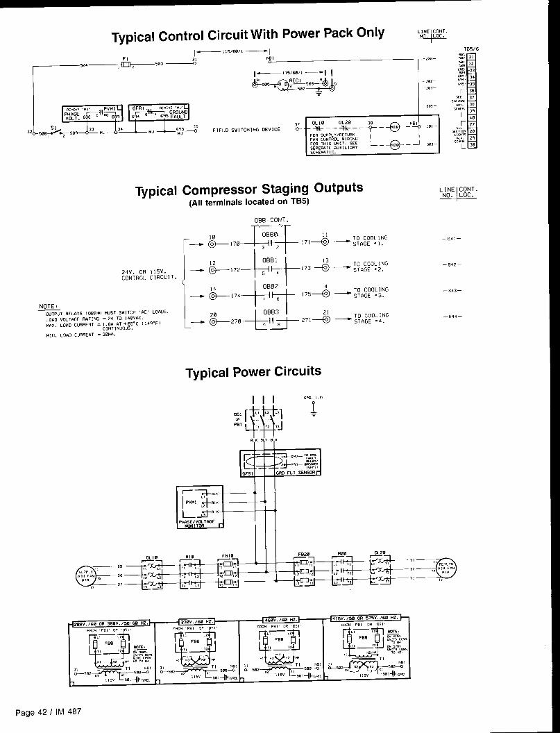
Typical Control Circuit With Power Pack Only .,. ~,,,.LINE CONT.
—115/6w1 —1FI NB 1
504 ~w~
–2i?–
,2
Typical
24V. OR 115V.CONTROL CIRCUIT.
NOTESOUTPUT RELAYS [ OBB*) HUS1 SNITCH 6C’ LOI$Ds.LOAD VOL1@3ER12T1NG = 24 TO 140vfiC.
)!hx. LO&D CURRENT = 1.80 OT +65-C 114q”F)CONT 1 NUOUS .
H,N. Lor10 CURRENT = 3BIUI.
cl=SUPPLY“ 2’“y, p ,2 2’
2,,,
I–m-
OLIO‘+-’”’-+–– OG––+–*–
FOR SUPPIY/RETURNFIIN CONTROL wIRING
IFOR THIS UNIT. SEE L_*– J–303-sEPER12TE FWX 1L !WiYSCHEMATIC.
Compressor Staging Outputs(All terminals located on TB5)
‘-
OBB-CONT.
OBBO
;:::f~
11171+ —
TO COOLING
32 sT14GE ●I.
OBB1
\:E:+$:::
Typical Power Circuits
1110 Gmw,
–B41–
—842—
—843—
—044—
page 42 I IM

Typical Main Control Circuit (VAV Units)—!!5/w/l —
F1
—504 503+---%WI –zwe—
—a2–
—2a–
–2m–
–2n —
-m7—
– a7—
-20—
-218–
–,, ,—
–2,2–
–2!, –
-,,4—
-2,5—
—2!G–
–217–
—2,*–
–2,. –
—2,, –
—22, -
–2,2–
–*23–
–224–
-2,5 —
–226–
–2,7–
-228–
-,2, –
–23B–
—23, —
ACT I(SW,
186
SE 1
,S2 1Slmlw
WCC em. 1I
t-)):; 345.
701 703 705
J+kl-11
702 704 706
,23579. .$1
I
PA+
Lm ‘[ WTWT
“d
“O’k!Il - ( WTWT~. FC+! CCGirm s m. M.“,x, .7U, ,7W I03c4.TO (+, -l m
W:%kl
.CAUIICNOmm, ,0
I“,CRWKC”1,., 6LUE1]mum.!%- L.X%
–236–
–237—
–25—
–F, —
- z53-
–a4—
–25–
–z5–
–x7–
- 25–
-z5—
-26—
-26—
-264—
- 26S–
-2T, —
-x7—
-268 –
-27a–
-27,—
-27. —
-275—
- 27s—
-277–
-27a–
-,79—
xe—
-ml–
a2–
– 24 VWTS n.C. FRG+I TRAJ&F. (T2) —A
IM 487 I Page 43
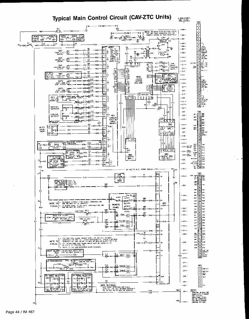
Typical Main Control Circuit (CAV-ZTC Units) ,Jl,l:%:.TB5
1—!!5 /60/1 —1
2n%–
w2-
203-
2e–
x6–
x7–
208-
2n—
.2, n–
-2!l -
-212-
-213–
-2,4—
-2,5–
.,t6—
-2!7–
-2 Le-
.2,.-
,2e—
-22, -
-222–
-223-
-22*–
-225-
-,26—
-227-
228–
229–
230–
-231-
r32 508
“T frf-55’ :: :,..,,,., .,. 554+1:!?
‘“’3E a— — &569 5 ;6“,,,. ZU4E
,Ew. S,*OR — — _&.?z-5,, , J
1111111111
L— m
-232-
-236 —
-,37—
-zl -
-x4–
– z,—
-25–
- ?Y—
-z2—
–x3-
–x. -
-x5—
—26—
–x7-
- 2,8—
-270–
—27. -
– 275—
I
-,7&—
–277-
– 27B–
—27,–
—2e@-
—28, —
– 2$2-
—zTJ—
—2,a—
I
— 24 WITS a.C. FR~ TRANSF. IT21 ~ ‘?
0
N
I48
1
, 10 WIA6LE [“lcRUW T1- CLCtK. TE8i4!N4Ls ,01KITE TO m ,82 !4”S1 NOT 8E -ERED.
FIELQ, 2. IF REMOTE PANEL [S W, uSEO. TEF?!1”AL5 !8>.lffi543 m, ,,, ““S1 ,S .41WERE0
~6 ,Fm.,,LTER)
543
—
—
II III n,4,L7.3*2,,RN -?44-?44
I
.—— A ‘“1749A+ 010
~ -72’P7”-,,1’‘ ;.@;~ NOTE 10 FIELD.7’2+L
x. ,;.:~:~,bn~. S“0(, CCTECTCMS oRE F,ELOSJ,,-L, EO, ,tf <“,, EWEEN lEMINALS
“*N mr C9W, E0. mm NOT .F?LIEO. .,, .53 $+40 .53 .5. “!s, w Rwwm. 7387,.
1. .
h
Page 44 I IM 487

Typical Main Control Circuit (CAV-DTC Units)‘- ,..
[— I1503W1 —1
—20–
– x2–
—m, —
–x5–
-2aG—
–x7–
–2’a–
–2a–
—2!a–
-2, ,-
–2,2—
–>,3—
–2,4—
–,,5–
–,,6—
–2,7–
–,,8—
–2,9—
–22a–
–221–
–222–
–223–
-224—
- ,,5—
- >26—
-227–
-228–
- 229—
-238 –
-231–
232—
H=... .“.
BRD .250 )
w+--!.cwTI’w!
mm, mH, CROTKH
{ 4H, wcc mm,,, ,NW,, @26 ,69 ‘: ,EXTERNAL — — — —
,... sm.,,,. , g:y,
WLLc7,NI — ‘mA”— +#-670
m AD I03.,,..,% G ‘ , mk?,LOGMmm .C0P5 “,,,, ,., ,
1., . ‘i~Pur-
i-
.,0 BOARD I., ,
Tx,;,+L( C%$UT
“l
– 24 VOLTS A.C. FROM TR’wJSF. ( 12) —1.4
7,
,?
1
18
5
5
!1,
P
21
—
z,,—
-2,7—
-2$–
-z4—
256–
-xe–
25—
-26—
-x,—
-26–
,65—
,,, —
2,7—
.26—
278–
272–
.27. —
275—
z,6–
277–
278-
27,—
2se—
2a—
282—
1.
101
-548
Y,33____+j_535Lz.53+Jq [(
k$5*-~–––-~537 !0,
, ma Com FAIL mm”. FmtwE “,,-!, .,W am ,.,, x,”,,”
N07, ml 7,,.,..,s .7, nNn .71. F,UO ,.srFiLEo ..C. CWTKT, BETKCN,,,”,..,s .5, M. .7, m .7, .“,, K OK. ON *MC” COB,,,, ON. ‘3’*’37f10’ i
36 N
IM 487 I Page 45
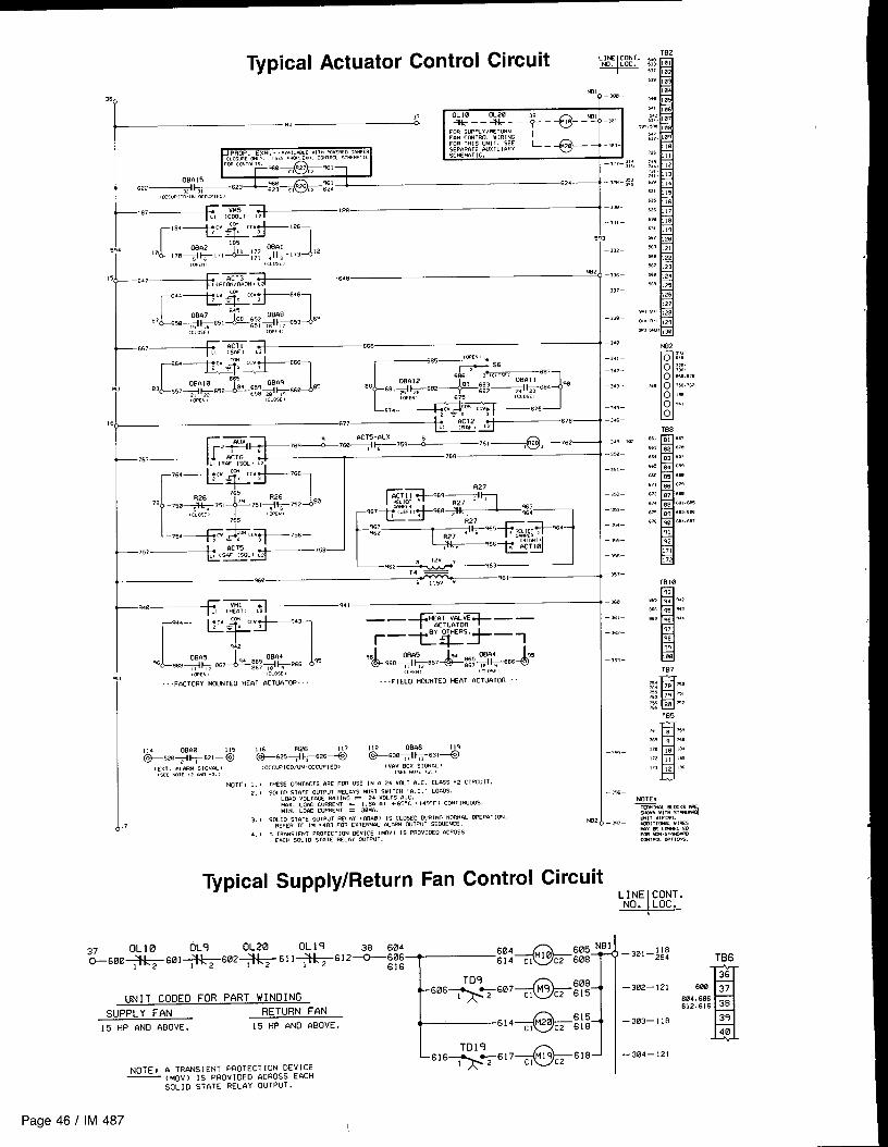
Typical Actuator Control Circuit
‘E& ‘-ePROP. EXH. -. ,val,ac W(1H ,ow=e,O Da”pEa
r‘a7~-~ ‘“
I “4-E”m&-’86,,,’5:,,,&1729’ 1 5
5,4 ,a
L
,7, , *[73 12
, :.,.’,
15
“7--IZ-0.Z(CL”F’ ‘“’
)62
“~’ ii-Ai ’78—
r7’4+l”@2+76’l
+------ ~ “-‘“=” ‘“
~“zy~]. “’~::j?g:i,0.,. , {cm<, ) ,0.,.,
“,
, ,,05! ,
-FoCTORY MOUNTED HEAT 6CTUATOR - -.-- .FIELO MOUNTED HE8T 4CTUaT0R -
INOTE, 1. ) TI+ESS CONTACTS AFIE FOR USE [N . 24 VOLT 6.C. CLASS ‘2 CIRCUIT.
2. ) SOLID STaTE OUTPIIT !+=1 r3YS ..S1 SWITCH ,0. C. LOADS.LOAD VOL lMX.,x, Lam CUR“[N, L06D CUR
3. B SOL 10 57’2TE OUTPI,7 .,,.. ,. ,“ .4,
4.) . .Ec,c” yx ,0 Si. fi ii.” OUTPUT.
;.T !-Nt = 24 vOLTS 9. C.RRENT = 1.80 S3T +65. C ( 14,-F I CONTINUOUS.RRENT = 38.,,
,“T ~LhY ( 06681 IS CLOSCO DURING NORM*L 0PER6T ION.. . 133 FOR ExKmm .LnR. cmpur 5EOUEKE.
\ a ,..,,.! .;,” ..”,,,,10. DEVICE ( !40” ) IS PROVIDED ‘ACROSS
Supply/Return Fan Control
-,m–
-33, –
-322–
-,3, –
–,37–
- ,M–
- 34a–
-,4)–
- >42–
-,4,–
- ,4,—
- ,4,–
- 3.9– m2
-3%–
- ,5t –
– 352 –
–3,, –
– 35. –
– ,55 –
–,%–
– ,57–
–,m–
–3,)-
– 3.5, –
– ,,3–
–,*–
UNIT COOED FOR PART WINDING
~ZZg’O]
cl C2 615
SUPPLY FAN RETURN FAN
15 HP AND ABOVE. 15 HP ANO ABOVE.M20
615cl C2 618
~lM19c2 618
NOTE I s TRANSIENT I’RoTEcTloN oEv IcE— (!40v) IS PROVIOEO aCROSS EACH
SOL]O sTRTE RELAY OUTpUT.
—302—121
—303—118
—304—121
TB6
1
36600 37
604.606612.S16 38
39
40
Page 46 I IM 487
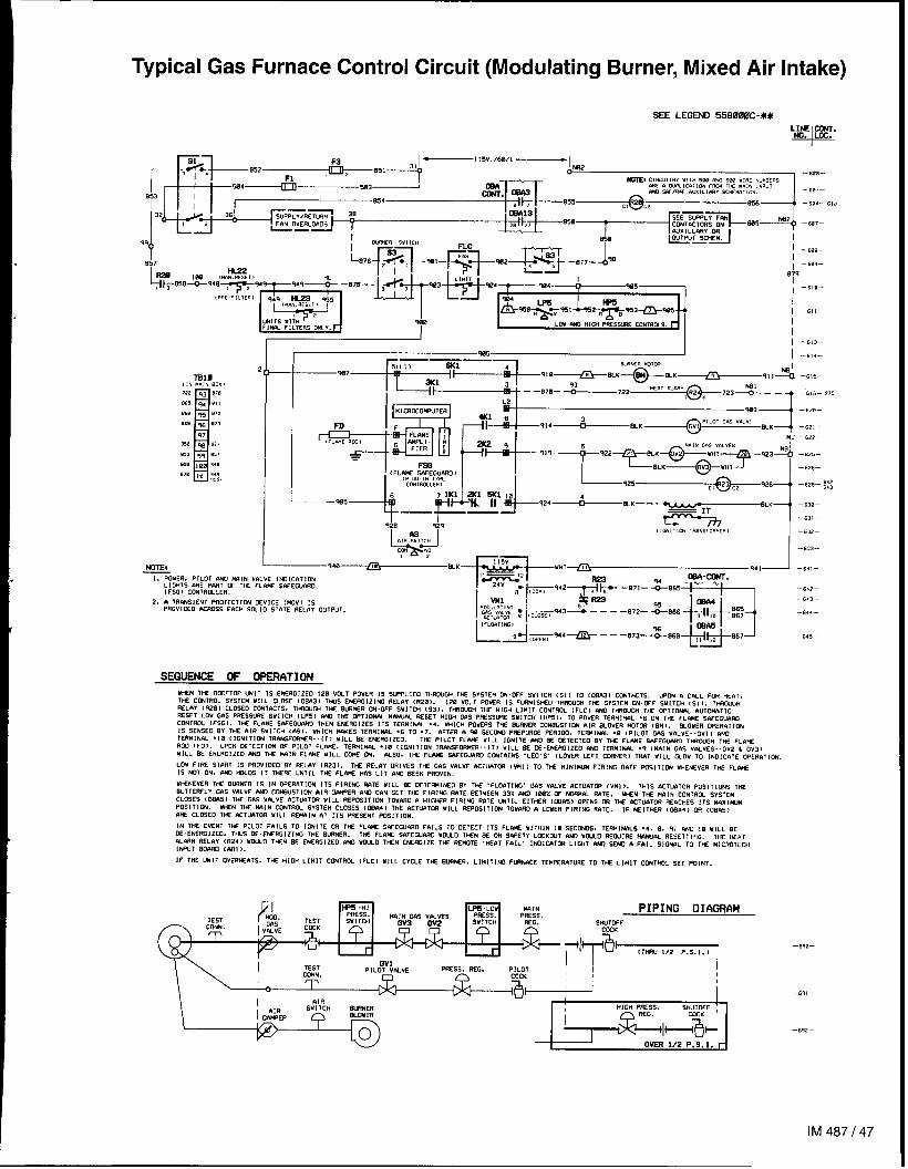
Typical Gas Furnace Control Circuit (Modulating Burner, Mixed Air Intake)
I I I -613–
.~ I -,,4-
A +?
L-#AsA,, ,“,,,,
co” m!?
NoTEl 940 /iEJ &K—
!. POWER. PILOT IWO M61N VhLVE lNOICATl ONL 1GHIS ORE PN?T W Thf FLCi!!E SAWW4SD1FSG I CONIRGLLER,
2. A lRfiNS!ENT FROTEC11C+4 DEvICE IMOV] 1SPROVI DEO ,USOSS EACH 30L ID STATE RELAY OUTPUT.
SEQUENCE OF OPERATION
-6,5-
–,,6–.975
—6,, -
– 6.,2—
–63, –
-63, –
( ,m, , ,CN TPms;mim,
I–,3?–-,,3-
W+EN WE RC93F1W WIT 1s ENERolzfO 120 Vul POWER 1s SWPLIEO THRWJ3H lK$ SYSTEM ~.WF WITCH (s1 3 TO toEn31 CCUIKTS. wmi R cm_L FOR HEAT,
TIE CONTROL SYSTEM WILL CLOSE [0Bf131 TWS E% RGIZING REL#i (RZB). 130 VOLT POUER IS FLWN1514E0 1HRCW3H THE SYSTEM C+-WF SWITCH (S11. 1-MLfiV (R28) CLOSED CWIACTS. TW(OuW TuE W?WR W. OFF SWITCH (S31. lFMOffiH TliE HIW LIMIT CCUTRfJL lFLC) MICl THSWW THE WT1ON& WTOM& TICRESET LO” C4S PRESSM S“[ lCH 1LP51 W T= WT1~ H#S(lW SE3ET HIGi GAS PRESSURE SV! lCH [ l+%,, TO POWER TERM!wL .6 ON THE FLti 3PfEGUAWl
Ccwlful. lFSGI. THE FLhNE s.wEGwAll THEN EWRGIZES 11s TERMIwL .4, WHICH POWERS 1S 2wNER CC4!+WSTION IIIR BJWER MOTCFI (w,. EIOUER CPEIWTU2N
Is SEs5m W THE nlR WITCH cASI. WHICH #AKES TERMINAL .6 TO .7. hFTER & % WC~ PREP”RGE PER1OO. lESMI)klL .E (PILOT WS V61LVE. .GVI ) A&U
TEWINAL .10 (IONIT]W TRwSFCZ=WER-.111 WILL 2E EMFRGIZEO. Tw p] LOT FLIWS UlLL IWITE mm ~ 027 ECTE0 w 1* FL.wE 3wEwm wwur,n THE FLWtRCO IFD1. UPON ~TEc1!G+4 W PILOT FL%. TER!41?4,% .18 ttGN1ll ON TRANSFC#lMCR. .IT1 WILL BE 13 E. EMERGIZEO f#4Q lER”l NAL .q (FAIN GhS VALVES.. GV2 & Gv3>
MILL 3t ENERc12E0 nuo Tw MIN FLW WILL co% w WSO. WE FL~ SWEWa~ CUiThlffi .LEO.5. (LOWER LEFT CL!+7NER, TMT WILL WOW 10 !NDICATE CWRfiTICti
LOU FIRE START 1S PSWIOEO W REL.IY 1R23). THE REL12Y ORIVES THE GsW VALV2 6CT14?T~ (WI 1 TO T* ❑ INIMUM FIRlffi RATE FUSIT!CN MHENSVER THE FL#VE
[S NOT ON. M ~D5 IT TwERE UNIIL lHE FLA)lE HIW LIT 6$93 BEEN PSOVEN.
U~NEVER THE w$WR IS IN OPERATION ITS F! R1ffi RATE U(LL BE CE1EG141WD W THE .FLOfiTl M7. GAS V#LVE hCTUnTCSi (W! 1. lHIS ACT~TOR PoSITIONS THEuullEsfLy cns VfiLVE w Cw5710N AIR WIPER nm cnN SET T= FIRING MIE i7E7wEN 33% M wiw w NC+IMOL RaTE. ww 7~ n,a IN CONTROL SYSTEM
CLrlSES (CW5) W+ GfiS V,%VE ACTLkaTOR WILL REPOSITION TOW,SD a HI(WER FIRlffi WTE lMTIL EITHER (~h5) OPENS LM THE AC1U9TOR RERCHES 11S WXIW+!
Pffil TlC?4. W2N THE IWIN CCNTR~ SYSTEM CLOSES (C%A4) WE MTu.4T~ “ILL REPOSITION 10W,RD t! LOVER FIRING RIITE. 16 WI TtilR (LMh4) OR ,0 Bfi5)
4SE CL03E0 TtBZ ACTUATOR MILL REIMIN 6? ITS ME3ENT POS!T! ON.
IN T* EvEN7 TM PILOT FAILS To !GNITE m T* FL* sh=cGunRo FarLS TO OETECT !7s FLfis WITHIN Ia SECMS, TERHIMLS .4. 0. q. ~ ,0 “,LL ~
N. ENERGIZEO. 1w2 %. EWRGI ZING 1* 8WR. THE FLRW SAFEW~ MW-O lWN SE W S,WETY LOC103LlT A)4D MW10 REWIRE M6Wm RESETT 1,,G, TW W*T
nLA7H sww tR248 mu-o T*N x ENER012E0 ern wcuo T*N E* SGIZE T* REW3TE .*fiT FAIL. lPiOt cATOR LIGHT aso SEW n Fnt L SIGWL TO T* Ml CR07ECH
[M=(JT SLwin cm]).
IF 1H2 WIT OVER~&TS. THE H!DH LIMIT CWIROL (FLC1 WILL CYCLE Thl 8L!WEFI, LIMIT Iffi F12wACE TE”mw,”RE TO TW L,”, T cWTRW SET PO, NT.
ys~~ MAIN PIPING DIAGRAMTEST
PsEss.SWITCH REG. WTDFF
CEK
a, -a~+1
“~~ESS. SEG. P!L0TCOCK
& iLOv W
W] lCH M_Si?4ER HIGH PRESS. S;U&l ;
I~lH@
I OkER1/2 P,S. I. r
—6.2—
–643–
—644-
-645–
—8,,–
-s,2–
IM487147
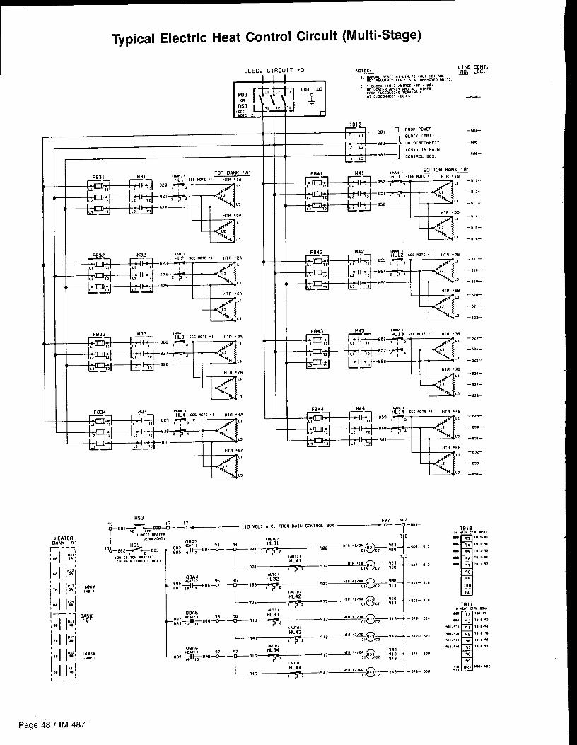
Typical Electric Heat Control Circuit (Multi-Stage)
ELEC. C
FB32 M32 (M. I
w LI
L2
L3
FB41 M41 (w. ! BOTIOH BANK ‘ B“
TICILb
,2
1.>
FB42 )442 ,*N I
m LI
,2
L]
FB43 M43 (w. !
FB44 H44 ,*, I
w Ll
,2
,1
170BA4
(w,, rq5 ~a6 HL32
m353&e6& _007 ,, 7
E
%!7
5 :/
“18 “2”:, 32 C2 :: –864- 81812
,ml,.)t4L42
936 q37 *TR ‘2”;, 42 ~2 ;:; -566— 51atz
oBA5,Wlol
qs HL338’673&8& — 911 , ~
E
912 “ln “3<’;, 33 ~z 913 -WI- UZ4
809 !2 ,1,NnolHL43
941 942 n“ “’”:, 43 ~z q43 -B72- 524,2
08A6IWO,
*.,.4 97 HL34 903
E
e8?~l#W~ — 916 ,- -2q17 “n ““e;, 34 ~2 q18 -574- ~~9
q48(Ml, !
HL44
=?46 q47 “m “’”;, 44,2 940 -s,,- 33912
-t.,,--012-
-813-
-,,4—
-stc.-
-81c-
-,,,-
-818—
-s,!-
- 82@-
-62!-
-522-
- Bzl-
-824-
- sm-
- 82a—
- 5z7-
-021-
- s29-
- s3a-
-81t —
- 8Y2-
- .331—
- n34-
Page 48 I IM 487

Unit Options
Enthalpy
Outside Air Enthalpy Control (OAE)Units with an economizer come standard with an electro-mechanical enthalpy control device (OAE) which senses boththe humidity and temperature of the outside air entering the
unit. This device has an enthalpy scale marked A through D,Table 10 shows the control points at 50% .RH for settings A
through D, Figure 35 shows this scale on a psychometric
chart. When the outside air conditions exceed the setting ofthe device, the outside air dampers are positioned to the mini-mum outside air intake position by the MicroTech controller.
Table 10. Errthalpy Control Settings
~
Control Point 0F ( oC) at 50% RH
Differential Enthalpy Control (OAEIRAE)An optional electronic differential enthalpy control arrange-ment (OAE/RAE) is available. In this configuration a solid-statehumidity and temperature sensing device is located in boththe return (RAE) and outside intake (OAE) airstreams. ThisOAE device has the same A through D scale as the devicedescribed above. However, with the OAEIRAE arrangementthe switch on OAE must be set all the way past the “D” set-ting. With this done, the MicroTech controller will adjust thereturn and outside air dampers to use the airstream with thelowest enthalpy.
Control
Figure 35. Enthalpy Control Settings
Part Winding Start
The part winding” start option is used to reduce the locked Figure 36. Part Winding Startrotor inrush current of the fan motors (208/230 volt units).
The motor has dual windings which are energized with dualcontractors. The first contactor closes, energizing one winding.A time delay relay closes the second contactor about one se- 4)
cond later, energizing the second winding and bringing the TD9
motor up to full speed. Figure 36 is a typical wiring schematic r- .— Motor Contractors1
showing part winding start. IIL .— J
Ground Fault Protection
The ground fault protection is designed to protect motors from volt control circuit to shut the unit down whenever a grounddestructive arcing ground faults. The system consists of a fault condition exists, The ground fault relay is self powered,ground fault relay and a ground fault current sensor. The The ground fault sensor is a current transformer type of deviceground fault relay employs solid state circuits that will in- Iocated at the load side of the power block through which thestanteously trip and open a set of relay contacts in the 115 power wires of all phases are run.
Phase Voltage Monitor
The phase voltage monitor protects against phase loss (single when all phase voltages are within specified limits. The phasephasing) when any one of three line voltages drop to 74% voltage monitor is located on the load side of the power blockor less of setting. This device also protects against phase with a set of contacts wired to the 115 volt control circuit toreversal when improper phase sequence is applied to equip- shut the unit down whenever the phase voltages are outsidement, and low voltage (brownout) when all three line voltages the specified limits.drop to 90%0 or less of setting. An indicator run light is “on”
IM 487 I Page 49

Optional Remote Monitoring and Control Panel
One to eight applied rooftop units can be incorporated into Figure 37. Remote Monitoring and Control Panela network with” the MicroTech Remote Monitoring and Con-trol (RMC) Panel. The optional RMC Panel provides the follow-ing keypad programmable features:. Remote unit monitoring (up to eight). Common duct static pressure and heat/cool changeover
control of multiple VAV units (groups of two to eight). Common zone temperature control of multiple CAV units
(groups of two to eight)● Optimal start control of each unit. Common unit schedulingFor further information refer to Bulletin No. IM 444, “MicroTechRemote Monitoring and Control Panel.”
Remote Monitor Panel
The optional Remote Monitor Panel provides remote indicatorlights and fan on-off and system heat-auto-cool switches. Referto Figure 38.
Wiring should be sized in accordance with Table 11 andconnected to the panel terminals in accordance with the unitwiring diagram. The panel can be mounted on a standard 4x4junction box.
If the Remote Monitor Panel is not used, terminals 101 and105 must be jumpered to enable cooling, and terminals 101and 106 must be jumpered to enable heating. The fan is en-abled when either cooling or heating is enabled.
Table 11. Low Voltage Field Wiring
~
“Maximum wire length is based on a voltage drop of 2 volts
External
An external time clock can be used as an alternative to (orin addition to) the MicroTech controller’s internal schedulingfunction. The external timing mechanism is set up to openand close the circuit between field terminals 101 and 102.When the circuit is open, power is not supplied to digital in-put DI (terminal DHI-1) on the ADI board. This is the normalcondition in which the programmable internal schedule is
Smoke
Optional smoke detectors can be located at the supply andreturn openings. The wiring schematic for these smoke detec-tors is shown on any of the “Typical Main Control Circuit”schematics in the “Wiring Diagrams” section of this manual.
The sequence of operation for these detectors is as follows:When smoke is detected by either sensor, the normally closedsensor contacts open. This removes power from digital inputDll (terminal DH2-11) on the ADI board. The MicroTech con-troller responds by shutting the unit down. The controller
Micmlecil!ap@ed Fu3dtoP
Figure 38. Optional Remote Monitor Panel
HEATAUTO
;Ooi R
ONOFF B
L
•1•1•1•1
I I
II
Time Clock
followed, When the circuit is closed, power is fed to DH1-1.The MicroTech controller responds by placing the unit in theoccupied mode, overriding any set internal schedule.
For more information, see the “Digital Inputs” section ofBulletin No. IM 483, “MicroTech Applied Rooftop Unit Con-troller.”
Detectors
is placed in the Alarm Off state, and cannot be restarted untilthe alarm is manually cleared. Refer to the operation manualsupplied with the unit for information on clearing alarms (seeTable 1).
The smoke detectors themselves must be manually resetonce they have tripped. A reset button is provided on the frontface of the smoke detector (refer to Figure 6 for smoke detectorlocations).
Freeze Protection
An optional freezestat is available on any unit that has hot and closes, the MicroTech controller will take different action,water or steam heating coils. The sensing element is located depending on whether the fans are on or off. The freezestat is anon the downstream side of the heating coil in the heating sec- auto reset type of control; however, the controller alarm it causestion of the unit, If the freezestat detects a freezing condition is manual reset if the fan is on and auto reset if the fan is off.
Page 50 I IM 487

Fan On Operation Fan Off Operation
If the freezestat detects a freezing condition while the fan is If the freezestat detects a freezing condition while the fan ison, the MicroTech controller will shutdown the fans, close the off, the MicroTech controller will open the heating valve andoutdoor air dampers, open the heating valve and cooling cooling valve, and set a 10-minute timer. The MicroTechvalve, and set a 10-minute timer. The MicroTech controller’s controller’s current alarm (menu 29) will be “Freeze Stat Prob.”current alarm (menu 29) will be “Freeze Stat Fail.” When the 10-minute timer expires, the controller begins
When the 10-minute timer expires, the controller begins checking the freezestat again. If the freezestat is open, thechecking the freezestat again. If the freezestat is open, the heating and cooling valves will close. If the freezestat closesheating and cooling valves will close. If the freezestat closes again, the heating and cooling valves will open, and the 10-again, the heating and cooling valves will open, and the 10- minute timer will reset.minute timer will reset. When the freezestat opens again, the “Freeze Stat Prob
The unit will remain shut down until the “Freeze Stat Fail” alarm automatically clears. This feature protects the coil andalarm is manually cleared. Refer to the operation manual sup- allows the system to start normally after a cold night.plied with the unit for information on clearing alarms (see Table 1).
Duct High Pressure Limit
The duct high pressure limit control (DHL) is provided on all scale showing the current setting. Turning the adjustmentVAV units, including the CAV-DTC unit that can be field con- screw located on the bottom of the device adjusts the settingverted to VAV. The DHL protects the ductwork, the terminal up or down.boxes, and the unit from overpressurization which could be If the DHL switch opens, digital input D7 (terminal DH1-7)caused by, for example, tripped fire dampers or control failure, on the ADI board will be de-energized. The MicroTech con-
The DHL control is factory set to open when the discharge troller then shuts down the unit and enters the Off-Alarm state,plenum pressure rises to 3,5” WC, (872 Pa), This setting The alarm must be manually cleared before the unit can startshould be correct for most applications; however, it is ad- again, Refer to the operation manual supplied with your unitjustable. Removing the front cover of the device reveals a for more information on clearing alarms (see Table 1).
Variable Inlet Vanes
Variable inlet vanes are installed on the supply and return fansof VAV units. They are also installed on the return fans of con-stant volume units that have direct building static pressurecontrol capability.
The inlet vane assemblies consist of airfoil type inlet funnelswith integral sets of lever-actuated radial vanes. DWDI housedsupply fans have one assembly on each side of the fan. Re-turn fans, as well as units with SWSI plenum supply fans, haveone assembly on the inlet side of the fan only, When theyopen, the inlet vanes direct air in the direction of wheelrotation.
The vanes are able to rotate 90° from full closed to full open.A stop limits the amount of travel open and must not bechanged. Driving the vanes past this stop will cause the vanehub cam linkage to disengage. The vanes will turn indepen-dently of each other, and the hub assembly will have to be over-hauled. The moving parts of the vanes are permanently lubri-cated. All threaded fasteners must be periodically checkedfor tightness.
All airfoil fans with inlet vanes are provided without motoractuators for field control installation, or maybe shipped fromthe factory with complete linkage and actuator assemblies.Field installed linkages and actuators would be connected atPoint B on Figures 39, 40, and 41,
Minimum Vane PositionOperation with the inlet vanes closed completely may resultin fan pulsation and excessive vibration. In units equippedwith MicroTech controls, the vanes are automatically openedapproximately 5 degrees by the control system prior to fanstart-up. Field installed linkages and actuators should bepreset to close to no less than 5 degrees open.
DWDI Housed Supply Fan Vane AdjustmentFigure 39 shows the supply fan vane linkage assembly. Bothsets of vanes on the supply fan must operate in unison, Ad-justments to the motor rod end and locknut (Point A) as wellas to the floating link ends (Point C) can be made to assureuniformity between the linkage assemblies.
The vane actuators must have 180-degree rotation. Do notmake linkage adjustments to compensate for improper ac-tuator rotation, but correct the actuator rotation adjustment.Refer to “Actuator Rotation Adjustment” on page 55. Note:There are two difference actuator rotation configurations.These are shown as View 1 and View 2 in Figure 39. Referto Table 12 below to determine which view applies to a par-ticular unit,
On units with vane controls on both the supply and returnfan, it is important that both actuators have exactly 180-degreerotation to assure proper “tracking” of the two actuators.
Table 12. Applicable Actuator Linkage Configurations
Supply Fan “z”Motor
Figure 39
Wheel Size (Refer to ReferenceHP
in Inches (mm) Figure 39) View
27 38.1 (988mm) 5—40 2
30 42.3 (1074 mm) 5–40 2
33 464 (l179mm) 5—40 2
36 51.5 (1308 mm) 5—40 2
36 51.5 (1308 mm) 50—60 1
40 56.8 (1443 mm) 15—40 2
40 58.8 (1443 mm) 50–75 1
I Inlet vanes must not be adjusted to close tight during fanoperation.
I A minimum operating position of 5 degrees open is recoin.mended to avoid pulsation,
Units with factory installed MicroTech controls will automaticallyopen vanes 5 degrees prior to start-up.
IM 487 I Page 51

Figure 39. DWDI Housed Supply Fan Vane Assembly-~aczos
“B”(BOTH SIDES)
/- —----
\
‘\ADJUSTABLE
(I v,’ [za~m] SLOTJ
‘\
, / ‘FLOATING -.
// “:\#/ *
VIEW#l, -’-—--\,\
/’~k ---. \
\ --,/-” —--,/“ OPEN .- \ /
ml-l ‘\/ ‘\
VIFW #2 /’ . ‘\ /’
d I-HI-i
-/’—--
\
\
I
I
I
i
/
\~ CLOSE~/ ‘
\ /------- Y&?%,,
Plug Supply Fan Vane AdjustmentRefer to Figure 40a for 40” wheels, Figure 40b for 44” wheels, As the actuator moves from Odegrees to 180 degrees, the
and Figure 40c for 49” wheels. The vane actuator must have vanes should move from O degrees (closed) to 90 degrees
180-degree rotation. Do not make vane adjustments to com- (full open). This can be adjusted by changing the linkage rod
pensate for improper rotation, but correct the actuator rota- Iength by loosening the nut and sliding the rod at Point A or
tion adjustment. (Refer to “Actuator Rotation Adjustment” on Point B and retightening the nut.
page 55.)
Figure 40a. Supply Fan Assembly (40” Wheels)
-=-—.,/” . .
\/’ . .
\/’
/’1’
i
/ 18”
i~
‘\ Ar- 1
‘/ /’
-“/
“.
\ /’‘.\ /’-. ,.
=.. /—— --
Page 52 I IM 487
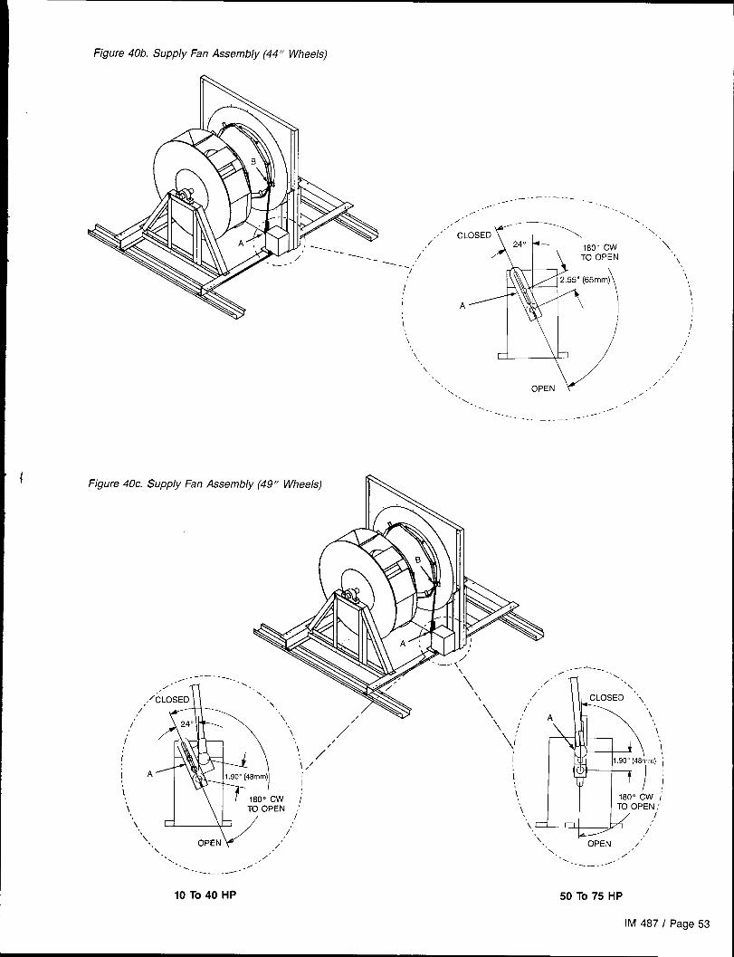
Figure 40b. Supply Fan Assembly (44” Wheels)
““ CL‘\
/’Cw “\
/’ PEN ‘.--- ../ \
/
\
‘,
m)\
i
\i
i A I
\/’ i
./ ---- -..,. . ../’
/’~..
-~\
. ,-
‘\ w /’~.\ .. OPEN
/’\
,,/. .
=.. /“. . ,.-
. . ./-----— .. _.. _ ----
Figure 40c. Supply Fan Assembly (49” Wheels) IN
.. ——-.. \\\\\\ 7//
‘,
‘ +,[ 180” CW i
\ TO OPEN ‘‘. i\
‘. /’\
. . OPEN\
/’..\ ,/’
. . ,<
“\\ , ‘ ‘‘\\ /“ \
i,; \i
I m) i
II
‘1
“’Q-=14’7‘. OPEN ,/’
\. . /’,. .,
-— ---. . ----—----
10 To 40 HP 50 To 75 HP
IM 487 I Page 53

Return Fan Vane AdjustmentRefer to Figure 41a for 40” wheels; Figure 41b for 44” wheels.The vane actuator must have 180-degree rotation. Do notmake linkage adjustments to compensate for improper rota-tion, but correct the actuator rotation adjustment. (Refer to“Actuator Rotation Adjustment” on page 55.)
Figure 41a. Return Fan Vane Assembly (40” Wheel)
/
y
A
As the actuator crankarm rotates from O degrees to 180degrees, the vanes should move from O degree (closed) to90 degrees (full open). This can be adjusted by changing thelinkage rod length by loosening the nut and sliding the rodat Point A or Point B and retightening the nut.
/’
[‘m-‘1\i
[ ‘- ‘-1—.—-——-
CLOSED OPEN ,/’i /‘\ 2,30”
.- /’
‘\ (58mm) 0’“\ ./”
VIEW A-A
‘-.- /“0-
--. —.-.
Figure 41b. Return Fan Vane Assembly (44” Wheel)
.\‘\
.\.\.
\B.Z ------ --.<.
/ -.% .\
[
180” Cw
/.----- -.
.\.TO OPEN.-
.0. \- ./ \/ \. ./ .\
i\. ! \
d >% 1’
\ 1“ .\i .\i ~18”
“\‘\ i
i i i“\ ;
.\i i
;.\ “\ 1“
.\.\ “<. /.’
0.2.65” (67m’m)
.x. ----------. s -. #.
-------- .
Page 54 I IM 487

Actuator Rotation Adjustment lock on the shaft side and engaging the screwdriver blade
The counterclockwise (as viewed from shaft end of actuator) with the edge of the notched cam nearest the front of the ac-
Iimit switch is adjustable on the Barber-Colman actuator. The tuator. Turning the cam clockwise (as viewed from the shaft)
clockwise limit is not adjustable. The CCW limit setting can increases the amount of actuator rotation. Each click of the
be changed in the field by inserting a screwdriver through cam represents about a 3 degree change in actuator rotation,
the opening in the top plate directly ahead of the terminal The actuator should be set for 180 degrees rotation.
Convenience Receptacle/Section Lights
A convenience receptacle is provided in the main control boxon all units. To utilize this receptacle, a separate field sup-plied 115V power wiring circuit must be connected to the 115Vfield terminal block TB1, located in the main control box. Notethat the National Electrical Code requires that this circuit beprotected by a ground fault circuit interrupter (GFI) device.
Optional lights are available for certain sections in the unit.Each light includes a switch and convenience receptacle, and
Typical Field Wiring for Lights and Receptacle
&
~ Field Supplied 115VAC ~
4BLK
+-
LT WHT
BLK >~BLK~WHT775 + 9 . . 4
TBI. -is powered by the external 115V power supply connected to
‘775+77’A
Check, Test, and Start Procedures
Electric shock and moving machinery hazard. Can cause severe equipment damage, personal injury, or death.
All start-up and service work must be performed by qualified technicians who are familiar with the hazards of working on this type ofequipment.
Do not attempt to operate or service this equipment without first reading and understanding this manual, the “MicroTech Applied Roof-top Unit Controller” manual (Bulletin No. IM 483), and the applicable operation manual (Bulletin No. OM 108, OM 109, or OM 110).
Assure that the frame of the equipment is bonded to the building electrical ground by use of the grounding terminal or by other accept-able means,
Disconnect electrical power before servicing this equipment.
All units are completely run tested at the factory to assureproper operation in the field. Nevertheless, the followingcheck, test, and start procedures must be performed to pro-perly start the unit. To obtain full warranty coverage, the check,test, and start form supplied with the unit must be completed,
1.
2.
3.
4.
5.
BeforeVerify that the unit is completely and properly installedwith ductwork connected. Verify that all constructiondebris is removed, and that the filters are clean.
Verify that all electrical work is complete and properly ter-minated. Verify that all electrical connections in the unitcontrol panel and that the proper voltage is connected.
Verify that gas piping is complete and leak tight. Verifythat the shutoff cock is installed ahead of the furnace,and that all air has been bled from the gas lines.
Manually rotate all fans and verify that they rotate freely.Verify that the belts are tight and the sheaves are aligned.
Check tightness of setscrews in bearings and fan wheel(s).If retightening is needed, make certain the fan wheel(s)are positioned per Table 16 and setscrews are torquedper Table 15. Caution: Equipment damage due to loosefasteners represents improper start-up and equipmentabuse. It is not covered by the warranty.
After First 48 Hours of Operation:a. Disconnect and lock electrical power source. Check
signed, and returned to McQuay International,A representative of the owner or the operator of the equip-
ment should be present during start-up to receive instructionsin the operation, care, and maintenance of the unit.
Start-up
6.
7.
8.
tightness of all bearing, wheel and sheave setscrews(or capscrews). Torque per Table 15.
b. Recheck all belt tension and adjust if necessary. Beltstensioned sufficiently to slip one to two seconds atstart-up will perform satisfactorily, extending life andreducing vibration. If retensioning is necessary, be cer-tain sheave alignment is retained.
Verify that the evaporator condensate drain is trapped,and that the drain pan is level.If unit is curb mounted, verify that the curb is properlyflashed to prevent water leakage.
Before attempting to operate the unit, review the controllayout description to become familiar with the controllocations.
Review the equipment and service literature, the se-quences of operation, and the wiring diagrams to becomefamiliar with the functions and purposes of the controlsand devices.
Determine which optional controls are included withthe unit.
IM 487 I Page 55
9. Before closing the power disconnect switch, open thefollowing unit control circuit switches:
a. Main Control Panel● Turn system switch S1 to “Off.” 11.c Electric heat units: Turn switch HS1 to “Off.”
b. Furnace Control Compartment● Turn furnace switch S3 to “Off.”
10. If the VAV or CAV-DTC unit does not have an optional zone
temperature sensor (ZNT1) connected to it, change theentry under keypad menu item 28 (“Space Sensor=”)from “Yes” to “No.”
If desired, all MicroTech internal control timers can bereduced to 20 seconds by changing the entry underkeypad menu item 28 (“Timers=”) from ‘(Normal” to“Fast.” This will reduce the delays associated with nor-mal control action for 15 minutes or until the entry ischanged back to “Normal.”
Power-up
1. Close the unit disconnect switches. to the MicroTech controller, and the LED’s on MCBI (red,green, and amber) should follow the normal start-up se-
2. Turn the S1 switch to “On. ” Power should now be supplied quence (refer to the “Component Data” section of IM 483).
Fan Start-up
1. If the unit is equipped with an optional Remote Monitor e. Trace the circuits.Panel, turn the on-off switch to ‘rOn," and turn the heat-auto-cool switch to “Auto.”
3. If the fans are equipped with optional spring isolators,check the fan spring mount adjustment. When the fans
2. If the RAH has controls, place the unit into the “Occ-Fan are running they should be level. Refer to “Spring IsolatedOnly” mode through keypad menu 11 (“Control Mode”). If Fans” in the “Preparing Unit for Operation” section ofthe RAH has no controls, check the fan rotation and con- this manual for information,tinue on to Step 3. The controller should enter the Start-up Initial operating state. After the Startup Initial timer
Note: The supply and return fan drives are usually selected
has expired (3 to 4 minutes), the fans should start. Ob-for operation in the drive’s midspeed range. The return fan
serve the fan rotation and, if it is backwards, disconnectdrives are usually shipped with fixed pitch sheaves that will
power and reverse two legs of the power supply.provide the selected fan speed; however, the supply fan drives
If a fan does not run, do the following:are usually shipped with variable pitch sheaves that are ad
a. Check the control circuit fuse (Fl).justed to provide the minimum fan speed. Both drives should
b. Verify that the overloads have not tripped.be adjusted for proper airflow during air balancing. For more
c. Check the fan motor power fuses.information, refer to “Air Balancing” near the end of this
section.d. Verify that the Remote”Monitor Panel wiring is correct
(if any).
Economizer Start-up
Improper adjustment may damage the dampers.
Assure proper damper adjustment. When an economizer isordered without an actuator, the linkage requires a 3.14-inch(80mm) linear stroke to fully open it. Do not allow dampersto be driven beyond their normal full closed or full openpositions.
1, Check whether the outdoor air is suitable for free cool-ing by displaying keypad menu 9. “Low” indicates lowoutdoor air enthalpy; “High” indicates high outdoor airenthalpy.
Referring to “Enthalpy Control” in the “Unit Options”section of this manual, verify that the enthalpy change-over control is working properly. You may want to taketemperature and humidity measurements.
2. At the keypad, set the cooling setpoints low enough sothat the controller will call for cooling. On CAV-ZTC units,adjust the “Cooling Spt =” entry on menu item 12. OnVAV or CAV-DTC units, adjust the “Cooling Spt =” entryon menu item 12 and the Setpoint=” entry on menuitem 13.
3.
4.
5.
Place the unit into the “OCC-COOIOnly” mode throughkeypad menu 11 (“Control Mode”).
Observe the outdoor air dampers.If the outdoor air enthalpy is low, the Step-and-Wait
algorithm should modulate the dampers open.If the outdoor air enthalpy is high, the dampers should
maintain their minimum position. Set the “Min Airflow=”entry on menu item 21 to some other value. Verify thatthe dampers move toward the new minimum positionsetpoint.
If the unit isequipped with the electromechanical en-- r
thalpy changeover control (Honeywell H205) and the out-door air is borderline, attempt to change its input to theMicroTech controller by turning the switch to “A” or “D”.Check menu 9. If the changeover occurred, go to step4 above.
Note: It may not be possible to check the economizeroperation in both low and high enthalpy states on the sameday. If this is the case, repeat this procedure on another daywhen the opposite outdoor air enthalpy conditions exist.
Page 56 I IM 487
Heating System Start-up
General1.
2.
3.
At the keypad, set the heating setpoints high enough sothat the controller will call for heating. On CAV-ZTC units,adjust the “Heating Spt =” entry on menu item 12. OnVAV or CAV-DTC units, adjust the “Heating Spt =” entryon menu item 12 and, if equipped with modulating heat,the “Setpoint =” entry on menu item 14.
Place the unit into the “Occ-Heat Only” mode throughkeypad menu 11 (“Control Mode”).
Verify that the high ambient heating lockout temperature,“Max OAT=” (menu item 14), is set above the’ outdoorair temperature.
Gas FurnaceRefer to the “Start-up and Operating Procedures” section ofthe forced draft gas fired furnace installation manual, BulletinNo. IM 484. Perform the start-up procedures given in it.
1.
2.
Electric HeatTurn the electric heater switch HSI to “On. ” The electricheaters should energize. If the unit has multistage electricheat, the MicroTech controller should energize the heaters insuccessive stages, The rate of staging is controlled by menuitem 14, “Stg Timer=” (default is 5 minutes).
Steam HeatThe steam valve actuator should open the valve. The steamvalve is open when the valve stem is up, If the unit loses power,the spring in the actuator should drive the valve wide open.Check this by opening system switch S1.
Hot Water HeatThe hot water valve actuator should open the valve to the coil.The three-way hot water valve is open to the coil when thevalve stem is down. If the unit loses power, the spring in theactuator should drive the valve wide open to the coil. Checkthis by opening system switch S1.
Cooling System Start-up
Place the unit into the “OCC-COOI Only” mode through 3. At the keypad, set the cooling setpoints low enough so thatkeypad menu 11 ((’Control Mode”). the controller will call for cooling. On CAV-ZTC units, ad-
Verify that the low ambient cooling lockout temperature,just the “Cooling Spt=” entry on menu item 12. On VAV
“Min OAT=” (menu item 13), is set below the outdoor airor CAV-DTC units, adjust the “Cooling Spt=” entry on
temperature.menu item 12 and the “Setpoint =” entry on menu item 13.
Adjusting MicroTech Controls andServicing Control Panel Components
Adjusting MicroTech ControlsIn order to read values, adjust setpoints, clear faults, etc., onthe MicroTech unit controller, the main unit control panel mustbe energized. If the unit has a factory mounted disconnectswitch, the switch’s bypass mechanism must be used in orderto open the main control panel door without de-energizingthe control panel. The bypass mechanism is activated by tur-ning the screw at the bottom of the disconnect switchclockwise while pulling the door open. Use of the disconnectswitch bypass mechanism must be done only by a qualifiedservice technician.
Electrical shock hazard. May cause severe injury or death.
Ail protective deadfront panels must be closed when makingadjustments to the MicroTech unit controller.
Whenever the main control panel is accessed with the con-trol panel still energized, the inner deadfront protective panelsmust remain closed to avoid exposure to high voltage power.
Servicing Control Panel Components
Hazardous voltage. May cause severe injury or death.
Disconnect electric power before servicing equipment, Morethan one disconnect may be required to de-energize the unit.
All electric power to the unit must be disconnected wheneverservicing control panel components located behind the pro-tective deadfront panels, The components behind the protec-tive deadfront panels are energized with high voltage unlesselectric power is disconnected to the unit. Units must alwaysbe inspected for multiple disconnects to ensure all power isremoved from the control panel and its components beforeservicing.
IM 487 I Page 57

Air Balancing
Moving machinery hazard. Can cause severe personal in-jury or death.
Use a strobe type tachometer to measure the speed of returnfans, Safety considerations prohibit the use of a mechanical-ly driven tachometer on this fan arrangement.
Air balancing should be performed by a qualified air balanc-ing technician. Note that the supply fan motors may be ship-ped with variable pitch sheaves which are typically set at thelow end of the drive’s fan rpm range. See “Mounting and Ad-justing Motor Sheaves” below for more information. The returnfan motors are usually shipped with fixed pitch sheaves.
The following should be performed as part of the air balanc-ing
1,
2.
3.
4.
5.
procedure:
Check the operating balance with the economizerdampers positioned for both full outdoor air and minimumoutdoor air.
Assure that the total airflow will never be less than thatrequired for operation of the electric heaters or gasfurnace.
For VAV units that have fan tracking control, adjust thesupply/return fan balance by using the MicroTech con-troller’s built-in, automatic capability. For complete infor-mation on using this feature, see the “Return Fan Airflow:Fan Tracking Method” section in Bulletin No. OM 108,“MicroTech Applied Rooftop Unit Controller: VAV Control.”
When the final drive adjustments or changes are com-plete, check the current draw of the supply and returnfan motors. The amperage must not exceed the servicefactor stamped on the motor nameplate.
Upon completion of the air balance, replace variable pitchmotor sheaves (if any) with comparably sized fixed pitchsheaves. A fixed pitch sheave will reduce vibration andprovide longer belt and bearing life.
Mounting and Adjusting Motor SheavesVM and VP Variable Pitch SheavesMounting:
1. Ail sheaves should be mounted on the motor shaft withsetscrew “A” toward the motor (see Figure 42).
2. Be sure both the driving and driven sheaves are in align-ment and that the shafts are parallel.
3. Fit internal key “D” between sheave and shaft, and locksetscrew “A” securely in place.
Adjusting:1. Slack off all belt tension by moving the motor toward the
driven shaft until the belts are free from the grooves. Foreasiest adjustment, remove the belts.
2. Loosen setscrews “B” and ‘(C” in the moving parts ofthe sheave and pull out external key “E” (see Figure 42).This key projects a small amount to provide a grip forremoving,
3. Adjust the sheave pitch diameter for the desired fanspeed by opening the moving parts by half or full turnsfrom the closed position. Do not open more than fivefull turns for “A’ belts or six full turns for “B” belts.
Adjust both halves of two-groove sheaves by the samenumber of turns from closed to ensure that both grooveshave the same pitch diameter.
Figure 42. VM and VP Variable Pitch Sheaves
SINGLE GRo
“E”
Two GROOVI
L
,
1 ‘D” KEY “E” PROJECTS!,. TO PROVIDE A GRIP
FOR REMOVING
,!
._. , /fr A r
DO NOT OPERATE SHEAVES WITHFLANGE PROJECTING BEYONDTHE HUB END.
4.
5.
6.
Replace external key “E” and securely tighten setscrews“B” over the key. Tighten setscrews “C” into the keywayin the fixed half of the sheave.
Put on belts and adjust the belt tension. Do not force beltsover grooves. Loosen the belts by adjusting the motor basecloser to the fan shaft.
Be sure that all keys are in place and that all setscrews aretight before starting the drive. Check the setscrews and belttension after 24 hours of service.
LVP Variable Pitch SheavesMounting:
1. For single-groove sheaves, slide the sheave into the motorshaft so that the side of the sheave with setscrew “A” is nextto the motor (see Figure 43).
For two-groove sheaves, slide the sheave onto the motorshaft so that the side of the sheave with setscrew “A” is awayfrom the motor (see Figure 43).
2. To remove the flange and locking rings:a. Loosen setscrews “D”.b. Loosen but do not remove capscrews ‘(E”.c. Remove key “F”. This key projects a small amount to
provide a grip for removing.d. Rotate the flange counterclockwise until it disengages
the threads on the shaft barrel.
3. Be sure that the driving and driven sheaves are in align-ment and the shafts are parallel. When aligning two-groovesheaves, allow room between the sheave and motor to getto capscrews “E”.
4. Insert key “C” between the sheave and the shaft and tightensetscrew ‘A” securely.
Page 58 I IM 487
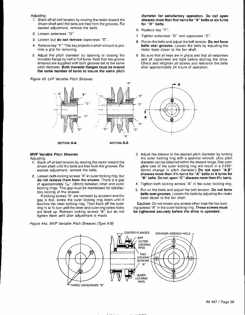
Adjusting:l.-
2.
3.
4.
5.
Slack off all belt tension by moving the motor toward thedriven shaft until the belts are free from the grooves. Foreasiest adjustment, remove the belts,
6Loosen setscrews “D”.
7.Loosen but do not remove capscrews “E”.
8Remove key “F”. This key projects a small amount to pro-vide a grip for removing.
Adjust the pitch diameter by opening or closinq the 9.movable flange by half or full turns. Note that two-groovesheaves are supplied with both grooves set at the samepitch diameter, Both movable flanges must be movedthe same number of turns to insure the same pitch
Figure 43. LVP Variable Pitch Sheaves“N’
diameter for satisfactory operation. Do not opensheaves more than five turns for “A’ belts or six turnsfor “B” belts.
Replace key “F”.
Tighten setscrews “D” and capscrews “E”.
Put on the belts and adjust the belt tension. Do not forcebelts over grooves. Loosen the belts by adjusting themotor base closer to the fan shaft.
Be sure that all kevs are in place and that all setscrews
I
-.~,,! --,
,,,;E “E”
. .
“c”: L. “c”
and all capscrews are tight before starting the drive,Check and retighten all screws and retension the beltsafter approximately 24 hours of operation,
,.. . .F“
.1
..’
SECTION ~-~
MVP Variable Pitch SheavesAdiustina:
L-.
,;
‘F”..’
“B”
SECTION A-A
1.’ Sla~k off all belt tension by moving the motor toward thedriven shaft until the belts are free from the grooves. Foreasiest adjustment, remove the belts.
2. Loosen both locking screws “A” in outer locking ring, butdo not remove them from the sheave. There is a gapof approximately 1/32” (.8mm) between inner and outerlocking rings. This gap must be maintained for satisfac-tory locking of the sheave.
If locking screws “A” are removed by accident and thegap is lost, screw the outer locking ring down until ittouches the inner locking ring. Then back off the outerring 1/2to3/4 turn until the inner and outer ring screw holesare lined up. Reinsert locking screws “A”, but do nottighten them until after adjustment is made.
Figure 44a. MVP Variable Pitch Sheaves (TYpe A-B)
0“ u\
3. Adjust the sheave to the desired pitch diameter by turningthe outer locking ring with a spanner wrench. (Any pitchdiameter can be obtained within the sheave range. One com-plete turn of the outer locking ring will result in a 0.233”(6mm) change in pitch diameter.) Do not open “A-B”sheaves more than 43/4turns for “A’ belts or 6 turns for“B” belts. Do not open “C” sheaves more than 91/2turns.
4. Tighten both locking screws “A” in the outer locking ring.
5. Put on the belts and adjust the belt tension. Do not forcebelts over grooves. Loosen the belts by adjusting the motorbase closer to the fan shaft.
Caution: Do not loosen any screws other than the two lock-ing screws “A” in the outer locking ring. These screws mustbe tightened securely before the drive is operated.
_ CENTER FLANGES SPANNER WRENCH HOLE 7
IM 487 I Page 59

Figure 44b. MVP Variable Pitch Sheaves (Vpe C)
& BARREL FLANGE E
Gs
Final Control
When all start-up procedures have been completed, set thecontrols and program the MicroTech controller for normaloperation. Use the following list as a guide; some items maynot apply to your unit.
1.
2.
3.
4.
5.
6.
7.
8.
9.
10,
Turn system switch S1 to “On.”
Turn gas furnace switch S3 to “Auto,” or turn electric heatswitch HS1 to “On. ”
Set the electromechanical (Honeywell H205) enthalpycontrol (OAE) as required (A, B, C, or D). Set the solid-state (Honeywell H705/C7400) enthalpy control (OAE/RAE) past “D”.
Set the heating and cooling control parameters as re-quired (keypad menus 12 through 14).
Set the high ambient heating lockout setpoint, “MaxOAT=” (keypad menu 14), as required.
Set the alarm limits as required (keypad menu 15).
Set the unoccupied heating and cooling setpoints as re-quired (keypad menu 17).
Set the duct static pressure control parameters as re-quired (keypad menu 18).
Set the fan tracking or building static pressure controlparameters as required (keypad menu 19).
Set the economizer control parameters as required(keypad menu 21).
12.
13.
14.
15.
CENTER FLANGEASSEMBLY
Settings
points on dirty filter switches PC5 (filter) and PC6 (op-tional final filter). The maximum recommended settingsare 0.5” W.C. (124 Pa) for throwaway-type filters, 1.0” (249Pa) W.C. for 30% pleat-type filters, and 1.5” W.C. (374 Pa)for cartridge-type filters.
Set the control timers as required (keypad menu 23).
Set the date and time (keypad menu 24).
Set the operating schedule as required (keypad menus25 and 26).
Place the unit into the Calibrate mode by selecting it fromkeypad menu 11, “Control Mode.” Calibrate will automati-cally zero all pressure sensors and calibrate any actuatorfeedback pots connected to the MicroTech controller.When Calibrate is finished, set the control mode asrequired.
Maintaining Control Parameter RecordsIt is recommended that the MicroTech controller’s setpointsand parameters be recorded and saved for future reference.If the Microprocessor Control Board ever requires replace-ment, this record will facilitate entering the unit’s proper data.Using the following table, record the data directly on the pages(with a pencil) or on photocopies of the pages. Keep thisrecord in a safe place and remember to update it wheneverfurther changes are made.
Page 60 / IM 487

Control Parameter Record
MenuNo.
11
12
12
13
13
Menu Name
Control Mode
Ht/Cl Chgovr (VAV & CAV-DTC)
Heat/Cool (CAV-ZTC)
Clg Control (VAV & CAV-DTC)L
Menu item . FinalSetting
Off-ManualAutoOccupiedOcc-Cool OnlyOcc-Heat OnlvOcc-Fan Only’
Cntl Temp = ReturnSpaceOAT INetwork
Cooling Spt = _ Deg. F. (“C)
Heating Spt = _ Deg. F. (“C)
Clg Diff = _ Deg. F. (“C)
Keypad
Cooling Spt = _Deg. F(” C)
Heating Spt = _Deg. F(” C)
Clg Deadband = _ Deg. F (oC)I
Htg Deadband = _ Deg. F (“C)/
Max Step = _ 0/0
Setpoint = _ Deg. F. (“C)
Min OAT. _ Deg. F (“C)
Min Spt = _Deg. F(° C)
Reset = No ResetSpaceReturnOATNetworkExternalAirflow
Min Spt @ = _Deg, F(o C)
Max Spt @. _ Deg. F(” C)
Stg Timer= _ Min.
Deadband = _ Deg. F(o C)
Mod Limit = _ Min
Wait Time = — Sec.Max Time = — Sec.
Clg Control (CAV-ZTC) Setpoint = _ Deg. F(o C) (Status Only)
Mod Limit = _Deg. F(° C)
Wait Time = _Deg. F(” C)I
Max Step = _ Deg. F (“C)
Continued
IM 487 I Page 61
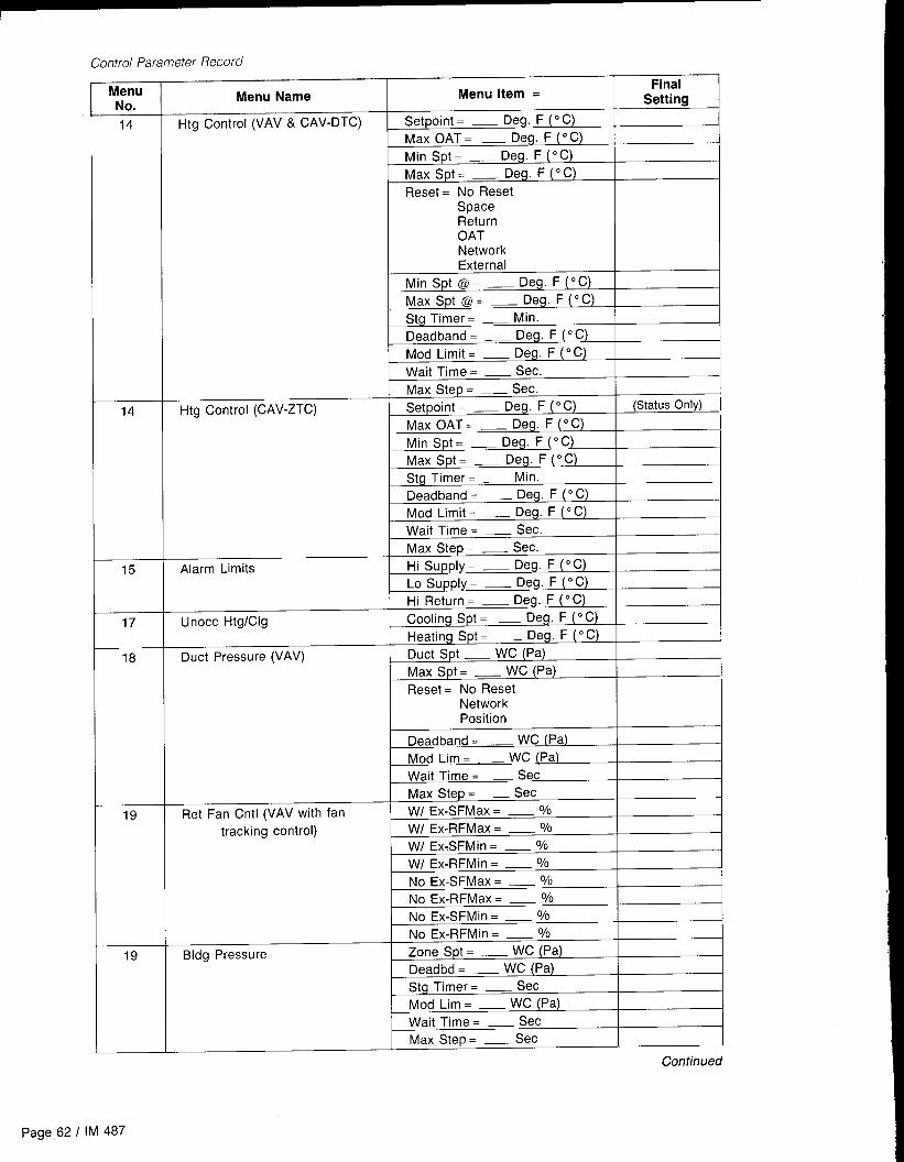
I Control Parameter Record
MenuNo.
14
14
15
17
18
19
19
Menu Name Menu Item =Final
Settirm 1
Htg Control (VAV & CAV-DTC) Setpoint = _ Deg. F (“C)
Max OAT = _Deg. F(° C)
Min Spt = _ Deg. F(o C)
Max Spt = — Deg. F (“C)
Reset = No ResetSpaceReturnOATNetworkExternal
Min Spt @ = _Deg, F(o C)
Max Spt @ = _ Deg. F (“C)
Stg Timer= _ Min.
Deadband = _Deg. F(o C)
Mod Limit = _ Deg. F(” C)
Wait Time = — Sec.
Max Step = — Sec.
Htg Control (CAV-ZTC) Setpoint = _ Deg. F(o C) (Status Only)
Max OAT= — Deg. F (“C)
Min Spt= _Deg. F(° C)
Max Spt = _ Deg. F(o C)
Stg Timer= _ Min.
Deadband = _Deg. F(o C)
Mod Limit = _ Deg. F (“C)
Wait Time = — Sec.
Max Step = — Sec.
Alarm Limits Hi Supply= _ Deg. F(o C)
Lo SUpply = _Deg. F (“C)
Hi Return= _ Deg. F(o C)
Unocc Htg/Clg Cooling Spt = _Deg, F(o C)
Heating Spt = _Deg. F (“C)
Duct Pressure (VAV) Duct Spt — WC (Pa)
Max Spt = _ WC (Pa)
Ffeset = No Reset
NetworkPosition
Deadband = _ WC (Pa)
Mod Lim = _ WC (Pa)
Wait Time = — Sec
Max Step = — Sec
Ret Fan Cntl (VAV with fan W/ Ex-SFMax = _ 0/0
tracking control) W/ Ex-RFMax = — %
W/ Ex-SFMin = _ 0/0
W/ Ex-RFMin = _ 0/0
No Ex-SFMax = _ 0/0
No Ex-RFMax = _ 0/0
No Ex-SFMin = _ 0/0
No Ex-RFMin = _ 0/0
Bldg Pressure Zone Spt = _ WC (Pa)
Deadbd = _ WC (Pa)
Stg Timer= — Sec
Mod Lim = _ WC (Pa)
Wait Time = — Sec
Max Step = — Sec
Continued
page 62 / IM 487

Control Parameter Record (cent ‘d)
MenuNo. Menu Name Menu item = Final
Setting21 Outdr Damper (VAV) Min Airflow. _ 0/0
Auto Adjust = NoneAuto
Enthalpy = Yes
21
NoChangeover. _ Deg. F (“C)Max Purge = _ MinDeadband. _ Deg. F (“C)Mod Limit. _ Deg. F (“C)Wait Time = — SecMax Step. _ Sec
Outdr Damper (CAV) Min Airflow. _ 0/0
Enthalpy = YesNo
Changeover. _ Deg. F (“C)Max Purge = _ MinDeadband. _ Deg. F (“C)Mod Limit. _ Deg. F (“C)Wait Time = — SecMax Step = — Sec
22 Dirty Filter Ist Fltr. _ WC (Pa)Fnl Fltr = _ WC (Pa)
23 Timers Recirc = _ MinOvrde Inc = _ Hr
Max MWUP.25
_ MinSchedule override = _ Hr
NMP Sched No. = _
Sun hr:mn-hr.mn
Mon hr:mn-hr. mn
Tue hr:mn-hr. mn
Wed hr:mn-hr.mn
Thu hr:mn-hr.mn
Fri hr:mn-hr.mn
Sat hr:mn-hr,mn
Hol hr:mn-hr.mn
Continued
IM 487 I Page 63

28
Control Parameter Record (cent’d)Final
Menu Menu Name Menu Item =No.
Setting
26 Holiday Date#l Date= MON DY
#1 Dur= —Day(s)#2 Date= MON DY
#2 Dur = — Day(s)
#3 Date= MON Dy
#3 Dur= — Day(s)#4 Date= MON DY
#4 Dur= —Day(s)#5 Date= MON Dy
#5 Dur= — Day(s)
#6 Date= MON DY
#6 Dur= — Day(s)
#7 Date. MON DY
#7 Dur= — Day(s)
#8 Date= MON DY
#8 Dur= — Day(s)
#9 Date= MON DY
#9 Dur= —Day(s)
#10 Date = MON DY
#lo Dur= — Day(s)
#11 Date = MON DY
#11 Dur= — Day(s)
#12 Date = MON D’f
#12 Dur= — Day(s)#13 Date = MON DY
#13 Dur= — Day(s)
#14 Date = MON DY
#14 Dur= —Day(s)
ServiceMode = Normal Normal
Shutdown
Timers = Normal Normal
Fast
space Sensor = YesNo
IDENT =
page 64 I IM 487

Maintenance
I Installation and maintenance are to be performed only by qualified personnel who are experienced with this typeof equipment and familiar with local codes and regulations. I
Moving machinery and electrical power hazards. May causesevere personal injury or death.
Disconnect and lock off power before servicing equipment.
PreventivePreventive maintenance is the best way to avoid unnecessaryexpense and inconvenience, Have this system inspected atregular intervals by a qualified service technician. The re-quired frequency of inspections depends upon the total oper-ating time and the indoor and outdoor environmental condi-tions, Routine maintenance should cover the following items:
1.
2.
3.
4.
5.
Tighten all belts, wire connections, and setscrews.
Clean the evaporator and condenser coils mechanicallyor with cold water, if necessary. Usually any fouling is onlymatted on the entering air face of the coil and can beremoved by brushing.
Lubricate the motor and fan shaft bearings (see below).
Align or replace the belts as needed.
Clean or replace the filters as needed.
Sharp edges are inherent to sheet metal parts, screws, clips,and similar items. May cause personal injury.
Exercise caution when servicing equipment.
Maintenance6.
7.
8,
9.
10.
11.
12.
13.
14.
Check for blockage of the condensate drain. Clean thecondensate pan as needed.
Check the power and control voltages,
Check the running amperage of all motors.
Check all operating temperatures and pressures,
Check and adjust all temperature and pressure controlsas needed.
Check and adjust all damper linkages as needed.
Check the operation of all safety controls.
Examine the gas furnace (see Bulletin No, IM 484),
Lubricate the door latch mechanisms,
Unit StorageIf air handling units are to be stored for any period of time, is important to keep the fan bearings lubricated. If the fanit is important to periodically rotate the fan wheel. The fan wheel is not periodically rotated, grease will settle in the lowerwheel needs to be rotated to prevent any deflection in the fan part of the bearing. This can lead to oxidation on the uppershaft which could cause unbalanced fan operation. Also it portion of the bearing surface which can cause bearing failure,
Gas FurnaceFor information on maintenance of the gas furnace, refer to Bulletin No. IM 484,
Bearing Lubrication
Bearing overheating potential. Can cause damage to the equipment.
Do not overlubricate bearings.
Use only a high grade mineral grease with a 200F (93” C) safe operating temperature, Refer to Table 13 for specific recommendedlubricants.
Motor Bearings 2. Insert a grease fitting into the upper hole and add a small
Supply and Return Fansamount of clean grease with a low pressure gun.
Supply and return fan motors should have grease added after 3. Run the motor for five minutes before replacing the plugs.every 2,000 hours of operation. Use one of the greases shownin Table 13 on page 66. Using the following procedure, relubri-
Note: Specific greasing instructions may be found on a tag
I cate the bearings while the motor is warm, but not running.attached to the motor. If special lubrication instructions areon the motor, they will supersede all other instructions,
1. Remove and clean upper and lower grease plugs.
IM 487 I Page 65

Table 13. Recommended Greases
Manufacturer Product Name Temperature Range 0F (“C)
Texaco Lubricants Co. Premium RB -30to 300 (-34to 149”C)
Keystone Ind. Lubricants B4EP-2 -40 to 200 (-40 to 93”C)
Mobile Oil Corporation Mobilth AW 2 -40 to 325 (-40 to 163”C)
Chevron U.S.A. Inc. SRI-2 -20 to 325 (-29 to 163° C)
Exxon Company, U.S.A. Ronex MP -40 to 300 (-29 to 149”C)
Shell Oil Company Alvania No. 2 -20t0240( -29to116°C)
Fan Shaft Bearings tions, relubricate more frequently. Use one of the greasesshown in Table 13.
Fan shaft bearings should be relubricated periodically. While the bearings is at normal operating temperature,
Relubricate according to the schedule shown in Table 14. rotate the fan by hand and add only enough grease to purge
If the bearings are exposed to wet conditions, wide the seals. The seals will bleed slightly when this has occur-
temperature variations, or other severe atmospheric condi- red. Do not overlubricate.
Table 14. Recommended Fan Shaft Bearing Relubrication Interval
Operating Bearing Ambient Temperature
Duty TO 1300F (54” C) TO 150” F (66° C) Over 1500 F (66 “C)
Continuous 6 months 4 months 2 months
12 hours per day 12 months 12 months 6 months
SetscrewsSetscrews lock bearings, sheaves, locking collars, and fanwheels to their shafts. It is very important that all setscrewsbe checked periodically to assure that they have not loosen-ed. If this is not done, severe equipment damage could occur.
Using Table 15, check the tightness of all setscrews witha torque wrench. Note that if the return fan bearing setscrewsmust be retightened, a special procedure is required to equallyload both bearings (see below).
Table 15. Setscrew Minimum Torque Specification
Setscrew Diameter (In.) Minimum Torque (Ft.-Lb.)
114 5.5 (.76 kg-m)
5/16 10.5 (1.45 kg-m)
318 19.0 (2.63 kg-m)
7116 29.0 (4.00 kg-m)
112 42.0 (5.81 kg-m)
518 92.0 (12.72 kg-m)
Return Fan Bearing SetscrewsBecause the return fan is mounted on a vertical shaft, the fol-lowing procedure must be used to retighten any return fanbearing setscrews that have loosened. This procedure will as-sure that both bearings are equally loaded. If one bearing iscarrying the entire weight of the fan, it could fail prematurely.
1.
2.
Loosen the fan belts.
Support the weight of the fan and fan shaft with timbersor some other suitable means (see Figure 45).
Important: In order to maintain proper drive alignmentand fan-to-funnel clearance, the fan and shaft must notdrop at all when the setscrews are loosened in Step 4below.
Figure 45.
I
FAN UPPER SHAFTWHEEL COLLAR
FAN SHAFTSUPPORT
AFT
3.
4.
5.
6.
Verify that the upper shaft collar is securely fastened tothe shaft. Check the setscrew torque.
Loosen the upper and lower bearing setscrews and thelower shaft collar setscrews. The entire weight of the fanand shaft is now supported by the fan shaft support.
Retighten all bearing and shaft collar setscrews to the tor-que specification given in Table 15 above.
Remove the fan shaft support and retension the belts.
Airfoil Supply Fan Wheel-to-Funnel Alignment
If the unit is equipped with an airfoil supply fan, the fan wheel- along the shaft as necessary to obtain the correct dimen-to-funnel alignment must be as shown in Figures 46 and 47 sion “A”..- .-.and Tables-16 and 17 to obtain proper air delivery andoperating clearance. If necessary, adjustments are made as
3. Retighten the setscrews to the torque specification given
follows.in Table 15. Tighten the setscrews over the keyways first;tighten those at 90° to the keyway last.
1. Verify that the fan shaft has not moved in its bearings.. .
4. Verify that the radial clearance around the fan is uniform.2. Loosen the fan hub setscrews and move the wheel(s) Radial clearance can be adjusted by slightly Ioosening
the funnel hold]down fasteners, shifting the funnel as re-
Page 66 I IM 487quired, and retightening the fasteners.
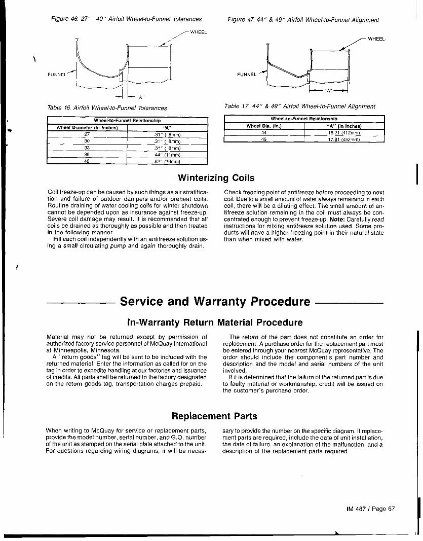
\
Figure 46, 27”-40” Airfoil Wheel-to-funnel Tolerances
/-WHEEL
/
FUNNEL<
--/ +A
Table 16, Airfoil Wheel-to-Funnel Tolerances
Wheel-to-Funnel Relationship
Wheel Diameter (in Inches) A,, ,>
27 .31” ( 8mm)
30 .31” ( 8mm)
33 .31” ( 8mm)
36 .44” (Ilmm)
40 .62” (18mm)
Figure 4T 44” & 49” Airfoil Wheel-to-Funnel Alignment
_ WHEEL.
!-- ‘w’ --+
Table 17.44” & 49” Airfoil Wheel-to-Funnel Alignment
Wheel-to-Funnel Relationship
Wheel Dia. (In.) “A” (In Inches)
44 16.21 (412mm)
I 49 I 17.81 (452mm) I
Winterizing Coils
Coil freeze-up can be caused by such things as air stratifica- Check freezing point of antifreeze before proceeding to nexttion and failure of outdoor dampers and/or preheat coils. coil. Due to a small amount of water always remaining in eachRoutine draining of water cooling coils for winter shutdown coil, there will be a diluting effect. The small amount of an-cannot be depended upon as insurance against freeze-up. tifreeze solution remaining in the coil must always be con-Severe coil damage may result. It is recommended that all centrated enough to prevent freeze-up. Note: Carefully readcoils be drained as thoroughly as possible and then treated instructions for mixing antifreeze solution used, Some pro-in the following manner. ducts will have a higher freezing point in their natural state
Fill each coil independently with an antifreeze solution us- than when mixed with water.ing a small circulating pump and again thoroughly drain.
Service and Warranty Procedure
Material may not be returned except by permission ofauthorized factory service personnel of McQuay Internationalat Minneapolis, Minnesota.
A “return goods” tag will be sent to be included with thereturned material, Enter the information as called for on thetag in order to expedite handling at our factories and issuanceof credits. All parts shall be returned to the factory designatedon the return goods tag, transportation charges prepaid.
The return of the part does not constitute an order forreplacement. A purchase order for the replacement part mustbe entered through your nearest McQuay representative. Theorder should include the component’s part number anddescription and the model and serial numbers of the unitinvolved,
If it is determined that the failure of the returned part is dueto faulty material or workmanship, credit will be issued onthe customer’s purchase order.
\
IM 487 / Page 67
L
In-Warranty Return Material Procedure
Replacement Parts
When writing to McQuay for service or replacement parts, sary to provide the number on the specific diagram. If replace-provide the model number, serial number, and G.0, number ment parts are required, include the date of unit installation,of the unit as stamped on the serial plate attached to the unit. the date of failure, an explanation of the malfunction, and aFor questions regarding wiring diagrams, it will be neces- description of the replacement parts required,
Product WarrantyMcQuay International, hereinafter referred to as the “Com-pany,” warrants that it will provide, at the Company’s option,either free replacement parts or free repair of component partsin the event any product manufactured by the Company andused in the United States proves defective in material orworkmanship within twelve (12) months from initial start-upor eighteen (18) months from the date shipped by the Com-pany, whichever comes first. For an additional consideration,the Company warrants that for nine (9) years following theinitial warranty period it will provide free replacement of theheat exchanger in gas-fired or oil-fired furnaces which pro-ves defective in material and workmanship. (Extended war-ranties for heat exchangers are not applicable unlessseparately purchased.)
To obtain assistance under the parts warranty or extendedheat exchanger warranty, simply contact the selling agency.To obtain information or to gain factory help, contact McQuayInternational, Warranty Claims Department, PO. Box 1551,Minneapolis, MN 55440; telephone (612) 553-5330.
This warranty constitutes the buyer’s sole remedy. It isgiven in lieu of all other warranties. There is no impliedwarranty of merchantability or fitness for a particular pur-pose. In no event and under no circumstances shall theCompany be liable for incidental or consequentialdamages, whether the theory be breach of this or any
other warranty, negligence or strict tort.This parts warranty and the optional extended warranties
extend only to the original user. Of course, abuse, misuse, /or alteration of the product in any manner voids the Com-pany’s warranty obligation. Neither the parts nor extendedwarranty obligates the Company to pay any labor or servicecosts for removing or replacing parts, or any shipping charges.Refrigerants, fluids, oils, and expendable items such as filtersare not covered by this warranty.
The extended warranties apply only to integral componentsof the heat exchanger, not to refrigerant controls, electricalcontrols, or mechanical controls, or to failures caused byfailure of those controls.
Attached to this warranty is a requirement for equipmentcontaining furnaces to report start-up information. Theregistration form accompanying the product must be com-pleted and returned to the Company within ten (10) days oforiginal equipment start-up. If that is not done, the date of ship-ment shall be presumed to be the date of start-up, and thewarranty shall expire twelve (12) months from that date.
No person (including any agent, salesman, dealer ordistributor) has authority to extend the Company’s obligationbeyond the terms of this express warranty, or to state that theperformance of the product is other than that published bythe Company,
MeQuaY”13600 Industrial Park Boulevard, P.O. Box 1551, Minneapolis, MN 55440 USA (612) 553-5330 October 1996
@Printedcm recycled papercontaining at least 10%post-consurner recycled material