Embed Size (px)
Citation preview

Robot Module System� P Series Module Main Unit� R Series Module Main Unit� EXEA Controller
User’s Manual 2
= Programming and Operation of EXEA Controller =
1 Installation and Maintenanceof EXEA Controller
1. Introduction 2. Safety Precautions 3. System Configuration 4. Glossary 5. Reference Number • Specifications 6. Unpacking and Installation 7. Wiring 8. Startup 9. Initial Setting 10. Trial Running 11. Protection and Safety 12. Maintenance • Checking 13. Alarms 14. TroubleshootingAppendix
2 Programming and Operationof EXEA Controller
15. Programming 16. Description of Function 17. Operation of Robot Module 18. Remote Control Operation
3 Installation and Maintenanceof Module Main Unit
19. Reference Number • Specifications 20. Unpacking 21. Installation 22. Maintenance • Checking
Document Number: K20079-01
EC-T
M–E099XE0K2–023

Limited Warranty
NSK Ltd. warrants its products to be free from defects in material and/or workmanship which NSKLtd. is notified of in writing within, which comes first, one (1) year of shipment or 2400 totaloperation hours. NSK Ltd., at its option, and with transportation charges prepaid by the claimant,will repair or replace any product which has been proved to the satisfaction of NSK Ltd. to have adefect in material and/or workmanship.
This warranty is the sole and exclusive remedy available, and under no circumstances shall NSKLtd. be liable for any consequential damages, loss of profits and/or personal injury as a result ofclaim arising under this limited warranty. NSK Ltd. makes no other warranty express or implied,and disclaims any warranties for fitness for a particular purpose or merchantability.
Copyright 2000 by NSK Ltd., Tokyo, Japan
All rights reserved.
No part of this publication may be reproduced in anyform or by any means without permission in writing fromNSK Ltd.
NSK Ltd. reserves the right to make changes to anyproducts herein to improve reliability, function or designwithout prior notice and without any obligation.
NSK Ltd. does not assume any liability arising out of theapplication or use of any product described herein;neither does it convey any licence under its present patentnor the rights of others.
Patents issued and patents pending.

— i —
Robot Module SystemEC Directives Conformity
NSK Ltd. declares that "Robot Module System" conforms to EC Directive (CE Marking).
However, please note that the following conditions are added for conformity to the EC directive.
���� EC Declaration of Incorporation
� NSK Ltd. declares that the Robot Module System is a machine component which is to beincorporated into the machine. ( EC Declaration of Incorporation )
� The Robot Module System must not be operated until it is incorporated to the machine.
� The Robot Module System, as the machine component, conforms with following EC Directives.
� EC Machinery Directive 89/392 as amended 94/368 and 93/44.� EC Low Voltage Directive 73/23 as amended 93/68.
� The customer has to take appropriate measures to its machine to conform to ElectromagneticCompatibility Directive. The Robot Module must not put into service until the machinery intowhich it to be incorporated has been declared in conformity with the provisions of ECDirectives.
� Our declaration becomes invalid if technical or operational modifications are introduced withoutthe consent of Mechatronics Technology Department of NSK Ltd.
���� Remaining Hazards(Following notes should be observed for your safety.)
� EXEA controller shall be put into the enclosure conforming to relevant European standard interms of fire protection and electrical shock protection. The protection grade of the enclosuremust be IP 54 or better. EXEA controller shall not be exposed to water or oil.
� Just after the power is turned on and off, there will be the hazardous voltage on the parts ofEXEA controller, such as the power input terminal, motor connector and connector for anexternal regenerative dump resistor. Put covers on those parts to protect from touching whenoperating the machine or doing maintenance work.Furthermore, provide appropriate protection from disconnecting the motor connector accidentally.
� An isolation transformer must be used to prevent electrical shock. The isolation transformermust have enough capacity for the Robot Module System power consumption.
� Install noise filter in the primary AC power line as a measure for Electromagnetic CompatibilityDirective.
� A circuit breaker must be installed to the primary AC power line of Robot Module System.
� Ground earthing must be provided to EXEA controller.
� Wiring inside of EXEA controller is simply internal wirings and the grounding wire is notdistinguished by color as the protective grounding conductive.
� Secure the controller cables and motor cables firmly so that those cables do not break or haveloose contact.
� Surround the machine, to which the Robot Module System is incorporated, with safety fence toprevent any personnel from entering its moving range.

— ii —
���� Unit Limitation
� Units of Robot Module System which conform to EC Directives are limited to the followingreference number only.
1. EXEA controllerReference No. : M-EXEA � – � � � � T � �
�
T : Indicates conformity with the Directive
2. Teaching BoxReference No. : M-EXTB 04
� However, all robot module main units are compatible with the EC Directives. If you require tobuild the Robot Module System that complies to the EC Directives, the EXEA controller andthe Teaching Box must be compatible with the EC Directives.

- iii -
Contents15. Programming-------------------------------15-1
15.1. Teaching -------------------------------------------------15-115.1.1. List of Teaching Function --------------------15-315.1.2. Teaching by Jog Operation ------------------15-4
15.1.2.1. Teaching Procedure byJog Operation ----------------------------15-4
15.1.2.2. Automatic Positioning toEditing Point ------------------------------15-6
15.1.3. Teaching by Manual Data Input ------------15-815.1.4. Saving Point Data ------------------------------15-915.1.5. Readout of Point Data ---------------------- 15-1015.1.6. Deleting point Data -------------------------- 15-1115.1.7. Copying Point Data -------------------------- 15-12
15.2. Programming ----------------------------------------- 15-1315.2.1. Programming Area--------------------------- 15-1315.2.2. List of Programming Mode----------------- 15-1615.2.3. Programming Procedure ------------------- 15-19
15.2.3.1. Programming Screen ---------------- 15-2115.2.3.2. Setting Procedure for
Program Number ---------------------- 15-2115.2.3.3. Procedure for Deleting Program -- 15-2215.2.3.4. Procedure for Copying Program -- 15-2315.2.3.5. Procedure for Saving Program ---- 15-2415.2.3.6. Procedure for Reading out
Program---------------------------------- 15-2515.2.4. Program Editing Screen -------------------- 15-26
15.2.4.1. Procedure for Entering Name ofProgram---------------------------------- 15-26
15.2.4.2. Inputting Memo to Program -------- 15-2715.2.4.3. Procedure for Changing Program
Number ---------------------------------- 15-2815.2.4.4. Procedure for Changing
Step Number --------------------------- 15-2915.2.4.5. Procedure for Copying
Program Command------------------- 15-3015.2.4.6. Procedure for Inserting Program
Command ------------------------------- 15-3115.2.4.7. Procedure for Deleting Program
Command ------------------------------- 15-3215.2.5. Editing Program Command---------------- 15-33
15.2.5.1. Editing / Setting of ProgramCommand ------------------------------- 15-33
15.2.5.2. List of Program Command---------- 15-3515.2.5.3. Editing Motion Command ----------- 15-3615.2.5.4. Editing Sequence Control
Command ------------------------------- 15-3815.2.5.5. Editing Data Control Command --- 15-4015.2.5.6. Editing Palletizing Motion Command
(Multi-axis Combination only.)------ 15-4215.2.5.7. Editing Subroutine Execution
Command ------------------------------- 15-4315.2.5.8. Command for Operating Condition
Control ----------------------------------- 15-4515.2.5.9. Sub-menu ------------------------------- 15-47
15.2.6. Procedure for Editing ProgramCommand---------------------------------------15-54
15.2.6.1. Editing Program Command: MOV 15-5515.2.6.2. Editing Program Command: ARC
(for multi-axis combination only.) --15-5815.2.6.3. Editing Program Command: TIM--15-5915.2.6.4. Editing Program Command: OUT-15-6015.2.6.5. Editing Program Command: PALI
(for multi-axis combination only.) --15-6115.2.6.6. Editing Program Command
: CALL ------------------------------------15-6315.2.6.7. Editing Program Command: UNT
(for multi-axis combination only.) --15-6415.2.6.8. Editing Program Command: END-15-6515.2.6.9. Editing Program Command
: Recovery from Syntax Error-------15-6615.2.7. Description of Program Command-------15-67
15.2.7.1. Usable Data for Program------------15-6715.2.7.2. Symbol List to Describe Syntax of
Program Command -------------------15-7315.2.7.3. Program Command-------------------15-74
15.3. Examples of Program----------------------------- 15-11415.3.1. MOV Command : Single Axis System- 15-11415.3.2. MOV Command in Two Axes Motion-- 15-11615.3.3. ARC Command in Two Axes Motion -- 15-12015.3.4. CIR Command in Two Axes Motion --- 15-12315.3.5. Continue Path in Two Axes motion ---- 15-12615.3.6. Arch Motion in Two Axes Motion ------- 15-12815.3.7. Palletizing in Two Axes Motion---------- 15-13015.3.8. Multitask -------------------------------------- 15-132
15.3.8.1. Example of Program 1 ------------- 15-13215.3.8.2. Example of Program 2
(2 axes motion)----------------------- 15-135

- iv -
16. Description of Function------------------16-116.1. Palletizing (Multi-axis combination only)---------16-1
16.1.1. Outline of Palletizing Operation-------------16-116.1.1.1. Description of Terms -------------------16-216.1.1.2. Programming Procedure
for Palletizing -----------------------------16-416.1.1.2. Programming Procedure
for Palletizing -----------------------------16-416.1.2. Outline of Palletizing Program Mode------16-5
16.1.2.1. Screen of PalletizingProgram Mode ---------------------------16-6
16.1.3. Setting Palletizing Pattern Data ------------16-716.1.4. Editing Palletizing Pattern Data-------------16-8
16.1.4.1. Naming Palletizing Pattern -----------16-916.1.4.2. Writing Memo ----------------------------16-916.1.4.3. Format of Palletizing
Position Setting ------------------------ 16-1016.1.4.4. Setting Operating Unit --------------- 16-1116.1.4.5. Setting Start Position----------------- 16-1216.1.4.6. Setting Position Interval ------------- 16-1316.1.4.7. Setting Position of
Corner Point X ------------------------- 16-1416.1.4.8. Setting Position of
Corner Point Y ------------------------- 16-1516.1.4.9. Setting Number of
Position Intervals ---------------------- 16-1616.1.4.10. Setting Moving Order--------------- 16-1716.1.4.11. Selection of Jump Format--------- 16-1816.1.4.12. Format Selection of
Coordinate Data Development--- 16-1916.1.5. Development of Palletizing Data --------- 16-2016.1.6. Clear Palletizing Data ----------------------- 16-2116.1.7. Copy Palletizing Data ----------------------- 16-2216.1.8. Saving Palletizing Data --------------------- 16-23
16.2. Arch Motion (Malti-axis combination only) ---- 16-2416.2.1. Initial Setting----------------------------------- 16-2516.2.2. Programming ---------------------------------- 16-26
16.3. Continuous Path(Malti-axis combination only) --------------------- 16-27
16.3.1. Command for Continuous Path----------- 16-2716.3.2. Restrictions on Program of
Continuous Path ------------------------------ 16-2816.3.2.1. Change Direction of
Linear Motion --------------------------- 16-2816.3.2.2. Number of Steps between
CPS and CPE Commands---------- 16-2916.3.2.3. Others------------------------------------ 16-29
16.4. Multitask ----------------------------------------------- 16-3016.4.1. Multitask Program---------------------------- 16-31
16.4.1.1. Main and Sub Programs ------------ 16-3116.4.1.2. Parallel Processing ------------------- 16-32
16.5. Direct Operation ------------------------------------- 16-33
17. Operation of Robot Module ---------------- 117.1. Power On and Off------------------------------------------117.2. Checking before Start Operation ----------------------317.3. Operation by Teaching Box -----------------------------4
17.3.1. Home Return ----------------------------------------417.3.2. Jog Operation ---------------------------------------5
17.3.2.1. Sequential Timing of Jog Operation----617.3.3. Programmed Operation by Teaching Box----7
17.3.3.1. Sequential Programmed Operation ----717.4. Operation in External Control Mode ------------------9
17.4.1. Operation Procedures in ExternalControl Mode ----------------------------------------9
17.4.2. Servo on -------------------------------------------- 1017.4.3. Home Return -------------------------------------- 1117.4.4. Programmed Operation------------------------- 1317.4.5. Stopping Programmed Operation ------------ 1517.4.6. Operating Teaching Box------------------------ 17
17.4.6.1. Monitor of Operation Status ------------ 1717.4.6.2. I / O Monitor--------------------------------- 1717.4.6.3. Monitor of Software Version and
Alarm History ------------------------------- 2317.5. Operational Function------------------------------------ 25
17.5.1. Home Return -------------------------------------- 2517.5.1.1. Function of Home Return --------------- 2517.5.1.2. Outline of Home Return ----------------- 2517.5.1.3. Signal Timing of Home Return
(Multi-axis combination only) ----------- 2617.5.2. Resume Programmed Operation------------- 27
17.5.2.1. Procedure to Resume ProgrammedOperation in External Control Mode--------------- 2817.5.2.2. Procedure to Resume Programmed
Operation in Teaching BoxControl Mode ------------------------------- 31
17.5.3. Output of In-position ----------------------------- 3217.5.4. Pulse Train Input
(Single axis system only) ----------------------- 3417.5.4.1. Function of Pulse Train Input ---------- 3417.5.4.2. Description of Operation----------------- 3417.5.4.3. Input Timing -------------------------------- 35

- v -
18. Remote Control Operation -------------18-118.1. Interface Specification--------------------------------18-218.2. Outline of Remote Control --------------------------18-2
18.2.1. Outline---------------------------------------------18-218.2.2. Caution for Remote Control -----------------18-5
18.3. Startup of Remote Control --------------------------18-618.3.1. Startup Procedure------------------------------18-6
18.4. Operation Command of Remote Control --------18-718.4.1. Command List-----------------------------------18-718.4.2. Description of Command---------------------18-9
18.4.2.1. First Level Command ------------------18-918.4.2.2. Mode Declaration Command ------ 18-1518.4.2.3. MOT Mode • Second Level
Command ------------------------------- 18-1718.4.2.4. RUN Mode • Second Level
Command ------------------------------- 18-3018.4.2.5. TCH Mode • Second Level
Command ------------------------------- 18-3518.4.2.6. EDT Mode • Second Level
Command ------------------------------- 18-3818.4.2.7. PAL Mode • Second Level
Command ------------------------------- 18-4218.4.2.8. SYS Mode • Second Level
Command ------------------------------- 18-4618.4.2.9. CTR Mode • Second Level
Command ------------------------------- 18-4918.4.2.10. FNC Mode • Second Level
Command ----------------------------- 18-57

- vi -
(Blank Page)

2 Programming and Operation of EXEA Controller “15. Programming”
— 15-1 —
15. Programming� It is necessary to make operation programs prior to move robot module automatically. On
receiving a start command, the robot module executes the operation in accordance with theprogram.
� Programming is referred to as making instructions by converting sequential operations into thecombination of program command (robot language) provided for the EXEA controller.
� The motion commands that execute positioning specify the point register as a destination ofmotion. Setting the coordinates data to a point register is called “Teaching.” The teachingdecides the destinations of positioning operation of the robot module.
[Example] MOV P0000 : Linear motion to point P0000
Motion command (linear) = Move linearly to the point of which coordinate data is writtenon the point register P0000.
Specify a position register P0000 as the destination.
15.1. Teaching
� Teaching is referred to as a procedure to determine a coordinates data of point register (= data ofpoint register) of a destination point of the motion command in the programmed operation.
� The unit of data is millimeter and its resolution is 0.01 mm.[Example] X0200.05 • • • X axis coordinate = 200.05 mm
* “××××.××” denotes that the robot does not move. When the teaching gives “××××.××,”the robot does not move even the motion command is inputted. (Holds currentposition.)
� Number of point register is available in P0000 to P3999, allowing you to make up to 4000points.
Caution : After the teaching, be sure to save the data to the memory. All data will belost if the power is turned off before data is stored. Refer to “15.1.4. SavingPoint Data.”
Figure 15-1: Construction of point register
X: X axis coordinate dataY: Y axis coordinate dataZ: Z axis coordinate dataR: R axis coordinate data
P0000 X ××××.×× Y ××××.×× Z ××××.×× R ××××.××
P0001 X ××××.×× Y ××××.×× Z ××××.×× R ××××.××
•••
•••
P3999 X ××××.×× Y ××××.×× Z ××××.×× R ××××.××
(Note) : There will be no coordinate data for Y, Z and R axes in a single axis system.
2 Programming and Operation of EXEA Controller “15. Programming”
— 15-2 —
� There are three ways to make the coordinate data.
1) Move the slider to the desired position by jog operation, then set the point register.(Actual setting)
2) Input numerical data manually through the teaching box. (Manual data input)
3) Find out the coordinates arithmetically by a program operating command whileprogramming.This is used when changing the coordinate data of positioning point register whileprogramming.
� When it is necessary to change the teaching data, specify the point register number and performteaching again. New data will be overwritten.
� Two data shown below may be set as the additional information of teaching.
1) Unit number (U�) (Only U1 can be set for a single axis system.)
2) Coordinate format: A (Absolute position) or I (Relative position)(Relative position is not applicable when setting the point register by Jog operation.)
These data are used for the direct operation. Refer to “16.2. Direct Operation” for detail.
� Teaching data won’t be stored automatically. They are lost if the power is turned off beforesaving them. For saving data, select [SAV].
� Select [LOD] to read out the stored data.
Data of the point registers are common to all programs. They won’tbe lost after the main power is turned off, if they are saved inadvance.
Figure 15-2: Construction of Memory
Flash memoryRAM
For back-upFor setting / program
LOD
SAV
For simplification in the description hereafter, “point registerdata” will be referred to as “Point data” and “point registernumber” will be referred to as “point number.”

2 Programming and Operation of EXEA Controller “15. Programming”
— 15-3 —
15.1.1. List of Teaching Function
� Selection of F2 TCH in the Teaching menu screen will make you to get into Teaching mode.
� Setting function of teaching mode is like a tree structure as shown in Figure 15-3. Thesefunctions can be set by selecting the function keys on the teaching box.
Figure 15-3: List of teaching mode
A : Absolute coordinatestyp
Type ( _ ) ?Select coordinateformat. I : Relative coordinates
unt Unit ( _ ) ?Set a unit number.
Unit No. 1 only for a single axis systemUnit No.1 ~ 8 for a multi-axis combination
axs Select an axis tobe edited. X, Y, Z, and R axis *3
X Set coordinate data by jog operation. (X axis)Y Set coordinate data by jog operation. (Y axis) *3
Z Set coordinate data by jog operation. (Z axis) *3
R Set coordinate data by jog operation. (R axis) *3
Select point data number to be edited.
Clear point data being indicated.
Clear point data being indicated.
Select point data number.
CLR (0000>0000)?Specify the beginning and ending pointdata numbers and delete the databetween them.
CLR (ALL )? Delete all point data.
CPY (0000>0000/0000)?Specify the beginning and ending pointdata numbers and copy data betweenthem.
Store all point data.
Read out all stored point data.
Inputpint data
F4
etc
F1 EDT
F1 CLR
F2 CPY
F2 JOG
*1
*2
*1. Indication in case of multi-axis combination.*2. Indication in case of single axis system.*3. Only X axis in case of single axis combination.
F3 numF1 EDT
F4 CLR
F2 num
[TCH]F1 CLR
F1 SAV
F2 LOD
Teaching screen Editing screen
F4
etc
Edit Jog
Select pointdata number
Edit pointdata
Deletepoint data
Select pointdata number
Deletepoint data
Copypoint data
Storepoint data
Read outpoint data
Deletepoint data
Teachingmode
[TCH] 0000 A U1
X ××××.×× Y ××××.××
Z ××××.×× R ××××.××
1SAV 2LOD 4etc
: Teaching screen 3
Indicates a point number: Set it using and keys.
Indicates coordinate format.: Set in the numerical data input
Indicates the unit number. : Set in the numerical datainput editing screen.
* Part in the dotted lines won’t be indicatedfor a single axis system.
*

2 Programming and Operation of EXEA Controller “15. Programming”
— 15-4 —
15.1.2. Teaching by Jog Operation
� Move the slider actually with jog keys ( +X , -X , +Y , -Y , +Z , -Z , +R and -R ) of theteaching box to specify the point data to be used for positioning.
* Use +X and -X only for a single axis system.
� Moving speed and acceleration shall be set by “Jog speed (L)” and “Jog accel” which aredescribed in “9.3.3. Parameters for Jog Operation.”
Danger : Do not enter working area of the robot. Such hazards exist that the robotwould hit, nip or catch a person within its working area when the modulemain unit or EXEA controller malfunctions.
� If you conduct the teaching beyond the guard fence, be careful not to get in theworking area of the robot. Stay in the area from where you can clearly see its motion.Be sure to set to safety speed. (250 mm/Sec or lower)
* Shipping set of the jog and teaching speed is 50 mm/Sec.
� Conduct the jog operation before teaching to confirm that it is set to the safety speed orlower.
� It requires completion of the home return before the teaching by jog operation.
15.1.2.1. Teaching Procedure by Jog Operation
1) Select the editing screen in the teaching screen 1 by pressing F1 key (EDT).
2) Specify a point number using and keys.
3) Then, press F2 key (JOG) to make it possible to perform the jog operation for teaching. Analarm arises if the home return is not completed at this moment.
4) Specify a unit number using and keys. (for multi-axis combination only)
5) Use F1 , F2 , F3 and F4 keys to select or default an axis.
* If an axis is selected, the screen indicated current position while “××××.××” is indicated fora defaulted axis.
* Use F1 key only for a single axis system.
6) Turn the servo on by ON key and move the robot by the jog keys ( +X and -X etc.).
* Use +X and -X keys only for a single axis system.
7) The coordinate format of position data is absolute coordinates.
* Refer to Figure 15-4: Teaching procedure by jog operation.

2 Programming and Operation of EXEA Controller “15. Programming”
— 15-5 —
Figure 15-4: Teaching procedure by jog operation
Press F2 key. (The screen changes to Teaching / Jog editing screen and current position is displayed.)
Press ON key.
: Teaching screen 1
Press F4 key.
: External control mode screen 1
: External control mode screen 2
Press F1 key.: Menu selection screen 1
Press F4 key.: Menu selection screen 2
Press F2 key.
: Teaching screen 1
Press F1 key.
* There will be no indication of the part indicatedby dotted lines for a single axis system.
Set to “Teaching mode” referring to“8.2. Selection of Control Mode.”
: Specify point number.
� Use the jog keys ( +X and -X keys, etc.) to move theslider to desired position, then press SET key toregister the position as a point data. (Use only +X and-X keys for a single axis system.)
� Press ON key to turn the servo on when it is off.� “*” (asterisk) appears on upper right corner of the
screen when the servo is turned on.
: Teaching / Jog editingscreen
: Teaching / Jog editingscreen
[TCH]EJ 0000 A U1 *X0000.00 Y0000.00Z ××××.×× R ××××.××1X 2Y 3Z 4R
[TCH]EJ 0000 A U1X0000.00 Y0000.00Z ××××.×× R ××××.××1X 2Y 3Z 4R
[TCH]E 0000X ××××.×× Y ××××.××Z ××××.×× R ××××.××1EDT 2JOG 3num 4CLR
[TCH] 0000X ××××.×× Y ××××.××Z ××××.×× R ××××.××1EDT 2num 4etc
[MENU]
1EDT 2TCH 3PAL 4etc
[MENU]
1RUN 2ORG 3JOG 4etc
[External]
1TBX 4etc
[External]
1RUN 2IO 3FNC 4etc
Editing the data inputted by jogging(1) Select a unit number using while the system is stopping.(2) The coordinate format is fixed to absolute coordinate format (A).(3) Current indication of position coordinates become “××××.××” when F1 ~ F4 key are
pressed. “××××.××” is the teaching data that denotes the coordinates won’t change fromcurrent position. (Press F1 only for a single axis system.)
(4) Indication of an axis that is not specified by the parameters in “9.5. Parameters for Unit Setting”is fixed to “××××.××” and it cannot be edited.
(5) Press SET key to register current position as a point data.
(Note): “4CLR” in the screen will change to “4etc” fora single axis system.
*
*
*
*
*
*
Turn the power on.

2 Programming and Operation of EXEA Controller “15. Programming”
— 15-6 —
15.1.2.2. Automatic Positioning to Editing Point
� There is a function to move the robot automatically to a set point. This is to confirm position ofpoint data to be set and to move the robot to the specified point.
� A module main unit moves to the specified point automatically. The jog keys are disabledmeanwhile.
� Motion speed and acceleration is set by “Jog speed (L)” and “Jog accel” described in “9.3.3.Parameters for Jog Operation.”
(1) Press F1 key (EDT) in the teaching screen 1 to get in the editing screen.
(2) Specify a point number to be the position of destination using and keys.
(3) Specify coordinates data by numeric keys when the point data is not registered yet.
(4) Press START key to go to the teaching screen and you can operate the motion to the specifiedposition.
(5) Use and keys to select a Unit number and press SET key. (for multi-axis combinationonly)
(6) Use keys to select coordinate format and press SET key.(A: Absolute coordinate, I: Relative coordinates)
(7) Press START key to move the robot to the specified position. An alarm may arise if the homereturn is not completed at this moment.
(8) “Complete” will be indicated when the motion completes.

2 Programming and Operation of EXEA Controller “15. Programming”
— 15-7 —
Figure 15-5: Procedure to make to specified point
Press F1 key.
: Teaching editing screen 1
(Note) “4CLR” in the screen willchange to “4ctc” in case of a
: Teaching screen 1
Press F1 key.
* This part won’t be indicated in case of single axis system.
Set to “teaching mode” referring to “8.2. Selection of Control Mode.”
: Set point number.
: Numeric teaching data editing screen.[TCH]EJ 0001 A U1X ××××.×× Y ××××.××Z ××××.×× R ××××.××1typ 2unt 3axs
[TCH]E 0000X ××××.×× Y ××××.××Z ××××.×× R ××××.××1EDT 2JOG 3num 4CLR
[TCH] 0000X ××××.×× Y ××××.××Z ××××.×× R ××××.××1EDT 2num 4etc
Number SET
*
*
*
� Set the point number of destination.
: Teaching editing screen 1[TCH]E 0001X 0100.00 Y ××××.××Z ××××.×× R ××××.××1EDT 2JOG 3num 4CLR
*� Confirm that the destination point is indicated.� Turn the servo on by pressing ON key.� “*” (asterisk) appears on upper right corner of the screen to indicate the servo is on.
� This is to show an example to move the point(P0001) to which X 100.00 mm is set.
Set the data by numeric keys(manual data input) only when thepoint data of destination is not set.Setting data by numeric keys arenot required when the point data isset in advance.
[TCH]E 0001 *X 0100.00 Y ××××.××Z ××××.×× R ××××.××1EDT 2JOG 3num 4CLR
*
[TCH]EM 0001 *X 0100.00 Y ××××.××Z ××××.×× R ××××.××Unit(1)?
*: Select a unit.
Press START key.
� Specify a unit number of a moving main unit. (in case of multi-axis only)
[TCH]EM 0001 U1 *X 0100.00 Y ××××.××Z ××××.×× R ××××.××Type(A)?
*: Select coordinate format.
Press SET key.
� Select either absolute coordinates (A) or relative coordinates (I).
[TCH]EM 0001 A U1 *X 0100.00 Y ××××.××Z ××××.×× R ××××.××Push START
*
Press SET key.
[TCH]EM 0001 A U1 T*X 0002.37 Y ××××.××Z ××××.×× R ××××.××Executing
*
Press START key.
� Start to move to the specified point.� In the middle of and after positioning, the screen indicates current position.
[TCH]EM 0001 A U1 *X 0002.37 Y ××××.××Z ××××.×× R ××××.××Complete
* � The screen indicates “Complete” for completion of motion.
Press ON key.
Teaching screen

2 Programming and Operation of EXEA Controller “15. Programming”
— 15-8 —
15.1.3. Teaching by Manual Data Input
� This is the teaching to input coordinate data of the designated point number using numericalkeys of the teaching box.
� For manual data input, the home return is not necessarily completed in advance.
* Refer to Figure 15-6 for procedures of manual data input.
Figure 15-6: Procedure for manual data input
Set to the teaching mode referring to“8.2. Selection of Control Mode.”
Press F1 key.
: Teaching editing screen 1
(Note) : “4CLR” in the screen will change to“4ect” in case of a single axis system.
Press F4 key.
: External control mode screen 1
: External control mode screen 2
Press F1 key.: Menu selection screen 1
Press F4 key.: Menu selection screen 2
Press F2 key.
: Teaching screen 1
Press F1 key.
* Part indicated by the dotted lines won’t beindicated in case of a single axis system.
: Set point number.
: Numeric Teaching data editing screen[TCH]EJ 0000 A U1X ××××.×× Y ××××.××Z ××××.×× R ××××.××1typ 2unt 3axs
[TCH]E 0000X ××××.×× Y ××××.××Z ××××.×× R ××××.××1EDT 2JOG 3num 4CLR
[TCH] 0000X ××××.×× Y ××××.××Z ××××.×× R ××××.××1EDT 2num 4etc
[MENU]
1EDT 2TCH 3PAL 4etc
[MENU]
1RUN 2ORG 3JOG 4etc
[External]
1TBX 4etc
[External]
1RUN 2IO 3FNC 4etc
Number SET
Editing manual data input
(1) Use and keys to select an axis. (This process is not necessary for a single axis system as the unit number isfixed to U1.)
(2) Input numerical data using numeric keys and press SET key for execution.(3) When numeric data input is not necessary (denotes that the axis unit does not move.), press CLR and SET for
confirmation. Indication of the screen will change to “××××.××”(4) Select the coordinate format using F1 keys.
Select either absolute coordinates or relative coordinates by and keys and press SET for confirmation.Press MODE key to cancel the selection. Absolute position data or relative position data through the teaching maybe used in direct operation.
(5) Set a unit number by F2 key. The unit number will be used for direct operation. Use and keys for input and pressSET key to set. Press MODE key to cancel the setting. (Only a unit number U1 can be set for a single axis system.)
*
*
*
*
Turn the power on.

2 Programming and Operation of EXEA Controller “15. Programming”
— 15-9 —
15.1.4. Saving Point Data
Caution : After completion of the teaching by jog operation or manual data input, besure to save point data. All point data of 4000 point registers can be saved.The point data will be lost if the power is turned of before they are saved.
Caution : “Writing” message will appear on the screen. Do not turn off the powerbefore all data are saved. If not, it leads to “memory error” when turn on thepower again.
Procedure for saving pint data
� Press F1 key (SAV) in the teaching screen 3.
Figure 15-7: Saving point data
Press F4 key.
Press MODE key.
[TCH] 0000X ××××.×× Y ××××.××Z ××××.×× R ××××.××1EDT 2num 4etc
Press F4 key.
[TCH] 0000X ××××.×× Y ××××.××Z ××××.×× R ××××.××1CLR 2CPY 4etc
[TCH] 0000X ××××.×× Y ××××.××Z ××××.×× R ××××.××1SAV 2LOD 4etc
: Teaching screen 3 appears after the point data savingcompletes.
: Press SET key to start saving the point data.
: Press F1 key to go to the point data saving screen.
: Press F4 key to go to the teaching screen 3.
: Press F4 key to go to the teaching screen 2.
: Teaching screen 3
: Select the teaching screen 1 pressing MODE key
several times in accordance with the state of the teachingprocess.
: Teaching screen 2
: Teaching screen 1
Press F1 key.
[TCH]S
Push SET
Press SET key.
[TCH]S
Writing
*
*
*
Teaching operation * There won’t be any indication of the part indicatedby dotted lines for a single axis system.

2 Programming and Operation of EXEA Controller “15. Programming”
— 15-10 —
15.1.5. Readout of Point Data
� This function is to read out the stored data. Be careful that execution of readout overwrites pointdata currently being edited. All point data in 4000 point register can be read out.
Procedure for readout point data
� Press F2 key in the teaching screen 3.
Figure 15-8: Readout of point data
Press F4 key.
Press MODE key.
[TCH] 0000X ××××.×× Y ××××.××Z ××××.×× R ××××.××1EDT 2num 4etc
Press F4 key.
[TCH] 0000X ××××.×× Y ××××.××Z ××××.×× R ××××.××1CLR 2CPY 4etc
[TCH] 0000X ××××.×× Y ××××.××Z ××××.×× R ××××.××1SAV 2LOD 4etc
: Press SET key to start readout and goes back to the
teaching screen 3.
:Press F2 key to go to the readout screen of point data.
: Press F4 to go to the teaching screen 3.
: Press F4 key to go to the teaching screen 2.
: Teaching screen 3
: Select the teaching screen 1 pressing MODE key several
times in accordance with the state of the teaching process.
: Teaching screen 2
: Teaching screen 1
Press F2 key.
[TCH]L
Push SET
Press SET key.
*
*
*
Working of teaching * Part indicated by the dotted lines won’t beshown in case of a single axis system.

2 Programming and Operation of EXEA Controller “15. Programming”
— 15-11 —
15.1.6. Deleting point Data
� Point data can be deleted by pressing F1 key in the teaching screen 2.
Figure 15-9: Deleting point data
Specify the points to be deleted usingkeys and numeric keys.
Press SET key to enter.
Press F1 key.
Press MODE key.
[TCH] 0000X ××××.×× Y ××××.××Z ××××.×× R ××××.××1EDT 2num 4etc
Press F4 key.
[TCH] 0000X ××××.×× Y ××××.××Z ××××.×× R ××××.××CLR(0000>0000)?
[TCH] 0000X ××××.×× Y ××××.××Z ××××.×× R ××××.××1CLR 2CPY 4etc
: Use keys and numeric keys to input numbersof start and end points. Pressing SET key clears all pointdata in the specified area.
: The teaching screen 2 appears after the deletion of pointdata.
: Press F1 key to go to the deleting point data screen.
: Press F4 key to go to the teaching screen 2.
: Select the teaching screen 1 pressing MODE key
several times in accordance with the state of the teachingprocess.
: Teaching screen 2
: Teaching screen 1
Working on teaching * This part won’t be indicated in case of a singleaxis system.
*
*
* [TCH] 0000X ××××.×× Y ××××.××Z ××××.×× R ××××.××CLR(0000>0000)?
*
Number of end point
Number of start point

2 Programming and Operation of EXEA Controller “15. Programming”
— 15-12 —
15.1.7. Copying Point Data
� Pressing F2 key in the teaching screen 2 makes it possible to copy the point data.
Figure 15-10: Copying point data
Use keys and numerickeys to specify area to be copied andthe position to store the copied data.Press SET to execute copying.
Press F2 key.
Press MODE key.
[TCH] 0000X ××××.×× Y ××××.××Z ××××.×× R ××××.××1EDT 2num 4etc
Press F4 key.
[TCH] 0000X ××××.×× Y ××××.××Z ××××.×× R ××××.××CLR(0000>0000/0000)?
[TCH] 0000X ××××.×× Y ××××.××Z ××××.×× R ××××.××1CLR 2CPY 4etc
: Use keys and numeric keys to specify startand end point numbers to be copied and a point number tocopy. Press SET key to copy the point data in thespecified point numbers to the points starting from thespecified point number.
: The teaching screen 2 appears on completion of copy.
: Press F2 key to go to the point data copying screen.
: Press F4 key to go to the teaching screen 2.
: Select the teaching screen 1 pressing MODE key
several times in accordance with the state of the teachingprocess.
: Teaching screen 2
: Teaching screen 1
Working on teaching * This part indicated by the dotted lines won’tbe shown in case of a single axis system.
*
*
* [TCH] 0000X ××××.×× Y ××××.××Z ××××.×× R ××××.××CLR(0000>0000/0000)?
*
End point number to be copiedStart point number to be copied.
Point number to store copied data

2 Programming and Operation of EXEA Controller “15. Programming”
— 15-13 —
15.2. Programming
� This section describes the fundamental ways of operation and examples of programming whichare necessary to make and edit the program.
Caution : Be sure to store the program to the flash memory after editing it.All program will be lost if the power is turned off before storing them.Refer to “15.2.3.5. Procedure for Saving Program.”
15.2.1. Programming Area
� This is the area the programs are written in.
� No. 0 to 127 program channels are available. (Totally 128 channels)
� Each program can be comprised of up to 1000 (000 to 999) steps. (Refer to Figure 15-11.)
� Total number of steps that can be set to a whole program depends on the code length ofprogrammed commands. If all steps of a program consist of only simple commands withcommand code length of “1,” approximately 45 000 steps are the limit of total steps.(Refer to “Table 15-1: Reference of command code length.”
� Attempting to set more steps to a program, which has already full of steps, arises “Out ofmemory” alarm and EXEA controller does not accept any steps.
� As the program area is consumed by command code length, an equivalent number of the stepsfor command code length shall be added to the count of total number of steps. The table belowshows examples of command code length.
[Example]Program number Step number Example of program Command code length
0 0 ABCD 31 SPD S100.0 A1.0 B2.0 82 MOV P0001 33 MOV P0002 3~ ~ ···
101 MOV P0110 3
300
102 TIM #1.00 5103 ARC P1001 P1002 5104 ARC P1003 P1004 5~ ~ ···
202 ARC P1009 P1010 5
500
203 END 1
817
* When the program “0” in the above example is copied to the program numbers 1 ~ 54,the total equivalent step length will be ( 817 × 55 = 44 935). Remaining program areawill be (45 000 - 44 935 = 65 steps). You cannot add another program of the same sizeas the program “0.”
* Allowable number of steps of a program is 204. However, in this example, equivalentnumber of steps (command code length) is 817. You can make a program which hasless than 45 000 equivalent steps.
* This example is for a multi-axis combination. Estimation of code length is the same fora single axis system.

2 Programming and Operation of EXEA Controller “15. Programming”
— 15-14 —
Table 15-1: Reference of command code lengthExample of program command Command code length
(Blank) 1UNT U1 3SPD S600.0 6SPD S600.0 A35.0 B35.0 8SPD U1 S600.0 A35.0 B35.0 10TYP &A 3TYP U1 &A 5NOF D000 3NOF U1 #1 6PBS P0000 3PBS U1 X5.00 9
* PBS U1 X5.00 Y10.00 Z15.00 R20.00 15* ESCZ D001 D002 D003 7* ESCZ U1 #10.00 #100.00 #200.00 15LD D000 = #100.00 9LD P0000 = X10.00 11
* LD P0000 = X10.00 Y20.00 Z30.00 R40.00 17LDS D000 = SPD 7LDS P0000 = PBS 7
* LDS PX0000 = U1 ESCZ UPR 11CAL D000 = D000 + D001 11CAL D000 = #100.55 + #200.55 15CAL P0000 = X1.00 + X5.00 19
* CAL P0000 = X1.00 Y2.00 Z3.00 R4.00 + X5.00 Y6.00 Z7.00 R8.00 31TCH P0000 = X1.00 11
* TCH P0000 = X1.00 Y2.00 Z3.00 R4.00 17TCH P0000 = U1 X@D001 10
* TCH P0000 = U1 X@D001 Y@D002 Z@D003 R@D004 13OUT OB000 = ON 7OUT OP00 = ;00000000 8INP D000 = IP00 7LCAL D000 = D001 AND D002 11SRV ON 3HOM 1HOM ALL 3HOM U1 X CUR 7
* HOM U1 X Y Z R CUR 7MOV P0000 3MOV P0000 &A 5MOV U1 X1.00 18
* MOV U1 X1.00 Y2.00 Z3.00 R4.00 S100.00 A10.0 B1.0 &A 24MOVM P0000 P0001 5MOVM U1 P0000 P1111 S600.0 A35.0 B35.0 &A 16MSTP ALL 3MSTP U1 X 5MSTS D000 3MSTS D000 = U1 X 9
* MSTS D000 = U1 X Y Z R 9* ARC P0000 P0001 5* ARC P0000 P0001 P0002 &A 9* ARC P0000 P0001 P0002 S600.0 A35.0 B35.0 &A 16* PALI QN00 D000 5* PALI U1 QN00 $ABCDEF &A 12* PALM QN00 3* PALM QN00 QP0000 5* PALM QN00 QP0000 S600.0 A1.0 B1.0 &A 14* PALN QN00 D000 5* QSTS D000 = QN00 QPM 9* CPS 1* CPS S10.0 A1.0 B1.0 8* CPS U1 S10.0 A1.0 B1.0 &A 12CPE*, RET, NXT 1‘ ABCD (Four characters) 3TAG _06 3JEQ _00, JGE _00, JGT _00, JLE _00, JLT _00, JNE _00, JMP _00 3END 1END CSTP 3CMP OP00 ;00000000 5CMP D000 D001 JEQ _ABCD 12TIM D000 3TIM #1.00 5CALL $PRGNAM 6REP #10 4WAIT D000 D001 EQ 7WAIT D000 #10 EQ #5.00 13CHG D000 3CHG $PRGNAM CSTP 8
* Program command for multi-axis combination only.

2 Programming and Operation of EXEA Controller “15. Programming”
— 15-15 —
Figure 15-11: Programing area
Step 000
Step 001•••
Step 999
Program 000
•••
Program 001
•••
• • •
Program 127
•••
� One program command may be written on one step.
� Operating the robot module by the program is called “programmed operation.”
� Select program numbers (0 ~ 127) to start the programmed operation through the teaching box,control I/O (CN3) or remote communication with a personal computer.
� When the programmed operation of a selected program number starts, the program executes itssteps in due order from 000.

2 Programming and Operation of EXEA Controller “15. Programming”
— 15-16 —
15.2.2. List of Programming Mode
� Pressing F1 key in the menu screen of teaching will lead to the programming mode.
� Programming and editing program functions comprises a tree structure as shown in Figure 15-12.You can select and set each item by the function keys of the teaching box.

2 Programming and Operation of EXEA Controller “15. Programming”
— 15-17 —
Figure 15-12
F4etc
F4etc
(1) Editing item of motioncommand
•••
Indication of selected items through (1) ~ (6) to edit forcommand setting.
Edit program.
F4etc
F1 EDT
Edit step.
F1 motMotion command
setting
(2) Editing item ofsequence control
F2 seqSequence
control setting
(3) Edit item of data control
F3 datData control
setting
Programming screen
(4) Edit items of palletizingmotion
F1 palSetting palletizing
command
(5) Edit items of subroutine call
[EDT]
F2 callSetting
subroutine call
Programmingmode
(6) Edit items of operatingconditions
F1 EDTProgram
editing screen.
F3 stsSetting operating
conditions
F2 NAMEdit name of
program.
F3 MEMEdit program
memo.
F1 progSetting program
number.
F2 stepSpecify step
number.
F1 CPY
Copy step.
F2 INS
Insert step.
F3 DEL
Delete step.
F2 progSpecify program
number .
F1 CLR
Delete program.
F2 CPY
Copy program.
F1 SAV
Saving program.
F2 LODProgramreadout.
Input name to a selected program.
Input user memo to a selected program.
Select program number to edit.
Select a step number of the program to edit.
CPY (000>000/000) ?Copy selected steps. Set start andend numbers of source steps and thestep number to store the copy.
Insert steps to editing program.
DEL (000>000) ? Delete selected steps. Set start andend numbers of steps to be deleted.
Specify a program number to be edited (identified).
CLR (000>000) ? Delete selected steps. Set start andend numbers of steps to be deleted.
ALL Delete all program.
CPY (000/000) ? Specify number of source program andcopy it to specified program number.
Save all programs.
Read out all program.
(Note) Not available for a single axis system.
(Note) F1 call for a single axis system.
(Note) F2 sts for a single axis system.

2 Programming and Operation of EXEA Controller “15. Programming”
— 15-18 —
Figure 15-13: List of programming menu
: Selects and makes a programming command.
: Specifies program number.
: Deletes specified programs.
: Copies specified programs.
: Saves edited program to memory.
: Reads out programs in memory.
Program screen 1
Program screen 2
Program screen 3LOD
SAV
CPY
CLR
prog
EDT
Programming
Figure 15-14: List of editing program menu
Programediting
: Selects and programs program command.
: Inputs name of selected program.
: Inputs memo to selected program.
: Inputs program number to be edited.
: Inputs step number of a program to be edited.
: Copies steps of program.
Program editingscreen 1
Program editingscreen 2
Program editingscreen 3
CPY
step
prog
MEM
NAM
EDT
: Insert step to editing program.
: Deletes step of editing program.DEL
INS

2 Programming and Operation of EXEA Controller “15. Programming”
— 15-19 —
15.2.3. Programming Procedure
� Repetitive selections and sets of program commands in accordance with required procedures willlead you to make a desired program.
� In the programming screens 1 to 3, there are functions described below.
1) Selection of program number
2) Deletion of program
3) Copy of program
4) Write program of RAM to flash memory.
5) Load program from flash memory to RAM
� In the program editing screens 1 to 3, there are functions described below.
1) Input name of program and memo.
2) Change program number and steps to be edited.
3) Copy, delete and insert of program steps.

2 Programming and Operation of EXEA Controller “15. Programming”
— 15-20 —
Figure 15-15: Programming procedure (Summary)
Programming screen 1
Press F4 key.
: External control mode screen 1
: External control mode screen 2
Press F1 key.
: Menu selection screen 1
Press F4 key.
: Menu selection screen 2
Press F1 key.
Set to programming mode referring to“8.2. Selection of Control Mode.”
Press F4 key. [EDT] 000
1SAV 2LOD 4etc
[EDT] 000
1CLR 2CPY 4etc
[EDT] 000
1EDT 2prog 4etc
[MENU]
1EDT 2TCH 3PAL 4etc
[MENU]
1RUN 2ORG 3JOG 4etc
[External]
1TBX 4etc
[External]
1RUN 2IO 3FNC 4etc
[EDT]EE 000/000
1SRV 2HOM
Refer to “15.2.5. Editing Program Command.”
PressMODE key.
Programming screen 2
Press F4 key.
Programming screen 3
Press F4 key.
Program editing screen 1
Press F1 key.
Press F4 key. [EDT]E 000/000
1CPY 2INS 3DEL 4etc
[EDT]E 000/000
1prog 2step 4etc
[EDT]E 000/000
1EDT 2NAM 3MEM 4etc
PressMODE key.
Program editing screen 2
Press F4 key.
Program editing screen 3
Press F4 key.
* No indication for a single axis system.
Program command editing
Press F1 key.PressMODE key.
Turn on power
*

2 Programming and Operation of EXEA Controller “15. Programming”
— 15-21 —
15.2.3.1. Programming Screen
� In the programming screen 1 to 3, the functions described below can be carried out.
1) Set number of program.2) Delete program data3) Copy programs4) Save program to flash memory.5) Read out programs from flash memory.
15.2.3.2. Setting Procedure for Program Number
progProgramming Screen
� There are two ways to set a program number to be programmed.
� Set the number in the program number setting screen that is selected using F2 key(prog) in the programming screen.
� Use and keys.
Figure 15-16: Programming screen (Procedure for setting program number)
Press MODE key.
Press F2 key.
Increases program number.
Press F4 key.
: Programming screen 1
Press F4 key.
Setting program number
[EDT] 000
1EDT 2prog 4etc
[EDT] 000 _ : Program number settingscreen
[EDT] 000
1CLR 2CPY 4etc
[EDT] 000
1SAV 2LOD 4etc
Press F4 key.
Press numeric keys.0 to 9 .Pressing CLR makes 000.
: Example of program numbersetting Inputted 123.
Press SET key.
[EDT] 123
1EDT 2prog 4etc
: Returns to programmingscreen 1.
PressMODE key.
[EDT] 001
1EDT 2prog 4etc
[EDT] 127
1EDT 2prog 4etc
Decreases program number.
000 � 001 127 000 � 127 001
Cursor blinking.
[EDT] 123_
Changing program number by pressing keys.(Possible to input in the screens shown above.)
Press key. Press key.
Programmingscreen

2 Programming and Operation of EXEA Controller “15. Programming”
— 15-22 —
15.2.3.3. Procedure for Deleting Program
CLRProgramming Screen
� It can delete multiple programs together.
� Pressing MODE key during deleting process will cancel it. (Refer to Figure 15-17.)
Figure 15-17: Programming screen (Procedure for deleting program)
Press F1 key.
Press F4 key.
: Programming screen 2
: Programming screen 1
Press F4 key.
Delete program
[EDT] 000
1EDT 2prog 4etc
� Deletes programs between the topand last numbers.
: Program deleting screen[EDT] 000
1CLR 2CPY 4etc
[EDT] 000
1SAV 2LOD 4etc
Press F4 key.Move cursor using keys.Press numeric keys.0 to 9 . Pressing CLR keys changes to 000.
Changing program number by pressing keys.(Possible to input in the screens shown above.)
[EDT] 000
CLR(000>000)?
: Example of deleting programsTop program number : 012Last program number : 025
Press SET key.
: Returns to programming screen 2.
[EDT] 000
CLR(012>025)?
[EDT] 000
1CLR 2CPY 4etc
: Example of deleted programsDeleted programs between programnumber 012 to 025.
Deleting programIndication of the top programnumber. Select by F1 key.
Deleting programIndication of the last programnumber. Select by F2 key.
Press MODE key.
Press MODE key.
Programmingscreen
2 Programming and Operation of EXEA Controller “15. Programming”
— 15-23 —
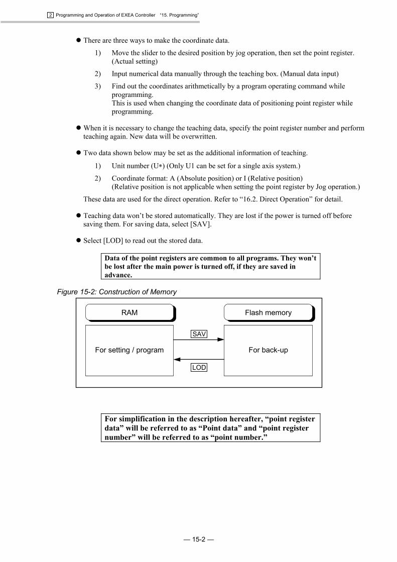
15.2.3.4. Procedure for Copying Program
CPYProgramming Screen
� Program data can be copied to other program (different program number).
� Pressing MODE key terminates to copy data. (Refer to Figure 15-18.)
Figure 15-18: Programming screen (Procedure for copying program)
Press F2 key.
Press F4 key.
: Programming screen 2
: Programming screen 1
Press F4 key.
Copying program
[EDT] 000
1EDT 2prog 4etc
� Copy program data of a selectedprogram to another designatedprogram.
: Program copy screen[EDT] 000
1CLR 2CPY 4etc
[EDT] 000
1SAV 2LOD 4etc
Press F4 key.
Move cursor using keys.Press numeric keys.0 to 9 . Pressing CLR keys changes to 000.
Changing program number by pressing keys.(Possible to input in the screens shown above.)
[EDT] 000
CPY(000>000)?
: Example of program number setting.Source program number: 001Program number to copy: 011
Press SET key.
: Returns to the programming screen 2.
[EDT] 000
CPY(001>011)?
[EDT] 000
1CLR 2CPY 4etc
: Example of program copy� Data of program number 001 are
copied to program number 011.
Select program numberof the source program.(Program to be copied.)Use F1 key.
Select program number to copythe program. Select by F2 key.
Press MODE key.
Press MODE key.
Programmingscreen
2 Programming and Operation of EXEA Controller “15. Programming”
— 15-24 —
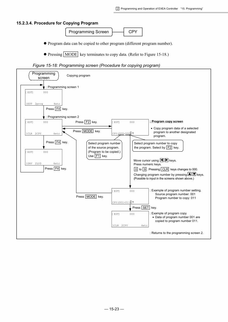
15.2.3.5. Procedure for Saving Program
SAVProgramming Screen
� All program date shall be stored to the flash memory.
Caution : Be sure to store new program or revised program immediately. New orrevised program is lost if the power is turned off before store it.
Caution : “Writing” message appears on the screen while storing the program. Neverturn off the power while storing. Otherwise Memory error alarm will begiven.
Figure 15-19: Programming screen (Procedure for saving program)
Press F4 key.
: Programming screen 3
: Programming screen 1
Press F4 key.
Saving program
[EDT] 000
1EDT 2prog 4etc
� Write all program data to flash memoryfrom RAM.
: Saving program screen
[EDT] 000
1CLR 2CPY 4etc
[EDT] 000
1SAV 2LOD 4etc
Press MODE key.
Press F4 key.
[EDT]S
Push SET
Press SET key.
Caution : Data is being written to flashmemory. Do not turn power off.Otherwise “memory error” alarmarises.
: Returns to the programming screen 3.
: Indicates “Writing”[EDT]S
Writing
(approximately 30 seconds)
Programmingscreen
Press F1 key.[EDT] 000
1SAV 2LOD 4etc
: Programming screen 2

2 Programming and Operation of EXEA Controller “15. Programming”
— 15-25 —
15.2.3.6. Procedure for Reading out Program
LODProgramming screen
� Load program data to RAM from flash memory.
Figure 15-20: Programming screen (Procedure for reading out program)
Press F2 key.
Press F4 key.
: Programming screen 3
: Programming screen 1
Press F4 key.
Read out program
[EDT] 000
1EDT 2prog 4etc
: Program read out screen
� Read out all program data toRAM from flash memory.
[EDT] 000
1CLR 2CPY 4etc
[EDT] 000
1SAV 2LOD 4etc Press MODE key.
Press F4 key.
[EDT]L
Push SET
Press SET key.
: Returns to the programmingscreen 3.
[EDT] 000
1SAV 2LOD 4etc
Programmingscreen
: Programming screen 2

2 Programming and Operation of EXEA Controller “15. Programming”
— 15-26 —
15.2.4. Program Editing Screen
� In the program editing screen, entering name and memos of designated program number arepossible. Copying, deleting and inserting of program command are possible as well.
� Program number and step number may be changed in this editing screen.
15.2.4.1. Procedure for Entering Name of Program
Program editing screen NAM
� Significant digit of program name is 8 figures. This is used for calling a subroutine, changing theoperation program and a multitask operation.
� Press MODE key to cancel the inputs.
Figure 15-21: Program editing screen (Procedure for entering name of program)
<<Explanation of display>>Program Number : 000Program name : EXEAInputted command : 000 (not inputted yet)
Press F2 key.
Press F4 key.
: Program editing screen 1
Press F4 key.
Input name of program
[EDT]E 000/000
1EDT 2NAM MEM 4etc
: Input screen of program name
[EDT]E 000/000
1prog 2step 4etc
[EDT]E 000/000
1CPY 2INS 3DEL 4etc
Press F4 key.
[EDT]EN 000 _
Name
: Example of program nameEXEA is inputted.
Press SET key.
[EDT]EN 000EXEA_
Name
[EDT]E 000/000
1EDT 2NAM 3MEM 4etc
� Inputted program name may beconfirmed. Mark “$” is put on the head ofthe name.
: Returns to the programming screen 1.
: Returns to the program editing screen 1.
Press MODE key.
Press MODE key.
Press MODE key.
[EDT] 000$EXEA (000)
1EDT 2prog 4etc
Program editingscreen
Select letters ( A to Z ) and numbers ( 0 to 9 )using keys and numeric keys.CLR key is to delete inputs. Use keys to move a
figures one place. Eight characters are the maximum.

2 Programming and Operation of EXEA Controller “15. Programming”
— 15-27 —
15.2.4.2. Inputting Memo to Program
Program editing screen MEM
� Significant figure of the memo is 16 figures. Input of the memo does not affect a program. Itmay be used to note the date etc.
� Press MODE key to cancel an input.
Figure 15-22: Program editing screen (Procedure for inputting memo to program)
<< Explanation of screen>>Program Number : 000Program name : EXEAInputted command : 000 (not inputted yet)Program memo : 19980924.
Select letters ( A to Z ) and numbers ( 0 to 9 )using keys and numeric keys.CLR key is to delete inputs. Use keys to move a
figures one place. Sixteen characters are the maximum.
Press F3 key.
Press F4 key.
: Program editing screen 1
Press F4 key.
Inputting program memo
[EDT]E 000/000
1EDT 2NAM 3MEM 4etc
: Inputting program memoscreen
[EDT]E 000/000
1prog 2step 4etc
[EDT]E 000/000
1CPY 2INS 3DEL 4etc
Press F4 key.
[EDT]EM 000 _
Memo
: Example of memo input.Inputted 19980924.
Press SET key.
[EDT]EM 00019980924_
Name
[EDT]E 000/000
1EDT 2NAM 3MEM 4etc
� Confirmation of inputted memo ispossible in this screen.
: Returns to the programming screen 1.
: Returns to the program editing screen 1.
Press MODE key.
Press MODE key.
Press MODE key.
[EDT] 000$EXEA (000)199809241EDT 2prog 4etc
Program editingscreen

2 Programming and Operation of EXEA Controller “15. Programming”
— 15-28 —
15.2.4.3. Procedure for Changing Program Number
Program editing screen prog
� Number of program to be edited may be changed.
� Press MODE to cancel input.
Figure 15-23: Program editing screen (Procedure for changing program number)
Select numbers by numeric keys ( 0 to 9 ) orkeys. Pressing CLR changes to 000.
Press F1 key.
Press F4 key.
: Program editing screen 1
: Program editing screen 2
Press F4 key.
Changing program number
[EDT]E 000/000
1EDT 2NAM 3MEM 4etc
: Screen to change program number[EDT]E 000/000
1prog 2step 4etc
[EDT]E 000/000
1CPY 2INS 3DEL 4etc
Press F4 key.
[EDT]E 000/000
: Example of changeInput 012.
Press SET key.
[EDT]E 012/000
[EDT]E 012/000
1prog 2step 4etc
: Moves to the program editing screen 2.
Press MODE key.
Press MODE key.
Indication of step number
Indication of program number
Program editingscreen

2 Programming and Operation of EXEA Controller “15. Programming”
— 15-29 —
15.2.4.4. Procedure for Changing Step Number
Program editing screen step
� You can change a step number of program to be edited. Changeable number range is from 000 toa number of step to which a program is set.
� Press MODE to cancel input.
Figure 15-24: Program editing screen (Procedure for changing step number)
Select numbers by numeric keys ( 0 to 9 ) orkeys. Pressing CLR changes to 000.
Press F2 key.
Press F4 key.
� Indicates existing program command.(Example: MOV P0000)
: Program editing screen 1
Press F4 key.
: Program editing screen 2
Changing step number (Provided that the program commands are inputted.)
[EDT]E 000/000MOV P0000
1EDT 2NAM 3MEM 4etc
[EDT]E 000/000MOV P0000
1prog 2step 4etc
[EDT]E 000/000MOV P0000
1CPY 2INS 3DEL 4etc
: Screen to change step number
Press F4 key.
[EDT]E 000/000_MOV P0000
: Example of step number changeInput 001.Indicates command in step number 001.(Example: MOV P0000)
Press SET key.
[EDT]E 000/001_MOV P0001
[EDT]E 000/001MOV P0001
1prog 2step 4etc
: Returns to the program editing screen 2.
Press MODE key.
Press MODE key.
Program editingscreen
Changing step number can be carried out in the above screens using keys when the program is set to the step.: Press key.Step number increases. 000 � 001 •••• � 999 (if the programs are set to step 999.): Press key.Step number decreases. 999 � 998 •••• � 000
Indication of program number
Indication of step number

2 Programming and Operation of EXEA Controller “15. Programming”
— 15-30 —
15.2.4.5. Procedure for Copying Program Command
Program editing screen CPY
� You can copy edited program partially to the another part of the same program.
� Press MODE to cancel inputs.
Figure 15-25: Program editing screen (Procedure for copying program command)
Select numbers by numeric keys ( 0 to 9 ) orkeys. Pressing CLR changes to 000.
Press F1 key.
Press F4 key.
� Indicate inputted program command.(Example: MOV P0000)
: Program editing screen 1
Press F4 key.
: Program editing screen 3
Copying program command (Provided that the program commands are inputted.)
[EDT]E 000/000MOV P0000
1EDT 2NAM 3MEM 4etc
[EDT]E 000/000MOV P0000
1prog 2step 4etc
[EDT]E 000/000MOV P0000
1CPY 2INS 3DEL 4etc
: Screen to copy program command
Press F4 key.
[EDT]E 000/000MOV P0000
CPY(000>000/000)?
: Example of copyingTop number of step to be copiedLast number of step to be copied.Top number of step to copy
Press SET key.
[EDT]E 000/000MOV P0000
CPY(000>000/001)?
[EDT]E 000/000MOV P0000
1CPY 2INS 3DEL 4etc
: Returns to the program editing screen 3.
Press MODE key.
Press MODE key.
Program editingscreen
Indicates the top number of stepto be copied. Select by F1 key.
[EDT]E 000/001MOV P0000
1CPY 2INS 3DEL 4etc
<<Confirmation>>Confirms that the copy is made tostep number 001.
Indicates the top step number forcopy. Select by F3 key.
Press key.
: Program editing screen 2
Indicates the last number of stepto be copied. Select by F2 key.
2 Programming and Operation of EXEA Controller “15. Programming”
— 15-31 —
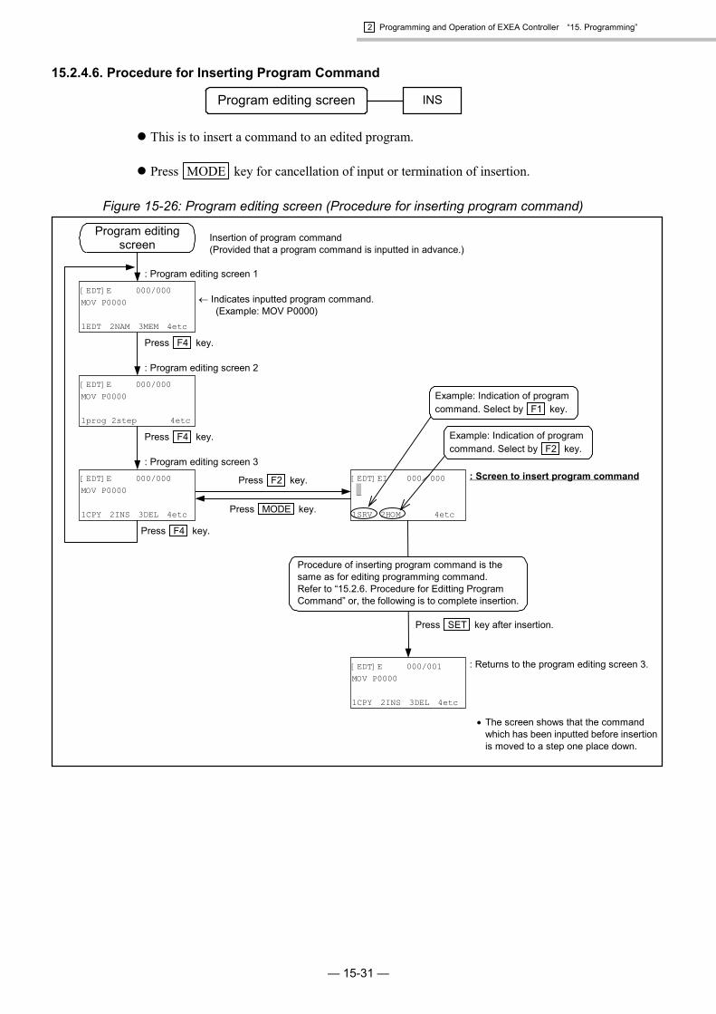
15.2.4.6. Procedure for Inserting Program Command
Program editing screen INS
� This is to insert a command to an edited program.
� Press MODE key for cancellation of input or termination of insertion.
Figure 15-26: Program editing screen (Procedure for inserting program command)
Press F2 key.
Press F4 key.
� Indicates inputted program command.(Example: MOV P0000)
: Program editing screen 1
Press F4 key.
: Program editing screen 3
Insertion of program command(Provided that a program command is inputted in advance.)
[EDT]E 000/000MOV P0000
1EDT 2NAM 3MEM 4etc
[EDT]E 000/000MOV P0000
1prog 2step 4etc
[EDT]E 000/000MOV P0000
1CPY 2INS 3DEL 4etc
: Screen to insert program command
Press F4 key.
[EDT]EI 000/000 _
1SRV 2HOM 4etc
� The screen shows that the commandwhich has been inputted before insertionis moved to a step one place down.
: Returns to the program editing screen 3.
Press SET key after insertion.
[EDT]E 000/001MOV P0000
1CPY 2INS 3DEL 4etc
Press MODE key.
Program editingscreen
Procedure of inserting program command is thesame as for editing programming command.Refer to “15.2.6. Procedure for Editting ProgramCommand” or, the following is to complete insertion.
Example: Indication of programcommand. Select by F2 key.
Example: Indication of programcommand. Select by F1 key.
: Program editing screen 2

2 Programming and Operation of EXEA Controller “15. Programming”
— 15-32 —
15.2.4.7. Procedure for Deleting Program Command
Program editing screen DEL
� This is to delete an edited program command partially.
� Press MODE key to cancel input.
Figure 15-27: Program editing screen (Procedure for deleting program command)
Press F3 key.
Press F4 key.
� Indicating inputted program command. (Example: MOV P0000) Step Command 000 MOVP0000 001 MOVP0001002 MOVP0002
: Program editing screen 1
Press F4 key.
: Program editing screen 3
Deleting program command. (Provided that a program command is inputted in advance.)
[EDT]E 000/000MOV P0000
1EDT 2NAM 3MEM 4etc
[EDT]E 000/000MOV P0000
1prog 2step 4etc
[EDT]E 000/000MOV P0000
1CPY 2INS 3DEL 4etc
: Screen to delete program command
Press F4 key.
[EDT]E 000/000 MOV P000
DEL(000/000)?
: Returns to the program editing screen 3.
: Example of deletionThe top step number to be deleted : 000The last step number to be deleted : 001
� The screen shows that the command of step002 is moved up to step 000 due to thedeletion of step 000 and 001.
[EDT]E 000/000MOV P0002
1CPY 2INS 3DEL 4etc
[EDT]E 000/000MOV P0000
DEL(000/001)?
Press MODE key.
Program editingscreen
Move cursor using keys.Select numbers by numeric keys ( 0 to 9 ) or keys.Pressing CLR changes to 000.
Press SET key.
Indicates the last number of step to be deleted.Select by pressing F2 key or moving cursor.
Indicates the top number of step to be deleted.Select by pressing F1 key or moving cursor.
: Program editing screen 2
PressMODE key.

2 Programming and Operation of EXEA Controller “15. Programming”
— 15-33 —
15.2.5. Editing Program Command
� This section describes editing program command.
� Press MODE key to cancel input.
15.2.5.1. Editing / Setting of Program Command
� Program commands consist of six groups (five groups for a single axis system) of command andselected necessary data from sub-menus accompanied with respective commands.
Figure 15-28: Editing menu list of program command
Editingprogram
: Edits motion commands.
: Edits sequence control commands.
: Edits data control commands.
: Edits palletizing operation commands.
: Edits execution commands for subroutine.
: Edits control commands for operating conditions.
Program commandediting screen 1
Program commandediting screen 2
sts
call
pal
dat
seq
mot
� F4 key scrolls the program command editing screen. In each program command editing screen,
pressing F1 , F2 and F3 keys selects the program command which is designated to each key.
Figure 15-29: Flow of editing screen for program command
F4F4F4
Program command editing screen 2Program command editing screen 1
[EDT]EE 000/000
1pal 2call 3sts 4etc
[EDT]EE 000/000
1mot 2seq 3dat 4etc
Commandselecting screen *
* Part in the dotted lines changes to “1call 2sts” for a single axis system.
*
* In the Command selecting screen, the screen which was selected the last time appears.Motion command editing screen--------------------------------Figure 15-30Sequence control command editing screen -------------------Figure 15-34Data control command editing screen -------------------------Figure 15-37Palletizing motion command editing screen------------------Figure 15-40
(Note) Not available for a single axis system.Subroutine execution command editing screen --------------Figure 15-43Operating condition control command editing screen------Figure 15-46
(Motion command editing screen is selected for the screen just after the power isturned on.)

2 Programming and Operation of EXEA Controller “15. Programming”
— 15-34 —
Figure 15-30: About sub-menu accompanied with respective commands
F4
F1
F1 F4
In program command editing screen 1, pressF1 ‘mot’. (Selects motion command.)
[EDT]EE 000/000
1mot 2seq 3dat 4etc
[EDT]EE 000/000
1pal 2call 3sts 4etc
[EDT]EE 000/000
1SRV 2HOM 4etc
[EDT]EE 000/000
1MOV 2ARC 3CIR 4etc
Select MOV command by pressingF1 key.
[EDT]EE 000/000MOV P000
1U 2P 3& 4etc
Right side from this part iscalled sub-menu. For details,refer to the items of sub-menusin each command.
MOV command is displayed.
*1. Part in the dotted lines is indicated as “1call 2sts” for a single axis system.*2. There won’t be any indication of this part for a single axis system.
*2
*1
Note: Even though the sub-menus are common in each editing screen, the sub-menus you canselect in each command screen differs. Refer to the syntax of respective descriptions in“15.2.7. Description of Program Command” for a sub-menu that is possible to select.Select a sub-menu that is indicated in a syntax as the screen shows other sub-menus thatare not possible to select simultaneously. Otherwise an alarm will arise.

2 Programming and Operation of EXEA Controller “15. Programming”
— 15-35 —
15.2.5.2. List of Program Command
� The program command listed in Table 15-2 are provided for EXEA controller.
Table 15-2: Program command listCommand group Code Function
SRV Servo on/offHOM Home returnMOV Linear interpolation **ARC * Circular arc interpolationCIR * Circular interpolationMSTP Motion stopMEND Wait for end of motionMSTS Check for motion conditionMOVM Continuous linear interpolationCPS * Start continue path ** (multi-point)
mot Motion command
CPE * Complete continue path’ Set comment line
END End of programTAG Set labelCMP Compare data (with jump)JMP Unconditional jumpJEQ Conditional jump (=)JGE Conditional jump (�)JLE Conditional jump (�)JNE Conditional jump (�)JGT Conditional jump (>)JLT Conditional jump (<)TIM Set timerWAIT Hold sequenceREP Repetition set
seq Sequence control command
NXT Repetition endLD Set dataCAL Calculate dataTCH Set current dataOUT I/O outputINP I/O input
dat Data control command
LCAL Data logical operationPALI * Initialize palletizingPALL * Call subroutine for pallet changePALE * Call subroutine for pallet changePALM * Move pallet positionPALN * Change pallet position number
pal Palletizing motion command
QSTS * Conform palletizing conditionCALL Subroutine call, startRET Subroutine call, endRSTA Initialize resuming operation settingCHG Switch operation programCHLD Start sub-sequence execution
call Subroutine command
ENDC End sub-sequence executionUNT Set moving unit (Do not use in a single axis system.)SPD Set motion speed and accelerationTYP Set motion formatNOF Set shift value of point register numberPBS Set position of working reference pointESCZ * Set off-limits area of Z axis
sts Edit operational conditioncommand
LDS Read out, system setting state
* Not available for a single axis system.** Linear interpolation is converted to “linear motion” in a single axis system.
2 Programming and Operation of EXEA Controller “15. Programming”
— 15-36 —
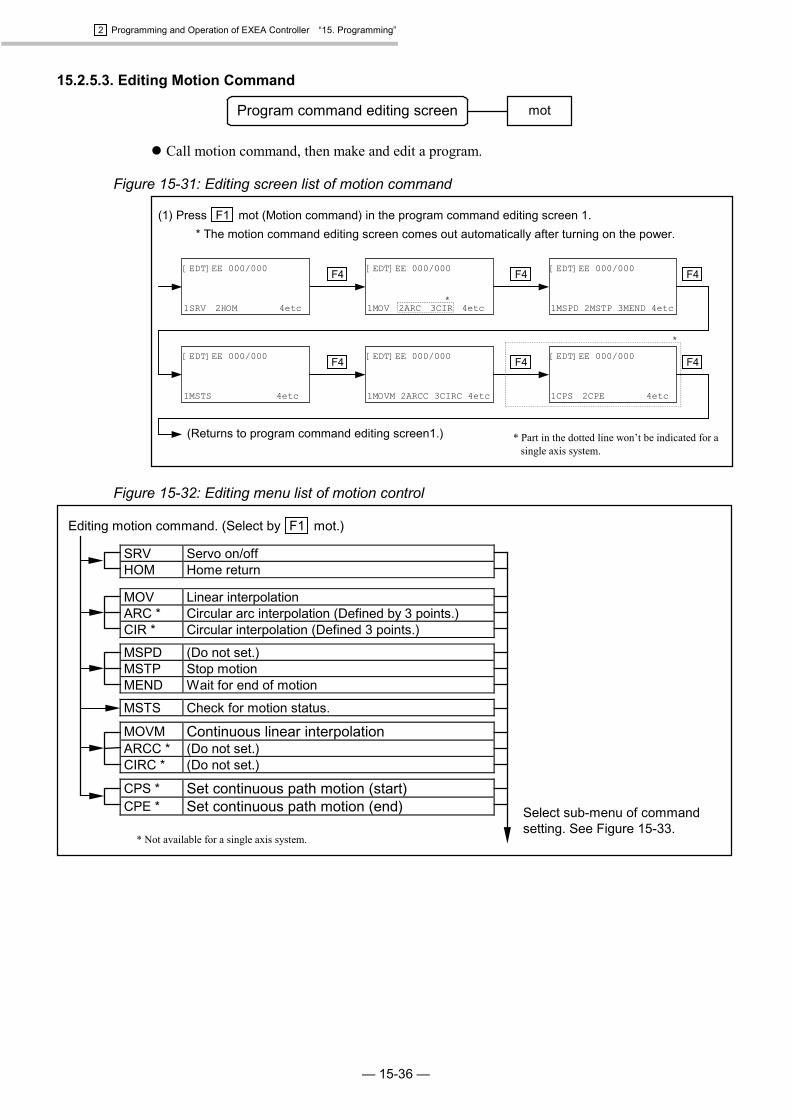
15.2.5.3. Editing Motion Command
Program command editing screen mot
� Call motion command, then make and edit a program.
Figure 15-31: Editing screen list of motion command
F4F4F4
(1) Press F1 mot (Motion command) in the program command editing screen 1.* The motion command editing screen comes out automatically after turning on the power.
(Returns to program command editing screen1.)
[EDT]EE 000/000
1MSTS 4etc
[EDT]EE 000/000
1MSPD 2MSTP 3MEND 4etc
[EDT]EE 000/000
1MOV 2ARC 3CIR 4etc
[EDT]EE 000/000
1SRV 2HOM 4etc
[EDT]EE 000/000
1CPS 2CPE 4etc
[EDT]EE 000/000
1MOVM 2ARCC 3CIRC 4etc
F4F4 F4
* Part in the dotted line won’t be indicated for asingle axis system.
*
*
Figure 15-32: Editing menu list of motion control
Editing motion command. (Select by F1 mot.)
Select sub-menu of commandsetting. See Figure 15-33.
SRV Servo on/offHOM Home return
MOV Linear interpolationARC * Circular arc interpolation (Defined by 3 points.)CIR * Circular interpolation (Defined 3 points.)
MSPD (Do not set.)MSTP Stop motionMEND Wait for end of motion
MSTS Check for motion status.
MOVM Continuous linear interpolationARCC * (Do not set.)CIRC * (Do not set.)
CPS * Set continuous path motion (start)CPE * Set continuous path motion (end)
* Not available for a single axis system.

2 Programming and Operation of EXEA Controller “15. Programming”
— 15-37 —
Figure 15-33: Sub-menu list of motion command editing
F4etc
U U@D Unit number, specify direct/indirectP P@D Point number, specify direct/indirect& Specify motion format
Xp Xp@D Point of X axis, specify direct/indirectXs Xs@D Condition of X axis, specify direct/indirectX Specify X axis
Yp * Yp@D Point of Y axis, specify direct/indirectYs * Ys@D Condition of Y axis, specify direct/indirectY * Specify Y axis
Zp * Zp@D Point of Z axis, specify direct/indirectZs * Zs@D Condition of Z axis, specify direct/indirectZ * Specify Z axis
Rp * Rp@D Point of R axis, specify direct/indirectRs * Rs@D Condition of R axis, specify direct/indirectR * Specify R axis
S S@D Motion speed, specify direct/indirectA A@D Motion acceleration, specify direct/indirectB B@D Motion deceleration, specify direct/indirect
SR SR@D Motion speed, specify direct/indirect (in % )AR AR@D Motion acceleration, specify direct/indirect (in %)BR BR@D Motion deceleration, specify direct/indirect (in %)
D Specify number of data register.# Numeric number setting (whole number)= Sign (equal sign)
OFF OffON OnALL Setting all axis / all unit
CUR Set current position to Home position.RSTA Initialize re-start setting after power is turn on again.
ins Insert sub-menu.del Delete one letterchg Select direct / indirect setting
* Not available for a single axis system.

2 Programming and Operation of EXEA Controller “15. Programming”
— 15-38 —
15.2.5.4. Editing Sequence Control Command
Program command editing screen seq
� Call all sequence control commands, then make and edit program.
Figure 15-34: Editing screen list of sequence control command
F4F4F4
Press F2 seq (Sequence control command) in the program command editing screen.
(Returns to the program commad editing screen 1.)
[EDT]EE 000/000
1JNE 2JGT 3JLT 4etc
[EDT]EE 000/000
1JEQ 2JGE 3JLE 4etc
[EDT]EE 000/000
1TAG 2CMP 3JMP 4etc
[EDT]EE 000/000
1’ 2END 4etc
[EDT]EE 000/000
1REP 2NXT 4etc
[EDT]EE 000/000
1TIM 2WAIT 4etc
F4F4 F4
Figure 15-35: Editing menu list: Sequence control command
(2) Edit sequence control. (Select by F2 seq.)
Select sub-menu for commandsetting. See Figure 15-36.
’ Set comment line.END End of programmed operation
TAG Set labelCMP Compare data (with jump)JMP Jump
JEQ Conditional jump (=)JGE Conditional jump (�)JLE Conditional jump (�)
JNE Conditional jump (�)JGT Conditional jump (>)JLT Conditional jump (<)
TIM Timer settingWAIT Hold sequence
REP Repetition (start)NXT Repetition (end)
2 Programming and Operation of EXEA Controller “15. Programming”
— 15-39 —
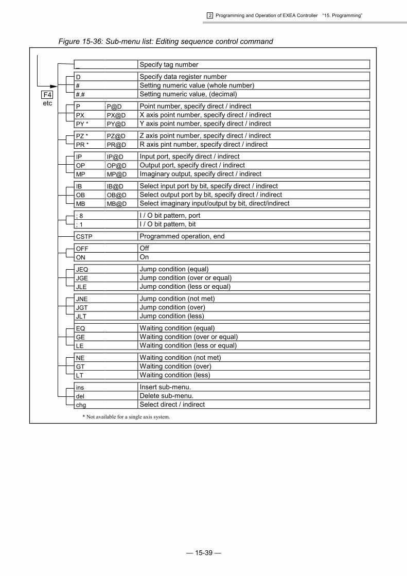
Figure 15-36: Sub-menu list: Editing sequence control command
F4etc
_ Specify tag number
D Specify data register number# Setting numeric value (whole number)#.# Setting numeric value, (decimal)
P P@D Point number, specify direct / indirectPX PX@D X axis point number, specify direct / indirectPY * PY@D Y axis point number, specify direct / indirect
PZ * PZ@D Z axis point number, specify direct / indirectPR * PR@D R axis pint number, specify direct / indirect
IP IP@D Input port, specify direct / indirectOP OP@D Output port, specify direct / indirectMP MP@D Imaginary output, specify direct / indirect
IB IB@D Select input port by bit, specify direct / indirectOB OB@D Select output port by bit, specify direct / indirectMB MB@D Select imaginary input/output by bit, direct/indirect
; 8 I / O bit pattern, port; 1 I / O bit pattern, bit
CSTP Programmed operation, end
OFF OffON On
JEQ Jump condition (equal)JGE Jump condition (over or equal)JLE Jump condition (less or equal)
JNE Jump condition (not met)JGT Jump condition (over)JLT Jump condition (less)
EQ Waiting condition (equal)GE Waiting condition (over or equal)LE Waiting condition (less or equal)
NE Waiting condition (not met)GT Waiting condition (over)LT Waiting condition (less)
ins Insert sub-menu.del Delete sub-menu.chg Select direct / indirect
* Not available for a single axis system.
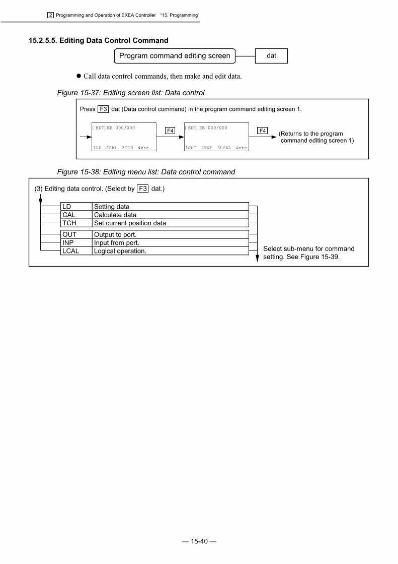
2 Programming and Operation of EXEA Controller “15. Programming”
— 15-40 —
15.2.5.5. Editing Data Control Command
Program command editing screen dat
� Call data control commands, then make and edit data.
Figure 15-37: Editing screen list: Data control
F4F4
Press F3 dat (Data control command) in the program command editing screen 1.
(Returns to the programcommand editing screen 1)
[EDT]EE 000/000
1OUT 2INP 3LCAL 4etc
[EDT]EE 000/000
1LD 2CAL 3TCH 4etc
Figure 15-38: Editing menu list: Data control command
(3) Editing data control. (Select by F3 dat.)
Select sub-menu for commandsetting. See Figure 15-39.
LD Setting dataCAL Calculate dataTCH Set current position data
OUT Output to port.INP Input from port.LCAL Logical operation.

2 Programming and Operation of EXEA Controller “15. Programming”
— 15-41 —
Figure 15-39: Sub-menu list: Editing data control command
F4etc
D Specify data register number# Setting numeric value (whole number)#.# Setting numeric value, (decimal)
U U@D Unit number, specify direct / indirectP P@D Point number, specify direct / indirectPX PX@D X axis point number, specify direct / indirect
PY * PY@D Y axis point number, specify direct / indirectPZ * PZ@D Z axis point number, specify direct / indirectPR * PR@D R axis point number, specify direct / indirect
Xp Xp@D X axis point, specify direct / indirectXs Xs@D Switch of X axis, specify direct / indirect
Yp * Yp@D Y axis point, specify direct / indirectYs * Ys@D Switch of Y axis, specify direct / indirect
Zp * Zp@D Z axis point, specify direct / indirectZs * Zs@D Switch of Z axis, specify direct / indirect
Rp * Rp@D R axis point, specify direct / indirectRs * Rs@D Switch of R axis, specify direct / indirect
IP IP@D Selection of Input port, specify direct / indirectOP OP@D Selection of Output port, specify direct / indirectMP MP@D Imaginary output, specify direct / indirect
IB IB@D Select input port by bit, specify direct / indirectOB OB@D Select output port by bit, specify direct / indirectMB MB@D Select imaginary input/output by bit, direct/indirect
; 8 Specify bit pattern of I / O port; 1 Select bit pattern of I / O bit
= Sign (equal)+ Sign (addition)- Sign (subtraction)
* Sign (multiplication)/ Sign (division)% Sign (percent)
OFF OffON OnREV Reverse output condition
OR Logical sumAND Logical multiplicationXOR Exclusive OR
RSTA Return to former state / condition
ins Insert sub-menu.del Delete sub-menu.chg Select direct / indirect
* Not available for a single axis system.

2 Programming and Operation of EXEA Controller “15. Programming”
— 15-42 —
15.2.5.6. Editing Palletizing Motion Command (Multi-axis Combination only.)
Program command editing screen pal
� Call palletizing motion command, then make and edit the program.
Figure 15-40: Editing screen list: Palletizing operation command
F4F4
Press F1 pal (Palletizing motion command) in the program command editing screen 2.
(Returns the program commandediting screen 1. )
[EDT]EE 000/000
1PALM 2PALN 3QSTS 4etc
[EDT]EE 000/000
1PALI 2PALL 3PALE 4etc
Figure 15-41: Editing menu list: Palletizing operation command
(4) Edit palletizing operation command. (Select by F1 pal.)
Select sub-menu for commandsetting. See Figure 15-42.
PALI Initialize palletizing operation.PALL Call subroutine, changing palletPALE Call subroutine, changing pallet
PALM Move pallet positionPALN Change palletizing pattern numberQSTS Confirm condition of the palletizing
Figure 15-42: Editing sub-menu list: Palletizing operation command
F4etc
QN QN@D Palletizing operation number, specify direct / indirectQP QP@D Palletizing pattern number, specify direct / indirect
U U@D Unit number, specify direct / indirectP P@D Point number, specify direct / indirect& Specify motion format.
D Specify data register number.# Numeric value (whole number)
_ Specify tag number.$ Specify name of program or pallet.
S S@D Motion speed, specify direct / indirectA A@D Motion acceleration, specify direct / indirectB B@D Motion deceleration, specify direct / indirect
SR SR@D Motion speed (%), specify direct / indirectAR AR@D Motion acceleration (%), specify direct / indirectBR BR@D Motion deceleration (%), specify direct / indirect
= Sign (equal)
QPM Total number of points for palletQPC Next point number of palletizing operation
ins Insert sub-menu.del Delete one letter.chg Selection of direct /indirect.
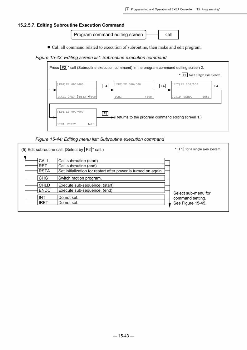
2 Programming and Operation of EXEA Controller “15. Programming”
— 15-43 —
15.2.5.7. Editing Subroutine Execution Command
Program command editing screen call
� Call all command related to execution of subroutine, then make and edit program,
Figure 15-43: Editing screen list: Subroutine execution command
F4F4F4
Press F2 * call (Subroutine execution command) in the program command editing screen 2.
(Returns to the program command editing screen 1.)[EDT]EE 000/000
1INT 2IRET 4etc
[EDT]EE 000/000
1CHLD 2ENDC 4etc
[EDT]EE 000/000
1CHG 4etc
[EDT]EE 000/000
1CALL 2RET 3RSTA 4etc
F4
* F1 for a single axis system.
Figure 15-44: Editing menu list: Subroutine execution command
(5) Edit subroutine call. (Select by F2 * call.)
Select sub-menu forcommand setting.See Figure 15-45.
CALL Call subroutine (start)RET Call subroutine (end)RSTA Set initialization for restart after power is turned on again.
CHG Switch motion program.
CHLD Execute sub-sequence. (start)ENDC Execute sub-sequence. (end)
INT Do not set.IRET Do not set.
* F1 for a single axis system.

2 Programming and Operation of EXEA Controller “15. Programming”
— 15-44 —
Figure 15-45: Sub-menu list: Editing subroutine execution command
F4etc
D Specify data register number# Setting numeric value (whole number)#.# Setting numeric value, (decimal)
P P@D Point number, specify direct / indirectPX PX@D X axis point number, specify direct / indirectPY * PY@D Y axis point number, specify direct / indirect
PZ * PZ@D Z axis point number, specify direct / indirectPR * PR@D R axis pint number, specify direct / indirect
_ Specify tag number.$ Specify name of program or pallet.
IP IP@D Input port, specify direct / indirectOP OP@D Output port, specify direct / indirectMP MP@D Imaginary output, specify direct / indirect
IB IB@D Select input port by bit, specify direct / indirectOB OB@D Select output port by bit, specify direct / indirectMB MB@D Select imaginary input/output by bit (every bit) direct/indirect
; 8 I / O bit pattern, port; 1 I / O bit pattern, bit
OFF OffON On
CSTP Cycle stopDSTP Decelerating stopSTP Immediate stop
DIS Prohibit interruptionENA Permit interruption
EQ Interruption condition, (equal)GE Interruption condition, (more or equal)LE Interruption condition, (less or equal)
NE Interruption condition, (non conformity)GT Interruption condition, (more)LT Interruption condition, (less)
ins Insert sub-menu.del Delete sub-menu.chg Select indirect or indirect.
* Not available for a single axis system.

2 Programming and Operation of EXEA Controller “15. Programming”
— 15-45 —
15.2.5.8. Command for Operating Condition Control
Program command editing screen sts
� Sets or reads out operating conditions.
Figure 15-46: Editing screen list: Operating condition control command
F4F4F4
Press F3 sts (Operating condition control command) key in the program command editing screen 2.(Command for operating condition)
(Returns to program commandediting screen 1.)
[EDT]EE 000/000
1PDSV 4etc
[EDT]EE 000/000
1ESCZ 2ESCR 4etc
[EDT]EE 000/000
1NOF 2PBS 4etc
[EDT]EE 000/000
1UNT 2SPD 3TYP 4etc
F4F4 [EDT]EE 000/000
1LDS 4etc
*1. F2 for a single axis system.
*2. Not indicated in case of a single axis system.
*1
*2
Figure 15-47: Command menu list: Operating condition control command
(6) Edit operating condition. (Select by F3 sts key.)
Select sub-menu for command ofoperating condition.See Figure 15-48.
UNT Set operating unit.SPD Set motion speed and acceleration / deceleration.TYP Set motion format.
NOF Set off-set value of point register number.PBS Position of working reference point
ESCZ *2 Off-limits area, Z axis motionESCR *2 Off-limits area, R axis motion (Do not set.)
PDSV Save operating condition. (Reserved)
LDS Read out motion setting data.
*1. F2 for a single axis system.
*2. Not indicated in case of a single axis system.
*1
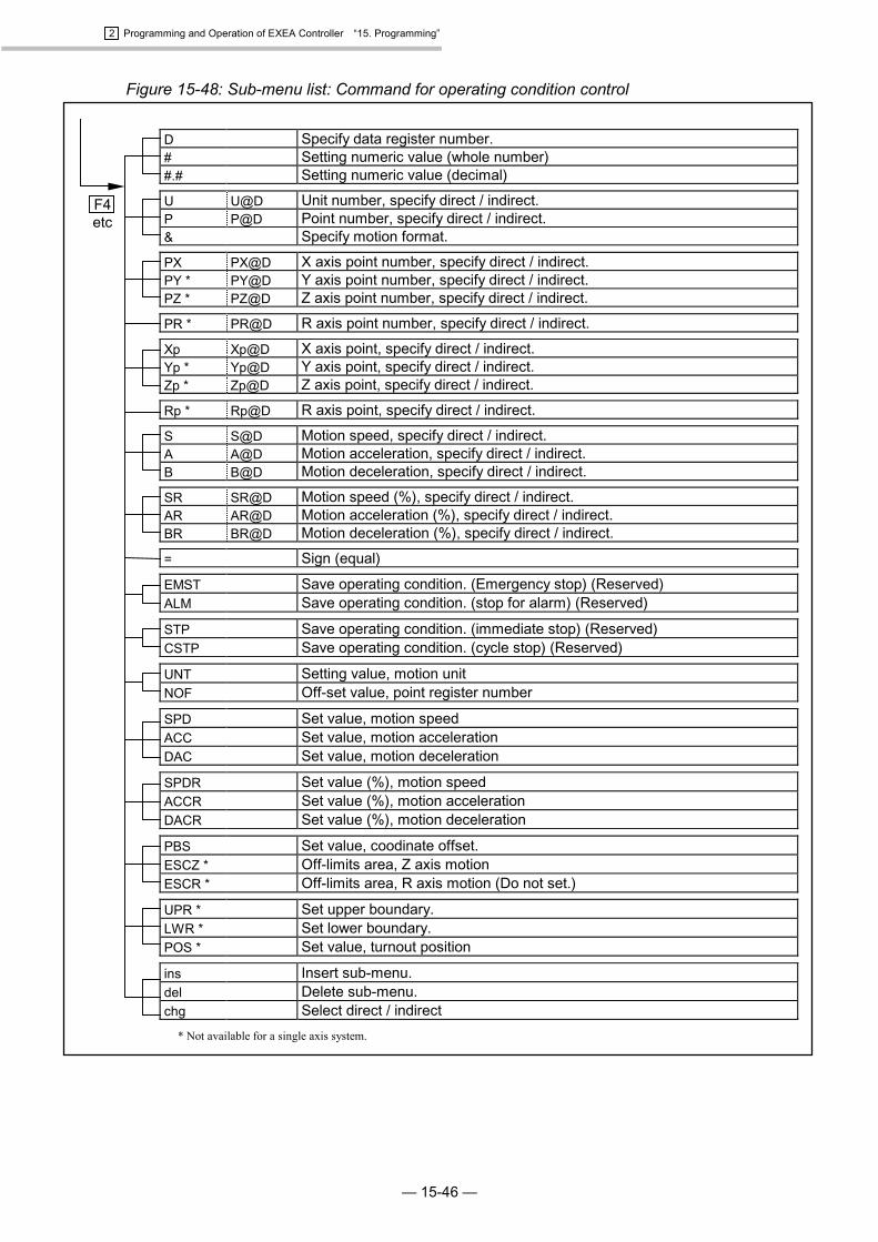
2 Programming and Operation of EXEA Controller “15. Programming”
— 15-46 —
Figure 15-48: Sub-menu list: Command for operating condition control
F4etc
D Specify data register number.# Setting numeric value (whole number)#.# Setting numeric value (decimal)
U U@D Unit number, specify direct / indirect.P P@D Point number, specify direct / indirect.& Specify motion format.
PX PX@D X axis point number, specify direct / indirect.PY * PY@D Y axis point number, specify direct / indirect.PZ * PZ@D Z axis point number, specify direct / indirect.
PR * PR@D R axis point number, specify direct / indirect.
Xp Xp@D X axis point, specify direct / indirect.Yp * Yp@D Y axis point, specify direct / indirect.Zp * Zp@D Z axis point, specify direct / indirect.
Rp * Rp@D R axis point, specify direct / indirect.
S S@D Motion speed, specify direct / indirect.A A@D Motion acceleration, specify direct / indirect.B B@D Motion deceleration, specify direct / indirect.
SR SR@D Motion speed (%), specify direct / indirect.AR AR@D Motion acceleration (%), specify direct / indirect.BR BR@D Motion deceleration (%), specify direct / indirect.
= Sign (equal)
EMST Save operating condition. (Emergency stop) (Reserved)ALM Save operating condition. (stop for alarm) (Reserved)
STP Save operating condition. (immediate stop) (Reserved)CSTP Save operating condition. (cycle stop) (Reserved)
UNT Setting value, motion unitNOF Off-set value, point register number
SPD Set value, motion speedACC Set value, motion accelerationDAC Set value, motion deceleration
SPDR Set value (%), motion speedACCR Set value (%), motion accelerationDACR Set value (%), motion deceleration
PBS Set value, coodinate offset.ESCZ * Off-limits area, Z axis motionESCR * Off-limits area, R axis motion (Do not set.)
UPR * Set upper boundary.LWR * Set lower boundary.POS * Set value, turnout position
ins Insert sub-menu.del Delete sub-menu.chg Select direct / indirect
* Not available for a single axis system.
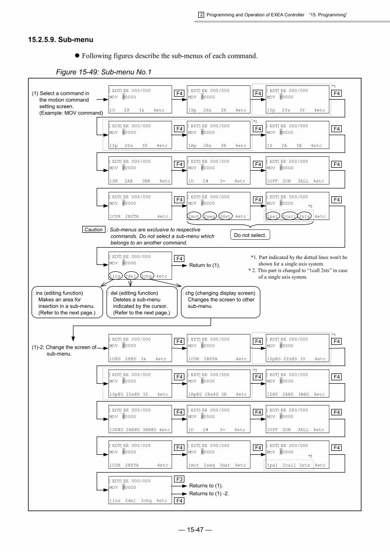
2 Programming and Operation of EXEA Controller “15. Programming”
— 15-47 —
15.2.5.9. Sub-menu
� Following figures describe the sub-menus of each command.
Figure 15-49: Sub-menu No.1
(1) Select a command inthe motion commandsetting screen.(Example: MOV command)
: ins (editing function)Makes an area forinsertion in a sub-menu.(Refer to the next page.)
: del (editing function)Deletes a sub-menuindicated by the cursor.(Refer to the next page.)
: chg (changing display screen)Changes the screen to othersub-menu.
[EDT]EE 000/000MOV P0000
1CUR 2RSTA 4etc
F4
[EDT]EE 000/000MOV P0000
1OFF 2ON 3ALL 4etc
F4
[EDT]EE 000/000MOV P0000
1D 2# 3= 4etc
F4
[EDT]EE 000/000MOV P0000
1SR 2AR 3BR 4etc
F4
Return to (1).
Do not select.
F4
[EDT]EE 000/000MOV P0000
1Zp 2Zs 3Z 4etc
[EDT]EE 000/000MOV P0000
1Yp 2Ys 3Y 4etc
[EDT]EE 000/000MOV P0000
1mot 2seq 3dat 4etc
[EDT]EE 000/000MOV P0000
1Xp 2Xs 3X 4etc
[EDT]EE 000/000MOV P0000
1U 2P 3& 4etc
F4F4 [EDT]EE 000/000MOV P0000
1Rp 2Rs 3R 4etc
*1. Part indicated by the dotted lines won't beshown for a single axis system.
* 2. This part is changed to “1call 2sts” in caseof a single axis system.
F4
*1
F4
F4[EDT]EE 000/000MOV P0000
1S 2A 3B 4etc
F4F4
[EDT]EE 000/000MOV P0000
1pal 2call 3sts 4etc
Caution : Sub-menus are exclusive to respectivecommands. Do not select a sub-menu whichbelongs to an another command.
[EDT]EE 000/000MOV P0000
1ins 2del 3chg 4etc
F4
*2
*1
(1)-2: Change the screen ofsub-menu.
[EDT]EE 000/000MOV P0000
1CUR 2RSTA 4etc
F4
[EDT]EE 000/000MOV P0000
1OFF 2ON 3ALL 4etc
F4
[EDT]EE 000/000MOV P0000
1D 2# 3= 4etc
F4
[EDT]EE 000/000MOV P0000
1SR@D 2AR@D 3BR@D 4etc
F4
Returns to (1).
F4
[EDT]EE 000/000MOV P0000
1Zp@D 2Zs@D 3Z 4etc
[EDT]EE 000/000MOV P0000
1Yp@D 2Ys@D 3Y 4etc
[EDT]EE 000/000MOV P0000
1mot 2seq 3dat 4etc
[EDT]EE 000/000MOV P0000
1CUR 2RSTA 4etc
[EDT]EE 000/000MOV P0000
1U@D 2P@D 3& 4etc
F4F4 [EDT]EE 000/000MOV P0000
1Rp@D 2Rs@D 3R 4etc
F4
*1
F4
F4[EDT]EE 000/000MOV P0000
1S@D 2A@D 3B@D 4etc
F4F4
[EDT]EE 000/000MOV P0000
1pal 2call 3sts 4etc
[EDT]EE 000/000MOV P0000
1ins 2del 3chg 4etc
F3
*2
*1
Returns to (1) -2.F4

2 Programming and Operation of EXEA Controller “15. Programming”
— 15-48 —
Figure 15-50: Sub-menu (No.2)
: Editing functionIt has editing function of insertion/deletion and switchingindication of sub-menu.
Press F1 key.
Press F4 key.
Press F1 key.
Press F2 key.
[EDT]EE 000/000MOV _P0000
1ins 2del 3chg 4etc
[EDT]EE 000/000MOV _P0000
1U 2P 3& 4etc
An insertion area is secured.Select and set a sub-menu tothe area. An example ofinserting unit setting is shownbelow.
Sub-menu is deleted. Selectand set a sub-menu in thespace.
[EDT]EE 000/000MOV _
1ins 2del 3chg 4etc
[EDT]EE 000/000MOV U1 P0000
1U 2P 3& 4etc
: ins (editing function)Makes an area for insertionin a sub-menu.
: del (editing function)Deletes sub-menu indicatedby the cursor.
: chg (changing display screen)Change indication to theother sub-menu.
[EDT]EE 000/000MOV P0000
1ins 2del 3chg 4etc

2 Programming and Operation of EXEA Controller “15. Programming”
— 15-49 —
Figure 15-51: Sub-menu (No.3)
F4F4
F4F4
F4F4
F4F4
F4
*1
F4F4
(2) Select command in thesequence control settingscreen.(Example: TIM command)
[EDT]EE 000/000TIM #0000.00
1NE 2GT 3LT 4etc
F4
[EDT]EE 000/000TIM #0000.00
1OFF 2ON 4etc
[EDT]EE 000/000TIM #0000.00
1CSTP 4etc
[EDT]EE 000/000TIM #0000.00
1IB 2OB 3MB 4etc
Returns to (2).
[EDT]EE 000/000TIM #0000.00
1PZ 2PR 4etc
[EDT]EE 000/000TIM #0000.00
1P 2PX 3PY 4etc
[EDT]EE 000/000TIM #0000.00
1mot 2seq 3dat 4etc
[EDT]EE 000/000TIM #0000.00
1D 2# 3#.# 4etc
[EDT]EE 000/000TIM #0000.00
1_ 4etc
[EDT]EE 000/000TIM #0000.00
1IP 2OP 3MP 4etc
*1. Part indicated by the dotted lines won't beshown for a single axis system.
* 2. This part is changed to “1call 2sts” in caseof a single axis system.
F4
F4
F4[EDT]EE 000/000TIM #0000.00
1IB 2OB 3MB 4etc
[EDT]EE 000/000TIM #0000.00
1pal 2call 3sts 4etc
[EDT]EE 000/000TIM #0000.00
1ins 2del 3chg 4etc F3
*2
(2)-2: Change the screenof sub-menu.
Returns to (2).[EDT]EE 000/000TIM #0000.00
1ins 2del 3chg 4etc
F3
Returns to (2)-2.F4
*1
[EDT]EE 000/000TIM #0000.00
1EQ 2GE 3LE 4etc
[EDT]EE 000/000TIM #0000.00
1JNE 2JGT 3JLT 4etc
[EDT]EE 000/000TIM #0000.00
1JEQ 2JGE 3JLE 4etc
F4
[EDT]EE 000/000TIM #0000.00
1NE 2GT 3LT 4etc
F4
[EDT]EE 000/000TIM #0000.00
1OFF 2ON 4etc
F4
[EDT]EE 000/000TIM #0000.00
1CSTP 4etc
F4
[EDT]EE 000/000TIM #0000.00
1;8 2;1 4etc
F4F4
[EDT]EE 000/000TIM #0000.00
1PZ@D 2PR@D 4etc
[EDT]EE 000/000TIM #0000.00
1P@D 2PX@D 3PY@D 4etc
[EDT]EE 000/000TIM #0000.00
1mot 2seq 3dat 4etc
[EDT]EE 000/000TIM #0000.00
1D 2# 3#.# 4etc
[EDT]EE 000/000TIM #0000.00
1_ 4etc
F4F4 [EDT]EE 000/000TIM #0000.00
1IP@D 2OP@D 3MP@D 4etc
F4
F4
F4[EDT]EE 000/000TIM #0000.00
1IB@D 2OB@D 3MB@D 4etc
F4F4
[EDT]EE 000/000TIM #0000.00
1pal 2call 3sts 4etc
*1
*1
[EDT]EE 000/000TIM #0000.00
1EQ 2GE 3LE 4etc
[EDT]EE 000/000TIM #0000.00
1JNE 2JGT 3JLT 4etc
[EDT]EE 000/000TIM #0000.00
1JEQ 2JGE 3JLE 4etc
F4
F4F4
*2

2 Programming and Operation of EXEA Controller “15. Programming”
— 15-50 —
Figure 15-52: Sub-menu (No. 4)
F4
F4
F4
F4
F4
F4
F4
F4
F4
F4
*1
F4F4
F4F4
F4F4
F4F4
F4F4
*1
[EDT]EE 000/000OUT OP00 = ;0000000
>1pal 2call 3sts 4etc
*2
(3) Select a command in thedata control settingscreen.(Example: OUT command)
[EDT]EE 000/000OUT OP00 = ;0000000
>1OFF 2ON 3REV 4etc
F4
[EDT]EE 000/000OUT OP00 = ;0000000
>1IB 2OB 3MB 4etc
[EDT]EE 000/000OUT OP00 = ;0000000
>1IP 2OP 3MP 4etc
[EDT]EE 000/000OUT OP00 = ;0000000
>1Rp 2Rs 4etc
Returns to (3).
[EDT]EE 000/000OUT OP00 = ;0000000
>1Xp 2Xs 4etc
[EDT]EE 000/000OUT OP00 = ;0000000
>1PY 2PZ 3PR 4etc
[EDT]EE 000/000OUT OP00 = ;0000000
>1OR 2AND 3XOR 4etc
[EDT]EE 000/000OUT OP00 = ;0000000
>1U 2P 3PX 4etc
[EDT]EE 000/000OUT OP00 = ;0000000
>1D 2# 3#.# 4etc
[EDT]EE 000/000OUT OP00 = ;0000000
>1Yp 2Ys 4etc
*1. Part indicated by the dotted lines won't be shown for a single axis system.* 2. This part is changed to “1call 2sts” in case of a single axis system.
F4
F4
F4[EDT]EE 000/000OUT OP00 = ;0000000
>1Zp 2Zs 4etc
[EDT]EE 000/000OUT OP00 = ;0000000
>1RSTA 4etc
[EDT]EE 000/000OUT OP00 = ;0000000
>1mot 2seq 3dat 4etc F3
F4
*1
(3)-2: Change the screenof sub-menu.
[EDT]EE 000/000OUT OP00 = ;0000000
>1* 2/ 3% 4etc
[EDT]EE 000/000OUT OP00 = ;0000000
>1= 2+ 3- 4etc
[EDT]EE 000/000OUT OP00 = ;0000000
>1;8 2;1 4etc
F4
*1
F4F4 [EDT]EE 000/000OUT OP00 = ;0000000
>1ins 2del 3chg 4etc
[EDT]EE 000/000OUT OP00 = ;0000000
>1pal 2call 3sts 4etc
*2
[EDT]EE 000/000OUT OP00 = ;0000000
>1OFF 2ON 3REV 4etc
F4
[EDT]EE 000/000OUT OP00 = ;0000000
>1IB@D 2OB@D 3MB@D 4etc
[EDT]EE 000/000OUT OP00 = ;0000000
>1IP@D 2OP@D 3MP@D 4etc
[EDT]EE 000/000OUT OP00 = ;0000000
>1Rp@D 2Rs@D 4etc
Returns to (3)-2.
Returns to (3).
[EDT]EE 000/000OUT OP00 = ;0000000
>1Xp@D 2Xs@D 4etc
[EDT]EE 000/000OUT OP00 = ;0000000
>1PY@D 2PZ@D 3PR@D 4etc
[EDT]EE 000/000OUT OP00 = ;0000000
>1OR 2AND 3XOR 4etc
[EDT]EE 000/000OUT OP00 = ;0000000
>1U@D 2P@D 3PX@D 4etc
[EDT]EE 000/000OUT OP00 = ;0000000
>1D 2# 3#.# 4etc
[EDT]EE 000/000OUT OP00 = ;0000000
>1Yp@D 2Ys@D 4etc
F4
F4
F4[EDT]EE 000/000OUT OP00 = ;0000000
>1Zp@D 2Zs@D 4etc
[EDT]EE 000/000OUT OP00 = ;0000000
>1RSTA 4etc
[EDT]EE 000/000OUT OP00 = ;0000000
>1mot 2seq 3dat 4etc F3
F4
*1
[EDT]EE 000/000OUT OP00 = ;0000000
>1* 2/ 3% 4etc
[EDT]EE 000/000OUT OP00 = ;0000000
>1= 2+ 3- 4etc
[EDT]EE 000/000OUT OP00 = ;0000000
>1;8 2;1 4etc
F4
*1
F4F4 [EDT]EE 000/000OUT OP00 = ;0000000
>1ins 2del 3chg 4etc

2 Programming and Operation of EXEA Controller “15. Programming”
— 15-51 —
Figure 15-53: Sub-menu (No.5) (Mulit-axis combination only)
F3
F4F4
F4F4
F4
F4F4
F4
F4F4
F4F4
F4F4
F4F4
(4) Select a command in thepalletizing motioncommand setting screen. (Example: PALI)
F4
[EDT]EE 000/000PALI QN00 #0000
1mot 2seq 3dat 4etc
[EDT]EE 000/000PALI QN00 #0000
1QPM 2QPC 4etc
[EDT]EE 000/000PALI QN00 #0000
1= 4etc
Returns to (4).
[EDT]EE 000/000PALI QN00 #0000
1_ 2$ 4etc
[EDT]EE 000/000PALI QN00 #0000
1D 2# 4etc
[EDT]EE 000/000PALI QN00 #0000
1U 2P 3& 4etc
[EDT]EE 000/000PALI QN00 #0000
1QN 2QP 4etc
[EDT]EE 000/000PALI QN00 #0000
1S 2A 3B 4etc
F4[EDT]EE 000/000PALI QN00 #0000
1SR 2AR 3BR 4etc
[EDT]EE 000/000PALI QN00 #0000
1ins 2del 3chg 4etc F3
(4)-2 Change the screen ofsub-menu.
Returns to (4).Returns to (4)-2.
F4
[EDT]EE 000/000PALI QN00 #0000
1pal 2call 3sts 4etc
F4
[EDT]EE 000/000PALI QN00 #0000
1mot 2seq 3dat 4etc
[EDT]EE 000/000PALI QN00 #0000
1QPM 2QPC 4etc
[EDT]EE 000/000PALI QN00 #0000
1= 4etc
[EDT]EE 000/000PALI QN00 #0000
1_ 2$ 4etc
[EDT]EE 000/000PALI QN00 #0000
1D 2# 4etc
[EDT]EE 000/000PALI QN00 #0000
1U@D 2P@D 3& 4etc
[EDT]EE 000/000PALI QN00 #0000
1QN@D 2QP@D 4etc
[EDT]EE 000/000PALI QN00 #0000
1S@D 2A@D 3B@D 4etc
F4[EDT]EE 000/000PALI QN00 #0000
1SR@D 2AR@D 3BR@D 4etc
[EDT]EE 000/000PALI QN00 #0000
1ins 2del 3chg 4etc
F4
[EDT]EE 000/000PALI QN00 #0000
1pal 2call 3sts 4etc
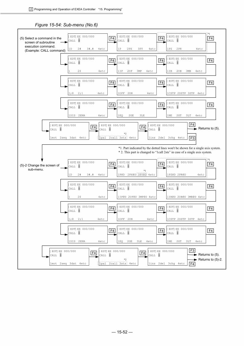
2 Programming and Operation of EXEA Controller “15. Programming”
— 15-52 —
Figure 15-54: Sub-menu (No.6)
F3F4F4
F4F4
F4F4
F4F4
F4F4
F4F4
*1
F4F4
F4F4
F4F4
F4F4
[EDT]EE 000/000CALL $
1P 2PX 3PY 4etc
(5) Select a command in thescreen of subroutineexecution command.(Example: CALL command)
F4
[EDT]EE 000/000CALL $
1CSTP 2DSTP 3STP 4etc
[EDT]EE 000/000CALL $
1OFF 2ON 4etc
[EDT]EE 000/000CALL $
1;8 2;1 4etc
[EDT]EE 000/000CALL $
1_ 2$ 4etc
[EDT]EE 000/000CALL $
1D 2# 3#.# 4etc
[EDT]EE 000/000CALL $
1IP 2OP 3MP 4etc
F4
F4
[EDT]EE 000/000CALL $
1PZ 2PR 4etc
[EDT]EE 000/000CALL $
1IB 2OB 3MB 4etc
(5)-2 Change the screen ofsub-menu.
Returns to (5).Returns to (5)-2.
F4
[EDT]EE 000/000CALL $
1NE 2GT 3LT 4etc
[EDT]EE 000/000CALL $
1EQ 2GE 3LE
[EDT]EE 000/000CALL $
1DIS 2ENA 4etc
F4
[EDT]EE 000/000CALL $
1pal 2call 3sts 4etc*2
Returns to (5).
*1. Part indicated by the dotted lines won't be shown for a single axis system.* 2. This part is changed to “1call 2sts” in case of a single axis system.
[EDT]EE 000/000CALL $
1mot 2seq 3dat 4etc F3
F4[EDT]EE 000/000CALL $
1ins 2del 3chg 4etc
*1
[EDT]EE 000/000CALL $
1P@D 2PX@D 3PY@D 4etc*1
F4
[EDT]EE 000/000CALL $
1CSTP 2DSTP 3STP 4etc
[EDT]EE 000/000CALL $
1OFF 2ON 4etc
[EDT]EE 000/000CALL $
1;8 2;1 4etc
[EDT]EE 000/000CALL $
1_ 2$ 4etc
[EDT]EE 000/000CALL $
1D 2# 3#.# 4etc
[EDT]EE 000/000CALL $
1IP@D 2OP@D 3MP@D 4etc
F4
F4
[EDT]EE 000/000CALL $
1PZ@D 2PR@D 4etc
[EDT]EE 000/000CALL $
1IB@D 2OB@D 3MB@D 4etc
[EDT]EE 000/000CALL $
1NE 2GT 3LT 4etc
[EDT]EE 000/000CALL $
1EQ 2GE 3LE 4etc
[EDT]EE 000/000CALL $
1DIS 2ENA 4etc
F4
[EDT]EE 000/000CALL $
1pal 2call 3sts 4etc*2
[EDT]EE 000/000CALL $
1mot 2seq 3dat 4etc
[EDT]EE 000/000CALL $
1ins 2del 3chg 4etc
*1

2 Programming and Operation of EXEA Controller “15. Programming”
— 15-53 —
Figure 15-55: Sub-menu (No.7)
(6) Select a command in thescreen of operationcondition control screen.(Example: TYP command)
F3
(6)-2 Change the screenof sub-menu.
Returns to (6).[EDT]EE 000/000TYP &
1ins 2del 3chg 4etc
F3
Returns to (6)-2.F4
F4
[EDT]EE 000/000TYP &
1= 4etc
[EDT]EE 000/000TYP &
1SPD 2ACC 3DAC 4etc
F4
[EDT]EE 000/000TYP &
1SR 2AR 3BR 4etc
F4
[EDT]EE 000/000TYP &
1S 2A 3B 4etc
Returns to (6).
F4
[EDT]EE 000/000TYP &
1PR 4etc
[EDT]EE 000/000TYP &
1PX 2PY 3PZ 4etc
F4
[EDT]EE 000/000TYP &
1U 2P 3& 4etc
[EDT]EE 000/000TYP &
1D 2# 3#.# 4etc
[EDT]EE 000/000TYP &
1SPDR 2ACCR 3DACR 4etc
F4F4 [EDT]EE 000/000TYP &
1Xp 2Yp 3Zp 4etc
*1. Part indicated by the dotted lines won't beshown for a single axis system.
* 2. This part is changed to “1call 2sts” in caseof a single axis system.
F4[EDT]EE 000/000TYP &
1Rp 4etc
F4
F4
F4F4
[EDT]EE 000/000TYP &
1ins 2del 3chg 4etc
F4
[EDT]EE 000/000TYP &
1PBS 2ESCZ 3ESCR 4etc
*1
*1
[EDT]EE 000/000TYP &
1UNT 2NOF 4etc
[EDT]EE 000/000TYP &
1STP 2CSTP 4etc
[EDT]EE 000/000TYP &
1EMST 2ALM 4etc
F4
F4F4
[EDT]EE 000/000TYP &
1UPR 2LWR 3POS 4etc
F4F4 [EDT]EE 000/000TYP &
1mot 2seq 3dat 4etc
F4[EDT]EE 000/000TYP &
1pal 2call 3sts 4etc*2
*1
*1
*1
F4
[EDT]EE 000/000TYP &
1= 4etc
[EDT]EE 000/000TYP &
1SPD 2ACC 3DAC 4etc
F4
[EDT]EE 000/000TYP &
1SR@D 2AR@D 3BR@D 4etc
F4
[EDT]EE 000/000TYP &
1S@D 2A@D 3B@D 4etc
F4
[EDT]EE 000/000TYP &
1PR@D 4etc
[EDT]EE 000/000TYP &
1PX@D 2PY@D 3PZ@D 4etc
F4
[EDT]EE 000/000TYP &
1U@D 2P@D 3& 4etc
[EDT]EE 000/000TYP &
1D 2# 3#.# 4etc
[EDT]EE 000/000TYP &
1SPDR 2ACCR 3DACR 4etc
F4F4 [EDT]EE 000/000TYP &
1Xp@D 2Yp@D 3Zp@D 4etc
F4[EDT]EE 000/000TYP &
1Rp@D 4etc
F4
F4
F4F4
[EDT]EE 000/000TYP &
1PBS 2ESCZ 3ESCR 4etc
*1
*1
[EDT]EE 000/000TYP &
1UNT 2NOF 4etc
[EDT]EE 000/000TYP &
1STP 2CSTP 4etc
[EDT]EE 000/000TYP &
1EMST 2ALM 4etc
F4
F4F4
[EDT]EE 000/000TYP &
1UPR 2LWR 3POS 4etc
F4F4 [EDT]EE 000/000TYP &
1mot 2seq 3dat 4etc
F4[EDT]EE 000/000TYP &
1pal 2call 3sts 4etc*2
*1
*1
*1
*1
*1

2 Programming and Operation of EXEA Controller “15. Programming”
— 15-54 —
15.2.6. Procedure for Editing Program Command
� Inputting and editing typical command are described below. Refer to “15.2.7. Description ofProgram Command” for other command.
� Input a command, then press SET key to advance to next step automatically. Proceed to inputcommands for programming.
� See “15.3. Examples of Program” for the examples of program.
Figure 15-56: Editing program command
Press F1 key.
PressMODE key.
PressMODE key.
PressMODE key.
: Program editing screen 1
Press F4 key.
: External control mode screen 1
: External control mode screen 2
Press F1 key.
: Menu selection screen 1
Press F4 key.
: Menu selection screen 2
Press F1 key.
: Programming screen 1
Press F1 key.
* No indication for a single axis system.
Set to programming mode referring to“8.2. Selection of Control Mode.”
Make and input operation program in this screen using the commands.
Select “2prog” and set a program number in this screen in advance.The number “000” is set in this example.(“15.2.3.2. Setting Procedure for Program Number.”)
: Program command editing screen[EDT]EE 000/000
1SRV 2HOM 4etc
[EDT]E 000/000
1EDT 2NAM 3MEM 4etc
[EDT] 000
1EDT 2prog 4etc
[MENU]
1EDT 2TCH 3PAL 4etc
[MENU]
1RUN 2ORG 3JOG 4etc
[External]
1TBX 4etc
[External]
1RUN 2IO 3FNC 4etc
Turn on power

2 Programming and Operation of EXEA Controller “15. Programming”
— 15-55 —
15.2.6.1. Editing Program Command: MOV
Exercise example: MOV P1234 S300 A5 B2 &AFW
MOV : Command for linear motion.P1234 : Move to the point on the coordinates 1234.S300 : Moving speed 300 mm/sA5 : Acceleration 5m/s2
B2 : Deceleration 2m/s2
&AFW : A --- Positioning in absolute coordinates.F --- FIN (complete positioning) output is on.W--- Normal process. (No multitask.)
Figure 15-57: Editing MOV command: No.1
Press F4 key.
: Input screen of point number.
: MOV command selection screen
: Program command editing screen 1
Press F4 key.
[EDT]EE 000/000
1SRV 2HOM 4etc
[EDT]EE 000/000MOV P0000
1U 2P 3& 4etc
� Select MOV command to get the screen. Pointnumber is indicated and the cursor is on theposition of P.
� When inputting other data, select from the menusbelow.
[EDT]EE 000/000
1MOV 2ARC 3CIR 4etc
[EDT]EE 000/000
1MSPD 2MSTP 3MEND 4etc
Press F1 key.
: Continues to the nextpage.
� Input by numeric keys ( 0 to 9 ). When CLRis pressed, it indicates 0000.
: Refer to Figure 15-50: Sub-menu (No.2) when settingUnit (optional). (for multi-axis combination only.)
: Returns to the programediting screen.
� Example screen after the power is turned on.mot (motion command) is initially selected.
Press F4 key.
[EDT]EE 000/000
1MSTS 4etc
Press F4 key.
Press F4 key.
Press F4 key.
Press F4 key.
[EDT]EE 000/000MOV P0000
key� Press once : Number can be input from
the place of thousand.� Press twice : Number can be inputted from
the place of hundred.� Press three times : Number can be inputted from
the place of ten.
Press 1 key.
Press F4 key.
Press 3 key.
Press 4 key.
[EDT]EE 000/000
1MOVM 2ARCC 3CIRC 4etc
[EDT]EE 000/000
1CPS 2CPE 4etc
[EDT]EE 000/000
1mot 2seq 3dat
[EDT]EE 000/000
1pal 2call 3sts 4etc
[EDT]EE 000/000MOV P1000
Press 2 key.
[EDT]EE 000/000MOV P1200
[EDT]EE 000/000MOV P1230
[EDT]EE 000/000MOV P1234_
Press key.Press SET key.Press MODE key.
: Returns to the programediting screen.
To continue to enter moreoptional commands:
To complete enteringcommands:
To cancel input ofcommand:
Press key.
Editing programcommand
*1
*1. Part indicated by the dotted lines won't be shown for a single axis system.*2. This part is changed to “1call 2sts” in case of a single axis system.
*1
*2
*1

2 Programming and Operation of EXEA Controller “15. Programming”
— 15-56 —
Figure 15-58:Editing MOV command: No.2
Press key.
Press F3 key.
� Example of setting speedSpeed is set to 300 mm/s.
: Screen to enter options
: MOV command editing screen(continued)
Press F4 key.
: Select speed setting in themenu.
� Select data. Options of MOVcommand are:
S : Set speedSR : Set speed. (%)A : Set acceleration.AR : Set acceleration. (%)B : Set deceleration.BR : Set deceleration. (%)& : Set motion format.
SR, AR, BR: It is based onLocus Speed and LocusAccel which are set to theinitial system setting inpercent (%).
Entering other options leadsto Syntax error. Itnecessitates to corrects input.
Press F4 key.
Press F4 key.
Press F4 key.
Press F4 key.
Press F1 key.
[EDT]EE 000/000MOV P1234 _
1U 2P 3& 4etc
[EDT]EE 000/000MOV P1234 _
1Xp 2Xs 3X 4etc
[EDT]EE 000/000MOV P1234 _
1Yp 2Ys 3Y 4etc
[EDT]EE 000/000MOV P1234 _
1Zp 2Zs 3Z 4etc
[EDT]EE 000/000MOV P1234 _
1Rp 2Rs 3R 4etc
[EDT]EE 000/000MOV P1234 _
1S 2A 3B 4etc
[EDT]EE 000/000MOV P1234 S1200.0
1S 2A 3B 4etc
� Select deceleration settingfrom the menu.
Note: Sign “<” denotes thatthere is data in front of it.
� Select acceleration settingfrom the menu.
Note: Sign “<” indicates thatthere is data in front of it.
[EDT]EE 000/000MOV P1234 S0300.0 _
1S 2A 3B 4etc
Press F2 key.
[EDT]EE 000/000MOV S0300.0 A35.0 <1S 2A 3B 4etc
[EDT]EE 000/000MOV S0300.0 A05.0_ <
� Example of acceleration setting Acceleration is set to 5m/s2.
[EDT]EE 000/000MOV A05.0 B35.0 <1S 2A 3B 4etc
[EDT]EE 000/000MOV S0300.0 A05.0 _
1S 2A 3B 4etc
[EDT]EE 000/000MOV A05.0 B02.0_ <
� Example of deceleration setting Deceleration is set to 2m/s2.
Continues to the next page.
[EDT]EE 000/000MOV A05.0 B02.0 _ <1S 2A 3B 4etc
� Select motion format.
[EDT]EE 000/000MOV P1234_
[EDT]EE 000/000MOV P1234 S0300.0_
Editing programcommand
Press to move the cursorto right. Way of inputtingnumeric numbers is the sameas inputting coordinates data.
* Part in the dotted lines is not indicated for a single axis system.
Press to move the cursorto right. Way of inputtingnumeric numbers is the sameas inputting coordinates data.
Press to move the cursorto right. Way of inputtingnumeric numbers is the sameas inputting coordinates data.
*
Press key.
Press key.
Press key.
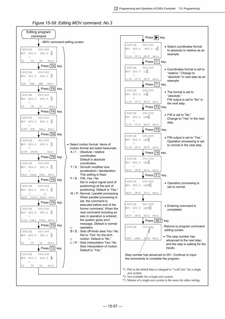
2 Programming and Operation of EXEA Controller “15. Programming”
— 15-57 —
Figure 15-59: Editing MOV command: No.3
: MOV command editing screen
Press F4 key.
Press F4 key.
Press F4 key.
Press F4 key.
Press F4 key.
Press F4 key.
[EDT]EE 000/000MOV A05.0 B02.0 _ <1SR 2AR 3BR 4etc
[EDT]EE 000/000MOV A05.0 B02.0 _ <1D 2# 3= 4etc
[EDT]EE 000/000MOV A05.0 B02.0 _ <1OFF 2ON 3ALL 4etc
[EDT]EE 000/000MOV A05.0 B02.0 _ <1CUR 2RSTA 4etc
[EDT]EE 000/000MOV A05.0 B02.0 _ <1mot 2seq 3dat 4etc
[EDT]EE 000/000MOV A05.0 B02.0 _ <1pal 2call 3sts 4etc
Press F4 key.
[EDT]EE 000/000MOV A05.0 B02.0 _ <1ins 2del 3chg 4etc
� Select coordinates formatto absolute or relative as anexample.
[EDT]EE 000/000MOV A05.0 B02.0 &_ <1I/A 2T/S 3N/F 4etc
Press F1 key.
[EDT]EE 000/000MOV B02.0 &I_ <1I/A 2T/S 3N/F 4etc
[EDT]EE 000/000MOV A05.0 B02.0 & <1U 2P 3& 4etc
[EDT]EE 000/000MOV B02.0 &AN_ <1I/A 2T/S 3N/F 4etc
[EDT]EE 000/000MOV B02.0 &AF_ <1W/P 2B/E 3H/L 4etc
Press F3 key.
[EDT]EE 000/000MOV B02.0 &AF_ <1I/A 2T/S 3N/F 4etc
Press F4 key.
� Operation processing isset to normal.
[EDT]EE 000/001
1MOV 2ARC 3CIR 4etc
[EDT]EE 000/000MOV A05.0 B02.0 _ <1S 2A 3B 4etc
� Select motion format. Items ofmotion format are listed hereunder.A / I : Absolute / relative
coordinates.Default is absolutecoordinates.
T / S : Smooth modified sineacceleration / decelerationThis setting is fixed.
F / N : FIN, Yes / NoSet to output signal (end ofpositioning) at the end ofpositioning. Default is “Yes.”
W / P : Normal / parallel processingWhen parallel processing isset, the command isexecuted before end of theformer command. When thenext command including anaxis in operation is entered ,the system gives errormessage. Default is normaloperation.
B / E : Sets off-limits area Yes / No.Set to “Yes” for the archmotion. Default is “No.”
L / H : Sets interpolation Yes / No.Sets interpolation of motion.Default is “Yes.”
Press F4 key.
[EDT]EE 000/000MOV A05.0 B02.0 _ <1U 2P 3& 4etc
Press F3 key.
� Coordinates format is set to“relative.” Change to“absolute” in next step as anexample.
Press F1 key.
[EDT]EE 000/000MOV B02.0 &A_ <1I/A 2T/S 3N/F 4etc
� The format is set to“absolute.”FIN output is set to “No” inthe next step.
Press F3 key.
� FIN is set to “No.”Change to “Yes” in the nextstep.
� FIN output is set to “Yes.”Operation processing is setto normal in the next step.
Press F1 key.
[EDT]EE 000/000MOV B02.0 &AFW_ <1W/P 2B/E 3H/L 4etc
[EDT]EE 000/000MOV B02.0 &AFW_ <1W/P 2B/E 3H/L 4etc
: Returns to program commandediting screen.
� Entering command iscompleted.
Press SET key.
� The step number hasadvanced to the next step,and the step is waiting for theinputs.
Step number has advanced to 001. Continue to inputthe commands to complete the program.
Press key.
Editing programcommand
*1. Part in the dotted lines is changed to “1call 2sts” for a singleaxis system.
*2. Not available for a single axis system.*3. Motion of a single axis system is the same for either setting.
*1
*3
*2

2 Programming and Operation of EXEA Controller “15. Programming”
— 15-58 —
15.2.6.2. Editing Program Command: ARC (for multi-axis combination only.)
Exercise example: ARC P1234 P1235
ARC : Circular arc interpolation command.P1234, P1235 : Execute circular arc interpolation passing the points of point register number
P1234 and P1235.In case of absolute coordinates, set two points for the interpolation as the currentposition becomes the starting point. For positioning in relative coordinates, it isrequired to set 3 points for the interpolation.
Figure 15-60: Editing ARC command
Press F2 key.
Press key.
Press F4 key.
: Selecting ARC command screen
: Program command editing screen 1
Press F4 key.
[EDT]EE 000/000
1SRV 2HOM 4etc
[EDT]EE 000/000ARC P0000 P0000
1U 2P 3& 4etc
� When ARC command is selected, two pointregister numbers are displayed, and the cursorwill be on the position of the first P. For enteringother command, select from the menus below.
[EDT]EE 000/000
1MOV 2ARC 3CIR 4etc
[EDT]EE 000/000
1MSPD 2MSTP 3MEND 4etc
For selecting Unit (optional), see“Figure 15-50: Sub-menu No.2.”
� The screen after the power is on. (example)‘mot’ (motion command) is initially set.
Press F4 key.
[EDT]EE 000/000
1MSTS 4etc
Press F4 key.
[EDT]EE 000/000
1MOVM 2ARCC 3CIRC 4etc
Press F4 key.
[EDT]EE 000/000
1CPS 2CPE 4etc
Press F4 key.
[EDT]EE 000/000
1mot 2seq 3dat 4etc
Press F4 key.
[EDT]EE 000/000
1pal 2call 3sts 4etc
The way to input point registernumber is the same as MOVcommand. Refer to “15.2.6.1.”
� Example: Setting point register numberFirst point number = 1234Second point number = 1235
� Setting third point numberIn case of positioning in absolute coordinatesformat, the third point can be omitted.
Current position = starting point First point number = middle point Second point number = end point
For positioning in relative coordinates format, it isrequired to set three points.
Press F4 key.
[EDT]EE 000/000ARC P1234 P1235_
[EDT]EE 000/000ARC P1234 P1235 _
1U 2P 3& 4etc
Press F2 key.
[EDT]EE 000/000MOV P1235 P0000 <1U 2P 3& 4etc
The way to input point number andoptions are the same as MOVcommand. Refer to “15.2.6.1.”
To cancel input data
Press MODE key.
: Returns to programediting screen.
To terminate enteringcommand
Press SET key.
: Returns to programcommand editing screen.
Editing programcommand

2 Programming and Operation of EXEA Controller “15. Programming”
— 15-59 —
15.2.6.3. Editing Program Command: TIM
Exercise example: TIM #0002.00
TIM : Command for timer.#0002.00 : Timer is set to 2 seconds.
Figure 15-61: Editing TIM command
Press F4 key.
: Program command editing screen 1
Press F4 key.
[EDT]EE 000/000
1SRV 2HOM 4etc
[EDT]EE 000/000
1MOV 2ARC 3CIR 4etc
[EDT]EE 000/000
1MSPD 2MSTP 3MEND 4etc
� The screen after the power is on. (example)‘mot’ (motion command) is initially set.Search for TIM command in ‘seq’ (sequence control command).
Press F4 key.
[EDT]EE 000/000
Press F4 key.
[EDT]EE 000/000
1MOVM 2ARCC 3CIRC 4etc
Press F4 key.[EDT]EE 000/000
1CPS 2CPE 4etc
Press F4 key.[EDT]EE 000/000
1mot 2seq 3dat 4etc
Press F4 key.
[EDT]EE 000/000
1pal 2call 3sts 4etc
Press F4 key.
To cancel input data
Press MODE key.
: Returns to programediting screen.
To terminate enteringcommand
Press SET key.
: Returns to programcommand editing screen.
Press F2 key.
[EDT]EE 000/000
1’ 2END 4etc
Press F4 key.
[EDT]EE 000/000
1TAG 2CMP 3JMP 4etc
Press F4 key.
[EDT]EE 000/000
1JEQ 2JGE 3JLE 4etc
Press F4 key.
[EDT]EE 000/000
1JNE 2JGT 3JLT 4etc
Press F4 key.
[EDT]EE 000/000
1TIM 2WAIT 4etc
Press F1 key.
[EDT]EE 000/000TIM #0000.00
1 4etc
: TIM command selecting screenParameters of TIM comprise #(numbers) and D (data register).
: Example of TIM inputTimer is set to 2 seconds.
Press key.
Editing programcommand
The way to input numerical data isthe same as point number of MOVcommand. Refer to “15.2.6.1.”
[EDT]EE 000/000TIM #0000.00
[EDT]EE 000/000TIM #0002.00.
*1. Part indicated in the dotted lines won’t beshown for a single axis system.
*2. This part will be changed to “1call 2sts”for a single axis system.
*1
*2
*1
*1

2 Programming and Operation of EXEA Controller “15. Programming”
— 15-60 —
15.2.6.4. Editing Program Command: OUT
Exercise example: OUT OP00 ; 10000010OUT : Command to set output port.OP10 : Set output port to OP10 (OB100 ~ OB107) of general IO port.; 10000010 : Close output bit 1 (OB101) and bit 7 (OB107).
Figure 15-62: Editing OUT command
Press key.
Press F4 key.
: Program command editing screen 1
Press F4 key.
� The screen after the power is on. (example)‘mot’ (motion command) is initially set.Search for OUT command in ‘dat’ (data control command).
Press F4 key.
Press F4 key.
Press F4 key.
Press F4 key.
Press F4 key.
The way to input point number is thesame as the point number of MOVcommand. Refer to “15.2.6.1.”
Press F4 key.
Press F3 key.
Press F4 key.
Press F1 key.
� Decide the setting position by keys, and inputusing numeric key ( 0 , 1 ) or keys. .
� In the screen on left, the polarity is set to A contact(shipping set).
0 : Opens output port. (in case of B contact: close)1 : Closes output port. (in case of B contact : open)X : Repeats the output data of previous command.R : Reverses the data setting. (0 � 1 and 1 � 0)
� Example of setting: Bit 7 and 1 of output port are set toclose.
� Set output port and output data.Sign “>” indicates more data are on the right side.
: OUT command input screen
: Screen to input 8 bits data
: Set port number.
[EDT]EE 000/000OUT = ;10000010. <1;8 2;1 4etc
[EDT]EE 000/000OUT = ;00000000 <1;8 2;1 4etc
[EDT]EE 000/000OUT OP10 = ;0000000
>
[EDT]EE 000/000OUT OP00 = ;0000000
>1D 2# 3#.# 4etc
[EDT]EE 000/000OUT OP00 = ;0000000
>1D 2# 3#.# 4etc
[EDT]EE 000/000
1OUT 2INP 3LCAL 4etc
[EDT]EE 000/000
1LD 2CAL 3TCH 4etc
[EDT]EE 000/000
1pal 2call 3sts 4etc
[EDT]EE 000/000
1mot 2seq 3dat 4etc
[EDT]EE 000/000
1CPS 2CPE 4etc
[EDT]EE 000/000
1MOVM 2ARCC 3CIRC 4etc
[EDT]EE 000/000
1MSTS 4etc
[EDT]EE 000/000
1SRV 2HOM 4etc
[EDT]EE 000/000
1MOV 2ARC 3CIR 4etc
[EDT]EE 000/000
1MSPD 2MSTP 3MEND 4etc
Press key.
Editing programcommand
Press key to move cursor.
To terminate enteringcommand
Press SET key.
: Returns to programcommand editing screen.
To cancel input data
Press MODE key.
: Returns to programediting screen.
*1. Part indicated in the dotted lines won’t beshown for a single axis system.
*2. This part will be changed to “1call 2sts”for a single axis system.
*1
*2
*1
*1
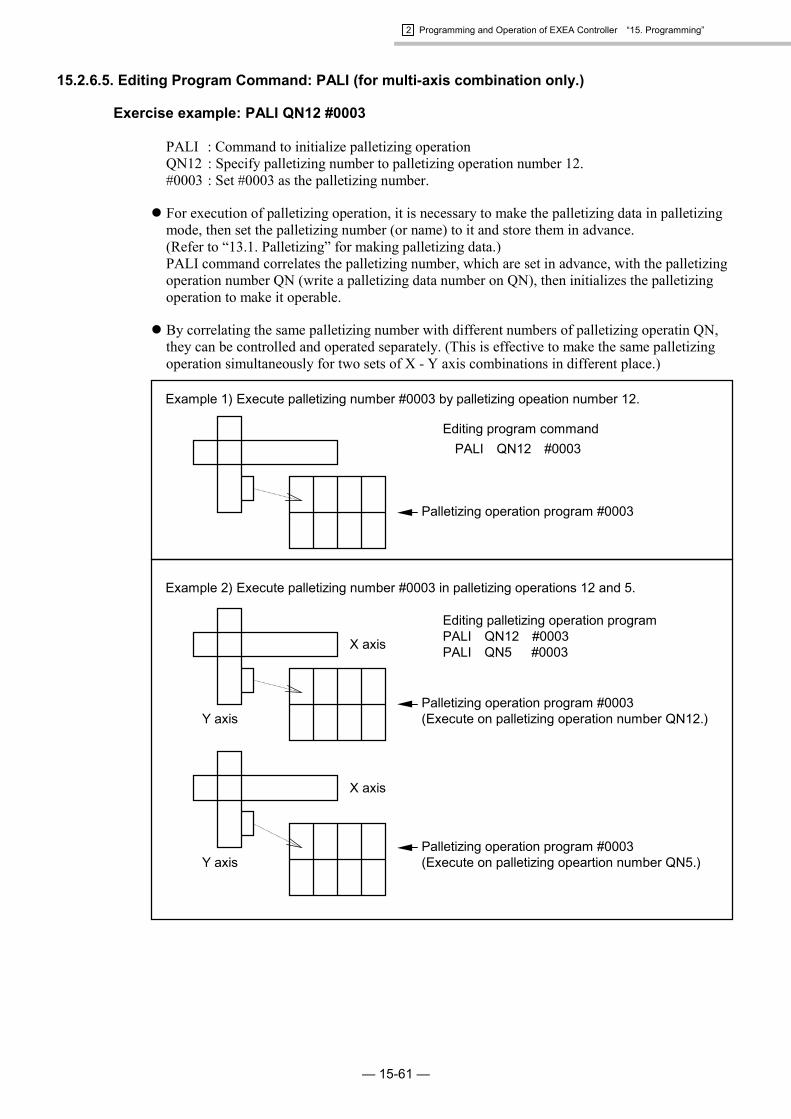
2 Programming and Operation of EXEA Controller “15. Programming”
— 15-61 —
15.2.6.5. Editing Program Command: PALI (for multi-axis combination only.)
Exercise example: PALI QN12 #0003
PALI : Command to initialize palletizing operationQN12 : Specify palletizing number to palletizing operation number 12.#0003 : Set #0003 as the palletizing number.
� For execution of palletizing operation, it is necessary to make the palletizing data in palletizingmode, then set the palletizing number (or name) to it and store them in advance.(Refer to “13.1. Palletizing” for making palletizing data.)PALI command correlates the palletizing number, which are set in advance, with the palletizingoperation number QN (write a palletizing data number on QN), then initializes the palletizingoperation to make it operable.
� By correlating the same palletizing number with different numbers of palletizing operatin QN,they can be controlled and operated separately. (This is effective to make the same palletizingoperation simultaneously for two sets of X - Y axis combinations in different place.)
X axis
Y axis
Example 2) Execute palletizing number #0003 in palletizing operations 12 and 5.
Example 1) Execute palletizing number #0003 by palletizing opeation number 12.
X axis
Y axis
Palletizing operation program #0003(Execute on palletizing operation number QN12.)
Palletizing operation program #0003(Execute on palletizing opeartion number QN5.)
Editing program commandPALI QN12 #0003
Editing palletizing operation programPALI QN12 #0003PALI QN5 #0003
Palletizing operation program #0003

2 Programming and Operation of EXEA Controller “15. Programming”
— 15-62 —
Figure 15-63: Editing PALI command
Press F4 key.
:Input screen of PALI command
: Program command editing screen 1
Press F4 key.
[EDT]EE 000/000
1SRV 2HOM 4etc
[EDT]EE 000/000
1MOV 2ARC 3CIR 4etc
[EDT]EE 000/000
1MSPD 2MSTP 3MEND 4etc
� This screen appears after the power is on. (example)‘mot’ (motion command) is initially set. Search for PALIcommand in ‘pal’ (palletizing motion command).
Press F4 key.
[EDT]EE 000/000
1MSTS 4etc
Press F4 key.
[EDT]EE 000/000
1MOVM 2ARCC 3CIRC 4etc
Press F4 key.
[EDT]EE 000/000
1CPS 2CPE 4etc
Press F4 key.
[EDT]EE 000/000
1mot 2seq 3dat 4etc
Press F4 key.
[EDT]EE 000/000
1pal 2call 3sts
Press F4 key.
Press F1 key.
[EDT]EE 000/000
1PALI 2PALL 3PALE 4etc
Press F1 key.
[EDT]EE 000/000PALI QN00 #0000
1QN 2QP 4etc
[EDT]EE 000/000PALI QN00 #0000
[EDT]EE 000/000PALI QN12 #0000
[EDT]EE 000/000PALI QN12 #0003_
� Input example (#0003)The number3 edited in the editing screen ofpalletizing is correlated with the palletizing operationnumber 12 in the program and is initialized.
� How to input the palletizing number.Use keys to move to set position andinput number using numeric keys. ( 0 to 9 )
(Input setting range is 0 to 15.)
� Set the number of palletizing operation to be used inthe program. (In the left screen, it is part of QN00.)Setting range is QN00 to QN15.
� The command initializes palletizing operation.It correlates the palletizing number, that is edited andset in "16.1. Palletizing," with the palletizing operationnumber to be used in the program. (In the left screen,the palletizing number is part of #0000.)
� Use keys to move to setting position and inputthe number using numeric number keys. ( 0 to 9 )
Press CLR to clear input data.
(Input example is QN12.)
[EDT]EE 000/000PALI QN12_ #0000
Press key.
Editing programcommand
Press key to move cursor.
To terminate enteringcommand
Press SET key.
: Returns to programcommand editing screen.
To cancel input data
Press MODE key.
: Returns to programediting screen.

2 Programming and Operation of EXEA Controller “15. Programming”
— 15-63 —
15.2.6.6. Editing Program Command: CALL
Exercise example: CALL $ABCD
CALL : Command to call subroutine.$ABCD : Call the program named $ABCD.
Figure 15-64: Editing CALL command
[EDT]EE 000/000
1MOVM 2ARCC 3CIRC 4etc
Press F4 key.
: Input screen of CALL command
: Program command editing screen 1
Press F4 key.
[EDT]EE 000/000
1SRV 2HOM 4etc
[EDT]EE 000/000
1MOV 2ARC 3CIR 4etc
[EDT]EE 000/000
1MSPD 2MSTP 3MEND 4etc
� This screen appears after the power is turned on. (example) ‘mot’ (motion command) is initially set.Search for CALL command in ‘call’ (subroutine execution command).
Press F4 key.
[EDT]EE 000/000
1MSTS 4etc
Press F4 key.
Press F4 key.[EDT]EE 000/000
1CPS 2CPE 4etc
Press F4 key.[EDT]EE 000/000
1mot 2seq 3dat 4etc
Press F4 key.
Press F4 key.
Press F2 key.
[EDT]EE 000/000
1CALL 2RET 3RSTA 4etc
Press F1 key.
[EDT]EE 000/000CALL $
1D 2# 3#.# 4etc
Press key.
[EDT]EE 000/000CALL $_
� Call command of subroutine.Call the subroutine in this program or other one.
� The left screen shows an example to callsubroutine of other program.
� Use keys ( A to Z or 0 to 9 ) and
numeric number keys to input a name ofsubroutine.
� Example of inputting name of subroutine(Name of program: ABCD)
[EDT]EE 000/000CALL $ABCD_
[EDT]EE 000/000
1pal 2call 3sts 4etc
Editing programcommand
To terminate enteringcommand
Press SET key.
: Returns to programcommand editing screen.
To cancel input data
Press MODE key.
: Returns to programediting screen.
*1
*2
*1
*1
*1. Part indicated in the dotted lines won’t beshown for a single axis system.
*2. This part will be changed to “1call 2sts”for a single axis system.

2 Programming and Operation of EXEA Controller “15. Programming”
— 15-64 —
15.2.6.7. Editing Program Command: UNT (for multi-axis combination only.)
(Refer to “9.5. Parameter for Unit Setting.”)
Exercise example: UNT U1
UNT : Command to set unit.U1 : Specify unit number 1.
Figure 15-65: Editing UNIT command
Press F4 key.
: Input screen of UNIT command
: Program command editing screen 1
Press F4 key.
� This screen appears after the power is turned on. (example)‘mot’ (motion command ) is initially set.Search UNT in ‘sts’ (operating condition control command).
Press F4 key.
Press F4 key.
Press F4 key.
Press F4 key.
Press F4 key.
Press F4 key.
Press F3 key.
Press F1 key.
Press key.
� Specify the unit number being used in the program.Refer to “9.5. Parameter for Unit Setting.”(Initial setting is UNIT 1.)
� Unit number input example (U3)
[EDT]EE 000/000
1pal 2call 3sts 4etc
[EDT]EE 000/000
1mot 2seq 3dat 4etc
[EDT]EE 000/000UNT U3_
[EDT]EE 000/000
1CPS 2CPE 4etc
[EDT]EE 000/000
1MOVM 2ARCC 3CIRC 4etc
[EDT]EE 000/000
1MSTS 4etc
[EDT]EE 000/000UNT U1
[EDT]EE 000/000UNT U1
1D 2# 3#.# 4etc
[EDT]EE 000/000
1UNT 2SPD 3TYP 4etc
[EDT]EE 000/000
1MSPD 2MSTP 3MEND 4etc
[EDT]EE 000/000
1MOV 2ARC 3CIR 4etc
[EDT]EE 000/000
1SRV 2HOM 4etc
Editing programcommand
To terminate enteringcommand
Press SET key.
: Returns to programcommand editing screen.
To cancel input data
Press MODE key.
: Returns to programediting screen.
� Use numeric number keys ( 1 to 8 ) to input unit
number.

2 Programming and Operation of EXEA Controller “15. Programming”
— 15-65 —
15.2.6.8. Editing Program Command: END
Exercise example: END CSTP
END CSTP: Complete the programmed operation.
Figure 15-66: Editing END command
[EDT]EE 000/000
1pal 2call 3sts 4etc
[EDT]EE 000/000
1CPS 2CPE 4etc
Press F4 key.
[EDT]EE 000/000
1MOVM 2ARCC 3CIRC 4etc
[EDT]EE 000/000
1MOV 2ARC 3CIR 4etc
To terminate enteringcommand
Press SET key.
: Returns to programcommand editing screen.
To cancel input data
Press MODE key.
: Returns to programediting screen.
*1
*2
*1
*1
Press F4 key.
: Program command editing screen 1
Press F4 key.
[EDT]EE 000/000
1SRV 2HOM 4etc
[EDT]EE 000/000
1MSPD 2MSTP 3MEND 4etc
� This screen appears after the power is turned on.‘mot’ (motion command) is initially set.Search END command in ‘seq’ (sequence control command).
Press F4 key.
[EDT]EE 000/000
1MSTS 4etc
Press F4 key.
Press F4 key.[EDT]EE 000/000
1mot 2seq 3dat 4etc
Press F4 key.
Press F4 key.
Press F2 key.
[EDT]EE 000/000
1’ 2END 4etc
Press F2 key.
[EDT]EE 000/000END CSTP
1_ 4etc
*1. Part indicated in the dotted lines won’t beshown for a single axis system.
*2. This part will be changed to “1call 2sts”for a single axis system.
Editing programcommand

2 Programming and Operation of EXEA Controller “15. Programming”
— 15-66 —
15.2.6.9. Editing Program Command: Recovery from Syntax Error
� Input of command will be disabled when a syntax error occurs due to incorrect instruction. Thefollowing procedures show the way of how to recover from the syntax error. Be sure to input thecorrect instructions.
Figure 15-67: Procedure for recovery from Syntax error
Press F1 key.
[EDT]EE 000/000
1pal 2call 3sts 4etc
[EDT]EE 000/000
1MOVM 2ARCC 3CIRC 4etc
[EDT]EE 000/000
1MOV 2ARC 3CIR 4etc
*1
*2
*1
*1
Press F4 key.
: Program command editing screen 1
Press F4 key.
[EDT]EE 000/000
1SRV 2HOM 4etc
[EDT]EE 000/000MOV P0000
1U 2P 3& 4etc
� Syntax errorEach command has its own syntax and the inputs shall follow the its syntax.If not, Syntax error alarm arises and you cannot input any command.(Refer to “15.2.7. Description of Program Command” for the syntax.)Review the contents of input and enter correct ones.
[EDT]EE 000/000
1MSPD 2MSTP 3MEND 4etc
� This screen appears after the power is on. (example)‘mot’ (motion command) is initially set.In this procedure, MOV command is selected as an example.
Press F4 key.
[EDT]EE 000/000
1MSTS 4etc
Press F4 key.
Press F4 key.[EDT]EE 000/000
1CPS 2CPE 4etc
Press F4 key.[EDT]EE 000/000
1mot 2seq 3dat 4etc
Press F4 key.
[EDT]EE 000/000MOV P1234 U1.
: Select screen of MOV command
Press SET key.
[EDT]EE 000/000MOV P1234 U1
Syntax error
Press F4 key.
Press MODE key.
[EDT]EE 000/000MOV P1234 U1
1MOV 2ARC 3CIR 4etc
Press MODE key.
� Input example of MOV commandCommand to move to the position data P1234 is instructed toUnit 1 module main unit.
• • •When enter key ( SET key) is pressed,
• • •Syntax error message appears and the system does notaccept the inputs by keys.
� Recovery procedure
Return to the program command editing screen by MODE key.
Then review the command ------You can see that order of U1 and P1234 points is reversed.There are two ways for recovery from this state.
(i) Cancel input using MODE key.
(ii) Use keys to move to the position, and edit again fordeleting or inserting command data.
: Procedure for recoveryUse keys to move position of U1 and delete it.(Refer to “Figure 15-50: Sub-menu 2” for the way ofdeletion.)
Editing (deletion)
[EDT]EE 000/000MOV P1234
1ins 2del 3chg 4etc
� (U1 is deleted.)
� (U1 is deleted.)
Editing (insertion)
: Procedure for recovery 2Use keys to move position of P1234 and insertU1 to the position.(Refer to “Figure 15-50: Sub-menu 2” for the way ofinsertion.)
[EDT]EE 000/000MOV U1 P1234
1U 2P 3& 4etc
Procedure for recovery is completed.Press SET key and input next command.
To cancel inputcommand
: Returns to the programediting screen.Go to the program commandediting screen again.
To continue optionalinput.
[EDT]EE 000/000MOV P1234 U1
1U 2P 3& 4etc
[EDT]EE 000/000MOV P1234 _
1ins 2del 3chg 4etc
Procedure forrecovery
*1
Editing programcommand
*1. Part indicated in the dotted lines won’t beshown for a single axis system.
*2. This part will be changed to “1call 2sts”for a single axis system.

2 Programming and Operation of EXEA Controller “15. Programming”
— 15-67 —
15.2.7. Description of Program Command
15.2.7.1. Usable Data for Program
1 D×××--- Data register
� 200 data registers, from register number D000 to D199, are available. Effective data range ofcontents in data register is between - 9999.99 to +9999.99.
* Data register number D200 to D999 are reserved.
2 P×××× --- Point register (Coordinate data)
� Point registers between P000 and P3999 are available. Number of coordinate data in accordancewith controllable axes of EXEA controller may be set to a point register. For a single axiscontroller, only one coordinate data of X axis can be registered, while for a multi-axis controller,four coordinate data of X to R axes can be registered. Effective range of data is -9999.99 to9999.99.
* Point register numbers P4000 to P9999 are reserved.
� Normally a point register number is specified by numeric numbers. However, it is possible tospecify a point register using a data register indirectly. An example of expression is shownbelow.
Example: P@D000 --- Contents of D000 indicates the point register number.
� For specifying an axis in point register, put the name of axis (X, Y, Z and R) following letter P.Examples of indication are shown below.
Example: PX0000 (Specify number directly.), PX@D000 (Specify number indirectly.)
3 X×××, Y×××, Z×××, R××× --- Coordinate data, ‘axis switch’ and specifying axis
� When specifying the coordinate data, write numeric numbers next to the name of an axis asshown below to set ‘axis switch’ and ‘axis indication’.
Example: (for multi-axis combination, only X axis can be set for a single axis system.)
(1) Coordinate data (select Xp~Rp)X0001.00 Y0003.00--- Specify coordinate data 1.00 to X axis and 3.00 to Y
axis.
(2) Switching axis (select Xs~Rs)X1 Y0 -------------------- Set “axis switch” for command such as TCH.
(3) Specify axis (select X~R)X Y ----------------------- Specify axes for commands such as MSTP and MEND.
� Coordinate data is specified normally by numeric numbers. However, it may be specified by dataregister indirectly. Example of specifying coordinate data using a data register is shown below.
Example: X@D000---Contents of D000 indicates status of coordinates or value of Xcoordinate.

2 Programming and Operation of EXEA Controller “15. Programming”
— 15-68 —
4 S×××, A×××, B××× --- Specifying data of motion speed and acceleration /deceleration
� Speed and acceleration / deceleration data used in the motion command (MOV etc.) are specifiedas shown below.
Example:S1200------ 1200 (mm/s) is specified to motion speed.A10.3------ 10.3 (m/s2) is specified to motion acceleration.B10.3 ------ 10.3 (m/s2) is specified to motion deceleration.
� When the data is set to a motion command, it is only effective in the specific motion commandin the same step.
� Speed and acceleration / deceleration data are specified normally by numeric numbers. However,it may be specified by data register indirectly. Examples of indicating data are shown below.
Example:S@D000 ---- Contents of D000 indicate motion speed.A@D001 --- Contents of D000 indicate motion acceleration.B@D001---- Contents of D000 indicate motion acceleration.
5 SR×××, AR×××, BR××× --- Specifying data of motion speed and acceleration /deceleration in percent
� Motion speed and acceleration / deceleration may be specified by the percentage (%) of thespecified speed (resultant speed) and acceleration / deceleration, which are initially set as theparameters. Setting range is 1 to 200.
Example:SR30.5 ------ Motion speed is set to 30.5 % of the specified motion speedAR80.5------ Motion acceleration is set to 80.5 % of the specified motion acceleration.BR80.5 ------ Motion deceleration is set to 80.5 % of the specified motion deceleration.
� Normally speed and acceleration/deceleration are specified by the numeric values. However, it ispossible to specify those factors indirectly using the data registers. Examples are shown below.
Example:SR@D000-- Contents of D000 indicate ratio to the specified motion speed in %.AR@D001 - Contents of D001 indicate ratio to the specified motion acceleration in %.BR@D001-- Contents of D001 indicate ratio to the specified motion deceleration in %.
6 Ux --- Unit number
� When the robot system has more than one unit, it is necessary to specify a unit number in theprogram to the units which are objectives of motion command. Setting range of unit numbers isbetween U1 and U8. Example of indication is shown below.
Example:U1-------- Specify Unit1 for the subject of motion command.
� Unit number is set normally by numeric keys. However, it may be set by the data resisterindirectly. Example is shown below.
Example:U@D000 --- Contents of data register D000 specify unit number.
� Only unit number 1 (U1) can be set to a single axis system.

2 Programming and Operation of EXEA Controller “15. Programming”
— 15-69 —
7 IP×××, Op×××, IB×××OB 02 and Ob××× --- Input / Output port
� It is possible to use Input / Output port number 00 to 01 and 10 to 13. Port number is controlledby 8 bit and set as shown below.
Example:00-------Control port 001-------Control port 110-------General port 011-------General port 112-------General port 213-------Control port 3
* Port number 02 to 07 and 14 to 77 are reserved.
� Input / Output port is described as shown below when the port is used as one unit.
Example:IP10------ Input, general port 0OB13 ---- Output, control port 1
� Describe the I/O port as shown below when only one bit in the port is used. Port number is 3digits. Two digits number in left indicate port number and one digit in right indicates bit number.
Example:IB101---- General Input port 0 : bit 1.OP01 ---- Output control port 1: bit 3
� Way of using Input / Output port is limited by the type of the port. The user may use the generalI / O port at its discretion, while the control I / O port is only available for reading out the status.
Control Input port ---------Only possible to read out the status of Input.General Input port---------Only possible to read out the status of Input.General Output port ------Both reading out and handling are possible.Control Output port -------It is possible to reading out the status of Output, while it is not
possible to handle the Output port.
� The port number can be set by numeric keys normally. However, it can be set by Data registerindirectly. Indication of the setting are shown below.
Example:OP@D000-------Contents of point register D000 indicate the Output port number.OB@D000 ------Contents of point register D000 indicate the Output port number or bit
number.

2 Programming and Operation of EXEA Controller “15. Programming”
— 15-70 —
8 Pattern of Input / Output
� When setting Output port by OUT command or reading out the status of Input port by CMPcommand, the task can be done either 8 bit data or 1 bit data. In such a case, Input / Outputpattern bit can be specified one by one. Each bit is specified by codes shown below.“;” (semicolon) is on the head of the character string of pattern.
0 ・・・ Output: Off --------------Input: Off1 ・・・ Output: On---------------Input: OnX ・・・ Output: No change -----Input: IgnoreR ・・・ Output: Reverse---------Input: – –
Example:;0101XR00------8 bit pattern;0 ------------------1 bit pattern
9 Character string for naming
� It is possible to specify name of tags and programs by a string of 1 to 8 characters. Capital lettersof alphabet and numeric numbers are only usable for naming. For a name of tag, “_ ”(under bar)shall be the head of character string while “$” shall be the head of character string for name of aprogram. ( “_ ” and “$” are not counted as a character.)
Example:_ABCDEFG ------Name of a tag “ABCDEFG”$ABCDEFG ------Program “ABCDEFG”
10 Character string for memo
� String of approximately 40 characters can be inserted as the comment to a program. Capital andsmall letters of alphabet, numeric numbers and the space are usable. An exclusive line forcomment shall be set. Character string of comment follows the space after “ ‘ ”.
Example:‘ ABC DEF GHI -------Comment: “ABC DEF GHI”
11 Numeric data
� When handling numeric data in programming, “#” shall be put on the head of numeric data.Numeric data may be an integer or a decimal fraction.
Example:#1--------- Numeric number.# 100.2 -- Coordinates, indication of percentage, acceleration/deceleration and speed,
etc.

2 Programming and Operation of EXEA Controller “15. Programming”
— 15-71 —
12 &××× --- Motion format of unit
� When operating a unit by motion command (such as MOV), it is possible to specify the motionformat. Motion format data begins with & and the codes of motion format follow it. The motionformat is listed below. The paired items cannot be set simultaneously.
� There are formats that cannot be specified depending on command.(Refer to “15.2.7.3. Program Command.”)
� In addition to it, the rules listed below shall be applied to specify the motion format.
(1) At least, one motion code shall be specified.
(2) Do not repeat motion code.
(3) The motion format shall be appeared in the following order.(A / I � T / S � F / N � W / P � B / E* � L / H)
A / I ---- Absolute coordinates / Relative coordinatesT / S---- Reserved: Either setting is for smooth modified sine acceleration /
deceleration.F / N --- Set FIN / No FIN (FIN: Output for end of positioning)W / P--- Normal processing command / Parallel processing command
*B / E --- Sets turnout. B: No E: Yes (Sets arch motion.)L / H --- Sets linear interpolation: L: Yes H: No
[Effective only for linear interpolation (MOV and MOVM). If linearinterpolation is not set, each axis will move independently under Locusspeed and Locus accel. For this time, motion of each axis is set to itsmaximum speed and acceleration/deceleration.]
* Not available for a single axis system.
� For instance, motion formats are initially set as follows.&ASFWBL (&ASFWL for a single axis system.)
� Example shown below are for improper order setting.&SAFL (incorrect) � &ASFL (correct)
13 QN××, QP×××× --- Control palletizing data (for multi-axis combination only.)
� In palletizing operation command, the control data different from the point register (P××××) isused for positioning. Setting ranges of two control data are shown below.Palletizing operation number (QN): QN00 to QN15 (total 16 operation numbers)Palletizing position number (QP) : QP0000 to QP9999 (total 1000 palletizing position numbers)
* QN 16 to QN99 are reserved.
The maximum number of palletizing position number QP×××× varies according to the settingformat of a pallet.
� Palletizing operation and palletizing position number are normally specified in numeric numbers.However, it is possible to specify them by data register indirectly. The followings show theexamples.
Example:QN@D000 ------Contents of D000 show the palletizing motion number.QP@D000-------Contents of D000 show the pallet number.

2 Programming and Operation of EXEA Controller “15. Programming”
— 15-72 —
14 MP××, MB××× (Imaginary Input / Output port)
� This is to hold Input / Output pattern of actual input and output (IP, OP) and to judge status of aport.
� Port numbers 0 to 1 are able to use for imaginary I/O port. The imaginary I/O port is kept in thememory same as the data register. It does not affect the outside conditions of EXEA controller.
* Port number 2 to 7 are reserved.
� It can substitute the actual port (IP, OP) in a program which uses I/O port.
� When it is used as a unit of port, describe the I/O port as shown below.
Example:MP1---------------Imaginary I/O port 1
� When use one bit only in the port, describe as shown below. The port number is two digit. Theleft side indicates the port number and the right indicates the bit number.
Example:MB11-------------Bit 1 of imaginary I/O port 1
� Normally the port number is indicated by numeric numbers, however, it is indicated indirectlyusing data registers. Following shows the examples.
Example:MP@D000 ------Contents of D000 indicate the number of I/O port.MB@D000------Contents of D000 indicates the numbers of port and bit.

2 Programming and Operation of EXEA Controller “15. Programming”
— 15-73 —
15.2.7.2. Symbol List to Describe Syntax of Program Command
� The symbols listed hereunder are used to describe the syntax of program command.(“15.2.7.3. Program Command.”)
UNT
#Numeric
D
P
PX
P@D
PX@D
X
X@D
S
S@D
SR
SR@D
A
A@D
AR
AR@D
B@D
BR
B
IP
BR@D
Numeric number(direct setting)
Point register : Specified axis unitdata (direct setting)
Point register : Specified axis unitdata (indirect setting)
Coordinate data / switch axis /specify axis (direct setting)
Coordinate data / switch axis /specify axis (indirect setting)
Command
Data register
Point register(direct setting)
Point register(indirect setting)
Motion speed (direct setting)
Motion speed (indirect setting)
Motion speed : Percentage(direct setting)
Motion speed: Percentage(indirect setting)
Motion acceleration(direct setting)
Motion acceleration(indirect setting)
Motion acceleration : Percentage(direct setting)
Motion acceleration : Percentage(indirect setting)
Motion deceleration(direct setting)
Motion deceleration(indirect setting)
Motion deceleration : Percentage(direct setting)
Input port (direct setting)
Motion deceleration : Percentage(indirect setting)
*1
*1
*1
*1
•••
•••
•••
•••
•••
•••
•••
•••
•••
•••
•••
•••
•••
•••
•••
•••
•••
•••
•••
•••
•••
•••
*2
*2
*2
*2
OP Output port (direct setting)•••
MP Imaginary Input/Output port(direct setting)•••
***
***
QP
QP@D
PAL name
IP@D
OP@D
IB
OB
IB@D
OB@D
U
QN
U@D
QN@D
Pattern
T characterstring
C characterstring
P characterstring
& motionformat
MB
MB@D
Keyword
Omission possible
Palletizing position number(direct setting)
Palletizing position number(indirect setting)
Character string of pallet name
Input port (indirect setting)
Output port (indirect setting)
Input port / every bit(direct setting)
Output port / every bit(indirect setting)
Input port / every bit(indirect setting)
Output port / every bit(indirect setting)
Motion unit (direct setting)
Palletizing operation number(direct setting)
Motion unit (indirect setting)
Palletizing operation number(indirect setting)
Input / Output pattern
Character string of Tag name(less than 8 characters)
Character string of comment(less than 40 characters)
Character string of programname (less than 8 characters)
Motion format of unit
Imaginary Input/Output • every bit(direct setting)
Imaginary Input/Output • every bit(indirect setting)
*1. X axis only for a single axis system. Indicate either one of X, Y, Z and R axis for a multi-axis combination.*2. Do not use in case of a single axis system.
•••
•••
•••
•••
•••
•••
•••
•••
•••
•••
•••
•••
•••
•••
•••
•••
•••
•••
•••
•••
•••
•••
*2

2 Programming and Operation of EXEA Controller “15. Programming”
— 15-74 —
15.2.7.3. Program Command
� The program commands are described hereunder in alphabetical order.
� Syntax, description of function and examples are shown in the manner as indicated below.
ESCZ Setting off-limits boundary of Z axis [Multi-axis controller]
wESCZ PX
PX@D
D
U
U@D
PX
PX@D
D
PX
PX@D
D
# Numeric # Numeric # Numeric
Command
Specify unit(omissionpossible)
Set data(Possible to specify same axis in triplicate.)*
� This is to specify off-limits boundary and turnout position for evading motion of Z axis inmotion command MOV. (Evading motion is an arch motion.)
� Three kinds of data, from left to right, the lower off-limits boundary, the upper off-limitsboundary and turnout position must be set.
� If the off-limits boundary data and turnout position are not specified in the initial setting, thiscommand is not valid. If it is necessary to change the off-limits boundary and turnout positionwhile programming, the initial setting shall be changed as described below.
Off-limits boundary: Data must be the effective numeric numbers.Turnout position : Set data other than OFF.
Refer to “9.3.4. Parameter for Position and Coordinates” for details.
Example 1: “ESCZ U1 #0000.00 #0100.00 #0120.00”
� Specify the off-limits boundary for Z axis of Unit 1. Set the lower off-limits boundaryto 0000.00 mm and the upper off-limits boundary to 100.00 mm. Turnout position is120 mm.
Example 2: “ESCZ U@D001 #1.23 PX0001 PX0002”
� When D001 is 1, X axis coordinate of P0001 is 200 mm and X axis coordinate ofP0002 is 250 mm, evading of Z axis of Unit 1 is set as below.
Lower off-limits boundary : 1.23 mmUpper off-limits boundary : 200.00 mmTurnout position : 250 mm
Program command
(1) SyntaxDescribes how to make program command.Solid lines in the syntax indicate necessary items while dotted lines indicate theitems that shall be added in case of need.
(2) DescriptionThis part describes fundamental function and the points to note.
(3) Examples of program commandProgram commands that can be practically used and description of them.
Rough description of function
(3)
(2)
(1)
Indicates type of controller whichemploys the function. [Multi-axis controller]
: 2 to 4 axes controller only. No indication
: Common to single axis andmulti-axis controller

2 Programming and Operation of EXEA Controller “15. Programming”
— 15-75 —
ARC Circular arc motion [Multi-axis controller]
Specify motion format(omission possible)
& motionformatS
S@D
SR
SR@D
A
A@D
AR
AR@D
B
B@D
BR
BR@D
ARC PU
U@D P@D
P
P@D
P
P@D
Specify unit. Start point(omission possible)
Passing point End point
Data setting (Speed, acceleration and deceleration)(omission possible)
Command
� This is circular arc motion command for a specified unit.
� This command is to execute circular arc interpolation defined by the point registers of start point,passing point 1 and end point.
Note: An intended circular interpolation cannot be executed or its accuracy may be degraded ifthe trajectory defined by the coordinates of the three points does not meet therequirements for circular interpolation.
� Use data for motion speed, acceleration and motion format specified by SPD and TYPcommands.
� Speed, acceleration and motion format are possible to change in this command. The way of datasetting is to add parameters after setting of point register. These changes are only effective for aprogram step.
� When specifying motion format, it is possible to set only the motion codes that are necessary tochange. (Refer to “15.2.7.1. 12 .”)
� When “W” (normal processing command) is set as a motion format, the program does not go tothe next step until the current step completes. When “P” (parallel processing command) is set,the program operates the subsequent steps in parallel while executing current step. However, if amotion command is programmed in subsequent steps to an axis unit currently in motion, analarm arises. In such a case, set MEND to wait for completion of motion, or set MSTS commandto confirm the motion not to duplicate operating axis unit.
� Motion format of A/I, F/N and W/P are only possible to set. Do not set other motion format as itmay lead to an alarm.
� Start point of circular arc motion can be omitted in absolute coordinates (Current position is astart point.), while it cannot be omitted in case of relative coordinates.
� When NOF command is set, be careful for changes of point register numbers.
� When PBS command is set, be careful for changes of positioning point.
Example: “ARC U1 P0001 P0002 P0003”� Execute circular arc motion of Unit 1. The locus of motion shall be on the coordinates
of start point register P001, passing point P0002 and end point P0003.
ARCC Reserved (Do not use.)

2 Programming and Operation of EXEA Controller “15. Programming”
— 15-76 —
CAL Calculate data
� X
X@D
Y
Y@D
Z
Z@D
R
R@D
CAL D = D + D
#Numeric #Numeric
-
*
/
%
PX
PX@D
PX
PX@D
PX
PX@D
P
P@D
= P
P@D
+
-
*
/
%
�
P
P@D
�
Command
Set data.(to be substituted)
Calculation
� While executing programmed operation, this command is set to calculate data between specifiedpoints and substitute the results for the specified data register or point register.
� Calculation“+” ------- Execute addition.“-”-------- Execute subtraction.“*” ------- Execute multiplication.“/” -------- Execute division.“%” ------ Calculate percentage.
� When a result of calculation is over the range of ±9999.99, an alarm arises.
Example 1: “CAL D000 = D001+ D002”� Substitute the result of addition of D001 contents and D002 contents for data register
D000.
Example 2: “CAL PX0001 = #1 % #1”� Substitute the result of percentage calculation of 1 and 1 for X axis coordinate of point
register P0001.
Example 3: “CAL P0001 = X0001.0 + P0002” (in case of single axis)� Substitute the addition of 1 of the X coordinate and the coordinate data of the point
register P0002 to the point register P0001.
Example 4: “CAL P0001 = X00001.00 Y0001.00 Z0001.0 R0001.00 + P0002” (in case of a multi-axis combination)
� Add coordinate data of P0002 to X axis 1.00, Y axis 1.00, Z axis 1.00 and R axis 1.00,then substitute the result for point register P0001.

2 Programming and Operation of EXEA Controller “15. Programming”
— 15-77 —
CALL ~ RET Call subroutine ~ End of subroutine
CALLT character
string
RET
P characterstring
# Numeric
D
Command
Name of subroutine
� Change sequence by making jump to a specified subroutine during programmed operation.
� It is possible to specify a local subroutine in the same program selected by TAG command or asubroutine in another program. The subroutine in another program can be set by the programname and number (data or data register).
� RET command terminates the subroutine processing and the program moves to next step ofCALL command after end of the subroutine.
� Up to quadruple call between CALL and RET commands are possible.
Example: “CALL _ SUBPRG”
� Change sequence to a local subroutine that begins with a step tagged name of “_SUBPRG”.
CHG Change operating program
CHG CSTPP character
string
# Numeric
DCommand
Program to be operated after entry of command
Executing timing ofcommand
(omission possible)
� This command is to stop the main program in the middle of execution and switches to aspecified new program.
� Interrupts all motions, even there are moving unit or other sequence is in multitask operation,and switches the programmed operation to another program.
� When program is switched, all data or settings of data register (D00 to D199), repetition and callof subroutine will be initialized.
� Executing timing of the commandNo setting--------Stops all sequence immediately and changes program.“CSTP” ----------Execute cycle-stop of all sequence and changes program.
Example: “CHG D003 CSTP”
� Execute cycle stop to all sequence, then change to an operation in the program ofwhich number is shown in the contents of D003.

2 Programming and Operation of EXEA Controller “15. Programming”
— 15-78 —
CHLD ~ ENDC Multitask operation (Start and complete of sub-sequence)
CHLDP character
string
# Numeric
D
T characterstring
ENDC
Command
Name of sub-sequence
� It is possible to execute up to 15 sub-sequences for a multi-axis controller and up to 3 sub-sequences for a single axis controller (multitask) operation.
� A sub-sequence operates independently to the end of main sequence, or operates independentlyuntil ENDC command is executed to finish its own sequence.
� It is possible to execute a different program or the steps after TAG command. Specify thedifferent program by its name or program number (numerical value, data register).
� Data of programmed operation such as data register or point register are common to the mainsequence and other sub-sequences.
Example: “CHLD $SUBSEQ”
� Start a program named “SUBSEQ” as a sub-sequence.

2 Programming and Operation of EXEA Controller “15. Programming”
— 15-79 —
CIR Circular motion [Multi-axis controller]
CIR PU
U@D P@D
P
P@D
P
P@D
CommandSpecify unit.
Start point(omission possible inabsolute positioning)
Passingpoint 1
Passingpoint 2
Specify motion format.(omission possible)
S
S@D
SR
SR@D
A
A@D
AR
AR@D
B
B@D
BR
BR@D
Data setting (Speed, acceleration and deceleration)(omission possible)
& motionformat
� This is to executed circular motion of a specified unit.
� This command is to execute circular interpolation defined by the point registers of start point,passing point 1 and passing point 2.
Note: An intended circular interpolation cannot be executed or its accuracy may be degraded ifthe trajectory defined by the coordinates of the three points do not meet the requirementsfor circular interpolation.
� The data for motion speed, acceleration and motion format are normally instructed by SPD andTYP commands.
� Speed, acceleration and motion format are possible to change in this command. The way of datasetting is to input parameters after a point register. These changes are only effective in a programstep.
� When specifying motion format, it is possible to set only the motion code which is necessary tochange. (Refer to “15.2.7.1. 12 .”)
� When “W” (normal processing command) is set as a motion format, the program does not go tothe next step until the current step completes. When “P” (parallel processing command) is set,the program operates the subsequent steps in parallel while executing current step. However, if amotion command is programmed in subsequent steps to an axis unit currently in motion, analarm arises. In such a case, set MEND to wait for completion of motion, or set MSTS commandto confirm the motion not to duplicate operating axis unit.
� Motion format of A/I, F/N and W/P are only possible to set. Do not set other motion format as itmay lead to an alarm.
� Start point of circular motion can be omitted in absolute coordinates. (Current position is a startpoint.) It cannot be omitted in case of the relative coordinates.
� When NOF command is set, be careful for changes of point register numbers.
� When PBS command is set, be careful for changes of positioning point.
Example: “CIR U1 P0001 P0002 P0003”
� Execute circular motion with the unit 1 defined by the point registers P0001 (startpoint), P0002 (passing point 1) and P0003 (passing point 2).
CIRC Reserved (Do not use.)

2 Programming and Operation of EXEA Controller “15. Programming”
— 15-80 —
CMP Compare data (with jump)
CMP
Command
Data 1 to becompares
Data 2 tocompare
Conditional jump(omission possible)
Destination of jump(omission possible)
To (1) (3)
(1)
To (3)
IB
IB@D
OB
OB@D
IB
IB@D
OB
OB@D
D
ON
OFF
D D
IP
PX
PX@D
PX
PX@D
# Numeric
IP@D
IP
IP@D
T Characterstring D
JEQ
JNE
JGE
JGT
JLE
JLT
; Input / OutputPattern 8
MB
MB@D
MB
MB@D
OP
OP@D
MP
MP@D
OP
OP@D
MP
MP@D ; Input / OutputPattern 1
(2)
To (2)
� This command is to compare two data and keeps judgment flag. This flag is used for thecondition of conditional jump instruction.
� Conditional jump and destination of jump can be set in the CMP command. Set the destinationof jump by approximate 8 characters of number and alphabets.
� ON is 1 and OFF is 0 for comparing Data 2.“JEQ” --- Jump to specified Tag when (Data 1 = Data 2).“JNE” --- Jump to specified Tag when (Data 1 � Data 2).“JGE” --- Jump to specified Tag when (Data 1 � Data 2).“JGT” --- Jump to specified Tag when (Data 1 > Data 2).“JLE”---- Jump to specified Tag when (Data 1 � Data 2).“JLT”---- Jump to specified Tag when (Data 1 < Data 2).
Example 1: “CMP IP10 ;00000001 JEQ _ABCDEF”
� When state of general input port IP10 is “00000001,” jump to a step of which Tagname is “_ABCDEF.”
Example 2: “CMP D001 PX0001 JLT _ABCD”
� Compare contents of data register D001 and X coordinate data of point register P0001,jump to the step of which Tag name is “_ABCD” when date register D001 is smallerthan point register P0001.
Example 3: “CMP IB117 ON JEQ _1”
� When general input port IB117 is ON, jump to the step of which Tag name is “_1.”
� Execute jump by J×× instruction after the step to which CMP command is set when conditionsand destination of jump are omitted.

2 Programming and Operation of EXEA Controller “15. Programming”
— 15-81 —
CPS ~ CPE Specify data for continuos path control [Multi-axis controller]
Set motion format(omission possible)
&MotionformatCPS
CPE
U
U@D
S
S@D
SR
SR@D
A
A@D
AR
AR@D
B
B@D
BR
BR@D
Command
Set Unit(omissionpossible)
Data setting (Speed, acceleration and deceleration)(omission possible)Motion command
� These commands are used for continuos path operation. They start a continuos path operation ofa specified unit using the steps, which are put between CPS and CPE, as the data.
� Normally use the data specified by SPD and TYP commands for motion speed, acceleration andmotion format.
� Speed, acceleration and motion format are possible to change in this command. Add data settingfor changes. These changes are only effective in the continuous path between CPS and CPE.
� When specifying motion format, it is possible to set only the motion codes which are necessaryto be changed. (Refer to “15.2.7.1. 12 .”)
� When “W” (normal processing command) is set as a motion format, the program does not go tothe next step until the current step completes. When “P” (parallel processing command) is set,the program operates the subsequent steps in parallel while executing current step. However, if amotion command is programmed in subsequent steps to an axis unit currently in motion, analarm arises. In such a case, set MEND to wait for completion of motion, or set MSTS commandto confirm the motion not to duplicate operating axis unit.
� Motion format of A/I, F/N and W/P are only possible to set. Do not set other motion format as itmay lead to an alarm.
� Set all motion command between CPS and SPE to absolute coordinate positioning (“A” ordefault) when the motion format is specified to “I” (relative coordinate positioning).
� When NOF command is set, be careful for changes of point register numbers.
� When PBS command is set, be careful for changes of positioning point.
� Following commands are only applicable between CPS and CPE. 100 motion commands arepossible to set between the two commands.
(1) MOV command (4) ARC command
(2) MOVM command (5) OUT command
(3) CIR command (6) SPD command
Example: “CPS U1 S250”
� Start continuous path operation of Unit1. Motion speed is 250 mm/sec.

2 Programming and Operation of EXEA Controller “15. Programming”
— 15-82 —
END End of program
END CSTP
Command Condition of end
� This is the command to declare the end of program. Be sure to put the command on the end ofthe program. Otherwise, “program error alarm” areises.
� Execution of end command resets the contents of data registers and the flags that are resulted byCMP command.
� Condition of endNone--------- Finishes all sequences immediately.“CSTP” ----- Makes all sequence cycle stop and finishes program.
Example “END CSTP”
� Makes all sequence cycle stop and finishes the programmed operation.
ESCR Reserved (Do not use.)

2 Programming and Operation of EXEA Controller “15. Programming”
— 15-83 —
ESCZ Setting off-limits boundary of Z axis unit [Multi-axis controller]
wESCZ PX
PX@D
D
U
U@D
PX
PX@D
D
PX
PX@D
D
# Numeric # Numeric # Numeric
Command
Specify unit(omissionpossible)
Set data(Possible to specify same axis in triplicate.)*
� This is to specify off-limits boundary and turnout position for evading motion of Z axis unit inmotion command MOV. (Evading motion is an arch motion.)
� Three kinds of data, from left to right, the lower off-limits boundary, the upper off-limitsboundary and turnout position must be set.
� If the off-limits boundary data and turnout position are not specified in the initial setting, thiscommand is not valid. If it is necessary to change the off-limits boundary and turnout positionwhile programming, the initial setting shall be changed as described below.
Off-limits boundary: Data must be the effective numeric numbers.Turnout position : Set data other than OFF.
Refer to “9.3.4. Parameters for Position and Coordinates” for details.
Example 1: “ESCZ U1 #0000.00 #0100.00 #0120.00”
� Specify the off-limits boundary for Z axis unit of Unit 1. Set the lower off-limitsboundary to 0000.00 mm and the upper off-limits boundary to 100.00 mm. Turnoutposition is 120 mm.
Example 2: “ESCZ U@D001 #1.23 PX0001 PX0002”
� When D001 is 1, X axis coordinate of P0001 is 200 mm and X axis coordinate ofP0002 is 250 mm, evading of Z axis of Unit 1 is set as below.
Lower off-limits boundary : 1.23 mmUpper off-limits boundary : 200.00 mmTurnout position : 250 mm

2 Programming and Operation of EXEA Controller “15. Programming”
— 15-84 —
HOM Start home return
HOM U
U@D
ALL
X Y Z R
Specify axes(omission possible)
Command
Specify unit(omission possible)
CUR
Specify motion setting.(omission possible)
� Use this command when the home return is necessary in the middle of programmed operation.
� Motion setting“ALL”--- All axis units execute the home return. (Default is the same.)“CUR” -- Current position is set to the home position without executing the home
return.
� Refer to “9.3.2. Parameters for Home Return Operation” for Home return of each axis.
Example 1: “HOM”
� Start the home return.
Example 2: “HOM CUR”
� Set current position to the home position.
Example 3: “HOM U3” (in case of a multi-axis combination)
� Start Home return of all axes in Unit 3.
Example 4: “HOM U3 R CUR” (in case of a multi-axis combination)
� Only current position of R axis of Unit 3 is set to the home position.
Example 5 : “HOM ALL CUR” (in case of a multi-axis combination)
� Current positions of all axes of all units are set to the home position.

2 Programming and Operation of EXEA Controller “15. Programming”
— 15-85 —
INP Input from port
INP =
Command
Data setting(to input)
D
MP
MP@D
To (1)
OP
OP@D
IP
IP@D
MP
MP@D
=D
MB
MB@D
(1)
OB
OB@D
IB
IB@D
MB
MB@D
Input data(unit of 8bit)
Input data(unit of 1 bit)
� This is to input status of specified port to the data register or the imaginary I/O port.
� When input to a data register, the input data is recognized as a pattern of binary number withoutsign and is converted into integers of 0 to 255.
� When input to a imaginary I/O port, the input data keeps the same pattern as actual input /output.
� You can select either 8 bit unit or 1unit for port setting.
� You can set the general output and control I/O besides the general input.

2 Programming and Operation of EXEA Controller “15. Programming”
— 15-86 —
� Correspondence of data to the signals of output port are shown in the table below.
Input port8 bit unit 1 bit unit
EXT.I/OConnector pin Name of connectors
IB100 IN1IB101 IN2IB102 IN3IB103 IN4IB104 IN5IB105 IN6IB106 IN7
IP10
IB107 IN8IB110 IN9IB111 IN10IB112 IN11IB113 IN12IB114 IN13IB115 IN14IB116 IN15
IP11
IB117 IN16
P1-EXT.I/O(standard)
IB120 IN1•••
•••
IP12
IB127 IN8IB130 IN9
•••
•••
IP13
IB137 IN16
P2-EXT.I/O(optional)
IB140 IN1•••
•••
IP14
IB147 IN8IB150 IN9
•••
•••
IP15
IB157 IN16
P3-EXT.I/O(optional: for multi-axis
controller only)
IB160 IN1•••
•••
IP16
IB167 IN8IB170 IN9
•••
•••
IP17
IB177 IN16
P4-EXT.I/O(optional: for multi-axis
controller only)
Example 1: “INP D012 = IP11”
� Substitute the status of general input port IP11 to a data register D012.
Example 2: “INP D020 = IB117”
� Substitute the status of general input port IN16 to a data register D020.

2 Programming and Operation of EXEA Controller “15. Programming”
— 15-87 —
INT Reserved (Do not use.)
IRET Reserved (Do not use.)
JEQ Conditional jump (=)
JEQT character
string
Command Tagged name
� The program jumps to a step with specified tagged name in accordance with the result ofcomparison by CMP command.
� Jumps when the result of comparison is [ = ].
� When the condition is not met, the program does not make a jump and executes the next step.
� Tagged name: Set characters less than 8 using alphabets and numbers.(Under bar is not included in the characters.)
JGE Conditional jump (����)
JGET character
string
Command Tagged name
� The program jumps to a step with specified tagged name in accordance with the result ofcomparison by CMP command.
� Jumps when the result of comparison is [�].
� When the condition is not met, the program does not make a jump and executes the next step.
� Tagged name: Set characters less than 8 using alphabets and numbers.(Under bar is not included in the characters.)

2 Programming and Operation of EXEA Controller “15. Programming”
— 15-88 —
JGT Conditional jump (>)
JGTT character
string
Command Tagged name
� The program jumps to a step with specified tagged name in accordance with the result ofcomparison by CMP command.
� Jumps when the result of comparison is [>].
� When the condition is not met, the program does not make a jump and executes the next step.
� Tagged name: Set characters less than 8 using alphabets and numbers.(Under bar is not included in the characters.)
JLE Conditional jump (����)
JLET character
string
Command Tagged name
� The program jumps to a step with specified tagged name in accordance with the result ofcomparison by CMP command.
� Jumps when the result of comparison is [�].
� When the condition is not met, the program does not make a jump and executes the next step.
� Tagged name: Set characters less than 8 using alphabets and numbers.(Under bar is not included in the characters.)
JLT Conditional jump (<)
JLTT character
string
Command Tagged name
� The program jumps to a step with specified tagged name in accordance with the result ofcomparison by CMP command.
� Jumps when the result of comparison is [<].
� When the condition is not met, the program does not make a jump and executes the next step.
� Tagged: Set characters less than 8 using alphabets and numbers.(Under bar is not included in the characters.)

2 Programming and Operation of EXEA Controller “15. Programming”
— 15-89 —
JMP Unconditional jump
JMPT character
string
Command Tagged name
� The program jumps to a step with specified tagged name.
� Jumps to the marked position by TAG command and changes sequence. Character string of thetag shall be less than 8 letters of alphabets and numbers.(Under bar is not included in the characters.)
Example: “JMP _START”
� Jump to a step tagged with “_START”.
JNE Conditional jump (����)
JNET character
string
Command Tagged name
� The program jumps to a step with specified tagged name in accordance with the result ofcomparison by CMP command.
� Jumps when the result of comparison is [�].
� When the condition is not met, the program does not jump and executes the next step.
� Tagged name: Set characters less than 8 using alphabets and numbers.(Under bar is not included in the characters.)

2 Programming and Operation of EXEA Controller “15. Programming”
— 15-90 —
LCAL Logical operation of data
LCAL = OR
AND
XOR
D D D
CommandStore the calculated result
Data register
Operation
� This is to execute operation between specified data and substitute the result for a data registerduring programmed operation.
� Operation“OR” -------- Operates logical sum.“AND” ------ Operates logical multiplication.“XOR” ------ Operates exclusive OR.
� The contents of data register shall be the integer 0 to 255. Contents of data register are convertedinto 8 bit binary number, and the logical operation is executed to each bit.
Example: “LCAL D003 = D001 XOR D002”
� Operates ‘exclusive OR’ between data registers D001 and D002 and substitute theresult for D003.

2 Programming and Operation of EXEA Controller “15. Programming”
— 15-91 —
LD Data setting
LD # NumericD
D
PX
P
P@D
PX@D
P
P@D
X Y Z R
PX
PX@D
# Numeric
D
PX
PX@D
X@D Y@D Z@D R@D
=
=
=Coordinates
Command
Data setting(being substituted)
Data setting(to substitute)
� This command is to substitute the data and the contents of a data register for a specified dataregister in the program.
Example 1: “LD D001 = #1”
� Substitute numeric number 1 for data register D001.
Example 2: “LD P0001 = P0000”
� Substitute the point register P0000 for the point register P0001.
Example 3: “LD P@D001” = P0000”
� Substitute the contents of D002 as a X coordinate for a point register of which contentsare inputted in the point register D001.
Example 4: “LD P@D001 = X@D002 Y0130.12” (in case of a multi-axis combination)
� Substitute the contents of D002 for X axis and 130.12 for Y axis, which are in the pointregister that shows the contents of data register D001.

2 Programming and Operation of EXEA Controller “15. Programming”
— 15-92 —
LDS Read out motion data setting
LDS UNTD
NOF
U
U@D
SPD
ACC
DAC
SPDR
ACCR
DACR
=
Command
Specify unit(omission possible)
Date setting(being substituted)
PX
PX@D
PBS
ESCZ UPR
LWR
POS
U
U@D
=
P
P@D
U
U@D
=
To (1)
(1)
Data setting(for substitution)
� Reads out the motion data setting and substitute for the specified data.
� Substitution settingUNT ----- Setting motion unitNOF ----- Offset setting, point register numberSPD------ Setting of motion speed (direct setting)SPDR---- Setting of motion speed (percentage)ACC ----- Setting of motion acceleration (direct setting)ACCR --- Setting of motion acceleration (percentage)DAC ----- Setting of motion deceleration (direct setting)DACR --- Setting of motion deceleration (percentage)PBS ------ Setting of working reference point positionESCZ ---- Setting of off-limits boundary of Z axis
Read out upper boundary by UPR, lower boundary by LWR and turnoutposition by POS.
Note: If turnout position (ESCZ POS) is not specified on the system state setting, readout willbe 0000.00.
Example 1: “LDS D000” = SPD
� Substitute the setting value of motion speed for the data register D000.
Example 2: “LDS D000 = UNT”
� Substitute setting of motion unit for data register D000.
Example 3: “LDS D001 = U@D002 ACC”
� Substitute the acceleration setting of unit, which is shown by data register D002, fordata register D001.
Example 4: “LDS PX0001 = U1 ESCZ POS” (in case of a multi-axis combination)
� Substitute off-limits area of Z axis of Unit 1 for X axis setting of point register P0001.

2 Programming and Operation of EXEA Controller “15. Programming”
— 15-93 —
MEND Wait for end of motion
MEND U
U@D
ALL
X Y Z R
Set unit.(omission possible)
Command
Set unit.(omission possible)
� When executing multitask operation, this command is to wait the start until the motion unitstops.
� In case of multi-axis combination, this command can be set to a unit or an axis unit. WhenMEND is set to all axis units, the program does not go to the next step until they completemotion.
� If hold or cycle stop of operation occurs during waiting for end of motion, the command will betemporary interrupted.
� “ALL”: Wait until all axis units complete their motion.
Example 1: “MEND”
� Wait until specified unit completes motion.
Example 2: “MEND U1”
� Wait for the end of motion of Unit1.
Example 3: “MEND U1 Y R” (in case of a multi-axis combination)
� Wait for the end of motion of Y and R axis units of Unit1.

2 Programming and Operation of EXEA Controller “15. Programming”
— 15-94 —
MOV Start linear interpolation(For a single axis controller this command is regarded as “start linear motion.”)
MOV PU
U@D
X
P@D
Y Z R
X@D Y@D Z@D R@D
Coordinates
Set dataDestination
motionformat
(omissionpossible)
Data setting (speed, acceleration, deceleration)(omission possible)
RSTA
CommandSet unit
(omission possible)
S& motion
format
S@D
SR
SR@D
A
A@D
AR
AR@D
B
B@D
BR
BR@D
� This command starts a linear interpolation. In case of a single axis controller the command is fora linear motion, while the command is for up to three axes linear interpolation for a multi-axiscontroller.
Note: An intended linear interpolation cannot be executed or its accuracy may be degraded ifthe coordinate setting does not meet the requirements for linear interpolation.
� Use the data specified by SPD and TYP normally for motion speed, acceleration / decelerationand motion format.
� It is possible to change the motion speed, the acceleration and motion formats to the MOVcommand. Add the parameters after the setting of point register. These settings are valid in thestep only.
� It is possible to set only the motion codes that are necessary to change when specifying a motionformat. (Refer to “15.2.7.1. 12 .”)
� When “W” (normal processing command) is set as a motion format, the program does not go tothe next step until the current step completes. When “P” (parallel processing command) is set,the program operates the subsequent steps in parallel while executing current step. However, if amotion command is programmed in subsequent steps to an axis unit currently in motion, analarm arises. In such a case, set MEND to wait for completion of motion, or set MSTS commandto confirm the motion not to duplicate the operating axis unit.
� “RSTA” ----- Use the command to return to the position just before the programmed operationwas interrupted after the power is turned on again. Refer to description of “RSTA” in thischapter.
� When NOF command is set, be careful for changes of point register numbers.
� When PBS command is set, be careful for changes of point register numbers.
Example 1: “MOV P0001”
� Move to the point of which coordinates are indicated in a point register P0001.
Example 2: “MOV U1 P0001”
� Move Unit 1 to the point which is indicated by point register P0001.

2 Programming and Operation of EXEA Controller “15. Programming”
— 15-95 —
MOVM Linear interpolation (multi-points)* * Linear motion (multi-point) in case of a single controller.
MOVM PU
U@D P@D
S& motion
format
S@D
SR
SR@D
A
A@D
AR
AR@D
B
B@D
BR
BR@D
P
P@D
Start and destination
Set data. (speed, acceleration and deceleration)(omission possible)
Set motion format.(omission possible)
CommandSet unit.
(omission possible)
� Specify continuous points of point number and start linear interpolation (multi-point). In case ofa single axis system, it is linear motion. For a multi-axis combination, it is an interpolation withup to three axes.
Note: An intended linear interpolation cannot be executed or its accuracy may be degraded ifthe coordinate setting does not meet the requirements for linear interpolation.
� Use specified data by SPD and TYP commands normally for motion speed, acceleration /deceleration and motion format.
� It is possible to change the motion speed, the acceleration and motion formats to the MOVcommand. Add the parameters after the setting of point register. These settings are valid in thestep only.
� It is possible to set only the motion codes that are necessary to change when specifying a motionformat. (Refer to “15.2.7.1. 12 .”)
� When “W” (normal processing command) is set as a motion format, the program does not go tothe next step until the current step completes. When “P” (parallel processing command) is set,the program operates the subsequent steps in parallel while executing current step. However, if amotion command is programmed in subsequent steps to an axis unit currently in motion, analarm arises. In such a case, set MEND to wait for completion of motion, or set MSTS commandto confirm the motion not to duplicate the operating axis unit.
� When NOF command is set, be careful for changes of point register numbers.
� When PBS command is set, be careful for changes of point register numbers.
Example 1: “MOVM P0100 P0120 &P”
� Start a linear interpolation (multi-point) as a parallel processing command. P0100 asthe starting point and P0120 as the destination. Passing points are P010, P0102, P0103and P0119 as the last.
Example 2: “MOVM U1 P0100 P0120 &P”
� Start continuous linear interpolation of Unit1 as a parallel processing operation. Set thepoint register P0100 as the starting point and P0120 as the destination. Passing pointsare P010, P0102, P0103 and P0104 as the last.

2 Programming and Operation of EXEA Controller “15. Programming”
— 15-96 —
MSPD Reserved (Do not use.)
MSTP Motion stop
MSTP U
U@D
ALL
X Y Z R
Set axis.(omission possible)
Command
Set unit.(omission possible)
� This command is to interrupt or stop motion unit in the middle of an operation, such as amultitask operation.
� This command does not work for the home return.
� “ALL”: Stops the motions of all unit and axis units.
� In case of a multi-axis combination, when an axis unit which is involved in a multi-axisinterpolation is interrupted, the other axis units stop as well.
Example 1: “MSTP”
� Stops motion of an operating unit.
Example 2: “MSTP XY” (in case of a multi-axis combination)
� Stops X and Y axis of motion unit specified by UNT command.
Example 3: “MSTP ALL” (in case of a multi-axis combination)
� Stops motion of all axes.

2 Programming and Operation of EXEA Controller “15. Programming”
— 15-97 —
MSTS Confirm motion state
Set axis.(omission possible)
MSTS D
X Y Z R= U
U@D
D
X Y Z RU
U@D
Command
Store result.Data register
Set unit.(omission possible)
� This is to confirm motion state of unit during multitask operation.
� Confirmation is performed on a unit or a specified axis unit.
� If all settings after ‘ = ’ are omitted, the motion state of a unit which are currently specified byUNT command will be substituted for a data register.
� The following data will be stored to a data resister in accordance with motion state.0 ------ Stopping1 ------ In motion2 ------ Reserved
Example 1: “MSTS D001”
� Substitute state of motion of a unit, which is currently specified by UNT command, forthe data register D001.
Example 2: “MSTS D023 = U1”
� Substitute motion state of Unit 1 for data register D023.

2 Programming and Operation of EXEA Controller “15. Programming”
— 15-98 —
NOF Offset of point register number
NOF U
U@D
D
#Numeric (0 ~ 3999)
CommandSet unit.
(omission possible)Set data.
� It is possible to set an offset to a point number for a command to generate pulses that uses thepoint register such as MOV command. Actual point number will be the sum of the number ofspecified point and the setting data of NOF.
� The offset by NOF command are effective for the following commands.Single axis system : MOV and MOVM commandsMulti-axis combination : MOV, MOVM, CIR and ARV commands
� Set NOF command to “0” (zero) again to clear the offset that has been set in the same program.
Example 1: “NOF D000”
� Contents of data register D000 is set as the offset of point number.
* If the setting of data register D000 is 100, the actual point number to be use shall beP0200 when P0100 is specified by MOV command.
Example 2: “NOF #1”
� Set 1 as the offset of point number.
* If the setting of the data register D000 is 1 (one), the actual point register to be used isP0101 when P0100 is specified for Unit 1 by MOV command.
Example 3: “NOF U1 D000”
� Set the content of data register D000 to the offset of point number of Unit 1.
* The actual point number to be used will be P0200 when the content of D000 is 1 (one)and P0100 is specified by MOV command.
Example 4: “NOF U@D001 #1”
� Point number offset is sat to 1 (one) for a unit indicated by D001.
* The actual point register to be used will be P 0101 when MOV command D001 is 1(one) and MOV command specifies P0100 for a unit 1.

2 Programming and Operation of EXEA Controller “15. Programming”
— 15-99 —
Out Output to port
OUT =
Command
Output port
OP
OP@D
MP
To (1)
OP
OP@D
IP
IP@D
MP
MP@D
(1)
MP@D
RSTA
; Outputpattern 8
D
=OB
OB@D
MB
OB
OB@D
IB
IB@D
MB
MB@D
MB@D
RSTA
; Outputpattern 1
D
ON
OFF
REVOutput data(8 bit unit)
Output data(1 bit unit)
� This is to output data from general output (EXT. I/O) or hold the data to the imaginary input /output.
� Setting range of data register shall be the integers between 0 ~ 255 when outputs the contents ofdata registers.
� Output port may be selected in either 8 bit or one bit unit.
� Description of output data“ON” -------Sets output state on.“Off” -------Sets output state off.“REV”------Reverses output state.“RSTA”----Sets output state in “stop operation.”
(Effective while processing initialization by RSTA command.)
� ; output pattern 8 ------ Output pattern in 8 bit. (Refer to “15.2.7.1. 8 .”)
� ; output pattern 1 ------ Output pattern in 1 bit. (0 is off and 1 is on.)

2 Programming and Operation of EXEA Controller “15. Programming”
— 15-100 —
� Correspondence of the data to the signals of output port are shown in the table below.
Name of output8 bit unit 1 bit unit
EXT.I/Oconnector pin Name of connector
OB100 OUT1OB101 OUT2OB102 OUT3OB103 OUT4OB104 OUT5OB105 OUT6OB106 OUT7
OP10
OB107 OUT8OB110 OUT9OB111 OUT10OB112 OUT11OB113 OUT12OB114 OUT13OB115 OUT14OB116 OUT15
OP11
OB117 OUT16
P1-EXT.I/O(standard)
OB120 OUT1•••
•••
OP12
OB127 OUT8OB130 OUT9
•••
•••
OP13
OB137 OUT16
P2-EXT.I/O(optional)
OB140 OUT1•••
•••
OP14
OB147 OUT8OB150 OUT9
•••
•••
OP15
OB157 OUT16
P3-EXT.I/O(optional, multi-axis only)
OB160 OUT1•••
•••
OP16
OB167 OUT8OB170 OUT9
•••
•••
OP17
OB177 OUT16
P4-EXT.I/O(optional, multi-axis only)
Example 1: “OUT OP1 = ; 00010010”
� Set the pattern of general output port OP11 to “00010010.” (1 : ON, 0 : OFF)
Example 2: “OUT OB117 = ; 1”
� Turn on a general output port OUT16.

2 Programming and Operation of EXEA Controller “15. Programming”
— 15-101 —
PALI Initialize: palletizing operation [Multi-axis controller]
Set motion format.(omission possible)
& motionformatPALI U
U@D
QN D
QN@D #Numeric
PAL name
Command
Set unit.(omission possible)
Set palletizing operation number.
� This command is to initialize palletizing operation.
� It correlates a specific palletizing data with a palletizing operation number to make it usable for aspecific motion unit.
� Palletizing data must be made separately. (Refer to “16.1. Palletizing.”)
� Only motion format of &A or &I is possible to set.
� The way of handling the palletizing position data changes in accordance with motion format.When “&A” is set, coordinates of position data is absolute position, while the position data isrelative coordinates from the current position when &I is specified.
� If PALI command specifies the same palletizing operation number again, which is currentlyoperating, the new palletizing information overwrites the former information of the palletizingoperation.
Example: “PALI U1 QN00 #0000”
� This command is to correlate palletizing operation number 00 of Unit 1 withpalletizing data 0000.

2 Programming and Operation of EXEA Controller “15. Programming”
— 15-102 —
PALL, PALE Palletizing operation : call subroutine [Multi-axis controller]
PALL QN
QN@DPALE T character string (tag name)
P character string (program name)
#Numeric (program number)
D (Program number)Command Palletizing
operationnumber
Name of subroutine call
� This command is to call subroutine while executing a palletizing operation.
� Conditions of calling subroutine of PALL and PALE commands are different as shown below.PALL command: Call subroutine after completion of palletizing operation.
(After completed all positioning to the pallet positions).PALE command: Call subroutine during palletizing operation.
� This is used to call the subroutine such as changing or loading a pallet.
� A subroutine to change a pallet ends by RET command and the program returns to the next stepof PALL and PALE. The palletizing position number is reset when the next subroutine is called.
Example: “PALL QN00 _LODTAG”
� When the palletizing of operation number 00 is completed, call local subroutine whichstarts a step with the tag named “_LODTAG.”

2 Programming and Operation of EXEA Controller “15. Programming”
— 15-103 —
PALM Palletizing operation: Positioning [Multi-axis controller]
Palletizingposition number
(omission posible)
S
S@D
SR
SR@D
A
A@D
AR
AR@D
B
B@D
BR
BR@D
PALM QN
QN@D
QP
QP@DCommand
Palletizingoperationnumber
Set motion format(omission posible)
& motionformat
Set data (speed, acceleration and deceleration)(omission possible)
� This command is to execute positioning to palletizing position of specified palletizing operationnumber.
� The intended palletizing position number may be selected in the automatic renewal style or thespecific renewal style. When QP×××× is specified to a palletizing position number, it is thespecific renewal style.
Automatic renewal style------Motion to a position of palletizing position number that isautomatically renewed from 0 (zero).
Specific renewal style---------Motion to a position of specified palletizing positionnumber.
� Palletizing position number increases one by one (increment) at an execution of PALMcommand of palletizing operation number in the same program. It starts from 0 (zero) in case ofautomatic renewal style, while it starts from the specified palletizing position number in case ofspecific renewal style.
� Palletizing position number may be changed by PALM command.
� Motion speed, acceleration, deceleration and motion format use normally the data specified bySPD and TYO commands.
� It is possible to change motion speed, acceleration and motion format in this command. Add theparameters after point register setting. This setting is only effective in a program step.
� Applicable motion formats are A, F/N, B/E and L/H only. Motion formats including I, PE andPH are not possible to set.
� If NOF command is set, note that it changes the point register number, and if PBS command isset, note that it changes the positions of positioning.
Example: “PALM QN00”
� Execute positioning of palletizing operation number 00.

2 Programming and Operation of EXEA Controller “15. Programming”
— 15-104 —
PALN Palletizing operation: Change palletizing position number [Multi-axis controller]
PALN QN
QN@D
D
#NumericCommand
Palletizingoperationnumber
Palletizingpositionnumber
� Changes palletizing position number of specified palletizing operation number in palletizing.
Example: “PALN QN02 #33”
� Change position number of palletizing operation number 02 to position number 33.
PBS Set working reference point
PBS P
P@D
X Y Z R
X@D Y@D Z@D R@D
U
U@D
Set data.
Command
Set unit.(omission possible)
� Sets a position of working reference point as an acting origin of coordinates in pulse generatingcommand such as MOV.
� When PBS command executed in the absolute coordinate format, the coordinates of positioningpoints will take the reference point as the provisional Home position (acting origin).
� To terminate the setting of working reference point, set the command data to zero (0).
Example 1. “PBS P0100”
� Set the working reference point to the position indicated by point register P0100.
Example 2. “PBS P0100”
� Set the working reference point to the position on [X 100 mm]. Positioning point in thesame palletizing program will be the sum of the coordinates of destination and X 100mm thereafter.
Example 3: “PBS U1 P0100”� Set the working reference point of Unit1 to the point shown in the point register P0100.
After this setting, the coordinates of positioning points in the same program will be theaddition of the data of absolute coordinates of destination and the data specified inP0100.
Example 4. “PBS U1 X0100.00 Y 0200.00” (in case of a multi-axis combination)
� Set the working reference point of unit 1 to the point on [X 100 mm, Y 100 mm].The position points of the same palletizing program will be the points of whichcoordinates are the sum of the coordinates of destination and [X 100 mm].

2 Programming and Operation of EXEA Controller “15. Programming”
— 15-105 —
PDSV Reserved (Do not use.)
QSTS Palletizing operation: Read out palletizing conditions [Multi-axis controller]
QSTS QN
QN@D
QPM
QPC
D =
P
P@D
QN
QN@D
QP
QP@D
=
Stored data
Command
Setting ot palletizing operation number.
� This command is to read out palletizing conditions of specified palletizing operation number.
� Specify data registers as substitutional objectives to get numbers of positioning points andpalletizing operation.
QPM----- Read out total number of positioning points of a pallet.QPC------ Read out point number in a palletizing operation.
Example : “QSTS D000 = QN02 QPM”
� Substitute the total number of positioning points of palletizing operation number 2 todata register D000.
� Specify point registers as substitutional objectives to get each palletizing position number on apallet.
Example : “QSTS P0001 = QN02 QP0012”
� Substitute a coordinate data of palletizing position 12 to P0001.
REP ~ NXT Repeat steps
REP
NXT
#Numeric
D
(1 ~ 9999)
Command
Times of repetition
� Repeats the program steps that are set between REP and NXT for specified number of times.Repetitive times can be set between 1 to 9999.
Example 1: “REP #30”
� Repeat the steps between REP and NXT for 30 times.
Example 2: “REP D001”
� Repeat the steps between REP and NXT for number of times set in data register D001.

2 Programming and Operation of EXEA Controller “15. Programming”
— 15-106 —
RSTA Setting subroutine for recovery.
RSTAP character
string
#Numeric
D
Command
Program to be called
T characterstring
� This command is to specify the way of handling initialization for recovery when the power isturned on again after cycle stop of programmed operation.
� Set RSTA command on the top of the main program. When cycle stop occurs before executionof this command, this command is not valid for recovery. (The subroutine of initialization won’twork.)
� RET command ends the subroutine of initialization.
Example: “RSTA $SUBPRG”
� After the power is turned on again to recover from cycle stop in a programmedoperation, start after calling the program “SUBPRG” as the subroutine.
* In this initializing process, it is possible to use several special commands.
(1) MOV RSTA---------------Move to the position at where the operation has stopped.
(2) OUT OP11 = RSTA -----Set the general output port OP11 to the same state when theoperation stopped.

2 Programming and Operation of EXEA Controller “15. Programming”
— 15-107 —
SPD Set motion speed, acceleration and deceleration
SPD U
U@D
S
S@D
SR
SR@D
A
A@D
AR
AR@D
A
A@D
AR
AR@D
B
B@D
BR
BR@D
B
B@D
BR
BR@D
B
B@D
BR
BR@D
Command
Specify unit.(omission possible)
Set data.
Set data.(omission possible)
� This command sets motion speed, acceleration and deceleration of a specified unit.
� If motion speed, acceleration and deceleration won’t be set to each motion command after set ofSPD command in the same program, motions are controlled by this setting.
� Setting range of motion speed is 0.1 to 1200.0 mm /s. However, the actual maximum speeddiffers in the module main units. Refer to “19.1.2. Specifications.”
� Setting range of acceleration is 0.1 to 35.0 m / s2. However, set acceleration according to anactual load.
Example: “SPD S300”
� Set motion speed 300 mm / s to motion units.
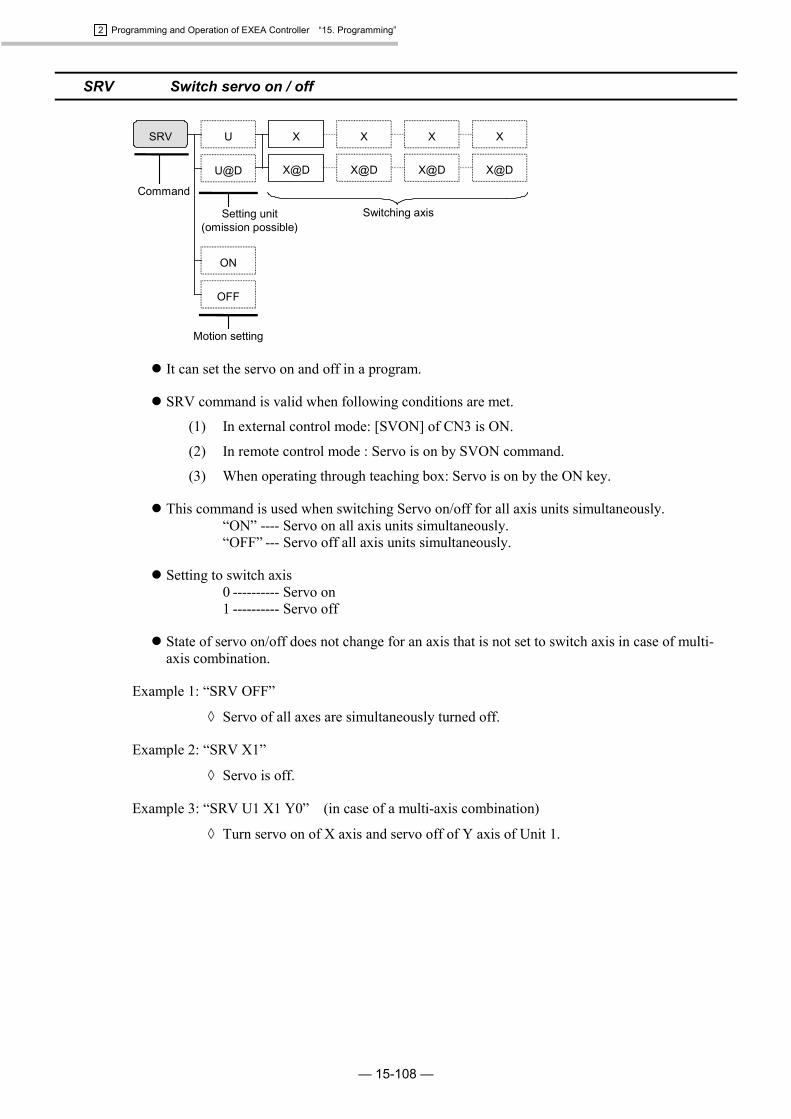
2 Programming and Operation of EXEA Controller “15. Programming”
— 15-108 —
SRV Switch servo on / off
Setting unit(omission possible)
SRV U
U@D
X X X X
Command
X@D X@D X@D X@D
Motion setting
ON
OFF
Switching axis
� It can set the servo on and off in a program.
� SRV command is valid when following conditions are met.
(1) In external control mode: [SVON] of CN3 is ON.
(2) In remote control mode : Servo is on by SVON command.
(3) When operating through teaching box: Servo is on by the ON key.
� This command is used when switching Servo on/off for all axis units simultaneously.“ON” ---- Servo on all axis units simultaneously.“OFF” --- Servo off all axis units simultaneously.
� Setting to switch axis0 ---------- Servo on1 ---------- Servo off
� State of servo on/off does not change for an axis that is not set to switch axis in case of multi-axis combination.
Example 1: “SRV OFF”
� Servo of all axes are simultaneously turned off.
Example 2: “SRV X1”
� Servo is off.
Example 3: “SRV U1 X1 Y0” (in case of a multi-axis combination)
� Turn servo on of X axis and servo off of Y axis of Unit 1.

2 Programming and Operation of EXEA Controller “15. Programming”
— 15-109 —
TAG Set tag
TAGT character
string
Command Tagged name
� Set a tagged name in a program.
� It is to set a mark to be used for a “jump” or a “call” command. Set the tag in 8 characters ofalphabets and numbers. [“_” (under bar) is not included in the characters.] You cannot duplicatethe same tag name in the same program.
Example: “TAG_START”
� Name the tag “_START.”
TCH Substitute current coordinate data for a specified data.
TCH U
U@D
P
P@D
X
X@D
X
X@D
Y
Y@D
Z
Z@D
R
R@D
PX
=
U
U@D
=
PX@D
D
Command
Set data(being substituted)
Set unit(omission permissible)
Switch axis
� This is to set the current position data of specified unit to a specific point register or dataregister.
� Switch axis“0” ------- Sets no action (××××.××).“1” ------- Sets current position.
� Set only the coordinate data of specified axis unit, while the coordinate data of other axis unitsare not changed in case of a multi-axis combination.
Example 1: “TCH P0000 = U1 X1 Z0”
� Substitute current position of motion unit 1 for point register P0000. Apply currentcoordinate data of X axis and none for Z axis, (××××.××). No changes of coordinatesof Y and R axes.
� Normally plural axis units are processed simultaneously in a multi-axis combination. However,when the data register is set as a substitution, processing shall be made to the axis units one byone.
Example 2: “TCH PY@D003 = X1”
� Substitute the current position of X axis of specified unit for Y coordinate of pointregister D003. Other axes remain same.

2 Programming and Operation of EXEA Controller “15. Programming”
— 15-110 —
� Initialization of point register in a program is possible when switching axis is set to “0 (zero)”(no motion).
� In a single axis system only X axis may be specified. It does not specify the unit.
Example 3: “TCH P0000 = X1”
� Get current X coordinate data of point register P0000.
Example 4: “TCH P@D003”
� Set current position of X axis to a point register indicated by D003.
� You can initialize point registers if the axis switch is set to “0” (no action)
Example 5: “TCH P000 = X0” (in case of a single axis system)
� Initialize (××××.××) an X coordinate data in a point registered P000.
Example 6: “TCH P0000 = X0, Y0, Z0, R0 (in case of a single axis system)
� Initialize (××××.××) coordinate data of X to R axes in the point register P000.
TIM Set timer
TIM #Numeric
DCommand
Waiting time
� Program proceeds to the next step after waiting for a time set by the command.
� Time setting range is 0.01 to 999.99 seconds.
Example: “TIM #1.23”
� Stop operation sequence for 1.23 seconds.

2 Programming and Operation of EXEA Controller “15. Programming”
— 15-111 —
TYP Set motion format
TYP U
U@D
& motionformat
Command
Set unit.(omission possible)
Set motion format.
� Set motion format of a specified motion unit.
� Motion formats set by TYP command will be effective in the commands without motion format,which come under the TYP command in the same program.
� Followings show the initial setting of motion format at the starting of a programmed operation.Set the format only that needs a change.
In case of a single axis system : &ASFWL (absolute coordinates, smoothmodified sine accel/decel. FIN on, normalprocessing and interpolation)
In case of a multi-axis combination : &ASFWBL (absolute coordinates, smoothmodified sine accel./decel. FIN on, normalprocessing, no turnout position, no linearinterpolation)
� To make TYP command effective, one or more motion formats shall be set.
� Refer to “15.2.7.1. 12 Motion format of unit.”
� Motion format must be set in the order of A/I ���� T/S ���� F/N ���� W/P ���� B/E* ���� L/H.A/I-------- Absolute / relative coordinatesT/S ------- Fixed. Either setting of T or S gives smooth modified sine accel / decelerationF/N------- FIN on / offW/P ------ Normal processing / Parallel processing
* B/E------- Turnout on / offL/H------- Linear interpolation on / off
* B/E is not available for a single axis system.
Example 1: “TYP &ASFPL” (in case of a single axis system)
� Set the motion formats as:(1) Absolute coordinates (2) Smooth modified sine acceleration/deceleration(3) FIN on (4) Normal processing(5) Linear interpolation
Example 2: “TYP U3 & ASFPEL” (in case of a multi-axis combination)
� Set the motion format of Unit 3 as :(1) Absolute coordinates (2) Smooth modified sine acceleration/deceleration(3) FIN on (4) Normal processing(5) Turnout position (6) Interpolation

2 Programming and Operation of EXEA Controller “15. Programming”
— 15-112 —
UNT Set motion unit [Multi-axis controller]
UNT U number (1 ~ 8)
U@DCommand
Set unit.
� Sets a motion unit number,
� When the unit setting is omitted to the commands which come after this command in the sameprogram, the unit set by UNT is valid for the respective commands.
� When this command is not set, the number U1 is initially set.
� Unit number for each axis may be set in initial setting. Refer to “9.5. Parameters for UnitSetting.”
(1) Initial setting
Module main unitY axis unit of UNT1.
X axis unit of UNT1.
EXEA controller
(2) Set X axis to UNT1 and UNT2.
Module main unit
X axis unit of UNT1.
X axis unit of UNT2.EXEA controller
Example 1: “UNT U3”
� Set Unit 3 as a motion unit.
Example 2: “UNT U@D001”
� Set contents of data register D001 to a motion unit.

2 Programming and Operation of EXEA Controller “15. Programming”
— 15-113 —
WAIT Wait
IB
IB@D
OB
OB@D
IB
IB@D
OB
OB@D
D
Inputpattern 1
ON
OFF
(1) To (2)
WAIT D D
IP
PX
PX@D
PX
PX@D
#Numeric
IP@D
OP
OP@D
IP
IP@D
OP
OP@D
D
To (1)
EQ
NE
GE
GT
LE
LT
(2)
D
#NumericCommand
Data (1) Data (2)
Time-outTime
(omissionpossible)
Inputpattern 8
� This command holds to execute the next step in the middle of a programmed operation whilecomparison of two data (data1 and data2) meets a specified condition.
� When a time for time-out is set behind the condition, the sequence goes to next step when timeexpires even the condition is still maintained.
� It is possible to make a branch instruction just after the time-out is effective by setting JEQcommand to the next step as the judging condition flag [ = ] is set when time expires. Settingrange of time is 0.01 to 9999.99 seconds.
* If the time-out is not set, the system interrupts the sequence when ‘Hold’ or ‘Cyclestop’ is requested during confirming the condition.
� Provided that right side is data 1 and left side is data 2:“EQ”----- Wait if (data 1 = data 2).“NE”----- Wait if (data 1 ��data2).“GE”----- Wait if (data 1 ��data 2).“GT”----- Wait if (data 1 > data 2).“LE” ----- Wait if (data 1 ��data 2).“LT” ----- Wait if (data 1 < data 2)
Example: “WAIT D003 #001.00 EQ #10.00”
� It waits while contents of data register D003 and 0001.00 is “EQ”. Time-out setting is10 seconds.
� Input patternInput pattern 8 ------Input pattern is 8 bit. (Refer to 15.2.7.1. 8 .)Input pattern 1 ------Input pattern is 1 bit. ( 0 is off and 1 is on.)

2 Programming and Operation of EXEA Controller “15. Programming”
— 15-114 —
15.3. Examples of Program
15.3.1. MOV Command : Single Axis System
Outline of motion: Move to a point (0.00, absolute coordinates) from current position (anyposition)Move to (100.00, absolute coordinates) and return to (0.00, absolutecoordinates)
Figure 15-68: Outline of motion
P0000 (0.00)Origin
X axis absolute coordinates (mm)100.00
P0001 (100.00)
Example 1: Direct position setting
Advise: It is possible to program intuitively.
Program Description<Initialize: Home return>
MOV X0000.00 S0100.0A0.5 B0.5 &A
Move to 0.00 (mm) (absolute coordinates) from the current position (any position).(Speed: 100 mm/sec, acceleration / deceleration: 0.5 m/s2, absolute coordinates)<Set parameters of linear motion.>
SPD S0600.0 A5.0 B5.0 Set motion speed and acceleration /deceleration to be used in MOV commandshereafter.(Speed: 600 mm/s, acceleration / deceleration: 5.0 m/s2)
TYP &A Set motion format for MOV commands to be used hereafter. (absolute coordinates)<Linear motion>
MOV X0100.00 Move X axis to 0100.00 (mm).MOV X0000.00 Move X axis to 0000.00 (mm).
<End of motion>END CSTP
Example 2: Set positions to point registers.
Advise: It makes easier to handle the coordinates data after the programming because thecoordinates data becomes independent as the point register.
Set point data:P000 X0000.00P001 X0100.00
Program Description<Initialize: Move to a point P0000.>
MOV P0000 S0100.0 A0.5B0.5 &A
Move to 0.00 (mm) (absolute coordinates) from the current position (any position).(Speed: 100 mm/sec, acceleration / deceleration: 0.5 m/s2, absolute coordinates)<Set parameters of linear motion.>
SPD S0600.0 A5.0 B5.0 Set motion speed and acceleration /deceleration to be used in MOV commandshereafter.(Speed: 600 mm/s, acceleration / deceleration: 5.0 m/s2
TYP &A Set motion format for MOV commands to be used hereafter. (absolute coordinates)<Linear motion>
MOV P0001 Move to the point P0001.MOV P0000 Move to the point P0000.
<End of motion>END CSTP

2 Programming and Operation of EXEA Controller “15. Programming”
— 15-115 —
Example 3: Set positions to point registers in the relative coordinates.
Advise: It makes easier to handle the coordinate data after the programming because thecoordinate data becomes independent as the point register.
Set point data:P0000 X0000.00P0001 X0100.00
Program Description<Initialize: Move to a point P0000.>
MOV P0000 S0100.0 A0.5B0.5 &A
Move to P0000 (absolute coordinates) from the current position (any position).(Speed: 100 mm/sec, acceleration / deceleration: 0.5 m/s2, absolute coordinates)<Set parameters of linear motion.>
SPD S0600.0 A5.0 B5.0 Set motion speed and acceleration /deceleration to be used in MOV commandshereafter.(Speed: 600 mm/s, acceleration / deceleration: 5.0 m/s2)
TYP &I Set motion format for MOV commands to be used hereafter. (relative coordinates)<Linear motion>
MOV P0001 Move the distance in relative coordinates obtained from the point P0001 data.MOV P0000 &A Move to the point P0000.
<End of motion>END CSTP
Example 4: Set positions to point registers, then set indirectly point registers to be used.
Advise: It will make the program for repetitive motion in less codes.Also it will make easier to handle the coordinates data after programming as thecoordinates data becomes independent as the point register.
Set point data:P0000 X0000.00P0001 X0100.00
Program Description<Initialize: Move to a point P0000.>
MOV P0000 S0100.0 A0.5B0.5 &A
Move to 0.00 (mm) (absolute coordinates) from the current position (any position).(Speed: 100 mm/sec, acceleration / deceleration: 0.5 m/s2, absolute coordinates)<Set parameters of linear motion.>
SPD S0600.0 A5.0 B5.0 Set motion speed and acceleration /deceleration for to be used in MOV commandshereafter.(Speed: 600 mm/s, acceleration / deceleration: 5.0 m/s2)
TYP &A Set motion format for MOV commands to be used hereafter. (absolute coordinates)LD D000 = #1 Substitute numeric value 1 for the data register D000.
<Linear motion>MOV P@D000 The motion follows the contents of point register number which is referred to the data
register D000.MOV P0000 Move to the point P0000.
<End of motion>END CSTP

2 Programming and Operation of EXEA Controller “15. Programming”
— 15-116 —
15.3.2. MOV Command in Two Axes Motion
Outline of motion: Move to a point (0.00, 0.00, absolute coordinates) from current position(any position).
(1) Move to (100.00, 0.00, absolute coordinates) then return to (0.00, 0.00, absolute coordinates).
(2) Move to (0.00, 90.00, absolute coordinates), then return to (0.00, 0.00, absolute coordinates).
(3) Move to (100.00, 90.00, absolute coordinates), then move to (0.00, 0.00, absolute coordinates).
Figure 15-69: Outline of motion
P0000 (0.00, 0.00)
Origin X axis absolutecoordinate (mm)
Y axis absolutecoordinate (mm)
100.00
90.00
(1)
(2) (3)
P0001 (100.00, 0.00)
P0002 (0.00, 90.00) P0003 (100.00, 90.00)
Example 1: When specify the position directly
Advice: It is possible to program intuitively.
Program Description<Initialize: Home return>
MOV X0000.00 Y0000.00
S0100.0 A0.5 B0.5 &A
Move to (0, 0. Absolute coordinates) from current position (any coordinates position).(Resultant speed: 100 mm/s, acceleration and deceleration: 0.5 m/s2)<Set parameters for interpolation.>
SPD S0600.0 A5.0 B5.0 Set motion speed, acceleration and deceleration that will be used in interpolation hereafter.(Resultant speed: 600 mm/s, acceleration and deceleration: 5.0 m/s2)
TYP &A Set the motion format for the interpolating commands hereafter. (Absolute coordinates)<Interpolation (1)>
MOV X0100.00 Move X axis only to 0100.00 (mm).MOV X0000.00 Move X axis only to 0000.00 (mm).
<Interpolation (2) >MOV Y0090.00 Move Y axis only to 0090.00 (mm)MOV Y0000.00 Move Y axis only to 0000.00 (mm)
<Interpolation (3)>MOV X0100.00 Y0090.00 Move to the position (100, 90) on absolute coordinates.MOV X0000.00 Y0000.00 Move to the position (0, 0) on absolute coordinates.
<End of motion.>END CSTP

2 Programming and Operation of EXEA Controller “15. Programming”
— 15-117 —
Example 2: When specify the position by the point register
Advice: It makes easier to handle the coordinate data after the programming as the point registermakes coordinate data independent.
Set point data:P0000 X0000.00 Y0000.00 Z××××.×× R××××.××P0001 X0100.00 Y××××.×× Z××××.×× R××××.××P0002 X××××.×× Y0090.00 Z××××.×× R××××.××P0003 X0100.00 Y0090.00 Z××××.×× R××××.××
Program Description<Initialize: Move to P0000.>
MOV P0000 S0100.0 A0.5B0.5 &A Move to P0000 from current position (any coordinates position).
(Resultant speed: 100 mm/s, acceleration and deceleration: 0.5 m/s2)<Set parameters for interpolation.>
SPD S0600.0 A5.0 B5.0 Set motion speed, acceleration and deceleration that will be used in interpolation hereafter.(Resultant speed: 600 mm/s, acceleration and deceleration: 5 m/s2)
TYP &A Set motion format for the interpolating commands hereafter. (Absolute coordinates)<Interpolation (1)>
MOV P0001 Move to the point P0001.MOV P0000 Move to the point P0000.
<Interpolation (2) >MOV P0002 Move to the point P0002.MOV P0000 Move to the point P0000.
<Interpolation (3)>MOV P0003 Move to the point P0003.MOV P0000 Move to the point P0000.
<End of motion.>END CSTP
� The motion changes as shown in Figure 15-70 if P0000 is changed to the position described below.
P0000 X0030.00 Y0020.00 Z××××.×× R××××.××
Figure 15-70: Outline of motion
30.00 100.0
20.00
90.00
(1)
(2) (3)
P0001
P0002 P0003 (100.00, 90.00)
P0000 (30.00, 20.00)
OriginX axis absolutecoordinate (mm)
Y axis absolutecoordinate (mm)
* Coordinate data ××××.×× denotes that it does not change. (does not move.)As Y coordinate of point P0001 is ××××.××, Y coordinate remains 20 mm, the coordinateof point (P0000) before make the motion.

2 Programming and Operation of EXEA Controller “15. Programming”
— 15-118 —
Example 3: Specify positions by point register in relative coordinates format.
Advice: It makes easier to handle the coordinates data after the programming as the pointregister makes coordinates data independent.
Set point data:P0000 X0000.00 Y0000.00 Z××××.×× R××××.××P0001 X0100.00 Y××××.×× Z××××.×× R××××.××P0002 X××××.×× Y0090.00 Z××××.×× R××××.××P0003 X0100.00 Y0090.00 Z××××.×× R××××.××
Program Description<Initialize: Move to P0000.>
MOV P0000 S0100.0 A0.5
B0.5 &A
Move to P0000 from current position (any coordinates position)(Resultant speed: 100 mm/s, acceleration and deceleration: 0.5 m/s2, in absolute coordinatesformat)<Set parameters for interpolation.>
SPD S0600.0 A5.0 B5.0 Set motion speed, acceleration and deceleration that will be used in interpolation hereafter.(Resultant speed: 600 mm/s, acceleration and deceleration: 5 m/s2)
TYP &I Set motion format for the interpolating commands hereafter. (Relative coordinates)<Interpolation (1)>
MOV P0001 Move the distance in relative coordinate format obtained from the data of P0001.MOV P0000 &A Move to the point P0000.
<Interpolation (2) >MOV P0002 Move the distance in relative coordinate format obtained from the data of P0002.MOV P0000 &A Move to the point P0000.
<Interpolation (3)>MOV P0003 Move the distance in relative coordinate format obtained from the data of P0003.MOV P0000 &A Move to the point P0000.
<End of motion.>END CSTP
� The motion changes as shown in Figure 15-71 if P0000 is changed to the position describedbelow.
P0000 X0030.00 Y0020.00 Z××××.×× R××××.××
Figure 15-71: Outline of motion
(1)
(2) (3)
OriginX axis absolutecoordinate (mm)
Y axis absolutecoordinate (mm)
30.00 130.00
20.00
110.00
P0001
P0003P0002
P0000 (30.00, 20.00)
* As MOV P0001 is a motion in relative coordinate format, X coordinate of P0001aftermotion is 130 mm, the addition of X coordinate 30.00 mm of current position P0000 andthe X teaching coordinate 100.00 mm of point P0001.

2 Programming and Operation of EXEA Controller “15. Programming”
— 15-119 —
Example 4: Specify the positions to point registers, then specify the using pointregister indirectly.
� Refer to “Figure 15-69: Outline of motion.”
Advice: It will make the program for repetitive motion in less code, and make easier to handlethe coordinates after the programming as the point register makes coordinates dataindependent.
Set point data:P0000 X0000.00 Y0000.00 Z××××.×× R××××.××P0001 X0100.00 Y××××.×× Z××××.×× R××××.××P0002 X××××.×× Y0090.00 Z××××.×× R××××.××P0003 X0100.00 Y0090.00 Z××××.×× R××××.××
Program Description<Initialize: Move to P0000,>
MOV P0000 S0100.0 A0.5
B0.5 &A
Move to the absolute coordinate position ( 0, 0. Origin) from current position (any coordinateposition).(Resultant speed: 100 mm/s, acceleration and deceleration: 0.5 m/s2, in absolute coordinateformat )<Set parameters for interpolation.>
SPD S0600.0 A5.0 B5.0 Set motion speed, acceleration and deceleration that will be used in interpolation hereafter.(Resultant speed: 600 mm/s, acceleration and deceleration: 5 m/s2)
TYP &A Set motion format for the interpolating commands hereafter. (Absolute coordinates)LD D000 = #1 Substitute numeric number 1 for a data register D000.
<Interpolation (1) to (3)>REP #3 Repeat three times between REP to NXT.MOV P@D000 Movement follows the contents of point number referred by data register D000.MOV P0000 Move to the point P0000.CAL D000 = D000 + #1 Add one to the number of point register to be referred.
(Add 1 to the data register D000.)NXT Return to the REP #3. (start of repetition)
<End of motion.>END CSTP

2 Programming and Operation of EXEA Controller “15. Programming”
— 15-120 —
15.3.3. ARC Command in Two Axes Motion
Motion outline: Move to the absolute coordinate position (0.00, 0.00) from current position(any point)
(1) Move to an absolute coordinate position (90.00, 90.00).
(2) Execute a circular arc interpolation. .Starting point: (90.00, 90.00)Passing point: (111.21, 90.00)Ending point: (111.21, 68.79)
(3) Move to an absolute coordinate position (90.00, 47.57).
Figure 15-72: Outline of motion
(1)
(2)
(3)
OriginX axis absolutecoordinate (mm)
Y axis absolutecoordinate (mm)
90.00
90.00 P0003 (111.21, 90.00)
P0000 (0.00, 0.00)
P0004 (111.21, 68.79)
r=15
P0005 (90.00, 47.57)47.57
P0001 = P0002 (90.00, 90.00)
Example 1: Circular arc interpolation on absolute coordinate(Setting of starting point P0002 may be omitted in the absolutecoordinate format.)
Set point data:P0000 X0000.00 Y0000.00 Z××××.×× R××××.××P0001 X0090.00 Y0090.00 Z××××.×× R××××.××P0003 X0111.21 Y0090.00 Z××××.×× R××××.××P0004 X0111.21 Y0068.79 Z××××.×× R××××.××P0005 X0090.00 Y0047.57 Z××××.×× R××××.××
Program Description<Initialize: Move to P0000.>
MOV P0000 S0100.0 A0.5B0.5 &A
Move to P0000 from current position (any coordinates position).(Resultant speed: 100 mm/s, acceleration and deceleration: 0.5 m/s2, absolute coordinateformat)<Set parameters for interpolation.>
SPD S0600.0 A5.0 B5.0 Set motion speed, acceleration and deceleration that will be used in interpolation hereafter.(Resultant speed: 600 mm/s, acceleration and deceleration: 5 m/s2)
TYP &A Set motion format for the interpolating commands hereafter. (Absolute coordinates)<Interpolation (1): Linear interpolation>
MOV P0001 Move to the point P0001.<Interpolation (2): Circular arc interpolation >
ARC P0003 P0004 Execute circular arc interpolation with passing the point P0003 and ending at the point P0004.(The start point is omitted.)<Interpolation (3): Linear interpolation>
MOV P0005 Move to the point P0005.<End of motion.>
END CSTP

2 Programming and Operation of EXEA Controller “15. Programming”
— 15-121 —
Example 2: Change coordinate format of linear interpolation to relative coordinatein Example 1.(Setting the start point of circular arc interpolation P0002 is required inrelative coordinate format.)
� Refer to “Figure 15-72: Outline of motion.”
Set point data:P0000 X0000.00 Y0000.00 Z××××.×× R××××.××P0001 X0090.00 Y0090.00 Z××××.×× R××××.××P0002 X0090.00 Y0090.00 Z××××.×× R××××.××P0003 X0111.21 Y0090.00 Z××××.×× R××××.××P0004 X0111.21 Y0068.79 Z××××.×× R××××.××P0005 X-0021.21 Y-0021.22 Z××××.×× R××××.××
Program Description<Initialize: Move to P0000.>
MOV P0000 S0100.0 A0.5
B0.5 &A
Move to P0000 from current position (any coordinate positions).(Resultant speed: 100 mm/s, acceleration and deceleration: 0.5 m/s2, absolute coordinateformat)<Set parameters for interpolation.>
SPD S0600.0 A5.0 B5.0 Set motion speed, acceleration and deceleration that will be used in interpolation hereafter.(Resultant speed: 600 mm/s, acceleration and deceleration: 5 m/s2)
TYP &I Set motion format for the interpolating commands hereafter. (Relative coordinates)<Interpolation (1): Linear interpolation>
MOV P0001 Move the distance in relative coordinate format obtained from the data of P0001.<Interpolation (2): Circular arc interpolation >
ARC P0002 P0003 P0004 Execute circular arc interpolation with P0002, as start point, P0003 as passing point and P0004as ending point. (In relative coordinate format.)<Interpolation (3): Linear interpolation>
MOV P0005 Move the distance in relative coordinate format obtained from data of P000.<End of motion.>
END CSTP

2 Programming and Operation of EXEA Controller “15. Programming”
— 15-122 —
� Motion shown in Figure 15-73 is an example if P0001 is changed as described below.
P0001 X0060.00 Y0060.00 Z××××.×× R××××.××
Figure 15-73: Outline of motion
(1)
(2)
(3)
OriginX axis absolutecoordinate (mm)
Y axis absolutecoordinate (mm)
60.00
60.00
P0000
17.57
P0002P0003
P0004
r=15
P0005
P0001
Note:
� The start point of circular arc interpolation may be omitted in absolute coordinate format.However, the current position (start position), passing point and ending point shall be on thesame circle.
� A circular interpolation in relative coordinate format is an interpolation of which trajectory, thatis defined by the starting position, passing point and ending point in absolute coordinate format,shifts to the current position. The absolute coordinate of the starting point shall be the currentposition.
� The start point cannot be omitted in the relative coordinate format.

2 Programming and Operation of EXEA Controller “15. Programming”
— 15-123 —
15.3.4. CIR Command in Two Axes Motion
Outline of motion: Move to absolute coordinate position (0.00, 0.00) from current position(any coordinate position).
(1) Move to a point (90.00, 90.00, absolute coordinate position)
(2) Execute a circular interpolation in absolute coordinate format with:Start point: (90.00, 90.00)Passing points: (111.12, 90.00) and (111.12, 68.79)
(3) Move to the point (120.00, 120.00) in absolute coordinate format.
Figure 15-74: Outline of motion
(1)
(2)
(3)
OriginX axis absolutecoordinate (mm)
Y axis absolutecoordinate (mm)
90.00
90.00 P0003 (111.21, 90.00)
P0000 (0.00, 0.00)
P0004 (111.21, 68.79)
r=15
P0005 (120.00, 120.00)120.00
P0001 = P0002(90.00, 90.00)
120.00

2 Programming and Operation of EXEA Controller “15. Programming”
— 15-124 —
Example 1: Circular interpolation in absolute coordinate format(Setting starting point of circular interpolation P0002 may be omittedin absolute coordinate format.)
Set point data:P0000 X0000.00 Y0000.00 Z××××.×× R××××.××P0001 X0090.00 Y0090.00 Z××××.×× R××××.××P0003 X0111.21 Y0090.00 Z××××.×× R××××.××P0004 X0111.21 Y0068.79 Z××××.×× R××××.××P0005 X0120.00 Y0120.00 Z××××.×× R××××.××
Program Description<Initialize: Move to P0000.>
MOV P0000 S0100.0 A0.5
B0.5 &A
Move to P0000 from current position (any coordinate position).(Resultant speed: 100 mm/s, acceleration and deceleration: 0.5 m/s2, absolute coordinateformat)<Set parameters for interpolation.>
SPD S0600.0 A5.0 B5.0 Set motion speed, acceleration and deceleration that will be used in a interpolation hereafter.(Resultant speed: 600 mm/s, acceleration and deceleration: 5 m/s2)
TYP &A Set motion format for the interpolating commands hereafter. (Absolute coordinate format)<Interpolation (1): Linear interpolation>
MOV P0001 Move to the point P0001.<Interpolation (2): Circular interpolation >
CIR P0003 P0004 Execute circular arc interpolation with passing the point P0003 and ending at the point P0004.(Specifying the start point is omitted.)<Interpolation (3): Linear interpolation>
MOV P0005 Move to the point P0005.<End of motion.>
END CSTP

2 Programming and Operation of EXEA Controller “15. Programming”
— 15-125 —
Example 2: Change coordinate format of linear and circular interpolation inExample 1 to relative coordinate.(Setting of start point P0002 is required in relative coordinate format.)
� Refer to “Figure 15-74: Outline of motion.”
Set point data:P0000 X0000.00 Y0000.00 Z××××.×× R××××.××P0001 X0090.00 Y0090.00 Z××××.×× R××××.××P0002 X0090.00 Y0090.00 Z××××.×× R××××.××P0003 X0111.21 Y0090.00 Z××××.×× R××××.××P0004 X0111.21 Y0068.79 Z××××.×× R××××.××P0005 X0030.00 Y0030.00 Z××××.×× R××××.××
Program Description<Initialize: Move to P0000.>
MOV P0000 S0100.0 A0.5B0.5 &A
Move to P0000 from current position (any coordinate position).(Resultant speed: 100 mm/s, acceleration and deceleration: 0.5 m/s2, absolute coordinateformat)<Set parameters for interpolation.>
SPD S0600.0 A5.0 B5.0 Set motion speed, acceleration and deceleration that will be used in a interpolation hereafter.(Resultant speed: 600 mm/s, acceleration and deceleration: 5 m/s2)
TYP &I Set motion format for the interpolating commands hereafter. (Relative coordinate format)<Interpolation (1): Linear interpolation>
MOV P0001 Move the distance in relative coordinate format obtained from data of P0001.<Interpolation (2): Circular interpolation >
CIR P0002 P0003 P0004 Execute circular arc interpolation with start point P002 (current position), passing point P0003and ending at the point P0004. (Relative coordinates format)<Interpolation (3): Linear interpolation>
MOV P0005 Move the distance in relative coordinate format obtained from data of point P0005.<End of motion.>
END CSTP
� It is possible to perform the same interpolation when the above point registers are changed asshown below.
P0002 X0000.00 Y0000.00 Z××××.×× R××××.××P0003 X0021.21 Y0000.00 Z××××.×× R××××.××P0004 X0021.21 Y‐0021.00 Z××××.×× R××××.××
Note:
� The start point of circular arc interpolation may be omitted in absolute coordinate format.However, the current position (start position), passing point and ending point shall be on thesame circle.
� A circular interpolation in relative coordinate format is an interpolation of which trajectory, thatis defined by the starting position, passing point and ending point in absolute coordinate format,shifts to the current position. The absolute coordinate of the starting point shall be the currentposition.
� The start point cannot be omitted in the relative coordinates format.
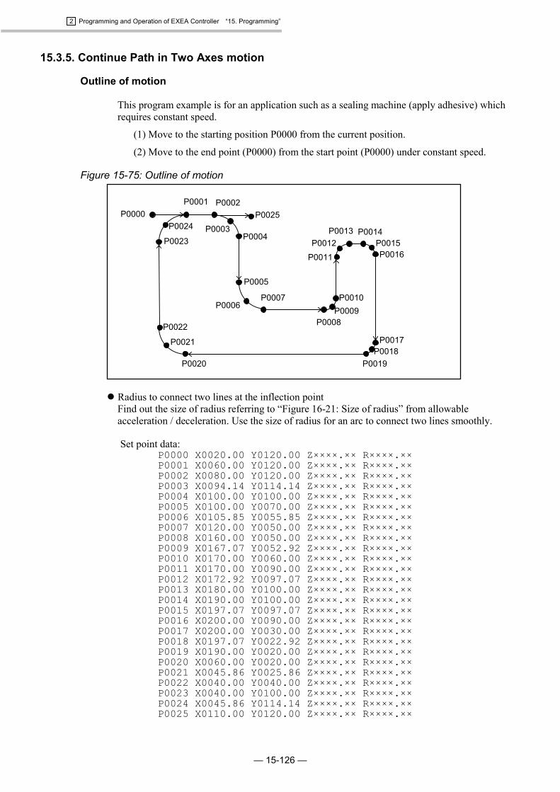
2 Programming and Operation of EXEA Controller “15. Programming”
— 15-126 —
15.3.5. Continue Path in Two Axes motion
Outline of motion
This program example is for an application such as a sealing machine (apply adhesive) whichrequires constant speed.
(1) Move to the starting position P0000 from the current position.
(2) Move to the end point (P0000) from the start point (P0000) under constant speed.
Figure 15-75: Outline of motion
P0002
P0003
P0000
P0004
P0005
P0001
P0006P0007
P0008P0009
P0010
P0011P0012
P0013 P0014P0015P0016
P0017P0018
P0019P0020
P0021
P0022
P0023
P0024P0025
� Radius to connect two lines at the inflection pointFind out the size of radius referring to “Figure 16-21: Size of radius” from allowableacceleration / deceleration. Use the size of radius for an arc to connect two lines smoothly.
Set point data:P0000 X0020.00 Y0120.00 Z××××.×× R××××.××P0001 X0060.00 Y0120.00 Z××××.×× R××××.××P0002 X0080.00 Y0120.00 Z××××.×× R××××.××P0003 X0094.14 Y0114.14 Z××××.×× R××××.××P0004 X0100.00 Y0100.00 Z××××.×× R××××.××P0005 X0100.00 Y0070.00 Z××××.×× R××××.××P0006 X0105.85 Y0055.85 Z××××.×× R××××.××P0007 X0120.00 Y0050.00 Z××××.×× R××××.××P0008 X0160.00 Y0050.00 Z××××.×× R××××.××P0009 X0167.07 Y0052.92 Z××××.×× R××××.××P0010 X0170.00 Y0060.00 Z××××.×× R××××.××P0011 X0170.00 Y0090.00 Z××××.×× R××××.××P0012 X0172.92 Y0097.07 Z××××.×× R××××.××P0013 X0180.00 Y0100.00 Z××××.×× R××××.××P0014 X0190.00 Y0100.00 Z××××.×× R××××.××P0015 X0197.07 Y0097.07 Z××××.×× R××××.××P0016 X0200.00 Y0090.00 Z××××.×× R××××.××P0017 X0200.00 Y0030.00 Z××××.×× R××××.××P0018 X0197.07 Y0022.92 Z××××.×× R××××.××P0019 X0190.00 Y0020.00 Z××××.×× R××××.××P0020 X0060.00 Y0020.00 Z××××.×× R××××.××P0021 X0045.86 Y0025.86 Z××××.×× R××××.××P0022 X0040.00 Y0040.00 Z××××.×× R××××.××P0023 X0040.00 Y0100.00 Z××××.×× R××××.××P0024 X0045.86 Y0114.14 Z××××.×× R××××.××P0025 X0110.00 Y0120.00 Z××××.×× R××××.××
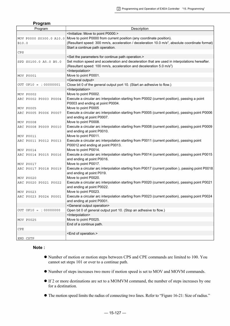
2 Programming and Operation of EXEA Controller “15. Programming”
— 15-127 —
ProgramProgram Description
<Initialize: Move to point P0000.>MOV P0000 S0300.0 A10.0
B10.0
Move to point P0000 from current position (any coordinate position).(Resultant speed: 300 mm/s, acceleration / deceleration 10.0 m/s2, absolute coordinate format)Start a continue path operation.
CPS
<Set the parameters for continue path operation.>SPD S0100.0 A5.0 B5.0 Set motion speed and acceleration and deceleration that are used in interpolations hereafter.
(Resultant speed: 100 mm/s, acceleration and deceleration 5.0 m/s2)<Interpolation>
MOV P0001 Move to point P0001.<General output>
OUT OP10 = ;00000001 Close bit 0 of the general output port 10. (Start an adhesive to flow.)<Interpolation>
MOV P0002 Move to point P0002.ARC P0002 P0003 P0004 Execute a circular arc interpolation starting from P0002 (current position), passing a point
P0003 and ending at point P0004.MOV P0005 Move to point P0005ARC P0005 P0006 P0007 Execute a circular arc interpolation starting from P0005 (current position), passing point P0006
and ending at point P0007.MOV P0008 Move to point P0008.ARC P0008 P0009 P0010 Execute a circular arc interpolation starting from P0008 (current position), passing point P0009
and ending at point P0010.MOV P0011 Move to point P0011.ARC P0011 P0012 P0013 Execute a circular arc interpolation starting from P0011 (current position), passing point
P00012 and ending at point P0013.MOV P0014 Move to point P0014.ARC P0014 P0015 P0016 Execute a circular arc interpolation starting from P0014 (current position), passing point P0015
and ending at point P0016.MOV P0017 Move to point P0017.ARC P0017 P0018 P0019 Execute a circular arc interpolation starting from P0017 (current position ), passing point P0018
and ending at point P019.MOV P0020 Move to point P0020.ARC P0020 P0021 P0022 Execute a circular arc interpolation starting from P0020 (current position), passing point P0021
and ending at point P0022.MOV P0023 Move to point P0023.ARC P0023 P0024 P0001 Execute a circular arc interpolation starting from P0023 (current position), passing point P0024
and ending at point P0001.<General output operation>
OUT OP10 = ;00000000 Open bit 0 of general output port 10. (Stop an adhesive to flow.)<Interpolation>
MOV P0025 Move to point P0025.End of a continue path.
CPE
<End of operation.>END CSTP
Note :
� Number of motion or motion steps between CPS and CPE commands are limited to 100. Youcannot set steps 101 or over to a continue path.
� Number of steps increases two more if motion speed is set to MOV and MOVM commands.
� If 2 or more destinations are set to a MOMVM command, the number of steps increases by onefor a destination.
� The motion speed limits the radius of connecting two lines. Refer to “Figure 16-21: Size of radius.”

2 Programming and Operation of EXEA Controller “15. Programming”
— 15-128 —
15.3.6. Arch Motion in Two Axes Motion
Outline of motion
� Set an upper and lower off-limits boundories and turnout position not to get in the off-limitsarea.
� An arch motion is executed only when starting or ending position of a motion is in the off-limitsarea.
� Effective axis unit for the arch motion commands is Z axis unit only in a multi-axis combination.
Figure 15-76: Outline of motion
X axis
Z axis
Lower off-limits boundary: Escape(Lwr.Z)
Upper off-limits boundary: Escape(Upr.Z)
Turnout position: Escape(Pos.Z)
Start position End position
(50.00, 10.00) (200.00, 10.00)
120.00 (mm)
100.00 (mm)
0.00 (mm)
Example 1: Set off-limits boundary and turnout position directly at the initialsetting
� Specify the off-limits boundary and the turnout position of Z axis at the initial setting.
� Refer to “9.3.4. Parameters for Position and Coordinates” for the setting.
Table 15-3: Setting turnout positionSetting parameter
Escape (upr. Z)Off-limits boundary (Z axis higher limit) :100.00
Escape (lwr. Z)Off-limits boundary (Z axis lower limit) : 0.00
Escape (pos.Z)Turnout position (Z axis position) :120.00
Program Description < Initialize: Move to starting point. >
MOV X0050.00 Z0010.00
S0100.0 A0.5 B0.5Move to a point (50.0, 10.0, in absolute coordinate format) from current position (any position).(Resultant speed: 100 mm /s, acceleration and deceleration: 0.5 m/s2, absolute coordinateformat)< Set the parameters for interpolation.>
SPD S0600.0 A3.0 B3.0 Set motion speed, acceleration and deceleration that are used to the interpolations hereafter.(Resultant speed: 600 mm/s, acceleration and deceleration: 3.0 m/s2)< Arch motion >
MOV X0200.00 &E Move by arch motion to a point (200.0, 10.0 in absolute coordinate format).< End of motion >
END CSTP

2 Programming and Operation of EXEA Controller “15. Programming”
— 15-129 —
Example 2: Setting turnout position in the program
� Use the command (ESCZ) to set “off-limits boundary” of Z axis.
� Refet to “Figure 15-76: Outline of motion.”
Program Description< Initialize: Move to start point. >
MOV X0050.00 Z0010.00
S0100.0 A0.5 B0.5
Move to a point (50.0, 10.0, in absolute coordinate format) from current position (any position).(Resultant speed: 100 mm /s, acceleration and deceleration: 0.5 m/s2, absolute coordinateformat)< Set the parameters for interpolation.>
SPD S0600.0 A3.0 B3.0 Set motion speed, acceleration and deceleration that are used to the interpolations hereafter.(Resultant speed: 600 mm/s, acceleration and deceleration: 3.0 m/s2)<Set parameter of the turnout position.>
ESCZ #0000.00 #0100.00
#0120.00
Set lower off-limits boundary to 0.0 mm, higher boundary to 100.00 mm and turnout position to120.00 mm.<Arch motion >
MOV X0200.00 &E Execute an arch motion to go to a point (200.0, 10.0, in absolute coordinate format).<End of program>
END CSTP
Example 3: Changing the end position
� End position of arch motion can be changed as shown in Figure 15-77 by setting arch motioncommand to the program of the examples above.
MOV X0200.00 &E � MOV X0200.00 Z0050.00 &E
Figure 15-77: Outline of motion
X axis
Z axis
Lower off-limits boundary: Escape(Lwr.Z)
Upper off-limits boundary: Escape(Upr.Z)
Turnout position: Escape(Pos.Z)
Start position
End position
(50.00, 10.00)
(200.00, 50.00)
120.00 (mm)
100.00 (mm)
0.00 (mm)
Note:
� Add an allowance of 10 mm approximately to the setting of off-limits boundary (higher / lower)and confirm that there is no interference with the objects in the off-limits area.
� When upper off-limits boundary and turnout position are too much apart, or acceleration is settoo low, the trajectories of starting and ending of arch motion may not be the same.
� When both start and end points are not in the off-limits area, Z axis moves linearly to the endposition. Be sure to make the start point or end point in the off-limits area.

2 Programming and Operation of EXEA Controller “15. Programming”
— 15-130 —
15.3.7. Palletizing in Two Axes Motion
Outline of motion
� Execute a palletizing motion from P0001 to the positions of 0 to 8 .
Figure 15-78: Outline of motion
X axis
Y axis
P0001 (300.00, 300.00)
(50.00, 0.00)
(0.00, 50.00)0 1 2
3 4 5
6 7 8
Setting palletizing operation
� Use a number 00 as a pallet number in this programming example. Set palletizing operation tothe palletizing operation number 00.
� Refer to “16.1. Palletizing” for details of setting.
[Outline of setting]
� Select the palletizing mode (PAL mode) then select Palletizing operation number 00.
� Enter to EDT mode next, then set the items listed in Table 15-4.
Table 15-4: Setting palletizing motionSetting item Description
Memo (Name of palletizing operation) : DEMO Input “DEMO.”Type (Select positioning pattern of palletizing operation.) : MLT Multiple step positioning patternAxis (Set operating axis) : XX YY Operate X and Y axis.
Start Position (Set start position.) : X0050.00 Y0050.00 Coordinates ( 50, 50) : Position (0)in Figure 15-78.
Width (Set step distance) : X0050.00 Y0050.00 50 mm each, X and Y axisSize (Number of positioning intervals) : X0002 Y0002 Two times, X and Y axis
Move Pattern (Set operation format.) : XNRM X axis takes precedence. Moving toone direction.
Set point data:P0001 X0300.00 Y0300.00 Z××××.×× R××××.××

2 Programming and Operation of EXEA Controller “15. Programming”
— 15-131 —
Program Description<Initialize: Palletizing operation>
PALI QN00 $DEMO Initialize the palletizing operation number 00.<Set repeating motion tag.>
TAG _00
<Interpolation>MOV P0001 S0300.0 Move to a point P0001. (resultant speed 300 mm/s)
<Palletizing operation>PALM QN00 S0300.0 Palletizing operation (resultant speed: 300 mm/s)TIM #0001.00 Timer: 1 second
<Get palletizing status.>QSTS D000 = QN00 QPC Substitute next point register number of palletizing operation for data register D000.
(* Note: Point register number starts from 0 (zero).<Confirm completion of palletizing operation.>
CMP D000 #0000 JNE _00 Jump to TAG_00 if the numeric number in data register D000 (number of next point register) isnot 0 (zero).<Interpolation>
MOV P0001 S0300.0 Move to a point P0001. (Resultant speed: 300 mm/s)<End of program>
END CSTP
Note:
� Palletizing position number starts from 0 (zero) and increases by one for every execution ofPALM command.
� When the last palletizing operation is completed, the palletizing position number returns to 0(zero).

2 Programming and Operation of EXEA Controller “15. Programming”
— 15-132 —
15.3.8. Multitask
15.3.8.1. Example of Program 1
Outline of motion
� Executes repetitive interpolation starting from current position.Repeat linear interpolation to the destination point (120.00, 110.00)Repeat linear interpolation to the destination (000.00, 000,00)
� Closes Bit 0 of general output port OP 10 when bit 0 of general input port IP10 is ON in themiddle of the interpolation.
� Opens Bit 0 of general output port OP10 when bit 0 of general input port IO10 is off in themiddle of the interpolation.
Figure 15-79: Outline of motion
OriginX axis absolutecoordinate (mm)
Y axis absolutecoordinate (mm)
120.00
110.00 (120.00, 110.00)

2 Programming and Operation of EXEA Controller “15. Programming”
— 15-133 —
Example 1: Set parallel processing as a motion format to MOV command
Interpolation
Module main unitGeneral input
General output
Task 1 Task 2
Get state of input port.
Output to output port.
One set of program
Program Description<Initialize>
LD D001 = #1 Set the flag to switch “go” and “return” of interpolation.(#-1: go, #1 return)Interpolation
TAG _LOOP
MSTS D000 = X Y Read out state of interpolation:(#0: stopping #1: moving)
CMP D000 #0 JNE _OUTPUT Output when started interpolation is not completed.CAL D001 = D001 * #-1 Switch the flag for “go and return” motion.CMP D001 #1 JEQ _LOCUS2 Switch to “return” the interpolation.
<Interpolation “go”>TAG _LOCUS1
MOV X0120.00 Y0110.00 &P Outputs to start the interpolation as the parallel processing motion.JMP _OUTPUT
<Interpolation “return”>TAG _LOCUS2
MOV X0000.00 Y0000.00 &P Outputs to start the interpolation as the parallel processing motion.<Output>
TAG _OUTPUT
OUT OB100 = IB100 Output the state of bit 0 of general input port IP10 to bit0 of general output OP10.JMP _LOOP
END CSTP

2 Programming and Operation of EXEA Controller “15. Programming”
— 15-134 —
Example 2: Divide into main sequence and sub-sequence
Interpolation
Module main unitGeneral input
General output
Main sequence Sub-sequence
Input from input port.
Output to output port.
Main sequence: Output to I/O port.
Program Description<Sub-sequence>
CHLD $LOCUS Start sub-sequence $LOCUS.<Output>
TAG _LOOP
OUT OB100 = IB100 Output the state of bit0 of general input port IP10 to bit 0 of general output port OP10.JMP _LOOP Jump to TAG_LOOP. (Repeat)END CSTP
Sub-sequence (Name of program: $LOCUS): Only operates interpolation.
Program Description<Interpolation>
TAG _LOOPMOV X0120.00 Y0110.00 Linear interpolationMOV X0000.00 Y0000.00 Linear interpolationJMP _LOOP Jump to TAG_LOOP. (Repeat)ENDC
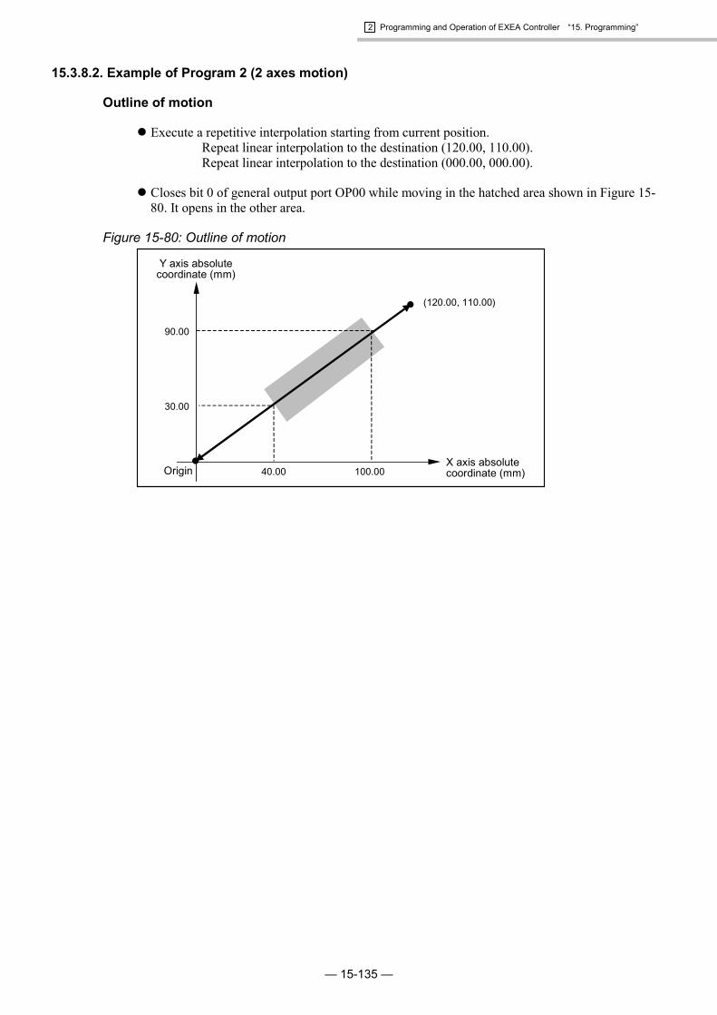
2 Programming and Operation of EXEA Controller “15. Programming”
— 15-135 —
15.3.8.2. Example of Program 2 (2 axes motion)
Outline of motion
� Execute a repetitive interpolation starting from current position.Repeat linear interpolation to the destination (120.00, 110.00).Repeat linear interpolation to the destination (000.00, 000.00).
� Closes bit 0 of general output port OP00 while moving in the hatched area shown in Figure 15-80. It opens in the other area.
Figure 15-80: Outline of motion
OriginX axis absolutecoordinate (mm)
Y axis absolutecoordinate (mm)
40.00 100.00
30.00
90.00
(120.00, 110.00)

2 Programming and Operation of EXEA Controller “15. Programming”
— 15-136 —
Example 1: Specify a parallel processing as a motion format to MOV command
Interpolation
General output
Task 1 Task 2
Check current position.Judging area
Output to output port.
One set of program
Module main unit
Program Description<Initialize>
LD D001 = #1 Set the flag to switch “go” and “return” of interpolation.(#-1: go, #1 return)
LD P0100 = X0040.00 Y0030.00 Store the coordinate data of area judging to P0100 and P0101.LD P0101 = X0100.00 Y0090.00
<Interpolation and judging area>TAG _LOOP
MSTS D000 = X Y Get information on the state of interpolation:(#0: stopping #1: moving)
CMP D000 #0 JNE _JUDGE Execute judging area when motion of interpolation is notcompleted.
CAL D001 = D001 * #-1 Switch the flag for “go and return” motion.CMP D001 #1 JEQ _LOCUS2 Switch the interpolation to “return.”
<Interpolation “go”>TAG _LOCUS1
MOV X0120.00 Y0110.00 &P Outputs to start the interpolation as the parallel processing motion.JMP _JUDGE Judging area
<Interpolation “return”>TAG _LOCUS2
MOV X0000.00 Y0000.00 &P Start interpolation as a parallel processing.<Area judging>
TAG _JUDGE
TCH P0000 = X1 Y1 Store current position to P0000.CMP PX0000 PX0100 JLT _OUTRNG
CMP PY0000 PY0100 JLT _OUTRNG Is current position in the area ?CMP PX0000 PX0101 JGT _OUTRNG (If not, jump to TAG_OUTRNG.)CMP PY0000 PY0101 JGT _OUTRNG
<Output result>TAG _INRNG In case of “in the area”:OUT OB100 = ;1 Close bit 0 of general output port OP10.JMP _LOOP Jump to TAG_LOOP. (Repeat)TAG _OUTRNG In case of “out of area”:OUT OB100 = ;0 Open bit 0 of general output port OP10.JMP _LOOP Jump to TAG_LOOP. (Repeat)END CSTP

2 Programming and Operation of EXEA Controller “15. Programming”
— 15-137 —
Example 2: Divide into main sequence and sub-sequence
Interpolation
General output
Main sequence 1 Sub-sequence
Check current position.Judging area
Output to output port.
Module main unit
Main sequence: Judge the area and output to I/O
Program Description<Initialize>
LD P0100 = X0040.00 Y0030.00 Store coordinate data of area judging to P0100 and P00101.LD P0101 = X0100.00 Y0090.00
<Start sub-sequence.>CHLD $LOCUS Start sub-sequence $LOCUS.
<Judging area>TAG _LOOP
<Check current position>TCH P0000 = X1 Y1 Store current position to P0000.CMP PX0000 PX0100 JLT _OUTRNG
CMP PY0000 PY0100 JLT _OUTRNG Is current position in the area ?CMP PX0000 PX0101 JGT _OUTRNG (If not, jump to TAG_OUTRNG.)CMP PY0000 PY0101 JGT _OUTRNG
<Output result>TAG _INRNG In case of “in the area”:OUT OB100 = ;1 Close bit 0 of general output OP10.JMP _LOOP Jump to TAG_LOOP. (Repeat)TAG _OUTRNG In case of “out of area”:OUT OB100 = ;0 Open bit 0 of output port OP10.JMP _LOOP Jump to TAG_LOOP. (Repeat)END CSTP
Sub-sequence (Name of sub-sequence: $LOCUS): Only operates interpolation.
Program Description<Interpolation>
TAG _LOOP
MOV X0120.00 Y0110.00 Linear interpolationMOV X0000.00 Y0000.00 Linear interpolationJMP _LOOP Jump to TAG_LOOP. (Repeat)ENDC
Note:
� Outputted position signal includes some errors against actual position as the judging area in thisprogram is done by polling.

2 Programming and Operation of EXEA Controller “15. Programming”
— 15-138 —
(Blank Page)

2 Programming and Operation of EXEA Controller “16. Description of Function”
— 16-1 —
16. Description of Function16.1. Palletizing (Multi-axis combination only)
16.1.1. Outline of Palletizing Operation
� It is possible to select a setting format of palletizing positions from those described below.
� Multiple regular interval format : Palletizing positions are set by the points at equalintervals on X and Y coordinate axes of a pallet.
� Divided sides format : Palletizing positions are set by the points on X and Ycoordinate axes at divided positions by specifiednumbers on the pallet sides .
� Three corners format : Palletizing positions are determined by the positionsof three corners of the pallet.
� Palletizing positions are on a two dimensional flat surface defined by X and Y coordinate axes.
Figure 16-1: Palletizing
� X axis
Y axis
m4321
2
3
4Point P000
↑n
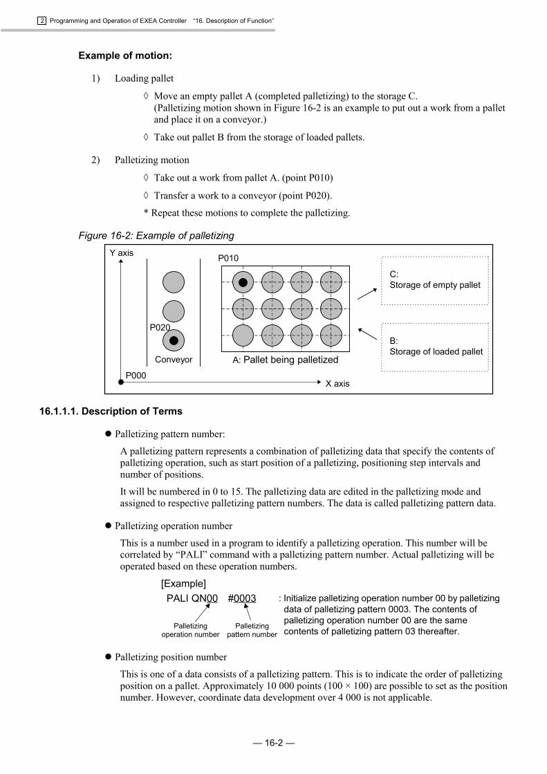
2 Programming and Operation of EXEA Controller “16. Description of Function”
— 16-2 —
Example of motion:
1) Loading pallet
� Move an empty pallet A (completed palletizing) to the storage C.(Palletizing motion shown in Figure 16-2 is an example to put out a work from a palletand place it on a conveyor.)
� Take out pallet B from the storage of loaded pallets.
2) Palletizing motion
� Take out a work from pallet A. (point P010)
� Transfer a work to a conveyor (point P020).
* Repeat these motions to complete the palletizing.
Figure 16-2: Example of palletizing
C: Storage of empty pallet
B: Storage of loaded pallet
Y axis
X axis
A: Pallet being palletizedConveyor
P020
P010
P000
16.1.1.1. Description of Terms
� Palletizing pattern number:
A palletizing pattern represents a combination of palletizing data that specify the contents ofpalletizing operation, such as start position of a palletizing, positioning step intervals andnumber of positions.
It will be numbered in 0 to 15. The palletizing data are edited in the palletizing mode andassigned to respective palletizing pattern numbers. The data is called palletizing pattern data.
� Palletizing operation number
This is a number used in a program to identify a palletizing operation. This number will becorrelated by “PALI” command with a palletizing pattern number. Actual palletizing will beoperated based on these operation numbers.
PALI QN00 #0003
[Example]: Initialize palletizing operation number 00 by palletizing
data of palletizing pattern 0003. The contents ofpalletizing operation number 00 are the samecontents of palletizing pattern 03 thereafter.Palletizing
pattern numberPalletizing
operation number
� Palletizing position number
This is one of a data consists of a palletizing pattern. This is to indicate the order of palletizingposition on a pallet. Approximately 10 000 points (100 × 100) are possible to set as the positionnumber. However, coordinate data development over 4 000 is not applicable.
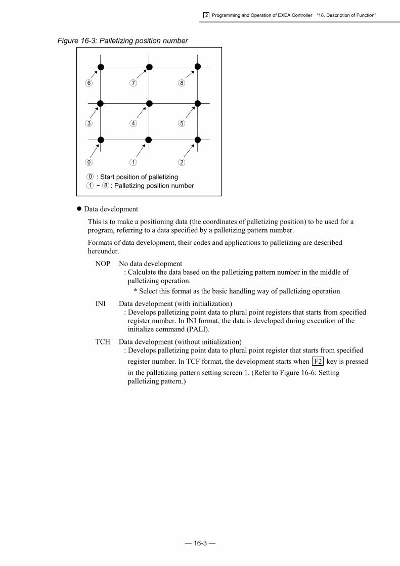
2 Programming and Operation of EXEA Controller “16. Description of Function”
— 16-3 —
Figure 16-3: Palletizing position number
: Start position of palletizing ~ : Palletizing position number
0 1 2
3 4 5
6 7 8
01 8
� Data development
This is to make a positioning data (the coordinates of palletizing position) to be used for aprogram, referring to a data specified by a palletizing pattern number.
Formats of data development, their codes and applications to palletizing are describedhereunder.
NOP No data development: Calculate the data based on the palletizing pattern number in the middle of
palletizing operation.* Select this format as the basic handling way of palletizing operation.
INI Data development (with initialization): Develops palletizing point data to plural point registers that starts from specified
register number. In INI format, the data is developed during execution of theinitialize command (PALI).
TCH Data development (without initialization): Develops palletizing point data to plural point register that starts from specified
register number. In TCF format, the development starts when F2 key is pressedin the palletizing pattern setting screen 1. (Refer to Figure 16-6: Settingpalletizing pattern.)

2 Programming and Operation of EXEA Controller “16. Description of Function”
— 16-4 —
16.1.1.2. Programming Procedure for Palletizing
16.1.1.2. Programming Procedure for Palletizing
� Palletizing program mode:
� In this mode you can set the data for palletizing motion.
� There are several functions for editing the data.
� Naming and adding memo
� Selection of palletizing pattern and changing data
� Copy or delete palletizing number.
� Store the data to the flash memory and read out the data
� Programming of palletizing
� Use the commands related to palletizing and program a palletizing operation.
� Refer to “15.2. Programming” for more detail.
Table 16-1: Program command of palletizingCommand Outline of function
PALI Command to initialize a palletizing operation. The command correlates the data ofspecified palletizing pattern number to a palletizing operation number to make the datausable for a specified unit. Be sure to set the command on the top of a program.
PALL Command to call subroutine. This command calls a subroutine at the end of a palletizingmotion. This command may be used to call a subroutine for loading pallet.
PALE Command to call a subroutine. This command calls a subroutine in the middle ofpalletizing motion. This command is used when loading a pallet is necessary in the middleof a palletizing.
PALM Command to move to a palletizing position of specified palletizing pattern number. Afterthe motion is completed, the palletizing position number increases for one.
PALN Command to change a position number of specified palletizing operation. This commandis used when you want to skip a pallet position.
QSTS This command is to read out palletizing status of a specified pallet number.(When you need to check the next palletizing position number, etc.)
� Refer to “15.3. Example of Program” as well.

2 Programming and Operation of EXEA Controller “16. Description of Function”
— 16-5 —
16.1.2. Outline of Palletizing Program Mode
� There are 7 modes in the palletizing program mode and it is composed in the tree structure asshown in Figure 16-5.
Figure 16-4: Palletizing program mode
: Edits palletizing pattern data.
: Correlates palletizing pattern data to position data.
: Sets palletizing pattern number.
: Clears palletizing pattern number.
: Copies palletizing pattern number.
: Stores palletizing pattern number.
: Reads out stored palletizing pattern number.
Palletizing
Setting process ofpalletizing, screen 1
SAV
CPY
CLR
num
TCH
EDT
LOD
Setting process ofpalletizing, screen 2
Setting process ofpalletizing, screen 3
Figure 16-5: Palletizing program mode list
F1 SAV
Stores data.
F1 CLR
Intializes
F3 num
Specifiespalletizing pattern.
F4
etc
[PAL]
Palletizingprogram mode
Name Edit naming of palletizing operation.Memo Edit memo to palletizing operationType Select palletizing position pattern.Axis Specify operating axis.Start position Set start position.Width Set position intervalX position Set a corner point X.Y position Set a corner point Y.Size Set number of intervals.Move pattern Set operation pattern.Point jump Set jump format.P register Set coordinate data development.
F1 EDT
Edits data
F2 TCH
Correlatesposition data
F2 CPY
Copies.
F2 LOD
Reads out data.
Data development to position data of palletizing.
Specify palletizing pattern number
Clear palletizing pattern data.
Store palletizing pattern data.
Copy palletizing pattern data.
Read out pallet pattern data.

2 Programming and Operation of EXEA Controller “16. Description of Function”
— 16-6 —
16.1.2.1. Screen of Palletizing Program Mode
� The screen as shown below appears when palletizing program mode is selected. It shows settingstate of palletizing data.
� Pallet pattern number is on the first line, name of palletizing operation is on the 2nd line and usermemo is on the 3rd line. Maximum number of characters is 8 for naming and 16 for user memo.
[PAL] 00
$PALNAME
USE RPALET MEMO
1EDT 2TCH 3num 4etc
Palletizing pattern number
Name of palletizing operation
User memo
* When changing palletizing data is attempted during programmed operation (or operation in anymanner), the screen gives message as shown below and the system interrupts the settingpalletizing process.
* This state remains until MODE or SET key is pressed.
[PAL] T*
Err:Disable PAL
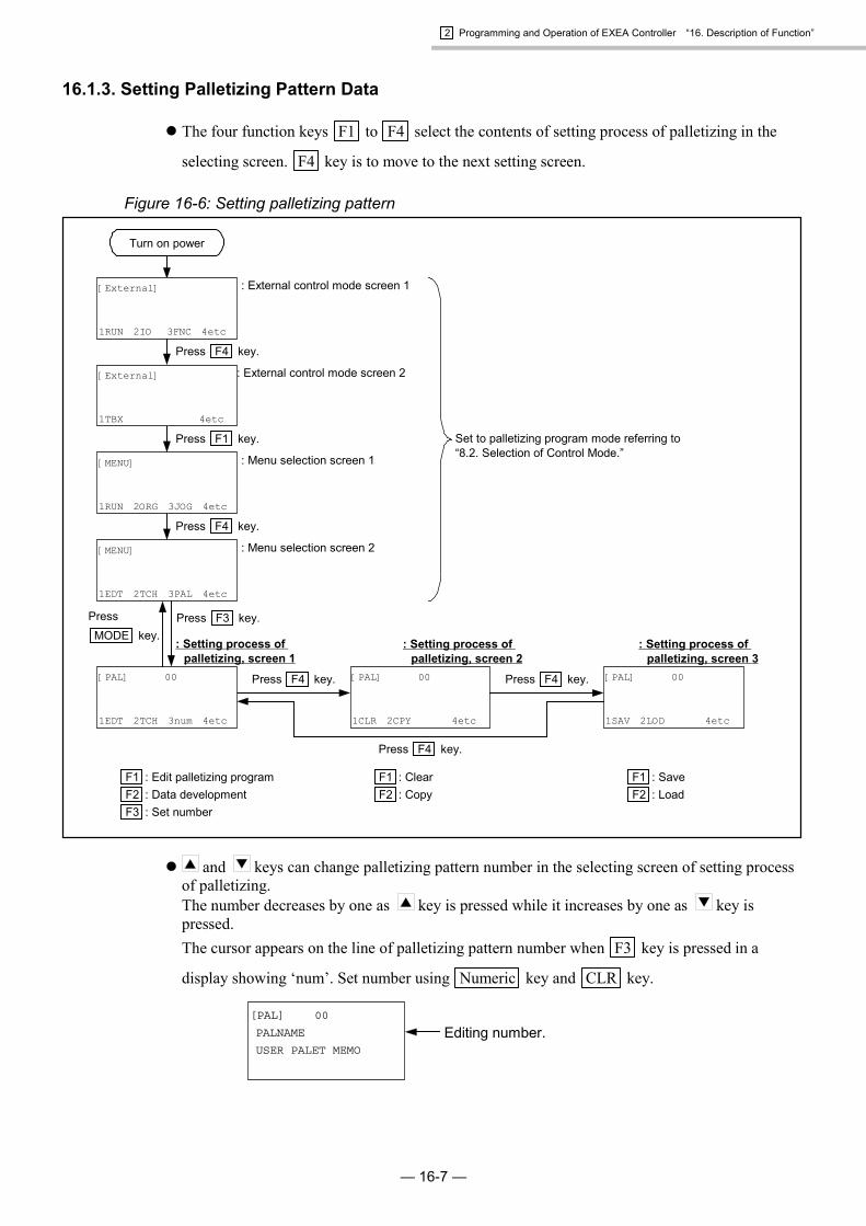
2 Programming and Operation of EXEA Controller “16. Description of Function”
— 16-7 —
16.1.3. Setting Palletizing Pattern Data
� The four function keys F1 to F4 select the contents of setting process of palletizing in the
selecting screen. F4 key is to move to the next setting screen.
Figure 16-6: Setting palletizing pattern
: Setting process ofpalletizing, screen 1
Press F4 key.
: External control mode screen 1
: External control mode screen 2
Press F1 key.
: Menu selection screen 1
Press F4 key.
: Menu selection screen 2
Press F3 key.
Set to palletizing program mode referring to“8.2. Selection of Control Mode.”
Press F4 key. [PAL] 00
1SAV 2LOD 4etc
[PAL] 00
1CLR 2CPY 4etc
[PAL] 00
1EDT 2TCH 3num 4etc
[MENU]
1EDT 2TCH 3PAL 4etc
[MENU]
1RUN 2ORG 3JOG 4etc
[External]
1TBX 4etc
[External]
1RUN 2IO 3FNC 4etc
PressMODE key.
Press F4 key.
Press F4 key.
Turn on power
: Setting process ofpalletizing, screen 2
: Setting process ofpalletizing, screen 3
F1 : Edit palletizing programF2 : Data developmentF3 : Set number
F1 : ClearF2 : Copy
F1 : SaveF2 : Load
� and keys can change palletizing pattern number in the selecting screen of setting processof palletizing.The number decreases by one as key is pressed while it increases by one as key ispressed.The cursor appears on the line of palletizing pattern number when F3 key is pressed in a
display showing ‘num’. Set number using Numeric key and CLR key.
[PAL] 00
PALNAME
USER PALET MEMO
Editing number.

2 Programming and Operation of EXEA Controller “16. Description of Function”
— 16-8 —
16.1.4. Editing Palletizing Pattern Data
� Pallet pattern data can be edited in the screens shown in Figure 16-7 that appears when F1 keysis pressed in the selecting screen of setting procedure of palletizing. Use and keys toselect the editing contents. (Screen scrolls in the order as shown in the figure.) The screendisplays a letter E on the right side of [PAL] while editing.
Figure 16-7: Editing data of palletizing pattern
Editing data.
: Edit name.
: Edit memo.
: Select palletizingposition pattern
: Set moving unit.
: Set start position.
: Set positioningintervals.
: Set data developmentformat.
: Set jump format.
: Set operation pattern
: Set number ofintervals.
: Set corner point Y.
: Set corner point X.
Press F1 key.
[PAL]E 00 NOP
P register
[PAL]E 00 XNRM
Move pattern
[PAL]E 00 NOP
Point junp
[PAL]E 00X000 Y000
Size
[PAL]E 00X±0000.00 Y±0000.00
Y position
[PAL]E 00X±0000.00 Y±0000.00
X posotion
[PAL]E 00USER PALET MEMO
Memo
[PAL] 00
1EDT 2TCH 3num 4etc
[PAL]E 00PALNAME Name
[PAL]E 00X±0000.00 Y±0000.00
Width
[PAL]E 00X±0000.00 Y±0000.00
Start position
[PAL]E 00X X Y Z
Axis
[PAL]E 00MLT
Type
Press key.
Press key.
Press key.
Press key.
Press key. Press key.
Press key. Press key.
Press key. Press key.
Press key.
PressMODE
key.
� The cursor, which appears in the screen when is pressed after the editing objective isdisplayed, enables to change editing contents. Pressing SET key makes the set contents
effective while pressing MODE key interrupts setting.

2 Programming and Operation of EXEA Controller “16. Description of Function”
— 16-9 —
16.1.4.1. Naming Palletizing Pattern
� The screen shown below appears for naming of palletizing pattern. SET key is to enter
character strings and MODE key is to interrupts entering.
[PAL]E 00
PALNAME
Name
� Move the cursor by and keys and select characters by and key. and keyschange the characters indicated by the cursor in the order as shown below.
key -------A � 9 � 8 ~ 0 � 1 � Z � Y � X---------- B � A � 9 � 8 ~
key -------A � B � C ~ X � Y � Z � 0 � 1--------- 8 � 9 � A � B ~
* Letter A is set when and is pressed in a blank.
� CLR key is to clear a character indicated by the cursor. +/- key is to insert a selected letter onthe cursor position. The number of letters for naming is limited to 8.
* Name of palletizing pattern is not set in the initializing state. You may use the nameinstead of palletizing pattern number in PALI command. Naming does not do anythingto execute a programmed palletizing operation.
16.1.4.2. Writing Memo
� The screen shown below appears for putting memo on a program. SET key is to enter a
character string and MODE key is to interrupts entering.
[PAL]E 00
PALMEMO
Memo
� Move the cursor by and keys and select characters by and keys. and keyschange the characters indicated by the cursor in the order as shown below.
key -------A � 9 � 8 ~ 0 � 1 � Z � Y � X---------- B � A � 9 � 8 ~
key -------A � B � C ~ X � Y � Z � 0 � 1--------- 8 � 9 � A � B ~
* Letter A is set when and is pressed in a blank.
� CLR key is to clear a character indicated by the cursor. +/- key is to inset a selected letter onthe cursor position. The number of letters for memorandum is limited to 16.
* Memo to a program is not set in the initializing state. Memo does not do anything to apalletizing operation. Use it as a your note.

2 Programming and Operation of EXEA Controller “16. Description of Function”
— 16-10 —
16.1.4.3. Format of Palletizing Position Setting
� The screen shown below appears for selecting a palletizing pattern. Press key to indicate thecursor, then select a pattern by and keys. SET key is to enter the selection and MODEkey to interrupt entering.
[PAL]E 00
MLT
Type
� Scroll and set the screen using and keys for palletizing position.
MLT DIV PNT MLT
� Palletizing position setting formats and their codes are shown below.MLT ----- Multiple reqular intervalDIV ------ Divided sidesPNT------ Three corners
Figure 16-8: Position setting format
MLT pattern
m places
n placesX axis interval
Y ax
is m d
ivis
ions
Corner point XStart position
Corner point YPNT patternDIV pattern
X axis size, n divisions
Y ax
is s
ize,
m d
ivis
ions
n divisions
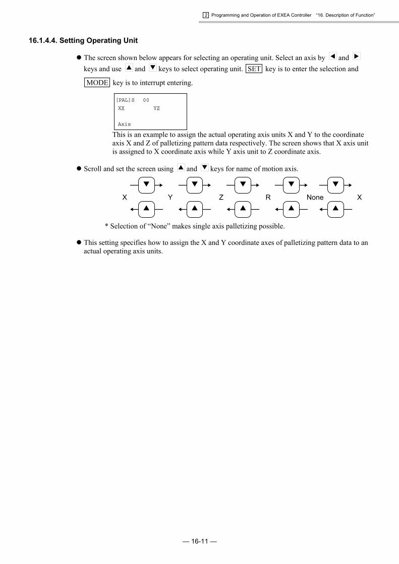
2 Programming and Operation of EXEA Controller “16. Description of Function”
— 16-11 —
16.1.4.4. Setting Operating Unit
� The screen shown below appears for selecting an operating unit. Select an axis by and keys and use and keys to select operating unit. SET key is to enter the selection and
MODE key is to interrupt entering.
[PAL]S 00
XX YZ
Axis
This is an example to assign the actual operating axis units X and Y to the coordinateaxis X and Z of palletizing pattern data respectively. The screen shows that X axis unitis assigned to X coordinate axis while Y axis unit to Z coordinate axis.
� Scroll and set the screen using and keys for name of motion axis.
X Y Z
▼
▲
▼
▲
▼
▲
R
▼
▲
None
▼
▲
X
* Selection of “None” makes single axis palletizing possible.
� This setting specifies how to assign the X and Y coordinate axes of palletizing pattern data to anactual operating axis units.

2 Programming and Operation of EXEA Controller “16. Description of Function”
— 16-12 —
16.1.4.5. Setting Start Position
� For selecting the start position of palletizing, use a screen to set a point number or direct positiondata as shown below. Press key to indicate the cursor, then select and keys to switchthe screen of register number or direct data.
� The screen shown below appears for setting a point number. Set a number of the start point ofpalletizing operation by Numeric keys. SET key is to enter the setting and MODE key is tocancel it.
[PAL]E 00
P0000
Start Position
� Point number
� The screen shown below appears to set a position data directly. Select an axis by and keys and set coordinate data of the start position of palletizing using numeric keys. SET key is
to enter the setting and MODE key is to cancel it.
[PAL]E 00
X±0000.00 Y±0000.00
Start Position
� In the absolute coordinate format, the coordinate data set in this process is specified as the startposition of palletizing operation. In case of the relative coordinate format, the current position isspecified as the start point, and from this point a palletizing operation starts following the palletposition number.(In case of the relative coordinate format, the start position set in this process is used only formaking the palletizing pattern data.)
� When start position is specified by a point number, the data for a unit other than specifiedoperation axis unit does not have the meaning. If the position data of operating axis unit is notset (when data is ××××.××), the palletizing operation is impossible to perform.
Figure 16-9: Start position of palletizing
Start position
Origin
Pallet

2 Programming and Operation of EXEA Controller “16. Description of Function”
— 16-13 —
16.1.4.6. Setting Position Interval
� Use a screen to set point number, or a screen to set position interval directly as shown below forsetting position interval. Press key to indicate the cursor, then use and keys to switchthe screen of number or interval data.
� In case of setting point number, the screen displays as shown below. Use Numeric keys to
select a point number that represents interval data. SET key is to enter the data and MODEkey is to cancel it.
[PAL]E 00
P0000
Width
� Point number
� In case of direct setting of position interval data, the screen displays as shown below. Press and keys to set an axis unit and Numeric keys to set interval data. SET key is to enter the
data and MODE key is to cancel it.
[PAL]E 00
X±0000.00 Y±0000.00
Width
� When specify the position interval by a point number, the data for a unit not specified as an axisunit does not have any meaning. If the position data of an axis unit is not set (when data is××××.××), the palletizing operation is impossible to perform. The interval data is valid for DIV(Divided position setting) and MLT (Multiple position interval) format only.
Figure 16-10: Position interval data
Interval data (Multiple regular interval)
Interval data (Divided position setting)

2 Programming and Operation of EXEA Controller “16. Description of Function”
— 16-14 —
16.1.4.7. Setting Position of Corner Point X
� For setting position of corner point X, use a screen to set point number or a screen for directposition data setting as shown hereunder. Press key to indicate the cursor, then use and
keys to switch the screen of point number or position data.
� In case of using point number, the screen displays as shown below. Use Numeric keys to select
a point number that indicates the position of corner point X. SET key is to enter the data and
MODE key is to cancel the data.
[PAL]E 00
P0000
X Position
� Point number
� In case of direct setting of position data, the screen displays as shown below. Press and keys to set a operating unit and Numeric keys to set the position data. SET key is to enter the
data and MODE key is to cancel the data.
[PAL]E 00
X±0000.00 Y±0000.00
X Position
� When specify the start position by a point number, the data for a unit not specified as an axis unitdoes not have any meaning. If the position data of an axis unit is not set (when data is ××××.××),it is impossible to perform the palletizing operation. Setting of position of corner point is validfor PNT (three point setting) pattern only.
Figure 16-11: Position of Corner Point X
Start position
Origin
Pallet
Corner point X

2 Programming and Operation of EXEA Controller “16. Description of Function”
— 16-15 —
16.1.4.8. Setting Position of Corner Point Y
� For setting of position of corner point Y, use a screen to set point number or a screen for directposition data setting as shown below. Press key to indicate the cursor, then use and keys to switch the screen of register number or position data.
� In case of using point number, the screen displays as shown below. Use Numeric keys to select
a point number that indicates the position of corner point Y. SET key is to enter the data and
MODE key is to cancel the data.
[PAL]E 00
P0000
Y Position
� Point number
� In case of direct setting of position data, the screen displays as shown below. Press and keys to set a operating unit and Numeric keys to set the position data. SET key is to enter the
data and MODE key is to cancel the data.
[PAL]E 00
X±0000.00 Y±0000.00
Y Position
� When specifying the start position by a point number, the data for a unit not specified as an axisunit does not have any meaning. If the position data of an axis unit is not set (when data is××××.××), it is impossible to perform the palletizing operation. Setting position of corner pointY is valid for PNT (three point setting) pattern only.
Figure 16-12: Position of corner point Y
Start position
Origin
Pallet
Corner point Y

2 Programming and Operation of EXEA Controller “16. Description of Function”
— 16-16 —
16.1.4.9. Setting Number of Position Intervals
� For setting number of position intervals, use a screen to set point number or a screen for directsetting of position interval as shown hereunder. Press key to indicate the cursor, then use and keys to switch screen of register number or position data.
� In case of setting point number, the screen displays as shown below. Use Numeric keys to set a
point number that indicates pallet size. SET key is to enter the data and MODE key is tocancel the data.
[PAL]E 00
P0000
Size
� Point number
� In case of direct setting of position interval data, the screen displays as shown below. Press and keys to set a operating unit and Numeric keys to set number of position interval data.
SET key is to enter the data and MODE key is to cancel the data.
[PAL]E 00
X000 Y000
Size
� When specifying the number of position intervals by a point number, the data for a unit notspecified as an axis unit does not have any meaning. If the position data of an axis unit is not set(when data is ××××.××), it is impossible to perform the palletizing operation. The data is anumber of divisions in DIV format (Divided sides format) and PNT format (three cornersformat), while the data for MLT format (Multiple regular interval) is a multiple value.
Figure 16-13: Position setting format
MLT format
m places
n placesX axis interval
Y ax
is m d
ivis
ions
Corner point XStart position
Corner point YPNT formatDIV format
X axis size, n divisions
Y ax
is s
ize,
m d
ivis
ions
n divisions

2 Programming and Operation of EXEA Controller “16. Description of Function”
— 16-17 —
16.1.4.10. Setting Moving Order
� The screen shown below appears to set moving orders. Press key to indicate the cursor, thenuse and keys to set moving orders. SET key is to enter the data and MODE key is tocancel the data.
[PAL]S 00
XNRM
Move pattern
� Scroll screens by and keys. The order of screens is shown below.
XNRM XREV YNRM XNRMYREV
� Code list of moving order.XNRM ------ X axis unit takes precedence. Moves to one direction.XREV ------- X axis unit takes precedence. Moves in both direction.YNRM ------ Y axis unit takes precedence. Moves to one direction.YREV ------- Y axis unit takes precedence. Moves in both direction.
Figure 16-14: Moving direction
Y co
ordi
nate
X coordinate
X axis unit takes precedence.Moves to one direction.
XNRM
X axis unit takes precedence.Moves in both direction.
XREV
Y axis unit takes precedence.Moves to one direction.
YNRM
Y axis unit takes precedence.Moves in both direction.
YREV

2 Programming and Operation of EXEA Controller “16. Description of Function”
— 16-18 —
16.1.4.11. Selection of Jump Format
� The screen shown below appears to set jump format. Press key to indicate the cursor, thenselect jump format using and keys. SET key is to enter the data and MODE key is tocancel the data.
[PAL]E 00
NOP
Point Jump
� Scroll screens by and keys. The order of screens is shown below.
NOP SPS JMP NOP
� Code list of Jump format:NOP ----- No jumpSPS ------ Jump (Positioning to start position)JMP------ Jump (No positioning to start position)
Figure 16-15: Jump format
NOP SPS JMP
: Start position of palletizing
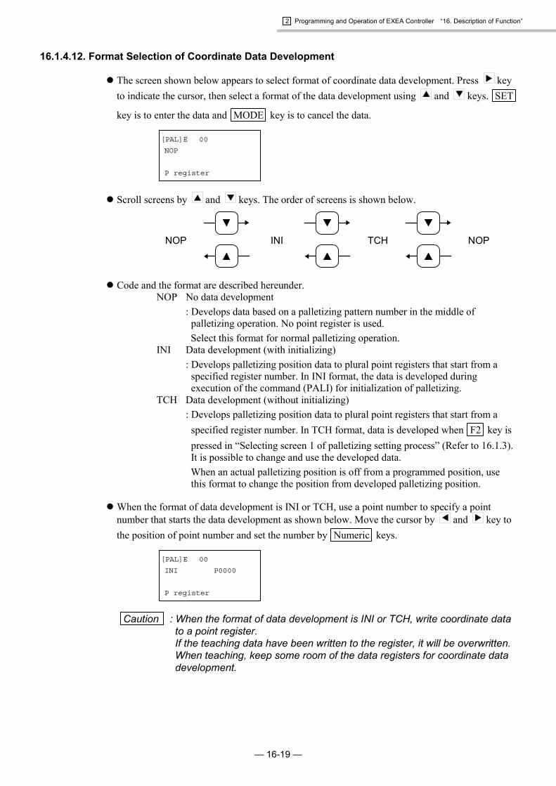
2 Programming and Operation of EXEA Controller “16. Description of Function”
— 16-19 —
16.1.4.12. Format Selection of Coordinate Data Development
� The screen shown below appears to select format of coordinate data development. Press keyto indicate the cursor, then select a format of the data development using and keys. SET
key is to enter the data and MODE key is to cancel the data.
[PAL]E 00
NOP
P register
� Scroll screens by and keys. The order of screens is shown below.
NOP INI TCH NOP
� Code and the format are described hereunder.NOP No data development
: Develops data based on a palletizing pattern number in the middle ofpalletizing operation. No point register is used.
Select this format for normal palletizing operation.INI Data development (with initializing)
: Develops palletizing position data to plural point registers that start from aspecified register number. In INI format, the data is developed duringexecution of the command (PALI) for initialization of palletizing.
TCH Data development (without initializing): Develops palletizing position data to plural point registers that start from a
specified register number. In TCH format, data is developed when F2 key ispressed in “Selecting screen 1 of palletizing setting process” (Refer to 16.1.3).It is possible to change and use the developed data.
When an actual palletizing position is off from a programmed position, usethis format to change the position from developed palletizing position.
� When the format of data development is INI or TCH, use a point number to specify a pointnumber that starts the data development as shown below. Move the cursor by and key tothe position of point number and set the number by Numeric keys.
[PAL]E 00
INI P0000
P register
Caution : When the format of data development is INI or TCH, write coordinate datato a point register.If the teaching data have been written to the register, it will be overwritten.When teaching, keep some room of the data registers for coordinate datadevelopment.

2 Programming and Operation of EXEA Controller “16. Description of Function”
— 16-20 —
16.1.5. Development of Palletizing Data
� When TCH format is set in the format selecting screen of developing coordinate data (refer to“16.1.4.12. Format Selection of Coordinate Data Development.”) in setting process of palletizingoperation, pressing F2 in “Selecting screen 1 of palletizing setting process” (refer to “16.1.3.Setting Palletizing Pattern.”) gives the screen below and enables to set the range of palletizingpattern on which the data development is performed. Pressing SET key starts the development.
[PAL] 00
1EDT 2TCH 3num 4etc
[PAL] 00
PALNAME
USER PALET MEMO
TCH(00>00)?
Starting palletizingpattern number
Ending palletizingpattern number
Press F2 key.
: Selecting screen 1 of palletizing setting process
� The developing range shall be set from the starting (a palletizing pattern number currentlydisplayed) to the ending. (The same number of the starting is displayed for ending number. Youcan enter a desired number here.)You can change the range by Numeric key or and keys. Set directly a number of cursorposition using Numeric key or set using and keys which gives increase/decrease ofnumber by one for every pressing.
* If a larger ending number than the existing palletizing pattern number is specified, thedata development ends at the largest number of existing setting.
� The cursor moves directly to the starting number when F1 key is pressed, while it moves to the
ending number when F2 key is pressed. Pressing • key sets all palletizing pattern number asthe range and the screen appears as shown below. To terminate this state and back to numericsetting, press Numeric keys.
[PAL] 00
PALNAME
USER PALET MEMO
TCH(00>00)?
[PAL] 00
PALNAME
USER PALET MEMO
TCH(ALL )?
Press • key.
Caution : When TCH format is set for coordinate data development, store the pointregister data after the developments. Otherwise they will be lost as thepower is turned off. Be sure to store the data as well as the teaching databefore the power is turned off. Refer to “15.1.4. Saving Point Data.”

2 Programming and Operation of EXEA Controller “16. Description of Function”
— 16-21 —
16.1.6. Clear Palletizing Data
� When you press F1 key (CLR) in the setting screen 2 of process of palletizing setting, thescreen shown below appears and you can clear a palletizing pattern data. (refer to “SettingPalletizing Pattern Data.”) On the last line, specify a palletizing pattern number, then press SETkey for deleting its data. (change to none-data state.)
[PAL] 000
1CLR 2CPY 4etc
[PAL] 000
CLR(00>00)?
Ending palletizingpattern number
Press F1 key.
: Selecting screen 2, palletizing setting process
Starting palletizingpattern number
� The range to be cleared shall be set from the starting (a palletizing pattern number currentlydisplayed) to the ending. (The same number of the starting is displayed for ending number. Youcan enter a desired number here.)You can change the range by Numeric key or and keys. Set directly a number of cursor
position using Numeric key or set using and keys which gives increase/decrease innumber by one at every pressing.
* If a larger ending number than the existing palletizing pattern number is specified, thelargest number is regarded as the end number and the data is processed accordingly.
� The cursor moves directly to the starting number when F1 key is pressed, while it moves to the
ending number when F2 key is pressed. Pressing • key sets all palletizing pattern number andthe screen appears as shown below. To terminate this state and back to numeric setting, pressNumeric keys.
[PAL] 000
CLR(00>00)?
[PAL] 000
CLR(ALL )?
Press • key.

2 Programming and Operation of EXEA Controller “16. Description of Function”
— 16-22 —
16.1.7. Copy Palletizing Data
� When you press F2 key in the selecting screen 2 of process of palletizing setting (“SettingPalletizing Pattern Data.”), the screen shown below appears and you can copy a palletizingpattern data. On the last line, specify a palletizing pattern number, then press SET key forcopying its data.
Press F2 key.
[PAL] 000
CPY(00>00/00)?
[PAL] 000
1CLR 2CPY 4etc
Ending palletizingpattern number
Palletizing patternnumber to copy
Starting palletizingpattern number
: Selecting screen 2, palletizing setting process
� The range to be copied shall be set from the starting (a palletizing pattern number currentlydisplayed) to the ending. Set a number as the top palletizing pattern number of the range tocopy. Move between ‘the ending number to be copied’ and ‘the starting number to copy’ using
and .You can set each number by Numeric key or and keys. Set directly a number of cursor
position using Numeric key or set a number using and keys which givesincrease/decrease in number by one at every pressing.
* The same number is on the ending palletizing pattern number and starting thepalletizing pattern number to copy. Set a desired number to start copy.
* If a larger ending number than the existing palletizing pattern number is specified, thedata development ends at the largest number of existing setting.
* When the copy range is less than the copied range, the over flown data will be lost.
* When the copy and copied range overlap each other, the previously written data willremain in the area.

2 Programming and Operation of EXEA Controller “16. Description of Function”
— 16-23 —
16.1.8. Saving Palletizing Data
� Pressing F1 key in the selecting screen 3 of the process of palletizing setting, you can save theediting result to the flash memory. (Refer to “16.1.3. Setting Palletizing Pattern Data.”)
� Pressing F2 key in the selecting screen 3 as same as above, you can read out the data in theflash memory.
� Turning off the power before saving the results of editing, you will lose them. The followingscreens appears during writing to the flash memory.
Press F1 key.
[PAL]
Writing
[PAL] 000
1SAV 2LOD 4etc
: Selecting screen 3, palletizing setting process
Caution : Do not turn off the power while “Writing” is on the display. Otherwisememory error alarm will be given.

2 Programming and Operation of EXEA Controller “16. Description of Function”
— 16-24 —
16.2. Arch Motion (Malti-axis combination only)
� When a linear motion cannot be performed because an obstacle blocks the motion trajectory, youcan program an arch motion by setting an off-limits area. The off-limits area is set by the upperoff-limits and lower off-limits boundaries.
� The robot moves to Z axis coordinate direction from the start point, then moves to X axiscoordinate direction along the turnout coordinate after it clears upper (or lower) off-limitsboundary and moves back in Z axis coordinate direction to the destination.(Refer to Figure 16-16.)
Figure 16-16: Outline of arch motion
X coordinate axis
Z coordinate axis
Start position End position
Turnout positionUpper off-limits boundary
Lower off-limits boundary
When turnout position is on upper off-limits boundary side:
X coordinate axis
Z coordinate axis
Start position End position
Upper off-limits boundary
Lower off-limits boundary
When turnout position is on lower off-limits boundary side:
Turnout position
Caution : If the setting of turnout position is not selected to the motion format orthe off-limits boundary and turnout position of Z axis coordinate is notset in the initialization, the robot moves linearly.
Note: (1) Add an allowance of 10 mm approximately to the setting of off-limits boundary (upper /lower) and confirm that there is no interference with the objects in the off-limits area.
(2) When the upper off-limits boundary and the turnout position are too much apart from eachother, or acceleration is set too low, the trajectories of starting and ending of arch motionmay not be the same.
� The arch motion starts by “MOV” command. Arch motion becomes active if the motion formatE (sets turnout.) is specified.
� The arch motion is valid only when Z axis off-limits boundaries and a turnout position isinitialized.The off-limits area and turnout position of R axis do not function.
* Refer to “9.3.4. Parameters for Coordinates and Position.”
� Set the units to X and Z axis units in case of 2 axes control, while YZ or XYZ for 3 or 4 axescontroller.
* Refer to “9.5. Parameters for Unit setting” for more details.
� Refer to “15.3.6. Arch Motion in Two Axes Motion.”

2 Programming and Operation of EXEA Controller “16. Description of Function”
— 16-25 —
16.2.1. Initial Setting
� Set the off-limits boundary and the turnout position referring to “9.3.4. Parameters for Positionand Coordinates.”
Table 16-2: Off-limits / turnout parameterParameter Description Unit Setting range Factory set
Escape (upr.Z)� Set the upper off-limits boundary.� Setting of motion range of the arch motion
using Z axis unit.mm -9999.99 ~ 9999.99 0
Escape (lwr.Z)� Set the lower off-limits boundary.� Setting of motion range of the arch motion
using Z axis unit.mm -9999.99 ~ 9999.99 0
Escape (pos.Z)� Set turnout position of Z axis.� Setting of motion range of the arch motion
using Z axis unit.mm -9999.99 ~ 9999.99,
OFF OFF
Escape (upr.R) � Reserved – – –Escape (lwr.R) � Reserved – – –Escape (pos.R) � Reserved – – –
� The motion to move to the turnout position starts when the start or end position is between theupper and lower off-limits boundary.
� When the start and end positions are out of the boundary, the motion is linear, not arch motion,to the end position.
Figure 16-17: Start position and off-limits boundaries
X coordinate axis
Z coordinate axis
Start positionEnd position
Turnout positionUpper off-limits boundary
Lower off-limits boundary
When start position is between off-limits boundaries (Execute arch motion):
X coordinate axis
Z coordinate axis
Start position End position
Upper off-limits boundary
Lower off-limits boundary
When start and end positions are out of the off-limits boundaries(Does not execute arch motion) :
Turnout position

2 Programming and Operation of EXEA Controller “16. Description of Function”
— 16-26 —
16.2.2. Programming
� Program an arch motion referring to “15. Programming.”
� Set ESCZ command to change off-limits boundary and turnout position in the middle of anoperation.
Note : ESCZ is a command to change the off-limits boundary and the turnout position. It is notvalid unless an arch motion is set initially (&E).
� Command to specify the arch motion is one of the motion format to MOV command. Set theturnout position (&, E) of a motion format active.
Figure 16-18: Example of program
120.0100.0
Program Description<Start: Move to start position.>
MOV X0050.00 Z0010.00S0100.0 A0.5 B0.5
Move to start position (50.0, 10.0) from current position. (can be anywhere)(Resultant speed: 100 mm / s, Acceleration/ deceleration: 0.5 m / s2, Absolute coordinateformat)<Set parameter for interpolation>
SPD S0600.0 A3.0 B3.0 Set motion speed and acceleration/deceleration for interpolation hereunder.(Resultant speed: 600 mm / s, acceleration / deceleration: 3.0 m / s2)<Set parameters for arch motion.>
ESCZ #0000.00 #0100.00#0120.00
Lower off-limits boundary: 0.0 mm. Upper off-limits boundary: 100 mm,Turnout position: 120.00 mm
<Arch motion start>MOV X0200.00 Z30.0 &E Start arch motion to a position of absolute coordinates (200.0, 30.0)
<End of program>END CSTP
X coordinate axis
Z coordinate axis
Start position (X50.0, Z10.0) End position (X200.0, Z30.0)
Turnout positionUpper off-limits boundary
Lower off-limits boundary
Arch motion

2 Programming and Operation of EXEA Controller “16. Description of Function”
— 16-27 —
16.3. Continuous Path (Malti-axis combination only)
� Continuous path is a motion in constant speed without changing speed, acceleration anddeceleration at the passing points. This is to be used for an operation that need constant speedsuch as sealing or deburring.It is possible to change motion speed and to give an output command to the general output portin the middle of a continuous path operation.
� This motion is performed in two dimensions by 2 axes controller and in three dimensions bythree or four axes controller.
� There are some restrictions in a Continuous path program. Be sure to program correctly referringto “16.3.2. Restrictions on Program of Continuous Path.”
Figure 16-19: Continuous path
Continuous pathpositioning operation
P004
time
P003P002P001P000
P004P003P002
Normal positioningoperation
speed
FIN output
P001P000
P004P003P002P001P000
speed
FIN output
16.3.1. Command for Continuous Path
� There are two commands.CPS: Start continuous path.CPE: End of continuous path.
� Execute a motion command between CPS and CPE under constant speed.
� Commands that can be set between CPS and CPE are shown in Table 16-3.
Table 16-3: Commands that can be set between CPS and CPECommand Description
MOV Linear interpolationMOVM Continuous linear interpolationCIR Circular interpolationARC Circular arc motion commandOUT General output commandSPD Setting command of speed, acceleration and deceleration.
� See “15.3.5. Continuous Path Two Axes Motion.”

2 Programming and Operation of EXEA Controller “16. Description of Function”
— 16-28 —
16.3.2. Restrictions on Program of Continuous Path
16.3.2.1. Change Direction of Linear Motion
� When changing direction of linear motion, connect two linear trajectories with an arc and makeit smooth as possible. The actual motion trajectories are not accurate under limited power ofmotor as the speeds of each axis unit will be discontinuous at the inflection points. When themotion speeds differ greatly, an excessive current command to the motor might be given, andconsequently, an excessive current alarm arises.
� Size of radius to connect two linear motions:Please find out the size of radius from allowable acceleration and deceleration referring to Figure16-20.See “19.1.3. Precautions against Use of Module Main Unit” for allowable acceleration /deceleration of module main unit.
Figure 16-20: Restrictions on program of continuous path: In case of changing direction of linearmotion
P000
P009
P002P001
P003
P004
P006 CP005
P007
P008
••••MOV P000CPSMOV P001OUT OP10 = ;00000001MOV P002ARC P002 P003 P004MOV P005MOV P006ARC P006 P007 P008MOV P001OUT OP10 = ;00000000MOV P009CPE••••
Note: Connect two linear lines with an arc at point C. See Figure 16-21 for size of radius.

2 Programming and Operation of EXEA Controller “16. Description of Function”
— 16-29 —
Figure 16-21: Size of radius
16.3.2.2. Number of Steps between CPS and CPE Commands
� Number of steps that can be set between CPS and CPE commands are up to 100. If 101 or moresteps are set between them, a program error alarm arises.
� Be aware that the number of steps depends on a program command.
1) Normally steps for MOV, ARC, and CIR is one. However if motion speed is set, itincreases two more steps.
[Example] MOV P0000 S300: Number of steps: 3
2) For MOVM command, number of steps number of continuous points.[Example] MOVM P0001 P0050 : Number of Steps: 50
16.3.2.3. Others
� Operating time (calculation): Before starting a continue path operation, it is required to calculatetotal motion distance. If there is a lot of steps, it looks as if the robot is pausing momentarily.
� The timing to output a command during a continue path motion is delayed to the time when therobot is passing the previous point. Delay of time differs ways of programming. The delayedtime is longer for a multitask operation.

2 Programming and Operation of EXEA Controller “16. Description of Function”
— 16-30 —
16.4. Multitask
� It is possible to execute several programs simultaneously in a multitask operation, such ascontrolling input/output or controlling sequence while operating a module main unit.
� Multitask operation can be performed by a main program as a trunk and sub programs asbranches and leaves. However, you may conduct a simple multitask operation by setting aparallel operation as a motion format of MOV command. (See “15.3.8. Multitask” for programexamples.)
� You may perform a multitask operation by specifying it through a program command.
� It is required to operate a multitask when operate the several units, that are separated intoindividual units at initial setting, simultaneously and independently. It is possible to operateindividual axis units without separating from the unit as well.
� Multi-axis EXEA controller can handle up to 16 programs in the multitask operation, while asingle axis EXEA controller can handle 4 programs.
Figure 16-22: Outline of multitask
EXEA controller
Operate each module main unit independently.
Example: Unit 1, X axis Example: Unit 2, Y axis
Parallel processing ofsequential operation
Parallel processing ofinput / output
* Operation of multiple units is onlyavailable for a multi-axis combination.
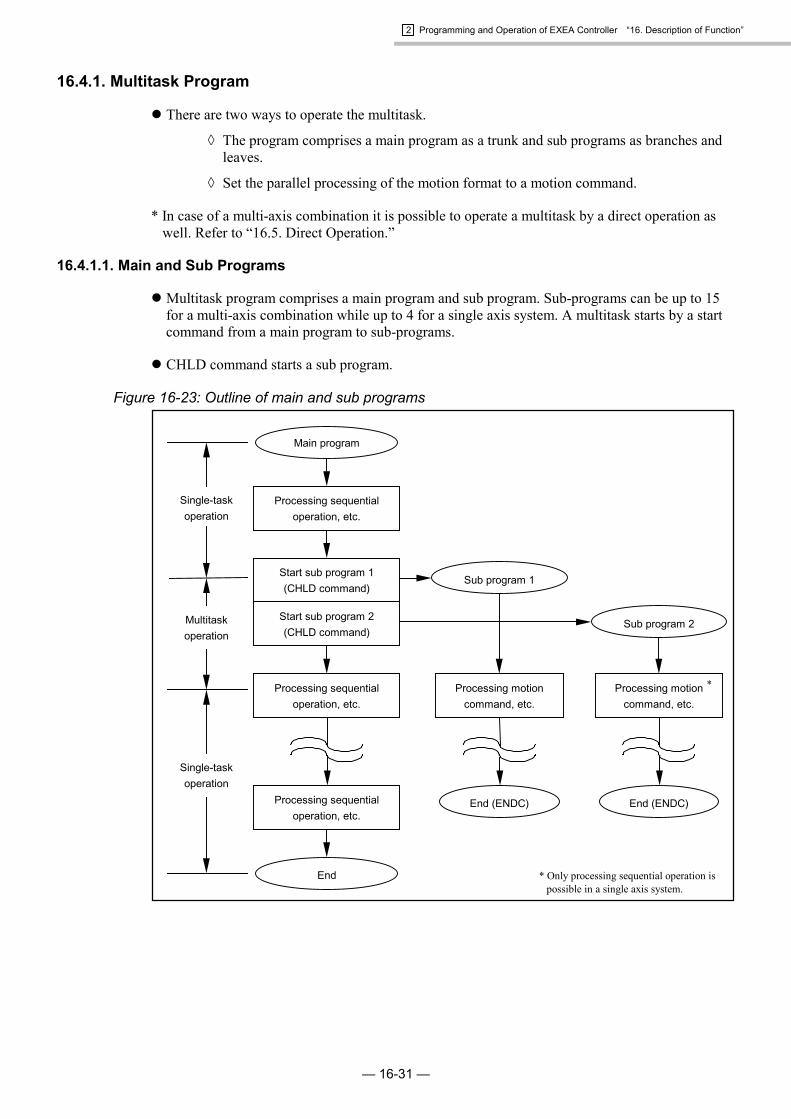
2 Programming and Operation of EXEA Controller “16. Description of Function”
— 16-31 —
16.4.1. Multitask Program
� There are two ways to operate the multitask.
� The program comprises a main program as a trunk and sub programs as branches andleaves.
� Set the parallel processing of the motion format to a motion command.
* In case of a multi-axis combination it is possible to operate a multitask by a direct operation aswell. Refer to “16.5. Direct Operation.”
16.4.1.1. Main and Sub Programs
� Multitask program comprises a main program and sub program. Sub-programs can be up to 15for a multi-axis combination while up to 4 for a single axis system. A multitask starts by a startcommand from a main program to sub-programs.
� CHLD command starts a sub program.
Figure 16-23: Outline of main and sub programs
Main program
Sub program 1
Sub program 2
Single-taskoperation
Multitaskoperation
Single-taskoperation
Processing sequentialoperation, etc.
Start sub program 1(CHLD command)
Start sub program 2(CHLD command)
Processing sequentialoperation, etc.
Processing motioncommand, etc.
Processing motioncommand, etc.
Processing sequentialoperation, etc.
End (ENDC)
End
End (ENDC)
* Only processing sequential operation ispossible in a single axis system.
*

2 Programming and Operation of EXEA Controller “16. Description of Function”
— 16-32 —
16.4.1.2. Parallel Processing
� It is possible to select parallel or normal processing as motion format of the motion commandsuch as MOV. Selecting the parallel processing as motion format enables to operate a simplemultitask in one program.
Normal processing(Motion format code W)
: Program waits to execute next step for a completion of currentmotion command.
Parallel processing(Motion format code P)
: As soon as the motion command starts, the next step of theprogram starts. However, the system has to wait tillcompletion of current motion to start a motion unit.
Figure 16-24: Outline of parallel processing
Program
Motion command(Normal processing)
Wait for completeof motion.
Normal processing format
No
Yes
End
In motion Complete motion
General input
General output
A
AUnchanged
Any data
End of program
Parallel processing format
In motion Motion complete
General input
General output An
Program start
Any data
End of program
Program start
A1 A2 A3 A4 • • •• • •
Program
Motion command(Parallel processing)
Output general input signal togeneral output port.
Wait for completeof motion.
No
Yes
End
Output a general input signalto general output port.
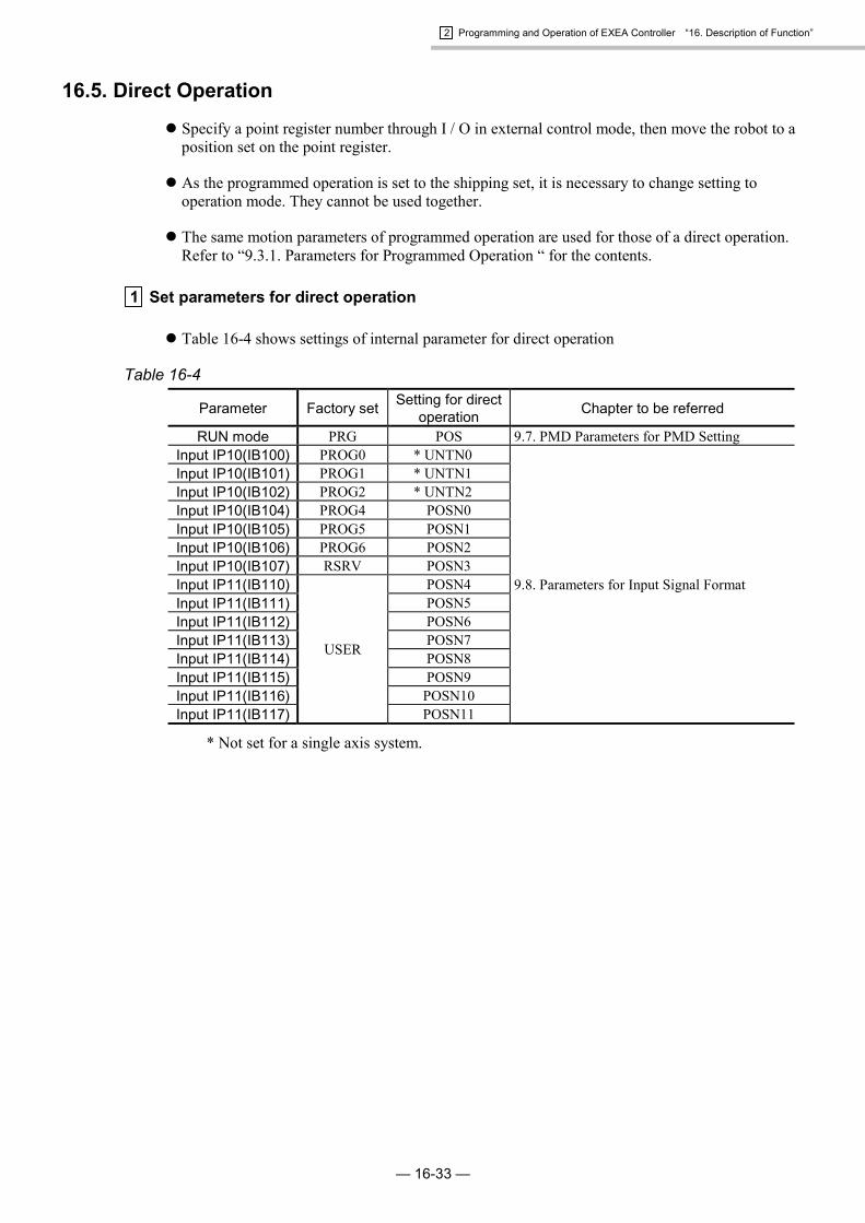
2 Programming and Operation of EXEA Controller “16. Description of Function”
— 16-33 —
16.5. Direct Operation
� Specify a point register number through I / O in external control mode, then move the robot to aposition set on the point register.
� As the programmed operation is set to the shipping set, it is necessary to change setting tooperation mode. They cannot be used together.
� The same motion parameters of programmed operation are used for those of a direct operation.Refer to “9.3.1. Parameters for Programmed Operation “ for the contents.
1 Set parameters for direct operation
� Table 16-4 shows settings of internal parameter for direct operation
Table 16-4
Parameter Factory set Setting for directoperation Chapter to be referred
RUN mode PRG POS 9.7. PMD Parameters for PMD SettingInput IP10(IB100) PROG0 * UNTN0Input IP10(IB101) PROG1 * UNTN1Input IP10(IB102) PROG2 * UNTN2Input IP10(IB104) PROG4 POSN0Input IP10(IB105) PROG5 POSN1Input IP10(IB106) PROG6 POSN2Input IP10(IB107) RSRV POSN3Input IP11(IB110) POSN4Input IP11(IB111) POSN5Input IP11(IB112) POSN6Input IP11(IB113) POSN7Input IP11(IB114) POSN8Input IP11(IB115) POSN9Input IP11(IB116) POSN10Input IP11(IB117)
USER
POSN11
9.8. Parameters for Input Signal Format
* Not set for a single axis system.

2 Programming and Operation of EXEA Controller “16. Description of Function”
— 16-34 —
2 Input / Output of direct operation
Table 16-5Connector Pin No.Signal
name CN3 P1-EXT.I/O
Description of function
SVON 8 – Input: Servo on On: Servo on OFF: Servo off
RUN 7 –Input: Startprogrammedoperation
Rising signal detection from off to on starts direct operation.
Set number of units (point registers) to be started simultaneously bybinary digit from input of UNTN 0 to 2.
0 : 0FF 1 : ONNumber of units to be operated.Input 1 2 3 · · · 8
UNTN2 0 0 0 1UNTN1 0 0 1 · · · 1UNTN0 0 1 0 1
UNTN0 *~
UNTN2– 10,
27, 28Input: Selectionof unit numbers.
Select point registers to be operated by binary digit from POSN0 to 11.0 : OFF 1 : ON
Point register No.Input 0 1 2 · · · 3999POSN11 0 0 0 1POSN10 0 0 0 1POSN9 0 0 0 1POSN8 0 0 0 1POSN7 0 0 0 1POSN6 0 0 0 · · · 0POSN5 0 0 0 0POSN4 0 0 0 1POSN3 0 0 0 1POSN2 0 0 0 1POSN1 0 0 1 1POSN0 0 1 0 1
POSN0~
POSN11– 3 ~ 8,
20 ~ 26
Input: Selectionof Point registernumber.
MTN 34 – Output: Inmotion
It is closed when the robot is in motion.It opens at end of motion.
HOLD 5 – Input: Hold When it is on during direct operation, the robot decelerates and stops.�Command to start direct operation is not valid while it is on.
STOP 26 – Input: Forcedstop
When it is on during direct operation, the robot decelerates and stops.�Command to start direct operation is not valid while it is on.
HOLDA 13 – Output: On hold It is closed while HOLD input is on.
* Not used for a single axis system.

2 Programming and Operation of EXEA Controller “16. Description of Function”
— 16-35 —
3 How to use UNTN signal. (Multi-axis combination only)
� UNTN signal specifies number of units (point registers) to be started simultaneously.
[Example]P0000 X0000.00 Y0000.00 U1P0001 X0010.00 Y0000.20 U2P0002 X0030.00 Y0040.00 U3
If there are teaching point data of Unit 1 ~3 in point numbers P0000 ~ P0002 as shown above,designation of a point number to 0 (zero) by POSN0 ~ 11 signals and setting the number of unitsto 3 by signals UNTN0 ~ 2 start P0000 and P0001 simultaneously and put the main units of U1and U2 module in parallel operation (multitask operation).When number of units is set to 2, P0000 and P0001 start simultaneously and U1 and U2 modulestart parallel operation (multitask operation). Error (F5: unit overlap) arises if the setting of aunit number of point register is duplicated.
4 Procedure of direct operation
1) Turn Servo on referring to “17.4.2. Servo on.”
2) Perform Home return referring to “17.4.3. Home Return.” Once the Home position is establishedyou do not need Home return in daily bases.
3) Confirm the state of following input and output.Input off: CSTP, STOP and HLDOutput: MTN opened
You cannot operate direct operation when STOP and HLD inputs are on. Direct operation cannotbe started again if MTN output is closed (in the middle of direct operation).
� Wait for end of direct operation or force to terminate direct operation by inputting STOP.(Turn off STOP input after end of direct operation.)
4) Specify a desired point number to be operate by selecting input of a point number.
5) Turn on RUN input. Direct operation starts and MTN output is closed.
Note: Refer to “17.4.5. Stopping Programmed Operation” for procedure to stop direct operation.However, CSTP input (cycle stop) is invalid in direct operation. (It is ineffective.)
6) MTN output is opened at the end of direct operation.
Note: (1) Selecting input of point number is invalid once a direct operation starts. (duringMTN output is closed.) For changing number of point register, it is necessary to waittill the end of direct operation or force to terminate a direct operation by STOP input.
(2) RUN input is detected as ON by recognition of rising current (effective at changingpoint of off to on). Direct operation cannot start when RUN is on from the beginning.
(3) It is possible to make operation in relative coordinates when (I) (relative coordinatesformat) is specified to point register setting. Otherwise absolute coordinates format isset. Refer to “15.1. Teaching.”

2 Programming and Operation of EXEA Controller “16. Description of Function”
— 16-36 —
5 Sequential timing of control input / output
� Perform a direct operation following the timing as shown in Figure 16-25.
Figure 16-25
Min. 10ms
ONOFF
Min. 10ms
Start Start
Note (2)
Note (1)Min. 10ms
Min. 10ms
SVON input
STOP input
CSTP input
Set number of units(UNTN0 ~ UNTN2)
Select point number(POSN0 ~ 11 input)
RUN input
Execute directoperation(Motion of unit 1)
(Motion of unit 2)
HOME output
MTN output
Min. 1s
Min. 10msON
OFF
ONOFF
closeopen
ONOFF
closeopen
Point 0 Point 2Point 1
Unit 1:Move to point 2
Min. 10ms Min. 10ms Min. 10ms
Unit 1:Move to point 1.
Min. 10ms Note (1)Number of unit: 1 Number of unit: 2
Unit 2:Move to point 3
Note (3)
Note: (1) Selection of point number and setting number of units are invalid until end of directoperation once it started (MTN output close).
(2) RUN input is invalid until end of direct operation once it started (MTN out putclose).
(3) It does not need for a single axis system.
* In the example shown above, the point numbers “0” to “1” are set to Unit 1, while the pointnumber “3” is set to Unit 2.

2 Programming and Operation of EXEA Controller “16. Description of Function”
— 16-37 —
6 Timing to handle stop commands in the middle of direct operation
� Be sure to observe the timing shown in Figure 16-26.
Figure 16-26
Min. 10ms
Min. 10msMin. 10msMin. 10ms
Min. 10ms
RUN input
CSTP input
STOP input
HOLD input
Executing directoperation
MTN output
HOLDA output
CSTPA output
ONOFF
ONOFF
ONOFF
closeopen
ONOFF
closeopen
closeopen
Remainpoint
No. n+1Point
No.n+5Point
No.n+2Point
No.n+1Point
No.n+4Point
No.n+3PointNo.n
Min. 10ms
Min. 10msMin. 10ms
Min. 10ms

2 Programming and Operation of EXEA Controller “16. Description of Function”
— 16-38 —
(Blank Page)

2 Programming and Operation of EXEA Controller “17. Operation of Robot Module”
— 17-1 —
17. Operation of Robot Module� This chapter describes how to operate the robot module system as well as the operational
functions that are necessary to operate the system.
Danger : Do not enter in the guard fence (provided by user) when the robot system isoperating. If you go beyond the guard fence for unavoidable reason, besure to stay out of working area of module main units and set the speed ofmodule main units to a safety speed (250 mm/ sec or less). Be careful notto be hit or crushed by the robot.
Caution : When you have prepared a new program or changed a program, werecommend to perform a trial operation to check if the system works as youhave intended. Make sure to prevent the work piece or end effectors frombeing damaged by unexpected movement of the robot module system inthe trial running. If the program does not work as intended, re-program ituntil it works properly.
17.1. Power On and Off
� Procedure for turning power on
� See “8.1. Turn on Power” before turning on your robot module for starting up or re-starting afterthe system modifications.
� In this chapter, the procedure for turning on the robot module for daily operation is presented.
1) Check the cables and connectors for:
� Loose or disconnected connectors. Deteriorated or damaged cables.
� Wrong axis connection.
2) Check main units for:
� Loose bolts.
� End effector. (provided by the user)
3) Check that no person nor devices which could be injured or damaged by the module is in theworking area of the robot.
4) If everything is satisfactory, turn on DC 24V external power supply first, when DC 24V externalsupply is used.
5) Turn on main power of EXEA controller if everything is normal.

2 Programming and Operation of EXEA Controller “17. Operation of Robot Module”
— 17-2 —
� When turn off power
1) Stop operation of the robot.
� During operation using teaching box : Press STOP key.
Note: STOP key is not valid unless programmed operation mode is set.
� During external control : Turn on STOP input signal.
� During remote control : Input STOP command.
2) Make sure that the slider of main unit (or the main unit when it is moving) stops completely,then turn the servo off.
� During the operation using teaching box : Press OFF key.
� During external control : Turn off SVON input.
� During remote control : Input SVOF command.
3) Turn the power off.
Caution : If the power is turned off in the “SVON” state, the slider (or the main unitwhen it is moving) of a vertical axis may drop for 5 to 10 mm due to the timelag of excitation of motor brake solenoid.

2 Programming and Operation of EXEA Controller “17. Operation of Robot Module”
— 17-3 —
17.2. Checking before Start Operation
� Before start operation, check the robot system.
� Determine check items centering operational safety in accordance with user’s applications.
Danger : Observe the two checking items described below. If failures of theemergency stop function is overlooked, serious danger could resultbecause the stop functions would not work in an emergency.
1) Execute jog operation referring to “17.3.2. Jog Operation.”
� This is to check if the controller and motor system work properly. If the jog operationcannot be made because your application does not require the teaching box, check thesystems by alternative way such as a programmed trial operation.
� Do the systems work smoothly as intended? If not, take necessary measures referringto “14. Troubleshooting.”
2) Check stopping functions
� Emergency stop function: Emergency stop key of teaching box: EMST input of CN3 connector: EMST command (remote control only)
� Gets into “emergency stop” state when a procedure for emergency stop is executedduring jog operation.
* For procedure for emergency stop and its state, refer to “11.3.1. Emergency Stop.”
* When the system enters emergency state, F5 alarm (program error) will arise.
� Function of dead-man switch: The switch located on the side of teaching box.
� During jog operation, the system gets in servo off state and stops operation when thedead-man switch is released.
� Before start the operation, be sure to check that the stop functions work properly.

2 Programming and Operation of EXEA Controller “17. Operation of Robot Module”
— 17-4 —
17.3. Operation by Teaching Box
� Teaching box allows you to execute Home return, jog and programmed operation.
� Procedures to perform operations using the teaching box are described hereafter.
Caution : When operating the robot module through the teaching box, all controlinputs (connector CN3), except EMST input, are invalid.
� If EMST input (B contact, normally close) is not ON, you cannot cancel theemergency stop and, thereby, the teaching box does not function.
� Other inputs are invalid.Example: Turning on of STOP input does not stop the robot.
* Same as in the external control mode, the control outputs are outputted during the operationsthrough the teaching box.
17.3.1. Home Return
� Be sure to execute “Home return” when you use EXEA controller for the first time. Otherwise,the Home position of the coordinate cannot be set and you cannot perform the teaching byprogrammed operation nor jog operation. Once Home position is set, it is not necessary toperform Home return when the power is turning on again.[Exception of A5 alarm (Home return incomplete) or disconnection of cables.]
Figure 17-1
Start
Executing
Completion
Press F1 key.
� Displays the screen in the left while executing Home return.� When STOP key is pressed in this state, Home return is
terminated and the screen goes back to the menu screen 1.� In this case, the home return is not completed.
Be sure complete it.
� Press START key. Home return starts.
MODE
MODE
Press ON key.
� Make the servo on pressing ON key if it is not activated.An asterisk (*) appears on upper corner of the screen.
: Home Return mode
Press STARTk
[ORG]S
Push ON
[ORG]S *
Complete
[ORG]S *
Push START
[ORG]S T*
Executing
MODE
or
SET
� The screen in the left appears when the home return completes.� Pressing MODE or SET key makes the screen returns to
Home return mode.
Press F2 key.
[ORG]
1SCH 2MAN
: Menu selection screen 1[MENU]
1RUN 2ORG 3JOG 4etc
� Refer to “8.2. Selection of Control Mode” and set to Home returnoperation mode.
Teaching box operation mode
MODE
STOP
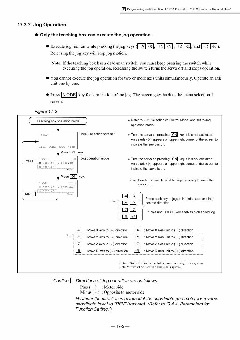
2 Programming and Operation of EXEA Controller “17. Operation of Robot Module”
— 17-5 —
17.3.2. Jog Operation
� Only the teaching box can execute the jog operation.
� Execute jog motion while pressing the jog keys ( +X -X , +Y -Y , +Z -Z , and +R -R ).Releasing the jog key will stop jog motion.
Note: If the teaching box has a dead-man switch, you must keep pressing the switch whileexecuting the jog operation. Releasing the switch turns the servo off and stops operation.
� You cannot execute the jog operation for two or more axis units simultaneously. Operate an axisunit one by one.
� Press MODE key for termination of the jog. The screen goes back to the menu selection 1screen.
Figure 17-2
-X : Move X axis to ( - ) direction. +X : Move X axis unit to ( + ) direction.
-Y : Move Y axis to ( - ) direction. +Y : Move Y axis unit to ( + ) direction.
-Z : Move Z axis to ( - ) direction. +Z : Move Z axis unit to ( + ) direction.
-R : Move R axis to ( - ) direction. +R : Move R axis unit to ( + ) direction.
MODE
Press F3 key.
Note 1: No indication in the dotted lines for a single axis systemNote 2: It won’t be used in a single axis system.
Press each key to jog an intended axis unit intodesired direction.
* Pressing HIGH key enables high speed jog.
-X +X
-Y +Y
-Z +Z
-R +R
Note: Dead-man switch must be kept pressing to make theservo on.
� Turn the servo on pressing ON key if it is not activated.An asterisk (�) appears on upper right corner of the screen toindicate the servo is on.
� Turn the servo on pressing ON key if it is not activated.An asterisk (�) appears on upper right corner of the screen toindicate the servo is on.
� Refer to “8.2. Selection of Control Mode” and set to Jogoperation mode.
: Jog operation mode
: Menu selection screen 1
Press ON key.
[MENU]
1RUN 2ORG 3JOG 4etc
[JOG] U1X 0000.00 Y 0000.00Z 0000.00
[JOG] U1 *X 0000.00 Y 0000.00Z 0000.00
MODE
Note 2
Note 2
Teaching box operation mode
Note 1
Note 1
Caution : Directions of Jog operation are as follows.Plus ( + ) : Motor sideMinus ( - ) : Opposite to motor side
However the direction is reversed if the coordinate parameter for reversecoordinate is set to “REV” (reverse). (Refer to “9.4.4. Parameters forFunction Setting.”)

2 Programming and Operation of EXEA Controller “17. Operation of Robot Module”
— 17-6 —
17.3.2.1. Sequential Timing of Jog Operation
Figure 17-3
Jog acceleration /deceleration
Jog speed
0.5 sec or more0.5 sec or less
ONOFFJog key
( -X or +X key, etc)
Jog Motion
Move 0.01mm.(0.1mm: in high speed jog motion.)
� Pitch feed of the jog operation is 0.01 mm when the jog keys are pressed for less than 0.5seconds. Pitch feed becomes 0.1 mm when HIGH key and the jog keys are pressedsimultaneously.
� The jog acceleration / deceleration, jog speed, and high jog speed must be specified to the initialsetting. Refer to “9.3.3. Parameters for Jog Operation.”
Note: When the response of the slider (start and stop) to on and off of the jog keys is dull,increase acceleration and deceleration of jog motion. It will give a crisp response.Overshoot may be observed if setting of acceleration / deceleration is too high. Set themto the safety speed (250 mm/s or less.)

2 Programming and Operation of EXEA Controller “17. Operation of Robot Module”
— 17-7 —
17.3.3. Programmed Operation by Teaching Box
17.3.3.1. Sequential Programmed Operation
� Once the robot module is started, the system continues sequential programmed operation to theend of the program. (to the END command of a program.)
� Step operation is available. Programmed step operation is to execute a step one by one bypressing START key.
� Starting sequential programmed operation
Figure 17-4
MODE
MODE
MODE
MODE
� Set the program number to be operated.(1) Select the number using keys, and confirm the
program number by pressing SET key.(2) Press F1 key and specify the program number
using the numeric keys and SET key then confirmit by pressing SET key.
� Select using , then confirm it by pressing SET key.
A: Sequential programmed operationS: Programmed step operation
Press ON key.
Press F1 key.
� When an alarm is detected in this state, the screen willindicate that an alarm is on. Take proper actions referringto “13. Alarms” and “14. Troubleshooting.”
� Refer to “8.2. Selection of Control Mode” and set to theprogrammed operation mode.
: Select sequential / step operation
: Programmed operation mode$ : Indicates that a program exists.TEST: Indicates the name of the program.(004) : Indicates how many steps are used.
: Menu selection screen 1[MENU]
1RUN 2ORG 3JOG 4etc
[RUN] 000$ TEST (004)
Mode(A)?
MODE
[Run] R 000/000 U1 T*X 0000.00 Y 0000.00Z 0000.001HLD [RA]
[Run] 000/000$ TEST (004)
Push START [SA]
[RUN] 000/000 *$ TEST (004)
Push START [SA]
� Press START key after this screen. The programmed
operation starts.
Press F2
key.
Press START key.
Press START key.
: This screen is displayed duringoperation.
: End of operation
[Menu]ALARM[F5] 000/000Prg(Origin not exe.)1RUN 2ORG 3JOG 4etc
� Refer to “17.3.1. Home Return.”
� An alarm will be issued whenHome return is not completed.
� Press F2 key and perform
Home return. Then follow thestarting procedure ofprogrammed operation again.
Pressing MODE key in the screen of programmed operation
mode will make to return to the menu selection screen 1.
Home return operation
� Press ON key. The system gets into servo on state and
� (asterisk) appears on upper right corner of screen toindicate “servo is on.”
� Select the screen for current position of each axis (thecoordinate data) using keys.
Teaching box operation mode
[RUN] 000$ TEST (004)
1prog
[Run] 000/000 *X 0000.00 Y 0000.00Z 0000.00Push START [SA]
Start
The executing of END commandcompletes the programmed operationand the screen on left is displayed.
Pressing START key will starts the
operation from the top of the programagain.
Indicates the program No. / step No.currently being executed.Switch on and off for an indication ofthe current position by or key.(X axis only for a single axis system.)

2 Programming and Operation of EXEA Controller “17. Operation of Robot Module”
— 17-8 —
� Stopping sequential programmed operation
� Table 17-1 below describes the stopping functions of a sequential programmed operation.
Danger : The stopping functions listed in Table 17-1, excluding the emergency stop,are valid for programmed operation only. In another operation mode, pressEMG key to stop operation in an emergency as the other functions are
not valid.
Table 17-1Function Description of function Procedure
Emergency stop� Stops a programmed operation immediately and the motor gets into “servo off”
state.* For emergency stop function, see “11.3.1. Emergency Stop.”
Press EMG key.
Forced stop
� Stops a programmed operation immediately (when moving, decelerates and stops).The system goes back to the top of the program and waits.
� The motor is in “servo lock” state.� Pressing START key starts the programmed operation from the top of program.Note: Execution of “forced stop” resets the data of data registers and internal
flags excluding the following.• Point coordinate data (P0000 ~ P3999)• General output data by OUT command.
Press STOP key.
Cycle stop
� Stops after completing the step being executed.� The motor gets in “servo lock” state.� Pressing START key resumes the programmed operation from the next step.
Note: If an alarm arises, or STOP or EMG key is pressed during cycle stop,the state of cycle stop is removed and the programmed operation cannotbe resumed.
Caution : If case of a multi-axis combination, cycle stop is not effectiveduring “continuous path” operation. It stops when thecontinuous path is completed.
Press CYCSTOPkey.
Hold
� Terminates motion command and decelerates and stops, and waits at the currentposition.
� The motor gets in “servo lock” state.� Pressing START key resumes the subsequent instructions (completes motion
command) and continues to execute following programmed operation.Note: If an alarm arises, or STOP or EMG key is pressed during “hold”
state, “hold” state is removed and remaining programmed operationcannot be resumed.
Press F1 key.
Caution : The display screen goes back to MENU screen by MODE key while aprogrammed operation continues. The system will immediately stop theoperation as soon as the mode is changed to “external control” mode.

2 Programming and Operation of EXEA Controller “17. Operation of Robot Module”
— 17-9 —
17.4. Operation in External Control Mode
� This mode is to operate the system through control output / input (CN3) and general input /output (EXT. IO).
� Turning on the main power gets into this mode automatically.
Caution : In external control mode, the teaching box does not function except thefollowing.
1) Emergency stop : Pressing EMG key leads to an emergency stop state.* Refer to “11.3.1. Emergency Stop.”
2) Mode selection : You may switch to teaching box operation mode using keys.Changing mode while executing the external mode will stopoperation immediately (if the slider is in motion, it decelerates andstops) and the system gets into servo lock state.
3) Monitoring programmed operation :You can monitor the state of programmed operation using F1 to F3keys.
Caution : Turn input EREM off to control through CN3 connector.
17.4.1. Operation Procedures in External Control Mode
Figure 17-5
: See “17.4.3. Home Return.”
: See “17.1. Power On and Off.”
: See “17.1. Power On and Off.”
: See “17.4.4. Programmed Operation.”
: See “17.4.2. Servo on.”
: See “17.4.5. StoppingProgrammed Operation.”
Servo on.
Turn power on.
Home return
Programmed OperationTerminateoperation
Turn Power off

2 Programming and Operation of EXEA Controller “17. Operation of Robot Module”
— 17-10 —
17.4.2. Servo on
� Servo on Input / Output
Table 17-2Signal Pin No. DescriptionSVON 8 Servo on input On : Servo on. Off: Servo offRDY 35 Ready output Opens at serious alarms. Normally closed.WRN 16 Alarm warning output Closes at minor alarms. Normally opened.
� The alarm outputs (RDY and WRN) are stabilized within a certain period of time after turningon power. (approximately 4 seconds for initializing CPU) Activate SVON input if no alarm isdetected. The motor servo is activated and is ready to receive the operation commands.
Caution : If an alarm arises, take proper measures referring to “13. Alarms” and“14. Troubleshooting.”
� In inactive state of SVON, the position error counter is cleared.
Figure 17-6
stabilized
Invalid duringCPU initialization
Approx. 1 sec.
(Time for CPU initialization)
closeopen
ONOFF
ONOFF
ONOFFPower
RDY and WRN output
SVON input
Motor servo
Note: (1) ON and OFF keys of the teaching box cannot switch Servo on / off in externalcontrol mode.
(2) When SVON input is on, execution of “servo off” command in a program makesSERVO off.When SERVON input is off, “servo on” command in a program is invalid.(Servo on / off command in a program: SRV command is valid only when SVONinput is active.)
(3) When SVON input is deactivated during a positioning operation (Home return orexecution of motion command in a programmed operation), the positioning operationis terminated, the servo is off, then an alarm arises.

2 Programming and Operation of EXEA Controller “17. Operation of Robot Module”
— 17-11 —
17.4.3. Home Return
� Please perform “Home return” for the first time you operate the system. Otherwise the systemcannot perform the programmed operation because it cannot specify the position coordinate data.
Note: Home return shall be performed in the following occasions. Home return is not necessaryin normal operation once the home position is established.
(1) At startup. (When the power is on for the first time.)(2) More than 20 minutes are passed after disconnection of the controller cable.(3) A battery (installed internally) for encoder back-up has discharged.(4) The setting of module main unit type is changed.(5) The power is turned off before the new setting in 4) is not saved. [SAV command in
CTR mode.](6) Resetting home position is interrupted by an emergency stop command, an alarm or
power failure.
� Input / Output of Home return operation
Table 17-3Signal Pin No. DescriptionSVON 8 Servo on input On: Turns Servo on. Off: Turns Servo off.HOS 25 Input: Start Home return Rising signal detection to on starts Home return.
HOMS 14 Output: Completion ofHome return Closes when Home return is completed.
MTN 34 Output: Executingoperation
Closes during the execution of programmed operation or Home return.Home return is enabled when this signal is opened. (while no programmedoperation)
STOP 26 Input: Forced stop A slider decelerates and stops when this signal is inputted during Home return.Home return cannot start while this signal remains on.
� Procedure of Home return
1) Turn the servo on referring to “17.4.2. Servo on.”
2) Make sure that STOP input is off and MTN output is open. If STOP input is on, Home returncannot be executed. Also, if MTN is closed (means an operation is underway.) Home returncannot be executed.
� Wait till the programmed operation ends or forcibly terminate the programmedoperation by inputting STOP signal. (Deactivate STOP signal after completion of theprogrammed operation.)
3) Turn on HOS input. Home return starts.
� The motor decelerates and stops when STOP input is turned on during Home return. Insuch a case, as Home return is not completed yet, turn off STOP input and start Homereturn again.
� Home return will be terminated when EMST input is off during the operation.
* Refer to “11.3.1. Emergency Stop.”
4) HOMS output will be closed at the end of Home return.
Note: (1) HOS input is detected at the rising edge of signal (effective at the rising point of offto on.). You cannot start Home return operation if HOS input is being on.
(2) HOMS output is not Home proximity signal. It is the signal for the end of Homereturn. Thereafter Home return has completed, it will be automatically closed afterthe initialization, even the power is turned off and turned on again.
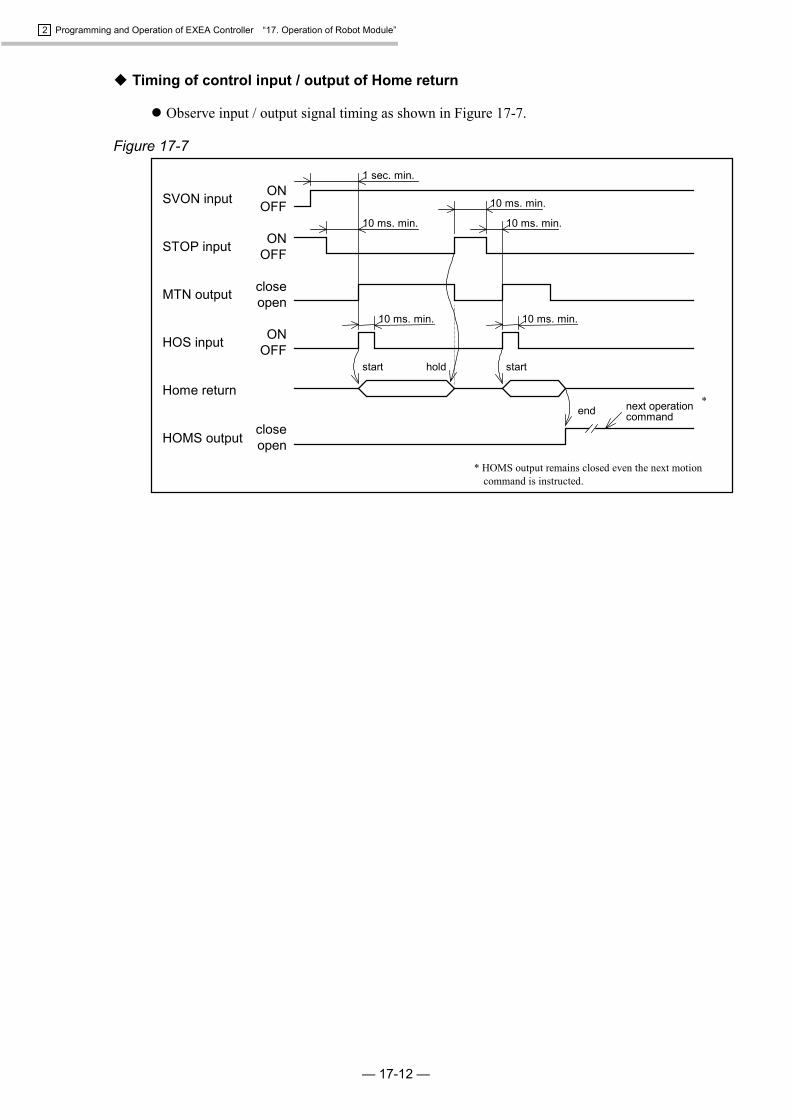
2 Programming and Operation of EXEA Controller “17. Operation of Robot Module”
— 17-12 —
� Timing of control input / output of Home return
� Observe input / output signal timing as shown in Figure 17-7.
Figure 17-7
10 ms. min.10 ms. min.
1 sec. min.
10 ms. min.
10 ms. min.10 ms. min.
hold start
ONOFF
ONOFF
closeopen
closeopen
ONOFFSVON input
STOP input
MTN output
HOS input
Home return
HOMS output
next operationcommandend
start
*
* HOMS output remains closed even the next motioncommand is instructed.

2 Programming and Operation of EXEA Controller “17. Operation of Robot Module”
— 17-13 —
17.4.4. Programmed Operation
� Input / Output for programmed operation
Table 17-4Pin No.Signal CN3 P1-EXT.I/O Description
SVON 8 – Input: Servo on On : Turn Servo on. Off : Turn Servo off.
RUN 7 – Input: Startprogrammed operation Starts a programmed operation when rising edge signal turns on.
Specify a program number to be operated by PROG 0 to 6 inputsin binary numbers.
0 : OFF 1 : ONProgram No.Input 0 1 2 · · · 127
PROG6 0 0 0 1PROG5 0 0 0 1PROG4 0 0 0 1PROG3 0 0 0 · · · 1PROG2 0 0 0 1PROG1 0 0 1 1PROG0 0 1 0 1
PROG0 to
PROG6– 8 to 10,
25 to 28Input: Program No.selection
MTN 34 – Output: Operationunderway Closes during operation. Opens when an operation ends.
CSTP 24 – Input: Cycle stop
Stops a cycle when it is on during a sequential programmedoperation.� Execute a programmed step operation if the command for a
programmed operation is inputted while this signal is on.
HOLD 5 – Input: Hold
It decelerates then stops a motion when it is on duringprogrammed operation.� If HOLD signal remains on, start command of a programmed
operation is not valid.
STOP 26 – Input: Forced stop
It decelerates then stops a motion when it is on duringprogrammed operation.� If STOP input remains on, start command of a programmed
operation is invalid.
CSTPA 32 – Output: Indicatescycle stop is on. It is closed during the state of cycle stop by CSTP input.
HOLDA 13 – Output: Indication ofhold It is closed during the state of hold by HOLD input.
� Refer to “17.4.5. Stopping Programmed Operation” for details.
� Procedures of programmed operation
1) Turn “servo on” referring to “17.4.2. Servo on.”
2) Execute Home return referring to “17.4.3. Home Return.”
3) Make sure that none of the inputs for termination of operation, such as CSTP, STOP and HLD,is on and MTN output is opened. You cannot start a programmed operation while STOP or HLDinputs is on.If MTN input is closed (= Programmed operation is under way.), you cannot start a newprogrammed operation.
� Wait till the programmed operation ends or forcibly terminate the programmedoperation by inputting STOP signal. (Deactivate STOP signal after completion of theprogrammed operation.)

2 Programming and Operation of EXEA Controller “17. Operation of Robot Module”
— 17-14 —
4) Specify a program number by inputs of program number selection.
5) Turn RUN input on. A programmed operation starts and MTN output is closed.
6) MTN output is opened when a programmed operation completes.
Note: (1) Once a programmed operation is started (= MTN output remains closing), theprogram selection input is not valid. If you want to change the program number, waittill the programmed operation completes or forcibly stop the programmed operationby inputting STOP signal.
(2) RUN input is detected at its rising edge signal (effective at the point of off to on). IfRUN input is being on, you cannot start a programmed operation.
� Timing of control input / output of programmed operation
� Observe signal timing as shown in Figure 17-8 below.
Figure 17-8
ONOFF
10 ms. min.
Program No. 0start start
Note (2)
Note (1)10 ms. min.
10 ms. min.
SVON input
STOP input
CSTP input
Program No. selection(PRG 0 to 6 input)
RUN input
Execute programmedoperation
HOM output
MTN output
General output
1sec. min.
10 ms. min.ON
OFF
ONOFF
closeopen
ONOFF
closeopen
Program No. 0 Program No. 2Program No. 1
step 0: step 1: step 2: step 0:step 3:
Changes by OUT command = Doesnot change till next OUT command.
All bits open rightafter the power on.
Changes by OUTcommand.
10 ms. min. 10 ms. min. 10 ms. min.
Program No. 2
MOVcommand
OUTcommand
MOVcommand
OUTcommand
ENDcommand
Note: (1) Once a programmed operation starts (= MTN output is closed), program numberselection is invalid until the end of the operation. It can be used as general input.
(2) Once a programmed operation starts (= MTN output is closed), RUN input is invaliduntil the end of the operation.

2 Programming and Operation of EXEA Controller “17. Operation of Robot Module”
— 17-15 —
17.4.5. Stopping Programmed Operation
� The system provides following functions to terminate programmed operation in the middle ofoperation in external control mode.
1) Emergency stop
2) Forced stop
3) Cycle stop in the middle of sequential operation
4) Hold
� Emergency stop procedure : EMST input off
� Terminate a programmed operation immediately. The motor is in the “servo lock” state.
* For function of the emergency stop, see “11.3.1. Emergency Stop.”
� Forced stop procedure : STOP input on
� Cease a programmed operation instantly (when the robot is in motion, the motor decelerates andstops) and the system returns to the top of the program and waits.
� The motor is in “servo lock” state.
� After STOP input is off, RUN input resumes the programmed operation from the top of theprogram.
� If STOP input remains on, RUN input is invalid.
Note: The execution of forced stop resets data register and internal flag data excluding thefollowing data.
� Data of point register : (P0000 to P3999)
� General output data by OUT command
� Cycle stop in the middle of sequential operation :Procedure : CSTP input on in the middle of sequential operation
� The system stops after completing the step being executed.
� CSTPA output is closed during the cycle stop.
� The motor is in servo lock state.
� RUN input after deactivation of CSTP input resumes the sequential operation from the next stepof the program.
� RUN input, keeping CSTP input on, starts programmed step operation from the next step.
Note: (1) During cycle stop, detection of an alarm, inputting STOP input or deactivation ofEMST input will cancel the cycle stop state. (= MTN output is opened because theprogram is ceased.) This disables to resume the programmed operation. If you try toresume the programmed operation in this state, it starts from the top of the program.(after releasing emergency stop when the system is in the emergency stop state.)
(2) Cycle stop is not accepted during a continue path motion. It is valid after thecontinue path has completed.

2 Programming and Operation of EXEA Controller “17. Operation of Robot Module”
— 17-16 —
� Procedure for hold : HOLD input on
� This is to cancel a motion command. It decelerates and stops the motion. HOLDA output isclosed. The system stands by at the position where it stopped.
� The motor is in servo lock state.
� In the hold state (when both outputs, HOLDA and MTN, are closed), input of RUN afterdeactivate HOLD input resumes the remaining motion from the stopped position, then continuesthe programmed operation.
� RUN input is invalid while HOLD input is on.
� If the cycle stop is on in the hold state, it resumes remaining motion of the step then stops theoperation.
Note: (1) During hold state, a detection of an alarm, activating STOP input or deactivatingEMST input will cancel the state (= MTN output is opened as the program is ceased.).This disables to resume the programmed operation. If you try to resume theprogrammed operation in this state, it starts from the top of the program. (afterreleasing emergency stop when the system is in the emergency stop state.)
(2) Input of HOLD command in the middle of a continuous path motion terminates themotion. The remain of the motion will be treated as an ordinal motion command, notas an continuous path motion.
(3) In the state of hold which is activated in the middle of execution of move command,deactivation of SVON input makes ‘servo off’ state, then an alarm will be given.(program error)
� Signal timing to terminate sequential programmed operation
Figure 17-9
10 ms min.
10 ms min.10 ms min.10 ms min.
10 ms min.
RUN input
CSTP input
STOP input
HOLD input
Execute programmedoperation
MTN output
HOLDA output
CSTPA output
ONOFF
ONOFF
ONOFF
closeopen
ONOFF
closeopen
closeopen
No. n+1 step No.0No. n+2No. n+1 No. n+4No. n+3step No. n
10 ms min.
10 ms min.10 ms min.
10 ms min.
remain ofNo. n+1
HOMcommand
LDcommand
MOVcommand
MOVcommand
MOVcommand
OUTcommand

2 Programming and Operation of EXEA Controller “17. Operation of Robot Module”
— 17-17 —
17.4.6. Operating Teaching Box
� Several operation status and data can be monitored using the teaching box in external controlmode.
1) Monitor of operation status
2) Input / output monitor
3) Monitor of software version and history of alarm
Figure 17-10: Screen of external control mode [External][External]
1RUN 2IO 3FNC 4etc
17.4.6.1. Monitor of Operation Status
� A screen to select monitor function appears when F1 key is pressed in “External” screen. Use keys to switch monitors of program name, number of program steps and current position.
Then, keys enable to select the unit number when the screen shows current position incase of multi-axis combination.
Figure 17-11: Operation monitor screen
[ERUN] 000/000 U1
X0000.00 Y0000.00
[ERUN] 000/000
$ ABC (007)
Name of program Number of steps
Unit number
Current position of each axisunit (coordinate data)
Program number currently executedand its number of steps
17.4.6.2. I / O Monitor
� A screen to monitor the status of input / output signal appears as shown below when F2 key
(IO) is pressed in the [External] screen. Use F1 ~ F4 keys to select a monitor screen.
� Items that can be monitored.INP : Input portOUT : Output portMEM : Imaginary I/O portLMT : Travel limit port
Figure 17-12: I/O monitor selection screen[EI/O]
1INP 2OUT 3MEM 4LMT

2 Programming and Operation of EXEA Controller “17. Operation of Robot Module”
— 17-18 —
1 Monitoring input port
1) Monitor input port.
� Monitor screen for the input port appears when F1 (INP) key is pressed on the selecting screenof I / O monitoring.
� I is indicated on the side of [EI/O] in this screen.
� Current state of four input ports is reported on 2nd and 3rd lines. Use and keys tomove the cursor.
� Name of input port, of which bit is indicated by the cursor, is displayed on 1st line.
� If more than four input ports were to be monitored, use and keys to scroll the screen.
Figure 17-13: Monitor screen of input port
[EI/O]I EMST00 00000000 0000000010 00000000 000000001CHK
Name of port
� Indication of the 2nd and 3rd lines are, from left to right, port number, status of the port andstatus of port of the port number +1.
� Port number is indicated by unit of 8 bit, as left side is bit 7 and right side is bit 0.
� Status of the port is indicated by 0 as off and 1 as on regardless the port logic (normally open orclose).
Figure 17-14: Monitor example of input port
00 00000000 00000000
Status ofport 00
Portnumber
Status ofport 01
bit0bit7

2 Programming and Operation of EXEA Controller “17. Operation of Robot Module”
— 17-19 —
2) Monitor status of input port.
� Setting screen of the input port appears when F1 (CHK) key is pressed in the monitor screen ofinput port status.
� The screen displays two kinds of state (current and changing state) on the 2nd and the 3rd lines. and keys move the cursor.
� Port name of which bit is indicated by the cursor is displayed on the 1st line.
� If more than two ports were to be monitored, use and keys to scroll the indications.
Figure 17-15: Screen to monitor input port state
[EI/O]I EMST
00 00000000 00000000
×××××××× ××××××××
1NRM 2RST
Name of port
� State of port indicated on 2nd and 3rd lines are shown below.
00 00000000 00000000
×××××××× ××××××××
Status ofport 00
Portnumber
State of current port
Status ofport 01
State of changing
� Changing state of port on the 3rd line shows the changes on a port after RDY output is on or F2(RST) key is pressed.
� Each bit corresponds one to one to the bit on the 2nd line.
� When status of a port changes 0 to 1 after start of monitoring, x changes to 1, while a port statuschanges 1 to 0 after start of monitoring, x changes to 0. A bit of which status is changed keeps itsindication until F2 (RST) key is pressed.(“Current port status” on 2nd line changes in real time basis.)
Figure 17-16: Example of changes of a port.
Startmonitoring 0
×
0
1
1
1
1
×
Startmonitoring 0
0
1
0
� The screen returns for monitoring input port by pressing F1 key (NRM) in the monitor screenof input port state.

2 Programming and Operation of EXEA Controller “17. Operation of Robot Module”
— 17-20 —
2 Monitoring output port
� Monitor screen for output port appears when F2 (OUT) key is pressed on the selecting screenof I / O monitoring.
� O is indicated on the side of [EI/O] in this screen.
� Current state of four output ports is reported on the 2nd and 3rd lines. Use and keys to move the cursor.
� Name of output port, of which bit is indicated by the cursor, is displayed on the 1st line.
� If more than four output ports were to be monitored, use and keys to scroll the screen.
Figure 17-17: Monitor screen of output port
[I/O]O RDY
00 00110000 00000000
10 00000000 00000000
1CHK 3USR
Name of port
� Functions and structure of indication are the same as that of input port. However, pressing F3key (USR) makes possible to switch temporarily on / off state of a bit, under which the cursor is,by 0 and 1 keys.
Figure 17-18
Press F3 key.
: Switch on / off state of bit, under which the cursor is, by 0 and 1 keys.
0 … Switches port to off.1 … Switches port to on.
* Regardless the logic of port (normally open or close), 0 is off and 1 is on forswitching state of port.
[I/O]0 RDY
00 00110000 00000000
10 00000000 00000000
1CHK 3SYS
[I/O]0 RDY
00 00110000 00000000
10 00000000 00000000
1CHK 3USR
� Setting is effective till pressing F3 key (SYS) again or MODE key. When the setting iscanceled, it returns to the former state.

2 Programming and Operation of EXEA Controller “17. Operation of Robot Module”
— 17-21 —
3 Monitoring imaginary I/O port
1) Monitor imaginary input/output port.
� Monitor screen for imaginary input and output port appears when F3 key (MEM) is pressed inthe selecting screen of I/O monitor.
� M is indicated on the side of [EI/O] in the screen.
� Current state of two imaginary I/O port is displayed on the 2nd and 3rd lines. Use and keys to move the cursor.
Figure 17-19: Monitor screen of imaginary I/O port[EI/O]M
0 00000000 00000000
1CHK
� Indications of 2nd line are, from left to right, port number, status of the port and status of port ofthe port number +1.
� Status of the port is indicated by unit of 8 bit, as left side is 7 and right side is bit 0.
� Status of the port is indicated by 0 as off and 1 as on regardless the port logic (normally open orclose).
Figure 17-20: Monitor examples of imaginary I/O port
00 00000000 00000000
Status ofport 00
Portnumber
Status ofport 01
bit0bit7
2) Monitor of imaginary I/O port status.
� Monitor screen of imaginary I/O port status appears when F1 key is pressed in the monitorscreen of imaginary I/O port.
� The screen displays two kinds of state, current and changing status, on the 2nd and the 3rd lines.Use and keys to move the cursor.
� Refer to “2) Monitor status of input port. in 1 Monitoring input port” for the way to monitorthe status of the port.

2 Programming and Operation of EXEA Controller “17. Operation of Robot Module”
— 17-22 —
4 Monitoring hardware travel limit
� This is to report the state of hardware travel limit (F3 alarm). Refer to “13.4.18. Travel Limit(Mechanical lock).”
� The monitor screen appears when F4 key (LMT) is pressed in the I/O monitor screen.
� L is indicated on the side of [EI/O] in the screen.
� The state of hardware travel limit of specified motion unit is indicated on the 2nd line of thescreen. Use and keys to move the cursor. The name of the travel limit, of which bit isindicated by the cursor, is displayed on the 1st line.
� Use and keys to move the cursor to scroll the screen if the motion units are more thantwo for a multi-axis combination.
� The functions and contents of indications are the same as the input port monitoring.
Figure 17-21: Indication of hardware travel limit state (Two axes combination)
[EI/O]L OTM U1
X00 Y00
1CHK
Name of limit
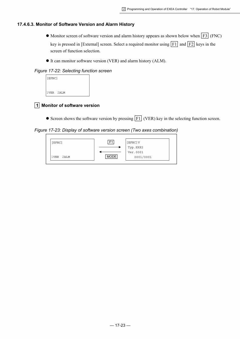
2 Programming and Operation of EXEA Controller “17. Operation of Robot Module”
— 17-23 —
17.4.6.3. Monitor of Software Version and Alarm History
� Monitor screen of software version and alarm history appears as shown below when F3 (FNC)
key is pressed in [External] screen. Select a required monitor using F1 and F2 keys in thescreen of function selection.
� It can monitor software version (VER) and alarm history (ALM).
Figure 17-22: Selecting function screen[EFNC]
1VER 2ALM
1 Monitor of software version
� Screen shows the software version by pressing F1 (VER) key in the selecting function screen.
Figure 17-23: Display of software version screen (Two axes combination)
[EFNC]V
Typ.EXE2
Ver.0001
0001/0001
[EFNC]
1VER 2ALM
F1
MODE

2 Programming and Operation of EXEA Controller “17. Operation of Robot Module”
— 17-24 —
2 Monitor of alarm history
� Alarm history is displayed by pressing F2 (ALM) key in the selecting function screen.
� Information on alarm histories are:On the 2nd line: history number, alarm code and alarm detection codeOn the 3rd line : name of alarm.
Newer the alarm, smaller the number. Refer to “Table 13-49 Contents of alarm history” in“13.7.2. Indication of Alarm History.”
� Alarm history is displayed by pressing key.
� Use F2 key to switch indication of an motion axis or a amplifier number in the alarm detectioncode on which an alarm is reported.
Figure 17-24: Display of alarm history screen
[EFNC]A
01 A5 U1XY
Encoder2(position)
1CLR 2AMP
[EFNC]
1VER 2ALM
F2
MODE
[EFNC]A
01 A5 A12
Encoder2(position)
1CLR 2AXS
F2
Name of alarm
History number
Alarm code
Alarm detection code(Amplifier on which an alarm is reported)U1XY � Alarm on X and Y axis of Unit 1A12 � Alarm on amplifier 1 and 2
� F1 (CLR) key in the monitor screen clears alarm history.

2 Programming and Operation of EXEA Controller “17. Operation of Robot Module”
— 17-25 —
17.5. Operational Function
17.5.1. Home Return
17.5.1.1. Function of Home Return
� Table 17-5 shows functions of Home return.
Table 17-5: List of Home return functionItem Refer to: Description
Direction to searchmechanical stopperposition
9.3.2. Parameters forHome Return Operation
� Specifies moving direction to search position of mechanical stoppers.(motor or opposite side to the motor) The shipping set is motor side.
Home position offset 9.3.2. Parameters forHome Return Operation
� If “Home position offset” has been set, the Home return operationcompletes after moving “off-set” distance from the defined Home position.
� The factory set is 0 (zero).
Stan-by position 9.3.2. Parameters forHome Return Operation
� If stand-by position is set, Home return completes after moving to theset position from defined Home position.
Coordinate direction 9.4.1.1. Parameter forServo
� Specify the + (plus) and - (minus) direction of the coordinate.� Factory set is + (plus) for opposite to motor side and - (minus) for
motor side.
Order to searchposition ofmechanical stopper *
9.3.2. Parameters forHome Return Operation
� You may set Home return in two ways, to perform it one by one axis,or all axes simultaneously.
� You may set precedence of axes for “one by one” Home return.Shipping set is to perform “all axes simultaneously.”
SpeedAcceleration/decelerationMechanical stoppersearching speed
9.3.2. Parameters forHome Return Operation
� Specify the speed, acceleration and deceleration of Home return.� Factory set Speed : 20 mm / sec
Acceleration / Deceleration : 0.5 m /s2
Mechanical stopper search speed : 1 mm / sec
* Not applicable for a sigle axis system.
17.5.1.2. Outline of Home Return
� The slider of a module main unit starts to the motor side* for Home return and reverses itsmotion when it hits the mechanical stopper. Then it stops at the first origin position of absoluteencoder and sets Home position.
* It moves to opposite side of motor when the setting is made to reversed direction or the motormounting parameter (direct or indirect mount) is not compatible to the module main unit.
Figure 17-25: Home return
The origin of absolute coordinate(If Home position offset is applied, the origin of absolute coordinateis set after the slider moved to the off-set Home position.)
Moving distance if Homeposition off-set or stand-by position is specified.
The first origin frommechanical stopper
Start Home return
Mechanical stopper
Origin of absoluteencoder
Speed of slider 0
ONOFF
ONOFF
Searching speedHome return speed
Home return speedAcceleration / deceleration of Home return

2 Programming and Operation of EXEA Controller “17. Operation of Robot Module”
— 17-26 —
17.5.1.3. Signal Timing of Home Return (Multi-axis combination only)
� Motion of individual axis unit is described in “17.5.1.2. Outline of Home Return.” The followingdescribes Home return in a multi-axis combination.
� Example: Home return sequence in Z axis unit ���� Y axis unit ���� X axis unit(Three axes combination)
1) Z axis unit starts Home return and stops when it hits the mechanical stopper.
2) Y axis unit starts Home return and stops when it hits the mechanical stopper.
3) X axis unit starts Home return and stops when it hits the mechanical stopper. All axis units stopat the position of its mechanical stopper. Then Z axis unit starts to reverse its motion to theorigin of Z axis absolute encoder.
4) Z axis unit stops at the origin of absolute encoder and defines there as the Home position.
5) Then Y axis unit does the same and X axis unit follows.
6) The Home return operation is completed when the Home positions of all axis units are specifiedand HOMS output (CN3) is closed.
Figure 17-26: Example: Sequential Home return in order of Z axis unit � Y axis unit � X axis unit
Start Home return
Z axis unit slider speed
Z axis unitmechanical stopper
The origin of Z axisabsolute encoder
Y axis unit slider speed
Y axis unitmechanical stopper
The origin of Y axisabsolute encoder
X axis unit slider speed
X axis unitmechanical stopper
The origin of X axisabsolute encoder
HOMS output(CN3)
0
ONOFF
ONOFF
0
ONOFF
0
closeopen
ONOFF
The origin ofX axis
The origin of Y axis
The origin of Z axis
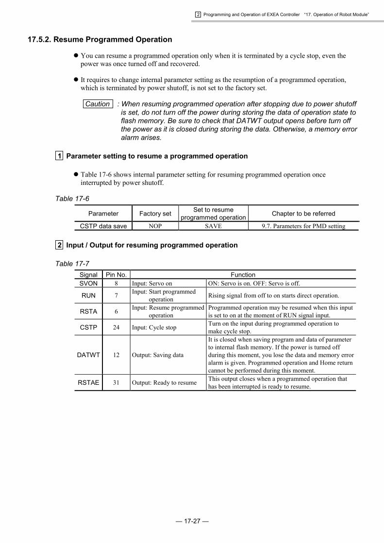
2 Programming and Operation of EXEA Controller “17. Operation of Robot Module”
— 17-27 —
17.5.2. Resume Programmed Operation
� You can resume a programmed operation only when it is terminated by a cycle stop, even thepower was once turned off and recovered.
� It requires to change internal parameter setting as the resumption of a programmed operation,which is terminated by power shutoff, is not set to the factory set.
Caution : When resuming programmed operation after stopping due to power shutoffis set, do not turn off the power during storing the data of operation state toflash memory. Be sure to check that DATWT output opens before turn offthe power as it is closed during storing the data. Otherwise, a memory erroralarm arises.
1 Parameter setting to resume a programmed operation
� Table 17-6 shows internal parameter setting for resuming programmed operation onceinterrupted by power shutoff.
Table 17-6
Parameter Factory set Set to resumeprogrammed operation Chapter to be referred
CSTP data save NOP SAVE 9.7. Parameters for PMD setting
2 Input / Output for resuming programmed operation
Table 17-7Signal Pin No. FunctionSVON 8 Input: Servo on ON: Servo is on. OFF: Servo is off.
RUN 7 Input: Start programmedoperation Rising signal from off to on starts direct operation.
RSTA 6 Input: Resume programmedoperation
Programmed operation may be resumed when this inputis set to on at the moment of RUN signal input.
CSTP 24 Input: Cycle stop Turn on the input during programmed operation tomake cycle stop.
DATWT 12 Output: Saving data
It is closed when saving program and data of parameterto internal flash memory. If the power is turned offduring this moment, you lose the data and memory erroralarm is given. Programmed operation and Home returncannot be performed during this moment.
RSTAE 31 Output: Ready to resume This output closes when a programmed operation thathas been interrupted is ready to resume.

2 Programming and Operation of EXEA Controller “17. Operation of Robot Module”
— 17-28 —
17.5.2.1. Procedure to Resume Programmed Operation in External Control Mode
1) Stop programmed operation by turning CSTP input on. Turn off SVON input and turn off thepower after confirming that output of DATWT is open.
2) Recover the power then put on SVON signal. Confirm that RATAE output is closed. TurnRATAE signal on, then restart the program by RUN signal.
Note: As RUN signal is detected in the rising current from off to on, the program cannot start ifRUN has been on from the beginning.
� If RUN signal is on without turning on RSTA signal, the program starts its operation from thetop, same as a normal operation. In this case, data registers D000 to D099 will be initialized,while data registers D100 to D199 will retain their state. If RUN signal is on after turning onRSTA signal, all data registers D000 to D199 will retain their state before the power was off.
� If RSTA command* is set to the top of an interrupted program, its programmed operationresumes after initializing program for recovery,* which is specified by RATA command,* isexecuted.
� If the position of starting operation and the state of general input are required to go back to thecondition when the program is interrupted, it can be done by an initializing program forrecovery.*
* Refer to “15.2.7. Description of Program Command” for RSTA command andinitializing program for recovery.

2 Programming and Operation of EXEA Controller “17. Operation of Robot Module”
— 17-29 —
1 Timing of control Input / Output of resuming programmed operation ----- 1
RSTA command (initializing program for recovery) is not set.
Figure 17-27
ONOFF
Output is fixed after CPU is initializedfollowing the power is on.
Result of setting byOUT command
10 ms min.
Power for controller
DATWT output
CSTP input
RSTAE output
RSTA input
RUN input
General output
Execute programmedoperation
closeopen
closeopen
ONOFF
ONOFF
ONOFF
10 ms min.
Programmedoperation interrupted Resume
Program step No. n+1program step No. n
All bit off: retain to the nextOUT command
10 ms min.

2 Programming and Operation of EXEA Controller “17. Operation of Robot Module”
— 17-30 —
2 Timing of control Input / Output of resuming programmed operation ------- 2
RSTA command (initializing program for recovery) is set.
Figure 17-28
ONOFF
Output is fixed after CPU isinitialized following the power is on
10 ms min.
Power for controller
DATWT output
CSTP input
RSTAE output
RSTA input
RUN input
General output
Execute programmedoperation
closeopen
closeopen
ONOFF
ONOFF
ONOFF
10 ms min.
Programmedoperation interrupted. Resume
n+1
00101101 00101101
Program step No. n
Example of RSTA command execution(initializing program for recovery)
All bit off
Put back generaloutput to state before
Move to interruptedposition.
10 ms min.

2 Programming and Operation of EXEA Controller “17. Operation of Robot Module”
— 17-31 —
17.5.2.2. Procedure to Resume Programmed Operation in Teaching Box Control Mode
Figure 17-29
: The data are saved to the flash memory.Do not turn off power. Otherwise thememory error is given.
Press CYCSTOP key for cycle stop.
: Executing programmed operation
SET : Selectionsequential operation/ step operation.
Press F1 key. Numeric key orSET for selecting Program number.
(Selected normal operation)
Press F2 key.(Select resuming operation)
Press SET key.
Press START key.
Press START key.
Press SET key.
Press MODE key
Press STOP * key
Press F1 key.
[Run] RSTA *
Push START [SA]
[Run] RSTA *
1prog
Resuming programmed operation.
[RUN] 000/000 *
Push START [SA]
[RUN] 000/000 *
Push START [CA]
[RUN]R 000/ T*
1HLD [RA]
[RUN]R 000/000 T*
Cycle stop [RA]
Shut- off power
Turn off Servo.
Recover the power
Set to Teaching box operating mode.
Turn Servo on.
[Menu] *
1RUN 2ORG 3JOG 4etc
[Run] 000 *
1prog 2rsta
[Run] 000 *
1prog 2rsta
[Run] 000 *
Mode(A)?
[RUN] 000/000 *
Push START [SA]
Normal operation from the top of the program.
� It is possible to resume a programmed operation when the program is interrupted byMODE key without turning off the power after the end of cycle stop.

2 Programming and Operation of EXEA Controller “17. Operation of Robot Module”
— 17-32 —
17.5.3. Output of In-position
� FIN signal may be set to P1-EXT. IO connector. (Refer to “9.9.1.Parameter List.”)
Note: The factory set does not set FIN signal to PI-EXT-IO connector. Also FIN signal cannotbe outputted as the parameter to set signal for completion of positioning (Fin control) areset to OFF.Turn Fin control ON in “9.3.1. Parameters for Programmed Operation” and set FIN signalreferring to “9.9. Parameters for Output Signal Format.”
� As an in-position signal format, you may select either FIN or COIN format.
Table 17-8Format Function Way of selection Factory set
FIN format One-shot output signal which closes for aspecified time after end of positioning.
Specify Fin out time* numerically.(Set other than OFF.)
�
(0.1)COINformat
Output format that opens during motionand closes after end of positioning. Set Fin out time* to OFF. –
* Refer to “9.3.1. Parameters for Programmed Operation.”
Note: (1) FIN output does not change by a command other than a motion command.(such as Jump and General output command, etc.)
FIN format ------------- Remains openCOIN format----------- Remains close
(2) End of positioning output is on after completion of all motion commands in acontinuous path operation. FIN output does not change in every end of motioncommand in continuous path operation. (Multi-axis combination)
� FIN output closes for a specified time when the motion command is completed and the error ofposition error counter reaches less than a specified value. Proceed to the next step after end ofFIN output.
� Specify detecting width of end of positioning (Finish width) and a closing time of FIN output ininitial setting referring to “9.3.1. Parameters for Programmed Operation.”
Figure 17-30
TimeMotion speed(Velocity profile)
Position error counter
FIN output(FIN format)
FIN output(COIN format) Move to the next
step at this moment.
Move to the nextstep at this moment.
Detection setting ofend of positioning(Finish width)
Motion speed
0
closeopen
closeopen
Closes when motion command starts.
Specified time to initial setting(Fin out time)
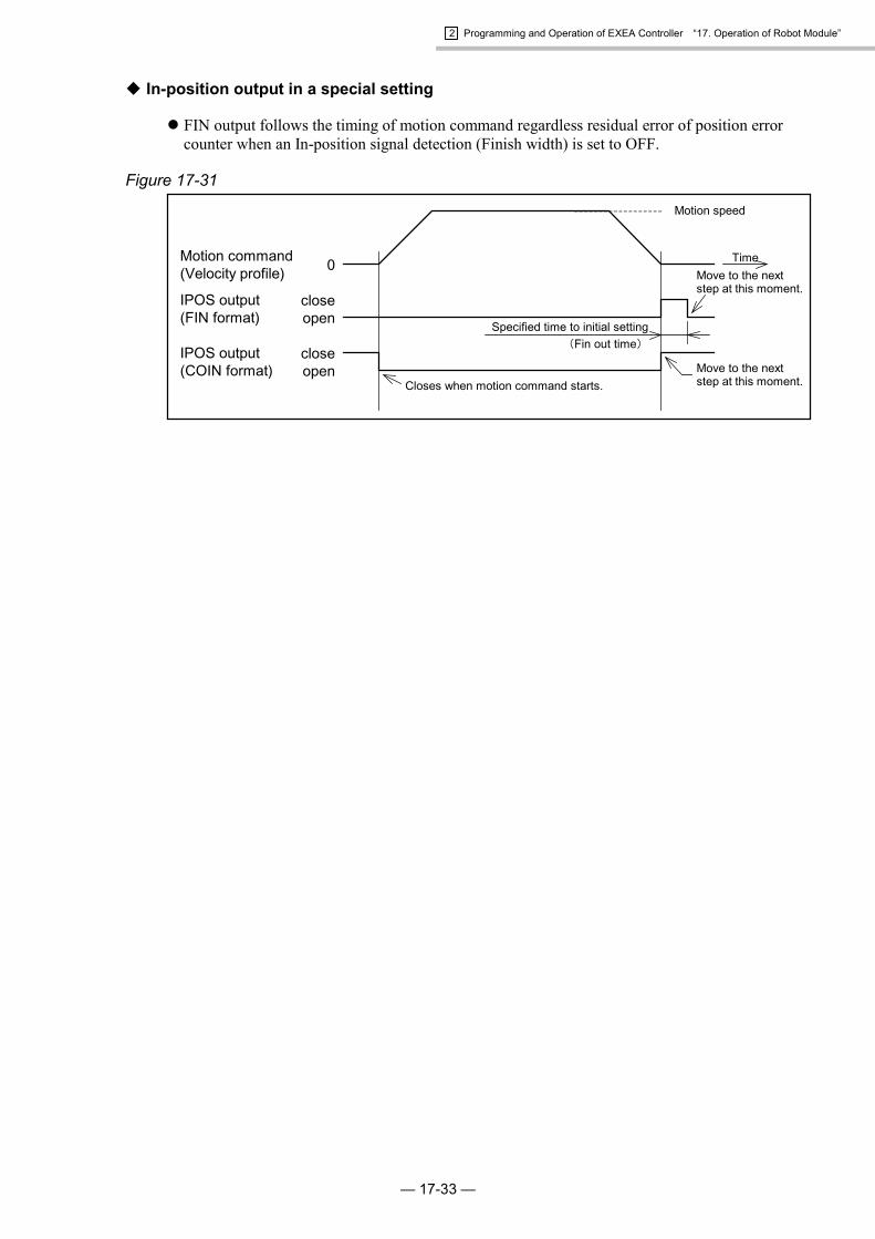
2 Programming and Operation of EXEA Controller “17. Operation of Robot Module”
— 17-33 —
� In-position output in a special setting
� FIN output follows the timing of motion command regardless residual error of position errorcounter when an In-position signal detection (Finish width) is set to OFF.
Figure 17-31
TimeMotion command(Velocity profile)
IPOS output(FIN format)
IPOS output(COIN format) Move to the next
step at this moment.
Move to the nextstep at this moment.
Motion speed
0
closeopen
closeopen
Closes when motion command starts.
Specified time to initial setting(Fin out time)

2 Programming and Operation of EXEA Controller “17. Operation of Robot Module”
— 17-34 —
17.5.4. Pulse Train Input (Single axis system only)
17.5.4.1. Function of Pulse Train Input
� The function of pulse train input is described in Table 17-9 below.
Table 17-9: Function list of pulse train input
Item Section to be referred forsetting Description
Resolution of pulsetrain input
“9.3.5. Parameters for PulseTrain Input”
� You may set the motion resolution for one pulse in pulse train inputoperation.
Factory set : 0.010 mm / pulse
17.5.4.2. Description of Operation
� The operation of pulse train input can be available when the following conditions are met.
1) In the external operation mode TBXM output = open
2) Controller is ready. RDY output = close
3) Not in motion MTN output = open
4) No in remote control mode EREM input = off
5) Servo is on. SVON = on
� The moving distance for a pulse may be selected from three styles below by setting the pulsetrain input resolution (Pulse resolution).
1) 0.01 ~ 0.10 mm
2) Ball screw lead
( Encoder resolution× speed reduction ratio )mm
3) Pulse train invalid (Disregard input pulse.)
� Programmed operation and Home return are possible in the pulse train input operation. However,do not use the start commands (RUN and HOS) in the pulse train input operation.
� When turning on the servo of a main unit which is incorporated motor brake, there may beapproximately 100 ms time lag to release a magnetic brake of the motor. Do not input the pulsesat that moment.

2 Programming and Operation of EXEA Controller “17. Operation of Robot Module”
— 17-35 —
17.5.4.3. Input Timing
Caution : The timing specified in Figure 17-32 is to receive the pule train input.There is another restriction such as the maximum speed. Adjust afrequency of pulse train for the allowable speed of a main unit.
Figure 17-32
CWP input
CCWP input
on
off
on
off
1.5µs or less
1.5µs or less
1.5µs or less
CW rotation CCW rotation

2 Programming and Operation of EXEA Controller “17. Operation of Robot Module”
— 17-36 —
(Blank Page)
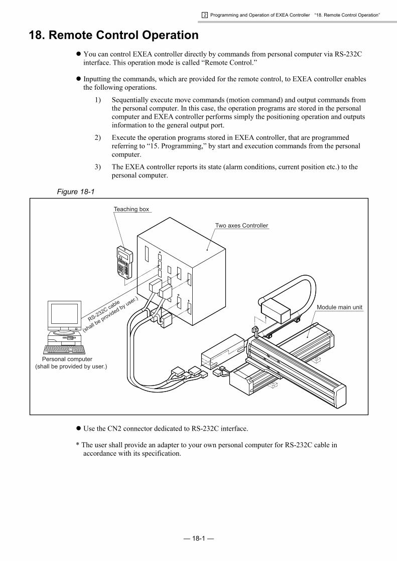
2 Programming and Operation of EXEA Controller “18. Remote Control Operation”
— 18-1 —
18. Remote Control Operation� You can control EXEA controller directly by commands from personal computer via RS-232C
interface. This operation mode is called “Remote Control.”
� Inputting the commands, which are provided for the remote control, to EXEA controller enablesthe following operations.
1) Sequentially execute move commands (motion command) and output commands fromthe personal computer. In this case, the operation programs are stored in the personalcomputer and EXEA controller performs simply the positioning operation and outputsinformation to the general output port.
2) Execute the operation programs stored in EXEA controller, that are programmedreferring to “15. Programming,” by start and execution commands from the personalcomputer.
3) The EXEA controller reports its state (alarm conditions, current position etc.) to thepersonal computer.
Figure 18-1
� Use the CN2 connector dedicated to RS-232C interface.
* The user shall provide an adapter to your own personal computer for RS-232C cable inaccordance with its specification.

2 Programming and Operation of EXEA Controller “18. Remote Control Operation”
— 18-2 —
18.1. Interface Specification
Table 18-1Transmission Full duplexCommunication speed 9600 bpsData length 8 bitStop bit 2 bitParity check None
Communication control X parameter ----------------------- noneControl signal (RTS, CTS)------ available
18.2. Outline of Remote Control
18.2.1. Outline
� When the personal computer inputs a command to EXEA controller in the remote control mode,it returns some signals in accordance with the commands to the personal computer.
Figure 18-2
Personal computer
EXEA controller
Response: RS-232C interface
Command
� Commands and responses are written in ASCII coded characters. For details of command andresponse, refer to “18.4.2. Description of Command.”
� Put CR (carriage return) code to the end of commands. CR code concludes the command.

2 Programming and Operation of EXEA Controller “18. Remote Control Operation”
— 18-3 —
� The commands in remote control are classified into three categories as shown below.(Refer to Figure 18-3.)
First level command : A command itself has the meaning and is alwaysexecutable such as instructing “Servo on” or “Emergencystop.”
Mode declaration command : This is to declare to use second level command.Second level command : This command can be executed when it is specified the
command mode by a mode declaration command.
Figure 18-3
First level command
Mode declaration command
Second level command Impossible to carry out.
First level command
Second level command
Lifting mode declaration command
First level command
Second level command Impossible to carry out.
Possible to carry out.
Possible to carry out.
� A normal second level command is carried out after specifying command mode. However, youcan combine the two commands, mode declaration and second level command, into one string ofcommand characters and execute them. (Refer to Figure 18-4.)
Figure 18-4
Mode declaration command : Second level command CR
� Each second level command belongs to a command mode. It cannot be used under differentcommand mode. Be careful that, in some mode declaration commands, there may be the samename second level commands with different function. To complete the current command mode,it is necessary to execute the command to remove declaration (QUIT command) or performother mode declaration command.
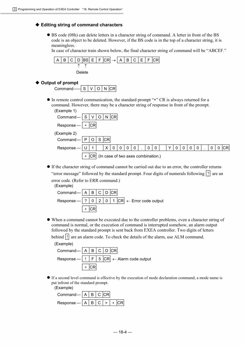
2 Programming and Operation of EXEA Controller “18. Remote Control Operation”
— 18-4 —
� Editing string of command characters
� BS code (08h) can delete letters in a character string of command. A letter in front of the BScode is an object to be deleted. However, if the BS code is in the top of a character string, it ismeaningless.In case of character train shown below, the final character string of command will be “ABCEF.”
A B C D BS E F CR � A B C E F CR� �
Delete
� Output of promptCommand----- S V O N CR
� In remote control communication, the standard prompt “�” CR is always returned for acommand. However, there may be a character string of response in front of the prompt.
(Example 1)Command--- S V O N CR
Response --- � CR
(Example 2)Command--- P O S CR
Response --- U 1 X 0 0 0 0 . 0 0 Y 0 0 0 0 . 0 0 CR
� CR (In case of two axes combination.)
� If the character string of command cannot be carried out due to an error, the controller returns“error message” followed by the standard prompt. Four digits of numerals following ? are anerror code. (Refer to ERR command.)
(Example)Command--- A B C D CR
Response --- ? 0 2 0 1 CR � Error code output
� CR
� When a command cannot be executed due to the controller problems, even a character string ofcommand is normal, or the execution of command is interrupted somehow, an alarm outputfollowed by the standard prompt is sent back from EXEA controller. Two digits of lettersbehind ! are an alarm code. To check the details of the alarm, use ALM command.
(Example)Command--- A B C D CR
Response --- ! F 5 CR � Alarm code output
� CR
� If a second level command is effective by the execution of mode declaration command, a mode name isput infront of the standard prompt.
(Example)Command--- A B C CR
Response --- A B C > � CR

2 Programming and Operation of EXEA Controller “18. Remote Control Operation”
— 18-5 —
18.2.2. Caution for Remote Control
� CN3: Control Input / Output
� When getting into the remote control mode, activate EREM input of CN3 control input. In theremote control operation, all CN3 control input excluding EMST input are invalid. The controloutputs are activated in the same manner as in the external control mode.
� Servo ON / OFF
� The motor must be in “servo on” state to execute a move command or perform a move commandin programmed operation by RUN input. Make the motor in servo on by inputting SVONcommand, then input a move command.
Note : If a move command is inputted when the servo is off, the EXEA controller returnsabnormal message and gets into the alarm state.
� Error response
� Input of a character unspecified in the command or a command which is restricted to enter willhave “error response” from EXEA controller.
� Returns a character string start with ? .
� When an alarm is detected in EXEA controller in the middle of operation, or when a commandto lead an alarm is inputted, EXEA controller returns “error response.”
� Returns a character string start with ! .

2 Programming and Operation of EXEA Controller “18. Remote Control Operation”
— 18-6 —
18.3. Startup of Remote Control
18.3.1. Startup Procedure
Figure 18-5.
: Initialize SET in SYS mode and SET in CTR mode referring to “9.Initial Setting.“ Refer to the SET in “18.4.2.8. SYS Mode • SecondLevel Command” and “ 18.4.2.9. CTR Mode • Second Levelcommand.”
Caution : Do not turn EREM input off during the remote control mode.Otherwise the motion commands of external control mode willbe accepted.
: (1) Make sure that there is no miss-wiring and turn on the main power.For turning on and off the main power, see “17.1. Power On andOff.”
: (2) Turn on EMST input (normally close) and EREM input.
: (1) Connect your personal computer and EXEA controller with RS-232C cable. Refer to “7.4. CN2: RS-232C Connector” for thecable. (The user must provide RS-232C cable.)
(2) Wire CN3 EMST input and EREM input.
Note : EMST input is valid even in the remote control mode.The system stays in “emergency stop” state unless EMSTinput is not processed.
Initialize
Turn on power
Wiring / preparation

2 Programming and Operation of EXEA Controller “18. Remote Control Operation”
— 18-7 —
18.4. Operation Command of Remote Control
18.4.1. Command List
Table 18-2 (1/2)Classification Command Description
SVON Activates the motor servo.Cannot carry out a motion command if the servo is off.
SVOF Deactivates the motor servo.EMST � Emergency stopACLR Clears alarms currently issued.VER � Displays the system reference number.ERR � Reports an error information in the communication.ALM � Reports alarms currently issued.POS � Indicates current position.IOP � Indicates status of input and output ports.
OperationalCommand
(First level command)
UNT �* Indicates the number of operating units.Withdrawal mode
declaration QUIT * Cancels the mode declaration.
MOT Gets in the remote control operation mode.SPD Sets motion speed and acceleration / deceleration.TYP Sets the format of motion.NOF Specifies offset value of position register.PBS Specifies the starting point.ESCZ * Specifies the prohibited area for motion of Z axis.SRV Switches servo on / off.HOM Starts the Home return.MOV Starts the linear interpolation. **MOVM Starts the continuous linear interpolation. ** (multi-point)ARC * Starts the arc interpolation (defined by three points).CIR * Starts the circular interpolation (defined by three points).MSTP Stops operation.MSPD Changes speed and acceleration.MSTS Reads out the state of motion.PALI Initializes pallet data.PALM * Starts palletizing.PALN * Specifies palletizing position number.QSTS * Reads out the status of palletizing.LDS Reads out the system state.LD Substitutes data.CAL Calculates data.TCH Substitutes current coordinate data for specified variable.OUT Controls output port.INP Reads out state of input port.LCAL Executes logical operation of data.
Mode DeclarationCommand
andSecond Level
Command
MOTmode
DAT � Indicates state of variables.� Effective command even the EREM input is off.* Not applicable for a single axis system.** In a single axis system, it will be a linear motion.
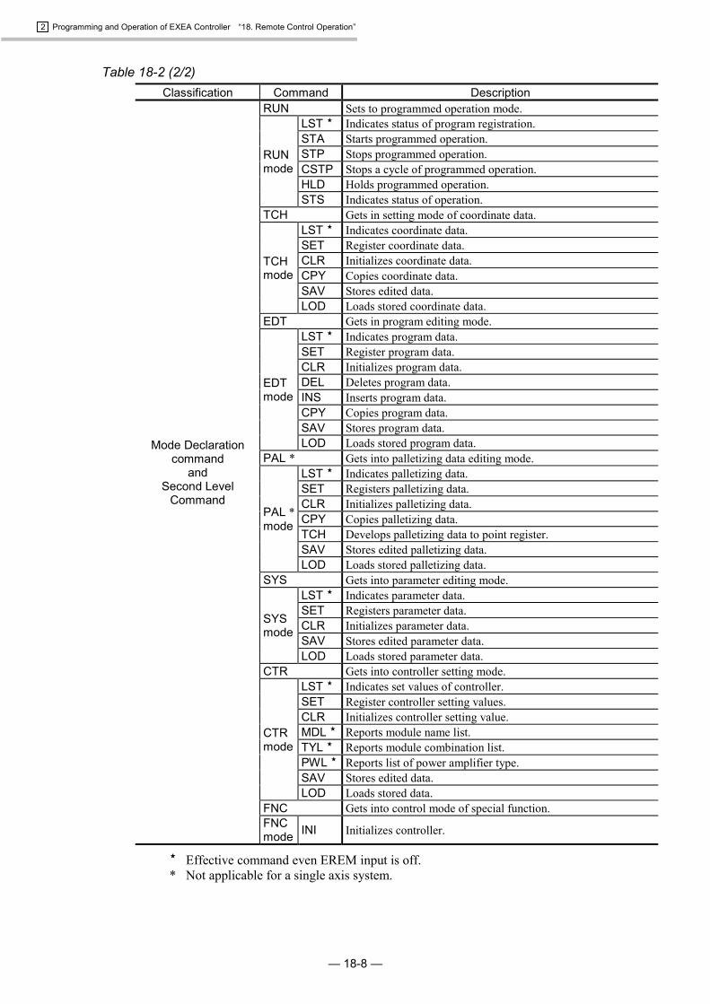
2 Programming and Operation of EXEA Controller “18. Remote Control Operation”
— 18-8 —
Table 18-2 (2/2)Classification Command Description
RUN Sets to programmed operation mode.LST � Indicates status of program registration.STA Starts programmed operation.STP Stops programmed operation.CSTP Stops a cycle of programmed operation.HLD Holds programmed operation.
RUNmode
STS Indicates status of operation.TCH Gets in setting mode of coordinate data.
LST � Indicates coordinate data.SET Register coordinate data.CLR Initializes coordinate data.CPY Copies coordinate data.SAV Stores edited data.
TCHmode
LOD Loads stored coordinate data.EDT Gets in program editing mode.
LST � Indicates program data.SET Register program data.CLR Initializes program data.DEL Deletes program data.INS Inserts program data.CPY Copies program data.SAV Stores program data.
EDTmode
LOD Loads stored program data.PAL * Gets into palletizing data editing mode.
LST � Indicates palletizing data.SET Registers palletizing data.CLR Initializes palletizing data.CPY Copies palletizing data.TCH Develops palletizing data to point register.SAV Stores edited palletizing data.
PAL *mode
LOD Loads stored palletizing data.SYS Gets into parameter editing mode.
LST � Indicates parameter data.SET Registers parameter data.CLR Initializes parameter data.SAV Stores edited parameter data.
SYSmode
LOD Loads stored parameter data.CTR Gets into controller setting mode.
LST � Indicates set values of controller.SET Register controller setting values.CLR Initializes controller setting value.MDL � Reports module name list.TYL � Reports module combination list.PWL � Reports list of power amplifier type.SAV Stores edited data.
CTRmode
LOD Loads stored data.FNC Gets into control mode of special function.
Mode Declarationcommand
andSecond Level
Command
FNCmode INI Initializes controller.
� Effective command even EREM input is off.* Not applicable for a single axis system.

2 Programming and Operation of EXEA Controller “18. Remote Control Operation”
— 18-9 —
18.4.2. Description of Command
� This section is to describe the function of command and its communicating data.
� [Multi-axis] is indicated on the right side of a command name that is only applicable to themulti-axis combination. A command with no indication is common to the multi-axiscombination and the single axis system.
� Function of command of which name is the same as program command has basically the samefunction as well.
� A command mode, to which a second level command belongs, is indicated on the left side of itsname.
18.4.2.1. First Level Command
SVON: Servo on
� This command makes the system ready for “Servo on.” However, when the SRV command(programmed operation or remote control command) has set to servo-off, the system cannot getin servo on.
Command----- S V O N CR
Response ----- � CR
� When switching servo state through remote communication is prohibited (CN3: EREM input isoff to prohibit remote control), input of SVON command will lead to an error state.
Command----- S V O N CR
Response ----- ? 0 2 0 2 CR
� CR
SVOF: Servo off
� Makes the system in “servo off” state. (prohibitive state of servo on)Command----- S V O F CR
Response ----- � CR
� When switching servo state through remote communication is prohibited (CN3: EREM input isoff to prohibit remote control.), input of SVOF command will lead to an error state.
Command----- S V O F CR
Response ----- ? 0 2 0 2 CR
� CR
EMST: Emergency stop
� Puts the system into the emergency stop state.Command----- E M S T CR
Response ----- � CR

2 Programming and Operation of EXEA Controller “18. Remote Control Operation”
— 18-10 —
ACLR : Alarm clear
� Clears the program error alarms which are activated in EXEA controller.Command----- A C L R CR
Response ----- � CR
� To clear all alarms in EXEA controller, add “ALL” following to ACLR command.(There are some commands that cannot be cleared by this command.)
Command----- A C L R A L L CR
Response ----- � CR
VER: Report reference number
� Reports the system reference number.Command----- V E R CR
Response ----- T y p . E X E 3 CR (In case of 3 axes controller)
V e r . 0 0 0 1 . 0 CR
0 0 0 1 . 0 / 0 0 0 1 . 0 CR
� CR
ERR: Read out error state
� Reports the current error state in the remote communication.
Note: The error codes reported by this command are listed in Table 18-3. Be aware that an erroris not an alarm arisen in the EXEA controller, but an error in the remote communication.
Command----- E R R CR
Response ----- 0 0 0 0 CR � Indication of an error code.
� CR
� Adding “ALL” to the end of the command will make to report the history of error state (eightmaximum). It reports error code in reverse order of occurence. Each error report is accompaniedby its history code.
Command----- E R R A L L CR
Response ----- 1 0 0 0 0 CR � Indication of an error code.�
8 0 0 0 0 CR � Indication of an error code.
� CR
� Adding a numeral from 1 to 8 as an error code to the command is to report the history ofspecified error code. The numeral of 1 is to report the code of the latest error.
Command----- E R R 3 CR
Response ----- 3 0 0 0 0 CR � Indication of an error code.
� CR

2 Programming and Operation of EXEA Controller “18. Remote Control Operation”
— 18-11 —
� Adding “DAT” to the command is to indicate total number of errors in the error history.Command----- E R R D A T CR
Response ----- 3 CR
� CR
� Table 18-3 is the list of error code.
Table 18-30000 No error0100 Alarm in the controller02xx Command input error (Listed below, 0201 ~ 020A)
01 No command02 Execution impossible: No.1. (Syntax is correct but the command is banned.)03 Syntax error04 Data range error05 Too long string of command character06 Execution impossible: No. 2. (Cannot start as the command is currently in execution.)07 Execution impossible: No.3. (Cannot stop as the system has stopped already.)08 Execution impossible: No. 4. (Cannot start as the buffer for starting is full.)09 Execution impossible: No. 5. (Does not correspond to inputted data format.)0A Cannot process program code due to full capacity of the memory.
03xx Transmitting data error (Listed below, 0301 ~ 0309)01 Check sum error02 Wrong character in record03 Existence of irregular record04 Record data error05 Reserved06 Reserved07 Reserved08 Reserved09 Error on specified address

2 Programming and Operation of EXEA Controller “18. Remote Control Operation”
— 18-12 —
ALM: Read out alarm state
� This is to report current state of alarms in EXEA controller. It reads out all alarms currentlyarisen. The reports indicate in order of an alarm code, an alarm description and a history code.
Command----- A L M CR
Response ----- F 4 : E m s t ~ , 0 0 0 0 CR�
F 5 : P r g ( C ~ ) , 0 0 0 0 CR
� CR
� Adding “ALL” to the command is to report the history of alarm state in the past. (31 alarmsmaximum) It indicates in reverse order of occurence in turn. Each report of the alarm isaccompanied by a history code. If there is no alarm history, only the number is indicated.
Command----- A L M A L L CR
Response ----- 0 1 F 4 : E m s t ~ , 0 0 0 0 CR
0 2 F 5 : P r g ( C ~ ) , 0 0 0 0 CR
0 3 CR�
3 1 CR
� CR
� Adding a numeral from 1 to 31 as the history code to the command is to indicate the alarm codeof specified history code. Adding a numeral of 1 is to report the latest error state.
Command----- A L M 0 2 CR
Response ----- 0 2 F 5 : P r g ( C ~ ) , 0 0 0 0 CR
� CR
� Adding DAT to the command is to indicate the number of data that can record the alarm history.It can record actually 31 data, even 32 is on the indication.
Command----- A L M D A T CR
Response ----- 3 2 CR
� CR
� The alarm history is renewed every time an alarm arise in the controller. You cannot clear thealarm history in the external control mode. Use the teaching box to clear the history. (Refer to“13.7.2. Indication of Alarm History.”)
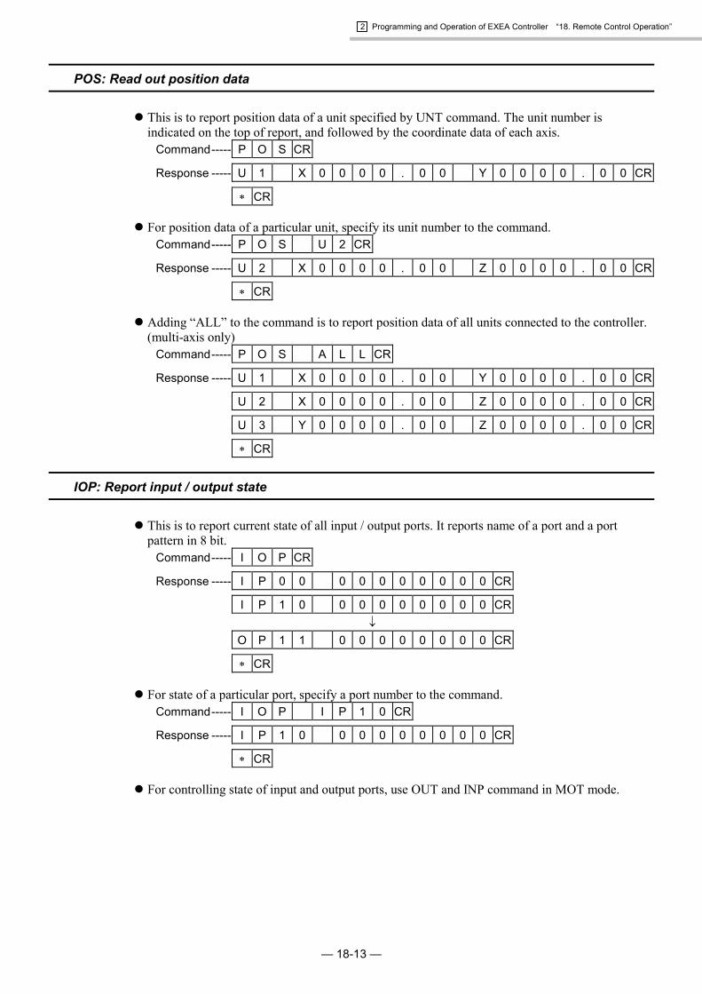
2 Programming and Operation of EXEA Controller “18. Remote Control Operation”
— 18-13 —
POS: Read out position data
� This is to report position data of a unit specified by UNT command. The unit number isindicated on the top of report, and followed by the coordinate data of each axis.
Command----- P O S CR
Response ----- U 1 X 0 0 0 0 . 0 0 Y 0 0 0 0 . 0 0 CR
� CR
� For position data of a particular unit, specify its unit number to the command.Command----- P O S U 2 CR
Response ----- U 2 X 0 0 0 0 . 0 0 Z 0 0 0 0 . 0 0 CR
� CR
� Adding “ALL” to the command is to report position data of all units connected to the controller.(multi-axis only)
Command----- P O S A L L CR
Response ----- U 1 X 0 0 0 0 . 0 0 Y 0 0 0 0 . 0 0 CR
U 2 X 0 0 0 0 . 0 0 Z 0 0 0 0 . 0 0 CR
U 3 Y 0 0 0 0 . 0 0 Z 0 0 0 0 . 0 0 CR
� CR
IOP: Report input / output state
� This is to report current state of all input / output ports. It reports name of a port and a portpattern in 8 bit.
Command----- I O P CR
Response ----- I P 0 0 0 0 0 0 0 0 0 0 CR
I P 1 0 0 0 0 0 0 0 0 0 CR�
O P 1 1 0 0 0 0 0 0 0 0 CR
� CR
� For state of a particular port, specify a port number to the command.Command----- I O P I P 1 0 CR
Response ----- I P 1 0 0 0 0 0 0 0 0 0 CR
� CR
� For controlling state of input and output ports, use OUT and INP command in MOT mode.

2 Programming and Operation of EXEA Controller “18. Remote Control Operation”
— 18-14 —
UNT: Specify motion unit number [Multi-axis]
� This is to specify a motion unit number.Command----- U N T U 2 CR
Response ----- � CR
� If the only UNT command is inputted, it outputs a unit number currently selected.Command----- U N T CR
Response ----- U 2 CR
� CR
� If none of unit is specified by the command U1 is valid as the initial setting.

2 Programming and Operation of EXEA Controller “18. Remote Control Operation”
— 18-15 —
18.4.2.2. Mode Declaration Command
QUIT: Withdrawal of mode declaration command
� Withdraw a current declaration of the command mode. This command cannot be carried outwhile executing the remote control operation or programmed operation. Declaration of the modewill be withdrawn after execution of these operations.
Command (1) - A B C CR � Declared command mode
Response (1)-- A B C > � CR
Command (2) - Q U I T CR � Withdrawal of declaration
Response (2)-- � CR
MOT: Remote control operation mode
� This is to specify an operation mode that controls directly the operations such as Home return ora linear interpolation. Switching mode by this command is invalid during execution of theremote control operation in any manner.
Command----- M O T CR
Response ----- M O T > � CR
RUN: Programmed operation mode
� This is to specify a mode to start a programmed operation stored in the EXEA controllermemory.
Command----- R U N CR
Response ----- R U N > � CR
� This command is invalid while the other programmed operation is executed.
TCH: Teaching mode
� This is to specify a mode to edit coordinate data.Command----- T C H CR
Response ----- T C H > � CR
EDT: Program editing mode
� This is to specify a mode to edit program.Command----- E D T CR
Response ----- E D T > � CR

2 Programming and Operation of EXEA Controller “18. Remote Control Operation”
— 18-16 —
PAL: Palletizing editing mode [Multi-axis]
� Specifies a mode to edit palletizing.Command----- P A L CR
Response ----- P A L > � CR
SYS: Parameter editing mode
� This is to specify a mode to initialize parameters (editing parameters).Command----- S Y S CR
Response ----- S Y S > � CR
CTR: Controller setting mode
� Specifies a mode to set function of the controller.Command----- C T R CR
Response ----- C T R > � CR
FNC: Special function operating mode
� This is to specify a mode to operate special function of the controller.Command----- F N C CR
Response ----- F N C > � CR

2 Programming and Operation of EXEA Controller “18. Remote Control Operation”
— 18-17 —
18.4.2.3. MOT Mode • Second Level Command
� Refer to “15.2.7.3. Program Command” for details of each commands.
MOT mode SPD: Set motion speed and acceleration / deceleration
� Specifies the interpolation speed, acceleration and deceleration for a motion unit currentlyspecified by UNT command. Unit number can be omitted when its speed, acceleration anddeceleration are unchanged. Execution of the command, which is attempted during the specifiedunit is in motion, is not valid until its next motion command.(Unit name is omissible as the unit number is always “1” for a single axis system.)
Command----- S P D S 1 0 0 A 1 0 B 1 0 CR
Response ----- M O T > � CR
� Add a particular unit number to the command when changing its speed.(multi-axis combination only)
Command----- S P D U 2 S 1 0 0 A 1 0 CR
Response ----- M O T > � CR
MOT mode TYP: Set motion format
� This is to specify the motion format of a motion unit specified by UNT command. When thecommand is input during an objective unit is in motion, the command is invalid till it is ready forthe next start.(Unit name is omissible as the unit number is always “1” for a single axis system.)
Command----- T Y P & A T F P E L CR
Response ----- M O T > � CR
� When changing the motion format of a particular unit, add its unit number to the command.(multi-axis combination only)
Command----- T Y P U 2 & A T F P E L CR
Response ----- M O T > � CR
MOT mode NOF: Set off-set value of point register
� This is to specify off-set number of point register of a motion unit currently selected by UNTcommand. When the command is inputted during the unit is in motion, it is invalid until the unitstarts the next motion.(Unit name is omissible as the unit number is always “1” for a single axis system.)
Command----- N O F # 1 0 0 CR
Response ----- M O T > � CR
� When changing off-set value of a particular unit, add its unit number to the command.(multi-axis combination only)
Command----- N O F U 2 # 1 0 0 CR
Response ----- M O T > � CR

2 Programming and Operation of EXEA Controller “18. Remote Control Operation”
— 18-18 —
MOT mode PBS: Setting working reference point
� Specifies the working reference point of a currently specified motion unit by UNT. When theobjective unit is in motion, the command is invalid until it starts the next operation.(Unit name is omissible as the unit number is always “1” for a single axis system.)
Command 1 -- P B S P 0 0 0 0 CR � Specify point register
Command 2 -- P B S X 0 0 0 0 . 0 0 Y 0 0 0 0 . 0 0
CR� Specify coordinate data directly
Response ----- M O T > � CR
� When changing the setting of the working reference point of a particular unit, add its unitnumber to the command. (multi-axis combination only)
Command----- P B S U 2 P 0 0 0 0 CR
Response ----- M O T > � CR
MOT mode ESCZ: Set off-limits area of Z axis [Multi-axis]
� This is to specify upper and lower off-limits boundary and turnout position of Z axis of a motionunit currently specified by UNT command. When the command is input during the unit is inmotion, it is invalid until the unit starts the next motion.
Command (1) - E S C Z P X 0 0 0 0 P Y 0 0 0 0 P Z
0 0 0 0 CR� Specify point register.* This is an example of setting upper and lower off-limits boundary and turnout
position of point number 0000 by X, Y and Z axes coordinates.
Command (2) - E S C Z 0 0 0 0 . 0 0 0 1 0 0 . 0 0
0 1 2 5 . 0 0 CR� Specify coordinates data directly.* This is an example of setting off-limits area in order of upper, lower boundary
and turnout position by coordinate data directly.
Response ------ M O T > � CR
� When specifying off-limits area of a particular unit, add its unit number to the command.Command----- E S C Z U 2 0 0 0 0 . 0 0 0 1 0 0 .
0 0 0 1 2 5 . 0 0 CR � Specify coordinates data directly.
Response ----- M O T > � CR

2 Programming and Operation of EXEA Controller “18. Remote Control Operation”
— 18-19 —
MOT mode SRV: Switch servo on / off
� Switches servo on and off of the designated axis of motion unit currently specified by UNTcommand.However, to make it works, the controller must be in the “permitting servo on” state by SVONcommand.The command works only in MOT mode.
Command----- S R V Designate axis CR
Response ----- M O T > � CR
* Designate axis ---- Specify servo on (1) or servo off (0) of each axis unit such as “X1 Y1 Z1” or“X0 Y0 Z0.”Default axis unit does not change its state of servo.
Command----- S R V X 1 CR
Response ----- M O T > � CR
� To specify a particular motion unit, add its number to the command.Command----- S R V U 1 Designated axis CR
� Change state of servo of unit 1.Response ----- M O T > � CR
� Add ON or OFF to the command to switch the servo state of all units that are connected to thecontroller.
Command----- S R V O N CR � Servo on all units
S R V O F F CR � Servo off all units
Response ----- M O T > � CR

2 Programming and Operation of EXEA Controller “18. Remote Control Operation”
— 18-20 —
MOT mode HOM: Start home return
� Starts Home return of a motion unit currently specified by UNT command. When the systemenables to start Home return normally, the prompt changes from “�” to “#.” The prompt changesto “�” again when Home return is completed.(Unit name is omissible as the unit number is always “1” for a single axis system.)
Command----- H O M CR
Response ----- M O T > # CR � Executing home return.
M O T > � CR � Home return complete.
� To start Home return of a particular motion unit, add its unit number to the command.(multi-axis combination only)
Command----- H O M U 2 CR
Response ----- M O T > # CR
� Add a particular axis number to the command to start its Home return. You may omit unit number.(multi-axis combination only)
Command----- H O M U 2 X CR
Response ----- M O T > # CR
� Add “ALL” to the command to start Home return of all units that are connected to the controller.You can not specify a particular axis to this command. (multi-axis combination only)
Command----- H O M A L L CR
Response ----- M O T > # CR

2 Programming and Operation of EXEA Controller “18. Remote Control Operation”
— 18-21 —
MOT mode MOV: Start linear interpolation * *(In a single axis system this is regarded as linear motion.)
� Starts linear interpolation of motion unit currently specified by UNT command. When thesystem enables to start the linear interpolation normally, the prompt changes from “�” to “#.” Ifthe linear interpolation is completed, the prompt returns to “�” again.
Command----- M O V P 0 0 0 1 CR
Response ----- M O T > # CR � Executing linear interpolation.
M O T > � CR � Complete linear interpolation.
� To start linear interpolation of a particular motion unit, add its unit number to the command.Command----- M O V U 2 P 0 0 0 1 CR
Response ----- M O T > # CR
� It is possible to specify coordinate values of each point directly instead of inputting the pointregister. Input the data for operating axis only.
Command----- M O V X 0 0 0 0 . 0 0 Y 0 0 0 0 . 0 0
CR
Response ----- M O T > # CR
� It is possible to specify speed, acceleration, deceleration and motion format. However, thesesettings are valid for this command only, but not for other operation.
Command----- M O V P 0 0 0 1 S 6 0 0 CR
Response ----- M O T > # CR
MOT mode MOVM: Start continuous linear interpolation * (multi-point)* This is regarded as continuous linear motion (multi-point) in a single axis system.
� Starts continuous linear interpolation of motion unit currently specified by UNT command.When the continuous linear interpolation starts normally, the prompt changes from “�” to “#.”When the continuous linear interpolation is completed, the prompt returns to “�” again.
Command----- M O V M P 0 0 0 1 P 0 0 1 1 CR
Response ----- M O T > # CR � Executing continuous linear interpolation.
M O T > � CR � Complete continuous linear interpolation.
� To start continuous linear interpolation of a particular motion unit, add its unit number to thecommand. (multi-axis combination only)
Command----- M O V M U 2 P 0 0 0 1 P 0 0 1 1 CR
Response ----- M O T > # CR
� It is possible to specify speed, acceleration, deceleration and motion format. However, thesesettings are valid for this command only, but not for other operation.
Command----- M O V M P 0 0 0 1 P 0 0 1 1 S 6 0
0 CR
Response ----- M O T > # CR

2 Programming and Operation of EXEA Controller “18. Remote Control Operation”
— 18-22 —
MOT mode ARC: Start circular arc interpolation [Multi-axis]
� Starts circular arc interpolation of a motion unit currently specified by UNT command. Whenthe arc interpolation starts normally, the prompt changes from “�” to “#.” As the arcinterpolation is completed, the prompt returns to “�” again.
Command----- A R C P 0 0 0 1 P 0 0 0 2 P 0 0 0 3
CR
Response ----- M O T > # CR � Executing arc interpolation.
M O T > � CR � Complete of arc interpolation.
� To start an arc interpolation of a particular motion unit, add its unit number to the command.Command----- A R C U 2 P 0 0 0 1 P 0 0 0 2 P 0
0 0 3 CR
Response ----- M O T > # CR
� It is possible to specify speed, acceleration, deceleration and motion format. However, thesesettings are valid for this command only, not valid for other operation.
Command----- A R C P 0 0 0 1 P 0 0 0 2 P 0 0 0 3
S 6 0 0 CR
Response ----- M O T > # CR
MOT mode CIR: Start circular interpolation [Multi-axis]
� Starts a circular interpolation of motion unit currently specified by UNT command. When thecircular motion starts normally, the prompt changes from “�” to “#.” As the circular motion iscompleted, the prompt returns to “�” again.
Command----- C I R P 0 0 0 1 P 0 0 0 2 P 0 0 0 3
CR
Response ----- M O T > # CR � Executing circular motion.
M O T > � CR � Complete of circular motion.
� To start a circular motion of a particular motion unit, add its unit number to the command.Command----- C I R U 2 P 0 0 0 1 P 0 0 0 2 P 0
0 0 3 CR
Response ----- M O T > # CR
� It is possible to specify speed, acceleration, deceleration and motion format. However, thesesettings are valid for this command only, but not for other operation.
Command----- C I R P 0 0 0 1 P 0 0 0 2 P 0 0 0 3
S 6 0 0 CR
Response ----- M O T > # CR

2 Programming and Operation of EXEA Controller “18. Remote Control Operation”
— 18-23 —
MOT mode MSTP: Motion stop
� Decelerates and stops motion of motion unit currently specified by UNT command. The prompt“#” is outputted when decelerating and returns to prompt “�” after the unit stops. This commandis meaningless when the motion unit is not moving. (It does not lead to an alarm.)(Unit name is omissible as the unit number is always “1” for a single axis system.)
Command----- M S T P CR
Response ----- M O T > # CR � Decelerating the motion unit.
M O T > � CR � Stopped.
� To stop motion of a particular motion unit, add its unit number to the command.(multi-axis combination only)
Command----- M S T P U 2 CR
Response ----- M O T > # CR
� When stopping a particular axis unit, add its axis name. The unit number can be a default.(multi-axis combination only)
Command----- M S T P U 2 X CR
Response ----- M O T > # CR
� Add “ALL” to the command to stop all motion units connected to the controller. In this case,you cannot specify an axis. (multi-axis combination only)
Command----- M S T P A L L CR
Response ----- M O T > # CR
MOT mode MSPD: Reserved (cannot use)
MOT mode MSTS: Read out motion state
� This is to substitute the motion state of a motion unit currently specified by UNT command to adata register. (Unit name is omissible as the unit number is always “1” for a single axis system.)
Command----- M S T S D 0 0 0 CR
Response ----- M O T > � CR
� When substituting the motion state of specified unit to a data register, specify an objective unitname as shown below. (multi-axis combination only)
Command----- M S T S D 0 0 0 = U 2 CR
Response ----- M O T > � CR
� Motion state number to be substituted has meaning as shown below. 0 ---------------Stopping
1 --------------- In motion

2 Programming and Operation of EXEA Controller “18. Remote Control Operation”
— 18-24 —
MOT mode PALI: Initialize palletizing operation [Multi-axis]
� This is to correlate the palletizing operation number (QN00) and the pallet data number to enablea palletizing operation of a motion unit currently specified by UNT command.
Command----- P A L I Q N 0 0 # 0 0 CR
Response ----- M O T > � CR
� You may specify a name of pallet data instead of a palletizing operation number.Command----- P A L I Q N 0 0 $ P A L N A M E CR
Response ----- M O T > � CR
� For execution to initialize palletizing operation of a particular motion unit, specify its unitnumber to the command.
Command----- P A L I U 2 Q N 0 0 # 0 0 CR
Response ----- M O T > � CR
� It is possible to specify a motion format. However, only &A and &I are valid. These areeffective to this command only, but not for other motions.
Command----- P A L I U 2 Q N 0 0 # 0 0 & A CR
Response ----- M O T > # CR
MOT mode PALM: Palletizing operation: positioning [Multi-axis]
� This is to start the motion of designated palletizing operation number to a pallet position. Whenoperation starts normally, the prompt changes from “�” to “#.” As the operation is completed,the prompt returns to “�” again and reset the palletizing operation counter.
Command----- P A L M Q N 0 0 CR
Response ----- M O T > # CR � Palletizing in motion.
M O T > � CR � Palletizing completed.
� Specify a pallet position number with QP××× when moving to a particular pallet position.Command----- P A L M Q N 0 0 Q P 0 0 0 CR
Response ----- M O T > # CR
� It is possible to specify speed, acceleration / deceleration and motion format. However, thosesettings are effective to this command only, but not for other operation.
Command----- P A L M Q N 0 0 S 6 0 0 CR
Response ----- M O T > # CR

2 Programming and Operation of EXEA Controller “18. Remote Control Operation”
— 18-25 —
MOT mode PALN: Palletizing operation; change positioning number [Multi-axis]
� Changes the setting of palletizing positioning counter of a specified palletizing operation number.Normally a palletizing sequential operation is performed by PALM command. This PALNcommand is to change the sequential order of the operations. When the command is inputtedwhile the palletizing operation of a designated palletizing operation number is executed, it is noteffective until the next PALM command is on.
Command----- P A L N Q N 0 0 # 2 2 CR
Response ----- M O T > � CR
MOT mode QSTS: Palletizing operation: read out the palletizing state [Multi-axis]
� This command is to substitute a state of palletizing (number of palletizing points) of a specifiedpalletizing operation number to a data register.
Command----- Q S T S D 0 0 0 = Q N 0 0 Q P M CR
Response ----- M O T > � CR
� Substitute a state of palletizing (point number of the next palletizing) of a specified palletizingoperation to a data register.
Command----- Q S T S D 0 0 0 = Q N 0 0 Q P C CR
Response ----- M O T > � CR
* The output of point number is normally in the range of 0 (zero) to (QPM - 1). However the outputis “ -1 (minus)” if all palletizing operation have completed.
� Substitute coordinates data of palletizing point of a specified palletizing operation number to apoint register.
Command----- Q S T S P 0 0 0 0 = Q N 0 0 Q P 0
0 0 CR
Response ----- M O T > � CR

2 Programming and Operation of EXEA Controller “18. Remote Control Operation”
— 18-26 —
MOT mode LDS: Read out, system setting state
� This is to output the state of system setting (offset value of point number) of a unit currentlyspecified by UNT command then, substitute it for a designated variables (data register or pointregister). As the variable is shared with the programmed operation, you must be very carefulwhen execute the command simultaneously with the programmed operation.(Unit name is omissible as the unit number is always “1” for a single axis system.)
Command 1 -- L D S D 0 0 0 = N O F CR
Command 2 -- L D S P 0 0 0 0 = P B S CR
Response ----- M O T > � CR
� To read out system setting state of a particular unit, specify its unit number to the command.(multi-axis combination only)
Command----- L D S D 0 0 0 = U 1 N O F CR
Response ----- M O T > � CR
� Changing a code of the command enables to read out the state of motion setting.
1) Data to be substituted to a specified data register.N O F � Offset value of point number
S P D � Speed (numerical number) setting
S P D R � Setting of motion speed (percentage reading)
A C C � Acceleration (numerical number) setting
A C C R � Acceleration (percentage reading) setting
D A C � Deceleration (numeric reading) setting
D A C R � Deceleration (percentage reading)
2) Data to be substituted to a specified point register.P B S � Setting of working reference point
3) Data to be substituted to a specified axis in a point register.(multi-axis combination only)
E S C Z U P R � Off-limits area of Z axis (upper boundary)
E S C Z L W R � Off-limits area of Z axis (lower boundary)
E S C Z P O S � Off-limits area of Z axis (turnout position)
MOT mode LD: Substitute data
� This is to substitute numerical value or contents of point register for a designated variable. Asthe variable is shared with programmed operation, you must be very cautious to execute thiscommand simultaneously with programmed operation.
Command 1 -- L D D 0 0 0 = D 0 0 0 CR
Command 2 -- L D P 0 0 0 0 = X 0 0 0 0 . 0 0 Y
0 0 0 0 . 0 0 CR
Response ----- M O T > � CR

2 Programming and Operation of EXEA Controller “18. Remote Control Operation”
— 18-27 —
MOT mode CAL: Calculate data
� This is to execute calculations of numerals or each content between data registers and tosubstitute the results for the designated variables (data or point register). As the variables areshared with programmed operation, you must be very careful when execute this commandsimultaneously with the programmed operation.
Command----- C A L D 0 0 0 = D 0 0 0 + # 1 0
0 CR
C A L D 0 0 0 = D 0 0 0 – # 1 0
0 CR
Response ----- M O T > � CR
� If the results are unable to substitute for the variables, an alarm will be given.Command----- C A L D 0 0 0 = D 0 0 0 + # 1 0
0 CR
Response ----- ! F 5 CR � Alarm code
M O T > � CR
� The following code for calculation are available.+ � Addition
– � Subtraction
� � Multiplication
/ � Division
% � Percentage
MOT mode TCH: Substitute current coordinate data for specified variable
� This is to substitute the current position data of a unit currently specified by UNT command forthe specified variable. As the variables are shared with programmed operation, be careful whenexecute this command simultaneously with the programmed operation.
Command----- T C H P 0 0 0 0 = X 1 Y 0 CR
Response ----- M O T > � CR
� For reading out current position of a particular unit, specify its unit number to the command.(multi-axis combination only)
Command----- T C H P 0 0 0 0 = U 1 X 1 Y 0 CR
Response ----- M O T > � CR

2 Programming and Operation of EXEA Controller “18. Remote Control Operation”
— 18-28 —
MOT mode OUT: Set output port
� Sets the state of specified output port.Command 1 -- O U T O P 0 0 = ; 0 0 0 1 0 1 1 0 CR
Command 2 -- O U T O P 1 1 = D 0 0 0 CR
Command 3 -- O U T O B 1 0 1 = O N CR
Response ----- M O T > � CR
� When specifying by bit, the following code are available. (command 3 above)O N � Output is on.
O F F � Output is off.
R E V � Reverse the output.
MOT mode INP: Get input port state
� Gets the state of specified input port to a data register.Command----- I N P D 0 0 0 = I P 1 0 CR
Response ----- M O T > � CR
MOT mode LCAL: Execute logical operation of data
� This is to execute logical operation of numerical data or contents between data registers then, tosubstitute results for the specified variables. As the variables are shared with the programmedoperation, be careful when executing this command simultaneously with the programmedoperation.
Command----- L C A L D 0 0 0 = D 0 0 0 O R D
0 0 1 CR
Response ----- M O T > � CR
� If the results are unable to substitute for the designated variables, an alarm will be given.Command----- L C A L D 0 0 0 = D 0 0 0 O R D
0 0 1 CR
Response ----- ! F 5 CR � Alarm code
M O T > � CR
� The following code to indicate the way of logical operation are available.O R � Logical addition
A N D � Logical multiplication
X O R � Exclusive OR

2 Programming and Operation of EXEA Controller “18. Remote Control Operation”
— 18-29 —
MOT mode DAT: Read out state of variable
� Read out the contents of a specified variable.Command 1 -- D A T D 0 0 1 CR
Response 1--- D 0 0 1 1 2 3 . 0 0 CR
M O T > � CR
Command 2 -- D A T P 0 0 0 1 CR
Response 2--- P 0 0 0 1 X 0 0 0 0 . 0 0 Y 0 0 0 0 .
0 0 CR
M O T > � CR
� You can specify the reading range by adding ( - ) (dash) to data numbers.Command----- D A T D 0 0 1 – D 0 0 3 . 0 0 CR
Response ----- D 0 0 1 1 2 3 . 0 0 CR
D 0 0 2 – 2 2 0 0 . 0 0 CR
D 0 0 3 1 0 0 . 0 0 CR
M O T > � CR

2 Programming and Operation of EXEA Controller “18. Remote Control Operation”
— 18-30 —
18.4.2.4. RUN Mode • Second Level Command
RUN mode LST: Read out program data
� This is to read out program data for confirmation. For details, refer to LST command in EDTmode. When you need to confirm all program data of the desired program number, the followingshows how to do it.
Command----- L S T 0 0 CR
Response ----- 0 0 / N A M $ P R G N A M E CR
0 0 / M E M U S E R _ P R O G _ M E M O CR
0 0 / S T E 3 1 9 CR
0 0 / 0 0 0 M O V P 0 0 0 1 CR
0 0 / 0 0 1 M O V P 0 0 0 2 CR�
0 0 / 3 1 9 E N D CR
R U N > � CR

2 Programming and Operation of EXEA Controller “18. Remote Control Operation”
— 18-31 —
RUN mode STA: Start programmed operation
1 Programmed operation
� This command is effective when “RUN mode” of the parameter related to set PMD is set to“PRG” (programmed operation).
� This is to start a programmed operation specified by a program number or name of program.When the operation has started normally, the prompt changes to “#” from “�”.
Command ---- S T A 0 0 CR � Specify program number
S T A $ P R G N A M E CR � Specify name of program.
Response----- R U N > # CR
� If you require a step operation, put “S” to the end of command.Command ---- S T A 0 0 S CR
Response----- R U N > $ CR
� When resuming a program which has been on hold state, input “R” instead of program number.Possibility of resuming the programmed operation can be checked by “Output status ofprogrammed operation” command (STS command).
Command ---- S T A R CR � Resume programmed operation.
Response----- R U N > # CR
� For restart the operation in “cycle stop state” or “hold state” (when the prompt is $), input simply“STA” command. An error alarm arises when a step operation command is inputted to resumethe operation in cycle stop or hold state.
Command ---- S T A CR
Response----- R U N > # CR
2 Direct operation
� The command is effective when “RUN mode” of the parameter related to set PMD is set to“POS” (direct operation).
� In “directly inputted coordinate operation”, the command starts a motion to a position ofdesignated point register. When the motion is successful, the prompt changes to “# ” from “�”.
Command ---- S T A 0 0 0 0 CR � Designate a number.
Response----- R U N > # CR
You may specify quantity of units which can be operated simultaneously.
Command ---- S T A 0 0 0 0 0 0 CR � Designate a number.
Response----- R U N > # CR

2 Programming and Operation of EXEA Controller “18. Remote Control Operation”
— 18-32 —
RUN mode STP: Stop programmed operation
� This is to terminate programmed operation. When the operation has stopped, the prompt returnsto “�”.
Command ---- S T P CR
Response----- R U N > � CR
� The prompt # is output first when it takes time to decelerate and stop completely because themotor has been running at the moment of the command is input. The prompt returns to “�” afterthe motor stops completely.
Command ---- S T P CR
Response----- R U N > # CR � Decelerating.
R U N > � CR � Stop operation completed.
� If the programmed operation is not executed at the moment of inputting the command (when theprompt is �), an error message will be responded.
Command----- S T P CR
Response ----- ? 0 2 0 7 CR
R U N > � CR
RUN mode CSTP: Cycle stop, programmed operation
� This is to execute cycle stop of a programmed operation. The prompt changes to “$” as thesystem gets in “cycle stop state.”
Command----- C S T P CR
Response ----- R U N > $ CR
� When the motor requires time for deceleration and complete stop, as it’s been moving, firstly theprompt changes to “ # ” then the prompt changes to “$” as the motor stops completely.
Command----- C S T P CR
Response ----- R U N > # CR � Decelerating.
R U N > $ CR � Cycle stop completed.
� If the programmed operation is not executed at the moment of inputting the command (when theprompt is �), an error message will be responded.
Command----- C S T P CR
Response ----- ? 0 2 0 7 CR
R U N > � CR
* CSTP command is effective in hold stop state as well.

2 Programming and Operation of EXEA Controller “18. Remote Control Operation”
— 18-33 —
RUN mode HLD: Hold programmed operation
� Execute hold stop. The prompt is “$” when the hold stop state is established.Command----- H L D CR
Response ----- R U N > $ CR
� When the motor requires time for deceleration as it’s been moving, the prompt “# ” is returned,then the prompt changes to “ $ ” as the motor stops completely.
Command----- H L D CR
Response ----- R U N > # CR � Decelerating.
R U N > $ CR � Hold stop completed.
� If a programmed operation is not executed at the moment of inputting the command (whenprompt is “*”.), an error message will be responded.
Command----- H L D CR
Response ----- ? 0 2 0 7 CR
R U N > � CR
* HLD command is not effective in cycle stop state.
RUN mode STS: Read out state of programmed operation
� Indicates current state of a programmed operation.Command----- S T S CR
Response ----- R A CR � In operation (in continuous operation).
R U N > # CR
� The states indicated in operation are listed below.
1) RA: In operation (continuous operation)
2) RS: In operation (step operation)
3) CA: Stopping by cycle stop (continuous operation)
4) CS: Stopping by cycle stop (step operation)
5) HA: Stopping by hold (continuous operation)
6) HS: Stopping by hold (step operation)
7) SE: Ceased operation (possible to resume.)
8) SD: Ceased operation (impossible to resume)

2 Programming and Operation of EXEA Controller “18. Remote Control Operation”
— 18-34 —
� Add letter S or C to the command if you require the details of operation state. Output data for “S”comprise sequence stage, program number and step number, while output data for “C” include thecontents of command in addition to the output items for “S”.
Command ---- S T S S CR
Response----- M 0 0 2 / 0 0 1 CR
R U N > # CR
Command ---- S T S C CR
Response----- M 0 0 2 / 0 0 1 M O V P 0 0 3 CR
R U N > # CR
� Three letters of M, S and C are used to indicate stage of sequence. Each letter corresponds to thestage as shown below.
M: Main programS : Sub-sequence (executing simultaneous operation command)C : Secondary sequence
� As STS command indicates all operating sequence, the display will be as shown below when the programis operated in multitask mode (in case of multi axis combination). Be careful as number of lines differaccording to operation state.
Command ---- S T S C CR
Response----- M 0 0 2 / 0 2 1 T I M 0 0 ~ CR (1)
S 0 0 2 / 0 0 3 M O V P 0 ~ CR (2)
C 0 1 2 / 1 0 2 L D P 0 3 ~ CR (3)
S 0 1 2 / 1 0 0 M O V P 0 ~ CR (4)
C 0 1 4 / 0 3 2 T I M 0 0 ~ CR (5)
R U N > # CR
� Above example shows that (1) and (2) are main programs, (3) and (4) are secondary sequence 1,and (5) as secondary sequence 2. A sub sequence indicated by “S” is for a main or secondarysequence previously reported.
� Letters S and C are invalid for direct operation. However you may add “P” instead. Output data for “P”are the point number and number of units.
Command ---- S T S P CR
Response----- M 0 0 0 2 / 1 CR
R U N > # CR
* Operating data is 1 when indication of number of unit is “0”, while operating data is 2 whenindication of unit is 1. Indication of number is fixed to “0” for a single axis system.
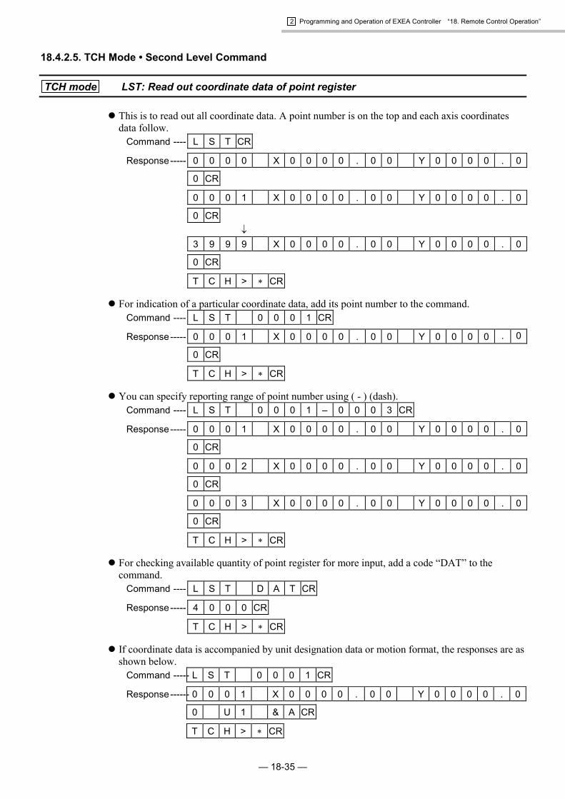
2 Programming and Operation of EXEA Controller “18. Remote Control Operation”
— 18-35 —
18.4.2.5. TCH Mode • Second Level Command
TCH mode LST: Read out coordinate data of point register
� This is to read out all coordinate data. A point number is on the top and each axis coordinatesdata follow.
Command ---- L S T CR
Response----- 0 0 0 0 X 0 0 0 0 . 0 0 Y 0 0 0 0 . 0
0 CR
0 0 0 1 X 0 0 0 0 . 0 0 Y 0 0 0 0 . 0
0 CR�
3 9 9 9 X 0 0 0 0 . 0 0 Y 0 0 0 0 . 0
0 CR
T C H > � CR
� For indication of a particular coordinate data, add its point number to the command.Command ---- L S T 0 0 0 1 CR
Response----- 0 0 0 1 X 0 0 0 0 . 0 0 Y 0 0 0 0 . 0
0 CR
T C H > � CR
� You can specify reporting range of point number using ( - ) (dash).Command ---- L S T 0 0 0 1 – 0 0 0 3 CR
Response----- 0 0 0 1 X 0 0 0 0 . 0 0 Y 0 0 0 0 . 0
0 CR
0 0 0 2 X 0 0 0 0 . 0 0 Y 0 0 0 0 . 0
0 CR
0 0 0 3 X 0 0 0 0 . 0 0 Y 0 0 0 0 . 0
0 CR
T C H > � CR
� For checking available quantity of point register for more input, add a code “DAT” to thecommand.
Command ---- L S T D A T CR
Response----- 4 0 0 0 CR
T C H > � CR
� If coordinate data is accompanied by unit designation data or motion format, the responses are asshown below.
Command ----- L S T 0 0 0 1 CR
Response------ 0 0 0 1 X 0 0 0 0 . 0 0 Y 0 0 0 0 . 0
0 U 1 & A CR
T C H > � CR

2 Programming and Operation of EXEA Controller “18. Remote Control Operation”
— 18-36 —
TCH mode SET: Set coordinate data of point register
� This is to set coordinate data of a point register. The command changes only the data setting of aspecified coordinate axis, but not for an unspecified coordinate axis. (Set X axis coordinate onlyfor a single axis system.)
Command ---- S E T 0 0 9 9 X 0 0 0 0 . 0 0 Y 0 0
0 0 . 0 0 CR
Response----- T C H > � CR
� Add the letter C to a name of axis to indicate “non-motion” (does not move) coordinate data.Command ---- S E T 0 0 9 9 X C Y 0 0 0 0 . 0 0 CR
Response----- T C H > � CR
� Add the letter T to a coordinate axis for setting its current position to a point register. When aparticular unit is specified, its current position coordinate data are set. If no particular unit isspecified, the current position coordinates data of a specified motion unit by UNT command areregistered.
Command ---- S E T 0 0 9 9 X T Y 0 0 0 0 . 0 0 CR
Response----- T C H > � CR
� To specify a motion unit, add its unit number to the end of coordinate data, or declare only itsunit number.
Command 1 -- S E T 0 0 9 9 X 0 0 0 0 . 0 0 Y 0 0
0 0 . 0 0 U 1 CR
Response 1 -- T C H > � CR
Command 2 -- S E T 0 0 9 9 U 1 CR
Response 2 -- T C H > � CR
� Input C instead of unit number to cancel specifying motion unit.Command ---- S E T 0 0 9 9 U C CR
Response----- T C H > � CR
� Add a format code to end of coordinate data, or declare only a motion format to specify. Only A(absolute coordinates) and I (relative coordinates) are effective as a motion format.
Command 1 -- S E T 0 0 9 9 X 0 0 0 0 . 0 0 Y 0 0
0 0 . 0 0 & A CR
Response 1 -- T C H > � CR
Command 2 -- S E T 0 0 9 9 & A CR
Response 2 -- T C H > � CR
� To cancel to specify a motion format , input C to a part of format code.Command ---- S E T 0 0 9 9 & C CR
Response----- T C H > � CR

2 Programming and Operation of EXEA Controller “18. Remote Control Operation”
— 18-37 —
TCH mode CLR: Initialize coordinate data
� Initializes all coordinate data and sets all coordinate axes to “non-motion” data.Command ---- C L R CR
Response----- T C H > � CR
� To initialize only one coordinate data, specify its point number to the command.Command ---- C L R 0 0 9 9 CR
Response----- T C H > � CR
� You may set the range of initializing point numbers using a ( - ) (dash).Command ---- C L R 0 0 9 9 – 0 1 2 0 CR
� Point register: Number 99 to 120 are the objectives for initialization.Response----- T C H > � CR
TCH mode CPY: Copy coordinate data
� This is to copy a coordinate data of a point number (left) to the designated point number (right).Command ---- C P Y 0 0 0 9 0 0 1 2 CR
� Copy coordinate data of point number 9 topoint number 12.
Response----- T C H > � CR
� You can specify the range of point register numbers as the copy source using ( - ) (dash). Whenthe copied data range is more than the specified copy area, only the data that can be copiedwithin the specified area will be stored.
Command ---- C P Y 0 0 0 9 – 0 0 1 2 0 0 2 2 CR � Copy coordinate data of point number 9 to 12 to
point number 22 to 25.Response----- T C H > � CR
TCH mode SAV: Store edited data
� This is to store all edited data not to lose due to the power shut down.Command ---- S A V CR
Response----- T C H > � CR
Caution : When data save is completed, the prompt mark (�) is returned. Do not shutdown the power while saving data. Otherwise it leads to a memory erroralarm and all data must be initialized for recovery.
TCH mode LOD: Cancel edited data
� This is to cancel all edited data to return to the original state just after the data was saved lasttime. If the coordinate data, such as the data set for programmed operation, are not stored, allcontents of settings will be lost.
Command ---- L O D CR
Response----- T C H > � CR

2 Programming and Operation of EXEA Controller “18. Remote Control Operation”
— 18-38 —
18.4.2.6. EDT Mode • Second Level Command
EDT mode LST: Read out program data
� This is to report all program data of the specified program number. The output reports the data inthe order of name of program, user memo, total number of steps and step data.
Command ---- L S T 0 0 CR
Response----- 0 0 0 / N A M $ P R G N A M E CR
0 0 0 / M E M U S E R _ P R O G _ M E M
O CR
0 0 0 / S T E 3 1 9 CR
0 0 0 / 0 0 0 M O V P 0 0 0 1 CR
0 0 0 / 0 0 1 M O V P 0 0 0 2 CR�
0 0 0 / 3 1 9 E N D CR
E D T > � CR
� To output data of a particular line, add a code or step number after the program number.Command 1 -- L S T 0 0 / N A M CR � Program name.
Response 1 -- 0 0 0 / N A M $ P R G N A M E CR
E D T > � CR
Command 2 -- L S T 0 0 / M E M CR � Indication of user memo.
Response 2 -- 0 0 0 / M E M U S E R _ P R O G _ M E M
O CR
E D T > � CR
Command 3 -- L S T 0 0 / S T E CR � Total number of steps.
Response 3 -- 0 0 0 / S T E 3 1 9 CR
E D T > � CR
Command 4 -- L S T 0 0 / 0 0 1 CR � Data of specified step.
Response 4 -- 0 0 0 / 0 0 1 M O V P 0 0 0 1 CR
E D T > � CR
� You may input the name of program, instead of the program number, to identify the program.Command ---- L S T $ P R G N A M E CR � Name of program.
Response----- 0 3 9 / N A M $ P R G N A M E CR�
0 3 9 / 3 1 9 E N D CR
E D T > � CR

2 Programming and Operation of EXEA Controller “18. Remote Control Operation”
— 18-39 —
� Input “ALL” instead of the program number to report all program data.Command ---- L S T A L L CR
Response----- 0 0 0 / N A M $ P R G N A M E CR�
0 9 9 / 0 9 9 E N D CR
E D T > � CR
� You may specify the range of step number using ( - ) (dash).Command ---- L S T 0 0 0 / 0 0 1 – 0 0 3 CR
Response----- 0 0 0 / 0 0 1 M O V P 0 0 0 3 CR
0 0 0 / 0 0 2 M O V P 0 0 0 4 CR
0 0 0 / 0 0 3 M O V P 0 0 0 5 CR
E D T > � CR
� Add “DAT” to the command to confirm available room for storing more programs. The outputindicates the allowable number of programs and steps in the program.
Command ---- L S T D A T CR
Response----- 1 2 8 / 1 0 0 0 CR
E D T > � CR
EDT mode SET: Register program data
� Specify a program number and a step number for registration of the program data.Command ---- S E T 0 0 / 0 9 9 M O V P 0 0 0 3 CR
Response----- E D T > � CR
� When setting a program data to the end step, input “END” instead of step number.Command ---- S E T 0 0 1 / E N D M O V P 0 0 0 3 CR
Response----- E D T > � CR
� When setting the name of program, input a code “NAM” instead of step number.Command ---- S E T 0 0 1 / N A M $ P R G N A M E CR
Response----- E D T > � CR
� When setting the user memo, input a code “MEM” instead of step number.Command ---- S E T 0 0 1 / M E M U S E R _ M E M O CR
Response----- E D T > � CR
� When the name of the program has been set, it is possible to use the name instead of the programnumber to identify the program.
Command ---- S E T $ P R G N A M E / 0 9 9 M O V P
0 0 0 3 CR
Response----- E D T > � CR

2 Programming and Operation of EXEA Controller “18. Remote Control Operation”
— 18-40 —
EDT mode CLR: Initialize program data
� This is to initialize all program data and user memo.Command ---- C L R CR
Response----- E D T > � CR
� Add the program number to specify the program.Command ---- C L R 0 1 CR
Response----- E D T > � CR
� When the name of program has been registered, you may use it to identify the program.Command ---- C L R $ P R G N A M E CR
Response----- E D T > � CR
EDT mode DEL: Delete program data
� This is to delete the program data of the specified program number and step number. The rest ofprogram steps move up one step.
Command ---- D E L 0 0 3 / 0 0 9 CR
Response----- E D T > � CR
� You may specify the range of numbers to be deleted using ( - ) (dash). The rest of steps move upto the positions of deleted ones.
Command ---- D E L 0 0 3 / 0 0 9 – 0 1 2 CR � Delete step 9 to 12.
Response----- E D T > � CR
� When the name of the program has been registered, you may use it to identify the program.Command ---- D E L $ P R G N A M E / 0 0 9 CR
Response----- E D T > � CR
EDT mode INS: Insert program data
� This is to insert a blank step to the specified step of the specified program. The step to where ablank step is inserted will move down one step.
Command ---- I N S 0 0 3 / 0 0 9 CR
Response----- E D T > � CR
� When the name of program has been registered, you may use it to identify the program.Command ---- I N S $ P R G N A M E / 0 0 9 CR
Response----- E D T > � CR
� When inserting multiple blank steps, add a desired quantity to the end of the step number.Command ---- I N S 0 0 3 / 0 0 9 0 5 CR
Response----- E D T > � CR

2 Programming and Operation of EXEA Controller “18. Remote Control Operation”
— 18-41 —
EDT mode CPY: Copy program data
� This is to copy a program data of a specified step number (left) to a specified step number (right).If the copying step number is bigger than the last step, the step data will be put behind it.
Command ---- C P Y 0 0 3 / 0 0 1 0 0 3 / 0 0 9 CR � Copy step 1 to step 9.
Response----- E D T > � CR
� You may specify the range of step numbers to be copied using ( - ) (dash).Command ---- C P Y 0 0 3 / 0 0 9 – 0 1 2 0 0 3 / 0
2 2 CR � Copy steps 9 to 12 to 22 and over.
Response----- E D T > � CR
� When the name of program has been registered, you may use it to specify the program number.Command ---- C P Y $ P R G N A M E / 0 0 1 0 3 / 0
0 9 CR
Response----- E D T > � CR
EDT mode SAV: Save edited program data
� This is to save all edited program data to prevent from losing due to power shut down.Command ---- S A V CR
Response----- E D T > � CR
Caution : The prompt mark (�) is returned when the data saving is completed. Do notshut down the power while saving data. Otherwise it leads to a memoryerror alarm and all data must be initialized for recovery.
EDT mode LOD: Delete edited data
� Delete all edited program data to return to the original state just after the data was saved lasttime.
Command ---- L O D CR
Response----- E D T > � CR
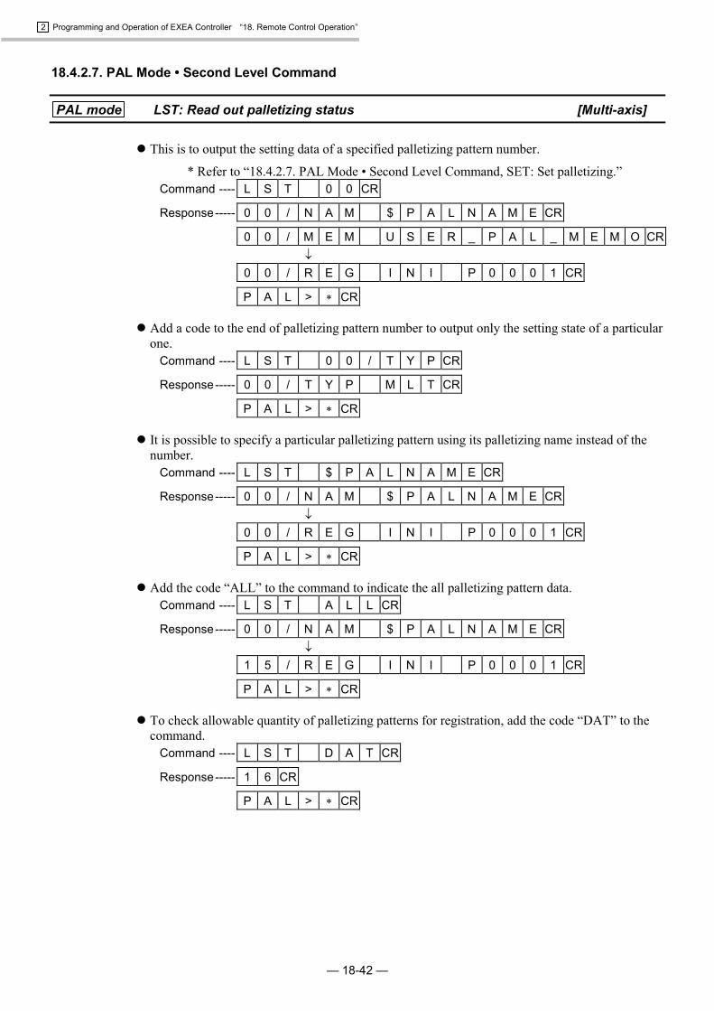
2 Programming and Operation of EXEA Controller “18. Remote Control Operation”
— 18-42 —
18.4.2.7. PAL Mode • Second Level Command
PAL mode LST: Read out palletizing status [Multi-axis]
� This is to output the setting data of a specified palletizing pattern number.
* Refer to “18.4.2.7. PAL Mode • Second Level Command, SET: Set palletizing.”Command ---- L S T 0 0 CR
Response----- 0 0 / N A M $ P A L N A M E CR
0 0 / M E M U S E R _ P A L _ M E M O CR�
0 0 / R E G I N I P 0 0 0 1 CR
P A L > � CR
� Add a code to the end of palletizing pattern number to output only the setting state of a particularone.
Command ---- L S T 0 0 / T Y P CR
Response----- 0 0 / T Y P M L T CR
P A L > � CR
� It is possible to specify a particular palletizing pattern using its palletizing name instead of thenumber.
Command ---- L S T $ P A L N A M E CR
Response----- 0 0 / N A M $ P A L N A M E CR�
0 0 / R E G I N I P 0 0 0 1 CR
P A L > � CR
� Add the code “ALL” to the command to indicate the all palletizing pattern data.Command ---- L S T A L L CR
Response----- 0 0 / N A M $ P A L N A M E CR�
1 5 / R E G I N I P 0 0 0 1 CR
P A L > � CR
� To check allowable quantity of palletizing patterns for registration, add the code “DAT” to thecommand.
Command ---- L S T D A T CR
Response----- 1 6 CR
P A L > � CR

2 Programming and Operation of EXEA Controller “18. Remote Control Operation”
— 18-43 —
PAL mode SET: Set palletizing pattern data [Multi-axis]
� This is to specify a palletizing pattern number and codes, then to register its program data. Add acode “NAM” to the command to set a name of palletizing pattern.
Command ---- S E T 0 1 / N A M $ P A L N A M E CR
Response----- P A L > � CR
� Add “MEM” to the command to put user memo to it.Command ---- S E T 0 1 / M E M U S E R _ M E M O CR
Response----- P A L > � CR
� If the name of palletizing pattern is registered, specify it instead of the number to identify aparticular palletizing pattern.
Command ---- S E T $ P A L N A M E / S P S ~ CR
Response----- P A L > � CR
� The following show the codes and data format for setting palletizing pattern data.(1) NAM -----Sets name of palletizing pattern
N A M $ P A L N A M E
(2) MEM-----Sets user memo.M E M U S E R _ M E M O
(3) TYP ------Sets pallet positioning format.T Y P M L T � Multiple regular interval format.
T Y P D I V � Divided sides format.
T Y P P N T � Three corners format.
(4) AXS------Change operating axis unit [normally two axes (X and Y) operation]A X S X X Y Y
� Two axes palletizing (X and Y axis units operation)
(5) SPS------Set starting point.
(6) WDT -----Sets palletizing position interval.
(7) XPS------Sets corner point X.
(8) YPS------Sets corner point Y.S P S P 0 0 0 1
S P S X 0 0 0 0 . 0 0 Y 0 0 0 0 . 0 0
(9) NUM -----Sets number of position intervals / number of steps.N U M P 0 0 0 1
N U M X 0 0 Y 0 0
(10) PTN ----Sets moving direction.P T N X N R M � X axis unit takes precedence. Moves to one direction.
P T N X R E V � X axis unit takes precedence. Moves in both direction.
P T N Y N R M � Y axis unit takes precedence. Moves to one direction.
P T N Y R E V � Y axis unit takes precedence. Moves in both direction.
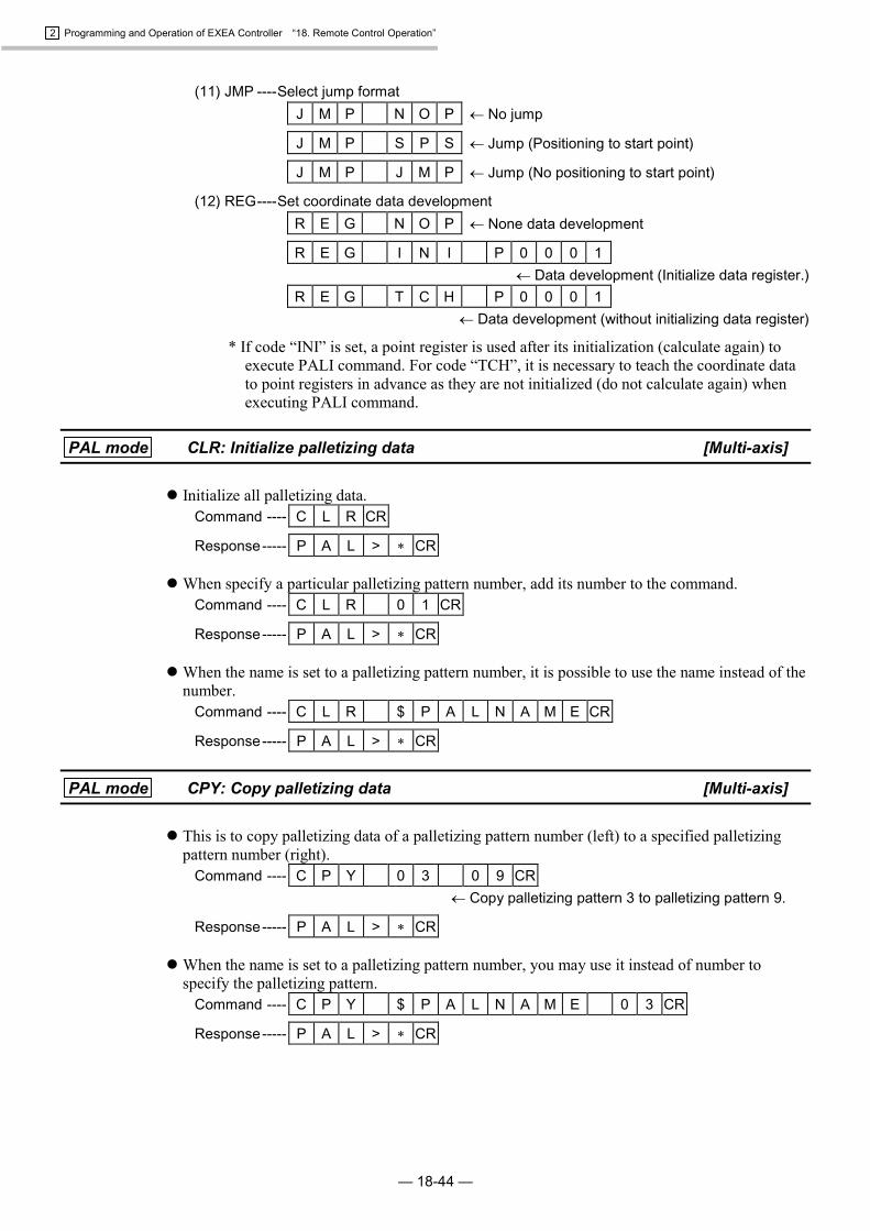
2 Programming and Operation of EXEA Controller “18. Remote Control Operation”
— 18-44 —
(11) JMP ----Select jump formatJ M P N O P � No jump
J M P S P S � Jump (Positioning to start point)
J M P J M P � Jump (No positioning to start point)
(12) REG----Set coordinate data developmentR E G N O P � None data development
R E G I N I P 0 0 0 1� Data development (Initialize data register.)
R E G T C H P 0 0 0 1 � Data development (without initializing data register)
* If code “INI” is set, a point register is used after its initialization (calculate again) toexecute PALI command. For code “TCH”, it is necessary to teach the coordinate datato point registers in advance as they are not initialized (do not calculate again) whenexecuting PALI command.
PAL mode CLR: Initialize palletizing data [Multi-axis]
� Initialize all palletizing data.Command ---- C L R CR
Response----- P A L > � CR
� When specify a particular palletizing pattern number, add its number to the command.Command ---- C L R 0 1 CR
Response----- P A L > � CR
� When the name is set to a palletizing pattern number, it is possible to use the name instead of thenumber.
Command ---- C L R $ P A L N A M E CR
Response----- P A L > � CR
PAL mode CPY: Copy palletizing data [Multi-axis]
� This is to copy palletizing data of a palletizing pattern number (left) to a specified palletizingpattern number (right).
Command ---- C P Y 0 3 0 9 CR � Copy palletizing pattern 3 to palletizing pattern 9.
Response----- P A L > � CR
� When the name is set to a palletizing pattern number, you may use it instead of number tospecify the palletizing pattern.
Command ---- C P Y $ P A L N A M E 0 3 CR
Response----- P A L > � CR

2 Programming and Operation of EXEA Controller “18. Remote Control Operation”
— 18-45 —
PAL mode TCH: Develop palletizing data to point register [Multi-axis]
� Develops all palletizing data to point registers. However, this is only valid when the setting ofREG parameters is INI or TCH.
Command ---- T C H CR
Response----- P A L > � CR
� To specify a palletizing data, add its palletizing pattern number to the command.Command ---- T C H 0 1 CR
Response----- P A L > � CR
� If the name is set to the palletizing pattern number, you may use it instead of the number foridentification.
Command ---- T C H $ P A L N A M E CR
Response----- P A L > � CR
� When a palletizing pattern, which is not set to develop palletizing data to a point register, isspecified (when REG parameter is NOP), TCH command is meaningless.
PAL mode SAV: Save edited data [Multi-axis]
� This is to save all edited data not to lose them due to power shut down.Command ---- S A V CR
Response----- P A L > � CR
Caution : The prompt mark (�) responds when the data saving is completed. Duringsaving data, do not turn the power off. Otherwise, it leads to a memory erroralarm and all data must be initialized for recovery.
PAL mode LOD: Cancel edited data [Multi-axis]
� This is to cancel all edited contents to return to the state just after the power is turned on.Command ---- L O D CR
Response----- P A L > � CR

2 Programming and Operation of EXEA Controller “18. Remote Control Operation”
— 18-46 —
18.4.2.8. SYS Mode • Second Level Command
SYS mode LST: Report parameter setting
� This command is to report parameter setting of a motion unit currently specified by UNTcommand.
Command ---- L S T CR
Response----- U 1 / L S P 0 6 0 0 . 0 CR
U 1 / L A C 0 0 . 5 CR�
U 1 / C O X 3 0 0 0 0 Y 3 0 0 0 0 CR
S Y S > � CR
� To check a particular parameter setting, add its code to the command.Command ---- L S T L A C CR
Response----- U 1 / L A C 0 0 . 5 CR
S Y S > � CR
� For checking parameter setting of a particular motion unit, specify its unit number.(multi-axis combination only)
Command ---- L S T U 2 CR
Response----- U 2 / L S P 0 6 0 0 . 0 CR�
U 2 / C O X 3 0 0 0 0 Y 3 0 0 0 0 CR
S Y S > � CR
� It is possible to specify a unit number and a code simultaneously. (multi-axis combination only)Command ---- L S T U 2 / L A C CR
Response----- U 2 / L A C 0 0 . 5 CR
S Y S > � CR
� For reporting all parameters of all units, add the code “ALL” to the command.(multi-axis combination only)
Command ---- L S T A L L CR
Response----- U 1 / L S P 0 6 0 0 . 0 CR
U 1 / L A C 0 0 . 5 CR�
U 4 / C O X 3 0 0 0 0 Y 3 0 0 0 0 CR
S Y S > � CR

2 Programming and Operation of EXEA Controller “18. Remote Control Operation”
— 18-47 —
SYS mode SET: Set parameter
� This is to set parameters of a motion unit currently specified by UNT command. The parametersin this setting are the same as the parameters described in “9. Initial Setting.” Please refer toChapter 10. Table 18-4 below shows the parameters described in Chapter 10 and their codesused in this setting.(Unit name is omissible as the unit number is always “1” for a single axis system.)
Table 18-4Initializingparameter Code Set to respective
units.Initializingparameter Code Set to respective
units.Locus speed LSP Escape (pos.Z) EPZLocus accel LAC Escape (upr.R) EUR *Max speed MSP � Escape (lwr.R) ELR *Max accel MAC � Escape (pos.R) EPR *Finish width MFW � Payload LO �
Finish mode MFM Servo Gain SG * �
Fin control FCT Feedfoward Gain FF �
Fin out time FTI Torque Limit TL �
Home speed HSP Dead Band DB �
Home accel HAC Low Pass Filter 1 FP �
Home search speed HSS Low Pass Filter 2 FS �
Home direction HDR � Notch Filter NP �
Home sequence HSQ � Gain Mode – * �
Home shift HSF � Position Loop Gain PG �
Home move HMV � Velocity Loop Gain VG �
Home move mode HMM Observer Gain DO �
Home unit seq. HUS Observer Limit DOL �
Jog speed (H) JSH Notch Filter Q1 NPQ �
Jog speed (L) JSL Position Direction PD �
Jog accel JAC Hard. OT Timer HOT �
Overtravel (+) OTP � Rated Current RC �
Overtravel (-) OTM � Over Load OL �
Escape (upr.Z) EUZ Position Error Over CO �
Escape (lwr.Z) ELZ Note: There are several parameters which shall be set toan axis unit respectively. It is indicated in thecolumn of “Set to respective units.”
* Reserved: do not set
� For the parameters those are set to each axis units respectively, an axis unit shall be specified tochange their setting. Command. The command 1 below is an example that X and Y axis units arespecified for a change, while the command 2 specifies Y axis unit only. Only X axis unit shall bespecified for a single axis system.
Command 1 -- S E T H S F X 0 0 0 0 . 0 0 Y 0 0 0
0 . 0 0 CR
Command 2 -- S E T H S F Y 0 0 0 0 . 0 0 CR
Response----- S Y S > � CR
� When changing a parameter of a particular motion unit, specify the unit number in front of aparameter code.
Command ---- S E T U 1 / H S F Y 0 0 0 0 . 0 0 CR
Response----- S Y S > � CR

2 Programming and Operation of EXEA Controller “18. Remote Control Operation”
— 18-48 —
SYS mode CLR: Initialize parameter
� This is to initialize the parameters for system setting of all motion units.Command ---- C L R CR
Response----- S Y S > � CR
� When initializing parameters of a particular motion unit only, add its unit number to thecommand.
Command ---- C L R U 1 CR
Response----- S Y S > � CR
SYS mode SAV: Store edited parameter
� This is to store the edited parameters not to lose due to the power shut down.Command ---- S A V CR
Response----- S Y S > � CR
Caution : The prompt mark (�) responds when saving parameter is completed. Do notturn off the power during parameter saving. Otherwise it leads to memoryerror alarm and you must initialize all parameters for recovery.
SYS mode LOD: Cancel edited parameter
� Cancel all edited parameters to return to the state just after the power is turned on.Command ---- L O D CR
Response----- S Y S > � CR

2 Programming and Operation of EXEA Controller “18. Remote Control Operation”
— 18-49 —
18.4.2.9. CTR Mode • Second Level Command
CTR mode LST: Report setting in controller
� This is to report the module main unit setting of a motion unit currently specified by UNTcommand.(Unit name is omissible as the unit number is always “1” for a single axis system.)
Command ---- L S T CR
Response----- U 1 / T Y P O F F CR
U 1 / M D X X Y – H R S 0 5 0 – P H 2 0
0 1 X CR�
U 1 / M D R CR
C T R > � CR
� To have indications of a particular setting, add its code to the command.Command ---- L S T M D X CR
Response----- U 1 / M D X X Y – H R S 0 5 0 – P H 2 0
0 1 X CR
C T R > � CR
� To have the setting state of a particular motion unit, add the unit number to the command.(multi-axis combination only)
Command ---- L S T U 2 CR
Response----- U 2 / T Y P O F F CR�
U 2 / M D R X Y – H R S 0 2 0 – P M 2 0
0 4 R CR
C T R > � CR
� It is possible to specify both unit number and the code simultaneously.(multi-axis combination only)
Command ---- L S T U 2 / T Y P CR
Response----- U 2 / T Y P O F F CR
C T R > � CR

2 Programming and Operation of EXEA Controller “18. Remote Control Operation”
— 18-50 —
� To indicate the settings of all parameters, add the code “ALL” to the command.Command ---- L S T A L L CR
Response----- U 1 / T Y P O F F CR
U 1 / M D X X Y – H R S 0 5 0 – P H 2 0
0 1 X CR�
U 4 / M D R X Y – H R S 0 2 0 – P M 2 0
0 4 R CR
U S R 1 L 1 0 R 4 0 9 6 N R M W 1
0 0 CR�
U S R 8 L 1 0 R 4 0 9 6 N R M W 1
0 0 CR
E M S T N O P CR�
R U N P R G CR
I B 0 0 0 E M S T B CR�
I B 1 1 7 U S E R A CR
O B 0 0 0 R D Y B CR�
O B 1 1 7 U S E R A CR
C T R > � CR
� To indicate the settings of parameters of all units, add the code “UNT” to the command.(multi-axis combination only)
Command ---- L S T U N T CR
Response----- U 1 / T Y P O F F CR
U 1 / M D X X Y – H R S 0 5 0 – P H 2 0
0 1 X CR�
U 4 / M D R X Y – H R S 0 2 0 – P M 2 0
0 4 R CR
C T R > � CR

2 Programming and Operation of EXEA Controller “18. Remote Control Operation”
— 18-51 —
� To have the settings of all user modules, add the code “USR” to the command.Command ---- L S T U S R CR
Response----- U S R 1 L 1 0 R 4 0 9 6 N R M W 1
0 0 CR�
U S R 8 L 1 0 R 4 0 9 6 N R M W 1
0 0 CR
C T R > � CR
� To have the settings of a particular user module setting, add the code “USR�” to the command.(� is a number of user module.)
Command ---- L S T U S R 1 CR
Response----- U S R 1 L 1 0 R 4 0 9 6 N R M W 1
0 0 CR
C T R > � CR
� To indicate only Input / Output setting state, add the “IOP” to the command.Command ---- L S T I O P CR
Response----- E M S T N O P CR�
R U N P R O G CR
I B 0 0 0 E M S T B CR�
I B 1 1 7 U S E R A CR
O B 0 0 0 R D Y A CR�
O B 1 1 7 U S E R A CR
C T R > � CR
� To indicate only state of a particular Input / Output setting, add the “EMST” or “IB000” to thecommand.
Command ---- L S T I B 0 0 0 CR
Response----- I B 0 0 0 E M S T B CR
C T R > � CR

2 Programming and Operation of EXEA Controller “18. Remote Control Operation”
— 18-52 —
CTR mode SET: Specify controller setting
� This is to set the type of a module main unit to a motion unit which is currently specified by“UNT” command. Declare the code of module type or data to be set. The parameters to be sethere are the same as the parameters that are described in “9. Initial Setting.” Refer to Chapter 9as well.(Unit name is omissible as the unit number is always “1” for a single axis system.)
Command ---- S E T T Y P O F F CR
Response----- C T R > � CR
� To set a type of module main unit of a particular motion unit, add its unit number in front of thecode. You cannot specify a unit number for settings of user unit or input / output.
Command ---- S E T U 1 / T Y P O F F CR
Response----- C T R > � CR
� The following show the code and data format used for setting a type of module main unit.
(1) TYP ------Setting of module combination number: Set to OFF.(The same setting as factory set)
T Y P O F F
(2) MDX -----Setting X axis module main unit
(3) MDY -----Setting Y axis module main unit
(4) MDZ -----Setting Z axis module main unit
(5) MDR -----Setting R axis module main unit
Multi-axis combination only.
M D X X Y – H R S 0 5 0 – P H 2 0 0 1
X
* Specify module main unit reference number, connected power amplifier number andname of axis.
Caution : Make sure to set the axis units to be used. Incorrect setting leads tomalfunction of the robot.
� Specifying “OFF” to a setting of main unit type will reset to the factory set.M D X O F F 1 X
� If only “C” is specified to main unit type setting, the axis unit will be a “none-motion” axis. Inthis case, an indication by the command LST does not report the parameters as shown below.
Command ---- L S T M D X CR
Response----- U 1 / M D X CR (multi-axis combination only)
C T R > � CR

2 Programming and Operation of EXEA Controller “18. Remote Control Operation”
— 18-53 —
* If the same amplifier number is set to multiple axis units, or the same axis name is assigned todifferent axes in the one unit, the precedence is given in the order of (X � R) axes.
U1/MDX OFF 1 X ----- Unit 1 X axis (Amplifier 1)
U1/MDY OFF 2 Y ----- Unit 1 Y axis (Amplifier 2)
U1/MDZ OFF 3 X ----- Invalid
U1/MDR
U2/MDX OFF 1 X ----- Invalid
U2/MDY OFF 4 Y ----- Unit 2, Y axis (Amplifier 4)
U2/MDZ
U2/MDR
� The code and data format used to set user module are shown below. Adding a unit number touser module is meaningless.
(1) USER1--User module 1
(2) USER2--User module 2�
(3) USER8--User module 8Multi-axis combination only.
U S R 1 L 1 0 R 4 0 9 6 N R M W 1
0 0
* Specify ball screw lead, encoder resolution, motor mounting and motor power.
� The code and data format used in Input / Output setting are shown below. Adding unit number tothis setting is meaningless.
(1) EMST ---Operation data saving mode at Emergency stop: Do not set other than NOP (factory set).
(2) STOP----Operation data saving mode at Stop: Do not set other than NOP (factory set).
(3) CSTP----Operation data saving mode at cycle stop: Do not set other than NOP (factory set).
(4) ALARM--Operation data saving mode at alarm stop: Do not set other than NOP (factory set).
E M S T N O P
(5) RUN -----Format of operation start command.R U N P R G
(6) IB000 ----Set state of input port 000.�
IB117----Set state of input port 117.OB000 --Set state of output port 000.�
OB117 --Set state of output port 117.I B 0 0 0 E M S T B
* Specify state of the port usage and state of signal contact (open or close).
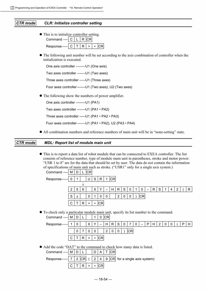
2 Programming and Operation of EXEA Controller “18. Remote Control Operation”
— 18-54 —
CTR mode CLR: Initialize controller setting
� This is to initialize controller setting.Command ---- C L R CR
Response----- C T R > � CR
� The following unit number will be set according to the axis combination of controller when theinitialization is executed.
One axis controller --------U1 (One axis)
Two axes controller -------U1 (Two axes)
Three axes controller -----U1 (Three axes)
Four axes controller -------U1 (Two axes), U2 (Two axes)
� The following show the numbers of power amplifier.
One axis controller --------U1 (PA1)
Two axes controller -------U1 (PA1 • PA2)
Three axes controller -----U1 (PA1 • PA2 • PA3)
Four axes controller -------U1 (PA1 • PA2), U2 (PA3 • PA4)
� All combination numbers and reference numbers of main unit will be in “none-setting” state.
CTR mode MDL: Report list of module main unit
� This is to report a data list of robot module that can be connected to EXEA controller. The listconsists of reference number, type of module main unit in parentheses, stroke and motor power.“USR 1 to 8” are for the data that should be set by user. The data do not contain the informationof specifications of main unit such as stroke. (“USR1” only for a single axis system.)
Command ---- M D L CR
Response----- 0 1 U S R 1 CR�
2 5 6 X Y – H R S 0 1 0 – R S 1 4 2 ( R
S z 0 1 0 0 2 0 0 ) CR
C T R > � CR
� To check only a particular module main unit, specify its list number to the command.Command ---- M D L 1 0 CR
Response----- 1 0 X Y – H R S 0 7 0 – P H 2 0 0 ( P H
0 7 0 0 2 0 0 ) CR
C T R > � CR
� Add the code “DAT” to the command to check how many data is listed.Command ---- M D L D A T CR
Response----- 7 2 CR ( 2 4 9 CR for a single axis system)
C T R > � CR
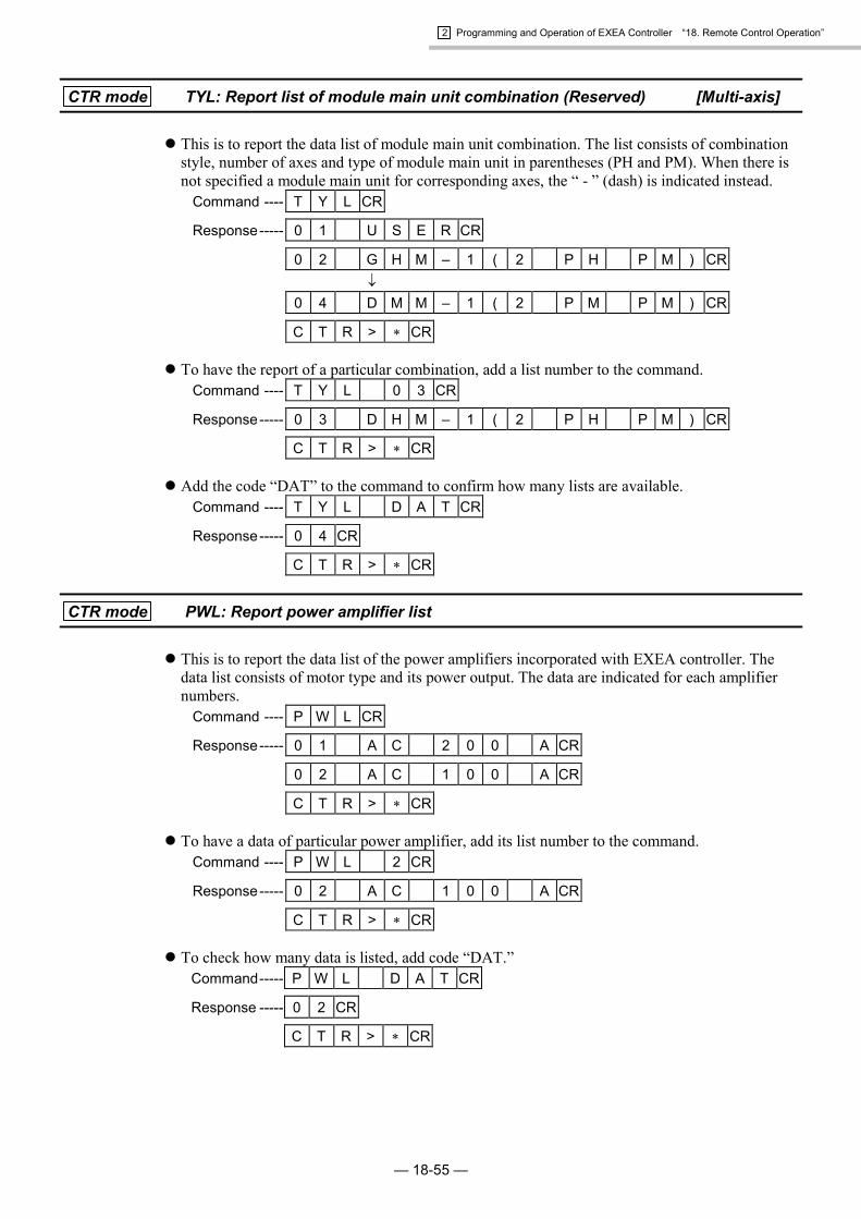
2 Programming and Operation of EXEA Controller “18. Remote Control Operation”
— 18-55 —
CTR mode TYL: Report list of module main unit combination (Reserved) [Multi-axis]
� This is to report the data list of module main unit combination. The list consists of combinationstyle, number of axes and type of module main unit in parentheses (PH and PM). When there isnot specified a module main unit for corresponding axes, the “ - ” (dash) is indicated instead.
Command ---- T Y L CR
Response----- 0 1 U S E R CR
0 2 G H M – 1 ( 2 P H P M ) CR�
0 4 D M M – 1 ( 2 P M P M ) CR
C T R > � CR
� To have the report of a particular combination, add a list number to the command.Command ---- T Y L 0 3 CR
Response----- 0 3 D H M – 1 ( 2 P H P M ) CR
C T R > � CR
� Add the code “DAT” to the command to confirm how many lists are available.Command ---- T Y L D A T CR
Response----- 0 4 CR
C T R > � CR
CTR mode PWL: Report power amplifier list
� This is to report the data list of the power amplifiers incorporated with EXEA controller. Thedata list consists of motor type and its power output. The data are indicated for each amplifiernumbers.
Command ---- P W L CR
Response----- 0 1 A C 2 0 0 A CR
0 2 A C 1 0 0 A CR
C T R > � CR
� To have a data of particular power amplifier, add its list number to the command.Command ---- P W L 2 CR
Response----- 0 2 A C 1 0 0 A CR
C T R > � CR
� To check how many data is listed, add code “DAT.”Command----- P W L D A T CR
Response ----- 0 2 CR
C T R > � CR

2 Programming and Operation of EXEA Controller “18. Remote Control Operation”
— 18-56 —
CTR mode SAV: Save edited data
� This is to store all edited data not to lose them due to unexpected power shut down.Command ---- S A V CR
Response----- C T R > � CR
Caution : When saving data completes the prompt (�) is returned. Do not shut off thepower while saving the data. Otherwise it leads to a memory error and theall data must be initialized for recovery.
CTR mode LOD: Cancel edited data
� Cancels all edited data to get back to the state just after the power is tuned on.Command ---- L O D CR
Response----- C T R > � CR

2 Programming and Operation of EXEA Controller “18. Remote Control Operation”
— 18-57 —
18.4.2.10. FNC Mode • Second Level Command
FUN mode INI: Initialize controller
� Reset the controller to the factory set. All stored data will be deleted.Command ---- I N I CR
Response----- F N C > � CR

2 Programming and Operation of EXEA Controller “18. Remote Control Operation”
— 18-58 —
(Blank Page)

NSK-RHP FRANCE S.A.FRANCE : Paris Phone:1.30.57.39.39
: Lyon Phone: 72.15.29.00
NSK-RHP NEDERLAND B.V.NETHERLAND: Amsterdam Phone: 020-6470711
NSK-RHP ITALIA S.p.A.ITALIA: Milano Phone: 02-995191
NSK-RHP IBERICA, S.A.SPAIN: Barcelona Phone: 93-575-1662
NSK-RHP AUSTRALIA PTY, LTD.AUSTRALIA : Melbourne Phone: 03-9764-8302
: Sydney Phone: 02-9893-8322: Brisbane Phone: 07-3393-1388: Adelaide Phone: 08-8373-4811: Perth Phone: 089-434-1311
NSK-RHP BEARINGS NEW ZEALAND LTD.NEW ZEALAND: Auckland Phone: 09-276-4992
NSK KOREA CO., LTD.KOREA: Seoul Phone: 02-3287-6001
NSK SINGAPORE (PRIVATE) LTD.SINGAPORE: Singapore Phone: 2781711
NSK BEARINGS (THAILAND) CO., LTD.THAILAND : Bangkok Phone: 2-6412150-60
: Chiang mai Phone: 053-246993~4
TAIWAN NSK PRECISION CO., LTD.TAIWAN: Taipei Phone: 02-591-0656
NSK Ltd. INTERNATIONAL DIVISIONJAPAN: Tokyo Phone: 03-3779-7120
NSK CORPORATIONU.S.A.: Ann Arbor Phone: 313-761-9500
[Precision Products Business Unit]U.S.A. : Chicago Phone: 630-924-8000
: Los Angeles Phone: 562-926-3578: Ann Arbor Phone: 761-761-9500
NSK•RHP CANADA INC.CANADA : Toront Phone: 905-890-0740
: Montreal Phone: 514-633-1240: Vancouver Phone: 800-663-5445
NSK RODAMIENTOS MEXICANA, S.A. DE C.V.MEXICO: Mexico City Phone: 5-301-2741,5-301-3115
NSK DO BRASIL INDUSTRIA E COMÉRCIO DEROLAMENTOS LTDA.BRASIL : São Paulo Phone: 001-269-4700
: Porto Alegre Phone: 051-222-1324: Belo Horizonte Phone: 031-224-2508
NSK-RHP UK LTDENGLAND : Ruddington Phone: 0115-936-6600
NSK-RHP DEUTSCHLAND G.m.b.HGERMANY : Düsseldorf Phone: 02102-4810
: Stuttgart Phone: 0711-79082-0: Leipzig Phone: 0341-5631241
World-wide Manufacturing and Marketing Organization
Robot Module System� P Series Module Main Unit� R Series Module Main Unit� EXEA ControllerUser’s Manual 2= Programming and Operation of EXEA Controller =Document Number: K20079-01 EC-T
August 3, 2000 1st Edition 1st Printing
NSK Ltd.

1st Edition, 1st Printing August 3, 2000 Document Number: K20079-01


![UNITED STATES COURT OF INTERNATIONAL TRADE NSK LTD., NSK ...public].pdf Plaintiffs and Defendant-Intervenors NSK Ltd., NSK Corp., NSK Precision America, Inc. Barnes, ... covering a](https://img.dokumen.tips/doc/110x75/5c4aa13793f3c34c55086977/united-states-court-of-international-trade-nsk-ltd-nsk-publicpdf-plaintiffs.jpg)