Embed Size (px)
Citation preview

ROADS V6.3
Reference Manual
Copyright 2004
KNOWLEDGE BASE

Conditions of Sale
The purchaser (further referred to as the Licensee) hereby accepts a non-exclusive, non-transferable license to use the software, Civil Designer, on the following conditions.
1. The license fee shall be payable in advance and this agreement commences on said date of purchase.
2. A separate license fee is payable for each CPU upon which the Licensee wishes to use the software.
3. The Licensee undertakes not to copy, except for backup purposes, reproduce, translate, adapt, vary or modify the software, nor to communicate the software to any third party other than the Licensee’s employees, without the Licensor’s prior written consent.
4. The Licensee agrees that it shall not itself or through any subsidiary, agent or third party, sell, lease, license, sub-license or otherwise deal with the software.
5. The Licensee acknowledges that any and all of the intellectual property rights including trademark, trade name, copyright and other rights used or embodied in or in connection with the software shall be and remain the sole property of the Licensor and it’s principals.
6. The Licensee shall not question or dispute the ownership of any such rights at any time.
7. It is up to the Licensee to insure the program for the full replacement value. In the event of theft or loss of the program, security disk, or security module the license must be re-purchased in full.
8. No warranty of any kind is made with regard to the use or application of the software or it’s fitness for any particular purpose. The verification of all results and output is entirely the responsibility of the purchaser.
9. While every care has been taken in the preparation of the Civil Designer program and it’s manual, Knowledge Base cc, it’s employees and agents shall not be liable for any loss or damage (including in particular, consequential losses, loss of profits and penalties) suffered by the Licensee arising from any cause whatsoever in connection with the Civil Designer program or the use thereof whether such loss or damage results from breach of contract (including a fundamental breach), negligence or any other cause and whether or not this contract is at any time cancelled by the Licensee arising from any cause whatsoever in connection with the Civil Designer program or the use thereof whether or not this contract is at any time cancelled.


Table of Contents
WELCOME Where do I go from here? 1-1
Typefaces in this manual 1-2 Conventions used in this manual 1-2 How to get support 1-3 On-line help 1-3 Online documentation 1-4
BASIC THEORY Conventions 2-2
TUTORIAL - ROADS DESIGN Select the working road 3-2 Input the horizontal alignment 3-4 Changing the alignment 3-5 Review and coordinate 3-5
Extract cross-sections 3-8 Vertical alignment 3-9 Define a road template 3-12 Compulsory additions 3-13 Cut and fill conditions 3-14 Specify a Pavement design 3-15 Preview 3-16 Template Number 3-18
Calculate the road levels 3-19 Calculate the road levels 3-19 Calculate the cross section areas 3-21 Calculate the volumes 3-22 Calculating Layerwork volumes 3-22 Create a cross-section drawing 3-24
Create a long section drawing 3-26 Create a site plan 3-29
FILE MENU New Project 4-2 Drawing File 4-3 Terrain File 4-3 Sewer File 4-4 Storm File 4-4 Locale 4-4
Open Project 4-7 Edit Project 4-8 Save Project 4-9 Save Project As 4-9 Close Project 4-9 Select Road File 4-10 Import 4-12 ASCII Cross Sections 4-12 Cards Cross Sections 4-15 Long Section 4-18 R?? File 4-20 Ceaser Design 4-22
Export 4-23 Cross Sections 4-23 Long Section 4-24 Ceaser Survey 4-25 Export MX Roads (Moss) 4-25
Output Manager 4-27 Spool Output 4-29 Option Settings 4-30 General 4-31 Survey 4-34 Terrain 4-35 Roads 4-39 Plot 4-42 Output Window 4-43
Security 4-44 Authorize 4-44 Check Network Dongles 4-45
Exit 4-45
SECTIONS MENU Graphical Edit 5-2 Insert Point 5-4 Edit Point 5-5 Delete Point 5-6 Move Point 5-7 Polygon Area 5-8 Line Intersection 5-9 Goto Chainage 5-10 Layer Details 5-11 List Sections 5-12 Enter/Edit Sections 5-13 Interpolate 5-15 Remove Points 5-18
Remove Points 5-18 Transfer Points 5-21 Absolute Change 5-24 Expand/Shrink 5-27 Layerwork Box 5-32 Layer Deduction 5-36 Solidify Layerworks 5-39
ALIGNMENT MENU Horizontal 6-2 Edit Alignment 6-3 Graphical Insert 6-4 Graphical Delete 6-5 Graphical Edit 6-6 Graphical Move 6-7 Fit Curve 6-8 Review Alignment 6-10 Coordinate 6-11 Join Data 6-13 Tangent Data 6-13 Placing Data 6-13 Offset Coords 6-14 Coord to Survey 6-15 Coord from Survey 6-16 Point Chainage 6-18 Track Generation 6-19
Vertical Alignment 6-20 Edit Alignment 6-21 Select Carriageway 6-24 Graphical Insert 6-25 Graphical Delete 6-26 Graphical Edit 6-27 Graphical Move 6-28 Ground Lines 6-29 Review Alignment 6-31 Abridged Review 6-32 Generate Levels 6-32 K Value 6-34 Fit Curve 6-35
Edge Levels 6-36 Edit Super 6-36 Graphical Insert 6-38 Graphical Delete 6-39 Graphical Edit 6-40 Graphical Move 6-42
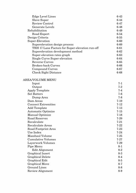
Edge Level Lines 6-43 Slave Super 6-44 Review Control 6-47 Generate Levels 6-48
Rehabilitation 6-49 Road Expert 6-54
Design Criteria 6-55 Super-Elevation 6-60 Superelevation design process 6-60 TRH 17 Lane Factors for Super-elevation run-off 6-61 Superelevation development method 6-62 Super-elevation rates graph 6-63 Single Curve Super-elevation 6-64 Reverse Curves 6-65 Broken-back Curves 6-66 Compound Curves 6-67 Check Sight Distance 6-68
AREA/VOLUME MENU Input 7-1 Output 7-2
Apply Template 7-4 Set Batters 7-6 Dump Area 7-8
Dam Areas 7-10 Connect Extremities 7-12 Add Template 7-13 Automatic Optimize 7-15 Manual Optimize 7-18 Road Reserves 7-20 Recalculate 7-21 Recalculate Areas 7-22 Road Footprint Area 7-23 Use Index 7-24 Masshaul Volume 7-25 Cumulative Volumes 7-27 Layerwork Volumes 7-29 Pipe Menu 8-1 Edit Alignment 8-2
Graphical Insert 8-3 Graphical Delete 8-4 Graphical Edit 8-5 Graphical Move 8-7 Ground Lines 8-8 Review Alignment 8-9

Auto Manholes 8-10 Auto Lengths 8-12 Parallel Pipes 8-14 Manhole Data 8-16 Invert Levels 8-18 Trench Volumes 8-19
TOOLS MENU Index 9-2 Chainage Record 9-2 Layer Record 9-3 List Chainage Records 9-5 Edit Chainage Record 9-6 Set Chainage Fields 9-7 Batch On/Off Switch 9-9 List Layer Records 9-10 Edit Layer Records 9-11 Set Layer Fields 9-13 Transfer Layer Fields 9-15 Batter Slope Extraction 9-17 Batter Slope Adjustment 9-18 Delete Chainage 9-20 Batch Chainage Deletion 9-21 Insert Chainage 9-22 Batch Chainage Insertion 9-23 Graphical Insertion 9-24
Construction 9-25 Profile/Batters 9-26 Offset Poles 9-28 Relative Poles 9-30 Cross Check 9-33 Full Level Table 9-34 Comparative Levels 9-36
Intersection 9-38 New Intersection 9-39 Load Intersection 9-44 Save Intersection 9-45 Edit Layout 9-45 Edit Curves 9-47 Review Layout 9-48 Calculate 9-49 Coordinate 9-50
Template Editor 9-52 Single Carriageway Templates 9-52 Dual Carriageway Templates 9-54

Compulsory Additions, Batters and Layerworks 9-56 TRH 4 Pavement Layer Designer 9-59 Pavement Designer 9-60 View Page 9-62
Template Paths 9-63 Chainage Equation 9-65

Welcome 1-1
Welcome
Welcome to Civil Designer, the design system created by civil engineers for civil engineers, to save you time, effort and money. Now you can work faster, smarter and accomplish more.
This manual introduces you to Civil Designer and gets you up and running without delay. It shows you how to accomplish the most common tasks and provides tips on the exciting and innovative new features to be found in Civil Designer.
The easy-to-follow tutorial will help you gain hands-on experience with the program, and the Beyond the Basics section shows you how to complete advanced tasks.
Where do I go from here?
After reading this manual you should know the following:
• How to get Civil Designer up and running
• How to use the menus and the on-line help system
• How to input and edit data files
• How to start an analysis
• How to view and output the results of the calculations
For more detail simply refer to the on-line help file: it contains over 700 pages of detailed information on each function.

1-2 Roads Reference
Typefaces in this manual
The different typefaces in this manual are used as follows:
Monospace This typeface represents text as it appears onscreen such as prompts.
Italics Italics are used for emphasis and to introduce new terms.
[Enter] This indicates a key on your keyboard or a button on the screen.
For example: “Press [Enter] to complete the entry.” or “Click on the [OK] button.”
Command This typeface indicates a menu option or a command.
For example: “Click on the Open icon to load a drawing.”
Menu commands appear with the path separated by an arrow. The instruction Draw ► Ellipses ► Ellipse refers to the command you choose by opening the Draw menu, the Ellipses sub-menu, and by choosing the Ellipse option.
Conventions used in this manual
In this manual, clicking refers to clicking with your left mouse button unless otherwise specified. When a click with your right mouse button is required, the terms right click or right clicking are used.
Clicking means to press and release a mouse button quickly.

Welcome 1-3
How to get support
Technical support is available from 08.00 to 17.00 Mondays to Fridays excluding public holidays from our Customer Support Centre at [email protected].
You can also call our Customer Support Centre at:
South Africa 086 0101 999
International +27 21 7011850
On-line help
The Civil Designer on-line help system is far easier to use and more comprehensive than those typically found in other software programs.
It contains about 10 times as much information as this manual and provides complete answers to virtually any question you may have about features or how to use Civil Designer.
Access on-line Help from the Help menu option at any time, or by pressing F1 during the display of any of the dialogs in the program. The help items can be printed using the Print icon on the toolbar.

1-4 Roads Reference
Online documentation
The manual is supplied on the installation CD-ROM in Adobe Acrobat PDF format. You have the option to install the Acrobat Reader when installing Civil Designer. This allows you to browse through the manual, to search for specific subjects, and to print out all or any selection of pages.
Basic Theory 2-1
Basic Theory
This section defines the fundamental concepts and terminology of the Civil Designer design modules.
Civil Designer deals with two different types of information:
• Terrain data, which consists of randomly ordered, irregularly spaced points that are directly defined in feature space by x, y and z ordinates.
• Section data, which consists of ordered but irregularly spaced points that are indirectly defined in feature space by offset and elevation.
Any one set of terrain data is contained in a single data file. Any one set of section data is termed a Road or a Pipeline and has two components to it: a file that holds the sections (offset/elevation pairs) and an associated design file that dictates the location of those sections, how they are formed and other pertinent information.
There is interaction and regular data exchange between a terrain file and the section files. Several section files can be associated with any one set of terrain data and that complete group of files is termed a "job". A job is managed by project file with a ".cdp" extension.
A typical job would have section files with ".nn.sec" extensions, design files with ".nn.des" extensions, a terrain file with a ".dtm" extension, and a file with ".cdp" extension that manages them. Note that the "nn" entry is a numerical figure from one upwards and is the road number in the job.
Various types of information may be used as input to design, build and maintain a Civil Designer job. Other types of information may be extracted by the program as end products or to be used as input to other software packages. Most of the types of data described so far are specific to a particular job. However, there are also data files that are universal in nature and will have application in many different jobs. These may be thought of as Resource files. Typical examples are the sheet templates that control the form of your plotted output, and road templates that govern the way a road is formed.
2-2 Roads Reference
Conventions
Civil Designer uses the following conventions in handling survey and cross section data.
Coordinate System
The program is configured to deal with horizontal, vertical and height ordinates.
Axes are based on a user-selected projection with horizontal ordinates increasing Westwards and vertical ordinates increasing to the South in Southern Hemisphere projections, and in the opposite directions for Northern Hemisphere projections. Horizontal ordinates (East-West axis) are always entered and listed before vertical ordinates (North-South axis) irrespective of the hemisphere.
A point may or may not have a height ordinate. If it does not, it is assigned a value of 0 and will be ignored in all terrain manipulation routines. All height ordinates are based on local Mean Sea Level (MSL).
Coordinates are stored internally as Latitude and Longitude based on a user-selected datum and prime meridian. Conversions to and from LO coordinates are carried out transparently. The maximum number of points possible in any one job is limited only by disk and memory capacity but has a theoretical upper limit in the region of 2 thousand million points.
Angular Measure
All angles are in degrees, minutes and seconds. In the case of vertical angles from theodolite readings, the assumed convention is 0 degrees vertically upward, 90 degrees horizontally on Circle Left, and 180 degrees vertically downward.
All programs that require entry of both Left Circle and Right Circle observations assume that face left will precede face right. Face right is always entered as 0 if it has not been observed.
Data entry uses the "d.mmss" convention. In other words, a reading of 125 degrees, 42 minutes and 6 seconds would be written 125.4206.
Path Names
Space has been allocated for the total allowable 260 characters in Windows 98/XP/2000.

Basic Theory 2-3
Point Names
Point identification and program operation are name based for the greatest operator convenience. A name may be up to sixteen characters in any alphanumeric form. Certain lower case characters are generated by the program and should be avoided.
They are:
• z - Bank shoulder and toe points
• x - Road sections converted to YXZ
These are added as a suffix to the names so that they can be readily identified subsequently.
There are also characters that are recognised for Name Filter purposes. These characters are - !, @, #, $, %, ^, & and *. They, and any characters following them in the name, are not displayed when point names are displayed.
Sections
Sections are stored as offset and elevation, increasing negative values to the left of the centre line and increasing positive values to the right. The cross-section offsets do not have to embrace the station itself so all the points can lie either to the left or right of the centre line.
The maximum number of chainages that can be collected is 65535. At each chainage up to 128 layers can be stored. The final layer is actually reserved for vertical curve data. Each of the layers may contain between 1 and 200 points, with an overall limit of 32767 points in all layers at any one chainage.
The chainage coordinates are also stored as latitude and longitude.

2-4 Roads Reference
Notes:

Tutorial - Roads Design 3-1
Tutorial - Roads Design
This example will teach you how to complete the following road design tasks:
• Select a road with which to work
• Input the horizontal alignment of a road
• Extract cross-sections from the terrain model
• Input the vertical alignment
• Define a road template
• Calculate the road levels
• Calculate the cross-section areas
• Calculate the volumes
• Create cross-sections
• Create long sections
• Create a site plan
Note that it is assumed that you have worked through the tutorial in the Design Centre manual, as this tutorial uses the ground model that was created in that exercise. Select the File ► Open Project… option from the menu and open the Tutor project that you worked on previously.

3-2 Roads Reference
Select the working road
Before we start with a road design we should select the particular road with which we wish to work.
Civil Designer allows up to 250 roads to be associated with any terrain file. If you do not select a particular road before using the Road functions, Civil Designer will default to using Road 1 if no other roads have been selected previously or will default to the last used road (be that road 1 or otherwise).
Switch to the Road Mode by selecting Mode ► Road from the menu or by clicking on the Road icon in the Design Mode toolbar. Select the File ►
Select Road File option from the menu. The following dialog will be displayed:
We will be working with road 1 in this tutorial. The default description (Road1) is, however, not suitable so let’s change it. With the highlight on the first road click on the [Edit] button and the following dialog will be displayed:

Tutorial - Roads Design 3-3
Change the default road name as shown above, and also rename the first two layers in the road as above. During this tutorial we will be storing ground cross-section data to layer 1 (now named Ground) and road cross-section data to layer 2 (now named Final Road).
It is handy to retain the road number as part of the road name as this number is stored as part of the file name, and this makes it easier to associate on-disk files with particular roads.
Click the [OK] button to return to the previous dialog and click on [OK] again to select road 1 as the working road. The name of the working road will be displayed in the Design Center title bar.

3-4 Roads Reference
Input the horizontal alignment
The very first step is to define the horizontal alignment by entering the data manually into a spreadsheet, by ASCII data import, or graphically. In this exercise we will input the alignment data using the Spreadsheet window.
Select the Alignment ► Horizontal ► Edit alignment option from the menu. The Spreadsheet window will be displayed so that we can input or edit the horizontal alignment data. Input the following values:
Now minimize the Spreadsheet window and press S (for refreSh) to refresh the Design Center window. You will see that your horizontal alignment is plotted on the ground model.

Tutorial - Roads Design 3-5
Changing the alignment
You can change the alignment very easily by selecting one of the edit, insert, delete or move HPI functions on the toolbar on the left of the layout window. The move function also allows you to move the BC or EC positions which will result in the radius being changed.
Review and coordinate
Once you are happy with the horizontal alignment select the Alignment ►
Horizontal ► Review Alignment menu option.
Click on NO in the message box that ask spreadsheet output and choose screen output in the next message box. Open the Output window to view the detail of each horizontal curve. If you cannot see the output window then select Windows ► Toggle Output Window.
3-6 Roads Reference
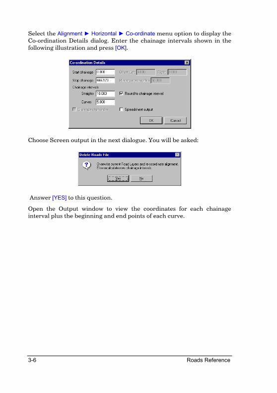
Select the Alignment ► Horizontal ► Co-ordinate menu option to display the Co-ordination Details dialog. Enter the chainage intervals shown in the following illustration and press [OK].
Choose Screen output in the next dialogue. You will be asked:
Answer [YES] to this question.
Open the Output window to view the coordinates for each chainage interval plus the beginning and end points of each curve.

Tutorial - Roads Design 3-7

3-8 Roads Reference
Extract cross-sections
The next step in our road design is to extract the cross- sections from the Terrain model at each chainage along the centerline of the road.
Select the Alignment ► Horizontal ► Cross Sections ► Extract menu option. The Cross Section Extraction dialog will be displayed. Enter the details as shown below and press [OK].
Civil Designer will extract and save the ground line cross- sections into Layer 1 of the road design. To view the cross-section offsets and elevations open the Output window.

Tutorial - Roads Design 3-9
Vertical alignment
We can define the vertical alignment graphically or by entering the chainage and levels into the Spreadsheet window. We will use the latter method to input the data and the graphical facilities to view the vertical alignment and make small changes, if required.
Activate the Road menu again and select the Alignment ► Vertical ► Edit
Alignment option. To see the active windows select the Windows ►
Cascade option. Now select the Vertical Alignment spreadsheet so that you can specify the vertical alignment.
Click on the [Single-LHS] tag at the bottom of the spreadsheet and enter the following data:
In order to check our data we can display the vertical alignment plus up to 4 ground lines in the Road window. To do this, select the Alignment ►
Vertical ► Ground Lines menu option, or click the Ground Lines icon on the toolbar on the left of the Road window, and set the line detail as shown below:

3-10 Roads Reference
Select the Road Window, which should look like this:
The red line shows the vertical alignment while the other lines show the ground line at the centreline (dark green), the ground line at the road reserve 8m to the left of the centreline (light green), and the ground line at the road reserve 8m to the right of the centre line.
The information bar on top of the vertical alignment will display curve information dynamically while you move the cursor over the vertical curves.
Move around the vertical long section plot using the panning keys exactly as in the Design Centre window.
To change a VPI simply click on it and the following dialog is displayed:

Tutorial - Roads Design 3-11
To change the alignment graphically simply select one of the insert, delete, move or edit functions from the toolbar on the left of the Road window. Note how the spreadsheet is continuously updated.
When you are happy with the grade line you can send the vertical alignment information to the Output Window, printer or file by selecting Vertical ► Review Alignment.
Now generate the levels along the centerline using the Alignment ►
Vertical ► Generate levels function. The levels will be displayed in the Output window. Note that all the high and low points on the alignment are flagged.
Now is a good time to save your data.

3-12 Roads Reference
Define a road template
Once the vertical alignment has been defined, a road template must be applied along the alignment in order to calculate the final sections and the earthworks quantities. We can either load an existing template, or create a new one.
Select the Tools ► Template Editor option from the Road menu. The Road Profile Editor dialog will be shown. Check the Single Carriageway option and fill in the details as shown:
The carriageway portion of the template will be displayed on the View tab. Now we must specify the compulsory and cut/fill conditions for the new template.
Note: The carriageway settings (crossfalls and widths) will be superceded by the values specified in the Edge Levels Spreadsheet, where you will be entering superelevation and road widening.

Tutorial - Roads Design 3-13
Compulsory items are added to the template on every section, i.e. kerbs, gutters and/or pavements. Cut and fill conditions will be applied depending on the position of the template relative to the ground line starting from the last compulsory point.
All additions are specified as horizontal and vertical offsets from the previous point on the template.
Select the correct tab in the spreadsheet to add the compulsory and cut/fill conditions.
Compulsory additions
We are going to add gutter kerbs to each side of the template as a compulsory addition. Click on the [LComp] tag at the bottom of the spreadsheet and enter the following values:
We could re-enter the same data for the right compulsory additions, but it is much easier to copy the data. Use the mouse to select all the [LComp] cells and copy the data to the clipboard by right clicking on the selection. The following option list will be displayed:
Select the Copy option. Now click on the [RComp] tag to display the right compulsory values. Select the same amount of cells and paste the clipboard data by right clicking and selecting the Paste option.

3-14 Roads Reference
Cut and fill conditions
Click on the [LCut] tag to enter the left cut detail:
Here we can see that there are two cut conditions that will be applied for different depths of cut.
• The first case is for a cut depth between 0.0 and 2.0 m. Here the cut slope will be variable from the last compulsory point to the edge of the road reserve at 5 m from the centerline. Should the cut slope exceed 1:2 the toe point will be extended beyond the road reserve at the 1:2 slope.
• In the second case, where the cut depth is between 2.0 and 999.0 m, a cut slope of 1:1.5 will be used.
You may have up to 100 cut or fill incremental conditions. The cut and fill conditions must always end off with a Max Ht value of 999.0.
Copy the left cut specification across to the right cut data page on the spreadsheet as was done previously.
Click on the [LFill] tag to enter the left fill details as displayed below:

Tutorial - Roads Design 3-15
Copy these details to the [RFill] page as before.
Specify a Pavement design
Click on the [LLayers] tag to display the layerwork left details. Right click on the spreadsheet to display the popup menu.
Select the [TRH4 Pavements] from the popup menu. You can also specify your own pavements by using the [Pavement Designer] option.
In this dialog the appearance of the large buttons is dependant on the preceding selections. The program will then display possible pavement designs according to the TRH4. Some combinations of selections have no layer definitions, some have only one (in which case the left button will be visible) and some have two (in which case both buttons will be visible).

3-16 Roads Reference
Change the settings as follows:
Select either one of the two options displayed. The template definitions will be added to the “LLayers” sheet automatically.
The layers can now be stepped by changing the “Left Shift” and “Right Shift” values as follows:
Preview
Before we continue, we can test the template to see how the conditions are applied. Click on the View tab to view the template and then on the [Add Ground] button. Draw a ground line on the displayed template. You may use the standard keys to zoom in or out.

Tutorial - Roads Design 3-17
Click on the [Test] button and the editor will apply the appropriate cut and/or fill conditions so that you can check whether the template is correct.
Repeat to experiment with various ground lines.
Finally, we must save the template as URBAN.TEM using the [Save As] button. You may now exit the Template Editor.

3-18 Roads Reference
Template Number
The template we have just created must be added to the road design file.
Select the Tools ► Template Paths menu option.
Use the […] button in the first row to select the new template file. Enter a template name, say “urban” into the Name column.
You must refer to the templates by their template names, rather than the file names, in all the functions that use road templates.
In this manner up to 100 templates may be added to a design file.

Tutorial - Roads Design 3-19
Calculate the road levels
Now that we have defined a road template we must calculate the road edge levels along the vertical alignment using the template. We can also add super elevation and road width controls here.
There are two methods of defining the super elevation details. The first is to enter the super elevation directly into the Spreadsheet window using the Alignment ► Edge Levels ► Edit Super option, which is suitable for urban streets.
The second bases the control data on the horizontal alignment using the [Slave Super] option and is more suited to rural roads. As our example is an urban street we will use the former option.
Select the Alignment ► Edge Levels ► Edit Super menu option. Enter the super elevation details in the various tabs as illustrated below:
These Edge Control settings specify that the road has a 2% camber, carriageway widths of 3.1m, and uses template “urban” from the start to the end of the road.

3-20 Roads Reference
Calculate the road edge levels by using the Alignment ► Edge Levels ►
Generate Levels menu option. Note that the destination surface is Final Road (layer 2) as we have already stored the ground line data in Ground (layer 1).
The depth below the vertical alignment is specified as 0 as we are working on the final road surface. You can view the results in the Output window. Once again, now is a good time to save your work.

Tutorial - Roads Design 3-21
Calculate the cross section areas
Once the ground and final road cross-sections are defined we can apply the template and calculate the cross-sectional areas.
Select the Area/Volume ► Apply Template option from the Road menu. Input the chainage range and the base and batter layers as illustrated. Note that you can output the areas directly into an ASCII file by checking the Spreadsheet output option.
As the cross-section areas are calculated they will be displayed in the Road window. View the calculated results in the Output window and save your work.

3-22 Roads Reference
Calculate the volumes
At this point we can calculate cut and fill volumes for our road. Select the Area/Volume ► Masshaul Volume menu option from the Road menu. Specify the volume calculation details in the next dialog. Note the topsoil depth, compaction or bulking factor and the batter layer values:
You can also output the quantities to an ASCII file by checking the Spreadsheet output option.
Press [OK] to calculate the volumes. The dialog will be displayed again with new start and end chainage values but this time, just click on the [Print Results] button to view a summary of the cut and fill volumes in the Output window.
Calculating Layerwork volumes
We can calculate the cut and fill volumes for each pavement layer as specified in the road template.
Select the Area/Volume ► Layerwork Volume menu option.
Press [OK] to calculate the cut and fill volume for each layer.

Tutorial - Roads Design 3-23
The following output will be displayed in the Output window.

3-24 Roads Reference
Create a cross-section drawing
Select the Plot ► Generate option from the Road menu to start the Plot Expert. Use the Cross Section.sht sheet from the Examples\SheetFiles sub-directory and specify a sheet size of A0.
Click on the [Next] button to continue. Specify the plotting details in the Cross Section Setup dialog as follows:

Tutorial - Roads Design 3-25
You can plot cross-sections consisting of up to 20 lines drawn from the various layers in the road file. For the purposes of this tutorial we are only interested in the Ground and Final Road layers.
Click on the [Finish] button and a drawing similar to the following should be generated (You will be asked for a filename to save to before the drawing is displayed. Just click [Cancel] to ignore the option):
The drawing is generated into its own CAD window so you can now pan around, magnify, demagnify and use the drawing functions to add any embellishments you wish.
When you are done click on the Close icon at the top right of the CAD window to close the window.

3-26 Roads Reference
Create a long section drawing
Typically you would generate the long section from the cross-section data. Once again select the Plot ► Generate menu option from the Road Menu. Use the Single Carriageway Longsection.SHT sheet from the ..\Samples\SheetFiles sub-directory and once again select a sheet size of A0:
Click on the [Next] button to continue and then set the chainage range and other plotting details as shown below:

Tutorial - Roads Design 3-27
You can plot long sections consisting of up to 20 lines drawn from the various layers in the road file. You can also specify what data (Chainage, Offset or Elevation) should be extracted from each cross-section.
In our case we are plotting the ground line from the Ground layer (line 1 above), the left and right edges of the road from Final Road (lines 2 and 4 respectively), and the centerline from Final Road (line 3). In each case we are extracting the elevation from the cross-section.
Point Location Codes
Where the left and right edges of the road are concerned, we have chosen to define the position in the cross-section by Point Location Code (PLC) rather than by a physical offset from the centerline. This allows us to cope with roads that have had carriageway widening applied without having to worry about the exact measurement of the offset at any particular chainage.
A PLC of 1 (negative for left of centerline and positive for right) will always extract the first point away from the centerline on the specified side regardless of what the offset might be. Conversely, a PLC of 99 (using the same convention for left and right of centerline) will always extract the last point in a cross-section (the toe line).
The convention for the use of PLC’s is that codes from 1 to 50 are counted out from the centerline (which has a PLC of 0), and codes from 51 to 99 are first subtracted from 100 and then counted in from the last point in the section. In all cases a negative PLC is left of the centerline and a positive PLC is right of the centerline.
In the case of dual carriageway roads two extra PLC codes are available. These are the codes 100 (which represents the shoulder break point on the left or right carriageway) and 101 (which represents the median break point on the relevant carriageway). These codes can also be used on a single carriageway road but only the 100 code will actually operate.
Click on the [Next] button and the long section data will be displayed.

3-28 Roads Reference
Click on the [Finish] button and a drawing similar to the following will be generated (You will be asked for a filename for saving but you can once again just click [Cancel] to ignore the option):
You will be asked in the prompt area to adjust the Long Sections scales. Reply no by clicking on the cross.

Tutorial - Roads Design 3-29
Create a site plan
As the last step in this tutorial we will create a site plan that includes the road and terrace detail.
Because Civil Designer uses a WYSIWIG (What You See Is What You Get) model for plan plotting, we need to set up the Design Center display to show exactly what we want to see in the site plan.
Click on the Display Dialog icon or select Settings ► Display Settings to open the Display Settings dialog.
In the Roads section check the Display road plan option, make sure that Yes is displayed in the Vis. column next to Road 1 (if it isn’t then simply right-click on the cell to toggle its value) and make the Current road settings as shown:
We also need to set up the display itself so click on the “Plan Layout” tab and make the following settings:

3-30 Roads Reference
Before clicking on [OK] to update the display switch to the Terrain tab and make sure that the Draft Text option is not checked. Also select to display contours in order to make our site plan more visually exciting.
Select the Plot ► Generate menu option and specify Plan.SHT as the sheet file and an A0 sheet size:
Click on the [Next] button and accept the values in the following dialog and click on the [Next] button.

Tutorial - Roads Design 3-31
In the following dialog specify the scale for the plot and the options as shown:
Click on the [Redefine All] button. The layout window will be displayed and you will be asked to indicate the center of the plot. A rectangle the

3-32 Roads Reference
size of the plotting area will be displayed. Left-click on the display and then move this rectangle to cover the area of interest and left click to place it. You will then be asked if you wish to rotate the plot. Click on [No]. The previous dialog will be shown with a new entry that you have created. Accept it by clicking on the [Finish] button. A drawing similar to the following will be generated:

File Menu 4-1
File Menu
The File Menu contains all the functions to create, load and save projects as well as import and export survey data. In addition it also includes options to set up the security.

4-2 Roads Reference
New Project
Create a new project
Icon Button Toolbar Shortcut Command
ProjectNew
This option allows you to set up a new project and specify the data files that must be used.
Procedure
The Project dialog is displayed.
To add a drawing to the project simply click in the check box next to Drawing, click on Browse on the right of the dialog, and select the drawing using the standard Window file open dialog. The drawing name will be displayed as shown above.
To add a drawing to the project simply click in the check box next to Drawing, click on Browse on the right of the dialog, and select the drawing using the Window's standard open dialog. The drawing name will be displayed as shown above.

File Menu 4-3
Similarly, to add a data file to the project click in the check box next to the required data type and select the file to use with the [Browse] button. If the file does not exist it will be created.
To use the Survey, Terrain or Roads functions, you must select or create a Terrain data file.
Drawing File
You may only use an existing drawing file. The drawing may be an AllyCAD DRG, AutoCAD DWG, Caddie CEX or a DXF file.
Terrain File
If you select a terrain file that does not exist, the following dialog will be displayed:
Click on Yes to create the DTM file.
After you have clicked [OK] on the New Project Dialog the following dialog will be displayed for a new DTM file.
Enter the Y and X coordinates of the centre of the site, or of the area of principal interest, and a diameter that will encompass the site or, once again, the area of principal interest. It is acceptable to leave the settings at their default values, but you should then either import data from an ASCII file which will offer a rescale that centres the site, or add data manually and then use Tools ► Rescale Survey from the Terrain menu which does the same thing.

4-4 Roads Reference
Sewer File
If you select a sewer file that does not exist, the following dialog will be displayed:
Click on Yes to create the sewer database file.
Storm File
If you select a storm file that does not exist, the following dialog will be displayed:
Click on Yes to create the storm database file.
Locale
You must make the settings that determine the manner in which the stored coordinates are projected onto the display surface (the Design Centre window).
Hemisphere
Select either the Southern Hemisphere or Northern Hemisphere options to set the hemisphere in which the data is located.
Projection
Select the mapping projection to be used. Currently only three projections are available, namely Local, Transverse Mercator and UTM (Universal Transverse Mercator). Selecting Local will automatically set the Datum to Cape and causes Civil Designer to treat the Terrain and Road database coordinates in the same way as Stardust used to.
Datum

File Menu 4-5
Select the datum on which the data is to be based. This determines the ellipsoid on which the projection is based and therefore the constants used for the mapping projection. Note that the Cape datum is the equivalent datum for that used by Stardust.
Prime Longitude
Enter the central LO of the panel in which the data falls (actually the longitude on which the 0 value of the horizontal ordinates of the coordinate system falls) and also select whether this LO is East or West of 0° longitude (Greenwich).
Origin Latitude
Enter the latitude on which the 0 value of the vertical ordinates of the coordinate system falls and also select whether this latitude is North or South of 0° latitude (the Equator). This should normally be set to 0° (origin at the equator where North or South are immaterial) but could be different for some projections.
Scale factor at prime longitude
Enter the factor by which coordinates are adjusted in order to fit the projection. This should normally be set to 1.0 except if you are using UTM coordinates (see Remarks below).
False Easting and False Northing
Enter the values to be subtracted/added to the LO coordinates during projection conversion. These should normally be set to 0 except if you are using UTM coordinates (see below).
DO NOT use the False Easting and False Northing settings to apply some constant to the data coordinates, as the projection calculations rely on full coordinates and will give incorrect values if these entries are used incorrectly.
Remarks
In order to use a UTM system the following settings should be made for Locale:
• Convert the UTM block number to LO using the formula (BLOCKNUMBER x 6°) - 183°. This calculates the Longitude of the central meridian in degrees.
• Set the scale factor at the central meridian to 0.9996.

4-6 Roads Reference
• Enter the correct False Easting and False Northing values of +500 000m Easting, and 0m Northing for Northern Hemisphere or +10 000 000m Northing for Southern Hemisphere.

File Menu 4-7
Open Project
Load an existing project
Icon Button Toolbar Shortcut Command
ProjectOpen
You can select which project to open using the standard Windows Open dialog.
Procedure
The Open dialog will be displayed.
Select the project file (.CDP) to open and click on [OK].
The existing project (if any) will be saved and the new project will be opened. The associated data files will automatically be opened and displayed in the Design Centre.
Only data that includes coordinates can be displayed in the Design Centre.

4-8 Roads Reference
Edit Project
Edit the current project
Icon Button Toolbar Shortcut Command
ProjectEdit
This option allows you to add design elements to the project or to change the data files associated with the project.
Procedure
The Project dialog is displayed.
To add a design element to the project simply set the check box of that element and select the data file using the [Browse] button. The standard Window Open dialog will be displayed. Select the file to add to the project or type in a new file name to create a new data file.
You may not change the locale settings of an existing project as the projection settings have already been applied to data files and may not be changed.
Click on the [OK] button.

File Menu 4-9
Save Project
Save the current project
Icon Button Toolbar Shortcut Command
ProjectSave
This option allows you to save the current project and the associated data files.
Save Project As
Save the current project to another name
Icon Button Toolbar Shortcut Command
ProjectSaveAs
This option allows you to save the current project and the associated data files to new file names. You may specify a new file name for the project file and each of the active design files in turn.
Close Project
Close the current project
Icon Button Toolbar Shortcut Command
ProjectClose
This option allows you to close the active project and clear the Design Centre. You will be given the option to save the associated data files.

4-10 Roads Reference
Select Road File
Select a road file with which to work
Icon Button Toolbar Shortcut Command
RoadSectionFile
Any road file that you wish to work on has to be loaded from this item under the Roads Menu File option.
The [Edit] button on the Road Selection dialog allows you to enter a new description for your road as well as setting the names of the various layers. The description of the current Road will be displayed on the Design Centre title bar and on the Road window title bar when any of the Roads routines that use that window are activated.
A section file to store pipeline sections also has to be selected under this option.
Procedure
The Road Selection dialog is displayed.
List Box Click on a road name in the list to select it. You can also double click a road name in the list to select it and automatically close the dialog at the same time.
Edit Button Click this button to edit the road and layer names of the selected road. The Road Name Edit dialog will be displayed.

File Menu 4-11
Delete Button Click this button to delete the roads files (*.sec and *.des). The Road Name will be replaced with the default road name.
Copy Road Click this button to copy the selected road to another road. You will be prompted for a destination road.
OK Button Click this button to accept the selected road.
Cancel Button Click this button to retain the previously selected road.
Select the required road and then click the [OK] button to continue.
To edit the description and layer names of any road, click on the desired road and then click the [Edit] button. The Road Name Edit dialog is displayed.
Edit box Type in the display name you wish to be assigned to this road when selected.
Name column Enter the names that you wish to be assigned to the available layers in the selected road.
Fill in the relevant data and click the [OK] button to continue.

4-12 Roads Reference
Import
This facility allows you to import ASCII cross and long sections. You are prompted to choose a file to import and must specify the details of the format of the file in the dialog box that follows.
When importing Cross Section and Long Section files, the data will automatically be imported into the current Road file. Therefore, you should select the relevant road before importing data.
When importing Cross Sections, an option is available to import the data with or without a cross section counter. The counter specifies how many points there are for each specific cross section and was a requirement for earlier versions of Stardust.
ASCII Cross Sections
Import cross sections in ASCII format
Icon Button Toolbar Shortcut Command
RoadImportCross
This facility allows you to import ASCII cross sections. You are prompted to choose a file to import and must specify the details of the format of the file in the dialog box that follows. The data format that can be imported is as follows (in comma-delimited format):
Chainage,0.000,Pts,12
-5.000,98.002,0
-5.000,99.347,0
-4.200,99.334,0
-3.001,99.314,0
-3.000,99.064,1
0.000,99.124,1
3.000,99.064,1
3.001,99.314,0
4.200,99.334,1
7.200,98.834,0
9.700,99.459,0
9.700,101.852,0

File Menu 4-13
Procedure
Windows’ standard open dialog is displayed in order for you to select a file to import. The drive and path automatically default to the last used drive and directory for this type of file.
The ASCII Cross Section File Details dialog is displayed.
Fixed columns - Start and Stop
Enter the positions of the specific items within each import line. Positions start at 1 at the beginning of the line. The start and stop positions entered for any particular item must be such that all the relevant data for the item is covered.
ASCII delimiter - Field Enter the position of each specific item within the import line. Positions start at 1 for the item before the first occurence of the defined delimiter. Each delimiter encountered along the line increases the position count by 1.
File Type Select either Fixed columns or ASCII delimiter to define the format of the file being imported. If you select ASCII delimiter then you must also enter the ASCII value of the delimiter between fields.
Use section counter Check this option in order to have the count of lines following read from the first line of each cross section in the file. This option is not available when importing Cards format cross sections.
Save current settings Check this option to have the current settings saved as defaults for the next time this dialog is invoked.
Fill in the relevant data and click the [OK] button to continue. The ASCII Cross Section Import Details dialog is displayed.

4-14 Roads Reference
Start Chainage Enter the first chainage of the range of chainages to process.
Stop Chainage Enter the last chainage of the range of chainages to process.
Layer Select the layer on which to store the imported cross sections.
Add constants to sections Check this option to have constants added to the offsets and elevations as they are imported.
Constant Details - Chainages Enter the constant to be added to chainages as data is imported.
Constant Details - Elevations Enter the constant to be added to elevations as data is imported.
Fill in the relevant data and click the [OK] button to continue. The Output Manager dialog is displayed in order for you to set output options. Click the [OK] button to accept the settings.
File Menu 4-15
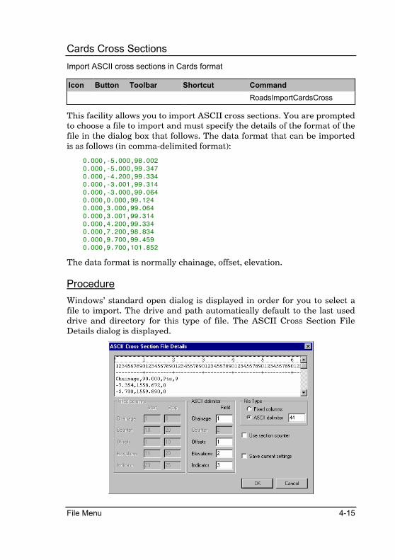
Cards Cross Sections
Import ASCII cross sections in Cards format
Icon Button Toolbar Shortcut Command
RoadsImportCardsCross
This facility allows you to import ASCII cross sections. You are prompted to choose a file to import and must specify the details of the format of the file in the dialog box that follows. The data format that can be imported is as follows (in comma-delimited format):
0.000,-5.000,98.002
0.000,-5.000,99.347
0.000,-4.200,99.334
0.000,-3.001,99.314
0.000,-3.000,99.064
0.000,0.000,99.124
0.000,3.000,99.064
0.000,3.001,99.314
0.000,4.200,99.334
0.000,7.200,98.834
0.000,9.700,99.459
0.000,9.700,101.852
The data format is normally chainage, offset, elevation.
Procedure
Windows’ standard open dialog is displayed in order for you to select a file to import. The drive and path automatically default to the last used drive and directory for this type of file. The ASCII Cross Section File Details dialog is displayed.

4-16 Roads Reference
Fixed columns - Start and Stop
Enter the positions of the specific items within each import line. Positions start at 1 at the beginning of the line. The start and stop positions entered for any particular item must be such that all the relevant data for the item is covered.
ASCII delimiter - Field Enter the position of each specific item within the import line. Positions start at 1 for the item before the first occurence of the defined delimiter. Each delimiter encountered along the line increases the position count by 1.
File Type Select either Fixed columns or ASCII delimiter to define the format of the file being imported. If you select ASCII delimiter then you must also enter the ASCII value of the delimiter between fields.
Use section counter Check this option in order to have the count of lines following read from the first line of each cross section in the file. This option is not available when importing Cards format cross sections.
Save current settings Check this option to have the current settings saved as defaults for the next time this dialog is invoked.
Fill in the relevant data and click the [OK] button to continue. The ASCII Cross Section Import Details dialog is displayed.
Start Chainage Enter the first chainage of the range of chainages to process.
Stop Chainage Enter the last chainage of the range of chainages to process.
Layer Select the layer on which to store the imported cross sections.
Add constants to sections Check this option to have constants added to the offsets and elevations as they are imported.
Constant Details - Chainages Enter the constant to be added to chainages as data is imported.
Constant Details - Elevations Enter the constant to be added to elevations as data is imported.

File Menu 4-17
Fill in the relevant data and click the [OK] button to continue. The Output Manager dialog is displayed in order for you to set output options. Click the [OK] button to accept the settings.

4-18 Roads Reference
Long Section
Import long sections in ASCII format
Icon Button Toolbar Shortcut Command
RoadImportLong
This facility allows you to import ASCII long sections. You are prompted to choose a file to import and must specify the details of the format of the file in the dialog box that follows.
Procedure
Windows’ standard open dialog is displayed in order for you to select a file to import. The drive and path automatically default to the last used drive and directory for this type of file.
The ASCII Longsection File Details dialog is displayed.
The first few lines of the selected file are displayed in the top list box.
Fixed columns - Start and Stop
Enter the positions of the specific items within each import line. Positions start at 1 at the beginning of the line. The start and stop positions entered for any particular item must be such that all the relevant data for the item is covered.
ASCII delimiter - Field Enter the position of each specific item within the import line. Positions start at 1 for the item before the first occurence of the defined delimiter. Each delimiter encountered along the line increases the position count by 1.
File type Select either Fixed columns or ASCII delimiter to define the format of the file being imported. If you select ASCII delimiter then you must also enter the ASCII value of the delimiter between fields. See the ASCII table for delimiter values.

File Menu 4-19
Fill in the relevant data and click the [OK] button to continue. The ASCII Cross Section Import Details dialog is displayed.
Start Chainage Enter the first chainage of the range of chainages to process.
Stop Chainage Enter the last chainage of the range of chainages to process.
Layer Select the layer on which to store the imported cross sections.
Add constants to sections Check this option to have constants added to the offsets and elevations as they are imported.
Constant Details - Chainages Enter the constant to be added to chainages as data is imported.
Constant Details - Elevations Enter the constant to be added to elevations as data is imported.
Fill in the relevant data and click the [OK] button to continue. The Output Manager dialog is displayed in order for you to set output options. Click the [OK] button to accept the settings.

4-20 Roads Reference
R?? File
Import data from a Stardust road file.
Icon Button Toolbar Shortcut Command
RoadImportRD
This routine allows you to import road data that was created in the previous Stardust versions (4.3 or later). You must select a road file before starting the import.
Procedure
Windows’ standard open dialog is displayed in order for you to select a file to import. The drive and path automatically default to the last used drive and directory for this type of file.
The Constants dialog is displayed.
Fill in the constants and click the [OK] button to continue. The following message is displayed:
Click the [Yes] button to overwrite any existing road file with the imported data, or click the [No] button to cancel the import.
The road data is imported into the current road file overwriting any data that is currently present.
The following message is displayed if the imported road contained template references:

File Menu 4-21
You will need to either import the old template files for this road, or create new ones, and use Tools ð Template Paths to update the references.
The following message is displayed if the imported road was a dual carriageway road:
Stardust previously read the carriageway details for single carriageway roads from the Edge Levels data while the details for dual carriageway roads were read from the assigned templates. In Civil Designer however, the details for both types of roads are read from the Edge Levels data. This means that you will need to edit the imported Edge Levels data for dual carriageway roads.

4-22 Roads Reference
Ceaser Design
Import a Ceaser Template file.
Icon Button Toolbar Shortcut Command
RoadImportCeaser
This facility allows you to import a Ceaser Template. You are prompted to choose a file to import and as well as the Road to import the data to.
Procedure
Windows’ standard open dialog is displayed in order for you to select a file to import. The drive and path automatically default to the last used drive and directory for this type of file.
The Import Ceaser dialog is displayed.
Specify the Road into which the data must be imported and press [OK].
If the import was successful then the confirmation dialog will be displayed.

File Menu 4-23
Export
The following functions allow you to export road cross sections in various formats.
Cross Sections
Export cross sections from the current road file in ASCII format
Icon Button Toolbar Shortcut Command
RoadExportCross
This facility allows you to export ASCII cross sections.
Procedure
The ASCII Cross Section dialog is displayed.
Start chainage First chainage in the range of chainages for which cross or long sections should be exported.
Stop chainage Last chainage in the range of chainages for which cross or long sections should be exported.
Layer The layer containing the cross or long section points to be exported.
Add constants to sections Check this option to have the entered constants added to the data as it is exported.
Constants - Chainage Enter the constant to be added to chainages.
Constants - Elevation Enter the constant to be added to elevations.
Fill in the relevant data and click the [OK] button to continue. Windows’ standard save dialog is displayed in order for you to select a file to which to write. The drive and path automatically default to the last used drive and directory for this type of file.
The Output Manager dialog is displayed in order for you to set output options. Click the [OK] button to accept the settings.

4-24 Roads Reference
Long Section
Export a long section from the current road file in ASCII format
Icon Button Toolbar Shortcut Command
RoadExportLong
This facility allows you to export an ASCII long section.
Procedure
The ASCII Cross Section dialog is displayed.
Start chainage First chainage in the range of chainages for which cross or long sections should be exported.
Stop chainage Last chainage in the range of chainages for which cross or long sections should be exported.
Layer The layer containing the cross or long section points to be exported.
Add constants to sections Check this option to have the entered constants added to the data as it is exported.
Constants - Chainage Enter the constant to be added to chainages.
Constants - Elevation Enter the constant to be added to elevations.
Fill in the relevant data and click [OK] to continue. Windows’ standard save dialog is displayed in order for you to select a file to which to write. The drive and path automatically default to the last used drive and directory for this type of file.
The Output Manager dialog is displayed in order for you to set output options. Click the [OK] button to accept the settings.

File Menu 4-25
Ceaser Survey
Export a road design to Ceaser
Icon Button Toolbar Shortcut Command
RoadExportLong
This facility allows you to export the current road design to Ceaser. You are prompted to select the batter Layer to Export.
Procedure
The Ceaser Export Dialog will be displayed
Select the roads layer containing the road design and press OK. This layer may be the final design layer, or a layer created by the Solidify Layerworks function as long as the batters are included in the layer. A range of ASCII files will be written to the directory where the Roads files reside.
If the Export was successful, a Confirmation dialog will appear.
Export MX Roads (Moss)
Export a road design to MX Roads
Icon Button Toolbar Shortcut Command
RoadExportMoss

4-26 Roads Reference
This facility allows you to export the current road design to MX Roads in MOSS format.
Procedure
The Export to MOSS\MX Roads Dialog will be displayed.
Specify destination ASCII files for the Horizontal and Vertical alignment, as well as an ASCII file additional strings. For each ID specified in the ID list a string will be created. Strings for the toe points, shoulder breakpoints, median breakpoints and centre line will automatically generated. Specify the road batter layer.

File Menu 4-27
Output Manager
Set output defaults
Icon Button Toolbar Shortcut Command
OutputManager
This function allows you to set up the Output Window's printing and file export capabilities. If you select to send output to the screen and the Output Window is not visible, use Window | Toggle Output Window to display the window.
Procedure
The Output Manager is displayed.
Screen output Check this option to have output directed to the Output Window. If this window is not visible then select Window | Toggle Output Window
Printer output Check this option to have output directed to a selected printer. If this option was selected and you now turn it off, any output previously directed to the printer will be spooled. If this option was not selected and you now turn it on, you will be asked to select the required printer.
File output Check this option to have output directed to a file. If this option was selected and you now turn it off, the output file will be closed. If this option was not selected and you now turn it on, the selected output file will be created.
Don't show this dialog in future
Check this option to retain the current settings for all future output. You will no longer be prompted to make settings. In order to adjust the settings, or to turn off this option, use File | Output Manager.
Page Heading Enter the heading to be printed at the top of each page. Only available if the Printer output option is selected.
4-28 Roads Reference
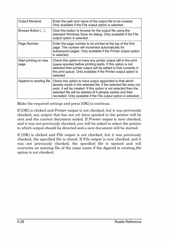
Output filename Enter the path and name of the output file to be created. Only available if the File output option is selected.
Browse Button (...) Click this button to browse for the output file using the standard Windows Save As dialog. Only available if the File output option is selected.
Page Number Enter the page number to be printed at the top of the first page. The number will increment automatically for subsequent pages. Only available if the Printer output option is selected.
Start printing on new page
Check this option to have any printer output still in the print queue spooled before printing starts. If this option is not selected then printer output will be added to that currently in the print queue. Only available if the Printer output option is selected.
Append to existing file Check this option to have output appended to that which already exists in the selected file. If the selected file does not exist, it will be created. If this option is not selected then the selected file will be deleted (if it already exists) and then recreated. Only available if the File output option is selected.
Make the required settings and press [OK] to continue.
If [OK] is clicked and Printer output is not checked, but it was previously checked, any output that has not yet been spooled to the printer will be sent and the current document ended. If Printer output is now checked, and it was not previously checked, you will be asked to select the printer to which output should be directed and a new document will be started.
If [OK] is clicked and File output is not checked, but it was previously checked, the specified file is closed. If File output is now checked, and it was not previously checked, the specified file is opened and will overwrite an existing file of the same name if the Append to existing file option is not checked.

File Menu 4-29
Spool Output
Spool unprinted data to the printer
Icon Button Toolbar Shortcut Command
OutputSpool
Any output (print) data that has been sent to the printer but not yet printed is spooled to the printer.
Windows tends to hold printed output in a spool file until the print job is complete. In order to end a print job in Civil Designer you must deselect the print option in the Output Manager, or exit the program. Alternatively, this function will carry out the same procedure.

4-30 Roads Reference
Option Settings
Set INI file defaults that are not set by the program
Icon Button Toolbar Shortcut Command
OptionSettings
The settings for various items in Civil Designer are stored in the file CivDes6.ini which is located in your User directory. While most settings in this file are manipulated from within the program itself, some settings have no menu option or dialog associated with them.
In order to facilitate the changing of these settings, we have implemented a dialog specifically for adjusting these settings. This saves you from having to edit the INI file and making the changes by hand.
The left side of the dialog displays a tree list of available items. Click on the top-level item to display the relevant page. Some of the top-level items have further pages implemented as sub-items. Click on the + sign to the left of any top-level item to display the sub-items. Click on a sub-item to display the relevant page.
Certain settings are only read at program startup. These items are marked with an asterisk (*). Changes to these settings will only be implemented once the program has been exited and restarted. All other settings are read at the start of relevant functions and changes to these settings will therefore be available the next time the relevant function is activated.
The possible top-level items and their respective sub-items are as follows:
• General • Southern Hemisphere • Northern Hemisphere
• Survey • Terrain
• Spreadsheets • Pens • View 3D
• Roads • Spreadsheets • Pens
• Plot • Output Window
File Menu 4-31
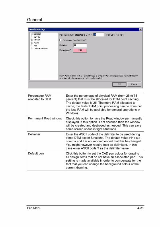
General
Percentage RAM allocated to DTM
Enter the percentage of physical RAM (from 25 to 75 percent) that must be allocated for DTM point caching. The default value is 25. The more RAM allocated to cache, the faster DTM point processing can be done but the less RAM will be available for general operations in Windows.
Permanent Road window Check this option to have the Road window permanently displayed. If this option is not checked then the window will be created and destroyed as needed. This can save some screen space in tight situations.
Delimiter Enter the ASCII code of the delimiter to be used during some DTM export functions. The default value (44) is a comma and it is not recommended that this be changed. You might however require tabs as delimiters. In this case enter ASCII code 9 as the delimiter value.
Default pen Click this button to set the CAD pen colour for drawing all design items that do not have an associated pen. This setting is made available in order to compensate for the fact that you can change the background colour of the current drawing.

4-32 Roads Reference
Southern Hemisphere
Short Axis labels Enter single character values to be used to label the relevant axes in dialogs, print-outs, etc. for Southern Hemisphere projects.
Long Axis labels Enter labels to be used to label the relevant axes in dialogs, print-outs, etc. for Southern Hemisphere projects.

File Menu 4-33
Northern Hemisphere
Short Axis labels Enter single character values to be used to label the relevant axes in dialogs, print-outs, etc. for Northern Hemisphere projects.
Long Axis labels Enter labels to be used to label the relevant axes in dialogs, print-outs, etc. for Northern Hemisphere projects.
4-34 Roads Reference
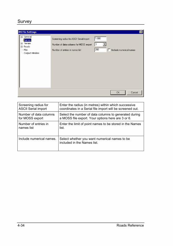
Survey
Screening radius for ASCII Serial import
Enter the radius (in metres) within which successive coordinates in a Serial file import will be screened out.
Number of data columns for MOSS export
Select the number of data columns to generated during a MOSS file export. Your options here are 3 or 6.
Number of entries in names list
Enter the limit of point names to be stored in the Names list.
Include numerical names.
Select whether you want numerical names to be included in the Names list.

File Menu 4-35
Terrain
Separator between degrees, minutes and seconds for printing
Enter the single character to be displayed between the degree, minute and second portions of bearings when printing. The default separator is a space.
Default point name suffix for Tache Reduction
Enter the single character default to be added as a suffix to point names during Tache Reduction.
Additional file extension for Tache files
Enter an extension to be used in addition to the standard DAT file extension when selecting Tache field books to load.
4 decimal places in Level Reduction
Check this option to have levels displayed to 4 decimal places rather than the standard 3 decimal places in Level Reduction.
Field number of orientation station name in Booker files
Enter the number of the field that contains the orientation station name in Booker tache files. This is normally 1 but files with the name in the eighth field have been found. Each field in a Booker file is separated by a tab with the first field being number 1.
Percentage of screen size for polygon auto-close snap
Enter the percentage of the current screen size to be used as the separation between starting and current indicated points in order to automatically close an indicated polygon.
Rotation angle about eye position for Line of Sight sweep
Enter the angle (in degrees) by which to increment rotation about the eye point when generating the visible boundary in Line of Sight calculations.
Display lines for terrace surface only during terrace selection
Check this option to display the lines of the selected terrace surface only when selecting a terrace. Line display for all other surfaces will automatically be switched off.
4-36 Roads Reference
Display autosuffix together with point name
Check this option to have any defined autosuffix appear as part of the point name in the screen display. It will not appear on a plot generation.
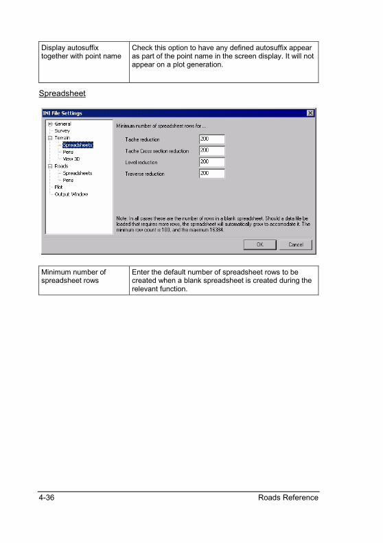
Spreadsheet
Minimum number of spreadsheet rows
Enter the default number of spreadsheet rows to be created when a blank spreadsheet is created during the relevant function.
File Menu 4-37
Pens
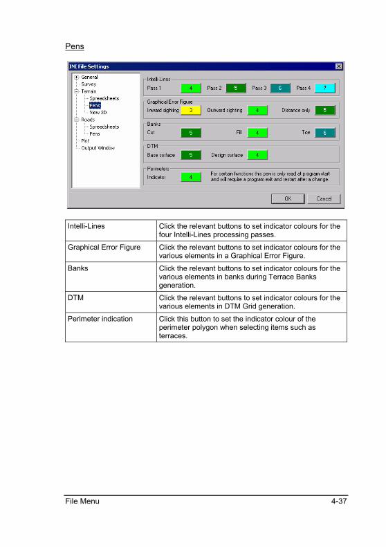
Intelli-Lines Click the relevant buttons to set indicator colours for the four Intelli-Lines processing passes.
Graphical Error Figure Click the relevant buttons to set indicator colours for the various elements in a Graphical Error Figure.
Banks Click the relevant buttons to set indicator colours for the various elements in banks during Terrace Banks generation.
DTM Click the relevant buttons to set indicator colours for the various elements in DTM Grid generation.
Perimeter indication Click this button to set the indicator colour of the perimeter polygon when selecting items such as terraces.

4-38 Roads Reference
View 3D
Depth buffer bits Select the number of bits available for depth buffering. Your options here are 16, 24 and 32. Your setting will depend on your video card and some experimentation might be required.
Colour depth bits Select the number of colour bits available. Your options here are 16,24 and 32. Your setting here should match the colour depth of your Windows Desktop for optimal results.
Field of view Enter the vertical field of view in degrees to generate the correct perspective view. In order to calculate the required field of view for your particular setting, measure the distance from your normal seated eye position to the screen and measure the height of the view area from top to bottom. Divide the second measurement by the first measurement, take the arc sin of the result, and round that result to the nearest degree.
Enable mouse dragging Uncheck this option to prevent mouse dragging within the 3D View from changing the view parameters. This should normally be left checked, but some video cards have problems with the rapid updates required.
Contour separation Enter the value (in metres) to be added to contour heights in order to prevent contours dissappearing underneath the 3D View.
Ignore video driver acceleration
Check this option to have the OpenGL acceleration capabilities of your graphics card ignored. This should normally be left unchecked, but some video cards have problems with the accelerated drivers.

File Menu 4-39
Roads
Maximum number of road files
Specify the maximum numbers of roads per project. The value must be between 100 and 150.
Use Interactive Roads Expert
Check this button to enable the Interactive Roads Expert. Before every roads operation the program will check if there are any operations that still needs to be done before the specified operation can commence. If there are then the Roads Expert will appear with the relative operations checked. Simply press OK to perform all the necessary operations and display the dialog for the specified operation.
Use TRH format when slaving Edge Control
Check this option to use TRH format when slaving Edge Control. If this option is checked then the distance given for the development length of the superelevation will be applied from the stage where the grade is 0 (flat) until it is fully developed. The initial portion where the normal crossfall is picked up (or reduced) to 0, is automatically calculated and added to the specified development length.
Use element entry for horizontal alignment instead of PIs and radii
Check this option to enter horizontal alignments by element (straights and curves) rather than by PI (with associated curve radius).
Use element entry for vertical alignment instead of VPIs
Check this option to enter vertical alignments by element (grades) rather than by VPI (with associated curve length).
Display VPI names when Check this option to have VPI names displayed during
4-40 Roads Reference
editing a vertical alignment
graphical editing of vertical alignments.
Extension to use when importing CARDS cross section files
Enter the default extension to be used when selecting data files for CARDS cross section import.
Text size for Horizontal PI Names and Warnings
When Editing the Horizontal alignment, the PI names and Design Criteria warnings will be displayed using this text size (points). A text size of 0 will cause the PI names and warnings not to be displayed.
PI Names and Warnings Warnings will be displayed using this text size (points). A text size of 0 will cause the PI names and warnings not to be displayed.
Box out
Check this option to box the Horizontal PI names and warnings. The text will be drawn within a rectangular frame, filled with the background colour.
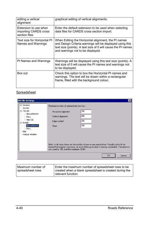
Spreadsheet
Maximum number of spreadsheet rows
Enter the maximum number of spreadsheet rows to be created when a blank spreadsheet is created during the relevant function.

File Menu 4-41
Pens
Horizontal alignment Click the relevant buttons to set indicator colours for the various elements.
Vertical alignment Click the relevant buttons to set indicator colours for the various elements.
Pipeline Click the relevant buttons to set indicator colours for the various elements.
Intersection Click the relevant buttons to set indicator colours for the various elements.
Template Editor Click the relevant buttons to set indicator colours for the various elements.
Layerworks Note: The Layerworks pen will be used to draw the layerwors in Graphical Edit mode as well.

4-42 Roads Reference
Plot
Number of lines plotted/labelled in a long section and cross section
Enter the maximum number of lines that can be generated when plotting a long- or cross section. The default is 20.
Interpolate long section level for 0 values
If this option is set then, when plotting longsections and a zero level is encountered for a chainage, the level at that chainage will be interpolated from the nearest chainages on either side that do have levels.
Split height labels into two at the decimal point
If this option is set, then when generating a plot with heights displayed, the height for a point will be shown as two distinct text entities separated at the decimal point. This is usefull for where the height is obscured by say a symbol inserted at the point and you wish to move the values apart for clarity.

File Menu 4-43
Output Window
Number of lines retained in memory
Enter the number of lines of output that should be retained at any time for the various output windows. This will be the last x number of lines that have been sent to the Output Window for display, enabling you to scroll back to see lines that have dissappeared off the top of the window.
Display/Print Font Enter the display/print font size (in points) and the position at which a right margin marker should be displayed in the Output Window.
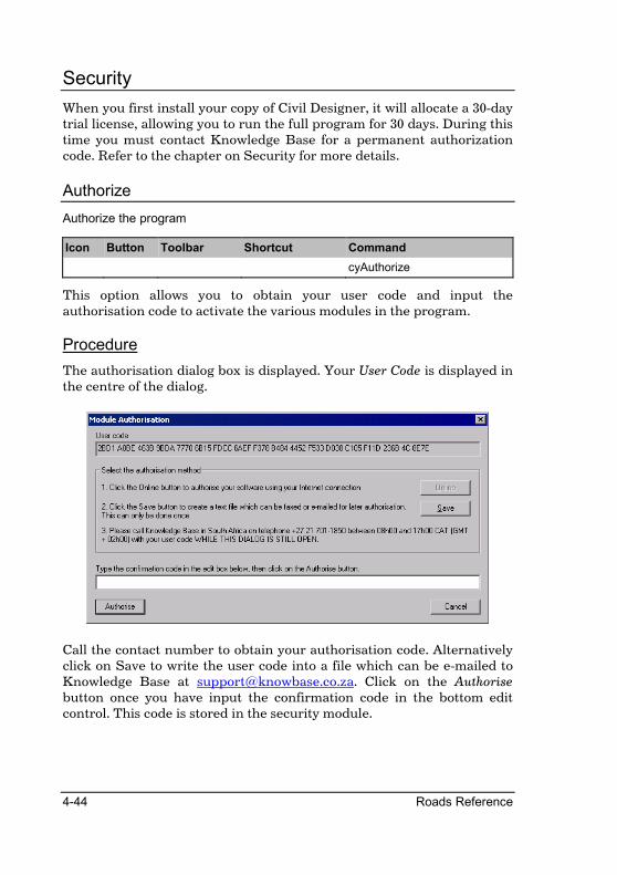
4-44 Roads Reference
Security
When you first install your copy of Civil Designer, it will allocate a 30-day trial license, allowing you to run the full program for 30 days. During this time you must contact Knowledge Base for a permanent authorization code. Refer to the chapter on Security for more details.
Authorize
Authorize the program
Icon Button Toolbar Shortcut Command
cyAuthorize
This option allows you to obtain your user code and input the authorisation code to activate the various modules in the program.
Procedure
The authorisation dialog box is displayed. Your User Code is displayed in the centre of the dialog.
Call the contact number to obtain your authorisation code. Alternatively click on Save to write the user code into a file which can be e-mailed to Knowledge Base at [email protected]. Click on the Authorise button once you have input the confirmation code in the bottom edit control. This code is stored in the security module.

File Menu 4-45
Check Network Dongles
Toggle network security on/off
Icon Button Toolbar Shortcut Command
CheckNetworkSecurity
This function switches the search for a network security module on or off.
Exit
Quit Civil Designer
Icon Button Toolbar Shortcut Command
quit
This function closes down Civil Designer.

4-46 Roads Reference
Notes:

Section Menu 5-1
Sections Menu
The Sections Menu contains functions that are used to edit and manipulate the road sections.

5-2 Roads Reference
Graphical Edit
Graphical editing of cross sectional data
Icon Button Toolbar Shortcut Command
RoadSectionGraphicalEdit
The graphical procedures are the primary functions for cross section editing. The advantages of graphical editing are the ability to edit several layers with reference to one another and that an instant visual verification of changes can be made.
Up to ten cross section layers may be displayed per chainage. The layers and pen colors for the cross sections must be set up in Layer Details under the Section menu. Although several layers are displayed, editing may only take place on the current Active Line that is also selected in the Layer Details dialog.
Points may be entered be clicking on the Insert icon on the toolbar, deleted by clicking on the Delete icon, edited by clicking on the Edit icon, or moved by clicking on the Move icon.
To move through the chainages in the road database, the following keys are used:
• PgDn to move to the next chainage 'down' the road.
• PgUp to move to the previous chainage 'up' the road.
• 'G' to go to a specified chainage that must be entered.
• ‘F’ to have the Design Centre window pan automatically to display the position of the current section.
Note that these keys are not case sensitive.
For the edit process, the following cursor control mode options are available:
• 'L' performs a line lock. The cursor jumps to the nearest line then tracks it.
• 'K' performs a slope lock. A percentage slope is entered and the cursor locks to that slope. Commonly used after a Jump to Nearest.
• 'U' provides an absolute or relative jump. For absolute jumps, the dialog box entry enables the cursor to be positioned at a precise offset and elevation. For relative jumps, the dialog box entry enables the cursor to be positioned by a precise offset and level difference from the present position. Commonly used after a Jump to Nearest.

Section Menu 5-3
• 'J' provides a jump to nearest. The same effect as a snap.
• 'P' allows the measurement of the area and perimeter of a defined polygon.
• 'I' allows the insertion of a section point as an intersection between two indicated lines.
Note that these keys are not case sensitive.
A popup menu can be displayed by right clicking on the Roads window. The following options are available from the popup menu:
Insert Point Insert a cross section point
Edit Point Edit a cross section point
Delete Point Delete a cross section point
Move point Move a cross section point
Layer Details Display the Layer details dialog
Polygon Area Calculate a polygon Area
Goto Chainage Goto a specified chainage
Line intersection Calculate a line intersection point
Measure Measure between two graphically indicated points
The cursor control modes work on all the currently displayed layers, although only the active layer selected under Layer Details may be edited.
On leaving the section by moving to another section, or quitting the routine, an option will be given to save or abandon the changes made. Saving the data results in the changes made being written to the road database while abandoning will result in any changes being ignored.
Procedure
The first cross section in the current road file is displayed in the Road window.

5-4 Roads Reference
Insert Point
Insert a new point in the active cross section
Icon Button Toolbar Shortcut Command
RoadSectionGraphicalInsertPoint
Inserts a new point in the current cross section. The current cross section is the line that has been set as Active in the Layer Details dialog.
Procedure
The following prompt is displayed:
Line 2: Indicate position to insert a point
Click on a position in the Road window and the indicated point is added to the current cross section with the current offset and elevation.
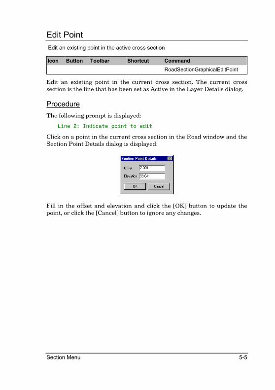
Section Menu 5-5
Edit Point
Edit an existing point in the active cross section
Icon Button Toolbar Shortcut Command
RoadSectionGraphicalEditPoint
Edit an existing point in the current cross section. The current cross section is the line that has been set as Active in the Layer Details dialog.
Procedure
The following prompt is displayed:
Line 2: Indicate point to edit
Click on a point in the current cross section in the Road window and the Section Point Details dialog is displayed.
Fill in the offset and elevation and click the [OK] button to update the point, or click the [Cancel] button to ignore any changes.

5-6 Roads Reference
Delete Point
Delete an existing point in the active cross section
Icon Button Toolbar Shortcut Command
RoadSectionGraphicalDeletePoint
Delete an existing point in the current cross section. The current cross section is the line that has been set as Active in the Layer Details dialog.
Procedure
The following prompt is displayed:
Line 2: Indicate point to delete
Click on a point in the current cross section in the Road window and the indicated point is removed from the current cross section.

Section Menu 5-7
Move Point
Move an existing point in the active cross section
Icon Button Toolbar Shortcut Command
RoadSectionGraphicalMovePoint
Move an existing point in the current cross section. The current cross section is the line that has been set as Active in the Layer Details dialog.
Procedure
The following prompt is displayed:
Line 2: Indicate point to move
Click on an existing point in the current cross section in the Road window and the following prompt is displayed:
Line 2: Indicate position for point
Click on a new position for the point and the current cross section is updated with the new position of the point.

5-8 Roads Reference
Polygon Area
Calculate the area and perimeter of an indicated polygon
Icon Button Toolbar Shortcut Command
RoadSectionGraphicalArea
This function calculates the area and perimeter of a polygon formed by indicating points on the displayed cross sections. The points indicated can be on any of the displayed layers.
Procedure
The following prompt is displayed:
Indicate start of polygon
Click on a point in the Road window and the following prompt is displayed:
Indicate point on polygon
Click on the next point that will form the polygon. You will continue to be prompted for the next point in the polygon until you select the point initially specified as starting the polygon.
The following message is displayed:
The Area displayed is the calculated area of the indicated polygon while the Perimeter displayed is the calculated perimeter of that polygon.

Section Menu 5-9
Line Intersection
Insert a new point in the active cross section at the intersection of two lines
Icon Button Toolbar Shortcut Command
RoadSectionGraphicalIntersection
Inserts a new point in the current cross section at the intersection of two lines formed from existing points. The current cross section is the line that has been set as Active in the Layer Details dialog.
Procedure
The following prompt is displayed:
Indicate first intersecting line
Click on a line between two points on one of the surfaces and the following prompt is displayed:
Indicate second intersecting line
Click on a line between two points on one of the surfaces and a new point is inserted into the current cross section at the calculated intersection of the two lines.

5-10 Roads Reference
Goto Chainage
Display the cross sections for a selected chainage
Icon Button Toolbar Shortcut Command
RoadSectionGraphicalGoTo
This function allows you to select the chainage for which the cross sections should be displayed.
Procedure
If the cross sections of the current chainage have been edited, the following message is displayed:
Click the [Yes] button to save the changes made to the cross sections, or click the [No] button to ignore any changes.
The Goto Chainage dialog is displayed.
Fill in the relevant data and click the [OK] button to move to the new chainage.
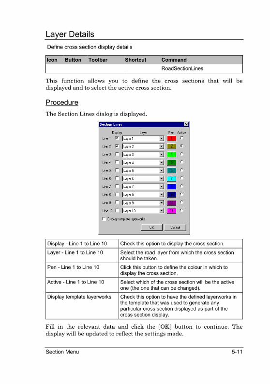
Section Menu 5-11
Layer Details
Define cross section display details
Icon Button Toolbar Shortcut Command
RoadSectionLines
This function allows you to define the cross sections that will be displayed and to select the active cross section.
Procedure
The Section Lines dialog is displayed.
Display - Line 1 to Line 10 Check this option to display the cross section.
Layer - Line 1 to Line 10 Select the road layer from which the cross section should be taken.
Pen - Line 1 to Line 10 Click this button to define the colour in which to display the cross section.
Active - Line 1 to Line 10 Select which of the cross section will be the active one (the one that can be changed).
Display template layerworks Check this option to have the defined layerworks in the template that was used to generate any particular cross section displayed as part of the cross section display.
Fill in the relevant data and click the [OK] button to continue. The display will be updated to reflect the settings made.

5-12 Roads Reference
List Sections
List cross section details to the selected device
Icon Button Toolbar Shortcut Command
RoadSectionList
This function allows you to list the offset and elevation data from the cross section on any layer.
Procedure
The Listing Details dialog is displayed.
Start chainage Enter the first chainage of the range of chainages to process.
Stop chainage Enter the last chainage of the range of chainages to process.
List type... Select either the Normal , Double or the Compacted option.
Normal Listing - This option lists a single layer with each offset and elevation pair of the cross section listed on a new line.
Double Listing - This enables the normal cross section listing of two different layers side by side. It is particularly applicable to situations where the two layers that were used to create a volume need to be inspected.
Compacted Listing - This option lists a single layer, but packs a number of offset and elevation pairs of the cross section per line. It is mostly useful for archiving redundant data.
Layer Select the layer from which the cross section to be listed should be extracted.
Fill in the relevant data and click the [OK] button to continue.

Section Menu 5-13
Enter/Edit Sections
Manually enter a new or edit an existing cross section
Icon Button Toolbar Shortcut Command
RoadSectionEdit
This function allows you to enter new sections or edit existing sections by typing in the offset and elevation values in a grid.
The ID number and Code of the point may also be edited here. The ID number can be used during cross section plotting to identify certain points of interest. The Code entry is used to mark shoulder and median points on road layers. Shoulder points should be marked with the code '100' (negative for left of CL, positive for right), and median points (applicable only to dual carriageway roads) should be marked with the code '101' (negative for left of CL, positive for right).
Procedure
The Layer Selection dialog is displayed.
Select the layer you wish to work with and click the [OK] button to continue. The Editing Details dialog is displayed.

5-14 Roads Reference
If at any point a new cross section needs to be read and the current cross section has been changed but not yet saved, the following message is displayed:
Click the [Yes] button to save the changes to the current cross section, or click the [No] button to abandon any changes made.

Section Menu 5-15
Interpolate
Interpolate a new elevation on an existing cross section
Icon Button Toolbar Shortcut Command
RoadSectionElevationInterpolate
This function is used to interpolate an elevation on an existing cross section. It is useful for extracting long sections or adding points at a certain offset on the cross section. Inserting retaining walls would be a typical example. Obviously, PLC codes cannot be used for this routine.
Procedure
The Process Details dialog is displayed.
Start chainage Enter the first chainage of the range of chainages to process.
Stop chainage Enter the last chainage of the range of chainages to process.
Process layer Select the layer from which existing cross section data should be read.
Store to layer Check this option and select the layer to which the altered cross section should be stored. If this option is not checked then the changes are only listed and not stored.
Define details by... Select the Offset from centreline option to specify the details using offsets, or select the Point location code option to define details using PLC's. The Point location code option is only available for some functions.

5-16 Roads Reference
Enter details for sections... Select either the Individually option in order to provide details for each chainage in the range, or select the Whole chainage range option in order to apply one set of details to all the chainages in the range.
Surface action Select either the Add points option to add new points to the cross section, the Overwrite option to overwrite any existing points in the cross section, or the Merge option to carry out a simultaneous delete and add of points in the cross section. The Merge option is only available for some functions.
Verify section save Check this option to be asked if each altered section must be saved. If this option is not checked then each altered section is saved automatically.
Fill in the relevant data and click the [OK] button to continue.
The Overwrite option will delete all existing points in the Store to layer cross section before processing. Please be certain that this is what you intend to happen before selecting this option.
The Elevation Interpolation dialog is displayed.
Offset from centerline Enter the offset at which the elevation should be interpolated. Offsets to the left of the centerline should be entered as a negative value.
Add Button Add the current value of the "Offset from centerline" edit box to the Offset list.
Remove Button Remove the selected entry from the Offset List.
Clear List Clear the contents of the Offset List.

Section Menu 5-17
The program will interpolate elevations for each of the offsets present in the "Offset List". If the Offset List is empty, the program will interpolate a height for the offset entered into the "Offset from centerline" edit box.
Enter the offset from the centerline to interpolate elevations from. Enter either a single offset, or a range of offsets using a comma-delimited string.
The Output Manager dialog is displayed in order for you to set output options. Click the [OK] button to accept the settings.
If you selected the Individually option for Enter details for sections in the Process Details dialog, then the Elevation Interpolation dialog is displayed for each chainage in the range, giving you the opportunity to alter the specified offset for each chainage.
Click the [OK] button to continue, or click the [Cancel] button to end the function.
If you checked the Verify section save option then after each cross section is processed the following message is displayed:
Click the [Yes] button to save the updated cross section, or click the [No] button to retain the existing cross section.

5-18 Roads Reference
Remove Points
Delete points on an existing cross section
Icon Button Toolbar Shortcut Command
RoadSectionRemovePoints
This function is used to remove some or all of the points from a cross sectional layer.
Once the left and right limits for the removal (by offset or PLC code) have been specified, all points within this range will be removed, either for the specific chainage or for the chainage range specified.
If you want to remove a specific point from a layer then you must select the store option and select the layer to which you wish to store as the layer that is being processed. You must also select the Overwrite option for storing points.
Procedure
The Process Details dialog is displayed.
Start chainage Enter the first chainage of the range of chainages to process.
Stop chainage Enter the last chainage of the range of chainages to process.
Process layer Select the layer from which existing cross section data should be read.

Section Menu 5-19
Store to layer Check this option and select the layer to which the altered cross section should be stored. If this option is not checked then the changes are only listed and not stored.
Define details by... Select the Offset from centreline option to specify the details using offsets, or select the Point location code option to define details using PLC's. The Point location code option is only available for some functions.
Enter details for sections... Select either the Individually option in order to provide details for each chainage in the range, or select the Whole chainage range option in order to apply one set of details to all the chainages in the range.
Surface action Select either the Add points option to add new points to the cross section, the Overwrite option to overwrite any existing points in the cross section, or the Merge option to carry out a simultaneous delete and add of points in the cross section. The Merge option is only available for some functions.
Verify section save Check this option to be asked if each altered section must be saved. If this option is not checked then each altered section is saved automatically.
Fill in the relevant data and click the [OK] button to continue. The Section Point Deletion dialog is displayed.
Delete between offsets Only available if processing by offsets.
Enter the offsets between which points should be deleted. If you wish to delete one particular point by offset, say at 1.5, then enter the offsets as slightly smaller than and slightly larger than the desired value.
Using our example you would enter the offsets as 1.49 and 1.51. This will overcome the effect of floating point rounding where a point such as 1.5 is actually stored as 1.499999.
Offsets to the left of the centreline should be entered as negative values.

5-20 Roads Reference
Delete between point codes Only available if processing by point codes.
Enter the PLC's between which points should be deleted. PLC's are exact codes so floating point rounding plays no part.
Points to the left of the centreline should be entered as negative values.
Fill in the relevant details and click the [OK] button to continue.
The Output Manager dialog is displayed in order for you to set output options. Click the [OK] button to accept the settings.
If you selected the Individually option for Enter details for sections... in the Process Details dialog, then the Section Point Deletion dialog is displayed for each chainage in the range, giving you the opportunity to alter the specified offset for each chainage.
Click the [OK] button to continue, or click the [Cancel] button to end the function.
If you checked the Verify section save option then after each cross section is processed the following message is displayed:
Click the [Yes] button to save the updated cross section, or click the [No] button to retain the existing cross section.

Section Menu 5-21
Transfer Points
Transfer points between cross sections
Icon Button Toolbar Shortcut Command
RoadSectionTransferPoints
This function is used to transfer points from one layer to another. Either the whole section or a portion of it can be transferred and the moved data can (optionally) replace just that portion of the old section leaving the remainder of the original section intact. The most common usage is to move all or part of a 'This Month' layer into a 'Last Month' layer for construction monitoring.
If the option to Merge data is chosen, then, unlike Adding data to the layer, this option will cause the incoming data to replace any existing points that are within the specified offsets. Data points that are outside the offsets will be retained. It is a bit like a simultaneous delete and then add. It should not be confused with the Overwrite option that will replace the entire layer with the incoming data.
Procedure
The Process Details dialog is displayed.
Start chainage Enter the first chainage of the range of chainages to process.
Stop chainage Enter the last chainage of the range of chainages to process.
Process layer Select the layer from which existing cross section data should be read.
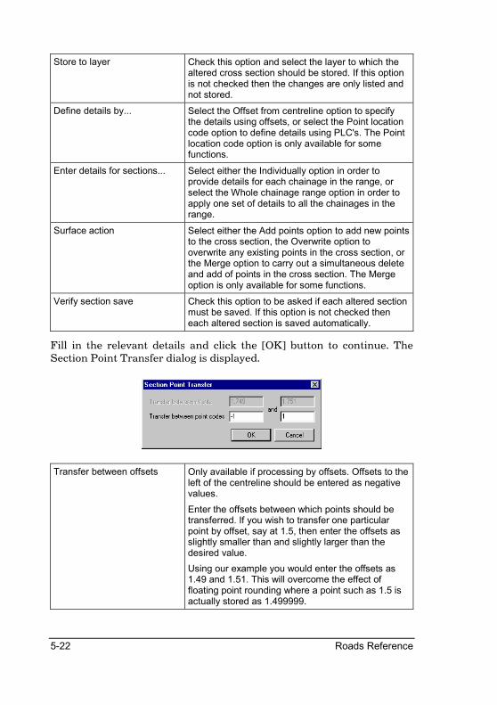
5-22 Roads Reference
Store to layer Check this option and select the layer to which the altered cross section should be stored. If this option is not checked then the changes are only listed and not stored.
Define details by... Select the Offset from centreline option to specify the details using offsets, or select the Point location code option to define details using PLC's. The Point location code option is only available for some functions.
Enter details for sections... Select either the Individually option in order to provide details for each chainage in the range, or select the Whole chainage range option in order to apply one set of details to all the chainages in the range.
Surface action Select either the Add points option to add new points to the cross section, the Overwrite option to overwrite any existing points in the cross section, or the Merge option to carry out a simultaneous delete and add of points in the cross section. The Merge option is only available for some functions.
Verify section save Check this option to be asked if each altered section must be saved. If this option is not checked then each altered section is saved automatically.
Fill in the relevant details and click the [OK] button to continue. The Section Point Transfer dialog is displayed.
Transfer between offsets Only available if processing by offsets. Offsets to the left of the centreline should be entered as negative values.
Enter the offsets between which points should be transferred. If you wish to transfer one particular point by offset, say at 1.5, then enter the offsets as slightly smaller than and slightly larger than the desired value.
Using our example you would enter the offsets as 1.49 and 1.51. This will overcome the effect of floating point rounding where a point such as 1.5 is actually stored as 1.499999.

Section Menu 5-23
Transfer between point codes Only available if processing by point codes. Points to the left of the centreline should be entered as negative values.
Enter the PLC's between which points should be transferred. PLC's are exact codes so floating point rounding plays no part.
Fill in the relevant details and click the [OK] button to continue.
The Output Manager dialog is displayed in order for you to set output options. Click the [OK] button to accept the settings.
If you selected the Individually option for Enter details for sections... in the Process Details dialog, then the Section Point Transfer dialog is displayed for each chainage in the range, giving you the opportunity to alter the specified offset for each chainage.
Click the [OK] button to continue, or click the [Cancel] button to end the function.
If you checked the Verify section save option then after each cross section is processed the following message is displayed:
Click the [Yes] button to save the updated cross section, or click the [No] button to retain the existing cross section.

5-24 Roads Reference
Absolute Change
Apply constants to an existing cross section
Icon Button Toolbar Shortcut Command
RoadSectionAbsoluteChange
This function is used to move all, some, or even single points on a cross sectional layer vertically or horizontally by a constant amount. A typical use would be to deepen a feature like a drain bottom by a constant (or increasing) amount. It is also possible to set points on the cross section to a specific value. A typical application for this would be to set the top of a retaining wall to a fixed elevation.
The movement to be applied can also be controlled by a lineal interpolation whereby one shift is set for the start chainage and another for the end chainage and the movement spread evenly over the range.
This function should be considered in conjunction with the Expand/Shrink facility that offers powerful editing in the horizontal plane.
Procedure
The Process Details dialog is displayed.
Start chainage Enter the first chainage of the range of chainages to process.
Stop chainage Enter the last chainage of the range of chainages to process.
Process layer Select the layer from which existing cross section data should be read.

Section Menu 5-25
Store to layer Check this option and select the layer to which the altered cross section should be stored. If this option is not checked then the changes are only listed and not stored.
Define details by... Select the Offset from centreline option to specify the details using offsets, or select the Point location code option to define details using PLC's. The Point location code option is only available for some functions.
Enter details for sections... Select either the Individually option in order to provide details for each chainage in the range, or select the Whole chainage range option in order to apply one set of details to all the chainages in the range.
Surface action Select either the Add points option to add new points to the cross section, the Overwrite option to overwrite any existing points in the cross section, or the Merge option to carry out a simultaneous delete and add of points in the cross section. The Merge option is only available for some functions.
Verify section save Check this option to be asked if each altered section must be saved. If this option is not checked then each altered section is saved automatically.
Fill in the relevant data and click the [OK] button to continue. The Absolute Change dialog is displayed.
Type of change... Select either the Add value as constant option to add the entered value to the existing value, or the Set to specific value option to change the existing value to the entered value.

5-26 Roads Reference
Apply change to... Select either the Offset option to make the changes to the point offset, or the Elevation option to make the changes to the point elevation.
Offset limits - Left and Right Enter the limits of the points to process as offsets. This option is only available if the Offset from centreline option was chosen for Define details by... in the Process Details dialog.
Relative point codes - Left and Right
Enter the limits of the points to process as PLC's. This option is only available if the Point location code option was chosen for Define details by... in the Process Details dialog.
Value to apply - Start and End
Enter the value to be applied at the start and end of the selected chainage range. If different values are entered for start and end then the start value is applied to the first chainage in the range, the end value is applied to the final chainage in the range, and the value to be applied to the intermediate chainages is calculated by linear interpolation over the selected range.
Fill in the relevant details and click the [OK] button to continue.
The Output Manager dialog is displayed in order for you to set output options. Click the [OK] button to accept the settings.
If you selected the Individually option for Enter details for sections... in the Process Details dialog, then the Absolute Change dialog is displayed for each chainage in the range, giving you the opportunity to alter the details for each chainage. Click the [OK] button to continue, or click the [Cancel] button to end the function.
If you checked the Verify section save option in the Process Details dialog, then after each cross section is processed the following message is displayed:
Click the [Yes] button to save the updated cross section, or click the [No] button to retain the existing cross section.
Section Menu 5-27
Expand/Shrink
Expand or shrink an existing cross section
Icon Button Toolbar Shortcut Command
RoadSectionExpandShrink
This function is used to expand or shrink cross sections by moving a whole set of points horizontally left or right of a certain 'target' offset. The movement can be horizontal or 'on a grade'. It is typically used to widen carriageways, expand kerbs, allow for bus ranks, create bell mouths, transition in and out of dual carriageway splits, introduce drains etc.
The routine is only applicable to horizontal shifts. For vertical shifts, refer to the Absolute Change routine.
If the details are to be applied to the entire specified chainage range, the amount to insert at both the start and stop chainages must be entered. The actual value can be either an expansion (positive value) or shrinkage (negative value) or nothing. For each intervening section, the amount to insert will be calculated by lineal interpolation between the start and stop chainages.
End
Start
Expansion (e.g. 0 to 2m) Shrinkage (e.g. 0 to -2m)
If details are to be applied individually then only the start insertion is available and each chainage may be individually set.

5-28 Roads Reference
A 'target offset' is identified from which the movement will be based. This will be an offset relative to the CL. The points lying either to the left or to the right of this 'target offset' may be moved and they can be moved horizontally or along the grade of the section at the 'target offset'.
By default all the points to the left or right of the target offset are moved. However, if the Move within radius of target offset option is selected, a value for the radius has to be entered and only points that fall within this radius of the target offset will be moved.
If you move points horizontally the points are simply shifted to the left or right as shown below.
TargetOffset
CL
Horizontal move of points to left
If you move point on a grade the points are moved at the grade just before the target offset. In the example below the carriageway grade is used to move the points.
TargetOffset
CL
‘On grade’ move of points to right
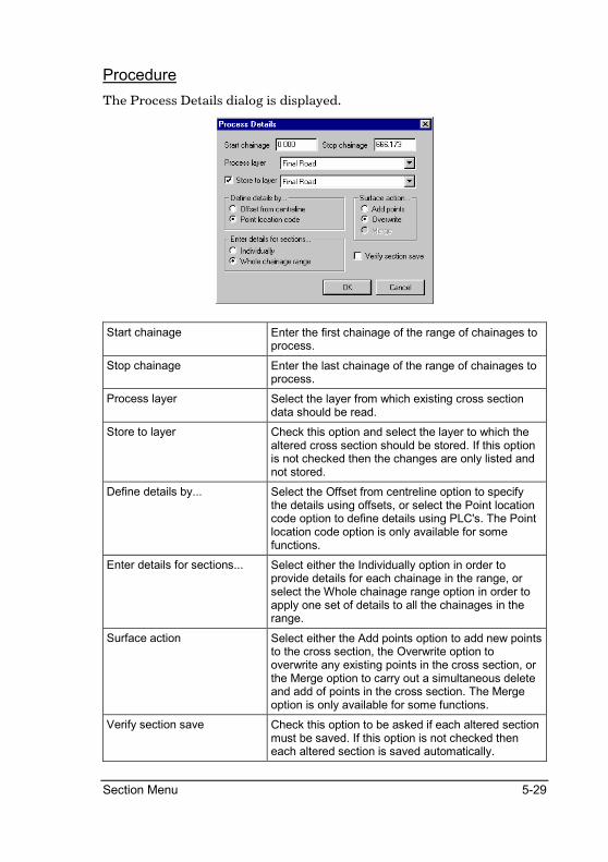
Section Menu 5-29
Procedure
The Process Details dialog is displayed.
Start chainage Enter the first chainage of the range of chainages to process.
Stop chainage Enter the last chainage of the range of chainages to process.
Process layer Select the layer from which existing cross section data should be read.
Store to layer Check this option and select the layer to which the altered cross section should be stored. If this option is not checked then the changes are only listed and not stored.
Define details by... Select the Offset from centreline option to specify the details using offsets, or select the Point location code option to define details using PLC's. The Point location code option is only available for some functions.
Enter details for sections... Select either the Individually option in order to provide details for each chainage in the range, or select the Whole chainage range option in order to apply one set of details to all the chainages in the range.
Surface action Select either the Add points option to add new points to the cross section, the Overwrite option to overwrite any existing points in the cross section, or the Merge option to carry out a simultaneous delete and add of points in the cross section. The Merge option is only available for some functions.
Verify section save Check this option to be asked if each altered section must be saved. If this option is not checked then each altered section is saved automatically.

5-30 Roads Reference
Fill in the relevant details and click the [OK] button to continue. The Expand/Shrink dialog is displayed.
Target offset for insertion Enter the offset at which the expand/shrink must take place.
Amount to insert - Start and End
Enter the start and end value of the insertion that should take place. If start and end have different values then the start value is applied to the first chainage in the selected chainage range, the end value is applied to the last chainage in the selected chainage range, and the intermediate values have a linearly interpolated value applied.
Move points... Select either the Left of target option to move points located to the left of the target offset, or the Right of target option to move points located to the right of the target offset.
Move points on... Select either the Grade option to move points at the grade calculated at the target offset, or the Horizontally option to move points horizontally.
Move within radius of target offset
Check this option and enter a radius to restrict alteration to points located within the specified radius of the target offset.
Fill in the relevant details and click the [OK] button to continue.
The Output Manager dialog is displayed in order for you to set output options. Click the [OK] button to accept the settings.
If you selected the Individually option for Enter details for sections... in the Process Details dialog, then the Expand/Shrink dialog is displayed for each chainage in the range, giving you the opportunity to alter the specified details for each chainage.

Section Menu 5-31
Click the [OK] button to continue, or click the [Cancel] button to end the function.
If you checked the Verify section save option then after each cross section is processed the following message is displayed:
Click the [Yes] button to save the updated cross section, or click the [No] button to retain the existing cross section.

5-32 Roads Reference
Layerwork Box
Create layerworks by deduction from an existing cross section
Icon Button Toolbar Shortcut Command
RoadSectionBoxDeduct
This function is used to create simple earthwork cross sections from an existing final road layer by deducting a layer of a certain depth between specified offsets. In a cut situation, this layer will normally have vertical sides resulting in an earthwork 'box'.
It is also possible to specify that the bottom of the 'box' be extended to attempt to intersect with the left side, the right side or both batters of the layer. This caters specifically for layer works in fills that are not boxed. If an intersection cannot be achieved, a normal box will be generated. For dual carriageway roads, the routine will normally have to be performed twice, once for each carriageway.
The depth of the box to deduct must be entered as well as specifying whether the base of the box should attempt to intersect with the left and/or right batters of the section. There is an option to either ignore or add the points beyond the limits of the created box.
Ignoring the points will yield a section that is confined to the box bottom and walls alone, and is the most common choice if only a visual representation or plot of the section is required.
Adding the points will result in all the data beyond the box limits being included in the new section. This includes the batters if present and this option would be used if areas and volumes were required from the resulting cross section.
It should be noted that there is nothing in the routine that cannot be handled as well or better by setting up a suitable template for that subsurface layer.

Section Menu 5-33
Procedure
The Process Details dialog is displayed.
Start chainage Enter the first chainage of the range of chainages to process.
Stop chainage Enter the last chainage of the range of chainages to process.
Process layer Select the layer from which existing cross section data should be read.
Store to layer Check this option and select the layer to which the altered cross section should be stored. If this option is not checked then the changes are only listed and not stored.
Define details by... Select the Offset from centreline option to specify the details using offsets, or select the Point location code option to define details using PLC's. The Point location code option is only available for some functions.
Enter details for sections... Select either the Individually option in order to provide details for each chainage in the range, or select the Whole chainage range option in order to apply one set of details to all the chainages in the range.
Surface action Select either the Add points option to add new points to the cross section, the Overwrite option to overwrite any existing points in the cross section, or the Merge option to carry out a simultaneous delete and add of points in the cross section. The Merge option is only available for some functions.
Verify section save Check this option to be asked if each altered section must be saved. If this option is not checked then each altered section is saved automatically.

5-34 Roads Reference
Fill in the relevant data and click the [OK] button to continue.
The Layerwork Box Deduction dialog is displayed.
Box deduction offsets - Left and Right
Enter the left and right offsets between which the box should be deducted. Offsets to the left of the centreline should be entered as negative values. Only available if entering details by offset.
Box deduction point codes - Left and Right
Enter the left and right PLC's between which the box should be deducted. Points to the left of the centreline should be entered as negative values. Only available if entering details by point codes.
Box depth to deduct Enter the depth that should be deducted from the cross section to form the box.
Try to intersect with batters - Left and Right
Check these options to have the routine try to intercept with the batter slopes on the respective sides. If an intersection cannot be calculated then that side will be taken vertically to an intersection with the original cross section.
Include points outside box Check this option to have points falling outside the box copied from the original cross section to the new cross section.
Fill in the relevant data and click the [OK] button to continue.
The Output Manager dialog is displayed in order for you to set output options. Click the [OK] button to accept the settings.
If you selected the Individually option for Enter details for sections... in the Process Details dialog, then the Layerwork Box Deduction dialog is displayed for each chainage in the range, giving you the opportunity to alter the specified offset for each chainage.
Click the [OK] button to continue, or click the [Cancel] button to end the function.

Section Menu 5-35
If you checked the Verify section save option then after each cross section is processed the following message is displayed:
Click the [Yes] button to save the updated cross section, or click the [No] button to retain the existing cross section.

5-36 Roads Reference
Layer Deduction
Create a new cross section by deduction from an existing cross section
Icon Button Toolbar Shortcut Command
RoadSectionLayerDeduct
Like Layerwork Box, this function is used to create simple earthwork cross sections from an existing final road layer by deducting a layer of a certain depth between specified offsets.
The Offset to extract the crossfall from is the target distance that will dictate the slope of the layer. Whatever the slope is at this offset will be adopted for the layer.
The Offset for Cut Off dictates how far the layer will run. It may be an offset or a PLC code and the layer will extend this far unless either of the Snip at Intersection of Cut/Fill boxes are checked. If they are, the layer will stop short of the Cut-Off offset if it crosses a cut or fill batter slope.
The Extend Layer from Cut-Off option will be available only if the Offset for Cut-Off was defined by a PLC code. If a figure is entered here, the layer will be extended by that amount beyond the point defined by the offset code value. This is a "forced" extension and will override any Snip instruction.
The box to be deducted will follow the same crossfall as the final road layer. Thus, the crossfall between the points where the box is to be extracted will vary if the crossfall of the final road layer varies.
Procedure
The Process Details dialog is displayed.

Section Menu 5-37
Fill in the relevant data and click the [OK] button to continue. The Layer Deduction dialog is displayed.
Extract crossfalls at offset - Left and Right
Enter the left and right offset of the positions at which to calculate crossfalls. Points to the left of the centreline should be entered as negative values.
Offsets for cutoff - Left and Right
Enter the offset left and right at which the layer should end. Only available if entering data by offset. Points to the left of the centreline should be entered as negative values.
Point codes for cutoff offset - Left and Right
Enter the left and right PLC's at which the layer should end. Only available if entering data by point codes. Points to the left of the centreline should be entered as negative values.
Extend layer from cutoff by - Left and Right
Enter the extra length that should be added after the offset. Only available if entering data by point codes.
Layer depth to deduct Enter the depth below the original cross section at which the new cross section should be created.
Snip at batter intersection in FILL
Check this option to have the layer stop at the batter intersection if the full layer has not yet been created.
Snip at batter base in CUT Check this option to have the layer stop at the base of the batter slope if the full layer has not yet been created.
Fill in the relevant data and click the [OK] button to continue. The Output Manager dialog is displayed in order for you to set output options. Click the [OK] button to accept the settings.
If you selected the Individually option for Enter details for sections... in the Process Details dialog, then the Layer Deduction dialog is displayed for each chainage in the range, giving you the opportunity to alter the specified offset for each chainage.

5-38 Roads Reference
Click the [OK] button to continue, or click the [Cancel] button to end the function.
If you checked the Verify section save option then after each cross section is processed the following message is displayed:
Click the [Yes] button to save the updated cross section, or click the [No] button to retain the existing cross section.
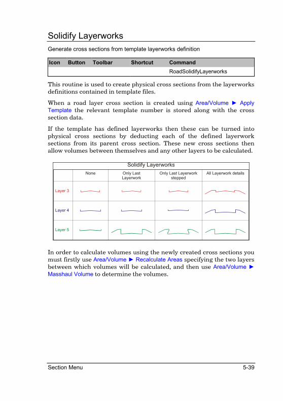
Section Menu 5-39
Solidify Layerworks
Generate cross sections from template layerworks definition
Icon Button Toolbar Shortcut Command
RoadSolidifyLayerworks
This routine is used to create physical cross sections from the layerworks definitions contained in template files.
When a road layer cross section is created using Area/Volume ► Apply
Template the relevant template number is stored along with the cross section data.
If the template has defined layerworks then these can be turned into physical cross sections by deducting each of the defined layerwork sections from its parent cross section. These new cross sections then allow volumes between themselves and any other layers to be calculated.
None Only LastLayerwork
Only Last Layerworkstepped
All Layerwork details
Layer 3
Layer 4
Layer 5
Solidify Layerworks
In order to calculate volumes using the newly created cross sections you must firstly use Area/Volume ► Recalculate Areas specifying the two layers between which volumes will be calculated, and then use Area/Volume ►
Masshaul Volume to determine the volumes.

5-40 Roads Reference
Procedure
The Solidify Layerworks dialog is displayed.
Start chainage Enter the first chainage in the range of chainages to process.
Stop chainage Enter the last chainage in the range of chainages to process.
Batter layer Select the layer that was generated using a template.
Initial destination layer Select the first layer on which to create generated cross sections. This layer will be used for the first layerwork definition. Subsequent layers will be used for subsequent layerwork definitions. For example, if you specify Layer 3 as the initial layer and there are three layers in the layerworks definition, then layers 3, 4, and 5 will contain the generated cross sections.
Include outside points from Batter layer for:
This option is used to include points in the batter layer cross section that lie outside the layerworks in the generated layer. See the illustration below.
Step in Fill Only
This option is only available if "Only last layerwork detail - stepped" is checked. If this option is checked then the layerworks will only be stepped when in fill. In cut situations a box cut, with a width equal to the first layerwork in cut, will be created.

Section Menu 5-41
Try to intersect with batters: Left and/or right
This option is not available if the "None" option is checked. If one of these options are checked you must specify a ground layer. Check these options to have the routine try to intercept with the batter slopes on the respective sides.
This routine will overwrite data in existing layers without warning. You will be warned if the number of the initial destination layer is lower than that of the batter layer as the possibility of overwriting the batter layer is then very real. Other than that, no warning is given.
Fill in the relevant data and click the [OK] button to continue.
The Output Manager dialog is displayed in order for you to set output options. Click the [OK] button to accept the settings.

5-42 Roads Reference
Notes:

Alignment Menu 6-1
Alignment Menu
The Alignment Menu allows you to define and modify the horizontal and vertical alignment of your road as well as the carriageway width, crossfall and super-elevation.

6-2 Roads Reference
Horizontal
These functions are used to calculate the coordinates of chainage points along a horizontal alignment that is defined in terms of known horizontal points of intersection (PI's) and circular curve radii. The coordinates are added to the chainage records of the cross section database associated with the active road.
If design data has been changed but fresh coordinates were not regenerated, a warning message will remind you to generate this data.
Several of the Horizontal Alignment menu items produce output that may either be printed to a printer or displayed on the screen. To read your output on the screen, make sure the Output window is open.

Alignment Menu 6-3
Edit Alignment
Edit horizontal alignment
Icon Button Toolbar Shortcut Command
RoadHorizontalEditAlignment
This function is used to enter a new horizontal alignment or to edit an existing alignment.
The horizontal alignment is stored in ASCII format in the 'design' file of the active road file and may be entered with the spreadsheet in this function or a text editor.
The alignment requires that the names of the start point, the horizontal PI's and the end point be entered. The radius of the horizontal curve at each PI must also be entered. A radius of 0 is calculated as a kink.
The value entered in the Radius column for the start point is not seen as a radius but is rather the start chainage of the alignment.
The horizontal curves may also have transition curves into and/or out of each curve specified. The TrIn and TrOut columns are used to specify the length of the transition curve, which is calculated as an Euler spiral. Transition lengths are usually equal on either side of the circular portion but there is no need to conform to this.
In order to correctly orient the alignment the coordinates of the start point, PI's and end point must be entered. If 0 is entered for both coordinate values, the current terrain file will be searched for a point of the same name and, if found, its coordinates will be entered automatically. If such a point is not found then you will be asked for the correct coordinates.
An optional offset from the actual centreline for each point may be entered. This is normally used in cases where the alignment points are not along the centreline of the road but rather at some other point such as the left or right kerb line. Offsets to the left of the alignment are entered as negative numbers, and those to the right as positive numbers. When the alignment is stored or calculated in any way, these offsets are used to determine the correct position of the points along the centreline.
Finally, a curve number may be entered. Leaving this set to 0 will allow this routine to number the points by their position in their alignment. You can however overwrite any or all of the curve numbers if you wish.

6-4 Roads Reference
Graphical Insert
Graphical PI insertion
Icon Button Toolbar Shortcut Command
RoadHorizontalGraphicalInsert
This routine works in conjunction with the horizontal alignment spreadsheet to allow you to graphically indicate PI positions.
You will probably need to minimize the spreadsheet window during this function in order to see the horizontal alignment that is displayed in the Design Centre window.
Procedure
The following prompt is displayed:
Indicate position for new PI
Click on a position in the Design Centre window and the Insert Details dialog is displayed.
PI Name Enter the PI Name
Insert as first PI Select this option to have the new PI inserted at the beginning of the current alignment.
Insert as PI number Select this option and enter a PI number to have the new PI inserted at that position in the current alignment.
Insert as last PI Select this option to have the new PI inserted at the end of the current alignment.
Fill in the relevant data and click on the [OK] button to continue.

Alignment Menu 6-5
Graphical Delete
Graphical PI deletion
Icon Button Toolbar Shortcut Command
RoadHorizontalGraphicalDelete
This routine works in conjunction with the horizontal alignment spreadsheet to allow you to graphically indicate PI's to be deleted.
You will probably need to minimize the spreadsheet window during this function in order to see the horizontal alignment that is displayed in the Design Centre window.
Procedure
The following prompt is displayed:
Indicate PI to delete
Click on a PI in the Design Centre window and the PI is then removed from the alignment.

6-6 Roads Reference
Graphical Edit
Graphical PI editing
Icon Button Toolbar Shortcut Command
RoadHorizontalGraphicalEdit
This routine works in conjunction with the horizontal alignment spreadsheet to allow you to graphically indicate PI's to be edited.
You will probably need to minimize the spreadsheet window during this function in order to see the horizontal alignment that is displayed in the Design Centre window.
Procedure
The following prompt is displayed:
Indicate PI to edit
Click on a PI in the Design Centre window and the Horizontal PI Details dialog is displayed.
Fill in the relevant data and click the [OK] button to continue.

Alignment Menu 6-7
Graphical Move
Graphical PI moving
Icon Button Toolbar Shortcut Command
RoadHorizontalGraphicalMove
This routine works in conjunction with the horizontal alignment spreadsheet to allow you to graphically indicate new positions for existing PI's. You can also move the BC and EC positions causing the radius to be recalculated.
You will probably need to minimize the spreadsheet window during this function in order to see the horizontal alignment that is displayed in the Design Centre window.
Procedure
The following prompt is displayed:
Indicate PI or EC/BC to move
Click on a PI in the Design Centre window and the following prompt is displayed:
Indicate new position for PI
Click on a position in the Design Centre window and the coordinates of the PI are updated to reflect the new position. The new PI position is displayed on the screen as the mouse is moved. Right click during the second part of the procedure to cancel the move.

6-8 Roads Reference
Fit Curve
Fit curve through fixed point
Icon Button Toolbar Shortcut Command
RoadHorizontalFitCurve
This function is used to fit a curve through a particular point. The straight on either side of the curve must be known; therefore an initial provisional alignment is necessary. If matching a new design to an existing road the calculation will commonly be run several times to several points and a mean or 'best fit' adopted. This process is accomplished automatically.
The name of the point the curve must pass through must be entered, as well as the physical curve number of the provisional curve (or kink) on the horizontal alignment. The routine then calculates the required radius of the curve so that the horizontal alignment will pass through the specified point. Transitions may be included.
Procedure
The Curve Fitting dialog is displayed.
Curve number for fit Enter the curve number (the spreadsheet line on which the PI is located) for which fitting is required.
Terrain point to pass through Enter the name of an existing DTM point through which the curve must pass.
Transition lengths - In and Out Enter the tangent lengths of the desired transition curves into and out of this curve.
Fill in the relevant data and click the [OK] button to continue. The curve is calculated and the following message is displayed:

Alignment Menu 6-9
Click the [OK] button to close the message box.
The calculated curve radius is NOT written into the alignment, it is merely displayed for your information.
If a curve cannot be calculated such that it will pass through the fixed point, the following message is displayed:
Click the [OK] button to close the message box.

6-10 Roads Reference
Review Alignment
List alignment details
Icon Button Toolbar Shortcut Command
RoadHorizontalReviewAlignment
This routine produces a detailed listing of the horizontal alignment details. Make sure that the Output Window is open and set the Output Manager settings as required.
Each curve is listed with its Radius, Straight Direction In and Out (of the curve), Tangent Lengths, Transition Lengths and Transition Shift (if any). The coordinates and chainage values for the Beginning (BCC) and End (ECC) of Curve are listed along with the PI and Center of Circle (CC). If there are any transition curves, the Beginning (BTC) and End (ETC) of Transition will also be listed.
It is a good idea to make a note of the End Chainage for reference purposes.
Procedure
The following message is displayed:
Click the [Yes] button to have the horizontal alignment data written out to a file in comma-delimited format suitable for import into a spreadsheet program. Click the [No] button to ignore this option.
If you selected the Yes option above then Windows’ standard save dialog is displayed in order for you to select a file to which to write. The drive and path automatically default to the last used drive and directory for this type of file.
The Output Manager dialog is displayed in order for you to set output options. Click the [OK] button to accept the settings.
The alignment is listed to the selected device(s).

Alignment Menu 6-11
Coordinate
Calculate centreline chainages and coordinates
Icon Button Toolbar Shortcut Command
RoadHorizontalCoordinate
This routine coordinates the chainage points along the alignment and produces a simple listing of the coordinates.
To run this option, an alignment defined by PI points and curve details must already exist. The start and end chainage for the calculation must be specified. The default values are calculated from the entered alignment but you are free to specify your own range.
If a road database has not been created for the current road, or if there is a database but it has no chainages, then chainage intervals must be specified for both straights and curves. Chainages at the specified interval will then be inserted into the roads database along with the calculated coordinates.
If the road database already exists then you have the option of using the road index (See the section on the road index). Each chainage record in the index will have new coordinates calculated. Make sure the Output Window is open to see the listing on the screen.
Procedure
The Coordination Details dialog is displayed.
Start chainage Enter the start chainage of the range of chainages over which this function should be applied.
Stop chainage Enter the end chainage of the range of chainages over which this function should be applied.

6-12 Roads Reference
Chainage intervals - Straights and Curves
Enter the interval between chainages generated along a straight and around a curve respectively.
Round to chainage interval Check this option to ensure that generated chainages are multiples of the straight chainage interval even if the start chainage is not a full chainage. For example, if the start chainage is 12.000 and the interval is 10.000 then chainages 12.000, 20.000, 30.000, etc. will be generated. However, if rounding is not selected then chainages 12.000, 22.000, 32.000, etc. would be generated.
Chainages from index Check this option if you wish to calculate the coordinates of the chainages already in the road file and do not want to generate new chainages. This option is only available if the road file has been saved previously and should be used after inserting chainages into the road file.
Offset - Left and Right Enter the offset left and right of the centreline for additional calculated coordinates. This option is only available if Offset Coords has been selected from the Horizontal Alignment menu.
Placing search radius Enter the search radius around the current base point for chainage points. Base points are BCC's, ECC's and chainage points with an interval of the search radius between them. This option is only available if Placing Data has been selected from the Horizontal Alignment menu.
Spreadsheet output Check this option to have the results of this function written to a file in comma-delimited format suitable for import into spreadsheets.
Fill in the relevant data and click the [OK] button to continue. The Output Manager dialog is displayed in order for you to set output options. Click the [OK] button to accept the settings. If the Chainages from index option was not selected, then the following message is displayed:
Click the [Yes] button to replace any existing road database, or click the [No] button to cancel the function. If the Spreadsheet output option was selected, then Windows’ standard save dialog is displayed in order for you to select a file to which to write. The drive and path automatically default to the last used drive and directory for this type of file.

Alignment Menu 6-13
Join Data
Calculate centreline chainages and coordinates and produce join data
Icon Button Toolbar Shortcut Command
RoadHorizontalJoinData
This routine functions in the same way, and produces the same results, as Coordinate. The difference between the routines, however, is that as the coordinates are calculated, they are listed along with the direction and distance from the previous chainage to the current chainage.
Tangent Data
Calculate centreline chainages and coordinates and produce tangent data
Icon Button Toolbar Shortcut Command
RoadHorizontalTangentData
This routine functions in the same way, and produces the same results, as Coordinate. The difference between the routines, however, is that as the coordinates are calculated, they are listed along with a tangent direction at that chainage.
Placing Data
Calculate centreline chainages and coordinates and produce placing data
Icon Button Toolbar Shortcut Command
RoadHorizontalPlacingData
This routine functions in the same way, and produces the same results, as Coordinate. The difference between the routines however is that a join radius must be entered. The direction and distance from every chainage point within the radius of the current 'Join Base' point will be listed as the coordinates are calculated.
The 'Join Base' points will consist of BCC and ECC points as well as chainage points with an interval of the join radius between them. So for example, a join radius of '200' will yield placing data from BCC's and ECC's as well as from 200,400,600 and so on.

6-14 Roads Reference
Offset Coords
Calculate centreline chainages and coordinates and produce offset coordinates
Icon Button Toolbar Shortcut Command
RoadHorizontalOffsetCoords
This routine functions in the same way, and produces the same results, as Coordinate. The difference between the routines is that the offset left and right of the horizontal alignment for the points to be calculated must be specified. The coordinates of the points (both left and right) will be listed as the chainage point coordinates are calculated. The offset points are only listed and NOT added to the road database.

Alignment Menu 6-15
Coord to Survey
Create DTM points from the centreline chainages
Icon Button Toolbar Shortcut Command
RoadHorizontalCoordToSurvey
This routine is used to convert the coordinates of the chainage records in the road database to points in the terrain database.
The point will be given the name of the chainage (e.g. Chainage 10.500 will be named '10.5') and will carry a '0' elevation if Coord to Survey is used before a vertical alignment was done. If the vertical alignment was previously done, the elevations will have that value.
The start and end chainage must be supplied as well as a suffix to add to the name of the point. The suffix can be used to set up appropriate name filters. A destination surface for the point must also be selected.
Procedure
The Survey Details dialog is displayed.
Start chainage Enter the first chainage of the range of chainages to export or update.
Stop chainage Enter the last chainage of the range of chainages to export or update.
Store to surface Select the surface on which the exported chainage points should be written. Only available for the Coord to Survey function.
Suffix to add to chainage Enter the suffix (maximum 1 character) to be added to the chainage names. Only available for the Coord to Survey function.
Fill in the relevant data and click the [OK] button to continue. The Output Manager dialog is displayed in order for you to set output options. Click the [OK] button to accept the settings.

6-16 Roads Reference
Coord from Survey
Update centreline chainage coordinates from DTM points
Icon Button Toolbar Shortcut Command
RoadHorizontalCoordFromSurvey
This routine is used to read chainage coordinate values from the terrain database and update the road database chainage records with these values. It is useful for coordinating roads where the horizontal alignment is not known.
In such cases chainage points would be established by means of a Survey and not from a theoretical horizontal alignment. Portions of road like this can be mixed with stretches of pre-calculated alignment.
The roads database must already have the chainage records present (done using Tools ► Insert Chainage or Tools ► Batch Chainage Insertion).
The start and end chainage for the search need to be specified. The terrain database is then scanned for points with the same name as the chainages in the roads database. Only simple names with no suffix like '100', '120', and’140’ will be adopted. If points are found, the road chainage record's coordinates will be updated with the found points coordinates.
Procedure
The Survey Details dialog is displayed.
Start chainage Enter the first chainage of the range of chainages to export or update.
Stop chainage Enter the last chainage of the range of chainages to export or update.
Store to surface Select the surface on which the exported chainage points should be written. Only available for the Coord to Survey function.
Suffix to add to chainage Enter the suffix (maximum 1 character) to be added to the chainage names. Only available for the Coord to Survey function.

Alignment Menu 6-17
Fill in the relevant data and click the [OK] button to continue.
The standard Name Filter dialog is displayed. Set the filter and click on the [OK] button to proceed.
The Output Manager dialog is displayed in order for you to set output options. Click the [OK] button to accept the settings.

6-18 Roads Reference
Point Chainage
Calculate the relative chainage of a terrain point
Icon Button Toolbar Shortcut Command
RoadHorizontalCoordChainage
This function calculates the chainage of a point on the site relative to the centreline of the current road.
You are first asked to indicate a PI from which to base calculations. Chainages can only be calculated from the BC of the curve at the indicated PI to the EC of the curve at the following PI. Should you select the final PI in a road, the previous PI will automatically be selected.
Once the PI has been chosen, you are asked to indicate a point on the site. You can use the Snap mode to snap to a particular point or turn it off to indicate a free point. The function will, if the point falls within the section of road selected via the PI as above, calculate and display the chainage, coordinates, distance and direction of the intersection perpendicular to the centreline of the road. An indicator line will be drawn from the indicated point to the intersection point.
Procedure
The following prompt is displayed:
Indicate point for chain calculation
Indicate a position in the Design Centre window and the following message is displayed:
Click the [OK] button to close the message box.
If the indicated point does not form a perpendicular intersection with the selected section of road

Alignment Menu 6-19
Track Generation
Generate a Turn track from the centreline of the current alignment
Icon Button Toolbar Shortcut Command
RoadHorizontalTrackGenerate
This function uses the horizontal alignment of the current road to generate a CAD line/arc combination on a selected CAD layer that can be used as the track for the Turn module. The track is generated at a specified offset from the centreline alignment.
Procedure
The Road Track Generation dialog is displayed:
Start chainage Enter the chainage at which track generation should start.
Stop chainage Enter the chainage at which track generation should stop.
Offset from centreline Enter the offset from the centreline at which the track should be generated. Negative offsets generate the track to the left of the centreline, while positive offsets generate the track to the right.
Pen Select the pen in which the track line should be drawn.
CAD layer Select the (existing) CAD layer on which the track line should be drawn.
Enter the required details and click the [OK] button to continue. The track is generated on the selected layer.

6-20 Roads Reference
Vertical Alignment
These functions calculate the level at chainages along a vertical alignment that is defined in terms of known vertical points of intersection (VPI's) and vertical curve lengths. The calculations are based on normal symmetrical parabolic curves unless otherwise indicated.
The Generate Levels item on the menu actually calculates the elevations at each chainage. All the preceding items are only concerned with the geometry.
The generated elevations are stored as a single-point cross section in Layer 128 for each chainage in the
database associated with the active road. If necessary, these data items can be edited just like any other cross section.
If design data has been changed but fresh levels were not regenerated, a warning message will remind you to do this.

Alignment Menu 6-21
Edit Alignment
Edit vertical alignment
Icon Button Toolbar Shortcut Command
RoadVerticalEditAlignment
This routine is used to enter or edit the vertical alignment for the road. The vertical alignment is stored in ASCII format in the 'design' file of the active road
Vertical curves are defined in terms of chainage, VPI elevation and curve length. The chainage and elevation for the start VPI must be specified with a curve length of '0'. The intermediate VPI's follow with their chainage value, elevation and curve lengths. A curve length of ‘0’ may be used to create kinks in the alignment. The alignment is ended with an end VPI that has a chainage, elevation and a curve length of '0'.
To put in a non-symmetrical vertical curve, enter a negative curve length with the fractional part of the length representing the percentage of the curve length to be allocated to the first portion of the curve. For example, if a curve length of 60 meters is required with 40 meters being allocated

6-22 Roads Reference
before the VPI and 20 meters after it, the curve length should be entered as '-60.66' (40/60 = 0.66).
For dual carriageways, two vertical alignments must be entered. Select the carriageway using the tabs at the bottom of the spreadsheet. Select Single - LHS for a single carriageway or the left carriageway of a dual carriageway road, and RHS for the right carriageway of a dual carriageway road.
The two alignments are graded separately. If both carriageways are to follow the same alignment, the Left carriageway should be entered and then be duplicated on the right by copying and pasting the relevant data.
In the case of a single carriageway road, the alignment will be taken from the 'Left' carriageway only.
A road is recognised as being a dual carriageway by the fact that it has two vertical alignments (possibly identical). All later functions such as Edge Levels and Apply Templates depend on this recognition of a dual carriageway road in order to present the correct options.
The vertical alignment and up to 10 ground lines will be displayed in the Roads window. A line at the bottom of the screen will indicate the Horizontal alignment. Thick parts in the line represent horizontal curves, while gaps in the line represent transition curves. Apart from the graphical editing functions documented below, there are also a number of shortcut keys that can be used to manipulate the view or to edit the alignment:
M Magnify around the cursor.
D De-magnify around the cursor.
R Redraw the alignment to its limits.
S Refresh the display.
H Jump to the nearest horizontal alignment point.
G Jump to the nearest ground line point.
J Jump to the nearest VPI.
L Lock the cursor movement to the nearest alignment line (ESC to unlock).
F (Follow) Toggle Auto-pan on or off. When moving the cursor on the Roads Window, its horizontal position will be tracked with a cross on the Design Center window. If Auto-pan is switched on, the Design Center Window will automatically pan as soon as the cross moves out of view.
A popup menu can be displayed by right clicking on the Roads window. The following options are available from the popup menu:

Alignment Menu 6-23
Insert PI Insert a Vertical PI
Edit PI Edit a Vertical PI
Delete PI Delete a Vertical PI
Move PI Movea Vertical PI
Set Carriageway
Swap the active carriageway
Ground lines Display the Groundlines dialog
Review Alignment
Run Review Alignment
Abridge Review
RunAbridge Review Alignment
Generate Levels
Generate Vertical Levels
K-Value Run K-Value
Fit Curve Run Fit Curve
Sight Distance Display the Sight Distance dialog.
Measure Measure the Horizontal, vertical and slope distance as well as the grade between two points.

6-24 Roads Reference
Select Carriageway
Select carriageway to edit on dual carriageways
Icon Button Toolbar Shortcut Command
RoadVerticalCarriageWay
This function allows you to select the active carriageway in a dual carriageway road. The active carriageway is shown as either 'Single/LHS' or 'RHS' in the Road window status bar.
Procedure
The Active Cariageway dialog is displayed.
The dialog displays the carriageway that will be set as the active carriageway after pressing OK.

Alignment Menu 6-25
Graphical Insert
Graphical VPI insertion
Icon Button Toolbar Shortcut Command
RoadVerticalGraphicalInsert
This routine works in conjunction with the vertical alignment spreadsheet to allow you to graphically indicate VPI positions. You will probably need to minimize the spreadsheet window during this function in order to see the vertical alignment that is displayed in the Road window.
Procedure
The following prompt is displayed:
Indicate position for new VPI
Click on a position in the Road window and the Vertical Curve Details dialog is displayed.
Chainage Enter the chainage of this VPI.
Elevation Enter the elevation of this VPI.
Curve length Enter the length of the vertical curve at this VPI.
Back Grade Enter the Back grade in percentage, for this VPI.
Front Grade Enter the Front grade in percentage, for this VPI
Current K Value The current K-Value will be calculated automatically.
Min. K Value The minimum K Value as specified in the Design Criteria dialog, will be displayed here.
If Design Criteria is used then the program will automatically enter a curve length that satisfies the design criteria, which can be overwritten.
Fill in the relevant details and click the [OK] button to continue. When editing any of the Chainage, Elevation, Back Grade or Front Grade
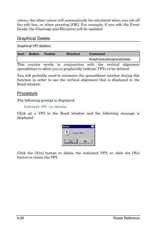
6-26 Roads Reference
values, the other values will automatically be calculated when you tab off the edit box, or when pressing [OK]. For example, if you edit the Front Grade, the Chainage and Elevation will be updated.
Graphical Delete
Graphical VPI deletion
Icon Button Toolbar Shortcut Command
RoadVerticalGraphicalDelete
This routine works in conjunction with the vertical alignment spreadsheet to allow you to graphically indicate VPI's to be deleted.
You will probably need to minimize the spreadsheet window during this function in order to see the vertical alignment that is displayed in the Road window.
Procedure
The following prompt is displayed:
Indicate VPI to delete
Click on a VPI in the Road window and the following message is displayed:
Click the [Yes] button to delete the indicated VPI, or click the [No] button to retain the VPI.

Alignment Menu 6-27
Graphical Edit
Graphical VPI editing
Icon Button Toolbar Shortcut Command
RoadVerticalGraphicalEdit
This routine works in conjunction with the vertical alignment spreadsheet to allow you to graphically indicate VPI's to be edited.
You will probably need to minimize the spreadsheet window during this function in order to see the vertical alignment that is displayed in the Road window.
Procedure
The following prompt is displayed:
Indicate VPI to edit
Click on a VPI in the Road window and the Vertical Curve Details dialog is displayed.
Fill in the relevant data and click the [OK] button to continue.

6-28 Roads Reference
Graphical Move
Graphical VPI moving
Icon Button Toolbar Shortcut Command
RoadVerticalGraphicalMove
This routine works in conjunction with the vertical alignment spreadsheet to allow you to graphically move existing VPI's.
You will probably need to minimize the spreadsheet window during this function in order to see the vertical alignment that is displayed in the Road window.
Procedure
The following prompt is displayed:
Indicate VPI to move
Click on an existing VPI in the Road window and the following prompt is displayed:
Indicate new position for VPI
Click on a position in the Road window and the VPI is updated to reflect the new position. The new VPI position is displayed on the screen as the mouse is moved. Right click during the second part of the procedure to cancel the move.

Alignment Menu 6-29
Ground Lines
Select ground lines to display
Icon Button Toolbar Shortcut Command
RoadVerticalGroundLines
This function allows you to select additional lines to be displayed along with the vertical alignment. Up to 4 extra lines from any road layer can be displayed. The line to be displayed is taken from offsets or PLC's and the colour of the line may be specified.
Procedure
The Ground Line Details dialog is displayed.
On - Line 1 to Line 4 Check this option to turn on the display of the selected line.
Layer - Line 1 to Line 4 Select the layer from which the longsection should be extracted.
PLC - Line 1 to Line 4 Check this option and enter the point location code (PLC) of the points that form the longsection. Points left of the centreline must be entered as a negative value.
Offset - Line 1 to Line 4 Enter the offset of the points that form the longsection. Only available if the PLC option is not checked. Offsets left of the centreline must be entered as a negative value.

6-30 Roads Reference
Height - Line 1 to Line 4 Enter a height constant for the selected ground line. e.g. Enter -1.5 to display a line 1.5 m below the selected ground line.
Pen Button - Line 1 to Line 4 Click this button to select the pen in which the selected line should be drawn.
User Defined Lines - Plot column
Enter Yes or No to specify whether this line should be plotted. Right click on the cell to toggle the current entry.
User Defined Lines - From Chainage column
Enter the start chainage of this line.
User Defined Lines - From Elevation column
Enter the start elevation of this line.
User Defined Lines - To Chainage column
Enter the end chainage of this line.
User Defined Lines - To Elevation column
Enter the end elevation of this line.
User Defined Lines - Pen column
Enter the pen number of the colour in which this line should be displayed. Right click the cell to display the colour selection dialog.
Show Gradelimits from Design Criteria
Check this option to show the grade limit envelope from the design criteria.
Fill in the relevant data and click the [OK] button to continue.
Alignment Menu 6-31
Review Alignment
List alignment details
Icon Button Toolbar Shortcut Command
RoadVerticalReviewAlignment
This routine produces a detailed listing of the vertical curve details.
Each VPI (vertical point of intersection) is listed along with its elevation, the k values, grades, high and low points as well as the beginning and ends of the vertical curves.
See Abridged Review for a more compact style of listing.
Make sure the Output Window is open to see the listing on the screen.
Procedure
The Output Manager dialog is displayed in order for you to set output options. Click the [OK] button to accept the settings.

6-32 Roads Reference
Abridged Review
List alignment details in shortened form
Icon Button Toolbar Shortcut Command
RoadVerticalAbridgedReview
This option is similar to Review Alignment. It also lists vertical alignment details to the screen, but does not list extra information such as low and high points. Use this facility for fast, preliminary listings.
Make sure the Output Window is open to see the listing on the screen.
Procedure
The Output Manager dialog is displayed in order for you to set output options. Click the [OK] button to accept the settings.
Generate Levels
Generate centreline levels
Icon Button Toolbar Shortcut Command
RoadVerticalGenerateLevels
This routine is used to generate elevations along the alignment for the chainages in the road file. A start chainage and stop chainage must be supplied. These chainages should obviously fall within the available range of the alignment.
The generated levels are stored in Layer 128 of the active roads database. In the case of Single Carriageway roads, they are stored on the centerline and, for Dual Carriageway roads, 0.5m left and right of the centreline. Layer 128 may be manipulated as a normal cross section for plotting purposes and will always be assumed to hold the current elevations for the designed chainage values.
Layer 128 may also be edited and used for data entry. This means that designs can be produced that follow no alignment whatsoever. This is useful in circumstances such as rehabilitation or wearing layer modifications, as well as shoulder widening, because survey data can be inserted into Layer 128 automatically and this becomes an "alignment" but no vertical adjustment to the existing layer takes place.

Alignment Menu 6-33
Procedure
The Chainage Range Details dialog is displayed.
Specify the start and stop chainages and click the [OK] button to continue.
The Output Manager dialog is displayed in order for you to set output options. Click the [OK] button to accept the settings.
6-34 Roads Reference
K Value
Calculate curve length by K value
Icon Button Toolbar Shortcut Command
RoadVerticalKValue
This option allows you to enter a specific K value for a certain VPI. The routine then calculates the curve length to achieve this K value and prints it to the screen or the printer depending on the option chosen.
This curve length, or a rounded equivalent thereof, can then be entered into the alignment (it is not done automatically).
Make sure that the Output Window is open in order to see the results of the calculation.
Procedure
The K Curve Details dialog is displayed.
Fill in the curve number and the required K value and click the [OK] button to continue.
The Output Manager dialog is displayed in order for you to set output options. Click the [OK] button to accept the settings.

Alignment Menu 6-35
Fit Curve
Fit a vertical curve through a fixed point
Icon Button Toolbar Shortcut Command
RoadVerticalFitCurve
This option allows you to choose a particular curve number and then set a chainage and an elevation for a point on that curve.
The routine then calculates the curve length and the K value that will result in a curve through that point and prints them to the screen or the printer depending on the option chosen.
Procedure
The Curve Fit Details dialog is displayed.
Curve number for fit Enter the number of the VPI for which a curve should be fitted.
Point to pass through - Chainage and Elevation
Enter the chainage and elevation of the point that the fitted curve must pass through.
Fill in the relevant details and click the [OK] button to continue. The Output Manager dialog is displayed in order for you to set output options. Click the [OK] button to accept the settings.

6-36 Roads Reference
Edge Levels
These functions generate the center portion of a road alignment (from left carriageway shoulder to right carriageway shoulder) and store it in a specified layer of the active road file. The super-elevation to apply to the road and the physical carriageway widths are controlled by the design data specified in a spreadsheet.
If design data has been changed but fresh section data was not yet regenerated, a warning message will remind you to generate section data.
Edit Super
Edit edge control data
Icon Button Toolbar Shortcut Command
RoadEdgeEditSuper
The edge level control data is stored in ASCII format in the design file of the active road. Entry is done via a spreadsheet.
The data in the spreadsheet controls the crossfalls, the left and right widths of the road, and the templates to be used. The spreadsheet has three pages. The first page is used to specify cross-falls, the second the carriageway widths (and is different for single- and dual carriageway roads), and the third the templates. When running Apply Template the templates specified in the first column of the templates page will be Applied, while the templates in the subsequent columns will be Added to the extremes of the existing section. The only compulsory entries into the templates page are the Chainage and first template column.
The start and end detail of all change of state points must be included. The routine will apply constant widths and crossfalls between two identical entries and work out a lineal progression of change between two successive entries that differ. Use Review Control to get a clearer understanding of your spreadsheet data.
Rounding can also be set in the Round column of the crossfall page. The figure that should be entered is the length of parabolic curve that will be applied to the elevations along the road edges where one grade changes to another. This provides smooth transitions in super elevation in to and out of curves.
If a template is to be applied later during the area calculation, then the number to be used should be entered in the Template page. Note that

Alignment Menu 6-37
the road width and crossfall details that are entered in the spreadsheet will override those that are contained in the template. The template number may be checked against its path and name by selecting Tools � Template Paths.
Two graphs will be drawn on the Roads window while in the Edit Edge Levels mode.
The first graph represents the super-elevation data. It's X-axis represents chainage values in meters while it's Y-axis represents super-elevation rates in percentage. A line drawn at zero super-elevation displays the horizontal alignment. Thick lines will indicate horizontal curves, while transition curves will be indicated as gaps in the line.
The second graph will be drawn above the super elevation graph and represents the road widths. It's X-axis represents chainage values in meters, while it's Y-axis represents widths in meters. Apart from the graphical editing functions documented below, there are also a number of shortcut keys that can be used to manipulate the view or to edit the alignment:
M Magnify around the cursor.
D De-magnify around the cursor.
R Redraw the alignment to its limits.
S Refresh the display.
H Jump to the nearest horizontal alignment point.
J Jump to the nearest superelevation or width break point.

6-38 Roads Reference
Graphical Insert
Graphical super elevation and width break point insertion
Icon Button Toolbar Shortcut Command
RoadEdgeGraphicalInsert
This routine works in conjunction with the Edge levels spreadsheet to allow you to graphically indicate super elevation and width break point positions.
You will probably need to minimize the spreadsheet window during this function in order to see the vertical alignment that is displayed in the Road window.
Procedure
The following prompt is displayed:
Indicate position for new super elevation / width change
Click on a position on the Super elevation graph in the Road window and the Super Details dialog is displayed.
Change the settings to suit and click on the [OK] button. Use the same function to insert a Width change point by clicking on a position on the Width graph in the Roads window. The Width details dialog will be displayed.
Fill in the carriageway widths and chainage and click the [OK] button to continue.

Alignment Menu 6-39
Graphical Delete
Graphical Super elevation and width break point deletion
Icon Button Toolbar Shortcut Command
RoadEdgeGraphicalDelete
This routine works in conjunction with the Edge levels spreadsheet to allow you to graphically indicate super elevation and width break point positions to be deleted.
You will probably need to minimize the spreadsheet window during this function in order to see the vertical alignment that is displayed in the Road window.
Procedure
The following prompt is displayed:
Indicate Super elevation / width point to delete
Click on a super elevation or width point in the Road window. A confirmation message will be displayed. Click the [Yes] button to delete the indicated super-elevation or width point or click the [No] button to retain the super-elevation or width point.

6-40 Roads Reference
Graphical Edit
Graphical Super elevation and width break point edition
Icon Button Toolbar Shortcut Command
RoadVerticalGraphicalEdit
This routine works in conjunction with the Edge levels spreadsheet to allow you to graphically indicate super elevation and width break point positions to be edited.
You will probably need to minimize the spreadsheet window during this function in order to see the vertical alignment that is displayed in the Road window.
Procedure
The following prompt is displayed:
Indicate Super elevation / width point to edit
Click on a super elevation or width break point in the Road window and the Edit dialog is displayed.
Use the same function to edit a Width change point by clicking on a position on the Width graph in the Roads window. The Width details dialog will be displayed.
If you are working with a single carriageway road the following dialog will be displayed:

Alignment Menu 6-41
However, if you are working on a dual carriageway road this dialog will be displayed:
The pivot points are indicated with a black circle. Specify the pivot positions, distance to the median and shoulder break point as indicated by the dimension lines. Also enter the chainage value.
Enter the carriageway width as indicated by the dimension lines, as well as the chainage. Click the [OK] button to continue.

6-42 Roads Reference
Graphical Move
Graphical Super elevation and width break point moving
Icon Button Toolbar Shortcut Command
RoadEdgeGraphicalMove
This routine works in conjunction with the Edge levels spreadsheet to allow you to graphically move super elevation and width break points.
You will probably need to minimize the spreadsheet window during this function in order to see the vertical alignment that is displayed in the Road window.
Procedure
The following prompt is displayed:
Indicate Super elevation / width point to move
Click on an existing super elevation or width break point in the Road window and the following prompt is displayed:
Indicate new position for Super elevation / width point
Click on a position in the Road window and the point is updated to reflect the new position. The new point position is displayed on the screen as the mouse is moved. Right click during the second part of the procedure to cancel the move.

Alignment Menu 6-43
Edge Level Lines
Specify the colour setup for the super-elevation and width graphs
Icon Button Toolbar Shortcut Command
This function allows you to specify the colours with which the super elevation and width graphs will be drawn. You can also specify the spacing between the super elevation and the width graphs using this function.
Procedure
The Edge Level lines dialog is displayed.
Shoulder BP Specify the pen in which the shoulder break point must be displayed on the width graph.
Center Line Specify the pen in which the center line must be displayed on the width graph.
Median BP Specify the pen in which the median break point must be displayed on the width graph.
Pivot Points Specify the pen in which the pivot point must be displayed on the width graph.
Left Edge Line Specify the pen in which the left edge must be displayed on the superelevation graph.
Right Edge Line Specify the pen in which the right edge must be displayed on the superelevation graph.
View Spacing Specify the spacing between the superelevation graph and the width graph.
Fill in the relevant data and click the [OK] button to continue.

6-44 Roads Reference
Slave Super
Slave edge control to horizontal alignment
Icon Button Toolbar Shortcut Command
RoadEdgeSlaveSuper
This option is the alternative to Edit Super. It allows the user to 'slave' the control data to the horizontal alignment information. This 'slaved' data is then accessible in the spreadsheet and may be subsequently modified by using Edit Super.
For each curve on the horizontal alignment, a dialog box will be displayed showing the Beginning (BCC) and End (ECC) Chainage for the curve. If you are using the Design Criteria, the following will automatically be calculated according to the design criteria and design rules as stipulated:
• Super elevation development length INTO the curve.
• % of development length that should take place before the BCC.
• Runoff length for the super elevation OUT of the curve.
• % of runoff length that should take place after the ECC.
• The maximum value (%) that the super elevation will attain in the curve.
Civil Designer can also handle Reverse Curves, Broken-Back curves and Compound curves. The program will automatically check for the above conditions and apply the appropriate design.
Once all the curves have been entered, the program converts the information into a spreadsheet layout. The data in the spreadsheet can be viewed or edited. Only the Super Elevation spreadsheet will be modified during Slave Super. It must be emphasized that the edge control data, once it is in spreadsheet form, is entirely independent of the horizontal curve data and does not interfere with the curve information in any way.

Alignment Menu 6-45
Procedure
The Slave Super Dialog will be displayed.
Press the [Recalculate All] button to recalculate the superelevation grades and development lengths for all the horizontal curves, or use the [Recalculate] button and the [Next]/[Previous] buttons to scroll through the curves and recalculate them one by one.
When pressing the [Recalculate]/[Recalculate All] buttons, the values on the dialog will be calculated automatically, provided that the [Use Design Criteria] checkbox was checked. Any of these values can however be modified. Click the [Close] button to continue. The calculated superelevation data will be entered into the spreadsheet.
If the entered data causes the super-elevation for a curve to overlap with that of the previous curve then the following message is displayed:

6-46 Roads Reference
Press [YES] to ignore the curve and continue. Press [NO] to cancel the routine, but retain the control data up to this point.
If the Horizontal curve is preceded by a transition curve and the super-elevation development length differs from the horizontal transition curve length, the following message will be displayed:
Press [No] not to re-generate the alignment with the calculated transition lengths. If you select [Yes], the program will automatically modify the relative transition lengths, re-coordinate the alignment, extract new cross sections and re-generate the vertical alignment.
If the tangent length between reverse curves is less than the development length needed, the following warning message will be displayed:
Press [OK] to continue.

Alignment Menu 6-47
Review Control
List edge control details
Icon Button Toolbar Shortcut Command
RoadEdgeReviewControl
This routine produces a listing of the edge control data. Each stretch between control chainages is labeled as to whether the super elevation is constant or varying over that stretch.
It is simply a composite and annotated copy of the spreadsheet pages.
Make sure that the Output Window is open to see the results.
Procedure
The Output Manager dialog is displayed in order for you to set output options. Click the [OK] button to accept the settings.

6-48 Roads Reference
Generate Levels
Generate edge levels from the edge control details
Icon Button Toolbar Shortcut Command
RoadEdgeGenerateLevels
This routine generates mini sections in the form of edge levels for those chainages that are already in the road file, and that have vertical alignment elevations.
Because these sections are created from the vertical curve, it is necessary to use Alignment ► Vertical ► Generate Levels, or insert road levels into Layer 128 manually, before using this procedure.
The edge levels are created by applying the control data to the selected template. The start and end chainage for the calculation must be entered as well as the layer in the road database in which the sections should be stored. A depth below the vertical alignment may also be specified so that the entire section is generated at that depth below the design line. This enables earthwork conditions and layerworks to be calculated from the same final design grade line.
The routine generates the cross sections for the road between the left and right outer carriageway edges.
For a single carriageway template the section created contains three points, one point on the road centerline (CL) and a point on either side of the center at each road edge. The offsets of the edges are specified by the carriageway widths in the spreadsheet.
For dual carriageway templates, four or more points are produced. These are the Shoulder Break Point (SBP) and Median Break Point (MBP) for both carriageways and the median details that are inserted between the carriageways. The offsets of the edges are specified by the carriageway widths in the spreadsheet.
In the case of dual carriageways, no attempt is made to transition the road state between one template and another if they have differing widths. Use Section ► Expand/Shrink for this purpose. You can however vary widths within a single template by specifying the various changes in the Edge Control spreadsheet.

Alignment Menu 6-49
Procedure
The Range Details dialog is displayed.
Start chainage Enter the first chainage of the range of chainages for which edge level sections should be calculated.
Stop chainage Enter the last chainage of the range of chainages for which edge level sections should be calculated.
Depth below vertical alignment
Enter the depth below the design line (the current vertical alignment) at which the sections should be generated.
Layer for edge levels Select the layer in which the generated sections should be stored.
Fill in the relevant data and click the [OK] button to continue.
The Output Manager dialog is displayed in order for you to set output options. Click the [OK] button to accept the settings.
Rehabilitation
Extract roads data from a DTM surface.
Icon Button Toolbar Shortcut Command
RoadRehab
This function will extract Horizontal alignment, Vertical alignment and super elevation data from a DTM surface. These alignments can then be altered using the normal roads functions after which a template can be applied.
Procedure
The Road Rehabilitation dialog will be displayed.
Specify whether the road has to be extracted as a single or dual carriageway road using the “Type of Road” radio buttons.

6-50 Roads Reference
Single Carriageway
Type of Road Select wether the road must be extracted as a Single or dual carriageway road
Alignment Elements to extract.
Select which elements to extract from the DTM model, Horizontal, Vertical or Super elevation.
(Extract elements at offset from CL) Vertical alignement
If the Vertical Alignment checkbox is checked, specify the offset from the centerline where the vertical alignment must be extracted from the DTM.
(Extract elements at offset from CL) Left / Right Super
If the Super Elevation checkbox is checked, specify the two offsets from the centreline between which the crossfall at each cross section must be calculated.
(Accuracy Settings) Vertical Rounding (R)
Enter the rounding factor for vertical curve lengths. The calculated curve lengths which will be entered into the vertical alignment spreadsheet by the extraction routine will be rounded to the nearest (R).
(Accuracy Settings) Vertical Toerance
Enter the maximum allowable hight difference between the ground model and the vertical alignment to be calculated by the program.
(Accuracy Settings) Super Rounding (R)
Enter the rounding factor for super elevation grades. The calculated grades which will be entered into the edge levels spreadsheet by the extraction routine will be rounded to the nearest (R)
(Accuracy Settings) Super Toerance
Enter the maximum allowable difference in grade between the ground model and the super elevation grades to be calculated by the program.

Alignment Menu 6-51
Dual Carriageway
Type of Road Select wether the road must be extracted as a Single or dual carriageway road
Alignment Elements to extract.
Select which elements to extract from the DTM model, Horizontal, Vertical or Super elevation.
(Extract elements at offset from CL) Left / Right Vertical alignement
If the Vertical Alignment checkbox is checked, specify the offsets from the centerline where the vertical alignments must be extracted from the DTM.
(Extract elements at offset from CL) Left / Right Super
If the Super Elevation checkbox is checked, specify the two offsets from the centreline between which the crossfall at each cross section must be calculated.
(Accuracy Settings) Vertical Rounding (R)
Enter the rounding factor for vertical curve lengths. The calculated curve lengths which will be entered into the vertical alignment spreadsheet by the extraction routine will be rounded to the nearest (R).
(Accuracy Settings) Vertical Toerance
Enter the maximum allowable hight difference between the ground model and the vertical alignment to be calculated by the program.
(Accuracy Settings) Super Rounding (R)
Enter the rounding factor for super elevation grades. The calculated grades which will be entered into the edge levels spreadsheet by the extraction routine will be rounded to the nearest (R).
(Accuracy Settings) Super Toerance
Enter the maximum allowable difference in grade between the ground model and the super elevation grades to be calculated by the program.
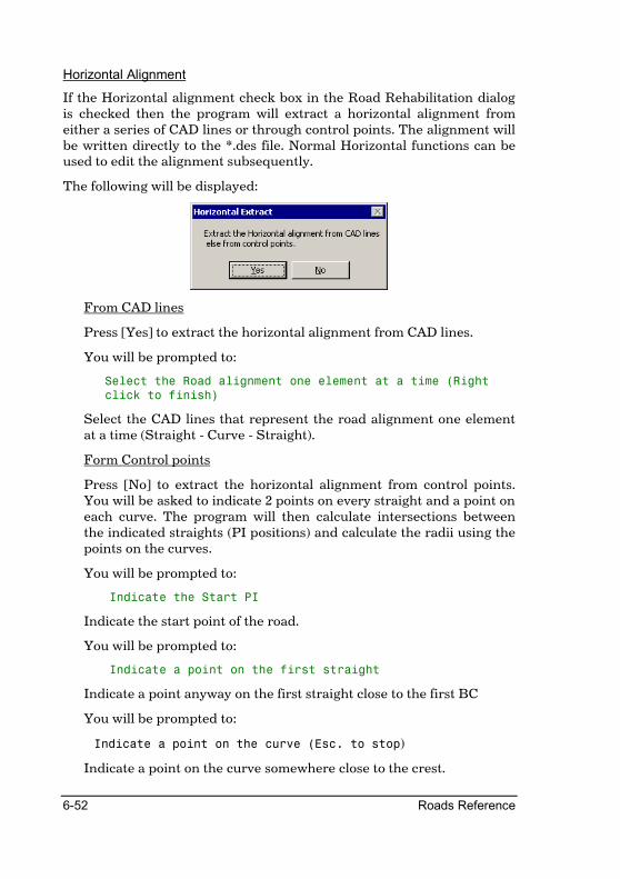
6-52 Roads Reference
Horizontal Alignment
If the Horizontal alignment check box in the Road Rehabilitation dialog is checked then the program will extract a horizontal alignment from either a series of CAD lines or through control points. The alignment will be written directly to the *.des file. Normal Horizontal functions can be used to edit the alignment subsequently.
The following will be displayed:
From CAD lines
Press [Yes] to extract the horizontal alignment from CAD lines.
You will be prompted to:
Select the Road alignment one element at a time (Right
click to finish)
Select the CAD lines that represent the road alignment one element at a time (Straight - Curve - Straight).
Form Control points
Press [No] to extract the horizontal alignment from control points. You will be asked to indicate 2 points on every straight and a point on each curve. The program will then calculate intersections between the indicated straights (PI positions) and calculate the radii using the points on the curves.
You will be prompted to:
Indicate the Start PI
Indicate the start point of the road.
You will be prompted to:
Indicate a point on the first straight
Indicate a point anyway on the first straight close to the first BC
You will be prompted to:
Indicate a point on the curve (Esc. to stop)
Indicate a point on the curve somewhere close to the crest.

Alignment Menu 6-53
You will be prompted to:
Indicate First Point on the next straight (Esc. to stop)
Indicate a point on the next straight.
Indicate Next point on the straight (Esc. to stop)
Indicate another point on the straight. The process will be repeated until you press [Esc].
Vertical Alignment
If the Vertical alignment check box in the Road Rehabilitation dialog is checked then the program will extract the vertical alignment/s from the ground model. The calculated vertical alignment/s will be entered directly into the *.des file.
The Coordination details dialog will be displayed to calculate centreline coordinates at regular chainage intervals.
The Cross Section Extraction dialog will be displayed to extract ground cross sections.
The program will enter into a iteration process to fit a vertical alignment onto the extracted ground cross sections using the Vertical accuracy settings as an indication of when to stop the process. The smaller the accuracy setting the closer the alignment will follow the ground, but the longer the process will take. A small accuracy setting will also cause more small vertical curves.
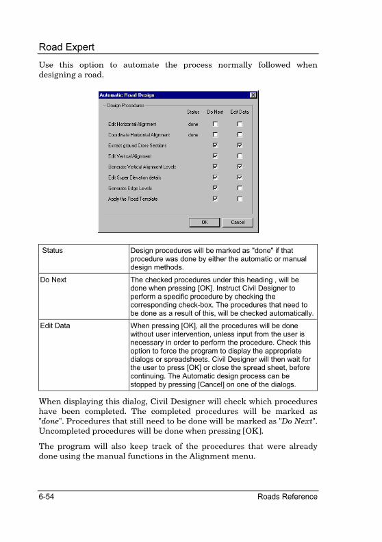
6-54 Roads Reference
Road Expert
Use this option to automate the process normally followed when designing a road.
Status Design procedures will be marked as "done" if that procedure was done by either the automatic or manual design methods.
Do Next The checked procedures under this heading , will be done when pressing [OK]. Instruct Civil Designer to perform a specific procedure by checking the corresponding check-box. The procedures that need to be done as a result of this, will be checked automatically.
Edit Data When pressing [OK], all the procedures will be done without user intervention, unless input from the user is necessary in order to perform the procedure. Check this option to force the program to display the appropriate dialogs or spreadsheets. Civil Designer will then wait for the user to press [OK] or close the spread sheet, before continuing. The Automatic design process can be stopped by pressing [Cancel] on one of the dialogs.
When displaying this dialog, Civil Designer will check which procedures have been completed. The completed procedures will be marked as "done". Procedures that still need to be done will be marked as "Do Next". Uncompleted procedures will be done when pressing [OK].
The program will also keep track of the procedures that were already done using the manual functions in the Alignment menu.

Alignment Menu 6-55
Design Criteria
Specify road design criteria
Icon Button Toolbar Shortcut Command
RoadVerticalDesignCriteria
This function allows you to specify design criteria for Horizontal and Vertical alignment as well as Super Elevation design. You can either use the default TRH 17 values, or create and use your own design criteria file.
Designing roads that do not meet the design criteria specification does not stop you from using them as such. The design criteria serve only as a warning to the user.
Check the Use Design Criteria check box to use the design criteria in the design process. Specify the Design speed to for the road to be designed using the Design Speed combo box.
Press the [Save As] button to save the current design criteria to an ASCII file. Similarly use the [Load] button to load a Design Criteria file.

6-56 Roads Reference
General Settings
The general settings allow you to switch the Design Criteria option on or off.
Use Design Criteria Check this to use design criteria during the road design process.
Design Speed Select the design to be used for the current project.
Load Button Press this button to load a *.vdc, design criteria file.
Save As Button Press this button to save the dialog contents to a *.vdc, design criteria file.
Restore Defaults Press this button to restore the contents of the spreadsheets to the default TRH 17 values.
Grade Pen Click this button to select the pen colour in which grade envelopes should be drawn.
Terrain Type Select the type of terrain through which the vertical alignment is being applied.
TRH development Check this button to apply the TRH 17 development method.
Superelevation Graph Press This button to display the Superelevation rates graph
Super at Straights Enter the super elevation rate for straights.
Lane Factor Enter the lane factor to ensure antiquate adjustment when calculating run-off lengths. (l)

Alignment Menu 6-57
Horizontal Alignment Design Criteria
Enter the Horizontal Design Criteria into the [Horizontal] spreadsheet.
Min Radius Enter the minimum curve radius per design speed.
Min Curve Len Enter the minimum radial curve length per design speed.
Max Curve Len Enter the maximum radial curve length
Small Deflection Limit For deflection angles less than this value, the minimum length of the curve specified in the [Min Curve Len] column, will be increased by [Increment] for each 1 degree decrease in the deflection angle.
Increment Enter the increment by which the minimum curve length will be increased, for each degree less than the [Small Deflection Limit].
Compound Crv Max R1/R2 Enter the maximum radius-ratio for compound curves. Flatter curve radius divided by the sharper curve radius.
Min Tangent Length Enter the minimum tangent length for broken-back curves. Two successive curves will not be recognized as broken-back curves if the tangent is greater than 500 m.
Each row in the spreadsheet represents a design speed as indicated by the row headings. When any of these values are exceeded during the Horizontal alignment design, warnings will be displayed on the Design Center window and when running the Review Alignment function.

6-58 Roads Reference
Vertical Alignment Design Criteria
Enter the Vertical Alignment design criteria into the [Vertical] spreadsheet.
Each row in the spreadsheet represents a design speed as indicated by the row headings.
Min K Crest column Enter the minimum K value for crest vertical curves at this design speed.
Min K Sag column Enter the minimum K value for sag vertical curves at this design speed.
Min Len column Enter the minimum length of any vertical curve at this design speed.
Max Grade Flat column Enter the maximum grade between VPI's in flat terrain at this design speed.
Max Grade Rolling column Enter the maximum grade between VPI's in rolling terrain at this design speed.
Max Grade Mountainous column
Enter the maximum grade between VPI's in mountainous terrain at this design speed.
When designing the Vertical alignment, the Road Window will display the grade criteria as a set of grade envelopes at each VPI. Furthermore, when using Review Alignment or Abridged Review, curves that do not pass the selected design criteria will be noted as to the reasons for that failure. Inserting a VPI will automatically calculate a curve length based on the specified K value for the type of curve.

Alignment Menu 6-59
Super-elevation Design Criteria
Enter the Super-elevation design criteria into the [Super] spreadsheet.
Each row in the spreadsheet represents a design speed as indicated by the row headings.
Slope Factor Enter the The relative slope factor for the relative design speed (s).
Min Runoff Enter the Length of superelevation run-off per design speed (L)
Max Super Enter the maximum Superelevation value. This is the largest superelevation value that will be used.
Compound curve L If the length of the first circular curve (CT) of a compound curve pair is less than this value, Case 1 will be applied, otherwise Case 2 will be applied. These cases are explained in the design process.

6-60 Roads Reference
Super-Elevation
The Super elevation design criteria will be applied when using the Slave Super function. All the data on the dialogs will automatically be calculated using the design criteria. The calculated values can be overwritten at any time while running Slave Super.
Superelevation design process
Civil Designer will automatically evaluate each horizontal curve pair and assistant whether they are single curves, reverse curves, broken-back curves, or compound curves. It will then apply the design criteria and design rules stipulated here according to the specific nature of each curve.
The super elevation rate (e) is the full rate of super elevation for a specific curve and will be read from the Super-elevation rate curve.
The run-off length (L) is calculated as the difference in height between the fully super-elevated carriageway edge and the axis of rotation divided by the relative slope between them. This value will be calculated by the following formula, but will always be greater than the minimum run-off length as specified in the [Super] spreadsheet of the Design Criteria dialog.
L = (w*e*s*l) / 100
where:
L Length of super-elevation run-off (m)
w Lane width (m). This value will be read from the Edge level spreadsheet at the width break point closest to the horizontal curve. If no edge levels are available, it will be read from the first road template specified.
e Super-elevation. This value will be linearly interpolated from the Super-elevation graph.
l Lane Factor. You can specify this value on the Design Criteria dialog.
s The relative slope factor. This value will be read from the Slope Factor column on the [Super] spreadsheet of the Design Criteria dialog.
Lc = (w*e*s*l) / 100
where

Alignment Menu 6-61
e is the super-elevation rate on the straights. This value can be specified in the Design Criteria dialog.
TRH 17 Lane Factors for Super-elevation run-off
CROSS SECTION NR. OF LANES LANE FACTOR MEDIAN WIDTH
Undivided 2 1.0 -
Undivided 3 1.2 -
Undivided 4 1.5 -
Undivided 2 1.5 Less than 4.6m
Undivided 3 2.0 Less than 4.6m
Divided 2 1.0 or 1.5 4.6 to 12.2m
Divided 3 1.2 or 2.0 4.6 to 12.2m
Divided 2 1.0 Greater than 12.2m
Divided 3 1.2 Greater than 12.2m
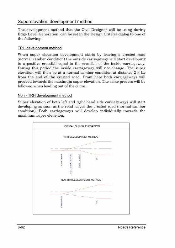
6-62 Roads Reference
Superelevation development method
The development method that the Civil Designer will be using during Edge Level Generation, can be set in the Design Criteria dialog to one of the following:
TRH development method
When super elevation development starts by leaving a crested road (normal camber condition) the outside carriageway will start developing to a positive crossfall equal to the crossfall of the inside carriageway. During this period the inside carriageway will not change. The super elevation will then be at a normal camber condition at distance 2 x Lc from the end of the crested road. From here both carriageways will proceed towards the maximum super elevation. The same process will be followed when leading out of the curve.
Non - TRH development method
Super elevation of both left and right hand side carriageways will start developing as soon as the road leaves the crested road (normal camber condition). Both carriageways will develop individually towards the maximum super elevation.
NOT TRH DEVELOPMENT METHOD
TRH DEVELOPMENT METHOD
NORMAL SUPER ELEVATION
NO
RM
AL C
AM
BE
R
FU
LL
NO
RM
AL C
AM
BE
R
LE
VE
L +
NO
RM
AL C
RO
SS
FA
LL
NO
RM
AL C
RO
SS
FA
LL
FU
LL

Alignment Menu 6-63
Super-elevation rates graph
Enter the radii at each design speed next to the appropriate super elevation rate (e) in percentage. When changing any of the values, the graph will be updated instantaneously. Press [OK] to accept and save the changes.

6-64 Roads Reference
Single Curve Super-elevation
Where a circular curve is preceded by a transition curve, the full super-elevation (e) will be achieved at the start of the circular curve. The length of the preceding transition length should be at least L - Lc.
When no transition curve precedes a circular curve, two- thirds of the full super-elevation (e) will be achieved on the preceding tangent and the remaining one -third in the circular curve.
BT
C
Lc Lc
L
e
e
1/3 L
e for straights
BT
C
BT
C
Lc Lc
L
e
e
e for straights
WITHOUT TRANSITION
WITH TRANSITION
NORMAL SUPER ELEVATION

Alignment Menu 6-65
Reverse Curves
A reversal of horizontal alignment should include a length of connecting tangents, or a section of equal length including spiral curves. The distance between circular curves is dictated by the requirements of super-elevation development.
CircularCurve
TransitionCurve
TransitionCurveTangent
2% 2%
CircularCurve
WITH TRANSITION
WITHOUT TRANSITION
REVERSE CURVES
L1L1
1/3L 2/3L 2/3L 1/3L
Tangent
BC
C
EC
C
BT
C1
ET
C1
BT
C2
BC
C2

6-66 Roads Reference
Broken-back Curves
The tangent length between two successive curves that form a broken-back curve should not be less than the [Min Tangent Length] value specified in the [Horizontal] spreadsheet. The rules that apply to broken-back curves will not be applied if the tangent length is greater than 500 m. The connecting tangent will have a single cross-fall as displayed in the figure below.
BROKEN BACK CURVES
WITHOUT TRANSITION
WITH TRANSITION
BC
C2
EC
C1
L1 L2
1/3L 2/3L 2/3L 1/3L
Tangent
2% 2%
BT
C1
ET
C1
BT
C2
BC
C2
CircularCurve
TransitionCurve Tangent
TransitionCurve
CircularCurve

Alignment Menu 6-67
Compound Curves
M is the minimum run-off length as specified in the [Super] spreadsheet of Design criteria dialog. The development length between the two curves will always be at least M. Civil Designer will apply either Case 1 or Case 2, depending on the length of the first circular curve. If this length is less than CT, it will apply Case 1 otherwise it will apply Case 2. CT is the value specified in the [Compound Curve L] column of the [Super] spreadsheet in the Design Criteria dialog.
BC
C
PC
C
Lc Lc
L
eL
eL
1/3 L
e for straights
eS
eS
Greater than CT
M. min.
Lc Lc
2/3 L
2/3 eL
2/3 eLe for straights
BC
C
eS
eS
PC
C
CT or Less
CASE 1
CASE 2
COMPOUND CURVES

6-68 Roads Reference
Check Sight Distance
Do sight distance check.
Icon Button Toolbar Shortcut Command
RoadVerticalCheckSightDist
This function will calculate the areas along the road alignment where the driver cannot see the specified object over a specified minimum sight distance. These areas will be marked in the specified pen colour on either the Vertical, or Horizontal alignment.
The road design process must be completed for this routine to work properly, i.e. a final design road layer must exist. The program will do sight distance checking in both horizontal and vertical planes automatically.
The program will use the batter cross sections for sight checking. If the offset of the toe points are less than the specified road reserve, then the program will include ground points beyond the toe point and up to the road reserve width when doing sight distance checking.
The distance from the driver to the object will always be measured along the horizontal alignment while the sight line from the driver to the object (blue line) will be taken as a straight line. If this line crosses the toe point or the road reserve, whichever has the greater offset from the centre line, the program will register a horizontal failure.

Alignment Menu 6-69
Vertical sight failure will occur if a driver is unable to see the object over the minimum sight distance because of a vertical curve, or when cut banks restrict his vision as illustrated by the figure below.
Procedure
You must be in either Vertical Alignment or Horizontal Alignment edit mode. The Sight Distance Check dialog will be displayed:

6-70 Roads Reference
Fill in the relative information.
Press [OK]
The no sight envelopes will be drawn in either the Design centre window, or the Vertical Alignment window in the selected pen colour. If you run the function from the Vertical alignment window then horizontal failure will be indicated by a dotted line. If you run the function from the Horizontal alignment window then vertical failure will be indicated by a dotted line. The envelopes will also be printed in the output window.
Area/Volume Menu 7-1
Area/Volume Menu
These functions allow you to apply the template to the alignment and calculate or manipulate the road batters.
All the relevant routines take any two specified layers, connect the one to the other in a variety of possible ways, calculate the cut and fill areas between them and then generate earthwork volumes.
There are several optional ways of doing it:
• the edge batters can be set by slope or length.
• a template can be applied or added to a basic road carriageway.
• an optimized cut / fill position can be obtained.
• areas can be calculated through dumps or dams.
• special box cuts and bin quantities can be obtained.
Long runs through a variety of the above circumstances are possible
Input
In the case of a road calculation, you will usually use Apply Template after creating edge levels in Generate Levels under Alignment ► Edge
Levels and one or more templates in Tools ► Template Editor. In the case of terraces, you will probably have come from the section extraction routine in Terrain ► Cross Section ► Extract.
In every case you will at least provide:
• a start and end chainage for the stretch to calculate.
• a base layer which is typically the ground.
• a prick layer which is typically the design.

7-2 Roads Reference
Output
Printouts of the area routines gives the prick point locations, bank slopes, areas, stripped width and bank lengths.
The data generated is accumulated in the index and usually the next step would be running the volume routines to get quantities or the plotting routines to check your results.
It can happen that the first layer is not wide enough to provide a connection at the slope specified. If this occurs, the last data point will be extrapolated on a level plane for 50 meters. This will be attempted twice after which the section is aborted and no area calculated.
For each run, you specify two layer numbers. One is for the "base" which is typically the ground, and one is for the "batter" which is typically the design.
During the calculation, the second layer will have the prick points added to it. In other words, it will have two more points (one at each extremity) after the routine has been run.
Generally a road, and sometimes a terrace, will be built up of a number of stretches that are treated differently. For example, chainage 0 - 2480 may be template 1, 2500 - 3220 is template 2, 3240 -3440 has a special retaining wall, 3460 - 6420 is template 1 again, and so on.
Use Apply Template the first time to run each stretch individually. This does not have to be progressive. It is often a good idea to first run the whole job with the most common condition and then rerun the exceptions individually. Once any piece has been run once, the Use Index option can be used to recalculate the whole job (or any part of it) with whatever condition was originally set.
Notes
1. Users should be aware of two factors that can affect results from this program:
Minor inconsistencies may be noted in the arithmetic of the printed data. This is because the computer is working to its full precision but there is only space to print volumes to the nearest whole cubic meter.
One should also note that in cases where the topsoil volume is large relative to the overall quantities, what was a cut section could become a fill section. The illustration below is a normal section with cut and fill modified by the removal of a topsoil layer:
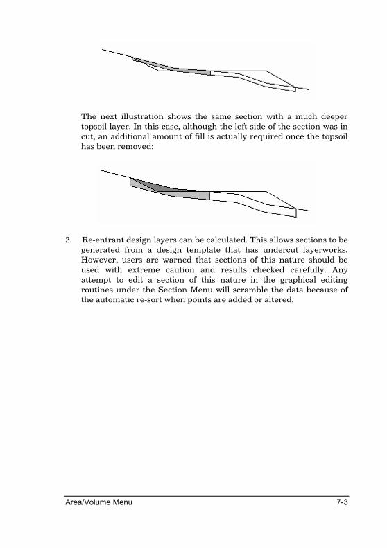
Area/Volume Menu 7-3
The next illustration shows the same section with a much deeper topsoil layer. In this case, although the left side of the section was in cut, an additional amount of fill is actually required once the topsoil has been removed:
2. Re-entrant design layers can be calculated. This allows sections to be generated from a design template that has undercut layerworks. However, users are warned that sections of this nature should be used with extreme caution and results checked carefully. Any attempt to edit a section of this nature in the graphical editing routines under the Section Menu will scramble the data because of the automatic re-sort when points are added or altered.

7-4 Roads Reference
Apply Template
Apply a template to the road shoulders
Icon Button Toolbar Shortcut Command
RoadAreaVolApplyTemplate
This routine is used to apply road cross section details beyond the limits of the carriageways by means of a template. The template would have been created in Template Editor under the Tools menu. Templates will automatically be applied at the specified skew angle for skew sections.
The routine presupposes that the design layer contains information up to the outer edge of the left and right carriageways, in other words the entire centre section of the road. Therefore, before this routine is run, you have to generate edge levels.
In the case of a rerun, the existing section data is first searched for the centre portion of the road (between the outer limits of the carriageways). This centre portion is retained and the outer parts are destroyed before new details from the specified template are applied. For this reason, if there are skew sections in the road, you must generate edge levels before re-applying the template.
The template name must be preset. The template name is specified when Generate Edge Levels is used. To check the template name against its file name, or to specify the template name and path, use the Template Paths facility under Tools.
The template specified in the first column of the Edge Level spreadsheet will be added to the shoulder points. The templates specified in the rest of the columns will be added to the toe points in chronological order.
After the run, the outer batter slopes will be stored in the index and the Area Indicator will be set to '1'.
To cater for specialist volume calculations, you may choose to direct the output to a spreadsheet. There will be a prompt for a file name and the data will be stored in this file in ASCII format.

Area/Volume Menu 7-5
Procedure
The Chainage Range dialog is displayed.
Start chainage Enter the first chainage of the range of chainages over which this function should be applied.
Stop chainage Enter the last chainage of the range of chainages over which this function should be applied.
Base layer Select the layer that forms the ground or base surface.
Batter layer Select the layer where the template section must be stored.
Spreadsheet output Check this option to have the results of the function saved in comma-delimited format suitable for loading into spreadsheets.
Fill in the relevant data and click the [OK] button to continue.
The Output Manager dialog is displayed in order for you to set output options. Click the [OK] button to accept the settings.
If you selected the Spreadsheet output option, then Windows’ standard save dialog is displayed in order for you to select a file to which to write. The drive and path automatically default to the last used drive and directory for this type of file.

7-6 Roads Reference
Set Batters
Calculate batters on road shoulders
Icon Button Toolbar Shortcut Command
RoadAreaVolSetBatters
This routine is used to create or recreate the outer batters (left and right) on the design layer. It is mainly used for terraces, simple roads, and those portions of a road that have been generated or manipulated manually after a template addition.
The slopes are expressed as 1:nn - so a value of '0' will result in a vertical slope and a value of '999' will result in a flat one. The batters may be forced to a minimum width left and right, in cut and fill. This will be an absolute figure relative to the centre line (e.g. "23'' will give prick points at 23m for that item unless the earthworks naturally extend beyond this) or a set distance from the shoulder break point. An entry of 0 allows the banks to behave normally.
The batter slope stored in the road file can be the specified slope or the adjusted slope after minimum bank lengths have been applied.
The Area Indicator stored in the index after running this routine will be '2' (See Road INDEX - Technical).
Procedure
The Chainage Range dialog is displayed.
Start chainage Enter the first chainage of the range of chainages over which this function should be applied.
Stop chainage Enter the last chainage of the range of chainages over which this function should be applied.
Base layer Select the layer that forms the ground or base surface.

Area/Volume Menu 7-7
Batter layer Select the layer where the template section must be stored.
Spreadsheet output Check this option to have the results of the function saved in comma-delimited format suitable for loading into spreadsheets.
Fill in the relevant data and click the [OK] button to continue.
The Batter Details dialog is displayed.
Minimum bank lengths Enter the minimum distance at which banks should end for the various conditions. Should the earthworks end before this distance has been reached then the batter slope will be adjusted to reach this offset. This offset can be relative to the centreline or the shoulders as selected further on in the dialog. An entry of 0 will ignore the minimum bank length check.
Batters to set Enter the batter slope (as 1 in ?) that the batter should be set to for the various conditions.
Set minimum bank lengths relative to
Select whether the minimum bank length should be checked relative to the offset from centreline or from the shoulder.
Store adjusted batters in index Check this box to have the batters as adjusted in order to reach the minimum bank lengths stored. If not checked, then the batter slopes as entered will be stored.
Fill in the relevant data and click the [OK] button to continue.
The Output Manager dialog is displayed in order for you to set output options. Click the [OK] button to accept the settings.
If you selected the Spreadsheet output option, then Windows’ standard save dialog is displayed in order for you to select a file to which to write. The drive and path automatically default to the last used drive and directory for this type of file.

7-8 Roads Reference
Dump Area
Dump area calculation
Icon Button Toolbar Shortcut Command
RoadAreaVolDumpArea
This routine is a special circumstance that permits the direct calculation of areas from a single layer but which creates another theoretical layer as a straight line between the extremities of the first one.
The created layer will be stored in the layer specified as the base (overwriting any data that is already there).
The calculation will only be valid if the line joining the two extremities is straight i.e. an even plane for the dump base.
Procedure
The Chainage Range dialog is displayed.
Start chainage Enter the first chainage of the range of chainages over which this function should be applied.
Stop chainage Enter the last chainage of the range of chainages over which this function should be applied.
Base layer Select the layer that forms the ground or base surface.
Batter layer Select the layer where the template section must be stored.
Spreadsheet output Check this option to have the results of the function saved in comma-delimited format suitable for loading into spreadsheets.
Fill in the relevant data and click the [OK] button to continue.
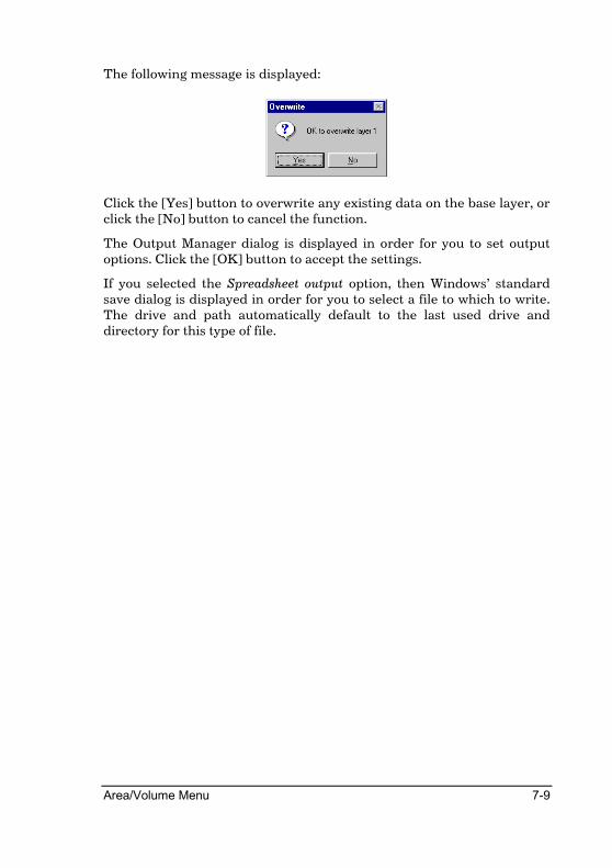
Area/Volume Menu 7-9
The following message is displayed:
Click the [Yes] button to overwrite any existing data on the base layer, or click the [No] button to cancel the function.
The Output Manager dialog is displayed in order for you to set output options. Click the [OK] button to accept the settings.
If you selected the Spreadsheet output option, then Windows’ standard save dialog is displayed in order for you to select a file to which to write. The drive and path automatically default to the last used drive and directory for this type of file.

7-10 Roads Reference
Dam Areas
Dam area calculation
Icon Button Toolbar Shortcut Command
RoadAreaVolDamArea
This routine enables the calculation of cross sectional areas of water in a dam. It requires that the ground or base cross section of the dam be stored in a suitable layer. Only a water level for the dam need be supplied.
A theoretical water surface is then created and stored in the layer specified as the batter (overwriting any data that is already there). Islands are catered for and included in the final layer. The wetted perimeter length is also printed.
An outline plan of the water surface is obtainable by translating the cross sections back into DTM points. This is done using Terrain ► Cross
Sections ► Translate.
Procedure
The Chainage Range dialog is displayed.
Start chainage Enter the first chainage of the range of chainages over which this function should be applied.
Stop chainage Enter the last chainage of the range of chainages over which this function should be applied.
Base layer Select the layer that forms the ground or base surface.
Batter layer Select the layer where the template section must be stored.
Spreadsheet output Check this option to have the results of the function saved in comma-delimited format suitable for loading into spreadsheets.
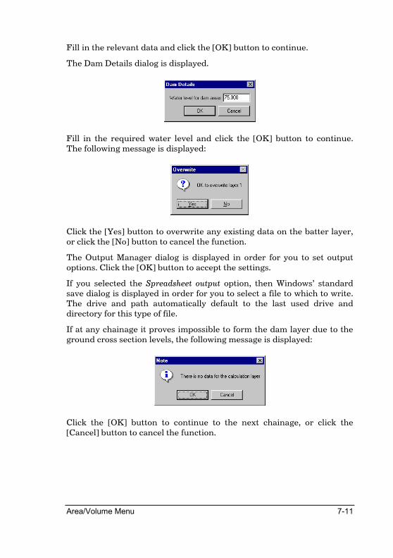
Area/Volume Menu 7-11
Fill in the relevant data and click the [OK] button to continue.
The Dam Details dialog is displayed.
Fill in the required water level and click the [OK] button to continue. The following message is displayed:
Click the [Yes] button to overwrite any existing data on the batter layer, or click the [No] button to cancel the function.
The Output Manager dialog is displayed in order for you to set output options. Click the [OK] button to accept the settings.
If you selected the Spreadsheet output option, then Windows’ standard save dialog is displayed in order for you to select a file to which to write. The drive and path automatically default to the last used drive and directory for this type of file.
If at any chainage it proves impossible to form the dam layer due to the ground cross section levels, the following message is displayed:
Click the [OK] button to continue to the next chainage, or click the [Cancel] button to cancel the function.
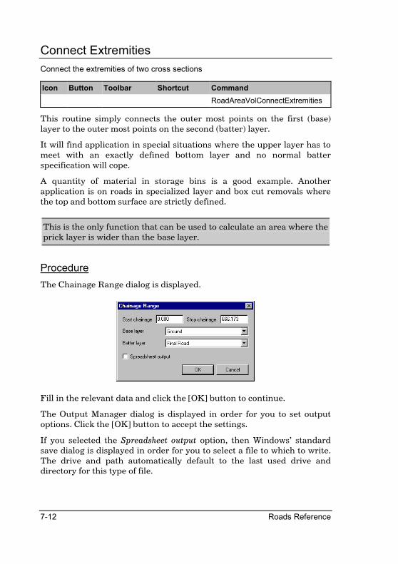
7-12 Roads Reference
Connect Extremities
Connect the extremities of two cross sections
Icon Button Toolbar Shortcut Command
RoadAreaVolConnectExtremities
This routine simply connects the outer most points on the first (base) layer to the outer most points on the second (batter) layer.
It will find application in special situations where the upper layer has to meet with an exactly defined bottom layer and no normal batter specification will cope.
A quantity of material in storage bins is a good example. Another application is on roads in specialized layer and box cut removals where the top and bottom surface are strictly defined.
This is the only function that can be used to calculate an area where the prick layer is wider than the base layer.
Procedure
The Chainage Range dialog is displayed.
Fill in the relevant data and click the [OK] button to continue.
The Output Manager dialog is displayed in order for you to set output options. Click the [OK] button to accept the settings.
If you selected the Spreadsheet output option, then Windows’ standard save dialog is displayed in order for you to select a file to which to write. The drive and path automatically default to the last used drive and directory for this type of file.

Area/Volume Menu 7-13
Add Template
Add template details to the extremities of an existing cross section
Icon Button Toolbar Shortcut Command
RoadAreaVolAddTemplate
This routine is used to add the compulsory and cut/fill conditions of a pre-defined template to the extremities of the batter layer. Typical uses include the addition of drains at the toe of batter slopes, the addition of catchwater berms to existing cuts and any section that is very complicated or where multiple intersections of the ground are required.
The number of the template to apply must be provided. To check the number of a template against its name and path, use Tools ► Template
Paths.
The distinguishing feature of this routine (as opposed to Apply Template) is that the entire profile of the existing section is left unchanged. In Apply Template, only the center portion comprising the carriageways is left unchanged.
Procedure
The Add Template Details dialog is displayed.
Specify the template number to add on and click the [OK] button to continue.

7-14 Roads Reference
The Chainage Range dialog is displayed.
Start chainage Enter the first chainage of the range of chainages over which this function should be applied.
Stop chainage Enter the last chainage of the range of chainages over which this function should be applied.
Base layer Select the layer that forms the ground or base surface.
Batter layer Select the layer where the template section must be stored.
Spreadsheet output Check this option to have the results of the function saved in comma-delimited format suitable for loading into spreadsheets.
Fill in the relevant data and click the [OK] button to continue.
The Output Manager dialog is displayed in order for you to set output options. Click the [OK] button to accept the settings.
If you selected the Spreadsheet output option, then Windows’ standard save dialog is displayed in order for you to select a file to which to write. The drive and path automatically default to the last used drive and directory for this type of file.

Area/Volume Menu 7-15
Automatic Optimize
Automatic cross section area optimisation
Icon Button Toolbar Shortcut Command
RoadAreaVolAutomaticOptimize
This routine is used to get the computer to balance cut and fill areas.
It is necessary to have two complete, pre-formed layers, normally a ground (base) and a road (batter) layer. The batter layer is floated up or down until the cut and fill areas balance within a specified tolerance in percent. The floating batters can either be set by their slope or by applying a template.
If Batters is chosen, there must be at least three points present in the floating layer so that the batters can be applied to something. A preliminary pass through Alignment ► Vertical and Alignment ► Edge Levels is the recommended way of getting these three points.
If Template is chosen, the specified template will be used to build an entire road profile just like the template testing facility in the Template Editor. No preliminary information is required.
The revised profile may be stored. This data can then be displayed in the Road Window under Alignment ► Vertical as a basis for a graphical vertical alignment design. If preferred this can also be done on paper by plotting a long section from this layer.
Specification of road reserve details for the optimization calculations permits differing reserve widths left and right, as well as different values for the start and end chainages. Where start and end reserve widths are different, a lineal interpolation will take place over the chainage stretch.
Procedure
The Chainage Range dialog is displayed.

7-16 Roads Reference
Start chainage Enter the first chainage of the range of chainages over which this function should be applied.
Stop chainage Enter the last chainage of the range of chainages over which this function should be applied.
Base layer Select the layer that forms the ground or base surface.
Batter layer Select the layer where the template section must be stored.
Spreadsheet output Check this option to have the results of the function saved in comma-delimited format suitable for loading into spreadsheets.
Fill in the relevant data and click the [OK] button to continue. The Optimisation Details dialog is displayed.
Depth of topsoil to be stripped Enter the depth of topsoil that should be stripped from cross sections before areas are calculated.
Maximum tolerance for areas Enter the maximum difference between cut and fill areas (as a percentage) to accept as having optimised a cross section. In other words, if the difference between cut and fill areas expressed as a percentage of the areas is less than or equal to the value entered here, the cross section will be accepted as optimised.
Apply - Template or Batters Select whether to apply a template or only recalculate batters when optimising.
Fill in the relevant data and click the [OK] button to continue.
If you selected the Batters option then the Batter Details dialog is displayed.

Area/Volume Menu 7-17
Minimum bank lengths Enter the minimum distance at which banks should end for the various conditions. Should the earthworks end before this distance has been reached then the batter slope will be adjusted to reach this offset. This offset can be relative to the centreline or the shoulders as selected further on in the dialog. An entry of 0 will ignore the minimum bank length check.
Batters to set Enter the batter slope (as 1 in ?) that the batter should be set to for the various conditions.
Set minimum bank lengths relative to
Select whether the minimum bank length should be checked relative to the offset from centreline or from the shoulder.
Store adjusted batters in index Check this box to have the batters as adjusted in order to reach the minimum bank lengths stored. If not checked, then the batter slopes as entered will be stored.
Fill in the relevant data and click the [OK] button to continue.
The Output Manager dialog is displayed in order for you to set output options. Click the [OK] button to accept the settings.
If you selected the Spreadsheet output option, then Windows’ standard save dialog is displayed in order for you to select a file to which to write. The drive and path automatically default to the last used drive and directory for this type of file.

7-18 Roads Reference
Manual Optimize
Manual cross section area optimisation
Icon Button Toolbar Shortcut Command
RoadAreaVolManualOptimize
This routine is used to visually balance cut and fill areas, or raise and lower a road so the extent of its earthworks fall within specified offsets.
It is necessary to have two complete pre-formed layers, normally a ground (base) and a road (batter) layer. The batter layer is floated up or down manually with the mouse until it is in the position required. Road reserves can be set so that the visual check can also ensure that the extents of the earthworks remain within the bounds of the reserve.
The revised profile is stored. This data can then be plotted in the Road window under Alignment ► Vertical as a basis for a graphical vertical alignment design. If preferred, this can also be done on paper by plotting a long section from this layer.
Procedure
The Chainage Range dialog is displayed.
Start chainage Enter the first chainage of the range of chainages over which this function should be applied.
Stop chainage Enter the last chainage of the range of chainages over which this function should be applied.
Base layer Select the layer that forms the ground or base surface.
Batter layer Select the layer where the template section must be stored.

Area/Volume Menu 7-19
Spreadsheet output Check this option to have the results of the function saved in comma-delimited format suitable for loading into spreadsheets.
Optimized Horizontally
Select this option to manually optimize the section by moving the batter layer left and right.
Optimize Vertically
Select this option to manually optimize the section by moving the batter layer up and down.
Fill in the relevant data and click the [OK] button to continue.
The Output Manager dialog is displayed in order for you to set output options. Click the [OK] button to accept the settings.
The cross sections of the selected layers are displayed in the Road window and the following prompt is displayed:
Click on section to start adjusting
Click on a position in the Road window. The cursor snaps to the nearest point on the batter section and the following prompt is displayed:
Indicate new position for section
Click on a new position and the batter section is updated to the new position. The current batter section is displayed as the mouse is moved.
Use [PageUp] and [PageDown] to move between chainages. Use the right mouse button or [Esc] to cancel the current move if you are in the second part of the function, or to cancel the function if you are still in the first part.

7-20 Roads Reference
Road Reserves
Set road reserve limits for manual optimisation
Icon Button Toolbar Shortcut Command
RoadAreaVolRoadReserves
This option is only used in conjunction with Manual Optimize. It enables the entry of offsets from the centerline for road reserves. These reserves are then plotted on the layer and can be used to determine the optimum cut/fill for the section so that the batters remain within the road reserve offsets.
Procedure
The Road Reserve Details dialog is displayed.
Start and Stop - Chainage Enter the chainages at which the defined road reserve starts and stops.
Start and Stop - Left offset Enter the offset from the centreline of the left edge of the road reserve at the start and end of the defined chainage range. Linear interpolation is used to produce offsets between these defined values. Offsets physically to the left of the centreline must be entered as a negative value.
Start and Stop - Right offset Enter the offset from the centreline of the right edge of the road reserve at the start and end of the defined chainage range. Linear interpolation is used to produce offsets between these defined values.
Fill in the relevant data and click the [OK] button to continue.

Area/Volume Menu 7-21
Recalculate
Area calculation using existing batter slopes
Icon Button Toolbar Shortcut Command
RoadAreaVolRecalculate
This routine performs a revised area calculation without changing the batters. In other words, the section extremities are effectively frozen.
The routine is normally used in site construction where the batter data is set and constructed, but the internal portion of the road is still subject to change and variation.
Procedure
The Chainage Range dialog is displayed.
Start chainage Enter the first chainage of the range of chainages over which this function should be applied.
Stop chainage Enter the last chainage of the range of chainages over which this function should be applied.
Base layer Select the layer that forms the ground or base surface.
Batter layer Select the layer where the template section must be stored.
Spreadsheet output Check this option to have the results of the function saved in comma-delimited format suitable for loading into spreadsheets.
Fill in the relevant data and click the [OK] button to continue. The Output Manager dialog is displayed in order for you to set output options. Click the [OK] button to accept the settings. If you selected the Spreadsheet output option, then Windows’ standard save dialog is displayed in order for you to select a file to which to write. The drive and path automatically default to the last used drive and directory for this type of file.

7-22 Roads Reference
Recalculate Areas
Area calculation of existing cross sections
Icon Button Toolbar Shortcut Command
RoadAreaVolRecalculateAreas
This routine performs a revised area calculation without changing any of the section details.
Use this routine when the section has been edited manually and only the cross sectional area needs to be recalculated.
Procedure
The Chainage Range dialog is displayed.
Start chainage Enter the first chainage of the range of chainages over which this function should be applied.
Stop chainage Enter the last chainage of the range of chainages over which this function should be applied.
Base layer Select the layer that forms the ground or base surface.
Batter layer Select the layer where the template section must be stored.
Spreadsheet output Check this option to have the results of the function saved in comma-delimited format suitable for loading into spreadsheets.
Fill in the relevant data and click the [OK] button to continue. The Output Manager dialog is displayed in order for you to set output options. Click the [OK] button to accept the settings.
If you selected the Spreadsheet output option, then Windows’ standard save dialog is displayed in order for you to select a file to which to write. The drive and path automatically default to the last used drive and directory for this type of file.
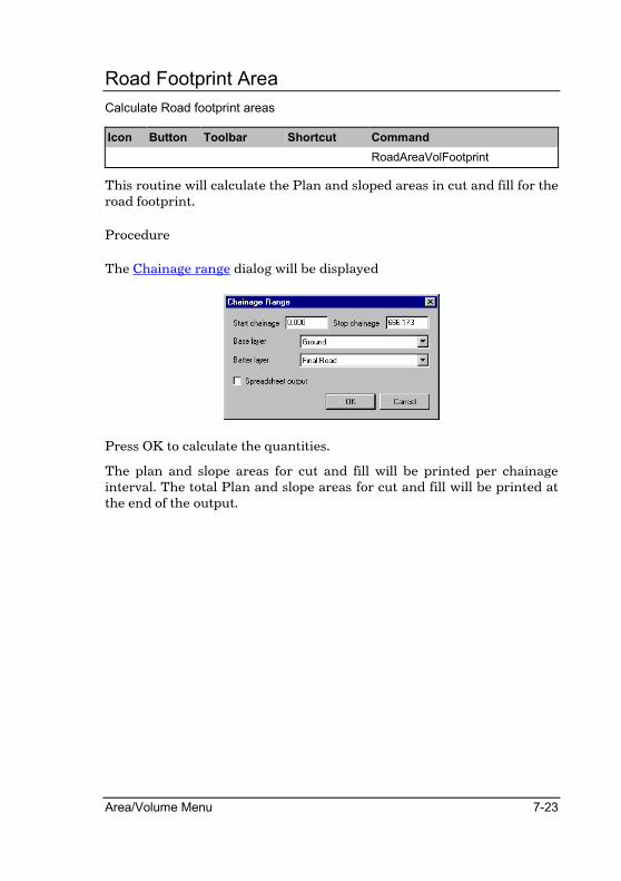
Area/Volume Menu 7-23
Road Footprint Area
Calculate Road footprint areas
Icon Button Toolbar Shortcut Command
RoadAreaVolFootprint
This routine will calculate the Plan and sloped areas in cut and fill for the road footprint.
Procedure
The Chainage range dialog will be displayed
Press OK to calculate the quantities.
The plan and slope areas for cut and fill will be printed per chainage interval. The total Plan and slope areas for cut and fill will be printed at the end of the output.

7-24 Roads Reference
Use Index
Carry out area calculation as defined in the road index
Icon Button Toolbar Shortcut Command
RoadAreaVolUseIndex
This routine is used for reruns if sectional areas have been taken out previously. Whatever condition you originally applied to a particular chainage stretch will be duplicated. In this way, areas can be run over long stretches with a variety of different templates, batter slopes etc. without the necessity of having to re-specify the individual conditions.
The Area Indicator value in the index controls the way the banks will be created. The indicator values, batter slopes and template numbers used are those recorded by the last area calculation. They could also have been edited or manually entered in the Index item under Tools.
Once a profile has been generated with a template and then individually modified in some way, it is a good idea to 'lock' it by setting the index indicator to '2'. This means that any reruns will only adjust the batters and never interfere with the center portion of the section.
Procedure
The Chainage Range dialog is displayed.
Fill in the relevant data and click the [OK] button to continue. The Output Manager dialog is displayed in order for you to set output options. Click the [OK] button to accept the settings.
If you selected the Spreadsheet output option, then Windows’ standard save dialog is displayed in order for you to select a file to which to write. The drive and path automatically default to the last used drive and directory for this type of file.

Area/Volume Menu 7-25
Masshaul Volume
Calculate masshaul volumes from cross section areas
Icon Button Toolbar Shortcut Command
RoadAreaVolMassHaulVolume
This routine calculates volumes yielding a normal Masshaul with the imbalance between cut and fill as a result. The calculation may be broken into stretches with varying compaction factors and topsoil stripping depths, but yields a final global volume at the end.
End areas from one of the area routines must have been obtained before it is possible to get answers from this routine.
A starting volume can be added to the overall run to allow for arbitrary items such as borrowed material, bellmouths, culverts etc. A starting chainage is also given. Thereafter the routine will cycle asking for a depth of topsoil stripping, compaction factor and end chainage for each stretch. The volumes for each stretch will be listed as they are calculated.
The compaction value applies to cut quantities and is in percent. A value of less than 100 gives compaction and greater than 100 gives bulking. The topsoil depth applies to the depth of material that will be removed from the entire prism width of the road.
When the end chainage is reached, the option to print the final results should be selected. Note that the Output Window should be open.
The results of this routine may optionally be stored in a Spreadsheet for subsequent analysis.
See also Cumulative Volumes for an alternative calculation.
Procedure
The Volume Calculation Details dialog is displayed.

7-26 Roads Reference
Start chainage Enter the first chainage of the range of chainages for which volumes should be calculated.
Stop chainage Enter the last chainage of the range of chainages for which volumes should be calculated.
Start volume Enter the volume that should be added to the overall run to accommodate arbitary items such as borrow material, bellmouths, culverts, etc.
Topsoil to strip Enter the depth of topsoil that should be stripped from cross sections before volumes are calculated.
Bulking/Compaction factor Enter the bulking or compaction factor that should be applied to calculated cut volumes. Factors of over 100 imply bulking while factors under 100 imply compaction. A value of 100 will ignore any form of bulking or compaction.
Batter layer Select the layer for which volumes should be calculated.
Spreadsheet output Check this option to have the results of this function written out in comma-delimited format suitable for importing into a spreadsheet.
Print Results Button Click this button to print the final result of the volume calculation. This button is activated after volumes for the first defined range have been calculated.
Fill in the relevant data and click the [OK] button to continue.
If you selected the Spreadsheet output option, then Windows’ standard save dialog is displayed in order for you to select a file to which to write. The drive and path automatically default to the last used drive and directory for this type of file.
The Output Manager dialog is displayed in order for you to set output options. Click the [OK] button to accept the settings.
Calculations for the first defined range are carried out. The Volume Calculation Details dialog is then redisplayed. The start chainage defaults to the end chainage of the previous range. You may now enter a new end chainage, change the topsoil stripping depth and/or change the Bulking/Compaction factor. Fill in the relevant data and click the [OK] button to continue, or click the [Print Results] button to end the function.
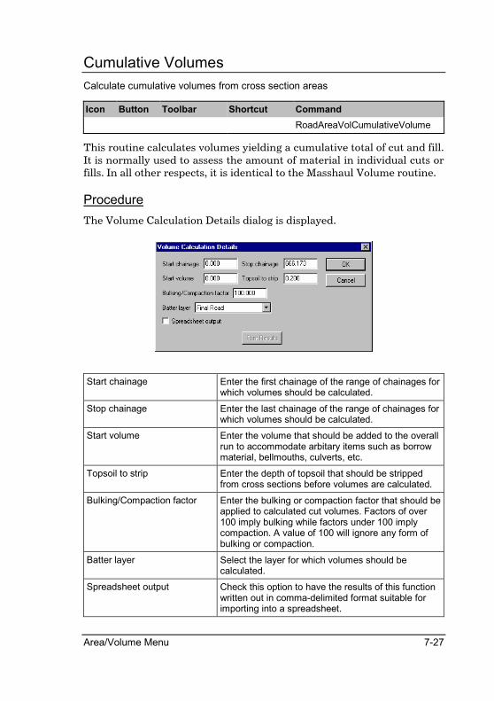
Area/Volume Menu 7-27
Cumulative Volumes
Calculate cumulative volumes from cross section areas
Icon Button Toolbar Shortcut Command
RoadAreaVolCumulativeVolume
This routine calculates volumes yielding a cumulative total of cut and fill. It is normally used to assess the amount of material in individual cuts or fills. In all other respects, it is identical to the Masshaul Volume routine.
Procedure
The Volume Calculation Details dialog is displayed.
Start chainage Enter the first chainage of the range of chainages for which volumes should be calculated.
Stop chainage Enter the last chainage of the range of chainages for which volumes should be calculated.
Start volume Enter the volume that should be added to the overall run to accommodate arbitary items such as borrow material, bellmouths, culverts, etc.
Topsoil to strip Enter the depth of topsoil that should be stripped from cross sections before volumes are calculated.
Bulking/Compaction factor Enter the bulking or compaction factor that should be applied to calculated cut volumes. Factors of over 100 imply bulking while factors under 100 imply compaction. A value of 100 will ignore any form of bulking or compaction.
Batter layer Select the layer for which volumes should be calculated.
Spreadsheet output Check this option to have the results of this function written out in comma-delimited format suitable for importing into a spreadsheet.

7-28 Roads Reference
Print Results Button Click this button to print the final result of the volume calculation. This button is activated after volumes for the first defined range have been calculated.
Fill in the relevant data and click the [OK] button to continue.
If you selected the Spreadsheet output option, then Windows’ standard save dialog is displayed in order for you to select a file to which to write. The drive and path automatically default to the last used drive and directory for this type of file.
The Output Manager dialog is displayed in order for you to set output options. Click the [OK] button to accept the settings.
Calculations for the first defined range are carried out. The Volume Calculation Details dialog is then redisplayed. The start chainage defaults to the end chainage of the previous range. You may now enter a new end chainage, change the topsoil stripping depth and/or change the Bulking/Compaction factor. Fill in the relevant data and click the [OK] button to continue, or click the [Print Results] button to end the function.

Area/Volume Menu 7-29
Layerwork Volumes
Calculate volumes of template layerworks
Icon Button Toolbar Shortcut Command
RoadAreaVolLayerworkVolume
This routine calculates the volumes of layerworks that have been included in the template(s) applied to the active road.
The layerworks must be consistent throughout the chainage run that you want to calculate. If this is not the case, the routine will halt with an error message.
The Cut and fill volumes for each layer will be calculated. The Cut and fill preperation area for each laye will also be calculated.
Procedure
The Layerworks dialog is displayed.

7-30 Roads Reference
Start chainage Enter the first chainage of the range of chainages to process.
Stop chainage Enter the last chainage of the range of chainages to process.
Batter layer Select the layer for which volumes must be calculated. This layer must have been generated from a template which has defined layerworks.
Fill in the relevant details and click the [OK] button to continue.
The Output Manager dialog is displayed in order for you to set output options. Click the [OK] button to accept the settings.

Pipe Menu 8-1
Pipe Menu
The Pipe Menu allows you to generate Pipe long sections very easily using three systems:
• Auto Manholes – generates a long section using defined manholes
• Auto Lengths – calculates the levels at the inlet and outlet of pipes of a specified length
• Parallel pipes – calculates the levels of a pipe that follows the ground line with a specified cover
You can also calculate trench volumes by depth increment.

8-2 Roads Reference
Edit Alignment
Edit a pipe alignment
Icon Button Toolbar Shortcut Command
RoadPipeEditAlignment
This routine may be used to enter a new alignment or to edit an existing alignment.
Bend point data is entered in the spreadsheet by typing the Name, Chainage, Invert In, Invert Out and a Type indicator (1 for a manhole, 0 for a bend). Invert In and Invert Out allow for drop inverts in pipes and only apply to manholes. If Invert Out is set to 0, then it will automatically take on the Invert In level.
At any manhole, Invert In is always the invert level coming in from (or going out to) the manhole on the left of this one. Invert Out is always the invert level going out to (or coming in from) the manhole on the right of this one.
The vertical alignment is stored in ASCII format in the design file of the active road file.

Pipe Menu 8-3
Graphical Insert
Graphically insert a bend point in a pipe alignment
Icon Button Toolbar Shortcut Command
RoadPipeGraphicalInsert
This routine is used to insert a bend point into a pipe alignment.
Procedure
The following prompt is displayed:
Indicate position for new bend point
Click on a position in the Road window and a bend point is inserted in the pipe alignment at the current offset and elevation.

8-4 Roads Reference
Graphical Delete
Graphically delete a bend point in a pipe alignment
Icon Button Toolbar Shortcut Command
RoadPipeGraphicalDelete
This routine is used to delete a bend point or manhole from a pipe alignment.
Procedure
The following prompt is displayed:
Indicate bend point to delete
Click on a bend point (or manhole) in the pipe alignment and the following message is displayed:
Click the [Yes] button to delete the indicated alignment point, or click the [No] button to retain the point.

Pipe Menu 8-5
Graphical Edit
Graphically indicate a bend point to edit in a pipe alignment
Icon Button Toolbar Shortcut Command
RoadPipeGraphicalEdit
This routine is used to edit a bend point or manhole in a pipe alignment.
When you change any of the Chainage, Invert In, Invert Out, In Slope or Out Slope values, the other values will automatically be calculated when you tab off the edit box or when clicking [OK]. For example, if you change the In Slope value, the Invert In value will be updated.
Procedure
The following prompt is displayed:
Indicate bend point to edit
Click on a bend point (or manhole) in the pipe alignment and the Node Details dialog is displayed.
Chainage Enter the chainage of this node.
Invert in Enter the incoming invert level of this node. The pipe from the manhole or bend to the left of this one enters this node at this level.
Invert out Enter the outgoing invert level of this node. The pipe from the manhole or bend to the right of this one enters this node at this level. Only available if Node type is set as Manhole. Enter a different level to the incoming invert level for a drop manhole. An entry of 0 will automatically take on the incoming invert level.
In Slope Enter the slope of the pipe, in percentage, entering the manhole or bend.

8-6 Roads Reference
Out Slope Enter the slope of the pipe, in percentage, exiting the manhole or bend.
Node type Select either Bend or Manhole to specify whether this node is to be processed as a bend or as a manhole.
Manhole name Enter the name of this manhole. Only available if Node type is set as Manhole.
Fill in the relevant data and click the [OK] button to continue.

Pipe Menu 8-7
Graphical Move
Graphically move a bend point to edit in a pipe alignment
Icon Button Toolbar Shortcut Command
RoadPipeGraphicalMove
This routine is used to move a bend point or manhole in a pipe alignment.
Procedure
The following prompt is displayed:
Indicate bend point to move
Click on a point in the pipe alignment and the following prompt is displayed:
Indicate new position for bend point
Click on a position in the Road window and the bend point is updated to the new offset and invert level. The revised alignment is displayed as the mouse is moved. Right click the mouse or press [Esc] to cancel the move before the second click.

8-8 Roads Reference
Ground Lines
Display additional long sections in a pipe alignment
Icon Button Toolbar Shortcut Command
RoadPipeGroundLines
This routine is used to specify ground line long sections to display in addition to the normal ground line.
Procedure
The Ground Line Details dialog is displayed.
On – Line 2 to Line 4 Check this option to turn on the display of the selected line.
Layer – Line 2 to Line 4 Select the layer from which the long section should be extracted.
Pen Button – Line 1 to Line 4 Click this button to select the pen in which the selected line should be drawn.
Fill in the relevant data and click the [OK] button to continue.
Pipe Menu 8-9
Review Alignment
List pipe alignment data
Icon Button Toolbar Shortcut Command
RoadPipeReviewAlignment
This function produces a detailed listing of the pipeline details.
Each bend point is listed with its invert level, the grade of the pipe between this point and the next, the length from bend point to bend point and the total or accumulated length up to this point. In the case of a drop invert, the second invert is listed directly below the first.
Make sure the Output Window is open to see the listing on the screen.
Procedure
The Output Manager dialog is displayed in order for you to set output options. Click the [OK] button to accept the settings.

8-10 Roads Reference
Auto Manholes
Auto-generate a pipe alignment using manholes
Icon Button Toolbar Shortcut Command
RoadPipeAutoManholes
This function permits the rapid insertion and visible display of manhole and pipe details.
To use the routine it is essential that the long section should have been collected from named bend points with Terrain ► Long Section ► Extract.
When the routine is selected, you are prompted to enter the layer to be used for the ground layer. For every manhole on the pipeline, a dialog box prompts for an invert level or the depth below the ground level.
To view the line, click the Redraw icon in the Roads window. The pipeline created will then be displayed on the screen. It will be noted that a secondary line, the minimum cover depth below the ground, will appear as an aid to further editing.
The long section may now be edited by using the graphical routines or by editing the data in the spreadsheet.
Select Review Alignment to list alignment details.
Procedure
The Layer Details dialog is displayed.
Fill in the relevant data and click the [OK] button to continue.
If there is an existing pipe alignment the following message is displayed:

Pipe Menu 8-11
Click the [Yes] button to overwrite the existing alignment with the new alignment, or click the [No] button to cancel the function.
For each of the named points in the extracted long section the Bend Invert Details dialog is displayed.
Bend point invert Select either the Invert level or Depth below ground option. This will define the invert level for this bend point by an entered level or by an entered depth below ground level.
Fill in the relevant data and click the [OK] button to continue.
8-12 Roads Reference
Auto Lengths
Auto-generate a pipe alignment using pipe lengths
Icon Button Toolbar Shortcut Command
RoadPipeAutoLengths
This routine permits you to set a start point, a length of pipe and a minimum ground cover. The routine will create a run of manholes at that minimum cover where each one is separated from the next by the sloped length that has been set.
The start point can be either a new chainage or a continuation from the last point entered. When selecting to start from a chainage, you also have to enter a starting invert level that corresponds to this chainage.
The layer to be used for the ground layer, the pipe length and a minimum depth must to be entered. The routine will then generate invert levels and grades using these criteria.
To view the pipeline, click the Redraw icon in the Roads window. The pipeline generated will then be displayed on the screen. It will be noted that a secondary line, the minimum cover depth below the ground, will appear as an aid to further editing.
The long section may now be edited by using the graphical routines or by editing the data in the spreadsheet. Select Review Alignment to list alignment details.
Procedure
The Auto Generate Details dialog is displayed.

Pipe Menu 8-13
Generate from Select either the Chainage option to start from a specific chainage or the Continue from last point option to continue from the last point currently entered in the Pipe spreadsheet.
Elevation Enter the starting elevation of the entered chainage. Only available if selecting to generate from a chainage.
Ground layer Select the layer that contains the ground longsection.
Minimum depth to invert Enter the minimum depth below ground level of the pipe invert.
Pipe length Enter the length of pipe to be used in generation.
Fill in the relevant data and click the [OK] button to continue.
The following message is displayed:
Click the [Yes] button to add to the existing pipe data, click the [No] button to overwrite the existing alignment, or click the [Cancel] button to cancel the function.

8-14 Roads Reference
Parallel Pipes
Auto-generate a pipe alignment parallel to the ground line
Icon Button Toolbar Shortcut Command
RoadPipeParallelPipes
This routine simply creates a pipeline a set depth below the ground. The line “hugs” the ground and is therefore suitable for pressure mains, irrigation lines, etc. A multitude of pipe lengths is created and it is normal to graphically delete many of them immediately after creation.
The minimum depth below the ground line, the layer to be used for the ground layer and the chainage to start from has to be entered. The routine will then generate invert levels and grades that follow the natural ground line of the section.
To view the pipeline, click the Redraw icon in the Roads window. The pipeline generated will then be displayed on the screen. It will be noted that a secondary line, the minimum cover depth below the ground, will appear as an aid to further editing.
The long section may now be edited by using the graphical routines or by editing the data in the spreadsheet.
Select Review Alignment to list alignment details.
Procedure
The Parallel Pipeline Details dialog is displayed.
Depth below ground level for pipes
Enter the depth that the pipes should be placed below ground level.
Ground layer Select the layer that contains the ground longsection.
Extract from chainage Enter the chainage from which pipe generation should begin.

Pipe Menu 8-15
Fill in the relevant data and click the [OK] button to continue. The following message is displayed:
Click the [Yes] button to add to the existing pipe data, click the [No] button to overwrite the existing alignment, or click the [Cancel] button to cancel the function.

8-16 Roads Reference
Manhole Data
Edit data for the manholes in the pipe alignment
Icon Button Toolbar Shortcut Command
RoadPipeManholeData
This routine allows you to enter ancillary data for the pipeline. This data is used for plotting purposes only.
The first two columns of this spreadsheet are automatically updated when the long section is generated.
You may update the remainder of the data for plotting purposes.
Flow information is not calculated by this routine. Should you wish to have flow information calculated then you should use the Sewer, Storm or Water modules of Civil Designer.
Procedure
The Pipe Manhole Details dialog is displayed.
Manhole column Enter the name of the manhole.
Cover column Enter the cover level of the manhole.
Diam. Column Enter the manhole diameter for plotting purposes.

Pipe Menu 8-17
Pipe column Enter the diameter of the pipe for plotting purposes.
Capac. Column Enter the flow capacity of the pipe for plot labeling purposes. Note that this value is NOT calculated in any way.
Veloc. Column Enter the flow velocity of the pipe for plot labeling purposes. Note that this value is NOT calculated in any way.
User 1 column Enter a user-defined value for plot labeling purposes.
User 2 column Enter a user-defined value for plot labeling purposes.
Fill in the relevant data and click the [OK] button to continue.

8-18 Roads Reference
Invert Levels
List invert levels for the pipe alignment
Icon Button Toolbar Shortcut Command
RoadPipeInvertLevels
This routine produces a listing of chainages and corresponding invert levels.
To view the listing on the screen, make sure the Output Window is open.
Procedure
The Output Manager dialog is displayed in order for you to set output options. Click the [OK] button to accept the settings.

Pipe Menu 8-19
Trench Volumes
Calculate pipe trench volumes
Icon Button Toolbar Shortcut Command
RoadPipeTrenchVolume
This function calculates the earthworks volume for the pipeline trench broken up into various material types and for different pay depths.
You need to enter a start and end point name, the layer to use as a ground layer, the layers on which the various types of material are stored, the trench width and the layer the pipeline invert is to be stored in. You also have the option of setting pay depth increments for calculation. Note that the entry is in increments and not actual depths.
After the information is entered, the routine produces a listing of volumes for each depth increment from manhole to manhole.
Procedure
The Trench Volumes dialog is displayed.
Start name Enter the name of the manhole at which to start the volume calculation.
Stop name Enter the name of the manhole at which to stop the volume calculation.
Ground layer Select the layer that contains the ground long section.
Hard layer Check this option and select the layer that contains the hard material long section if you wish to have hard material volumes included in the calculation.

8-20 Roads Reference
Rock layer Check this option and select the layer that contains the rock material long section if you wish to have rock material volumes included in the calculation.
Trench layer Select the layer on which the trench cross sections should be placed.
Trench width Enter the overall width of the trench.
Set Depths Button Click this button to set the pay depth increments for the calculation.
Fill in the relevant data and click the [OK] button to continue.
In the Trench Volumes dialog you can click the [Set Depths] button to display the Depth Categories dialog for setting up pay depth increments.
Fill in the depth increments you require and click the [OK] button to continue. The Output Manager dialog is displayed in order for you to set output options. Click the [OK] button to accept the settings. The following message is displayed:
Click the [Yes] button to overwrite any existing data on the selected trench layer, or click the [No] button to continue with the calculation but not to store the calculated trench layer.

Tools Menu 9-1
Tools Menu
The Tool Menu contains functions to manipulate the road index, do construction checks on the road, calculate precise levels at intersections, create and edit road templates and insert long and short chains into the road.

9-2 Roads Reference
Index
The basic structure of a roads database is called the index. These routines allow editing and manipulations for that structure.
The Index comprises a series of records that each contains a number of fields. There are two types. Chainage records and Surface records. At each cross section location on the road, there will be one chainage record that contains the details about that particular position on the road. At the same location there may be up to 128 surface records.
Once this data is available in the index, you can perform re-runs just by drawing off this information. However, because you can edit and
alter any of the items in the Index, a fully customizable road can be set up. For example, localized special slope conditions, frozen batters, switched off portions over bridges, allowances for daylighting and a variety of other circumstances.
Chainage Record
Each chainage has a coordinate (probably) and a switched 'on or off' flag. It also knows which chainage came before it, which one will come next, and which layers have been acquired at that location.
Then, at every chainage, each layer carries certain data items. These are the batter slopes, minimum bank lengths and indicators. By default, these items are added automatically.
So if you list a set of freshly produced design sections, you will find that all the values are shown as 0s. After applying a template in the Area/Volumes menu, a listing will now show slopes and indicators with the relevant values in place.
A Chainage record contains the following fields:
Chainage the actual chainage value.
H Ordinate the horizontal ordinate for the chainage point.
V Ordinate the vertical ordinate for the chainage point.
Skew the angle from the normal for cross section extraction.
On/Off flag enables the chainage to become invisible to routines. A value of '1' switches the chainage off.

Tools Menu 9-3
The On / Off flag enables a chainage to become invisible to routines. By default, every chainage is visible so a value of "1" switches the chainage off and "0" switches it on.
Layer Record
Each layer record contains the information that control the way areas are formed with that layer. Most options in the Road menu will retrieve certain items from the index and write others into it.
If the Use Index option is chosen in the Area/Volume functions then all the required items are retrieved. As an example, by editing the template number a different template would be applied and by changing the batter flag from '1' to '0', new batters would be appended to the existing ones, and so on. It should be remember that layer 128 is reserved for the long section elevations.
A Layer record contains the following fields:
Area Indicator the type of areas calculated in Area/Volume when this layer was last used as the batter layer. (See below)
Template Number the template number set in Alignment � Edge Levels when edge levels were generated for this layer.
User Code reserved for future use.
Batter Flag flag to indicate that batters are present. (See note below)
Left Cut Slope of left cut batter (1:nn).
Left Fill Slope of left fill batter (1:nn).
Right Cut Slope of right cut batter (1:nn).
Right Fill Slope of right fill batter (1:nn).
Left Cut min offset from CL for the toe of the left cut batter.
Left Fill min offset from CL for the toe of the left fill batter.
Right Cut min offset from CL for the toe of the right cut batter.
Right Fill min offset from CL for the toe of the right fill batter
If the Batter Flag is set to '1' then batters are assumed to be present and would first be removed and then re-calculated when areas are run in Area/Volume. If set to '0' then it is assumed batters are absent and when areas are run, new batters will be appended to the extremities of the cross section as it stands.

9-4 Roads Reference
The Area Indicator value controls the way the banks will be created:
0 Will bypass the section altogether
1 A normal template addition.
2 Calculates batters. (No template added)
3 A dump calculation (Base connection)
4 Forces a join of the layer extremities
5 A dam calculation
6 An area calculation only
The indicator values, batter slopes and template numbers used are those recorded by the last area calculation.
In the same way as Survey Editing makes fundamental changes to the terrain database, the Index functions can have serious repercussions on the road data. It is recommended that before making any changes you backup the relevant road data file manually.

Tools Menu 9-5
List Chainage Records
List the data from chainage records
Icon Button Toolbar Shortcut Command
RoadIndexListChainageRecords
This routine produces a listing of the chainage records in the road database.
A start and stop chainage must be provided and all records in the selected range will be listed.
Procedure
The Chainage Range Details dialog is displayed.
Start chainage Enter the first chainage of the range of chainages to process.
Stop chainage Enter the last chainage of the range of chainages to process.
Current layer Select the layer that should be processed. Availability depends on the process being carried out.
Destination layer Select the layer to which the processing results should be written. Availability depends on the process being carried out.
Fill in the relevant data and click the [OK] button to continue.
The Output Manager dialog is displayed in order for you to set output options. Click the [OK] button to accept the settings.

9-6 Roads Reference
Edit Chainage Record
Edit the data from chainage records
Icon Button Toolbar Shortcut Command
RoadIndexEditChainageRecord
This routine enables the editing of the fields for a chainage record.
To locate a particular chainage record, the value may be typed in the chainage box and the [Find] button clicked or the scroll bar may be used. For a change to be recorded the [Save] button must be clicked.
Procedure
The Chainage Record Edit dialog is displayed.
Find Click this button to search for the current Chainage entry.
Chainage Enter the chainage that should be found.
Previous chainage Click this button for the previous chainage in the road database (if any).
Next chainage Click this button for the next chainage in the road database (if any).
Scrollbar Click on the scrollbar to scroll through the chainage records in the database.
Y Coord Enter the horizontal ordinate of the chainage record.
X Coord Enter the vertical ordinate of the chainage record.
Section skew Enter the skew angle at which cross sections should be extracted for this chainage record.
Switch chainage off Check this option to make this chainage invisible to normal section processing functions.
Fill in the relevant data and click the [Save] button to save changes. Click the [Close] button to end the function.

Tools Menu 9-7
Set Chainage Fields
Set specific chainage field values
Icon Button Toolbar Shortcut Command
RoadIndexSetChainageRecord
This routine allows for the setting of one of the chainage fields to a particular value.
The field to be set must be selected and the value it should be set to must be entered. A start and stop chainage for the records to be altered must also be provided. A common use would be to 'close off' a series of chainages by setting the On/Off flag to '1'
Procedure
The Chainage Field Editing dialog is displayed.
Field to set Select the chainage field for which the value should be set.
Value to set Enter the value to which the selected field should be set.
Fill in the relevant data and click the [OK] button to continue.
The Chainage Range Details dialog is displayed.

9-8 Roads Reference
Start chainage Enter the first chainage of the range of chainages to process.
Stop chainage Enter the last chainage of the range of chainages to process.
Current layer Select the layer that should be processed. Availability depends on the process being carried out.
Destination layer Select the layer to which the processing results should be written. Availability depends on the process being carried out.
Fill in the relevant data and click the [OK] button to continue.
The Output Manager dialog is displayed in order for you to set output options. Click the [OK] button to accept the settings.

Tools Menu 9-9
Batch On/Off Switch
Switch a batch of chainages on or off
Icon Button Toolbar Shortcut Command
RoadIndexBatchSwitch
This routine is used to switch a number of chainages in the road database on or off.
A start and stop chainage must be provided and an interval between the chainages to switch.
This permits parts of a road to be rendered 'invisible'. By incorporating an interval that is not the original coordination interval, every alternate (or third, fourth or fifth) chainage can be switched on or off. This is useful for temporarily increasing the density of sections in a particular area such as tight curves.
Procedure
The Batch Chainage On/Off Switch dialog is displayed.
Start chainage Enter the first chainage of the range of chainages to process.
Stop chainage Enter the last chainage of the range of chainages to process.
Chainage interval Enter the interval between chainages to process.
Switch chainage Select whether to make the chainages visible (On) or invisible (Off) to other processing functions.
Fill in the relevant data and click the [OK] button to proceed.
The Output Manager dialog is displayed in order for you to set output options. Click the [OK] button to accept the settings.

9-10 Roads Reference
List Layer Records
List data from layer records
Icon Button Toolbar Shortcut Command
RoadIndexListSurfaceRecords
This routine produces a listing of the layer records between two chainages for a selected layer.
A start and stop chainage must be entered as well as the layer to list.
Procedure
The Chainage Range Details dialog is displayed.
Start chainage Enter the first chainage of the range of chainages to process.
Stop chainage Enter the last chainage of the range of chainages to process.
Current layer Select the layer that should be processed. Availability depends on the process being carried out.
Destination layer Select the layer to which the processing results should be written. Availability depends on the process being carried out.
Fill in the relevant data and click the [OK] button to continue.
The Output Manager dialog is displayed in order for you to set output options. Click the [OK] button to accept the settings.

Tools Menu 9-11
Edit Layer Records
Edit data from layer records
Icon Button Toolbar Shortcut Command
RoadIndexEditSurfaceRecord
This routine allows you to edit any of the fields for any one particular layer record.
The layer to edit must be selected. To locate a particular layer record, the value may be typed in the chainage box and the [Find] button clicked or the scroll bar may be used. For a change to be recorded the [Save] button must be clicked.
Procedure
The Layer Edit dialog is displayed.
Specify which layer to edit and click the [OK] button to continue.
The Layer Record Edit dialog is displayed.
Find Click this button to find the entered chainage.
Chainage Enter the chainage to be found.
Previous chainage Click this button for the previous chainage in the road database (if any).

9-12 Roads Reference
Next chainage Click this button for the next chainage in the road database (if any).
Scrollbar Click on the scrollbar to scroll through the layer records in the database.
Area indicator Enter a value (0 to 6) to indicate the type of areas last calculated (See Road INDEX Technical and Road INDEX General).
Template number Enter the template number to use with this section.
User code This entry is not used by any functions and therefore is available for any entry.
Batter flag Set to 1 if batters are present (and will therefore be removed and recalculated when areas are run) otherwise set to 0 to indicate that no batters are present (and will therefore be added on when areas are run).
Batter slopes Enter the relevant batter slopes as 1:x.
Min. batter offsets Enter the minimum offset from the centreline to the relevant batter toe.
Save Click this button to save the current entries in the dialog.
Close Click this button to end the function.
Fill in the relevant data and click the [OK] button to continue.

Tools Menu 9-13
Set Layer Fields
Set specific layer field values
Icon Button Toolbar Shortcut Command
RoadIndexSetSurfaceField
This option provides for the setting of one of the layer fields in all the layer records over a specified chainage range.
The field to be set must be selected and the value it should be set to must be entered. A start and stop chainage as well as the layer for the records to be altered must also be provided.
Procedure
The Layer Field Editing dialog is displayed.
Field to set - Various Select the field for which the entered value should be set.
Value to set Enter the value to which the selected field should be set.
Fill in the relevant data and click the [OK] button to continue.
The Chainage Range Details dialog is displayed.

9-14 Roads Reference
Start chainage Enter the first chainage of the range of chainages to process.
Stop chainage Enter the last chainage of the range of chainages to process.
Current layer Select the layer that should be processed. Availability depends on the process being carried out.
Destination layer Select the layer to which the processing results should be written. Availability depends on the process being carried out.
Fill in the relevant data and click the [OK] button to continue.
The Output Manager dialog is displayed in order for you to set output options. Click the [OK] button to accept the settings.
Tools Menu 9-15
Transfer Layer Fields
Transfer specific layer field values between layers
Icon Button Toolbar Shortcut Command
RoadIndexTransferSurfaceFields
This option allows the values of selected fields to be transferred from one layer to another.
This is particularly useful where manual adjustments have been made to bank slopes and a subsequent layer has to be created with the identical edge conditions (e.g. monthly progress measurements). The field or fields to transfer must be selected followed by a start and stop chainage and the layers to transfer the fields between.
Procedure
The Layer Field Transfer dialog is displayed.
Fields to transfer Select the fields that should be transferred between layers
Fill in the relevant data and click the [OK] button to continue. The Chainage Range Details dialog is displayed.
Start chainage Enter the first chainage of the range of chainages to process.
Stop chainage Enter the last chainage of the range of chainages to process.

9-16 Roads Reference
Current layer Select the layer that should be processed. Availability depends on the process being carried out.
Destination layer Select the layer to which the processing results should be written. Availability depends on the process being carried out.
Fill in the relevant data and click the [OK] button to continue.
The Output Manager dialog is displayed in order for you to set output options. Click the [OK] button to accept the settings.

Tools Menu 9-17
Batter Slope Extraction
Set the layer batter field values to that of the cross section data
Icon Button Toolbar Shortcut Command
RoadIndexBatterExtraction
This option enables the slope of existing batters to be extracted and inserted in the relevant fields in the layer record. It is used in situations where sections have been generated by means other than the area program, or where they have been manually edited but the batter slope details are now required for area calculations.
A typical example would be sections extracted across a terrace at an odd angle. Due to the angle the bank slopes will vary from the normal 1:1.5 or 1:2 of the terrace. This routine would then be used to obtain the slopes.
A start and stop chainage must be entered as well as the layer for which the batters should be calculated. The batter slopes will then be added to the layer records. This routine automatically sets the Area Indicator to indicate a normal batter calculation ('2') and the Batter flag will be set to indicate that batter slopes are present ('1').
Procedure
The Chainage Range Details dialog is displayed.
Start chainage Enter the first chainage of the range of chainages to process.
Stop chainage Enter the last chainage of the range of chainages to process.
Current layer Select the layer that should be processed. Availability depends on the process being carried out.
Destination layer Select the layer to which the processing results should be written. Availability depends on the process being carried out.

9-18 Roads Reference
Batter Slope Adjustment
Apply a constant change to batter slopes
Icon Button Toolbar Shortcut Command
RoadIndexBatterAdjustment
This function allows you to add a constant to the batter slopes or multiply batter slopes between two chainages in the section file by a constant. A typical use would be for "daylighting" sections.
Procedure
The Chainage Range Details dialog is displayed.
Start chainage Enter the first chainage of the range of chainages to process.
Stop chainage Enter the last chainage of the range of chainages to process.
Current layer Select the layer that should be processed. Availability depends on the process being carried out.
Destination layer Select the layer to which the processing results should be written. Availability depends on the process being carried out.
Fill in the relevant data and click the [OK] button to continue.
The Layer Batter Adjustment dialog is displayed.

Tools Menu 9-19
Process - Left and Right cut and fill slope
Select any combination of the batter slopes to be processed.
Function - Add or Multiply Select whether the entered value should be added to the batter slope or if the batter slope should be multiplied by it.
Function - Value Enter the value with which batter slopes should be adjusted.
Fill in the relevant data and click the [OK] button to continue.
The Output Manager dialog is displayed in order for you to set output options. Click the [OK] button to accept the settings, or click the [Cancel] button to use the previous settings.

9-20 Roads Reference
Delete Chainage
Delete a specified chainage from the index
Icon Button Toolbar Shortcut Command
RoadIndexDeleteChainage
This routine is used to remove a chainage record and all the layer records linked to it from the road database.
The chainage to be deleted must be entered and it is then removed from the index.
Deleting a chainage means that ALL associated cross sections for the chainage will be deleted and cannot be recovered.
Procedure
The Output Manager dialog is displayed in order for you to set output options. Click the [OK] button to accept the settings.
The Chainage Deletion dialog is displayed.
Specify the chain to delete and click the [Delete] button to continue.

Tools Menu 9-21
Batch Chainage Deletion
Delete a range of chainages from the index
Icon Button Toolbar Shortcut Command
RoadIndexBatchDelete
This routine is used to delete a number of chainages in the road database.
A start and stop chainage must be provided. The entire range of chainage records will be deleted from the road index.
Deleting a chainage means that ALL associated cross sections for the chainage will be deleted and cannot be recovered.
Procedure
The Chainage Range Details dialog is displayed.
Start chainage Enter the first chainage of the range of chainages to process.
Stop chainage Enter the last chainage of the range of chainages to process.
Current layer Select the layer that should be processed. Availability depends on the process being carried out.
Destination layer Select the layer to which the processing results should be written. Availability depends on the process being carried out.
Fill in the relevant data and click the [OK] button to continue.
The Output Manager dialog is displayed in order for you to set output options. Click the [OK] button to accept the settings.

9-22 Roads Reference
Insert Chainage
Insert a new chainage into the index
Icon Button Toolbar Shortcut Command
RoadIndexInsertChainage
This routine is used to insert individual chainages into the road database.
The chainage value to insert must be entered and a chainage record for the chainage will then be created in the road index. All the fields in the chainage record (except the chainage field) will be initialized to '0'. Therefore inserting a new chainage does not automatically mean that it has a coordinate value or any layer data. This data can be generated using the respective Road menu functions, in particular Alignment ►
Horizontal ► Coordinate with the Chainages from index option selected in order to calculate chainage coordinates.
Procedure
The Output Manager dialog is displayed in order for you to set output options. Click the [OK] button to accept the settings.
The Chainage Insertion dialog is displayed.
Specify the chain to insert and click the [Insert] button to continue.

Tools Menu 9-23
Batch Chainage Insertion
Insert a range of chainages into the index
Icon Button Toolbar Shortcut Command
RoadIndexBatchInsert
This routine is used to insert a number of chainages into the road database.
A start and stop chainage must be provided and an interval between the chainages to insert. A chainage record for each chainage at the specified interval will be created in the road database (index). All the fields in the chainage record (except the chainage field) will be initialized to '0'. You have the option of automatically interpolating centreline levels from existing cross section data.
After a pipeline longsection was extracted using Terrain ► Long Section
► Extract, levels may be interpolated at regular chainage intervals (e.g. every 10m)
If a road is to be built up over a period of time from a variety of sources, it is a good idea to use this routine at the beginning to establish a framework on which to 'hang' the whole job.
Procedure
The Chainage Range Insertion dialog is displayed.
Start chainage Enter the first chainage of the range to insert.
Stop chainage Enter the last chainage of the range to insert.
Chainage interval Enter the interval at which chainages should be generated.
Auto interpolate levels from Check this option and select a layer to have the chainage elevation interpolated from the specified layer.

9-24 Roads Reference
Graphical Insertion
Graphically insert a chainage at a skew angle.
Icon Button Toolbar Shortcut Command
RoadIndexGraphicalInsert
This routine allows you to graphical insert a chainage in the index file, straight or at a skew angle. After the chainage has been inserted, all the calculations for the newly inserted chainage will be performed automatically i.e. coordinate, extract ground sections, generate vertical levels, generate edge levels and apply the template.
Procedure
To graphically insert a chainage at a known skew angle:
The program will prompt:
Enter the skew angle, else indicate graphically
Enter the angle in degrees and press [OK]. A positive angle rotates clock-wise from the normal cross section angle.
The Program will prompt:
Indicate the position for new chainage
Graphically indicate, on the Design centre Window, the position for the new chainage.
To graphically insert a chianage at an unknown skew angle:
The program will prompt:
Enter the skew angle, else indicate graphically
Press the [Cancel] button.
The program will prompt:
Indicate a point on the new cross section, Left of the CL
Graphically indicate the position on the Design centre window to the left of the centre line where the cross section line must run through.
The program will prompt:
Indicate a point on the new cross section, Right of the CL
Graphically indicate the position on the Design centre window to the Right of the centre line where the cross section line must run through.

Tools Menu 9-25
Construction
These routines are used in the construction of roads. The data to generate information for the setting up of batter boards and final layer poles can be extracted from the design cross sections. The build up of construction layer works may also be monitored.

9-26 Roads Reference
Profile/Batters
Calculate Profile/Batter board data
Icon Button Toolbar Shortcut Command
RoadConstructionProfileBatters
This routine is used to calculate the coordinates, the height and the slope of batter boards.
Obviously, cross sections of a design layer must already exist before running this routine.
A start and stop chainage must be entered for the chainages to calculate as well as the cross section layer to be used to obtain the batter information. An offset from the toe of the batter to the front pole of the batter board must then be entered, as well as the boning distance.
For each section, the following information is listed for both left and right hand sides:
• the horizontal offset from the centreline to the front batter pole.
• the angle of the batter.
• the slope length of the batter.
• the XY co-ordinates for the front batter pole.
• the Z ordinate for the nail on the front batter pole.
The option to output this data to spreadsheet format is available.
Procedure
The Chainage Range dialog is displayed.
Fill in the relevant data and click the [OK] button to continue.

Tools Menu 9-27
The Profile/Batter Boards dialog is displayed.
Offset for profile board from batter
Enter the offset from the toe of the batter to the front pole of the batter board.
Boning distance Enter the boning distance to be used.
Fill in the relevant data and click the [OK] button to continue.
The Output Manager dialog is displayed in order for you to set output options. Click the [OK] button to accept the settings.

9-28 Roads Reference
Offset Poles
Calculate surface poles at a distance from the centreline
Icon Button Toolbar Shortcut Command
RoadIndexBatchInsert
This routine is used to generate the information necessary to control the formation of final road layers by surface poles and string lines. These poles are set at a constant distance from the centerline. Boning lines are strung between the poles at the given elevations to give the crossfall and elevation of the road layer being constructed.
A start and stop chainage must be entered for the chainages to calculate as well as the cross section layer to be used to obtain the crossfall of the road layer. A boning distance must be entered as well as a layer work depth that should be deducted from the specified cross section layer. If the cross section represents the final road layer then no deduction for layer works would be required and the value should be set to '0'.
Distances from the centreline must be given for the position of the left and right poles. There is nothing to prevent both poles being on the left or right hand sides.
For a detailed description of the boning and target distances, refer to the sketch in Relative Poles.
Procedure
The Chainage Range dialog is displayed.
Fill in the relevant data and click the [OK] button to continue.

Tools Menu 9-29
The Offset Poles dialog is displayed.
Distance from CL for poles - Left and Right
Enter the distance from the centreline at which the poles will be placed. Note that this is a distance and not an offset so that negative left values are NOT left of the centreline but rather right of it.
Distance for slope interpolation - Left and Right
Enter the target distance for the location of the plane that each string line will track. As mentioned above, note that this is a distance and NOT an offset.
Boning distance Enter the boning distance to be used.
Layer deduction Enter the layer depth to be deducted from the selected layer.
Output - List, Level 1 or Level 2
Select whether to have output as a basic table of setting out data suitable for total station work (List), as a table suitable for use as a fieldbook for direct setting out by spirit level and tape (Level 1), or as a more compact version for spirit levelling without field entries and which lists the height difference between the two nails instead of two elevations (Level 2).
Fill in the relevant data and click the [OK] button to continue.
The Output Manager dialog is displayed in order for you to set output options. Click the [OK] button to accept the settings.

9-30 Roads Reference
Relative Poles
Calculate surface poles relative to the edges of the section
Icon Button Toolbar Shortcut Command
RoadConstructionRelativePoles
This routine is used to generate the information necessary to control the formation of final road layers by surface poles and string lines. These poles are set distance from the road edge. Boning lines are strung between the poles at the given elevations to give the crossfall and elevation of the road layer being constructed.
A start and stop chainage must be entered for the chainages to calculate as well as the cross section layer to be used to obtain the crossfall of the road layer. A boning distance must be entered as well as a layer work depth that should be deducted from the specified cross section layer. If the cross section represents the final road layer then no deduction for layer works would be required and the value should be set to '0'.
An offset for the origin of the calculations must be provided. This origin is used to determine the offsets for the poles by specifying the number of cross section points left and right of the origin that the poles should be placed. The poles are then offset from the determined cross section points by the amount specified for the 'Pole Offset from Edges'.
Offsets from the centreline must be given for the interpolation of the two lines. This is a target offset for the location of the plane that each string line will track. In other words, the first point left and the first point right of the target offset will define the string line surface.
The type of listing must also be selected. One type yields a basic table of setting out data suitable for total station work. The other provides printout suitable for direct setting out by spirit level and tape.

Tools Menu 9-31
The listings provide offsets from the centreline for the poles and for each boning line, the crossfall of the layer works (%) and the elevations on the left and right pole in order to set the line. The same information is provided by all the listings - only the format varies.
As both the offset for the poles and the plane along which the interpolation of crossfall should take place are separately specified, this routine can accommodate any type of road feature, e.g. Dish drains, medians or dual carriageways. This means that the same set of poles can control several features. Dual poles (where both are on one side of the road) can also be specified.
Procedure
The Chainage Range dialog is displayed.
Fill in the relevant data and click the [OK] button to continue.
The Relative Poles dialog is displayed.

9-32 Roads Reference
Number of points L/R of origin Enter the number of points left and right of the origin to be used to determine the placement of the poles.
Pole distance from edges Enter the distance from the determined points at which the poles should be placed. Note that this is a distance and NOT an offset.
Distance for slope interpolation
Enter the target distance for the location of the plane that each string line will track.
Distance from CL for origin Enter the distance from the centreline for the origin of the point calculations.
Boning distance Enter the boning distance to be used.
Layer deduction Enter the layer depth to be deducted from the selected layer.
Output Select whether to have output as:
List A basic table of setting out data suitable for total station work
Level1 A table suitable for use as a fieldbook for direct setting out by spirit level and tape
Level2 A more compact version for spirit levelling without field entries and which lists the height difference between the two nails instead of two elevations
Fill in the relevant data and click the [OK] button to continue.
The Output Manager dialog is displayed in order for you to set output options. Click the [OK] button to accept the settings.

Tools Menu 9-33
Cross Check
Cross section level check
Icon Button Toolbar Shortcut Command
RoadConstructionCrossCheck
This routine compares the shoulders of the constructed layer against the batters of the design cross section. The purpose is to assist the monitoring of progressive excavation of earthwork build up. The horizontal difference between the offset of the constructed shoulder and the interpolated offset of the batter at the constructed level is given. This gives a quick check for over or under filling (or cutting).
A start and stop chainage must be entered for the chainages to calculate. The cross section layer to check must be entered as well as the cross section layer against which it should be compared. The layer to check should consist of cross sections of the constructed layer works from shoulder to shoulder. The layer to compare it against should be the complete cross section of the design including batters.
The data printed out for each side of the road is:
• the interpolated offset of the batter at the constructed level • the actual offset of the constructed shoulder • the difference between the two
The points compared are the first (left) and last (right) elevations on the layer being checked and matched to the theoretical distance that would yield such an elevation on the design. Therefore, the two distances must intersect.
Procedure
The Chainage Range dialog is displayed.
Fill in the relevant data and click the [OK] button to continue.

9-34 Roads Reference
Full Level Table
Full table cross section level check
Icon Button Toolbar Shortcut Command
RoadConstructionFullTable
This routine is used to monitor the elevations of constructed layer works. It produces a printout in the form of a table that may be used to compare the constructed layer work levels against the designed levels at set, predetermined positions.
A start and stop chainage must be entered for the chainages to calculate as well as the cross section layer from which to derive the levels. A list box must be filled with offsets (maximum of 10) at which levels must be interpolated from the specified cross section layer. Another list box with the required layer names and depths below the specified cross section must be completed. Up to six layer names and depths may be entered.
The tables produced will contain the design levels calculated at the specified offsets and layer work depths. Spaces are provided in the tables to manually enter the constructed elevation and the difference in level between the constructed (actual) and design (theoretical) elevations.
Once interpreted and drawn up it is often convenient to enter this table in a spreadsheet where the differences can be extracted and analyzed automatically.
Procedure
The Chainage Range dialog is displayed.
Fill in the relevant data and click the [OK] button to continue.
The Full Layer Check dialog is displayed.

Tools Menu 9-35
Offset to check Enter an offset at which the level check should be done. Offsets left of the centreline must be entered as a negative value.
Add Button Click this button to add the current offset entry into the offset list.
Remove Button Click on an entry in the offset list and then click this button to remove the highlighted entry from the list.
Layer heading Enter the heading (maximum 10 characters) that should be printed for each layer check.
Layer depth Enter the depth in millimetres that should be deducted from the layer for checking.
Add Layer Button Click this button to add the current heading and depth entries into the layer list.
Remove Layer Button Click on an entry in the layer list and then click this button to remove the highlighted entry from the list.
Fill in the relevant data and click the [OK] button to continue.
The Output Manager dialog is displayed in order for you to set output options. Click the [OK] button to accept the settings.

9-36 Roads Reference
Comparative Levels
Comparative cross section level check
Icon Button Toolbar Shortcut Command
RoadConstructionComparativeTable
This routine is used to monitor the elevations of constructed layer works. It is used to compare the levels of two layers with a tolerance check.
A start and stop chainage must be entered for the chainages to calculate. The cross section layer to check must be entered as well as the cross section layer against which to compare it. The layer to check should consist of cross sections of the constructed layer works and the layer to compare it against should be the design cross sections.
A list box must be filled with offsets (maximum of 6) at which levels must be interpolated from the specified cross section layers. A layer depth to be deducted from the layer to compare against may be entered. Tolerances for the constructed levels above and below the compared layer must also be supplied.
The output lists the offsets with the interpolated levels from both layers with the differences in level between them. The output is completed with the total number of differences calculated and the number of constructed levels falling inside and outside the specified tolerances as well as statistics about the data.
The constructed layer is frequently picked up by means of spirit leveling or tache sections from a remote station. The facilities in Survey Heighting enable the sections to be derived from these readings. Bear in mind, although the check is required at predetermined positions, there is no need for the survey point to be exactly at that spot.
Procedure
The Chainage Range dialog is displayed.

Tools Menu 9-37
Fill in the relevant data and click the [OK] button to continue. The Tolerance Check dialog is displayed.
Offset to check Enter an offset that should be checked. Offsets to the left of the centreline must be entered as a negative value.
Add Button Click this button to add the current offset entry to the offset list (maximum of 6 entries).
Remove Button Click on an entry in the offset list and then click this button to remove the highlighted entry from the list.
Level tolerance - Nominal and Maximum
Enter the tolerances for the levels of the two layers being checked. Only available if the Check layer depth option is selected.
Layer tolerance - Nominal and Maximum
Enter the tolerances for the depths between the layer being checked and the selected depth layer. Only available if the Check layer depth option is selected.
Layer depth to Select the layer for which depths between it and the layer being checked are compared. Only available if the Check layer depth option is selected.
Designed layer depth Enter the designed depth between the two selected layers. Only available if the Check layer depth option is selected.
Check layer depth Check this option if you want the depth between the layer being checked and another layer to be checked in addition to the normal level check.
Fill in the relevant data and click the [OK] button to continue.
The Output Manager dialog is displayed in order for you to set output options. Click the [OK] button to accept the settings.

9-38 Roads Reference
Intersection
The purpose of the Intersection routines is to facilitate the geometric design of road intersections in both the horizontal and vertical planes.
The data used for the geometric design is not linked to any one of the road files of the project therefore there is no need to select a road file before calculating.
Virtually all types of 'T' intersection can be handled. By putting two T' intersections back to back, it is possible to design a crossroad. By linking two T's one behind the other, cul-de-sacs can be created.

Tools Menu 9-39
New Intersection
Start a new intersection calculation
Icon Button Toolbar Shortcut Command
RoadIntersectionNew
When starting a new Intersection, there are two stages to providing the design data.
The conventions followed for the provision of design data are:
• A Main Road that may be on a curve or a straight.
• An Intersecting Road that must be on a straight.
Standing on the point of intersection of the two centrelines and looking up the intersecting road, there is a left and right side to the design. Each side is treated as a separate entity.
Stage 1 - Existing Road Design Data
The initial stage is loaded or created from the functions New Intersection or Load Intersection.
The data for this stage is entered in the Intersection Layout Details dialog.
Four coordinated (x, y & z) points defining the two road centrelines must be provided. These are the points shown as squares in the accompanying diagram and labeled:
• Main Road Left
• Main Road Right
• Point of Intersection
• Intersecting Road Centre
The Y, X and Z coordinates, the width Left and Right and grade Left and Right has to be entered for the above points. Only the coordinates have to be supplied for the Intersection point on the Main Road.

9-40 Roads Reference
L-CC Out
300R-BCOut
R-End
Point ofIntersection
A
L-Beg
L-BC In
L-BCC
L-ECCL-BC Out
L-CC
R-Beg
R-BC In
R-BCC
R-ECC
R-CC
L-End
L-CC In
140
R 25 m
R 2
0 m
Road width 'left' and 'right' in all cases is taken as viewed from the Intersection point. The calculated edges will start opposite the Intersecting Road Centre and end opposite the Main Road Left and Right points. Therefore, each of the four points should lie outside the anticipated horizontal design area. From each of these points, the road width and crossfall must also be provided. This enables the routine to establish the circled points.
These points are named:
• L-Start
• L-End
• R-Start
• R-End

Tools Menu 9-41
Stage 2 - Designed Edge Data
The data for this section is entered in the Intersection Curve Details dialog.
In this section, you will use a dialog box to provide the basic definition details for each of the left and right edges. The horizontal (plan) design can be in one of three forms.
• Simple curve
• Taper - curve - taper
• Curve - curve - curve
In the case of either of the latter two, an offset from the Intersection Point to the edge intersection is required. See the dimension lines in the illustration. The appropriate combination of curves and tapers will then be fitted.
For a Curve or Taper, the appropriate box should be checked. If the bellmouth consists of only a centre curve and no taper or lead in/out curve, uncheck both options. The appropriate input data that is required then appears non-grayed.
Tapers are specified as a '1:xx' ratio. A very flat ratio such as 1:10000 will have much the same practical effect as no taper at all.
In order to set the vertical grades at the start and end locations, the grade of the road at that point must also be provided. This grade, which is set in the % Grade sections of the main data entry dialog box, does not necessarily have to correlate to the actual road at that point. It is entered with the convention that, at every point facing into the intersection, negative grade is down and positive is up.
In other words, if the main road was at a constant grade of 5% and the left point was lower than the right, at the end point on the left side, you would put in a grade of +5%, and for the end point on the right side you would put in a grade of -5%.
It is very easy to specify impossible data for edges. This sort of problem will either be blocked at calculation time or appear in a ridiculous form on the screen plot. Therefore, every intersection should always be plotted at least once before acceptance.

9-42 Roads Reference
Procedure
The Intersection Layout Details dialog is displayed.
Intersection element Select the intersection element for which data must be entered or updated.
Name Enter the name of the selected element. If a DTM point name is entered here then the coordinates will be extracted from the DTM.
Y Coord Enter the horizontal ordinate of the selected element.
X Coord Enter the vertical ordinate of the selected element.
Z Coord Enter the height ordinate of the selected element.
Width left Enter the carriageway width on the left side of the selected element. Not available for Intersection point on main road.
Width right Enter the carriageway width on the right side of the selected element. Not available for Intersection point on main road.
Grade left Enter the crossfall on the left side of the selected element. Not available for Intersection point on main road.
Grade right Enter the crossfall on the right side of the selected element. Not available for Intersection point on main road.
Update Button Click this button to update the settings for the current element with the current entries.
Fill in the relevant data and click the [OK] button to continue.

Tools Menu 9-43
The Intersection Curve Details dialog is displayed.
Lead in - Radius Enter the radius of the lead in curve. Only available if the Lead in Curve checkbox has been selected.
Lead in - Taper Enter the taper ratio as 1 in xx. Only available if the Lead in Taper checkbox has been selected.
Lead in - PI offset Enter the distance from the point of edge intersection where the specified feature should begin.
Lead in - Grade Enter the grade of the road at this location. This grade is entered with the convention that at every point, facing into the intersection, negative grade is down and positive grade is up.
Lead in - Curve Check this option to fit a curve in the lead in portion of the intersection.
Lead in - Taper Check this option to fit a taper in the lead in portion of the intersection.
Centre - Radius Enter the radius of the central arc of the intersection edge.
Lead out - Radius Enter the radius of the lead out curve. Only available if the Lead out Curve checkbox has been selected.
Lead out - Taper Enter the taper ratio as 1 in xx. Only available if the Lead in Taper checkbox has been selected.
Lead out - PI offset Enter the distance from the point of edge intersection where the specified feature should end.
Lead out - Grade Enter the grade of the road at this location. This grade is entered with the convention that at every point, facing into the intersection, negative grade is down and positive grade is up.

9-44 Roads Reference
Lead out - Curve Check this option to fit a curve in the lead out portion of the intersection.
Lead out - Taper Check this option to fit a taper in the lead out portion of the intersection.
Fill in the relevant data and click the [OK] button to continue.
Load Intersection
Load an existing intersection calculation
Icon Button Toolbar Shortcut Command
RoadIntersectionLoad
Use this function to load intersection details that were saved previously. The data would have been stored in a file with extension '.int'.
Once the data is loaded, the various menu items may be used to edit existing data.
Tools Menu 9-45
Procedure
Windows’ standard open dialog is displayed in order for you to select a file to import. The drive and path automatically default to the last used drive and directory for this type of file.
Save Intersection
Save the current intersection calculation data
Icon Button Toolbar Shortcut Command
RoadIntersectionSave
Use this function to save intersection details to a file. The file will have an '.int' extension.
Procedure
Windows’ standard save dialog is displayed in order for you to select a file to which to write. The drive and path automatically default to the last used drive and directory for this type of file.
Edit Layout
Edit the intersection layout details
Icon Button Toolbar Shortcut Command
RoadIntersectionEditLayout
The data entered for the layout may be edited under this option. See the sketch and description in New Intersection for details.

9-46 Roads Reference
Procedure
The Intersection Layout Details dialog is displayed.
Fill in the relevant data and click the [OK] button to continue.

Tools Menu 9-47
Edit Curves
Edit the intersection curve details
Icon Button Toolbar Shortcut Command
RoadIntersectionEditCurves
The data entered for the layout may be edited under this option. See the sketch and description in the New Intersection section for details.
Procedure
The Intersection Curve Details dialog is displayed.
Fill in the relevant data and click the [OK] button to continue.

9-48 Roads Reference
Review Layout
List the current intersection data
Icon Button Toolbar Shortcut Command
RoadIntersectionReviewLayout
Review all the geometry data that has been entered. Some of this information is also available in the intersection calculation but it is not as clear. It is recommended that any hard copy record of an intersection include both printouts.
Intersection Data List
===============
Coordinates:
===========
Item Name Y ord X ord Elev
Main Rd Left 2380 -5080.658 83464.810 41.015
Main Rd Right 2560 -5234.213 83535.182 38.417
Intersection IP7 -5173.000 83505.000 46.300
Int Road Pt 420 -5203.683 83390.093 47.929
Left Side Geometry
==================
Item Cway Width % X fall % Grade
==== ========== ======== =======
Start Point 7.500 2.000 4.780
End Point 15.000 -6.000 -7.250
Lead In Portion - Radius = 124.000 PI offset 51.000
Central Portion - Radius = 24.000
Lead Out Portion - Radius = 60.000 PI offset 35.000
Right Side Geometry
===================
Item Cway Width % X Fall % Grade
==== ========== ======== =======
Start Point 7.500 2.000 3.050
End Point 15.000 -6.000 -7.250
Lead In Portion - Taper = 1 : 10.000 PI offset 50.800
Central Portion - Radius = 15.000
Lead Out Portion - Taper = 1 : 10.000 PI offset 50.800
Procedure
The Output Manager dialog is displayed in order for you to set output options. Click the [OK] button to accept the settings.

Tools Menu 9-49
Calculate
Calculate the current intersection data geometry
Icon Button Toolbar Shortcut Command
RoadIntersectionCalculate
This option calculates the fundamental critical points as indicated in the illustration in New Intersection by circles. It also prints out all the defining horizontal geometric information.
Note that coordinates at the specified interval will only be calculated once the Coordinate routine is run.
Once this routine has been run, the graphical image of the intersection is shown in the Road window. The calculated data may be viewed in the Output Window.
Procedure
The Output Manager dialog is displayed in order for you to set output options. Click the [OK] button to accept the settings.

9-50 Roads Reference
Coordinate
Calculate the current intersection data coordinates
Icon Button Toolbar Shortcut Command
RoadIntersectionCoordinate
This routine coordinates the chainage points along the alignment and produces a listing of the coordinates and setting out information.
The coordination interval (which is set in the Interval sections of the main data entry dialog box) is set for left and right edges. Coordination starts opposite the Intersecting Road Centre and finishes opposite Main Road Left or Main Road Right. See the diagram in New Intersection.
All the coordinated points are given the prefix 'li' on the left and 'ri' on the right side. Added to that is a single character identifier that you may specify in the dialog box. In addition to the X, Y and Z coordinates, the join direction and horizontal and vertical difference between each successive pair is printed for setting out purposes.
Horizontal coordinates are generated exactly along the geometry specified.
Vertical coordinates (elevations) are generated by means of two vertical curves. First, the overall distance is divided into six parts. The first sixth and the last sixth are straights that conform to the incoming road grades that are specified in the dialog box. In the remaining space, two equal and butting vertical curves are fitted. Therefore, the two VPI's are at one third and two thirds of the way along the overall coordinated stretch.
It can therefore be seen that by manipulating the incoming grades and the location of the start and end points, different vertical alignments can be obtained.
Make sure the Output Window is open to see the listing on the screen.
An option is available to Save Points to Survey File. This will add all new coordinated points to the terrain file in the surface that you have selected
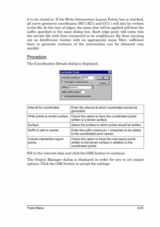
Tools Menu 9-51
it to be stored in. If the Write Intersection Layout Points box is checked, all curve geometry coordinates (BC's EC's and CC's ) will also be written to the file. In the case of edges, the name that will be applied will bear the suffix specified in the main dialog box. Each edge point will come into the terrain file with lines connected to its neighbours. By then carrying out an Intelli-Line routine with an appropriate name filter, sufficient lines to generate contours of the intersection can be obtained very quickly.
Procedure
The Coordination Details dialog is displayed.
Interval for coordinates Enter the interval at which coordinates should be generated.
Write points to terrain surface Check this option to have the coordinated points written to a terrain surface.
Surface Select the surface to which points should be written.
Suffix to add to names Enter the suffix (maximum 1 character) to be added to the coordinated point names
Include intersection layout points
Check this option to have the road layout points written to the terrain surface in addition to the coordinated points.
Fill in the relevant data and click the [OK] button to continue.
The Output Manager dialog is displayed in order for you to set output options. Click the [OK] button to accept the settings.

9-52 Roads Reference
Template Editor
Create new or edit existing road templates
Icon Button Toolbar Shortcut Command
RoadTemplateEditor
This function displays the Road Template Editor dialog that allows the design or editing of templates to be applied to roads. Both single- and dual carriageway templates can be designed.
See the Road Templates section for more details on templates.
Procedure
The Template Editor dialog is displayed. The display will vary according to the number of carriageways.
Single Carriageway Templates

Tools Menu 9-53
New Button
Click this button to clear all current entries. You will be given the option to save the current template if it has been changed.
Load Button
Click this button to load an existing template. You will be given the option to save the current template if it has been changed.
Save As Button
Click this button to save the current template.
Print Button
Click this button in order to generate a listing of the current template details.
Template Type
Select either the Single carriageway or Dual carriageway options. This will define the type of road to which this template can be applied.
Carriageway Width
Enter the width of the carriageways. This setting is used for testing purposes only, the actual crossfalls are set using Edge Levels.
Crossfall (%)
Enter the crossfalls (as a percentage) of the carriageway. This setting is used for testing purposes only, the actual crossfalls are set using Edge Levels.
Allow to Float
Select this option to allow the cut/fill test offsets to float out to the position of greatest difference. The depth used will be the greatest depth difference found between the last compulsory point in the batter section and the points in the base section from the offset of the last compulsory point plus or minus the cut/fill test offset to the base section extremities.
Cut and Fill Offset
Enter the offset from the last compulsory addition (or from the road edge if no compulsory exists) at which the cut/fill state should be checked. The result of this test determines whether the cut or fill template details should be applied. An entry of 0 here is treated as an entry of 0.01m.

9-54 Roads Reference
Dual Carriageway Templates
Template Type
Select either the Single carriageway or Dual carriageway options. This will define the type of road to which this template can be applied.
Pivot point to Shoulder break point
Enter the offset from the Pivot point at which the outer road edge should be located. This offset is applied from the Pivot towards the outside of the section. In conjunction with the Pivot to Median setting this determines the carriageway width. This setting is used for testing purposes only, the actual offsets are set using Edge Levels. This also only applies to dual carriageway templates.
Pivot point to Median break point
Enter the offset from the Pivot point at which the inner road edge should be located. This offset is applied from the Pivot towards the centre of the
Tools Menu 9-55
section. In conjunction with the Pivot to Shoulder setting this determines the carriageway width. This setting is used for testing purposes only, the actual offsets are set using Edge Levels. This also only applies to dual carriageway templates.
Center Line to Pivot point
Enter the offset from the centreline around which the relevant carriageway should pivot. This setting is used for testing purposes only, the actual offsets are set using Edge Levels. This also only applies to dual carriageway templates.
Crossfall (%)
Enter the crossfalls (as a percentage) of the carriageway. This setting is used for testing purposes only, the actual crossfalls are set using Edge Levels.
Allow to Float
Select this option to allow the cut/fill test offsets to float out to the position of greatest difference. The depth used will be the greatest depth difference found between the last compulsory point in the batter section and the points in the base section from the offset of the last compulsory point plus or minus the cut/fill test offset to the base section extremities.
Cut and Fill Offset
Enter the offset from the last compulsory addition (or from the road edge if no compulsory exists) at which the cut/fill state should be checked. The result of this test determines whether the cut or fill template details should be applied. An entry of 0 here is treated as an entry of 0.01m.
9-56 Roads Reference
Compulsory Additions, Batters and Layerworks
These settings are made in the series of tables at the bottom of the Template Editor and are common to both single and dual carriageway roads.
LoMed and UpMed tabs
Enter the horizontal and vertical movements for median details that should be added to the inside edge of the carriageways. The LoMed is applied to the lower of the two median points, while the UpMed details are applied to the upper of these two points. If the median points have the same elevation, then LoMed is applied to the left carriageway and UpMed to the right carriageway. For testing purposes the right carriageway median is artificially raised in order to check the functioning of the entries. This applies to dual carriageway templates only. Also see Special vertical codes.
LComp and RComp tabs
Enter the horizontal and vertical movements for compulsory details that are added to the road shoulder. Each entry (consisting of a horizontal and vertical movement) is applied in succession to the previous point starting from the outside edge of the carriageway. These details are added irrespective of whether the road is in cut or fill. Also see Special vertical codes.
LCut and RCut tabs
Enter the details that should be applied when the road is determined to be in a cut situation at the test position. Enter horizontal and vertical movements that should be applied from the previous point (starting from the last compulsory point or the outside edge of the carriageway if no compulsory exists), the batter slope to be applied from the final point, the minimum and maximum cut heights at which this should be applied, and the minimum offset that should be applied. A special vertical movement code is available.
Multiple (or no) horizontal and vertical movements (a set) are possible with the end of the set being defined by the presence of entries for the batter slope, minimum and maximum heights. Multiple sets are also possible using different minimum and maximum height settings. The maximum height of the final entry in the final set must be set to 999.
The min/max offset entry can be either a maximum, or minimum offset depending on the value of the Offset Type column. This option can be used to force the toe point out to a minimum offset (Min) by flattening

Tools Menu 9-57
the batter slope if necessary, or forcing the toe point to a maximum offset (Max) by increasing the batter slope if necessary.
Special Vertical Movement codes
Entering a value of 888 for a vertical movement will result in a vertical movement calculated from the grade of the previous two points and the entered horizontal movement.
Entering a value of 777 for a vertical movement will result in a vertical movement calculated from the super elevation of the specific section.
LFill and RFill tabs
Enter the details that should be applied when the road is determined to be in a fill situation at the test position. Enter horizontal and vertical movements that should be applied from the previous point (starting from the last compulsory point or the outside edge of the carriageway if no compulsory exists), the batter slope to be applied from the final point, the minimum and maximum cut heights at which this should be applied, and the minimum offset that should be applied. A special vertical movement code is available.
Multiple (or no) horizontal and vertical movements (a set) are possible with the end of the set being defined by the presence of entries for the batter slope, minimum and maximum heights. Multiple sets are also possible using different minimum and maximum height settings. The maximum height of the final entry in the final set must be set to 999.
The min/max offset entry can be either a maximum, or minimum offset depending on the value of the Offset Type column. This option can be used to force the toe point out to a minimum offset (Min) by flattening the batter slope if necessary, or forcing the toe point to a maximum offset (Max) by increasing the batter slope if necessary.
Special Vertical Movement codes
Entering a value of 888 for a vertical movement will result in a vertical movement calculated from the grade of the previous two points and the entered horizontal movement.
Entering a value of 777 for a vertical movement will result in a vertical movement calculated from the super elevation of the specific section.

9-58 Roads Reference
LLayers and RLayers tabs
Enter the details of additional layerworks to be associated with this template. Entries consist of the Left and Right PLC's at which the edges of the layers should be created, optional shifts from the specified PLC's in order to create a stepped layer, the depth of the layer and a description of the layer. See the Road Templates section for more detail on how these layer definitions can be used.
The RLayers tab is only accessible for dual carriageway roads. In this case, if required, the details of the right side layers can be omitted and the left side specification setup to extend across the entire road width.
Right-click on one of these grids and select the TRH 4 Pavements option in order to use a dialog to specify layerworks according to TRH4. Right click on the Pavement Designer option to display the Pavement Designer dialog and specify layerworks according to a user defined Pavement Library.

Tools Menu 9-59
TRH 4 Pavement Layer Designer
In the following dialog the appearance of the large buttons is dependant on the preceding selections. Some combinations of selections have no layer definitions, some have only one (in which case the left button will be visible) and some have two (in which case both buttons will be visible).
Pavement type Select the type of pavement.
Climatic region Select the climatic region. Only applicable to Granular base pavements.
Road category Select the road category.
Traffic class Select the required traffic class.
Calculate class Button Click this button to display the Cumulative E80 Calculator dialog.
Left Button Click this button to select that layer definition which will update the template accordingly.
Right Button Click this button to select that layer definition which will update the template accordingly.

9-60 Roads Reference
Pavement Designer
In this dialog you can create various Pavement libraries containing several manually defined pavement designs. These files can then be used throughout an organization. The pavement symbol, as indicated on the dialog, can be automatically generated on Cross Section plots. The symbols for each material type is specified in a CAD symbol file called PAVEMENT SYMBOLS.DRG in the Symbols sub directory. Standard TRH4 pavement libraries are provided with the program in the “..\Examples\Pavement” Designs sub-directory.
Pavement File Name (...)
Press this to display a File Open dialog. Use this dialog to open an existing Pavement file, or simply type in a new name to create a new Pavement file. A Pavement file can contain several pavement designs.
Pavement All the Pavement designs that are contained in the selected Pavement file will be listed in this combo-box. The selected pavement design will be displayed in the display area.
New Pavement Press this button to add a new pavement design to the selected pavement file. You will be asked for a Pavement Name, which will be listed in the Pavement combo-box. The newly inserted, blank pavement design will automatically be selected. Use the Add Layer option to add layers to the
Delete Pavement Press this button to delete the selected pavement design.
Add Layer Press this button to add a pavement layer to the selected

Tools Menu 9-61
pavement design. The Add Layer will be displayed. The new pavement layer will be added on top of the existing layers.
Edit Layer Press this button to edit the properties of an existing pavement layer. You will be prompted to "Indicate Layer to Edit". Click on the desired layer to display the Edit Layer dialog layer.
Delete Layer Press this button to delete a layer from the selected pavement design. You will be prompted: "Indicate Layer to delete". Click on the desired layer to delete it.
Save As Press this button to save the selected Pavement file to another file.
OK Press OK to save the changes to the selected pavement file. The layers in the selected pavement design will be placed in the LLayers or RLayers tabs of the Template Editor.
Cancel Press Cancel to close the dialog without saving the changes or altering the Template Editor.
Add / Edit Layer Dialog
Descriptor Enter the descriptor that will be printed next to the layer symbol.
Material Select the layer material from the combo-box.
Thickness (m) Enter the layer thickness in meters here.
OK Press OK to Add or Update the layer to the Pavement design.
Cancel Press this button to aboard the Add/Edit process.

9-62 Roads Reference
View Page
Show grid Check this box to have a grid overlaid on the display during redraws.
Vertical exaggeration Use the spin button to specify the exaggeration factor to be applied to elevations during redraws.
Left test and Right test The calculated differences at the test offset are displayed here.
Offset and Elevation The current offset and elevation of the cursor are displayed here.
Add Ground Button Click this button to add a ground definition for testing purposes. Click on positions in the display in order to define the ground points.
Test Button Click this button to check the application of the template on the current ground definition.
Keys Press [R] to redraw, [S] to refresh, [M] to magnify, [D] to demagnify and [W] to pan the display.

Tools Menu 9-63
Template Paths
Associate a number with a template name and path
Icon Button Toolbar Shortcut Command
RoadTemplatePaths
This option is used to establish the link between the disk path and file name of a template file and the template number that is used in the road file as a reference to that particular template.
The Template number has to be entered and the path selected with the browse facility.
Usually a library of templates will be built up in a particular directory. These templates can then be used by any user on any job. For example, the template in 'D:\TEMPLATES\BUS1.TEM' might be called template '2' in roads 1 and 5, but be called template '1' in road 4.
Procedure
The Road Template Paths dialog is displayed.
Template Path Enter the path to and the name of the template file. Click on the […] button to display a file open dialog
Name Enter the template name by which the template will be refer to in all other processing that requires a template.
OK Button Click this button to accept the current entries in the dialog.
Cancel Button Click this button to cancel the function.

9-64 Roads Reference
Right click on the desired row to display a popup menu:
Delete Entry Delete the highlighted entry from the list.
Insert New Insert a blank row into the spreadsheet
Insert Button Click this button to add the current Template Path entries as a new entry in the template list.
Template Editor Click this button to display the Template Editor dialog and load the selected template.
Fill in the relevant data and click the [OK] button to continue.

Tools Menu 9-65
Chainage Equation
Enter long/short chainages for the road
Icon Button Toolbar Shortcut Command
RoadChainageEquation
This function allows you to add or subtract a constant from a certain chainage run to accommodate long or short chainages.
A start chainage, stop chainage and a constant to apply on that stretch must be specified. The result will be that all vertical and horizontal alignments, as well as the resultant volume calculations, will take into account the long or short chain at the start and/or end of the specified stretch.
Within the stretch itself, generated points will be called by the chainage name but be coordinated at the correct position.
The constant is applied to all chainages greater than the start chainage but less than or equal to the stop chainage.
Procedure
The Chainage Equation dialog is displayed.
Delete Button Click on an entry in the equation list and then click this button to delete the highlighted entry from the list.

9-66 Roads Reference
Equation - Start Enter the chainage beyond which the chainage equation comes into effect. This chainage is not included in the effective range.
Equation - Stop Enter the chainage at which the chainage equation ceases to have an effect. This chainage is included in the effective range.
Equation - Chainage constant Enter the constant to be added on to all chainages in the effective range.
Insert Button Click this button to add the current equation entries to the equation list.
Update Button Click this button to update the highlighted entry in the equation list with the current equation entries.
Fill in the relevant details and then click the [OK] button to continue.

Index
A Add Template ................................................................................................... 7-14 Angular Measure................................................................................................ 2-2 Apply Template .................................................................................................. 7-4 Area Indicator.................................................................................. 7-6, 7-26, 9-17 Area optimisation....................................................................................7-17, 7-20 Areas.............................................................. 7-4, 7-8, 7-11, 7-17, 7-20, 7-23, 7-24 Automatic Optimize......................................................................................... 7-17
B Basic Theory ....................................................................................................... 2-1 Batter Slope Adjustment................................................................................ 9-18 Batter Slope Extraction.................................................................................. 9-17 Batters...................................................................7-6, 7-23, 9-17, 9-18, 9-26, 9-33 Bellmouth .......................................................................................................... 9-39 Berms ................................................................................................................. 7-14 Bulking/Compaction ..............................................................................7-27, 7-29
C Cards................................................................................................................... 4-15 Chainage .............................................................................................................. 2-2 Chainage Equation .......................................................................................... 9-65 Chainage record batch delete ................................................................................................... 9-21 delete............................................................................................................... 9-20 edit..................................................................................................................... 9-6 insert ......................................................................................................9-22, 9-23 list ...................................................................................................................... 9-5 set fields............................................................................................................ 9-7 switch on/off .................................................................................................... 9-9
Chainages ............................................................................................................ 2-2 Civil Designer ..................................................................................................... 2-1 Comma-delimited ............................................................................................ 4-12 Comparative Levels......................................................................................... 9-36 Connect Extremities........................................................................................ 7-13 Conventions ........................................................................................................ 2-2 Coordinate......................................................................................................... 9-50 Coordinate System ............................................................................................ 2-2 Cross Check....................................................................................................... 9-33 Cross section add or subtract constants ........................................................................... 5-24
delete point ......................................................................................................5-6 edit ...................................................................................................................5-13 edit point ..........................................................................................................5-5 enter ................................................................................................................5-13 expand or shrink...........................................................................................5-27 go to .................................................................................................................5-10 graphical edit...................................................................................................5-2 insert point.......................................................................................................5-4 interpolate elevation ....................................................................................5-15 layer deduction..............................................................................................5-36 layer display...................................................................................................5-11 layerworks......................................................................................................5-32 list.....................................................................................................................5-12 move point........................................................................................................5-7 remove points ................................................................................................5-18 transfer points ...............................................................................................5-21 width................................................................................................................5-27
Crossfall..............................................................................................................6-36 Cumulative Volumes........................................................................................7-29 Curve...................................................................................................................9-47 Cut slope.............................................................................................................9-56
D Dam Areas .........................................................................................................7-11 Datum ...................................................................................................................2-2 Daylighting ........................................................................................................9-18 Delete Chainage................................................................................................9-20 Design criteria...................................................................................................6-55 Dual Carriageway................................................................................... 6-24, 9-54 Dump Area...........................................................................................................7-8
E Edge Control .....................................................................................................6-36 Edge Levels .......................................................................................................6-36 Edit Curves ........................................................................................................9-47 Edit Super..........................................................................................................6-36 Edit super-elevation.........................................................................................6-36 Export cross sections.................................................................................................4-23 long section ....................................................................................................4-24
F File Menu .............................................................................................................4-1 Fill slope .............................................................................................................9-57 Full Level Table................................................................................................9-34

H Horizontal Alignment ....................................................................................... 6-2 calculate ......................................................................................................... 6-11 coordinate ...................................................................................................... 6-11 curve fit ............................................................................................................ 6-8 delete HPI........................................................................................................ 6-5 edit..................................................................................................................... 6-3 edit HPI ............................................................................................................ 6-6 insert HPI ........................................................................................................ 6-4 join data.......................................................................................................... 6-13 list .................................................................................................................... 6-10 move HPI ......................................................................................................... 6-7 offset centreline ............................................................................................ 6-14 setting out ...................................................................................................... 6-13
HPI........................................................................................................................ 6-2
I Import ASCII files...................................................................................................... 4-12 Cards cross sections..................................................................................... 4-15 cross sections ................................................................................................ 4-12 long sections.................................................................................................. 4-18 Stardust roads file ...............................................................................4-20, 4-22
Index............................................................................................................7-26, 9-2 chainage record .............................................................................................. 9-2 layer record ..................................................................................................... 9-3
Insert chainage................................................................................................. 9-22 intersection edit................................................................................................................... 9-45
Intersection ....................................................................................................... 9-39 bellmouth....................................................................................................... 9-39 calculate levels .............................................................................................. 9-49 coordinate ...................................................................................................... 9-50 edit curves...................................................................................................... 9-47 layout .............................................................................................................. 9-48 load an existing............................................................................................. 9-44 save an existing............................................................................................. 9-45 taper ................................................................................................................ 9-39
Irregular chain.................................................................................................. 9-22
K K Value............................................................................................................... 6-34 Kerb .................................................................................................................... 9-56

L Latitude ................................................................................................................2-2 Layer Deduction...............................................................................................5-36 Layer Design .....................................................................................................9-59 Layer names ......................................................................................................4-10 Layer record edit ...................................................................................................................9-11 list.....................................................................................................................9-10 set fields ..........................................................................................................9-13 transfer fields.................................................................................................9-15
Layerwork Box .................................................................................................5-32 Layerwork Volumes.........................................................................................7-31 Layerworks..................................................................5-32, 5-39, 7-31, 9-58, 9-59 Levels...............................................................................................9-33, 9-34, 9-36 Line Intersection ................................................................................................5-9 Lines......................................................................................................................2-2 LO..........................................................................................................................2-2 Long and short chains.....................................................................................9-65 Longitude.............................................................................................................2-2
M Manual Optimize .................................................................................... 7-20, 7-22 Masshaul ............................................................................................................7-27 Masshaul Volume .............................................................................................7-27 Mean Sea Level ..................................................................................................2-2
N Northern Hemisphere .......................................................................................2-2
O Offset centreline ...............................................................................................6-14 Offset Poles ........................................................................................................9-28 Option settings..................................................................................................4-30 Output.................................................................................................................4-27
P Perimeter .............................................................................................................5-8 Pipe auto lengths....................................................................................................8-12 auto manholes ...............................................................................................8-10 delete .................................................................................................................8-4 display ground lines .......................................................................................8-8 edit ............................................................................................................. 8-2, 8-5 insert .................................................................................................................8-3 invert levels............................................................................................ 8-9, 8-18 long section ...................................................................................8-8, 8-10, 8-12

manhole data................................................................................................. 8-16 move.................................................................................................................. 8-7 parallel to ground......................................................................................... 8-14 review alignment............................................................................................ 8-9 trench volumes ............................................................................................. 8-19
Pipeline ................................................................................................................ 2-1 Polygon Area....................................................................................................... 5-8 Profile/Batters .................................................................................................. 9-26 Project new.................................................................................................................... 4-2 open................................................................................................................... 4-7 save.................................................................................................................... 4-9
R Recalculate ...............................................................................................7-23, 7-24 Rehabilitation ................................................................................................... 6-49 Relative Poles ................................................................................................... 9-30 Road...................................................................................................................... 2-1 Road Expert ...................................................................................................... 6-54 Road Reserves .................................................................................................. 7-22
S Sections.........................................................................................................2-1, 2-2 Select Road File ............................................................................................... 4-10 Set Batters........................................................................................................... 7-6 Setting Out ........................................................................................................ 6-13 Sidewalk ............................................................................................................ 9-56 Sight Distance................................................................................................... 6-68 Single Carriageway ......................................................................................... 9-52 Solidify Layerworks ........................................................................................ 5-39 Southern Hemisphere....................................................................................... 2-2 Spool ................................................................................................................... 4-29 Super broken back curves...................................................................................... 6-66 compound curves ......................................................................................... 6-67 delete............................................................................................................... 6-39 display setup.................................................................................................. 6-43 edit..........................................................................................................6-36, 6-40 expert.............................................................................................................. 6-44 graph............................................................................................................... 6-63 insert ............................................................................................................... 6-38 levels ............................................................................................................... 6-48 move................................................................................................................ 6-42 reverse curves ............................................................................................... 6-65 runoff .............................................................................................................. 6-62 single curve.................................................................................................... 6-64

Super-elevation.................................................................................................6-36 Super-Elevation................................................................................................6-60
T Taper...................................................................................................................9-39 Template ...........................................................................................7-4, 7-14, 9-52 files...................................................................................................................9-63 paths ................................................................................................................9-63
Template layerworks......................................................................................................9-59
Template Editor................................................................................................9-52 Trench Volumes ...............................................................................................8-19 TRH 4..................................................................................................................9-59 TRH design standards.....................................................................................6-55
U Use Index ...........................................................................................................7-26
V Vertical Alignment curve fit ...........................................................................................................6-35 delete VPI.......................................................................................................6-26 display ground lines .....................................................................................6-29 edit ...................................................................................................................6-21 edit VPI ...........................................................................................................6-27 insert VPI .......................................................................................................6-25 introduction ...................................................................................................6-20 levels................................................................................................................6-32 list.....................................................................................................................6-31 move VPI ........................................................................................................6-28
Vertical levels ....................................................................................................6-32