Embed Size (px)
Citation preview
Journal of Structural Geology 28 (2006) 1658e1669www.elsevier.com/locate/jsg
Riedel-shear control on the development of pennant veins:Field example and analogue modelling
Sara Coelho a,*, Cees Passchier a, Fernando Marques b
a Department of Earth Sciences, University of Mainz, Becherweg 21, 55099 Mainz, Germanyb Department of Geology and CGUL, University of Lisbon, Lisbon, Portugal
Received 1 December 2005; received in revised form 17 May 2006; accepted 29 May 2006
Available online 26 July 2006
Abstract
The wall rocks of a crustal scale sinistral ductile shear zone in Namibia, the Purros Mylonite Zone, contain two types of asymmetric quartzveins. Bedding surfaces contain sigmoidal quartz veins with limited thickness along their symmetry axes that can be classified as tension gashes.A second type of veins consists of a striated central fault vein separating pennant-type quartz filled terminations. The tips of these ‘‘pennantveins’’ have a different orientation to those of the tension gashes. Analogue experiments were carried out using a sheet of silicone powder sus-pended on a slab of poly-dimethyl-siloxane (PDMS), both deformed in simple shear. These experiments produced open fractures very similar tothe pennant veins that form by intersection of R and R0 Riedel shear fractures. These fractures rotate and slip during progressive deformation,opening pennant shaped gaps. We interpret the natural pennant veins to form by the same mechanism of R and R0 shear fracture initiation, andsubsequent rotation and opening. Since this mechanism differs from that of previously described vein types such as wing cracks, tension gashesand swordtail or fishmouth termination veins, which mainly open as tension veins, we consider pennant veins as in new independent class ofasymmetric mineral-filled veins.� 2006 Elsevier Ltd. All rights reserved.
1. Introduction
Veins are extension fractures filled with mineral deposits,commonly quartz or calcite, and one of the most common fea-tures in deformed rocks of all types and metamorphic grades.Opening of veins is structurally controlled by orientation offractures in a volume of rock but other parameters, like porefluid pressure or porosity, are also important. Single or enechelon tension gashes (Fig. 1a; e.g. Ramsay and Huber,1983; Olson and Pollard, 1991), wing cracks (e.g. Horii andNemat-Nasser, 1985; Willemse and Pollard, 1998) and sword-tail terminations in boudin parting surfaces (Swanson, 1992)are common examples of veins developed as mode I extensionfractures. As such, they can be used in the interpretation ofbulk flow kinematics and are an important source of informa-tion on the deformation history of the host-rock, especially if
* Corresponding author.
E-mail address: [email protected] (S. Coelho).
0191-8141/$ - see front matter � 2006 Elsevier Ltd. All rights reserved.
doi:10.1016/j.jsg.2006.05.009
associated with fibres (e.g. Bons, 2000; Kohn et al., 2000;Hilgers and Urai, 2002). However, pure tension fractures arenot the only structural control on the development of veins.This paper explores an alternative way of opening space formineral deposition controlled by Riedel (R) and anti-Riedel(R0) conjugate shear fractures.
Riedel shear fractures were first recognised as a principalfeature of brittle to semi-brittle shear zones by Riedel(1929), who produced these structures in analogue experi-ments with clay. The subject has since been the focus of exten-sive research in field studies (e.g. Moore, 1979; Davis et al.,1999; Ahlgren, 2001; Katz et al., 2004), analogue modellingwith clay (e.g. Cloos, 1955; Wilcox et al., 1973; Tchalenko,1968; Smith and Durney, 1992; Marques, 2001) and sand(e.g. Naylor et al., 1986), direct shear experiments (e.g. Bar-tlett et al., 1981; Moore and Byerlee, 1992; Schreus, 1994)and numerical modelling (e.g. Dresen, 1991; Braun, 1994;McKinnon and Garrido de la Barra, 1998). These works re-sulted in a widely accepted model of shear fracture orientationin non-coaxial deformation, illustrated in Fig. 1b. The most

1659S. Coelho et al. / Journal of Structural Geology 28 (2006) 1658e1669
conspicuous element of this idealised geometry is the Riedelconjugate set, comprising synthetic Riedel fractures (R) andconjugate antithetical Riedel fractures (R0), oriented at45� � f/2, where f is the internal angle of friction of therock. Also important are synthetical P-shear fractures (at�45� þ f/2) and the purely tensional T fractures (at 45� insimple shear). The precise angular relationships of the differ-ent sets of fractures and the shear plane are dependent on the
Fig. 1. (a) Geometry of an idealised tension gash in sinistral simple shear. ISA,
instantaneous stretching axes; (b) theoretical distribution of tensional fractures
(T ) and shear fractures (R, R0 and P) in the same kinematical framework.
ff, internal friction angle.
internal angle of friction, as well as on the strain rate and stressstate (Ahlgren, 2001) and vorticity (Smith and Durney, 1992).This framework is generally interpreted as a precursor to faultsin a synthetically driven model (e.g. Ahlgren, 2001) whereR fractures are the first to develop, followed by P fractures.This paper investigates the influence of ReR0 conjugate frac-tures as structural controls on veins, following the work ofSwanson (1992), who suggested that R fractures had somerole in the kinematics of vein terminations. This paper also in-troduces pennant veins, a new type of vein geometry, based onfield observations in Namibia and analogue modelling.
2. Geological setting
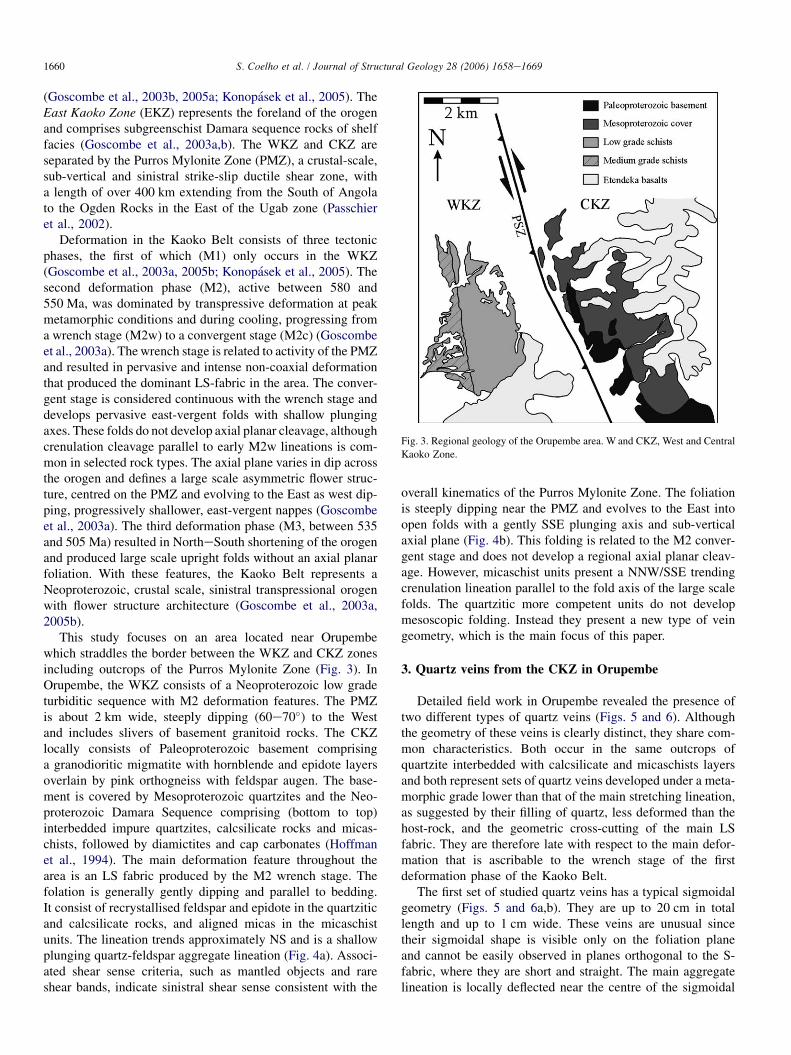
The Kaoko Belt in Namibia is a NNW trending, obliqueconvergent orogen, divided into three zones (Goscombeet al., 2003a, 2005a,b; Konopasek et al., 2005; Fig. 2). TheWest Kaoko Zone (WKZ) includes basement composed ofPanafrican migmatites and granites with amphibolite to gran-ulite metamorphic facies (Goscombe et al., 2003b, 2005a).The Central Kaoko Zone (CKZ) comprises a Paleoproterozoicbasement of migmatitic and gneissic rocks with a Neoprotero-zoic cover of deep basin and slope facies (Damara sequence;Goscombe et al., 2003a; Konopasek et al., 2005). Metamor-phic conditions on the CKZ grade from upper-amphibolitefacies in the West to lower greenschist facies in the East
Fig. 2. Regional geology of the Kaoko Belt; studied area shown by a square. Inset: location of the Kaoko Belt with respect to the major cratons and mobile belts in
Southern Africa. WKZ, CKZ and EKZ: Western, Central and Eastern Kaoko Zones. ST, Sesfontein thrust. PMZ, Purros Mylonite Zone. Simplified from Goscombe
et al. (2003a, Fig. 1).
1660 S. Coelho et al. / Journal of Structural Geology 28 (2006) 1658e1669
(Goscombe et al., 2003b, 2005a; Konopasek et al., 2005). TheEast Kaoko Zone (EKZ) represents the foreland of the orogenand comprises subgreenschist Damara sequence rocks of shelffacies (Goscombe et al., 2003a,b). The WKZ and CKZ areseparated by the Purros Mylonite Zone (PMZ), a crustal-scale,sub-vertical and sinistral strike-slip ductile shear zone, witha length of over 400 km extending from the South of Angolato the Ogden Rocks in the East of the Ugab zone (Passchieret al., 2002).
Deformation in the Kaoko Belt consists of three tectonicphases, the first of which (M1) only occurs in the WKZ(Goscombe et al., 2003a, 2005b; Konopasek et al., 2005). Thesecond deformation phase (M2), active between 580 and550 Ma, was dominated by transpressive deformation at peakmetamorphic conditions and during cooling, progressing froma wrench stage (M2w) to a convergent stage (M2c) (Goscombeet al., 2003a). The wrench stage is related to activity of the PMZand resulted in pervasive and intense non-coaxial deformationthat produced the dominant LS-fabric in the area. The conver-gent stage is considered continuous with the wrench stage anddevelops pervasive east-vergent folds with shallow plungingaxes. These folds do not develop axial planar cleavage, althoughcrenulation cleavage parallel to early M2w lineations is com-mon in selected rock types. The axial plane varies in dip acrossthe orogen and defines a large scale asymmetric flower struc-ture, centred on the PMZ and evolving to the East as west dip-ping, progressively shallower, east-vergent nappes (Goscombeet al., 2003a). The third deformation phase (M3, between 535and 505 Ma) resulted in NortheSouth shortening of the orogenand produced large scale upright folds without an axial planarfoliation. With these features, the Kaoko Belt represents aNeoproterozoic, crustal scale, sinistral transpressional orogenwith flower structure architecture (Goscombe et al., 2003a,2005b).
This study focuses on an area located near Orupembewhich straddles the border between the WKZ and CKZ zonesincluding outcrops of the Purros Mylonite Zone (Fig. 3). InOrupembe, the WKZ consists of a Neoproterozoic low gradeturbiditic sequence with M2 deformation features. The PMZis about 2 km wide, steeply dipping (60e70�) to the Westand includes slivers of basement granitoid rocks. The CKZlocally consists of Paleoproterozoic basement comprisinga granodioritic migmatite with hornblende and epidote layersoverlain by pink orthogneiss with feldspar augen. The base-ment is covered by Mesoproterozoic quartzites and the Neo-proterozoic Damara Sequence comprising (bottom to top)interbedded impure quartzites, calcsilicate rocks and micas-chists, followed by diamictites and cap carbonates (Hoffmanet al., 1994). The main deformation feature throughout thearea is an LS fabric produced by the M2 wrench stage. Thefolation is generally gently dipping and parallel to bedding.It consist of recrystallised feldspar and epidote in the quartziticand calcsilicate rocks, and aligned micas in the micaschistunits. The lineation trends approximately NS and is a shallowplunging quartz-feldspar aggregate lineation (Fig. 4a). Associ-ated shear sense criteria, such as mantled objects and rareshear bands, indicate sinistral shear sense consistent with the
overall kinematics of the Purros Mylonite Zone. The foliationis steeply dipping near the PMZ and evolves to the East intoopen folds with a gently SSE plunging axis and sub-verticalaxial plane (Fig. 4b). This folding is related to the M2 conver-gent stage and does not develop a regional axial planar cleav-age. However, micaschist units present a NNW/SSE trendingcrenulation lineation parallel to the fold axis of the large scalefolds. The quartzitic more competent units do not developmesoscopic folding. Instead they present a new type of veingeometry, which is the main focus of this paper.
3. Quartz veins from the CKZ in Orupembe
Detailed field work in Orupembe revealed the presence oftwo different types of quartz veins (Figs. 5 and 6). Althoughthe geometry of these veins is clearly distinct, they share com-mon characteristics. Both occur in the same outcrops ofquartzite interbedded with calcsilicate and micaschists layersand both represent sets of quartz veins developed under a meta-morphic grade lower than that of the main stretching lineation,as suggested by their filling of quartz, less deformed than thehost-rock, and the geometric cross-cutting of the main LSfabric. They are therefore late with respect to the main defor-mation that is ascribable to the wrench stage of the firstdeformation phase of the Kaoko Belt.
The first set of studied quartz veins has a typical sigmoidalgeometry (Figs. 5 and 6a,b). They are up to 20 cm in totallength and up to 1 cm wide. These veins are unusual sincetheir sigmoidal shape is visible only on the foliation planeand cannot be easily observed in planes orthogonal to the S-fabric, where they are short and straight. The main aggregatelineation is locally deflected near the centre of the sigmoidal
Fig. 3. Regional geology of the Orupembe area. W and CKZ, West and Central
Kaoko Zone.
1661S. Coelho et al. / Journal of Structural Geology 28 (2006) 1658e1669
Fig. 4. Stereoplots representing field data for (a) stretching lineations and (b) foliations of the Orupembe area. N, number of measurements.
veins. The tips and centres of these sigmoidal veins were mea-sured as lines within the foliation plane, as summarised inTable 1. Tips define an average 77� angle with the lineation,whilst the centres are relatively less inclined with an averageangle of 34�. In some examples, a younger vein generationcuts the central part of the veins with the same orientationas the tips (Fig. 6a). The veins are interpreted as sigmoidal ten-sion gashes, developed by progressive deformation of a quartz-filled tensional fracture oriented according to the maximumshortening instantaneous stretching axis (ISA) (cf. Fig. 1a;Ramsay and Huber, 1983; Passchier and Trouw, 2005).
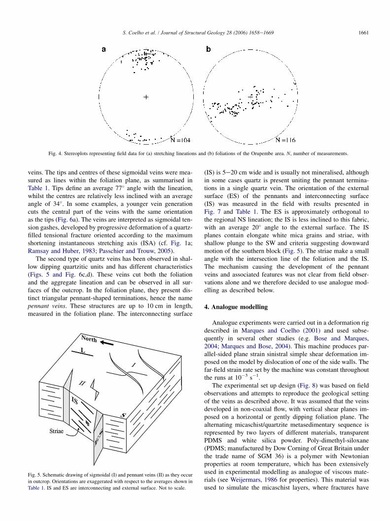
The second type of quartz veins has been observed in shal-low dipping quartzitic units and has different characteristics(Figs. 5 and Fig. 6c,d). These veins cut both the foliationand the aggregate lineation and can be observed in all sur-faces of the outcrop. In the foliation plane, they present dis-tinct triangular pennant-shaped terminations, hence the namepennant veins. These structures are up to 10 cm in length,measured in the foliation plane. The interconnecting surface
Fig. 5. Schematic drawing of sigmoidal (I) and pennant veins (II) as they occur
in outcrop. Orientations are exaggerated with respect to the averages shown in
Table 1. IS and ES are interconnecting and external surface. Not to scale.
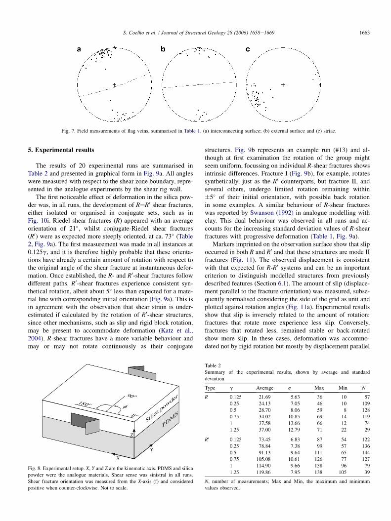
(IS) is 5e20 cm wide and is usually not mineralised, althoughin some cases quartz is present uniting the pennant termina-tions in a single quartz vein. The orientation of the externalsurface (ES) of the pennants and interconnecting surface(IS) was measured in the field with results presented inFig. 7 and Table 1. The ES is approximately orthogonal tothe regional NS lineation; the IS is less inclined to this fabric,with an average 20� angle to the external surface. The ISplanes contain elongate white mica grains and striae, withshallow plunge to the SW and criteria suggesting downwardmotion of the southern block (Fig. 5). The striae make a smallangle with the intersection line of the foliation and the IS.The mechanism causing the development of the pennantveins and associated features was not clear from field obser-vations alone and we therefore decided to use analogue mod-elling as described below.
4. Analogue modelling
Analogue experiments were carried out in a deformation rigdescribed in Marques and Coelho (2001) and used subse-quently in several other studies (e.g. Bose and Marques,2004; Marques and Bose, 2004). This machine produces par-allel-sided plane strain sinistral simple shear deformation im-posed on the model by dislocation of one of the side walls. Thefar-field strain rate set by the machine was constant throughoutthe runs at 10�3 s�1.
The experimental set up design (Fig. 8) was based on fieldobservations and attempts to reproduce the geological settingof the veins as described above. It was assumed that the veinsdeveloped in non-coaxial flow, with vertical shear planes im-posed on a horizontal or gently dipping foliation plane. Thealternating micaschist/quartzite metasedimentary sequence isrepresented by two layers of different materials, transparentPDMS and white silica powder. Poly-dimethyl-siloxane(PDMS; manufactured by Dow Corning of Great Britain underthe trade name of SGM 36) is a polymer with Newtonianproperties at room temperature, which has been extensivelyused in experimental modelling as analogue of viscous mate-rials (see Weijermars, 1986 for properties). This material wasused to simulate the micaschist layers, where fractures have

1662 S. Coelho et al. / Journal of Structural Geology 28 (2006) 1658e1669
Fig. 6. Field examples of sigmoidal tension gashes (a,b) and pennant termination veins (c,d). T, tensional fracture (cf. Fig. 1); IS and ES, interconnecting and
external surfaces. All photos parallel to foliation plane.
not been observed, and was in complete adherence with therig’s side walls. On top of the PDMS (Fig. 8), a layer offine-grained (20 mm) silica powder was placed to representthe quartzite units. This material has cohesion of 300 Pa andfails according to a Coulomb criterion (Krantz, 1991). Similarpowdered silica has been used as an analogue for the brittleupper crust in experiments by Galland et al. (2003). The silicapowder layer was built by sieving with the help of a sugarsprinkler cooking device, from a height of about 10 cm. Byusing the same handling technique, physical properties ofthe silica powder such as density, cohesion and internal angleof friction are assured to remain similar in all runs (Krantz,1991). The observation surface was imprinted with a grid ofmarkers in five of the experimental runs. These markers
Table 1
Summary of field measurements on the two sets of veins
Tips Centres
Sigmoidal veins
(lines to L)
Av s N Av s N
77 20.2 96 34 16.5 52
Pennant veins
(poles to planes)
Av ES N Av IS N Av Str N
175/90 34 161/85 82 247/17 54
Av, average; ES/IS, external/internal surface; Str, striae; N, number of
measurements.
provided a gauge for dislocation (or slip) in the developingR/R0 systems.
The boundary conditions imposed by the setup of the ex-periments specify that deformation is transmitted, point bypoint, to the silica powder from the PDMS underneath, notby push from the confining walls. The silica powder is uncon-fined in the vertical direction. The setup further determinesthat the simple shear plane is orthogonal to bedding, whichis in good agreement with the fact that the field examples oc-cur on the foliation plane.
The evolution of fracture orientation with progressive de-formation is described by the angle f, measured between thefracture and the X-axis of finite strain (Fig. 8). Counter clock-wise angles were considered positive; this corresponds to syn-thetic rotation of the fractures in the given sinistral shearsense. For every run the orientation of fracture sets was mea-sured at shear strain gamma values of 0.125, 0.25, 0.5, 0.75and 1.0g. Although the rig is capable of attaining higher shearstrains (up to 12g), the experiments were limited to a maxi-mum of 1.25g. After this amount of shear strain, the observa-tion surface was disrupted in such a way that it was virtuallyimpossible to follow the evolution of individual sets of frac-tures any further. This is also the reason why the number ofmeasurements in the latest stages of the experiments is lessthan for the initial part (Table 2): in numerous examples, theindividual shear fractures were lost in the disrupted surfaceafter a certain amount of deformation.
1663S. Coelho et al. / Journal of Structural Geology 28 (2006) 1658e1669
Fig. 7. Field measurements of flag veins, summarised in Table 1. (a) interconnecting surface; (b) external surface and (c) striae.
5. Experimental results
The results of 20 experimental runs are summarised inTable 2 and presented in graphical form in Fig. 9a. All angleswere measured with respect to the shear zone boundary, repre-sented in the analogue experiments by the shear rig wall.
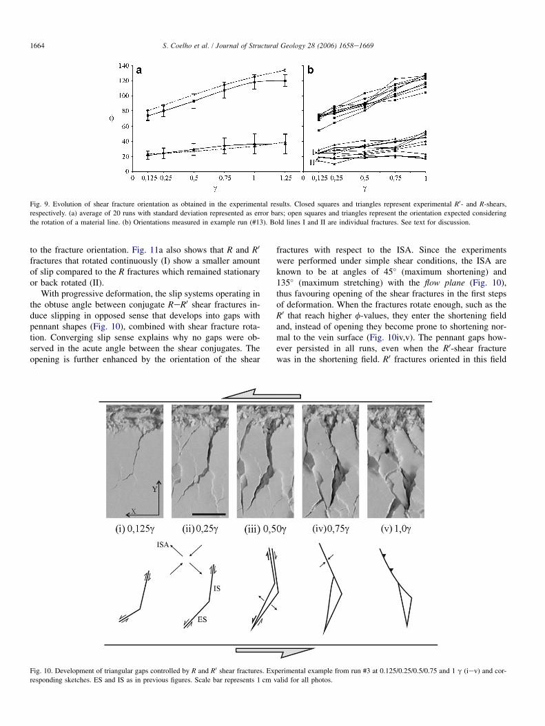
The first noticeable effect of deformation in the silica pow-der was, in all runs, the development of ReR0 shear fractures,either isolated or organised in conjugate sets, such as inFig. 10i. Riedel shear fractures (R) appeared with an averageorientation of 21�, whilst conjugate-Riedel shear fractures(R0) were as expected more steeply oriented, at ca. 73� (Table2, Fig. 9a). The first measurement was made in all instances at0.125g, and it is therefore highly probable that these orienta-tions have already a certain amount of rotation with respect tothe original angle of the shear fracture at instantaneous defor-mation. Once established, the R- and R0-shear fractures followdifferent paths. R0-shear fractures experience consistent syn-thetical rotation, albeit about 5� less than expected for a mate-rial line with corresponding initial orientation (Fig. 9a). This isin agreement with the observation that shear strain is under-estimated if calculated by the rotation of R0-shear structures,since other mechanisms, such as slip and rigid block rotation,may be present to accommodate deformation (Katz et al.,2004). R-shear fractures have a more variable behaviour andmay or may not rotate continuously as their conjugate
Fig. 8. Experimental setup. X, Y and Z are the kinematic axis. PDMS and silica
powder were the analogue materials. Shear sense was sinistral in all runs.
Shear fracture orientation was measured from the X-axis (f) and considered
positive when counter-clockwise. Not to scale.
structures. Fig. 9b represents an example run (#13) and al-though at first examination the rotation of the group mightseem uniform, focussing on individual R-shear fractures showsintrinsic differences. Fracture I (Fig. 9b), for example, rotatessynthetically, just as the R0 counterparts, but fracture II, andseveral others, undergo limited rotation remaining within�5� of their initial orientation, with possible back rotationin some examples. A similar behaviour of R-shear fractureswas reported by Swanson (1992) in analogue modelling withclay. This dual behaviour was observed in all runs and ac-counts for the increasing standard deviation values of R-shearfractures with progressive deformation (Table 1, Fig. 9a).
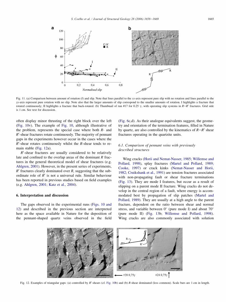
Markers imprinted on the observation surface show that slipoccurred in both R and R0 and that these structures are mode IIfractures (Fig. 11). The observed displacement is consistentwith that expected for R-R0 systems and can be an importantcriterion to distinguish modelled structures from previouslydescribed features (Section 6.1). The amount of slip (displace-ment parallel to the fracture orientation) was measured, subse-quently normalised considering the side of the grid as unit andplotted against rotation angles (Fig. 11a). Experimental resultsshow that slip is inversely related to the amount of rotation:fractures that rotate more experience less slip. Conversely,fractures that rotated less, remained stable or back-rotatedshow more slip. In these cases, deformation was accommo-dated not by rigid rotation but mostly by displacement parallel
Table 2
Summary of the experimental results, shown by average and standard
deviation
Type g Average s Max Min N
R 0.125 21.69 5.63 36 10 57
0.25 24.13 7.05 46 10 109
0.5 28.70 8.06 59 8 128
0.75 34.02 10.85 69 14 119
1 37.58 13.66 66 12 74
1.25 37.00 12.79 71 22 29
R0 0.125 73.45 6.83 87 54 122
0.25 78.84 7.38 99 57 136
0.5 91.13 9.64 111 65 144
0.75 105.08 10.61 126 77 127
1 114.90 9.66 138 96 79
1.25 119.86 7.95 138 105 39
N, number of measurements; Max and Min, the maximum and minimum
values observed.
1664 S. Coelho et al. / Journal of Structural Geology 28 (2006) 1658e1669
Fig. 9. Evolution of shear fracture orientation as obtained in the experimental results. Closed squares and triangles represent experimental R0- and R-shears,
respectively. (a) average of 20 runs with standard deviation represented as error bars; open squares and triangles represent the orientation expected considering
the rotation of a material line. (b) Orientations measured in example run (#13). Bold lines I and II are individual fractures. See text for discussion.
to the fracture orientation. Fig. 11a also shows that R and R0
fractures that rotated continuously (I) show a smaller amountof slip compared to the R fractures which remained stationaryor back rotated (II).
With progressive deformation, the slip systems operating inthe obtuse angle between conjugate ReR0 shear fractures in-duce slipping in opposed sense that develops into gaps withpennant shapes (Fig. 10), combined with shear fracture rota-tion. Converging slip sense explains why no gaps were ob-served in the acute angle between the shear conjugates. Theopening is further enhanced by the orientation of the shear
fractures with respect to the ISA. Since the experimentswere performed under simple shear conditions, the ISA areknown to be at angles of 45� (maximum shortening) and135� (maximum stretching) with the flow plane (Fig. 10),thus favouring opening of the shear fractures in the first stepsof deformation. When the fractures rotate enough, such as theR0 that reach higher f-values, they enter the shortening fieldand, instead of opening they become prone to shortening nor-mal to the vein surface (Fig. 10iv,v). The pennant gaps how-ever persisted in all runs, even when the R0-shear fracturewas in the shortening field. R0 fractures oriented in this field
Fig. 10. Development of triangular gaps controlled by R and R0 shear fractures. Experimental example from run #3 at 0.125/0.25/0.5/0.75 and 1 g (iev) and cor-
responding sketches. ES and IS as in previous figures. Scale bar represents 1 cm valid for all photos.
1665S. Coelho et al. / Journal of Structural Geology 28 (2006) 1658e1669
Fig. 11. (a) Comparison between amount of rotation (f) and slip. Note that lines parallel to the xx-axis represent pure slip with no rotation and lines parallel to the
yy-axis represent pure rotation with no slip. Note also that the larger amounts of slip correspond to the smaller amounts of rotation. I highlights a fracture that
rotated continuously; II highlights a fracture that back-rotated. (b) Thumbnail of run #17 for 0.25 g, with operating slip systems in ReR0 fractures. Grid side
is 1 cm. See text for discussion.
often display minor thrusting of the right block over the left(Fig. 10v). The example of Fig. 10, although illustrative ofthe problem, represents the special case where both R- andR0-shear fractures rotate continuously. The majority of pennantgaps in the experiments however occur in the cases where theR0-shear rotates continuously whilst the R-shear tends to re-main stable (Fig. 12a).
R0-shear fractures are usually considered to be relativelylate and confined to the overlap areas of the dominant R frac-tures in the general theoretical model of shear fractures (e.g.Ahlgren, 2001). However, in the present series of experiments,R0 fractures clearly dominated over R, suggesting that the sub-ordinate role of R0 is not a universal rule. Similar behaviourhas been reported in previous studies based on field examples(e.g. Ahlgren, 2001; Katz et al., 2004).
6. Interpretation and discussion
The gaps observed in the experimental runs (Figs. 10 and12) and described in the previous section are interpretedhere as the space available in Nature for the deposition ofthe pennant-shaped quartz veins observed in the field
(Fig. 6c,d). As their analogue equivalents suggest, the geome-try and orientation of the termination features, filled in Natureby quartz, are also controlled by the kinematics of ReR0 shearfractures operating in the quartzite units.
6.1. Comparison of pennant veins with previouslydescribed structures
Wing cracks (Horii and Nemat-Nasser, 1985; Willemse andPollard, 1998), splay fractures (Martel and Pollard, 1989;Cooke, 1997) or crack kinks (Nemat-Nasser and Horii,1982; Cruikshank et al., 1991) are tension fractures associatedwith non-propagating fault or shear fracture terminations(Fig. 13). They are mode I features, but occur as a result ofslipping on a parent mode II fracture. Wing cracks do not de-velop in the central region of a fault, where energy is accom-modated best by propagation of slip patches (Martel andPollard, 1989). They are usually at a high angle to the parentfracture, dependent on the ratio between shear and normalstress, and variable between 0� (pure mode I) and about 70�
(pure mode II) (Fig. 13b; Willemse and Pollard, 1998).Wing cracks are also commonly associated with solution
Fig. 12. Examples of triangular gaps: (a) controlled by R0-shears (cf. Fig. 10b) and (b) R-shear dominated (less common). Scale bars are 1 cm in length.
1666 S. Coelho et al. / Journal of Structural Geology 28 (2006) 1658e1669
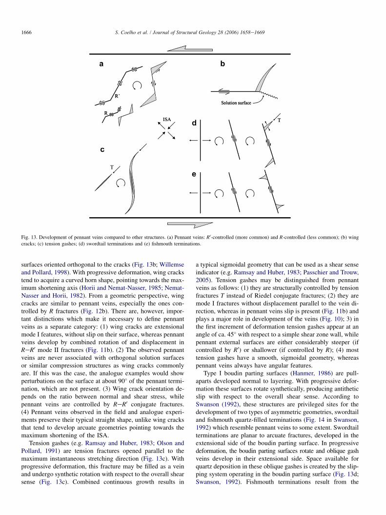
Fig. 13. Development of pennant veins compared to other structures. (a) Pennant veins: R0-controlled (more common) and R-controlled (less common); (b) wing
cracks; (c) tension gashes; (d) swordtail terminations and (e) fishmouth terminations.
surfaces oriented orthogonal to the cracks (Fig. 13b; Willemseand Pollard, 1998). With progressive deformation, wing crackstend to acquire a curved horn shape, pointing towards the max-imum shortening axis (Horii and Nemat-Nasser, 1985; Nemat-Nasser and Horii, 1982). From a geometric perspective, wingcracks are similar to pennant veins, especially the ones con-trolled by R fractures (Fig. 12b). There are, however, impor-tant distinctions which make it necessary to define pennantveins as a separate category: (1) wing cracks are extensionalmode I features, without slip on their surface, whereas pennantveins develop by combined rotation of and displacement inReR0 mode II fractures (Fig. 11b). (2) The observed pennantveins are never associated with orthogonal solution surfacesor similar compression structures as wing cracks commonlyare. If this was the case, the analogue examples would showperturbations on the surface at about 90� of the pennant termi-nation, which are not present. (3) Wing crack orientation de-pends on the ratio between normal and shear stress, whilepennant veins are controlled by ReR0 conjugate fractures.(4) Pennant veins observed in the field and analogue experi-ments preserve their typical straight shape, unlike wing cracksthat tend to develop arcuate geometries pointing towards themaximum shortening of the ISA.
Tension gashes (e.g. Ramsay and Huber, 1983; Olson andPollard, 1991) are tension fractures opened parallel to themaximum instantaneous stretching direction (Fig. 13c). Withprogressive deformation, this fracture may be filled as a veinand undergo synthetic rotation with respect to the overall shearsense (Fig. 13c). Combined continuous growth results in
a typical sigmoidal geometry that can be used as a shear senseindicator (e.g. Ramsay and Huber, 1983; Passchier and Trouw,2005). Tension gashes may be distinguished from pennantveins as follows: (1) they are structurally controlled by tensionfractures T instead of Riedel conjugate fractures; (2) they aremode I fractures without displacement parallel to the vein di-rection, whereas in pennant veins slip is present (Fig. 11b) andplays a major role in development of the veins (Fig. 10); 3) inthe first increment of deformation tension gashes appear at anangle of ca. 45� with respect to a simple shear zone wall, whilepennant external surfaces are either considerably steeper (ifcontrolled by R0) or shallower (if controlled by R); (4) mosttension gashes have a smooth, sigmoidal geometry, whereaspennant veins always have angular features.
Type I boudin parting surfaces (Hanmer, 1986) are pull-aparts developed normal to layering. With progressive defor-mation these surfaces rotate synthetically, producing antitheticslip with respect to the overall shear sense. According toSwanson (1992), these structures are privileged sites for thedevelopment of two types of asymmetric geometries, swordtailand fishmouth quartz-filled terminations (Fig. 14 in Swanson,1992) which resemble pennant veins to some extent. Swordtailterminations are planar to arcuate fractures, developed in theextensional side of the boudin parting surface. In progressivedeformation, the boudin parting surfaces rotate and oblique gashveins develop in their extensional side. Space available forquartz deposition in these oblique gashes is created by the slip-ping system operating in the boudin parting surface (Fig. 13d;Swanson, 1992). Fishmouth terminations result from the
1667S. Coelho et al. / Journal of Structural Geology 28 (2006) 1658e1669
collapse of the contractional side of a boudin parting surfacealong a fault plane and disappear with further increments ofdeformation (Fig. 13e; Swanson, 1992); they can be easily dis-tinguished from pennant veins by their contractional nature.Pennant veins are geometrically very similar to swordtail ter-minations and develop by the influence of slip on a pre-existing fracture. The difference resides in the type of fracturesinvolved: swordtail terminations develop around tensionalfractures (boudin parting surfaces and oblique gashes),whereas pennant veins are mode II fractures, opened by com-bined rotation and slip of ReR0 conjugates.
6.2. Kinematic interpretation of pennant veins
Gash-related features such as sigmoidal tension gashes, likethe ones identified in the study area, or the swordtail termina-tions of Swanson (1992), are initially tensional fractures, par-allel to the maximum shortening axis of the instantaneousstretching axes. In outcrop, these structures may present a dis-tinctive sigmoidal shape where tips can be interpreted asgauges for the maximum shortening axis orientation (e.g.Ramsay and Huber, 1983). This observation allows sigmoidaltension gashes to be accurate shear sense indicators. The useof pennant veins as shear sense indicators is limited by theirown characteristics. Since they develop on the extensionalside of the shear fracture terminations, a statistical study ofpennant vein orientation in outcrop can be used to estimatethe location of the extension field of deformation. This, com-bined with other criteria such as boudin trails or folds, may beof use to determine shear sense. However, it is important tostress again that they are not parallel to the maximum shorten-ing axis of the ISA, as the tips of tension gashes are, and
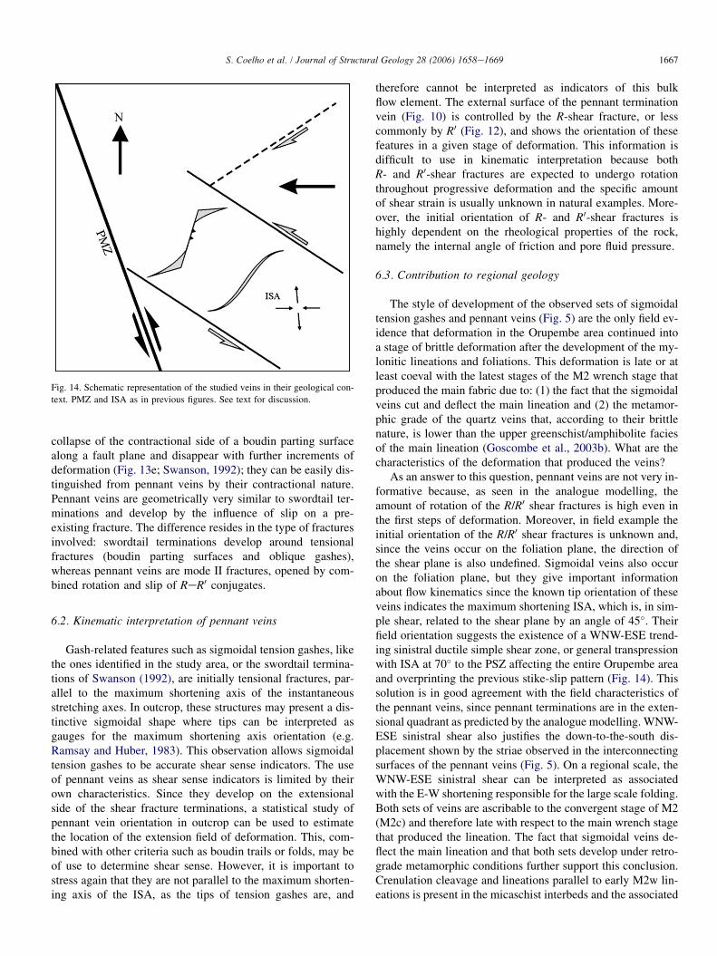
Fig. 14. Schematic representation of the studied veins in their geological con-
text. PMZ and ISA as in previous figures. See text for discussion.
therefore cannot be interpreted as indicators of this bulkflow element. The external surface of the pennant terminationvein (Fig. 10) is controlled by the R-shear fracture, or lesscommonly by R0 (Fig. 12), and shows the orientation of thesefeatures in a given stage of deformation. This information isdifficult to use in kinematic interpretation because bothR- and R0-shear fractures are expected to undergo rotationthroughout progressive deformation and the specific amountof shear strain is usually unknown in natural examples. More-over, the initial orientation of R- and R0-shear fractures ishighly dependent on the rheological properties of the rock,namely the internal angle of friction and pore fluid pressure.
6.3. Contribution to regional geology
The style of development of the observed sets of sigmoidaltension gashes and pennant veins (Fig. 5) are the only field ev-idence that deformation in the Orupembe area continued intoa stage of brittle deformation after the development of the my-lonitic lineations and foliations. This deformation is late or atleast coeval with the latest stages of the M2 wrench stage thatproduced the main fabric due to: (1) the fact that the sigmoidalveins cut and deflect the main lineation and (2) the metamor-phic grade of the quartz veins that, according to their brittlenature, is lower than the upper greenschist/amphibolite faciesof the main lineation (Goscombe et al., 2003b). What are thecharacteristics of the deformation that produced the veins?
As an answer to this question, pennant veins are not very in-formative because, as seen in the analogue modelling, theamount of rotation of the R/R0 shear fractures is high even inthe first steps of deformation. Moreover, in field example theinitial orientation of the R/R0 shear fractures is unknown and,since the veins occur on the foliation plane, the direction ofthe shear plane is also undefined. Sigmoidal veins also occuron the foliation plane, but they give important informationabout flow kinematics since the known tip orientation of theseveins indicates the maximum shortening ISA, which is, in sim-ple shear, related to the shear plane by an angle of 45�. Theirfield orientation suggests the existence of a WNW-ESE trend-ing sinistral ductile simple shear zone, or general transpressionwith ISA at 70� to the PSZ affecting the entire Orupembe areaand overprinting the previous stike-slip pattern (Fig. 14). Thissolution is in good agreement with the field characteristics ofthe pennant veins, since pennant terminations are in the exten-sional quadrant as predicted by the analogue modelling. WNW-ESE sinistral shear also justifies the down-to-the-south dis-placement shown by the striae observed in the interconnectingsurfaces of the pennant veins (Fig. 5). On a regional scale, theWNW-ESE sinistral shear can be interpreted as associatedwith the E-W shortening responsible for the large scale folding.Both sets of veins are ascribable to the convergent stage of M2(M2c) and therefore late with respect to the main wrench stagethat produced the lineation. The fact that sigmoidal veins de-flect the main lineation and that both sets develop under retro-grade metamorphic conditions further support this conclusion.Crenulation cleavage and lineations parallel to early M2w lin-eations is present in the micaschist interbeds and the associated
1668 S. Coelho et al. / Journal of Structural Geology 28 (2006) 1658e1669
folding is only visible on map scale, but the sigmoidal and pen-nant veins are the only mesoscopic evidence of M2c present inthe quartzitic layering of the study area.
7. Conclusions
This paper introduces pennant veins, a new type of vein ge-ometry with a geometry similar to established types such assigmoidal tension gashes, wing cracks and wordtail and fish-mouth termination veins. Analogue modelling has shown thatpennant terminations are controlled by the kinematics of Riedelconjugate sets of fractures. The space available for vein depo-sition is obtained by combined rotation of and slip in the oper-ating shear fractures. The orientation of pennant terminations isexpected to be in the extensional quadrant of the bulk flow and,if combined with other criteria, can be used as a shear sense in-dicator. Care has to be taken to distinguish between R-domi-nated and R0 dominated veins in such cases. However, neitherthe interconnecting nor the external surfaces of pennant veinscorrespond to the maximum shortening direction of the ISAas in tension gashes, but depend on the orientation of the R/R0 conjugate set in a given moment of deformation. Thisobservation, together with the uncertainty of the amount ofrotation of shear fractures in natural examples, hinders theuse of pennant veins as reliable gauges for bulk flow.
Acknowledgements
The experiments were preformed in LATTEX e Labora-torio de Tectonofısica e Tectonica Experimental (Universidadede Lisboa). SC is grateful for the funding provided byFundac~ao para a Ciencia e Tecnologia (SFRH/BD/12221/2003) and to Rudiger Killian and Eric de Kemp for companyduring fieldwork. CWP and SC thank the Schurmann Founda-tion for logistical support and financial aid in Namibia. Thiswork is also a contribution to TEAMINT (POCTI/CTA48137/2002). Reviews from Mark Swanson and PaulWilliams are gratefully acknowledged.
References
Ahlgren, S.G., 2001. The nucleation and evolution of Riedel shear zones as
deformation bands in porous sandstone. Journal of Structural Geology
23, 1203e1214.
Bartlett, W.L., Friedman, M., Logan, J.M., 1981. Experimental folding and
faulting of rocks under confined pressure. Part IX. Wrench faults in lime-
stone layers. Tectonophysics 79, 255e277.
Bons, P.D., 2000. The formation of veins and their microstructures. In:
Jessel, M.W., Urai, J.L. (Eds.), Stress, strain and structure, a volume in
honour of W.D. Means. Journal of the Virtual Explorer 2.
Bose, S., Marques, F.O., 2004. Controls on the geometry of tails around rigid
circular inclusions: insights from analogue modelling in simple shear.
Journal of Structural Geology 26, 2145e2156.
Braun, J., 1994. Three-dimensional numerical simulations of crustal
scale wrenching using a non-linear failure criterion. Journal of Structural
Geology 16, 1173e1186.
Cloos, E., 1955. Experimental analysis of fracture patterns. Geological Society
of America Bulletin 66, 241e256.
Cooke, M.L., 1997. Fracture lecalization along faults with spatially varying
friction. Journal of Geophysical Research 102, 22425e22434.
Cruikshank, K.M., Zhao, G., Johnson, A.M., 1991. Analysis of minor fractures
associated with joints and faulted joints. Journal of Structural Geology 13,
865e886.
Davis, G.H., Bump, A.P., Garcia, P.E., Ahlgren, S.G., 1999. Conjugate Rie-
del deformation band shear zones. Journal of Structural Geology 22,
169e190.
Dresen, G., 1991. Stress distribution and the orientation of Riedel shears.
Tectonophysics 188, 239e247.
Galland, O., de Bremond d’Ars, J., Cobbold, P.R., Hallot, E., 2003. Physical
models of magmatic intrusion during thrusting. Terra Nova 15 (6), 405e409.
Goscombe, B., Hand, M., Gray, D., 2003a. Structure of the Kaoko Belt,
Namibia: progressive evolution of a classic transpressional orogen. Journal
of Structural Geology 25, 1049e1081.
Goscombe, B., Hand, M., Gray, D., Mawby, J., 2003b. The metamorphic
architecture of a transpressional orogen: the Kaoko Belt, Namibia. Journal
of Petrology 44, 679e711.
Goscombe, B., Gray, D., Hand, M., 2005a. Extrusional tectonics in the core of
a transpressional orogen: the Kaoko Belt, Namibia. Journal of Petrology
46, 1203e1241.
Goscombe, B., Gray, D., Armstrong, R., Foster, D.A., Vogl, J., 2005b. Event
geochronology of the Pan-African Kaoko Belt, Namibia. Precambrian
Research 140, 103. e1-103-e.41.
Hanmer, S., 1986. Asymmetrical pull-aparts and foliation fish as kinematic
indicators. Journal of Structural Geology 8, 111e115.
Hilgers, C., Urai, J.L., 2002. Microstructural observations on natural syntec-
tonic fibrous veins: implications for the growth process. Tectonophysics
352, 257e274.
Hoffman, P.F., Swart, R., Freyer, E.E., Guowei, H., 1994. Damara Orogen of
Northwest Namibia. In: Niall, M., McManus, C. (Eds.), Geological
Excursion Guide of the International Conference Proterozoic Crustal and
Metallogenetic Evolution. Geological Society and Geological Survey of
Namibia, 55 pp.
Horii, H., Nemat-Nasser, S.J., 1985. Compression-induced microcracks
growth in brittle solids: axial splitting and shear failure. Journal of Geo-
physical Research 90, 3105e3125.
Katz, Y., Weinberger, R., Aydin, A., 2004. Geometry and kinematic evolution
of Riedel shear structures, Capitol Reef National Park, Utah. Journal of
Structural Geology 26, 491e501.
Kohn, D., Hilgers, C., Bons, P.D., Passchier, C.W., 2000. Numerical simula-
tions of fibre growth in antitaxial strain fringes. Journal of Structural
Geology 22, 1311e1324.
Konopasek, J., Kroner, S., Kitt, S.L., Passchier, C.W., Kroner, A., 2005. Obli-
que collision and evolution of large-scale transcurrent shear zones in the
Kaoko belt, NW Namibia. Precambrian Research 136, 139e157.
Krantz, R.W., 1991. Measurements of friction coefficients and cohesion for
faulting and fault reactivation in laboratory models using sand and sand
mixtures. In: Cobbold, P.R. (Ed.), Experimental and Numerical Modelling
of Continental Deformation. Tectonophysics 188, 203e207.
Marques, F.O., 2001. Flow and fracturing of clay: analogue experiments in
pure shear. Tectonic Modeling: A Volume in Honor of Hans Ramberg.
Geological Society of America Bulletin, Memoir 193, 261e270.
Marques, F.O., Coelho, S., 2001. Rotation of rigid elliptical cylinders in
viscous simple shear flow: analogue experiments. Journal of Structural
Geology 23, 609e617.
Marques, F.O., Bose, S., 2004. Influence of a permanent low-friction boundary
on rotation and flow in rigid inclusion/viscous-matrix systems from an
analogue perspective. Tectonophysics 382, 229e245.
Martel, S.J., Pollard, D.D., 1989. Mechanics of slip and fracture along small
faults and simple strike-slip fault zones in granitic rock. Journal of Geo-
physical Research 94, 9417e9428.
McKinnon, S.D., Garrido de la Barra, I., 1998. Fracture initiation, growth
and effect on stress field: a numerical investigation. Journal of Structural
Geology 20, 1673e1689.
Moore, D.E., Byerlee, J., 1992. Relationships between sliding behaviour and
internal geometry of laboratory fault zones and some creeping and locked
strike-slip faults of California. Tectonophysics 211, 305e316.
1669S. Coelho et al. / Journal of Structural Geology 28 (2006) 1658e1669
Moore, J.M., 1979. Tectonics of the Najd transcurrent fault system, Saudi Ara-
bia. Journal of the Geological Society of London 136, 441e454.
Naylor, M.A., Mandl, G., Sijpesteijn, C.H.K., 1986. Fault geometries in
basement-induced wrench faulting under different initial stress states.
Journal of Structural Geology 8, 737e752.
Nemat-Nasser, S., Horii, H., 1982. Compression induced nonplanar crack ex-
tension with application to splitting, exfoliation and rockburst. Journal of
Geophysical Research 87, 6805e6821.
Olson, J.E., Pollard, D.D., 1991. The initiation and growth of en echelon veins.
Journal of Structural Geology 13, 595e608.
Passchier, C.W., Trouw, R.A.J., 2005. Microtectonics, second ed. Springer-Verlag.
Passchier, C.W., Trouw, R.A.J., A. Ribeiro, A., Paciullo, F.V.P., 2002. Tectonic
evolution of the southern Kaoko belt, Namibia. Journal of African Earth
Sciences 35, 61e75.
Ramsay, J.G., Huber, M.I., 1983. The Techniques of Modern Structural
Geology. Volume 1: Strain Analysis. Academic Press, London.
Riedel, W., 1929. Zur Mechanik geologischer Brucherscheinungen. Zentral-
blatt fur Mineralogie Abteilung B, 354e368.
Schreus, G., 1994. Experiments on strike-slip faulting and block rotation.
Geology 22, 567e570.
Smith, J.V., Durney, D.W., 1992. Experimental formation of brittle
structural assemblages in oblique divergence. Tectonophysics 216,
235e253.
Swanson, M.T., 1992. Late Acadian-Alleghian transpressional deformation:
evidence from asymmetric boudinage in the Casco Bay area, coastal
Maine. Journal of Structural Geology 14, 323e341.
Tchalenko, J.S., 1968. The evolution of kink bands and the development of
compression textures in sheared clays. Tectonophysics 6, 159e174.
Weijermars, R., 1986. Flow behaviour and physical chemistry of bouncing
putties and related polymers in view of tectonic laboratory applications.
Tectonophysics 124, 325e358.
Wilcox, R.E., Harding, T.P., Seely, D.R., 1973. Basic wrench tectonics. The
American Association of Petroleum Geologists Bulletin 57, 74e96.
Willemse, E.J.M., Pollard, D.D., 1998. On the orientation and patterns of wing
cracks and solution surfaces at the tips of a sliding flaw or fault. Journal of
Geophysical Research 103, 2417e2438.