Embed Size (px)
Citation preview

De
lta
So
l®
BS
www.resol.de
Thanks for buying a RESOL.Read this manual carefully to get the best perfomance from this unit.
RESOL DeltaSol® BS
MountingConnectionHandlingFault localizationExamples
manual

DeltaSol® BS
© R
ESO
L 05
286
delta
sol_
bs.m
onen
.indd
| 2
Reprinting / copyingThis mounting- and operation manual including all parts is copyrighted. Another use outside the copyright requires the approval of RESOL - Elektronische Regelungen GmbH. This especially applies for copies, translations, micro films and the storage into electronic systems.Editor: RESOL - Elektronische Regelungen GmbH Important notice:We took a lot of care over the texts and drawings of this manual and to the best of our knowledge and consent. As faults can never be excluded, please note:Your own calculations and plans under consideration of the current norms and DIN-directions should only be basis for your projects. We don´t offer a guarantee for the completeness of the drawings and texts of this manual - they only represent some examples. They can only be used on own risk. No liability is assumed for incorrect, incomplete or false information and the resulting damages. Errors an technical changes excepted.
Safety regulations:Please read the following information carefully beforeinstalling and operating the controller. In this way damage to the solar system by wrong installation will be avoided. Please observe that the mounting is adapted to the characteristics of the building, that the local regulations are respected and is conform with the technical rules.
DIN 4757, part 1 Solar heating systems with water and water mixtures as heat transfer medium; Demands to the safety realization.DIN 4757, part 2 Solar heating systems with organic heat transfer medium; Demands to safety realization.DIN 4757, part 3 Solar heating systems; solar collectors; Meanings; safety regulations; Testing of standstil temperatureDIN 4757, part 4 Solar thermal systems; solar collectors; determination of efficiency, heat capacity and pressure loss. In addition to that European standards are worked out:PrEN 12975-1 Thermal solar systems and their components;collectors, part 1: General demands.PrEN 12975-2 Thermal solar systems and their components; collectors; part 2: Test processesPrEN 12976-1 Thermal solar systems and their components; prefabricated sys-tems, part 1: General demands.PrEN 12976-2 Thermal solar systems and their components; prefabricated sys-tems, part 2: Test processesPrEN 12977-1 Thermal solar systems and their components; Customer-designed manufactured systems, part 1: General demands.PrEN 12977-2 Thermal solar systems and their components; Customer-designed manufactured systems, part 2: Test processesPrEN 12977-3 Thermal solar systems and their components; Customer-designed manufactured systems, part 3: Performance test of warm water stores.
ContentsImprint .................................................................................2Security devices ...................................................................2Technichal data and function survey .................................31. Installation .............................................................51.1 Mounting .................................................................................. 51.2 Electrical wiring ...................................................................... 51.2.1 Standard solar system ........................................................... 61.2.2 Solar system and after-heating ............................................ 62. Operation and function ........................................72.1 Adjustment buttons .............................................................. 72.2 System monitoring display ................................................... 72.2.1 Channel indication ................................................................. 72.2.2 Tool bar .................................................................................... 7
2.2.3 System screen ......................................................................... 82.3 Blinkcodes ............................................................................... 82.3.1 System-Screen Blinkcodes ................................................... 82.3.2 Blinking codes ......................................................................... 83. Commissioning ......................................................94. Control parameter and indication channels ... 104.1 Channel overview ................................................................ 104.1.1-6 Indication channels .............................................................. 114.1.7-19 Adjustment channels ........................................................... 125. Tips for fault localization ................................... 175.1 Miscellaneous ........................................................................ 186. Accessory ............................................................ 20
DeltaSol® BS©
RES
OL
0528
6 de
ltaso
l_bs
.mon
en.in
dd
3 |
!
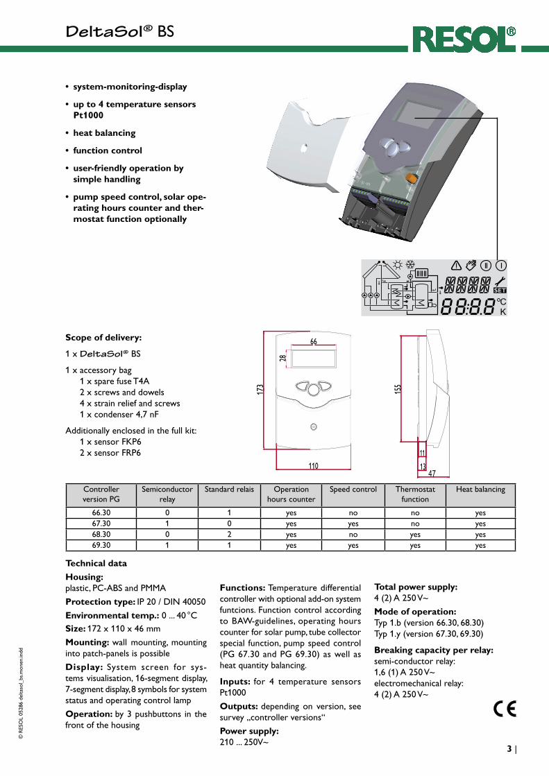
• system-monitoring-display
• up to 4 temperature sensors Pt1000
• heat balancing
• function control
• user-friendly operation by simple handling
• pump speed control, solar ope-rating hours counter and ther-mostat function optionally
Technical data
Housing: plastic, PC-ABS and PMMA
Protection type: IP 20 / DIN 40050
Environmental temp.: 0 ... 40 °CSize: 172 x 110 x 46 mm
Mounting: wall mounting, mounting into patch-panels is possible
Display: System screen for sys-tems visualisation, 16-segment display, 7-segment display, 8 symbols for system status and operating control lamp
Operation: by 3 pushbuttons in the front of the housing
Functions: Temperature differential controller with optional add-on system funtcions. Function control according to BAW-guidelines, operating hours counter for solar pump, tube collector special function, pump speed control (PG 67.30 and PG 69.30) as well as heat quantity balancing.
Inputs: for 4 temperature sensors Pt1000
Outputs: depending on version, see survey „controller versions“
Power supply: 210 ... 250 V~
Total power supply: 4 (2) A 250 V~
Mode of operation: Typ 1.b (version 66.30, 68.30) Typ 1.y (version 67.30, 69.30)
Breaking capacity per relay: semi-conductor relay: 1,6 (1) A 250 V~ electromechanical relay: 4 (2) A 250 V~
Scope of delivery:
1 x DeltaSol® BS
1 x accessory bag 1 x spare fuse T4A 2 x screws and dowels 4 x strain relief and screws 1 x condenser 4,7 nF
Additionally enclosed in the full kit: 1 x sensor FKP6 2 x sensor FRP6
Controllerversion PG
Semiconductorrelay
Standard relais Operationhours counter
Speed control Thermostatfunction
Heat balancing
66.30 0 1 yes no no yes67.30 1 0 yes yes no yes68.30 0 2 yes no yes yes69.30 1 1 yes yes yes yes

DeltaSol® BS
© R
ESO
L 05
286
delta
sol_
bs.m
onen
.indd
| 4
S1
S2S4 / TRF
1.2.1 Allocation of clamps for system 1 Standard solar system with 1 store, 1 pump and 3 sen-sors. The sensor S4 / TRF can optionally be used for heat quantity balancing.
R1
Arr 1
S3
R2
S1
S2
R1 S3
S4 / TRF
Solars ystem and after-heating with 1 store, 3 sensors and after-heating. The sensor S4 / TRF can optionally be used for heat quantity balancing.
Arr 2
1.2.2 Allocation of clamps for system 2 (PG 68.30 and PG 69.30)
Symbol SpecificationS1 collector sensorS2 store sensor belowS3 store sensor at the top
S4 / TRF sensor for heat quantitybalancing (optionally)
R1 solar pumpR2 pump for heat exchange
Symbol SpecificationS1 Collector sensorS2 Store sensor belowS3 Store sensor at the top
(optionally)S4 / TRF Sensor for heat quantity
measurement (optionally)R1 Solar pump

DeltaSol® BS©
RES
OL
0528
6 de
ltaso
l_bs
.mon
en.in
dd
5 |
Examples DeltaSol® BS
AccessoryOvervoltage protection
It is highly recommended to connect this RESOL overvoltage protection SP1 to all collector sensors in order to avoid overvoltages (e.g. by lightning).
RESOL SP1 Art.-No.: 180 110 10
Order indication
• Version 66.30: 1 standard relay, operation hours counter RESOL DeltaSol® BS / 1 115 410 10 RESOL DeltaSol® BS / 1 - full kit incl. 3 Temperature sensors Pt1000 (1 x FKP6, 2 x FRP6) 115 410 20
• Version 67.30: 1 semiconductor relay, speed control, operation hours counter RESOL DeltaSol® BS / 2 115 410 30 RESOL DeltaSol® BS / 2 - full kit incl. 3 Temperature sensors Pt1000 (1 x FKP6, 2 x FRP6) 115 410 40
• Version 68.30: 2 standard relay, thermostat function, operation hours counter RESOL DeltaSol® BS / 3 115 420 60 RESOL DeltaSol® BS / 3 - full kit incl. 3 Temperature sensors Pt1000 (1 x FKP6, 2 x FRP6) 115 410 70
• Version 69.30: 1 standard relay,1 standard relay, speed control, operation hours counter, thermostat function RESOL DeltaSol® BS / 4 115 420 80 RESOL DeltaSol® BS / 4 - full kit incl. 3 Temperature sensors Pt1000 (1 x FKP6, 2 x FRP6) 115 420 90
Please find detailed con-nection schemes for the shown systems in chap-ter 1.
Standard solar systems Solar systems with after-heating
(68.30/69.30)

DeltaSol® BS
© R
ESO
L 05
286
delta
sol_
bs.m
onen
.indd
| 6
display
pushbutton
can fuse 4A
cable conduits with strain relief
cover
2
1.1 Mounting
The unit must only be located internally. It is not suitable for installation in hazardous locations and should not be sited near to any electromagnetic field. The controller must additionally be equipped with an all-polar gap of at least 3 mm or with a gap according to the valid installaton regulations, e.g. LS-switches or fuses. Please pay attention to a separate laying of the cable lines and installation of ac power supply.
1. Unscrew the cross-recessed screw of the cover and remove it from the housing.
2. Mark the upper fastening point on the wall and premount the enclosed dowel and screw.
3. Hang up the housing at the upper fastening point and mark the lower fastening point on the underground (hole pitch 130 mm), afterwards put the lower dowel.
4. Fasten the housing at the underground.
1. InstallationWarning!Switch-off power supply before opening the housing.
1.2 Electrical wiringThe power supply to the controller must only be made by an external power supply switch (last step of installation!) and the line voltage must be 210 ... 250 Volt (50...60 Hz). Flexible lines are to be fixed at the housing by enclosed strain relief supports and screws.Depending on the version the controller is equipped with 1 relay (PG 66.30 and PG 67.30) or 2 relays (PG 68.30 and PG 69.30) to which the consumers e.g. pumps, valves etc. can be connected:• Relay 1
18 = conductor R1 17 = neutral conductor N 13 = ground clamp
• Relay 2 (PG 68.30 and 69.30) 16 = conductor R2 15 = neutral conductor N 14 = ground clamp
The temperature sensors (S1 up to S4) will be connected to the following terminals independently of the polarity:
1 / 2 = Sensor 1 (e.g. Sensor collector 1)3 / 4 = Sensor 2 (e.g. Sensor store 1)5 / 6 = Sensor 3 (e.g. Sensor TSPO)6 / 7 = Sensor 4 (e.g. Sensor TRL)The power supply is effected to the clamps:
19 = neutral conductor N20 = conductor L12 = ground clamp
net clamps
fuse
consumer clampsSensor clamps
hanging
fixation
earthing clamps
Electrostatic discharge can lead to damages of elec-tronic components!
Dangerous voltage on contact!
Please note:
The relays are semi-conductor-relays for pump speed control - they need a minimum load of 20 W (power consumption of the consu-mer) for faultless function. If auxiliary relays, motor valves, etc. are connected, the condenser which is enclosed in the mounting material, must be connected parallely to the relevant relay output. Attention: for connection of auxiliary relays or valves, the minimum pump speed must be adjusted to 100 %.
2
net clamps
fuse
consumer clampsSensor clamps earthing clamps
PG 66.30 and 67.30
PG 68.30 and 69.30

DeltaSol® BS©
RES
OL
0528
6 de
ltaso
l_bs
.mon
en.in
dd
7 |
132
backwards forward
SET(selection / adjustment mode)
The system monitoring display consists of 3 blocks: indica-tion of the channel, tool bar and system screen (active system scheme).
The indication channel consists of two lines. The upper line is an alphanumeric 16-segment indication, in which mainly the channel names / menu items are shown. In the lower 7-segment indication, the channel values and the adjustment parameter are indicated.Temperatures and temperature differences are indicated in or .
2.2.1 Channel indication
only channel indication
2.2.2 Tool bar
The additional symbols of the tool bar indicate the current system status.
only tool bar
2. Operation and function2.1 Pushbuttons for adjustment
The controller is operated by 3 pushbuttons below the display. The forward-key (1) is used for scrolling forward through the indication menu or to increase the adjustment values. The backwards-key (2) is accordingly used for the reverse function.
For adjustment of last indication channel, keep button 1 pressed for 2 seconds. If an adjustment value is shown on the display, SEt is indicated. In this case you can press the key „Set“ (3) in order to change into input mode.
Select a channel by keys 1 and 2Shortly press key 3, so that „SEt“ flashesAdjust the value by keys 1 and 2Shortly press key 3, so that „SEt“ permanently appears,the adjusted value is now saved.
2.2 System monitoring display
!
Complete Monitoring-Display
Symbol standard flashing
relay 1 active
relay 2 active
maximum store limitationactive / maximum storetemperature exceeded
collector cooling function or reccoling function active
antifreeze- function activatedcollector minimum limitation or antifreeze function active
collector security shutdown or store securtiy shutdown active
+ sensor defect
+ manual operation active
an adjustment channel is changed SET-mode

DeltaSol® BS
© R
ESO
L 05
286
delta
sol_
bs.m
onen
.indd
| 8
The system screen (active system scheme) shows the schemes selected on the controller. It consists of several system component symbols, which are - depending on the current status of the system - either flashing, permanently shown or hidden.
Sensoren
Collector 1
Collector 2
Pumps
Heating
Sensor
Additional symbol for operation of the burner
Valves
StoreStore heat exchanger Store 2 or after-heating (with additional symbol)
Sensor store top
Valves
Collectors with collector sensor
Pump
3-way-valves The flow direction or the current bre-aking capacity are always shown.
Heating circuitStore 1 and 2 with heat exchanger
After-heating with burner symbol
Temperature sensor
2.2.3 System screen
only system screen
Constantly green: everything all rightRed/green blinking: initialisation phase manual operationRed blinking: sensor defect
(sensor symbol is quickly blinking)
2.3 Blinking codes
2.3.2 LED blinking codes
2.3.1 System screen blinking codes• Pumps are blinking during starting phase• Sensors are blinking if the respective sensor-indication
channel is selected.• Sensors are quickly blinking in case of sensor defect.• Burner symbol is blinking if after-heating is activated.
DeltaSol® BS©
RES
OL
0528
6 de
ltaso
l_bs
.mon
en.in
dd
9 |
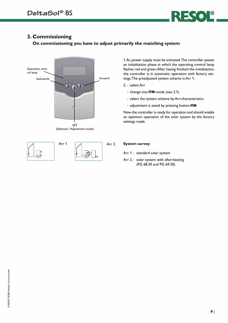
3. Commissioning On commissioning you have to adjust primarily the matching system
System survey:
Arr 1 : standard solar system
Arr 2 : solar system with after-heating (PG 68.30 and PG 69.30)
132
backwards forward
SET(Selection / Adjustment mode)
Operation cont-rol lamp
Arr 1 Arr 2
1. Ac power supply must be activated. The controller passes an initialisation phase in which the operating control lamp flashes red and green. After having finished the initialisation, the controller is in automatic operation with factory set-tings. The preadjusted system scheme is Arr 1.
2. - select Arr
- change into -mode (see 2.1)
- select the system scheme by Arr-characteristics
- adjustment is saved by pressing button
Now the controller is ready for operation and should enable an optimum operation of the solar system by the factory settings made.

DeltaSol® BS
© R
ESO
L 05
286
delta
sol_
bs.m
onen
.indd
| 10
4. Controller parameter and indication channels4.1 Channel-overview
Legend:
x
Corresponding channel is available.
x*
Corresponding channel is available if the appropriate option is activated.
Corresponding channel is only available if the option heat quantity measurement is activated (OWMZ).
MEDT
The channel antifreeze content (MED%) is only shown if a medium other than water or Tyfocor LS / G-LS (MEDT 0 or 3) is used. The adjustment is only appropriate when using other types of antifreeze.
Corresponding channel is only available if the option heat quantity measurement is deactivated (OWMZ).
Please note: S3 and S4 are only indicated if sensors are connected.
* System 2 applys only for the version 68.30 and 69.30
Only by PG 67.30 and 69.30
channelArr specification page
1 2*
COL x x Temperature collector 1 11
TST x Temperature store 1 11
TSTL x Temperature store 1 below 11
TSTU x Temperature store 1 above 11
S3 x Temperature sensor 3 11
TRF Temperature return sensor 11
S4 Temperature sensor 4 11
n % x Pump speed relay 1 11
n1 % x Pump speed relay 1 11
h P x Operating hours relay 1 11
h P1 x Operating hours relay 1 11
h P2 x Operating hours relay 2 11
kWh Heat quantity kWh 12
MWh Heat quantity MWh 12
Arr 1-2 System 9
DT O x x Switch-on temperature difference 13
DT F x x Switch-off temperature difference 13
DT S x x Nominal temperature difference 13
RIS x x Increase 13
S MX x x Maximum temperature store 1 13
EM x x emergency temperature collector 1 14
channelArr specification page
1 2
OCX x x Option collector cooling collector 1 14
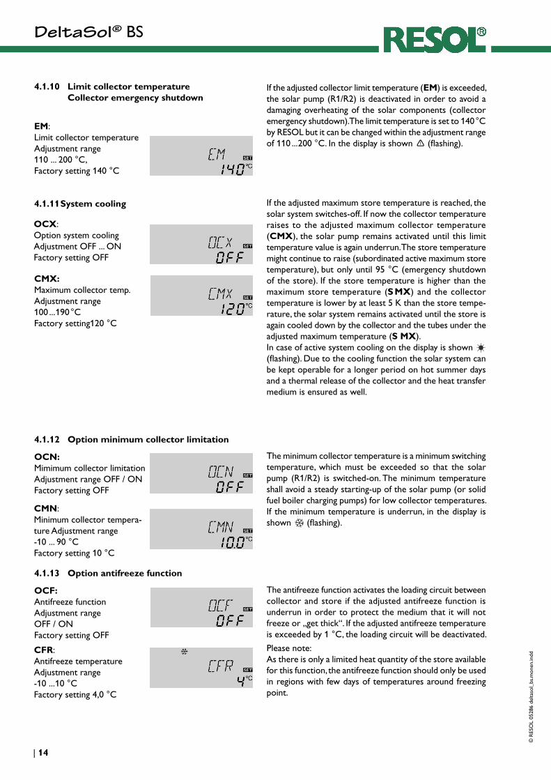
CMX x* x* Maximum temperature collector 1 14
OCN x x Option minimum limitation collector 1
14
CMN x* x* Minimun temperature collector 1 14
OCF x x Option antifreeze collector 1 14
CFR x* x* Antifreeze temperature collector 1 14
OREC x x Option reccoling 15
O TC x x Option tube collector 15
AH O x Switch-on temp. for thermostat 1 15
AH F x Switch-off temp. for thermostat 1 15
OHQM x Option WMZ 12
FMAX Maximum flow 12
MEDT Antifreeze type 12
MED% MEDT MEDT Antifreeze content 12
nMN x Minimum pump speed relay 1 16
n1MN x Minimum pump speed relay 1 16
HND x x Manual operation relay 1 16
HND2 x x Manual operation relay 2 16
LANG x x Language 16
PROG XX.XX Program number
VERS X.XX Version number
DeltaSol® BS©
RES
OL
0528
6 de
ltaso
l_bs
.mon
en.in
dd
11 |
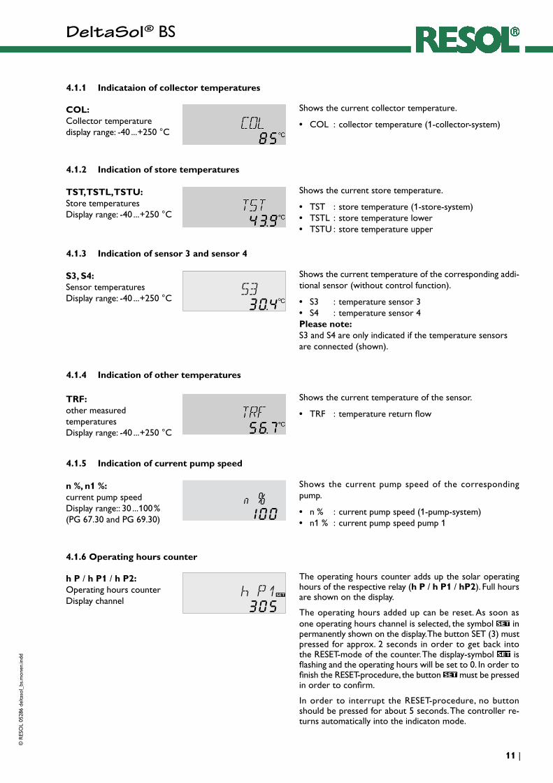
4.1.1 Indicataion of collector temperatures
Shows the current collector temperature.
• COL : collector temperature (1-collector-system)
COL:Collector temperaturedisplay range: -40 ... +250 °C
4.1.2 Indication of store temperatures
Shows the current store temperature.
• TST : store temperature (1-store-system)• TSTL : store temperature lower• TSTU : store temperature upper
TST, TSTL, TSTU:Store temperaturesDisplay range: -40 ... +250 °C
4.1.3 Indication of sensor 3 and sensor 4
Shows the current temperature of the corresponding addi-tional sensor (without control function).
• S3 : temperature sensor 3• S4 : temperature sensor 4Please note: S3 and S4 are only indicated if the temperature sensors are connected (shown).
S3, S4:Sensor temperaturesDisplay range: -40 ... +250 °C
4.1.4 Indication of other temperatures
Shows the current temperature of the sensor.
• TRF : temperature return flow
TRF:other measured temperaturesDisplay range: -40 ... +250 °C
4.1.5 Indication of current pump speed
Shows the current pump speed of the corresponding pump.
• n % : current pump speed (1-pump-system)• n1 % : current pump speed pump 1
n %, n1 %:current pump speedDisplay range:: 30 ... 100 %(PG 67.30 and PG 69.30)
4.1.6 Operating hours counter
h P / h P1 / h P2: Operating hours counter Display channel
The operating hours counter adds up the solar operating hours of the respective relay (h P / h P1 / hP2). Full hours are shown on the display.
The operating hours added up can be reset. As soon as one operating hours channel is selected, the symbol in permanently shown on the display. The button SET (3) must pressed for approx. 2 seconds in order to get back into the RESET-mode of the counter. The display-symbol is flashing and the operating hours will be set to 0. In order to finish the RESET-procedure, the button must be pressed in order to confirm.
In order to interrupt the RESET-procedure, no button should be pressed for about 5 seconds. The controller re-turns automatically into the indicaton mode.

DeltaSol® BS
© R
ESO
L 05
286
delta
sol_
bs.m
onen
.indd
| 12
4.1.7 Heat quantity balancing
OHQM:Heat quantity balan-cing Adjustment range: OFF ... ON Factory setting: OFF
A heat quantity balancing is possible for all systems in conjunction with a flowmeter. You just have to activate the option heat quantity balancing in the channel OHQM.
The volume flow readable at the flowmeter (l/min) must be adjusted in the channel FMAX. Antifreeze type and concentration of the heat transfer medium are indicated on the channels MEDT and MED%.
Type of antifreeze:0 : water 1 : propylene glycol 2 : ethylene glycol 3 : Tyfocor® LS / G-LS
FMAX: Volume flow in l/min Adjustment range 0 ... 20 in steps of 0,1 Factory setting 6,0
kWh/MWh:Heat quantity in kWh / MWh Display channel
MEDT: Type of antifreeze Adjustment range 0 ... 3 Factory setting 1
MED%: Concentration of antifreeze in (Vol-) % MED% is blinded out by MEDT 0 and 3. Adjustment range 20 ... 70 Factory setting 45
The heat quantity transported is measured by the indication of the volume flow and the reference sensor of feed flow S1 and return flow S4. It is shown in kWh-parts in the in-dication channel kWh and in MWh-parts in the indication channel MWh. The sum of both channels form the total heat output.
The heat quantity added up can be reset. As soon as one of the display channels of the heat quantity is selected, the symbol is permanently shown on the display. The button SET (3) must be pressed for approx. 2 seconds in order to get back into the RESET-mode of the counter. The display-symbol is flashing and the value for heat quantity will be set to 0. In order to finish the RESET-procedure, the button
must be pressed for confirmation.
In order to interrupt the RESET-procedure, no button should be pressed for about 5 seconds. The controller re-turns automatically into indication mode.

DeltaSol® BS©
RES
OL
0528
6 de
ltaso
l_bs
.mon
en.in
dd
13 |
4.1.8 ∆T-regulation
Please note: Switch-on temperature difference DO must be at least 1 K higher than the switch-off temperature-difference DF.
DT O: Switch-on temperature Adjustment range 1,0...20,0 K Factory setting 6.0
DT F: Switch-off temperature diff. Adjustment range 0,5 ... 19,5 K Factory setting 4.0 K
4.1.9 Maximum store temperature
If the adjusted maximum temperature is exceeded, a further loading of the store is stopped so that a damaging overheating can be avoided. If the maximum store temperature is exceeded, on the display is shown and .
Please note: The controller is equipped with a security-switch-off of the store, which avoids a further loading of the store if 95 °C are reached at the store.
S MX: Maximum store temp. Adjustment range 2..95 °C Factory setting 60 °C
DT S: Nominal temperature diffe-rence Adjustment range 1,5..30,0 K Factory setting 10.0 (PG 67.30 and 69.30)
RIS: Raise Adjustment range 1 ... 20 K Factory setting 2 K (PG 67.30 and PG 69.30)
Primarily the controller works in the same way as a standard differential controller. If the switch-on difference (DT O) is reached, the pump is activated and after having got an impulse (10 s) a minimum pump speed (nMN = 30 %) is run. If the adjusted nominal value of the temperature difference (DT S) (only PG 67.30 and PG 69.30) is reached, the pump speed is increased by one step (10%). If the difference increases by 2 K (RIS) (only PG 67.30 and PG 69.30), the pump speed is increased by 10 % respectively until the maximum pump speed of 100 % is reached. The response of the controller can be adapted by means of the parameter „Raise“. If the adjusted switch-off temperature is underrun (DT F), the controller switches-off.
DeltaSol® BS
© R
ESO
L 05
286
delta
sol_
bs.m
onen
.indd
| 14
CMN: Minimum collector tempera-ture Adjustment range -10 ... 90 °C Factory setting 10 °C
CMX: Maximum collector temp. Adjustment range 100 ... 190 °C Factory setting120 °C
4.1.11 System cooling If the adjusted maximum store temperature is reached, the solar system switches-off. If now the collector temperature raises to the adjusted maximum collector temperature (CMX), the solar pump remains activated until this limit temperature value is again underrun. The store temperature might continue to raise (subordinated active maximum store temperature), but only until 95 °C (emergency shutdown of the store). If the store temperature is higher than the maximum store temperature (S MX) and the collector temperature is lower by at least 5 K than the store tempe-rature, the solar system remains activated until the store is again cooled down by the collector and the tubes under the adjusted maximum temperature (S MX). In case of active system cooling on the display is shown (flashing). Due to the cooling function the solar system can be kept operable for a longer period on hot summer days and a thermal release of the collector and the heat transfer medium is ensured as well.
OCX: Option system cooling Adjustment OFF ... ON Factory setting OFF
4.1.12 Option minimum collector limitation
OCN: Mimimum collector limitation Adjustment range OFF / ON Factory setting OFF
The minimum collector temperature is a minimum switching temperature, which must be exceeded so that the solar pump (R1/R2) is switched-on. The minimum temperature shall avoid a steady starting-up of the solar pump (or solid fuel boiler charging pumps) for low collector temperatures. If the minimum temperature is underrun, in the display is shown (flashing).
CFR: Antifreeze temperature Adjustment range -10 ... 10 °C Factory setting 4,0 °C
4.1.13 Option antifreeze function
OCF: Antifreeze function Adjustment range OFF / ON Factory setting OFF
The antifreeze function activates the loading circuit between collector and store if the adjusted antifreeze function is underrun in order to protect the medium that it will not freeze or „get thick“. If the adjusted antifreeze temperature is exceeded by 1 °C, the loading circuit will be deactivated.
Please note:As there is only a limited heat quantity of the store available for this function, the antifreeze function should only be used in regions with few days of temperatures around freezing point.
4.1.10 Limit collector temperature Collector emergency shutdown
If the adjusted collector limit temperature (EM) is exceeded, the solar pump (R1/R2) is deactivated in order to avoid a damaging overheating of the solar components (collector emergency shutdown). The limit temperature is set to 140 °C by RESOL but it can be changed within the adjustment range of 110 ... 200 °C. In the display is shown (flashing).
EM: Limit collector temperature Adjustment range 110 ... 200 °C, Factory setting 140 °C

DeltaSol® BS©
RES
OL
0528
6 de
ltaso
l_bs
.mon
en.in
dd
15 |
4.1.15 Tube collector special function If the controller measures an increase of 2 K compared to the collector temperature stored at last, the solar pump is switched-on to 100 % for about 30 seconds. After expiration of the solar pump runtime the current collector temperature is stored as new reference value. If the measured temperature (new reference value) is again exceeded by 2 K, the solar pump again switches-on for 30 seconds. If the switch-on difference between collector and store is again exceeded during runtime of the solar pump or the standstil of the system, the controller automatically switches over to solar charging.If the collector temperature drops by 2 K during standstill, the switch-on value for the special tube collector function will be recalculated.
O TC: Tube collector special function Adjustment range: OFF ... ON Factory setting: OFF
4.1.14 Recooling function If the adjustem maximum store temperature (S MX) is reached, the solar pump remains activated in order to avoid an overheating of the collector. The store temperature might continue to increase but only up to 95 °C (emergency shutdown of the store).In the evening the solar system continues running until the store is cooled down to the adjusted maximum store temperature via collector and pipes.
OREC: option recooling adjustment range OFF ... ON Factory setting: OFF
The thermostat function works independently from the solar operation and can e.g. be used for use of surplus energy or an after-heating.
• AH O < AH F the thermostat function is used for after-heating
• AH O > AH F the thermostat function is used for use of surplus energy
On the display is shown if the second relay output is activated.
4.1.16 Thermostat function (Arr = 2)
after-heating use of surpluse energy
AH O:Thermostat-switch-on temperatureAdjustment range: 0,0 ... 95,0 °CFactory setting: 40,0 °C
AH F:Thermostat-switch-off tem-peratureAdjustment range: 0,0 ... 95,0 °CFactory setting: 45,0 °C

DeltaSol® BS
© R
ESO
L 05
286
delta
sol_
bs.m
onen
.indd
| 16
For control and service work the operating mode of the controller can be manually adjusted by selecting the adjust-ment value HAND / HND1 / HND2, in which the following adjustments can be made:
4.1.18 Operating mode
• HAND / HND1 / HND2 Operating mode OFF : relay off (flashing) + AUTO : relay in automatic operation ON : relay on (flashing) +
HAND / HND1 / HND2:Operating mode Adjustment range: OFF, AUTO, ONFactory setting: AUTO
4.1.17 Pump speed controlA relative minimum pump speed is specified for pumps connected at the outputs R1 and R2 via adjustment channel nMN.
Attention:
When using consumers (e.g. valves) which are not pump speed controlled, the value must be adjusted to 100 % in order to deactivate the pump speed control.
nMN:Pump speed controlAdjustment range: 30 ... 100Factory setting: 30 (PG 67.30 and PG 69.30)
4.1.19 Language
The menu language can be adjusted in this channel.
• dE : German• En : English• It : Italiano
LANG:Adjustment of languageAdjustment range: dE, En, ItFactory setting: En

DeltaSol® BS©
RES
OL
0528
6 de
ltaso
l_bs
.mon
en.in
dd
17 |
5. Tips for fault localization
can fuse T4A If a malfunction occurs, a notification is given on the display of the controller:
Operating control lamp
Warning symbol
2
Operating control lamp off
The power supply of the controller should be checked if the control lamp goes out.
o.k.no
The can fuse of the controller is defective. It can be replaced after removal of the front cover (spare fuse is enclosed in the accessory bag).
Operating control lamp flashes red. On the display appears the symbol and the symbol .
Sensor defect. An error code is shown on the relevant sensor indication channel instead of a temperature.
- 88.8888.8
Line break. Check the line.
Short-circuit. Check the line.
Pt1000-temperature sensors pinched off can be checked with an ohmmeter. In the following the resistance values corresponding to different temperatures are listed.
Resistance values of the Pt1000-sensors

DeltaSol® BS
© R
ESO
L 05
286
delta
sol_
bs.m
onen
.indd
| 18
Pump starts for a short moment, switches-off, switches-on again, etc. („controller hunting“)
Is the temperature diffe-rence at the controller too small?
no yes
Wrong placing of the collector sensor?
yes
Change ∆Ton and ∆Toff accordingly.
Mount the collector sen-sor at solar feed flow (warmest collector out-put); use the immersion sleeve of the respective collector.
Pump starts up very late and soon stops working soon. The temperature difference between store and collector increases enormously during operation; the collector cir-cuit cannot dissipate the heat.
Collector circuit pump defect ?
no yes
Heat exchanger calcified?
yes
Control / replace
Decalificationno
Heat exchanger plugged?
yesno Cleaning
Heat exchanger too small?
yes New calculation of the dimension.
no
Plausibility control of the option tube collector spe-cial function?
Change ∆Ton and ∆Toff accordingly.
Switch-on-temperatu-re difference ∆Ton too large?
no yes
Collector sensor unfavour-able placed (e.g. contact sensor instead of immersion sleeve sensor?
o.k.no
Pump is overheated, but no heat transfer from collector to the store, feed flow and return flow are equally warm, perhaps also bubble in the lines.
Exhaust the system; in-crease system pressure to at least static primary pressure plus 0,5 bar; if necessary continue to increase, switch the pump for a short time off and on.
Air in the system?
no yes
Is the collector circuit plugged at the dirt trap?
yes
Clean the dirt trap
5.1Various:
If necessary activate tube collector function.
yes
o.k.

DeltaSol® BS©
RES
OL
0528
6 de
ltaso
l_bs
.mon
en.in
dd
19 |
Stores are cooled during the night.
Does collector circuit pump run during the night?
no yesCheck the controller functions
Collector temperature is at night higher than ambi-ent temperature.
no yes
Check the return flow preventer in feed flow and return flow with regard to the functional efficiency.
Is store insulation suffi-cient?
yes noIntensify the insulation.
Is store insulation close enough to the store?
yes no
Replace or intensify the insulation.
Are the store connec-tions insulated?
yes no Insulate connections.
Warm water outflow upwards?
no yes
Change connection and let the water flow side-wards or through a siphon (bow downwards); less store losses now?
Does warm water circu-lation run for a very long time?
no yes
Use the circulation pump with timer and switch-off thermostat (energy effi-cient circulation)
The solar circuit pump does not work although the coll-ector is obviously warmer than the store.
Does the control LED flash?
yes no
Does the pump start up in manual operation?
yes
There is no current; check fuses / replace them and check power supply.
The adjusted temperature difference for starting the pump is too high; choose an matching settingno
Is the current of the pump released by the controller?
yes
Is the pump stuck?
Put the pump into operati-on by means of a screwdri-ver; is it passable now ?
Is the pump defective - replace it.
Are the fuses of the controller o.k.?
Controller seems to be defective - replace it.
no yes
no
no yes
Replace the fuses.
Switch-off the circulation pump and the blocking valve for 1 night; less store losses?
yes no
Check the pumps of the after-heating circuit ac-cording to nightly run and defect return flow preven-ter; problem solved?
no
no yes
o.k.
Control the return flow preventer in warm water circulation- o.k.
yes no
Please also check further pumps which are connec-ted to the solar store.
The gravitation circulation in the circulation line is too strong; insert a stron-ger return flow preventer or an electrical 2-way val-ve behind the circulation pump; the 2-way valve is open in pump operati-on, otherwise it is closed, conect pump and 2-way
Cleaning or replacement.
valve in parallel; activate the circulation again!
a
a b
b

DeltaSol® BS
© R
ESO
L 05
286
delta
sol_
bs.m
onen
.indd
| 20
Distributed by:
Please note:The design and the specifications are to be changed without notice.The illustrations may differ from original product.
RESOL - Elektronische Regelungen GmbH
Heiskampstraße 10 D - 45527 Hattingen
Tel.: +49 (0) 23 24 / 96 48 - 0 Fax: +49 (0) 23 24 / 96 48 - 55
www.resol.de [email protected]
6. Accessory
Overvoltage protection
We highly recommend to install the RESOL overvoltage protection in order to avoid overvoltage damages at the collector (e.g. by lightening).
Sensors
Our product range includes high-precision platin temperatu-re sensors, flatscrew sensors, ambient temperature sensors, indoor temperature sensors, cylindrical clip-on sensors and irradiation sensors, also to be used as full sensors with sensor pocket.
Flowmeter
If you are interested in realising a heat quantity balancing, you need a flowmeter for measuring the volume flow in your system.