Embed Size (px)
Citation preview
Research on Force Sensing and Zero Gravity MotionSimulation Technology of Industrial RobotRuiqin Hu ( [email protected] )
Beijing Institute of Spacecraft Environment Engineering https://orcid.org/0000-0003-3114-6689Shaohua Meng
Beijing Institude of SpaceCraft Environment EngineeringLijian Zhang
Beijing Institute of Spacecraft Environmental Engineering: China Academy of Space TechnologyDepartment of Spacecraft Environmental EngineeringQue Dong
Beijing Institude of Spacecraft Environment EngineeringChengli Zhang
Beijing Institude of Spacecraft Environment Engineering
Original Article
Keywords: Force-feedback, Zero-gravity simulation, BP neural network, Robot control
Posted Date: August 6th, 2021
DOI: https://doi.org/10.21203/rs.3.rs-762971/v1
License: This work is licensed under a Creative Commons Attribution 4.0 International License. Read Full License
·1·
Title page
Research on Force Sensing and Zero Gravity Motion Simulation Technology of Industrial
Robot
Rui-Qin Hu, born in 1988, is currently an engineer at Beijing Institute of Spacecraft Environment Engineering, China. He received his
master degree from Tsinghua University, China, in 2013. His research interests include spacecraft integretion and test, intelligent
robotics and machine learning.
E-mail: [email protected]
Shao-Huan Meng, born in 1985, is currently an engineer at Beijing Institute of Spacecraft Environment Engineering, China. He
received his PhD degree from Beihang University, China, in 2015.
Li-Jian Zhang, born in 1983, is currently an engineer at Beijing Institute of Spacecraft Environment Engineering, China. He received
his master degree from Harbin Institute of Technology, China, in 2007.
Que Dong, born in 1983, is currently an engineer at Beijing Institute of Spacecraft Environment Engineering, China. He received his
PhD degree from Beijing Institute of Technology, China, in 2015.
Cheng-Li Zhang, born in 1982, is currently an an engineer at Beijing Institute of Spacecraft Environment Engineering, China. He
received his master degree from Harbin Institute of Technology, China, in 2008.
Corresponding author:Rui-Qin Hu E-mail:[email protected]
Rui-Qin Hu et al.
·2·
ORIGINAL ARTICLE
Research on Force Sensing and Zero Gravity Motion Simulation Technology of
Industrial Robot Rui-Qin Hu1, 2 • Shao-Huan Meng1, 2 • Li-Jian Zhang1, 2 • Que Dong1, 2 • Cheng-Li Zhang1, 2
Received June xx, 201x; revised February xx, 201x; accepted March xx, 201x
© Chinese Mechanical Engineering Society and Springer-Verlag Berlin Heidelberg 2017
Abstract: Towards the zero-gravity simulation test
requirements of spacecraft for on-orbit service missions,
the zero-gravity motion simulation technology based on
industrial robot was studied. In order to realize the accurate
force sensing of load on robot, the BP neural network was
used to establish the force prediction model. The model
uses the robot pose, acceleration, angular velocity, and
angular acceleration as input layer parameters, and uses the
data from force/torque sensor on robot wrist as the output
layer parameter. In order to realize the accurate force
perception in whole working space of the robot, the
orthogonal experiment design method was adopted to
determine the path points of the robot for sample data
collection. Based on the established force prediction model,
the accurate force sensing of the end load of the robot
under moving conditions is realized. In experiment, for the
load with 100kg mass on robot, the maximum error of
force sensing is 39.8N, and the root mean square error of
force sensing is 9.3N. The maximum error of torque
sensing is 18.7Nm, and the root mean square error of
torque sensing is 4.4Nm. Furthermore, according to the
real-time force sensing results of the robot load, the motion
speed of the load in zero-gravity state is calculated by
dynamics theory. Then the robot is driven to execute the
corresponding motion of the load, and the zero gravity
motion simulation of the load is realized.
Keywords: Force-feedback • Zero-gravity simulation • BP
Rui-Qin Hu
1 Beijing Institute of Spacecraft Environment Engineering, Beijing
100094, China
2 Beijing Engineering Research Center of the Intelligent Assembly
Technology and Equipment for Aerospace Product, Beijing 100094,
China
neural network • Robot control
1 Introduction
On-orbit servicing (OOS) usually refers to the space
assembly, maintenance and service that can extend the life
or enhance the capability of spacecraft through human,
robot or both in space [1]. In order to make the system
adapt to the space environment with microgravity, vacuum,
radiation etc., it is an effective measure to improve the
success rate of space flight to carry out sufficient test
verification on the ground. For the ground simulation of
OOS technology, zero gravity simulation is the key and
difficult point. At present, there are several kinds of zero
gravity simulation methods, including freefall, parabolic
flight, air bearing, neutral buoyancy, force compensation
and hardware in loop (HIL) [2].
The HIL method combines the prototype with the
mathematical model, which is a semi-physical simulation
method, and can be used for the ground experiment of
space mechanism [3-6]. It accurately measures the force of
the simulated object in real time, further calculates the
motion of the object in zero gravity environment with the
help of dynamic model, and then realizes the motion by the
robot [7]. Accurate force sensing is the premise of accurate
motion simulation [8].
For the realization of zero gravity motion of robot, the
existing technology mainly includes two ways.
One method is to carry out force-free control for the
robot [9], which is necessary to identify the mass
characteristics of each part of the robot, and establish the
dynamic model of the robot, so as to realize the prediction
of the joint torque in the process of robot movement
[10-12]. The joint torque is collected in real time during
Novel 6-DOF Wearable Exoskeleton Arm with Pneumatic Force-Feedback for Bilateral Teleoperation
·3·
the operation of the robot, and the contact force on the
robot is obtained by comparing the actual joint torque with
the predicted torque, And drive the robot to achieve
zero-gravity movement. This method does not need
additional sensors for the robot, but an important problem
of this method is that the joint friction torque can not be
accurately measured or predicted [13]. For heavy load on
robot, it is difficult to achieve an accurate force sensing
result. This method is usually used in the direct teaching of
robot with light load.
Another method is installing a 6-axis force/torque(F/T)
sensor on the wrist of the robot. The F/T Sensor can
accurately measure the three-dimensional orthogonal force
(Fx, Fy, Fz) and three-dimensional orthogonal torque (Mx,
My, Mz) in any force system in the space. For the robot
with heavy load, it can still obtain high measurement
resolution and can achieve more accurate simulation for
zero gravity motion.
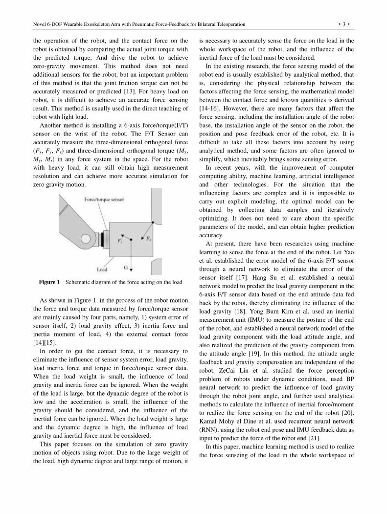
Figure 1 Schematic diagram of the force acting on the load
As shown in Figure 1, in the process of the robot motion,
the force and torque data measured by force/torque sensor
are mainly caused by four parts, namely, 1) system error of
sensor itself, 2) load gravity effect, 3) inertia force and
inertia moment of load, 4) the external contact force
[14][15].
In order to get the contact force, it is necessary to
eliminate the influence of sensor system error, load gravity,
load inertia force and torque in force/torque sensor data.
When the load weight is small, the influence of load
gravity and inertia force can be ignored. When the weight
of the load is large, but the dynamic degree of the robot is
low and the acceleration is small, the influence of the
gravity should be considered, and the influence of the
inertial force can be ignored. When the load weight is large
and the dynamic degree is high, the influence of load
gravity and inertial force must be considered.
This paper focuses on the simulation of zero gravity
motion of objects using robot. Due to the large weight of
the load, high dynamic degree and large range of motion, it
is necessary to accurately sense the force on the load in the
whole workspace of the robot, and the influence of the
inertial force of the load must be considered.
In the existing research, the force sensing model of the
robot end is usually established by analytical method, that
is, considering the physical relationship between the
factors affecting the force sensing, the mathematical model
between the contact force and known quantities is derived
[14-16]. However, there are many factors that affect the
force sensing, including the installation angle of the robot
base, the installation angle of the sensor on the robot, the
position and pose feedback error of the robot, etc. It is
difficult to take all these factors into account by using
analytical method, and some factors are often ignored to
simplify, which inevitably brings some sensing error.
In recent years, with the improvement of computer
computing ability, machine learning, artificial intelligence
and other technologies. For the situation that the
influencing factors are complex and it is impossible to
carry out explicit modeling, the optimal model can be
obtained by collecting data samples and iteratively
optimizing. It does not need to care about the specific
parameters of the model, and can obtain higher prediction
accuracy.
At present, there have been researches using machine
learning to sense the force at the end of the robot. Lei Yao
et al. established the error model of the 6-axis F/T sensor
through a neural network to eliminate the error of the
sensor itself [17]. Hang Su et al. established a neural
network model to predict the load gravity component in the
6-axis F/T sensor data based on the end attitude data fed
back by the robot, thereby eliminating the influence of the
load gravity [18]. Yong Bum Kim et al. used an inertial
measurement unit (IMU) to measure the posture of the end
of the robot, and established a neural network model of the
load gravity component with the load attitude angle, and
also realized the prediction of the gravity component from
the attitude angle [19]. In this method, the attitude angle
feedback and gravity compensation are independent of the
robot. ZeCai Lin et al. studied the force perception
problem of robots under dynamic conditions, used BP
neural network to predict the influence of load gravity
through the robot joint angle, and further used analytical
methods to calculate the influence of inertial force/moment
to realize the force sensing on the end of the robot [20].
Kamal Mohy el Dine et al. used recurrent neural network
(RNN), using the robot end pose and IMU feedback data as
input to predict the force of the robot end [21].
In this paper, machine learning method is used to realize
the force senseing of the load in the whole workspace of
Rui-Qin Hu et al.
·4·
robot, aiming to solve the problem that traditional
analytical method is difficult to achieve. The BP neural
network is used in research, the end position and attitude
data of the robot, the acceleration and angular velocity data
fed back by IMU, and the angular acceleration data from
the difference of angular velocity were used as input, The
output of the F/T sensor when the load is not subjected to
external force was used as output. Compared with the
existing studies, this study introduces the angular
acceleration information obtained from the difference of
IMU angular velocity data in the input layer, because the
theoretical analysis shows that the inertia moment caused
by load rotation is directly related to its angular
acceleration. On the other hand, this study takes the
position and attitude information of the robot end as a part
of the input layer parameters, and covers the whole
workspace of the robot as much as possible in the sampling,
so that the trained model can obtain high accuracy in the
whole workspace of the robot and meet the large-scale
motion requirements of zero gravity motion simulation. the
prediction model of the end force can be obtained through
training. When the robot end is subjected to contact force,
using the actual measurement value of the F/T sensor
minus the predicted value, the contact force can be
obtained. On the basis of realizing the dynamic force
sensing of the robot end load, further combined with the
dynamic theory, according to the force sensing data of the
robot end in real time, the motion speed of the robot end
load under zero gravity can be calculated, and the robot is
driven to perform the corresponding motion, so as to
realize the zero gravity motion simulation of the load.
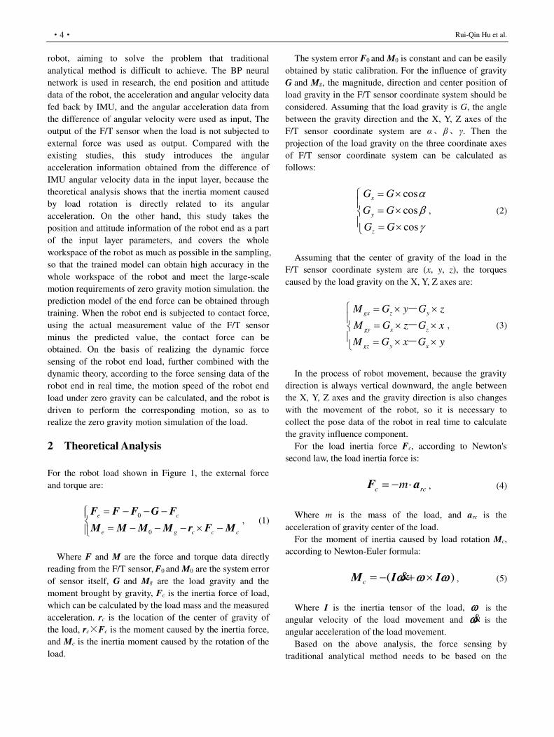
2 Theoretical Analysis
For the robot load shown in Figure 1, the external force
and torque are:
0
0
e c
e g c c c
F F F G F
M M M M r F M, (1)
Where F and M are the force and torque data directly
reading from the F/T sensor, F0
and M0 are the system error
of sensor itself, G and Mg are the load gravity and the
moment brought by gravity, Fc is the inertia force of load,
which can be calculated by the load mass and the measured
acceleration. rc is the location of the center of gravity of
the load, rc×Fc is the moment caused by the inertia force,
and Mc is the inertia moment caused by the rotation of the
load.
The system error F0 and M0 is constant and can be easily
obtained by static calibration. For the influence of gravity
G and Mg, the magnitude, direction and center position of
load gravity in the F/T sensor coordinate system should be
considered. Assuming that the load gravity is G, the angle
between the gravity direction and the X, Y, Z axes of the
F/T sensor coordinate system are α、β、γ. Then the
projection of the load gravity on the three coordinate axes
of F/T sensor coordinate system can be calculated as
follows:
cos
cos
cos
x
y
z
G G
G G
G G
, (2)
Assuming that the center of gravity of the load in the
F/T sensor coordinate system are (x, y, z), the torques
caused by the load gravity on the X, Y, Z axes are:
gx z y
gy x z
gz y x
M G y G z
M G z G x
M G x G y
-
-
-
, (3)
In the process of robot movement, because the gravity
direction is always vertical downward, the angle between
the X, Y, Z axes and the gravity direction is also changes
with the movement of the robot, so it is necessary to
collect the pose data of the robot in real time to calculate
the gravity influence component.
For the load inertia force Fc, according to Newton's
second law, the load inertia force is:
c rcm F a , (4)
Where m is the mass of the load, and arc is the
acceleration of gravity center of the load.
For the moment of inertia caused by load rotation Mc,
according to Newton-Euler formula:
( )c M I I& , (5)
Where I is the inertia tensor of the load, is the
angular velocity of the load movement and & is the
angular acceleration of the load movement.
Based on the above analysis, the force sensing by
traditional analytical method needs to be based on the
Novel 6-DOF Wearable Exoskeleton Arm with Pneumatic Force-Feedback for Bilateral Teleoperation
·5·
following data:
1) Constant data:
a) The system error of sensor.
b) The installation angle of robot base and the
installation angle of sensor on the robot.
c) The mass and the center of gravity of the load.
d) The inertia tensor of the load.
2) Variable data:
a) Data of F/T sensor.
b) Pose of robot.
c) Acceleration, angular velocity and angular
acceleration of load.
For the above variables, the pose of the robot can be
obtained by the robot control system in real time. For the
industrial robot in series structure form, due to its
structural characteristics, the pose feedback from the robot
controller often has a large error. The acceleration, angular
velocity and angular acceleration of load movement can be
obtained by conversion of attitude and speed feedback
from the robot, and can also be measured by IMU and
other sensors.
For the above constant data, the installation angle of
robot base and the installation angle of sensor on the robot
need to be measured and calibrated in advance, or the
installation accuracy can be ensured by mechanical
positioning. The other constants need to be identified in
advance, especially for the load inertia tensor, which is
difficult to identify accurately, its identification error will
affect the final force sensing error.
If using analytical method, the above constant needs to
be calibrated in advance, and the above variables are
accurately collected during the robot motion. However,
because some constants (such as inertia tensors) are
difficult to be accurately measured, and some variables
(such as robot pose) have large errors and are difficult to
be accurately measured and compensated, so it is difficult
to meet the precise force sensing requirements of robot
under the condition of large load, high dynamic and large
range of motion.
If machine learning is adopted, the above variables are
collected directly under the condition that the load is not
subjected to external force. The data of the F/T sensor is
taken as the output, and the other variables are taken as the
input. Because the robot end is not subject to external force,
the output prediction value of each group of sample input
pairs shall be equal to the measured value of the F/T sensor.
By collecting the data samples of robot in different motion
states in the whole workspace, the machine learning model
can be trained iteratively, and the prediction model of the
end force can be obtained. When the robot end is subjected
to external force, using the actual measurement value of
the F/T sensor minus the predicted value of the machine
learning model can obtain the information of external force,
which realize the force sensing of the load. This method
does not need to pre-calibrate the above constants, and can
also accurately fit the nonlinear errors (such as robot pose
errors) which are difficult to be modeled analytically.
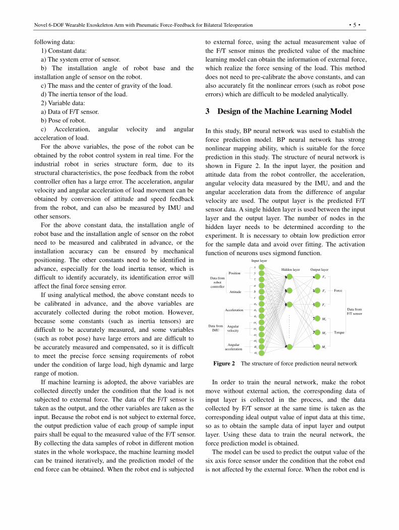
3 Design of the Machine Learning Model
In this study, BP neural network was used to establish the
force prediction model. BP neural network has strong
nonlinear mapping ability, which is suitable for the force
prediction in this study. The structure of neural network is
shown in Figure 2. In the input layer, the position and
attitude data from the robot controller, the acceleration,
angular velocity data measured by the IMU, and and the
angular acceleration data from the difference of angular
velocity are used. The output layer is the predicted F/T
sensor data. A single hidden layer is used between the input
layer and the output layer. The number of nodes in the
hidden layer needs to be determined according to the
experiment. It is necessary to obtain low prediction error
for the sample data and avoid over fitting. The activation
function of neurons uses sigmond function. Input layer
Hidden layer Output layerx
y
z
a
b
c
ax
ay
az
x
y
z
x
y
z
Fx
Fy
Fz
Mx
My
Mz
Position
Attitude
Acceleration
Angular
velocity
Angular
acceleration
Data from
F/T sensor
Data from
robot
controller
Data from
IMU
Force
Torque
Figure 2 The structure of force prediction neural network
In order to train the neural network, make the robot
move without external action, the corresponding data of
input layer is collected in the process, and the data
collected by F/T sensor at the same time is taken as the
corresponding ideal output value of input data at this time,
so as to obtain the sample data of input layer and output
layer. Using these data to train the neural network, the
force prediction model is obtained.
The model can be used to predict the output value of the
six axis force sensor under the condition that the robot end
is not affected by the external force. When the robot end is

Rui-Qin Hu et al.
·6·
affected by the external force, the external force
information can be obtained by subtracting the predicted
value from the actual measured value, so as to realize the
force perception of the end load of the robot.
4 Realization of Force Sensing
4.1 System Composition
Robot
F/T sensor
LoadIMU
Figure 3 Schematic diagram of robot force sensing test system
The composition of the test system is shown in Figure 3.
The F/T sensor is installed at the wrist of the robot, and the
IMU is installed at the end of the robot. The robot adopts
KR210 robot of KUKA company, and its main parameters
are shown in Table 1. The F/T sensor adopts Omega191
sensor of ATI company, and its measurement range and
resolution parameters are shown in Table 2.
Table 1 Performance parameters of KR210 robot
Attribute Rated
payload
Number
of axes
Maximum
reach
Pose
repeatability
Value 210kg 6 2696mm 0.06mm
Table 2 Technical parameters of Omega191 F/T sensor
Attribute Fx
/(N)
Fy
/(N)
Fz
/(N)
Tx
/(Nm)
Ty
/(Nm)
Tz
/(Nm)
Measuring
range
-7200
~7200
-7200
~7200
-18000
~18000
-1400
~1400
-1400
~1400
-1400
~1400
Resolution 3/8 3/8 5/8 5/96 5/96 5/144
Table 3 Technical parameters of STIM300 IMU
Parameter Value
Measurement range of angular velocity ±400 °/s
Angular velocity resolution 0.22°/h
Acceleration measurement range ±10g
Acceleration measurement resolution 1.9ug
Sampling frequency 2000Hz
The IMU adopts the STIM300 of Sensonor company.
The sensor adopts three high-precision MEMS gyroscopes
and MEMS accelerometers to measure the angular velocity
and acceleration data of X, Y and Z axes respectively. The
main technical parameters are shown in Table 3.
The IMU can directly measure the acceleration and
angular velocity of the motion. From the above theoretical
analysis, it can be seen that the angular acceleration of the
load is also needed to calculate the inertial moment of the
load. Therefore, the angular velocity data sequence of the
IMU is differentiated to obtain the angular acceleration
data.
The real object of the test system is shown in Figure 4.
The IMU is installed in the adapter between the end of the
robot and the F/T sensor, which makes the system more
compact in practical application and avoids additional
interference in the robot motion. The weight of the robot
load is about 100kg.
Figure 4 The real object of the force sensing test system
4.2 Collection of Sample Data
In order to make the sample data cover the entire
workspace of the robot as much as possible, while
reducing the total number of samples and improving the
efficiency of model training, the orthogonal experimental
design method was adopted in the research. For the six
rotation axes A1~A6 of the robot, 10 angle values are
uniformly selected within their respective rotation ranges.
The value of the rotation range of each axis should be as
large as possible, but also to ensure that the robot does not
collide during the sample collection movement. The
rotation ranges of each axis are shown in Table 4.
Table 4 Rotation ranges of each axis in experiment
Axis A1 A2 A3 A4 A5 A6
Rotation
range
-150
~150
-138
~-70
-10
~130
-180
~180
-120
~120
-180
~180
According to the orthogonal experiment design method,
the angle value of A1~A6 axis is used as 6 factors of the
Novel 6-DOF Wearable Exoskeleton Arm with Pneumatic Force-Feedback for Bilateral Teleoperation
·7·
experiment, and the angle value of each axis is divided into
10 levels. During the sample collection process, the angle
of each axis of the robot path point is determined
according to the L141 (106) orthogonal table.
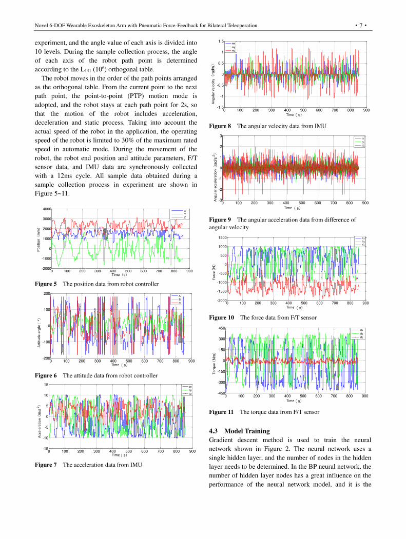
The robot moves in the order of the path points arranged
as the orthogonal table. From the current point to the next
path point, the point-to-point (PTP) motion mode is
adopted, and the robot stays at each path point for 2s, so
that the motion of the robot includes acceleration,
deceleration and static process. Taking into account the
actual speed of the robot in the application, the operating
speed of the robot is limited to 30% of the maximum rated
speed in automatic mode. During the movement of the
robot, the robot end position and attitude parameters, F/T
sensor data, and IMU data are synchronously collected
with a 12ms cycle. All sample data obtained during a
sample collection process in experiment are shown in
Figure 5~11.
Figure 5 The position data from robot controller
Figure 6 The attitude data from robot controller
Figure 7 The acceleration data from IMU
Figure 8 The angular velocity data from IMU
Figure 9 The angular acceleration data from difference of
angular velocity
Figure 10 The force data from F/T sensor
Figure 11 The torque data from F/T sensor
4.3 Model Training
Gradient descent method is used to train the neural
network shown in Figure 2. The neural network uses a
single hidden layer, and the number of nodes in the hidden
layer needs to be determined. In the BP neural network, the
number of hidden layer nodes has a great influence on the
performance of the neural network model, and it is the
0 100 200 300 400 500 600 700 800 900-2000
-1000
0
1000
2000
3000
4000
Time(s)
Positio
n(
mm)
X
Y
Z
0 100 200 300 400 500 600 700 800 900-200
-100
0
100
200
时间(s)
姿态角(
°)
A
B
C
Time
Att
itu
de
an
gle
0 100 200 300 400 500 600 700 800 900-15
-10
-5
0
5
10
15
时间(s)
加速度(
m/s
2)
ax
ay
az
Time
Acc
ele
rati
on
0 100 200 300 400 500 600 700 800 900-1.5
-1
-0.5
0
0.5
1
1.5
时间(s)
角速度(
rad/s)
wx
wy
wz
Time
An
gu
lar
ve
loci
ty
0 100 200 300 400 500 600 700 800 900-3
-2
-1
0
1
2
3
时间(s)
角加速度(
rad/s
2)
rx
ry
rz
Time
An
gu
lar
acc
ele
rati
on
0 100 200 300 400 500 600 700 800 900-2000
-1500
-1000
-500
0
500
1000
1500
时间(s)
力(
N)
Fx
Fy
Fz
Time
Fo
rce
0 100 200 300 400 500 600 700 800 900-450
-300
-150
0
150
300
450
时间(s)
力矩(
Nm)
Mx
My
Mz
Time
To
rqu
e
Rui-Qin Hu et al.
·8·
direct cause of overfitting. In order to avoid the
phenomenon of overfitting during training as much as
possible, and to ensure sufficiently high performance and
generalization ability, the structure should be as compact as
possible, and the number of hidden layer nodes should be
as few as possible on the premise of meeting the accuracy
requirements.
During training, the data samples are divided into
training set, validation set and test set. The training set
accounts for 60% of the total number of samples, the
validation set and the test set account for 20% respectively,
and 3 subsets of data are randomly selected. The training
set is used to train the model, the validation set is used to
evaluate the prediction of the model and adjust the
corresponding parameters, and the test set is used to test
the generalization ability of the trained model for new data.
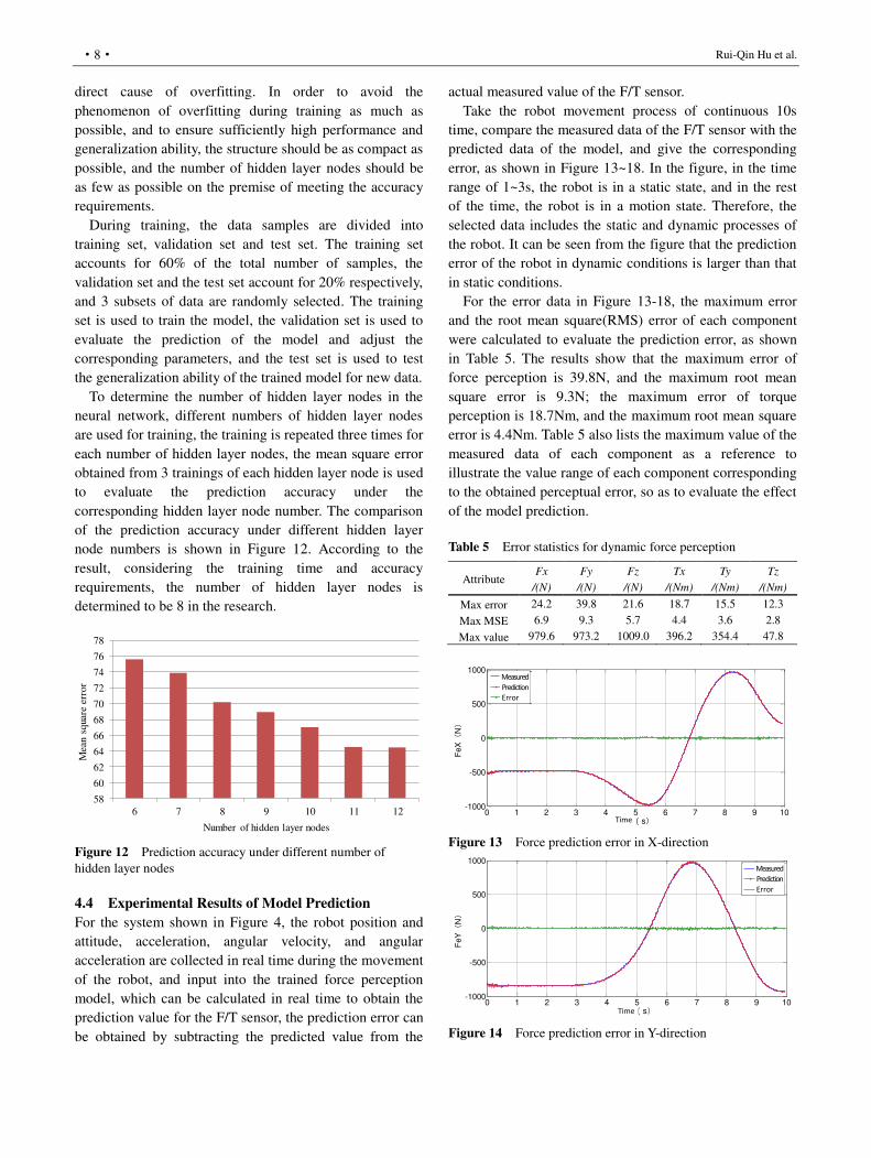
To determine the number of hidden layer nodes in the
neural network, different numbers of hidden layer nodes
are used for training, the training is repeated three times for
each number of hidden layer nodes, the mean square error
obtained from 3 trainings of each hidden layer node is used
to evaluate the prediction accuracy under the
corresponding hidden layer node number. The comparison
of the prediction accuracy under different hidden layer
node numbers is shown in Figure 12. According to the
result, considering the training time and accuracy
requirements, the number of hidden layer nodes is
determined to be 8 in the research.
Figure 12 Prediction accuracy under different number of
hidden layer nodes
4.4 Experimental Results of Model Prediction
For the system shown in Figure 4, the robot position and
attitude, acceleration, angular velocity, and angular
acceleration are collected in real time during the movement
of the robot, and input into the trained force perception
model, which can be calculated in real time to obtain the
prediction value for the F/T sensor, the prediction error can
be obtained by subtracting the predicted value from the
actual measured value of the F/T sensor.
Take the robot movement process of continuous 10s
time, compare the measured data of the F/T sensor with the
predicted data of the model, and give the corresponding
error, as shown in Figure 13~18. In the figure, in the time
range of 1~3s, the robot is in a static state, and in the rest
of the time, the robot is in a motion state. Therefore, the
selected data includes the static and dynamic processes of
the robot. It can be seen from the figure that the prediction
error of the robot in dynamic conditions is larger than that
in static conditions.
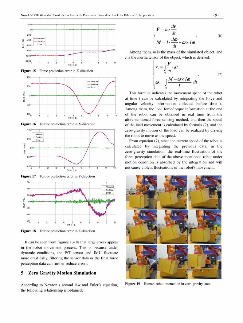
For the error data in Figure 13-18, the maximum error
and the root mean square(RMS) error of each component
were calculated to evaluate the prediction error, as shown
in Table 5. The results show that the maximum error of
force perception is 39.8N, and the maximum root mean
square error is 9.3N; the maximum error of torque
perception is 18.7Nm, and the maximum root mean square
error is 4.4Nm. Table 5 also lists the maximum value of the
measured data of each component as a reference to
illustrate the value range of each component corresponding
to the obtained perceptual error, so as to evaluate the effect
of the model prediction.
Table 5 Error statistics for dynamic force perception
Attribute Fx
/(N)
Fy
/(N)
Fz
/(N)
Tx
/(Nm)
Ty
/(Nm)
Tz
/(Nm)
Max error 24.2 39.8 21.6 18.7 15.5 12.3
Max MSE 6.9 9.3 5.7 4.4 3.6 2.8
Max value 979.6 973.2 1009.0 396.2 354.4 47.8
Figure 13 Force prediction error in X-direction
Figure 14 Force prediction error in Y-direction
58
60
62
64
66
68
70
72
74
76
78
6 7 8 9 10 11 12
Mea
n sq
uare
err
or
Number of hidden layer nodes
0 1 2 3 4 5 6 7 8 9 10-1000
-500
0
500
1000
时间(s)
FeX(
N)
实测值预测值误差
Time
Measured
Prediction
Error
0 1 2 3 4 5 6 7 8 9 10-1000
-500
0
500
1000
时间(s)
FeY(
N)
实测值预测值误差
Time
Measured
Prediction
Error
Novel 6-DOF Wearable Exoskeleton Arm with Pneumatic Force-Feedback for Bilateral Teleoperation
·9·
Figure 15 Force prediction error in Z-direction
Figure 16 Torque prediction error in X-direction
Figure 17 Torque prediction error in Y-direction
Figure 18 Torque prediction error in Z-direction
It can be seen from figures 13-18 that large errors appear
in the robot movement process. This is because under
dynamic conditions, the F/T sensor and IMU fluctuate
more drastically, filtering the sensor data or the final force
perception data can further reduce errors.
5 Zero Gravity Motion Simulation
According to Newton’s second law and Euler’s equation, the following relationship is obtained:
dm
dt
dI I
dt
vF
M
, (6)
Among them, m is the mass of the simulated object, and
I is the inertia tensor of the object, which is derived:
0
0
t
t
t
t
dtm
Idt
I
Fv
M
, (7)
This formula indicates the movement speed of the robot
at time t can be calculated by integrating the force and
angular velocity information collected before time t.
Among them, the load force/torque information at the end
of the robot can be obtained in real time from the
aforementioned force sensing method, and then the speed
of the load movement is calculated by formula (7), and the
zero-gravity motion of the load can be realized by driving
the robot to move as the speed.
From equation (7), since the current speed of the robot is
calculated by integrating the previous data, in the
zero-gravity simulation, the real-time fluctuation of the
force perception data of the above-mentioned robot under
motion condition is absorbed by the integration and will
not cause violent fluctuations of the robot's movement.
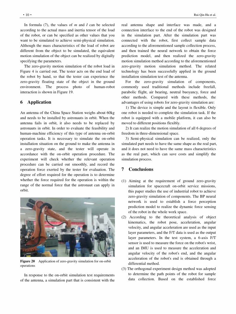
Figure 19 Human-robot interaction in zero-gravity state
0 1 2 3 4 5 6 7 8 9 10-1200
-1000
-800
-600
-400
-200
0
200
时间(s)
Fe
Z(
N)
实测值预测值误差
Time
Measured
Prediction
Error
0 1 2 3 4 5 6 7 8 9 10-400
-200
0
200
400
时间(s)
Me
X(
Nm)
实测值预测值误差
Time
Measured
Prediction
Error
0 1 2 3 4 5 6 7 8 9 10-400
-200
0
200
400
时间(s)
Me
Y(
Nm)
实测值预测值误差
Time
Measured
Prediction
Error
0 1 2 3 4 5 6 7 8 9 10-60
-40
-20
0
20
40
60
时间(s)
Me
Z(
Nm)
实测值预测值误差
Time
Measured
Prediction
Error
Rui-Qin Hu et al.
·10·
In formula (7), the values of m and I can be selected
according to the actual mass and inertia tensor of the load
of the robot, or can be specified as other values that you
want to be simulated to achieve semi-physical simulation.
Although the mass characteristics of the load of robot are
different from the object to be simulated, the equivalent
motion simulation of the object can be realized by digitally
specifying the parameters.
The zero-gravity motion simulation of the robot load in
Figure 4 is carried out. The tester acts on the end load of
the robot by hand, so that the tester can experience the
zero-gravity floating state of the object in the ground
environment. The process photo of human-robot
interaction is shown in Figure 19.
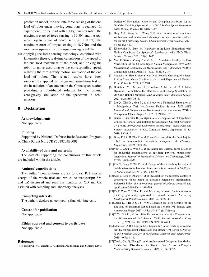
6 Application
An antenna of the China Space Station weighs about 60kg
and needs to be installed by astronauts in orbit. When the
antenna fails in orbit, it also needs to be replaced by
astronauts in orbit. In order to evaluate the feasibility and
human-machine efficiency of this type of antenna on-orbit
operation tasks. It is necessary to simulate the on-orbit
installation situation on the ground to make the antenna in
a zero-gravity state, and the tester will operate in
accordance with the on-orbit operation procedure. The
experiment will check whether the relevant operation
procedure can be carried out smoothly, and record the
operation force exerted by the tester for evaluation. The
degree of effort required for the operation is to determine
whether the force required for the operation is within the
range of the normal force that the astronaut can apply in
orbit.
Figure 20 Application of zero-gravity simulation for on-orbit
operations
In response to the on-orbit simulation test requirements
of the antenna, a simulation part that is consistent with the
real antenna shape and interface was made, and a
connection interface to the end of the robot was designed
in the simulation part. After the simulation part was
connected with the robot, first collect sample data
according to the aforementioned sample collection process,
and then trained the neural network to obtain the force
prediction model, and then realized the zero-gravity
motion simulation method according to the aforementioned
zero-gravity motion simulation method. The related
technology has been successfully applied in the ground
installation simulation test of the antenna.
For the zero-gravity simulation of components,
commonly used traditional methods include freefall,
parabolic flight, air bearing, neutral buoyancy, force and
other methods. Compared with these methods, the
advantages of using robots for zero-gravity simulation are:
1) The device is simple and the layout is flexible. Only
one robot is needed to complete the simulation task. If the
robot is equipped with a mobile platform, it can also be
moved to different positions flexibly.
2) It can realize the motion simulation of all 6 degrees of
freedom in three-dimensional space.
3) Semi-physical simulation can be realized, only the
simulated part needs to have the same shape as the real part,
and it does not need to have the same mass characteristics
as the real part, which can save costs and simplify the
simulation process.
7 Conclusions
(1) Aiming at the requirement of ground zero-gravity
simulation for spacecraft on-orbit service missions,
this paper studies the use of industrial robot to achieve
zero-gravity simulation of components. The BP neural
network is used to establish a force perception
prediction model to realize the dynamic force sensing
of the robot in the whole work space.
(2) According to the theoretical analysis of object
kinematics, the robot pose, acceleration, angular
velocity, and angular acceleration are used as the input
layer parameters, and the F/T data is used as the output
layer parameters. In the test system, a 6-axis F/T
sensor is used to measure the force on the robot's wrist,
and an IMU is used to measure the acceleration and
angular velocity of the robot's end, and the angular
acceleration of the robot's end is obtained through a
differential method.
(3) The orthogonal experiment design method was adopted
to determine the path points of the robot for sample
data collection. Based on the established force
Novel 6-DOF Wearable Exoskeleton Arm with Pneumatic Force-Feedback for Bilateral Teleoperation
·11·
prediction model, the accurate force sensing of the end
load of robot under moving conditions is realized. In
experiment, for the load with 100kg mass on robot, the
maximum error of force sensing is 39.8N, and the root
mean square error of force sensing is 9.3N; The
maximum error of torque sensing is 18.7Nm, and the
root mean square error of torque sensing is 4.4Nm.
(4) Applying the force sensing technology, combined with
kinematics theory, real-time calculation of the speed of
the end load movement of the robot, and driving the
robot to move according to the corresponding speed,
realizing the zero-gravity motion simulation of the end
load of robot. The related results have been
successfully applied in the ground simulation test of
the installation of an antenna in the China space station,
providing a robot-based solution for the ground
zero-gravity simulation of the spacecraft in orbit
mission.
8 Declaration
Acknowledgements
Not applicable.
Funding
Supported by National Defense Basic Research Program
of China (Grant No. JCKY2018203B009)
Availability of data and materials
The datasets supporting the conclusions of this article
are included within the article.
Authors’ contributions
The author’ contributions are as follows: RH was in
charge of the whole trial and wrote the manuscript; SM
and LZ discussed and read the manuscript; QD and CZ
assisted with sampling and laboratory analyses.
Competing interests
The authors declare no competing financial interests.
Consent for publication
Not applicable
Ethics approval and consent to participate
Not applicable
References
[1] Easdown W, Felicetti L. A Mission Architecture and Systems Level
Design of Navigation, Robotics and Grappling Hardware for an
On-Orbit Servicing Spacecraft. UKSEDS Student Space Symposium
2020, Online, October 10, 2020: 1–12.
[2] Ding X L, Wang Y C, Wang Y B, et al. A review of structures,
verification, and calibration technologies of space robotic systems
for on-orbit servicing. Science China Technological Sciences, 2021,
64(3): 462–480.
[3] Klionovska K, Burri M. Hardware-in-the-Loop Simulations with
Umbra Conditions for Spacecraft Rendezvous with PMD Visual
Sensors. Sensors, 2021, 21(4): 1455.
[4] Mou F, Xiao X, Zhang T, et al. A HIL Simulation Facility for Task
Verification of the Chinese Space Station Manipulator. 2018 IEEE
International Conference on Mechatronics and Automation (ICMA),
Changchun, China, August 5– 8, 2018: 2138-2144.
[5] Mavrakis N, Hao Z, Gao Y. On-Orbit Robotic Grasping of a Spent
Rocket Stage: Grasp Stability Analysis and Experimental Results.
Front Robot AI. 2021, 8:652681.
[6] Destefano M , Mishra H , Giordano A M , et al. A Relative
Dynamics Formulation for Hardware- in-the-Loop Simulation of
On-Orbit Robotic Missions. IEEE Robotics and Automation Letters,
2021, 6(2):3569–3576.
[7] Liu Q , Xiao X , Mou F , et al. Study on a Numerical Simulation of
a Manipulator Task Verification Facility System. 2018 IEEE
International Conference on Mechatronics and Automation (ICMA),
Changchun, China, August 5– 8, 2018: 2132-2137.
[8] García J, Gonzalez D, Rodríguez A, et al. Application of Impedance
Control in Robotic Manipulators for Spacecraft On-orbit Servicing.
24th IEEE International Conference on Emerging Technologies and
Factory Automation (ETFA). Zaragoza, Spain, September 10–13,
2019: 836–842.
[9] Dong K, Liu H, Zhu X, et al. Force-free control for the flexible-joint
robot in human-robot interaction. Computers & Electrical
Engineering, 2019, 73: 9–22.
[10] Yao B, Zhou Z, Wang L, et al. Sensor-less external force detection
for industrial manipulators to facilitate physical human-robot
interaction. Journal of Mechanical Science and Technology, 2018,
32(10): 4909–4923.
[11] Ren T, Dong Y, Wu D, et al. Design of direct teaching behavior of
collaborative robot based on force interaction. Journal of Intelligent
& Robotic Systems, 2019, 96(1): 83–93.
[12] Xiao J, Zeng F, Zhang Q, et al. Research on the forcefree control of
cooperative robots based on dynamic parameters identification.
Industrial Robot: the international journal of robotics research and
application, 2019,46(4): 499–509.
[13] Tu X, Zhou Y F, Zhao P, et al. Modeling the static friction in a robot
joint by genetically optimized BP neural network. Journal of
Intelligent & Robotic Systems, 2019, 94(1): 29–41.
[14] Zhang L J , Hu R Q , Yi W M . Research on Force Sensing for the
End-load of Industrial Robot Based on a 6-axis F/T Sensor. Acta
Automatica Sinica, 2017, 43(3):439–447. (in Chinese)
[15] Y Yu, Shi R , Y Lou. Bias Estimation and Gravity Compensation
for Wrist-mounted F/T Sensor. IEEE Sensors Journal ( Early
Access ), 2021, doi: 10.1109/JSEN.2021.3056943.
[16] Almusawi A R J, Dulger L C, Kapucu S. Online teaching of robotic
arm by human–robot interaction: end effector F/T sensing. Journal
of the Brazilian Society of Mechanical Sciences and Engineering,
2018, 40(9): 1–14.
[17] Yao L, Gao Q, Zhang D, et al. An Integrated Compensation Method
for the Force Disturbance of a Six-Axis Force Sensor in Complex
Manufacturing Scenarios. Sensors, 2021, 21(14): 4706.
Rui-Qin Hu et al.
·12·
[18] Su H, Yang C, Mdeihly H, et al. Neural network enhanced robot
tool identification and calibration for bilateral teleoperation. IEEE
Access, 2019, 7: 122041–122051.
[19] Kim Y B, Seok D Y, Lee S Y, et al. 6-Axis F/T Sensor With a
Novel Autonomous Weight Compensating Capability for Robotic
Applications. IEEE Robotics and Automation Letters, 2020, 5(4):
6686–6693.
[20] Lin Z C , Xin W , Yang J , et al. Dynamic trajectory-tracking
control method of robotic transcranial magnetic stimulation with
end-effector gravity compensation based on force sensors. Industrial
Robot, 2018, 45(6):722–731.
[21] El Dine K M, Sanchez J, Corrales J A, et al. Force-torque sensor
disturbance observer using deep learning. International Symposium
on Experimental Robotics, Buenos Aires, Argentina, November 5–8,
2018: 364–373.
Biographical notes
Rui-Qin Hu, born in 1988, is currently an engineer at
Beijing Institute of Spacecraft Environment Engineering,
China. He received his master degree from Tsinghua
University, China, in 2013. His research interests include
spacecraft integretion and test, intelligent robotics and
machine learning.
E-mail: [email protected]
Shao-Huan Meng, born in 1985, is currently an engineer
at Beijing Institute of Spacecraft Environment Engineering,
China. He received his PhD degree from Beihang
University, China, in 2015.
Li-Jian Zhang, born in 1983, is currently an engineer at
Beijing Institute of Spacecraft Environment Engineering,
China. He received his master degree from Harbin
Institute of Technology, China, in 2007.
Que Dong, born in 1983, is currently an engineer at
Beijing Institute of Spacecraft Environment Engineering,
China. He received his PhD degree from Beijing Institute
of Technology, China, in 2015.
Cheng-Li Zhang, born in 1982, is currently an an engineer
at Beijing Institute of Spacecraft Environment Engineering,
China. He received his master degree from Harbin
Institute of Technology, China, in 2008.
Appendix Not applicable