Embed Size (px)
Citation preview

Korpi et al.
RESEARCH
Nonlinear Self-Interference Cancellation in MIMOFull-Duplex Transceivers under CrosstalkDani Korpi*, Lauri Anttila and Mikko Valkama
AbstractThis paper presents a novel digital
self-interference canceller for an inbandmultiple-input-multiple-output (MIMO) full-duplexradio. The signal model utilized by the canceller iscapable of modeling the in-phase quadrature (IQ)imbalance, the nonlinearity of the transmitter poweramplifier, and the crosstalk between thetransmitters, thereby being the most comprehensivesignal model presented thus far within thefull-duplex literature. Furthermore, it is also shownto be valid for various different radio frequency (RF)cancellation solutions. In addition to this, a novelcomplexity reduction scheme for the digital cancelleris also presented. It is based on the widely knownprincipal component analysis, which is used togenerate a transformation matrix for controlling thenumber of parameters in the canceller. Extensivewaveform simulations are then carried out, and theobtained results confirm the high performance ofthe proposed digital canceller under various circuitimperfections. The complexity reduction scheme isalso shown to be capable of removing up to 65 % ofthe parameters in the digital canceller, therebysignificantly reducing its computationalrequirements.Keywords: Full-duplex; MIMO; self-interference;RF impairments; crosstalk
1 IntroductionInband full-duplex communications is a promising can-didate technology for further improving the spectralefficiency of the next generation wireless systems, suchas the 5G networks [1–11]. The basic idea behind it isto transmit and receive at the same time at the samecenter-frequency, thereby in principle doubling the spec-tral efficiency. The drawback of such inband full-duplex*Correspondence: [email protected] of Electronics and Communications Engineering, TampereUniversity of Technology, Tampere, FinlandFull list of author information is available at the end of the article
operation is the own transmit signal, which is couplingto the receiver and becomes an extremely powerfulsource of self-interference (SI). The most significantchallenge in implementing inband full-duplex radios inpractice is thereby the development of SI cancellationsolutions, which are capable of removing the SI in thereceiver. There are already reports of various demon-strator implementations, which achieve relatively highSI cancellation performance, thereby allowing for trueinband full-duplex operation [1–3,6, 7, 11–14].
Moreover, in order to meet the high throughput re-quirements of the future wireless networks, it is in-evitable that the inband full-duplex concept must becombined with MIMO capabilities in the transceiv-ers [7,12–19]. This obviously results in a higher physicallayer capacity, but it also requires more elaborate SIcancellation solutions. In particular, in a MIMO trans-ceiver, the observed SI signal in each receiver consists ofa combination of all the transmit signals, which meansthat also the SI cancellers must have all of the trans-mit signals available. Furthermore, in order to performSI cancellation, the coupling channels between all thetransmitters and receivers must be estimated, whichresults in a somewhat more demanding SI cancellationprocedure. Nevertheless, this increased complexity isjustified by the higher physical layer throughputs.
Especially the complexity of the RF canceller is heav-ily affected by the number of transmitters and re-ceivers [7,15]. For an NT ×NR MIMO transceiver, theRF canceller requires at least NTNR cancellation paths,or even more if using a multi-tap solution [7, 20]. Thisnumber can be somewhat decreased by using auxiliarytransmitters to upconvert digitally generated cancel-lation signals, since then only NR cancellation pathsare required. However, the drawback of this solution isobviously the need for additional RF transmitters, aswell as the fact that the digitally generated cancellationsignals do not include any of the transmitter-inducedimpairments, which thereby remain unaffected by thistype of an RF cancellation solution [1]. Another possiblesolution for decreasing the complexity of RF cancel-lation in the context of very large transmit antennaarrays is to use beamforming to form nulls in the receiveantennas [4,21], which might even allow for completelyomitting RF cancellation. In typical MIMO devices,

Korpi et al. Page 2 of 16
Linear crosstalk Nonlinear crosstalk
PA
PA
PA
Figure 1 An illustration of the crosstalk phenomenon in athree-antenna MIMO transmitter, where crosstalk occurs bothbefore and after the PAs. The former is typically referred to asnonlinear crosstalk, while the latter is called linear crosstalk.
however, the increase in the RF cancellation complexityis more or less inevitable.
Also the complexity of digital SI cancellation is some-what increased under MIMO operation, but it is ob-viously more straight-forward to process several SIsignals in the digital domain. In particular, more com-putational resources are needed to estimate all thechannel responses between the several transmitters andreceivers, but no additional RF hardware is required.However, having several transmit chains on a single chipintroduces another issue from the perspective of thedigital canceller: the crosstalk between the transmitters,which occurs both before and after the power ampli-fiers (PAs) [22–28]. This phenomenon is illustrated inFig. 1 for an example case of three transmitters. Whatmakes this an especially cumbersome issue is the factthat typically the PAs introduce significant nonlineardistortion [3, 29]. This, on the other hand, means thatnonlinear modeling of the SI is required in the digitalcanceller, which is very challenging if the PA input isin fact a linear combination of all the original transmitsignals, as is the case under crosstalk [26]. Neverthe-less, it is still necessary to model the crosstalk, sinceotherwise the accuracy of the regenerated SI signalis not sufficiently high. This is especially crucial forthe emerging massive MIMO transceivers, where thelarge amount of transmit chains calls for a high level ofintegration, which results in more leakage between thetransmission paths [28]. Hence, the increase in compu-tational complexity caused by the crosstalk modelingmust be tolerated in order to obtain sufficient levels ofSI cancellation also under MIMO operation.
In this article, we present a general signal model forthe observed SI in the digital domain under a scenariowhere there is crosstalk between the transmit chains be-fore and after nonlinear PAs. Moreover, it is shown that
the signal model can be applied to various different RFcancellation solutions. The presented comprehensivesignal model, which shows the effect of the crosstalk interms of the original transmit signals, is then used asa basis for a high-performance digital SI canceller. TheIQ imbalance occurring both in the transmitters andin the receivers is also included in the signal model,since it is typically one of the dominant sources of dis-tortion in a practical transceiver, alongside with thePA-induced nonlinearities [30].
Furthermore, to address the increase in the compu-tational complexity due to the MIMO operation andcrosstalk modeling, a novel principal component anal-ysis (PCA) based solution is proposed, which can beused to control the complexity of the signal model.In particular, PCA processing is used to identify theinsignificant terms in the observed SI signal, whichare then omitted in the further cancellation processing.This results in a significant reduction of the unknownparameters that must be estimated, which obviouslydecreases the computational requirements of the dig-ital SI canceller. Moreover, since the most dominantSI terms are retained by such processing, there is noessential degradation in the cancellation performance.To the best of our knowledge, such complexity reduc-tion schemes have not been previously proposed in thecontext of SI cancellation solutions.
The detailed list of novel contributions in this paperis as follows:• We derive the most comprehensive MIMO signal
model for the observed SI presented so far in theliterature. It covers various RF cancellation sce-narios, while also modeling the crosstalk betweenthe transmitters under low-cost nonlinear PAs andIQ imbalance.
• We propose a novel nonlinear digital SI canceller,which utilizes the aforementioned advanced signalmodel.
• We propose a novel complexity reduction schemebased on PCA, which can be used to control thecomputational complexity of the digital canceller,while minimizing the decrease in the cancellationperformance.
• We present numerical results, which illustrate vari-ous aspects of the proposed digital SI cancellationsolution with realistic waveform simulations.
The rest of this article is organized as follows. InSection 2, the MIMO signal model is derived. Then,in Section 3, the actual nonlinear digital SI cancelleris presented, alongside with the parameter estimationprocedure and the PCA-based complexity reductionscheme. After this, in Section 4, the proposed digital SIcancellation solution is evaluated with realistic wave-form simulations. Finally, the conclusions are drawn inSection 5.
Korpi et al. Page 3 of 16
NR receiver chains
LNA IQ Mixer LPF VGA ADC Digital
cancellation
Σ+
−
NR auxiliary transmitter chains
LPFIQ MixerVGA DAC
Digital
processing
NT transmitter chains
LPFIQ MixerVGAPA DAC
BPFRF can-
cellation
RF can-
cellation
circuitry
Self-in
terf
ere
nce
co
uplin
g c
han
nel
Signals of interest
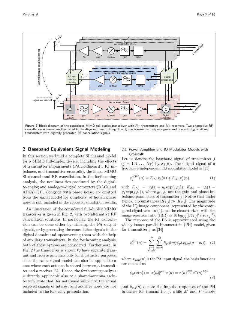
Figure 2 Block diagram of the considered MIMO full-duplex transceiver with NT transmitters and NR receivers. Two alternative RFcancellation schemes are illustrated in the diagram: one utilizing directly the transmitter output signals and one utilizing auxiliarytransmitters with digitally generated RF cancellation signals.
2 Baseband Equivalent Signal ModelingIn this section we build a complete SI channel modelfor a MIMO full-duplex device, including the effectsof transmitter impairments (PA nonlinearity, IQ im-balance, and transmitter crosstalk), the linear MIMOSI channel, and RF cancellation. In the forthcominganalysis, the nonlinearities produced by the digital-to-analog and analog-to-digital converters (DACs andADCs) [31], alongside with phase noise, are omittedfrom the signal model for simplicity, although phasenoise is still included in the reported simulation results.
An illustration of the considered full-duplex MIMOtransceiver is given in Fig. 2, with two alternative RFcancellation solutions. In particular, the RF cancella-tion can be done either by utilizing the PA outputsignals, or by generating the cancellation signals in thedigital domain and upconverting them with the helpof auxiliary transmitters. In the forthcoming analysis,both of these options are considered. Furthermore, inFig. 2 the transceiver is shown to have separate trans-mit and receive antennas only for illustrative purposes,since the same signal model can also be applied to acase where each antenna is shared between a transmit-ter and a receiver [32]. Hence, the forthcoming analysisis directly applicable also to a shared-antenna archi-tecture. Note that, for notational simplicity, the actualreceived signals of interest and additive noise are notincluded in the following presentation.
2.1 Power Amplifier and IQ Modulator Models withCrosstalk
Let us denote the baseband signal of transmitter j(j = 1, 2, . . . , NT ) by xj(n). The output signal of afrequency-independent IQ modulator model is [33]
xIQMj (n) = K1 ,jxj(n) +K2 ,jx
∗j (n) (1)
with K1 ,j = 1/2(1 + gj exp(jϕj)), K2 ,j = 1/2(1 −gj exp(jϕj)), where gj , ϕj are the gain and phase im-balance parameters of transmitter j. Notice that undertypical circumstances |K1 ,j | � |K2 ,j |. The magnitudeof the IQ image component, represented by the conju-gated signal term in (1), can be characterized with theimage rejection ratio (IRR) as 10 log10(|K1 ,j |2/|K2 ,j |2).
The response of the PA is approximated using thewidely known parallel Hammerstein (PH) model, givenfor transmitter j as [34]
xP Aj (n) =
P∑p=1
p odd
M∑m=0
hp,j(m)ψp(xj,in(n−m)), (2)
where xj,in(n) is the PA input signal, the basis functionsare defined as
ψp(x(n)) = |x(n)|p−1x(n) = x(n)p+1
2 x∗(n)p−1
2
(3)
and hp,j(n) denote the impulse responses of the PHbranches for transmitter j, while M and P denote

Korpi et al. Page 4 of 16
the memory depth and nonlinearity order of the PHmodel, respectively [34–36]. The PH nonlinearity is awidely used nonlinear model for direct as well as inversemodeling of PAs [34–37].
Due to the crosstalk occurring before each PA, re-ferred to as nonlinear crosstalk, the input signal xj,in(n)can be written as
xj,in(n) =NT∑i=1
αijxIQMi (n), (4)
where αij is the crosstalk coefficient between the ithand jth transmitter chains, and αjj = 1 ∀ j. In otherwords, as a result of the crosstalk occurring before thePAs, each PA input signal is in fact a linear combina-tion of all the different transmit signals. The crosstalkphenomenon is illustrated for an example case of threetransmitters in Fig. 1, where both the nonlinear andlinear crosstalk are shown. Inserting now (1) into (4),we can rewrite the PA input signal as
xj,in(n) =NT∑i=1
αij (K1 ,ixi(n) +K2 ,ix∗i (n))
=NT∑i=1
α1 ,ijxi(n) +NT∑i=1
α2 ,ijx∗i (n), (5)
where α1 ,ij = αijK1 ,i and α2 ,ij = αijK2 ,i .Using (5), the signal at the PA output can be written
as shown in (6). It can be further modified by expandingall the integer powers of the sum signals as shown in theAppendix, which gives (7), where hp,j,q0,... ,rNT−1(m)are the coefficients for the basis function of the form∏NT
i=1 xi(n)aix∗i (n)bi such that∑NT
i=1 (ai + bi) = p. Thissignal model is of similar form as the one presentedin [26], with the exception that the model in (7) alsoincorporates the effect of IQ imbalance and is thusmore complete.
In order to simplify (7), it can be noted that, for thejth transmit signal and the pth nonlinearity order, thesignal model contains in fact all the different combina-tions of the exponents qm and rn, under the constraintthat their sum is equal to p. This means that we canrewrite (7) as
xPAj (n) =
P∑p=1
p odd
∑k
‖sk‖1=p
M∑m=0
hj,p,sk (m)
×NT∏q=1
xq(n−m)skqx∗q(n−m)sk
q+NT , (8)
where sk is the kth combination of the 2Nt × 1 expo-nent vector s, hj,p,sk (m) contains the corresponding
coefficients, and ‖·‖1 denotes the L1-norm. Note thatall the elements of s are non-negative integers, as perthe signal model. To illustrate its structure, all thevariations of s for NT = 1 and P = 3 are writtenbelow:
s1 =[1 0
]T , s2 =[0 1
]T , s3 =[1 2
]Ts4 =
[2 1
]T , s5 =[3 0
]T , s6 =[0 3
]TAfter the PAs, there is typically also some additional
crosstalk between the transmitters, referred to as linearcrosstalk. Taking also this phenomenon into account,the final output signal for the jth transmitter can bewritten as
xTXj (n) =
NT∑l=1
βljxPAl (n)
=P∑
p=1p odd
∑k
‖sk‖1=p
M∑m=0
NT∑l=1
βljhl,p,sk (m)
×NT∏q=1
xq(n−m)skqx∗q(n−m)sk
q+NT , (9)
where βlj is the crosstalk coefficient between the lth andjth transmitters. It can be observed that the essentialsignal model remains the same as in (8), but withmodified coefficients written as
hj,p,sk (m) =NT∑l=1
βljhl,p,sk (m). (10)
Denoting the MIMO propagation channel impulseresponse from TX antenna j to RX antenna i bycij(l), l = 0, 1, . . . , L, the received SI signal at RXantenna i (i = 1, 2, . . . , NR) can now be written as
zi(n) =NT∑j=1
L∑l=0
cij(l)xTXj (n− l)
=P∑
p=1p odd
∑k
‖sk‖1=p
NT∑j=1
L∑l=0
M∑m=0
cij(l)hj,p,sk (m)
×NT∏q=1
xq(n−m− l)skqx∗q(n−m− l)sk
q+NT

Korpi et al. Page 5 of 16
xPAj (n) =
P∑p=1
p odd
M∑m=0
hp,j(m)xj,in(n−m)p+1
2 x∗j,in(n−m)p−1
2
=P∑
p=1p odd
M∑m=0
hp,j(m)
p+12∑
k0=0
(p+12k0
)(NT∑i=1
α1,ijxi(n−m)) p+1
2 −k0 (NT∑i=1
α2,ijx∗i (n−m)
)k0
×
p−12∑
l0=0
(p−12l0
)(NT∑i=1
α∗2,ijxi(n−m)) p−1
2 −l0 (NT∑i=1
α∗1,ijx∗i (n−m)
)l0
(6)
xPAj (n) =
P∑p=1
p odd
p∑q0=0
p−q0∑q1=0· · ·
p−q0−···−qNT−2∑qNT−1=0
q0∑r1=0
q0−r1∑r2=0
· · ·q0−r1−···−rNT−2∑
rNT−1=0
M∑m=0
hp,j,q0,... ,rNT−1(m)
× x1(n−m)q1x2(n−m)q2 · · ·xNT(n−m)p−
∑NT−1i=0
qi
× x∗1(n−m)r1x∗2(n−m)r2 · · ·x∗NT(n−m)q0−
∑NT−1i=1
ri (7)
=P∑
p=1p odd
∑k
‖sk‖1=p
M+L∑m=0
hi,p,sk (m)
×NT∏q=1
xq(n−m)skqx∗q(n−m)sk
q+NT . (11)
Again, the signal model still remains the same as in(8), but with slightly modified coefficients, which areobtained from
hi,p,sk (m) =NT∑j=1
m∑l=0
cij(l)hj,p,sk (m− l).
The new memory length of the received signal model isalso increased from M to M + L. The input signal ofthe ith receiver (zi(n)) is then further processed by theRF canceller and the actual receiver chain. Note thatthe above signal model in (11) also applies to circulatorand electrical balance duplexer based implementations,where each transmitter and receiver pair share the sameantenna [32], and hence it is generic in that respect.
2.2 RF CancellationTo ensure an extensive analysis and derivation for theproposed digital cancellation algorithm, we considerthree different RF cancellation solutions. The first tech-nique is similar to what has been used, e.g, in [5, 6],
and it involves directly tapping the transmitter out-puts to obtain the reference signals for RF cancellation.This method is based on purely analog processing, asthe whole cancellation procedure is performed in theRF domain. The two other considered methods arebased on auxiliary TX chains, which are used to pro-duce the RF cancellation signal from digital basebandsamples [1, 38,39]. We call this latter approach hybridRF cancellation to distinguish it from purely analogcancellation. Furthermore, we consider both linear andnonlinear preprocessing to be used with this auxiliarytransmitter based RF cancellation.
2.2.1 RF Cancellation with Transmitter OutputSignals
In this RF cancellation method, the output of eachTX chain is tapped, and subtracted from each of thereceived signals after suitable gain, phase and delay ad-justments. These RF cancellers can be either single-tapor multi-tap [9,40], for which reason we denote themwith impulse responses hRF
ij (l), operating on the TXoutput signals xTX
j (n). The coefficients are obviouslychosen such that they model the MIMO coupling chan-nel coefficients in cij(n) as accurately as possible. TheRF cancellation signal for the ith receiver can thus be

Korpi et al. Page 6 of 16
written as
zci (n) =
NT∑j=1
L′∑l=0
hRFij (l)xTX
j (n− l), (12)
where L′ is the number of taps in the RF canceller. Itcan be easily shown, that the cancellation signal is ofsimilar form as the actual received signal in (11), withcoefficients of the form
hRFi,p,sk (m) =
NT∑j=1
m∑l=0
hRFij (l)hj,p,sk (m− l)
and a memory length of M + L′. Thus, the receivedSI signal of receiver i, after this type of analog RFcancellation, becomes
ri(n) = zi(n)− zci (n)
=P∑
p=1p odd
∑k
‖sk‖1=p
M+max(L,L′)∑m=0
(hi,p,sk (m)
−hRFi,p,sk (m)
) NT∏q=1
xq(n−m)skqx∗q(n−m)sk
q+NT ,
(13)
Hence, the structure of the RF canceller output sig-nal model is still of the same form as in (11), butwith modified coefficients expressed as hi,p,sk (m) =hi,p,sk (m)− hRF
i,p,sk (m).This type of purely analog RF cancellation calls for
NT ×NR canceller circuits to be implemented in thedevice, one canceller from each transmitter to eachreceiver. The complexity may become prohibitive whenthe number of antennas is significantly increased and,thereby, when implementing a high order full-duplexMIMO device, alternative methods for RF cancellationmight have to be considered.
2.2.2 Hybrid RF Cancellation Using AuxiliaryTransmitters with Linear Preprocessing
One such alternative RF canceller structure is the hy-brid method, which utilizes extra transmitter chains,one for each receiver, to upconvert and subtract esti-mated replicas of the SI signals from the received signalsat RF [1,38,39]. In this case, linear MIMO filtering is al-ready done at digital baseband on the transmit signalsxj(n) with some estimated MIMO channel responseshRF
ij (l). Since the transmit signals from the differentantennas can now be combined already in the digitaldomain, the analog hardware complexity of this type
of an RF cancellation scheme scales with NR insteadof NTNR, and may prove to be more attractive with ahigh number of antennas. Note that in this subsectionwe consider only linear processing for the hybrid RFcanceller, and thereby IQ modulator imbalance or PAnonlinearity are not explicitly dealt with at this stage.The RF cancellation signal can in this case be writtenas
zci (n) =
NT∑j=1
L′∑l=0
hRFij (l)xj(n− l), (14)
which is a special case of the signal model in (11) withP = 1 and coefficients hRF
i,1,sk (m) consisting of hRFij (l)
with proper sk. The signal after RF cancellation isagain obtained as shown in (13), and with the finalcoefficients as
hi,p,sk (m) = hi,p,sk (m)− hRFi,p,sk (m), p = 1
hi,p,sk (m) = hi,p,sk (m), p ≥ 3
Also this model is essentially of the same form as (11),with the coefficients of the linear SI terms being affectedby the hybrid RF cancellation procedure, while theother terms remain unchanged. This means that theobserved SI signal in the receiver digital domain canstill be modeled with the same signal model as inthe case of pure analog RF cancellation (or no RFcancellation at all). Thus, from the perspective of thedigital cancellation algorithm, it makes no differencewhether RF cancellation is performed by tapping thetransmitter output or by using auxiliary TX chainswith linear preprocessing, although the RF cancellationperformance itself might obviously be different for theconsidered methods.
2.2.3 Hybrid RF Cancellation Using AuxiliaryTransmitters with Nonlinear Preprocessing
Yet another alternative RF cancellation technique uti-lizes auxiliary transmitters, but with nonlinear pre-processing, instead of purely linear processing. Theestimated MIMO channel responses of the differentnonlinear SI terms are now denoted by hRF
ij,p(l). In theforthcoming analysis it is assumed that the auxiliaryTX chains are linear. This is a relatively feasible as-sumption, since no PA is required due to the loweroutput power requirements. Now, the cancellation sig-nal obtained with this RF cancellation procedure can

Korpi et al. Page 7 of 16
be expressed as
zci (n) =
NT∑j=1
P ′∑p=1
p odd
L′∑l=0
hRFij,p(l)xj(n− l)
p+12
×x∗j (n− l)p−1
2 , (15)
where P ′ is the nonlinearity order of the RF cancella-tion signals. Note that this signal model neglects IQimbalance and crosstalk, since the RF canceller mustonly attenuate the SI such that the receiver is not sat-urated. Also this RF cancellation signal can be easilyrepresented with a signal model of the same form as in(11). The coefficients hRF
i,p,sk (m) of the signal model nowconsist of hRF
ij,p(l) with the parameters p and sk that cor-respond to the basis functions xj(n− l)
p+12 x∗j (n− l)
p−12 ,
and other coefficients are set to zero. Similar to theother RF cancellation schemes, after subtracting thecancellation signal from the received signal, as in (13),the signal model remains the same and its coefficientsare hi,p,sk (m) = hi,p,sk (m)−hRF
i,p,sk (m). Now, also someof the nonlinear SI terms are attenuated by RF can-cellation, as they are modeled in the preprocessingstage.
Overall, it can be concluded that the essential struc-ture of the observed SI signal in the digital domain isindependent of the chosen method for RF cancellation.This means that, in the forthcoming analysis, the samedigital cancellation algorithm can be applied in all thesituations since the only difference between the threealternative RF cancellation schemes are the relativepower levels of the various SI terms. However, as al-ready mentioned, the RF cancellation performance islikely to differ between these techniques, and also thehardware and computational requirements are differentfor each RF canceller structure.
In the forthcoming analysis, we will refer to the pa-rameters of the signal model in all cases by hi,p,sk (m),similar to the above derivations, even though the exactvalues of the different coefficients vary for different RFcancellation techniques. This notation will simplify theequations and make them more straightforward andillustrative. Hence, the signal after RF cancellation,which is then processed by the digital canceller, can bewritten as
ri(n) =P∑
p=1p odd
∑k
‖sk‖1=p
M+max(L,L′)∑m=0
hi,p,sk (m)
×NT∏q=1
xq(n−m)skqx∗q(n−m)sk
q+NT , (16)
Note that this signal model implicitly incorporates alsothe IQ imbalance occurring in the receiver, even thoughit is omitted in the derivations for brevity [15].
2.3 Total Number of Basis Functions in the OverallModel
In general, with the above cascaded modeling approachfor IQ modulator and PA impairments with crosstalkbetween the transmitters, it can easily be shown thatthe total number of basis functions in (16) becomes
nb =P∑
p=1p odd
(p+ 2NT − 1
2NT − 1
). (17)
Figure 3 illustrates the number of basis functions fordifferent nonlinearity orders and numbers of trans-mit antennas for the full signal model and also forthe crosstalk-free signal model discussed below in Sec-tion 2.4. It is immediately obvious that with higherorder MIMO systems, or with heavily nonlinear PAs,the number of basis functions becomes unacceptablyhigh when utilizing the full signal model with crosstalk.Thus, it is necessary to determine methods that willdecrease the number of basis functions, and therebyfacilitate the estimation of the parameters of this signalmodel also in practice.
Luckily, many of the terms arising from the cascadeof the impairments are so insignificant that they can beneglected with very little effect on the overall modelingaccuracy. This will reduce the computational cost ofsuch modeling and the corresponding cancellation pro-cedure. In this work, we propose a specific preprocessingstage which can be used to decrease the dimensionalityof the full signal model in (16). This is elaborated inmore details in Section 3.2.
2.4 Nonlinear Signal Model without CrosstalkAnother simple way to decrease the number of basisfunctions is to neglect the crosstalk effect between thetransmitters. Then, the cross terms between the differ-ent transmit signals will be removed, which obviouslyresults in a significant decrease in the number of un-known parameters. Modifying (16) accordingly, we canwrite the signal model now as
ri(n) =NT∑j=1
P∑p=1
p odd
p∑q=0
M+max(L,L′)∑m=0
hi,j,p,q(m)
×xj(n−m)qx∗j (n−m)p−q, (18)
where hi,j,p,q(m) represents now the coupling channelcorresponding to the considered SI signal terms prop-agating from the jth transmitter to the ith receiver.

Korpi et al. Page 8 of 16
Nonlinearity order3 5 7 9 11 13
Num
ber
ofba
sis
func
tions
0
200
400
600
800
1000
1200
1400
1600
1800
2000
Full signal model, NT
= 6
Crosstalk-free signal model, NT
= 6
NT
= 5
NT
= 4
NT
= 3
NT
= 2
Figure 3 The number of basis functions with respect to thenonlinearity order of the signal model (P ). The curves havebeen plotted for different numbers of transmit antennas and forboth the full signal model and the crosstalk-free signal model.
This signal model is also derived in [15], where it isbriefly discussed and analyzed. For this reason, thedetailed derivation process of (18) is omitted in thisarticle.
Since now all the cross-terms are neglected from thesignal model, the number of basis functions can beexpressed as
nCT−freeb = NT
(P + 1
2
)(P + 1
2 + 1)
. (19)
When investigating Fig. 3, it can be seen that thissignal model results in a significant reduction of ba-sis functions, when compared to the full signal modelwith crosstalk. With moderate crosstalk levels, it istherefore likely that using this signal model will pro-vide a very favorable trade-off between cancellationperformance and computational complexity. However,as already discussed, in highly integrated transceiversexplicit modeling of the crosstalk between the trans-mitters is likely required in order to ensure sufficientcancellation performance [28].
3 Self-Interference Parameter Estimationand Digital Cancellation
In this section, building on the previous modeling in,e.g., [15, 29], we will describe the proposed digital can-cellation algorithm that models both IQ imbalance andPA nonlinearity in a MIMO full-duplex transceiver withcrosstalk between the transmitters. In general, thereare two possible approaches for nonlinear digital SI can-cellation: (i) construct a linear-in-parameters model ofthe observed SI signal in the digital domain, includ-ing the different impairments, the MIMO propagation
MIMO self-
interference
channel and
RF cancellation
Estimated
nonlinear
MIMO channel
and PCA pro-
cessing
Σ
Σ
Σ
r1(n)
r2(n)
rN (n)R
Σ
Σ
Σ
s1(n)
s2(n)
sN (n)R
r1(n)
r2(n)
rN (n)R
{si(n), wi(n)}
Nonlinear
transmitter
Nonlinear
transmitter
Nonlinear
transmitter
x1(n)
x2(n)
xN (n)T
Cro
ssta
lk
Figure 4 A description of the proposed model for regenerationand cancellation of nonlinear self-interference.
channel, and RF cancellation, estimate the unknownparameters of the model, and finally recreate and can-cel the SI from the received signals; (ii) have separatemodels for the MIMO propagation channel and thetransmitter impairments, estimate the unknown modelparameters sequentially, and recreate and cancel the SIfrom the received signals. Typically the latter approachis computationally less demanding, but it requires amore elaborate estimation procedure. In this article,we consider the former approach, while the latter is leftfor future work.
3.1 Linear-in-parameters ModelHaving already derived a linear-in-parameters signalmodel in Section 2, presented in (16), the next stepis to estimate its parameters in hi,p,sk (m). After this,the estimated parameters are used to regenerate the SIsignals, which are then subtracted from the receivedsignals at digital baseband to obtain cancellation. Fig-ure 4 shows the whole digital cancellation procedureon a fundamental level.
Denoting the desired signal of interest and additivenoise at the ith receiver by si(n) and wi(n), respectively,the overall received signal at digital baseband can beexpressed as
yi(n) = ri(n) + si(n) + wi(n). (20)
The corresponding output of the digital SI canceller isthen
si(n) = yi(n)− ri(n), (21)
where ri(n) denotes the SI estimate obtained usingthe signal model in (16) with estimated parameters,

Korpi et al. Page 9 of 16
written as
ri(n) =P∑
p=1p odd
∑k
‖sk‖1=p
M2∑m=−M1
ˆhi,p,sk (m)
×NT∏q=1
xq(n−m)skqx∗q(n−m)sk
q+NT . (22)
Here, P is the nonlinearity order of the digital canceller,M1 is the number of pre-cursor taps, M2 is the numberof post-cursor taps, and ˆ
hi,p,sk (m) contains the esti-mated parameters of the signal model. The pre-cursortaps are introduced to model all the memory effectsproduced by the transmitter and RF cancellation cir-cuitry.
3.1.1 Least Squares Based EstimatorIn this work, the actual parameter learning is performedwith the widely used least squares (LS) estimation. Forbrevity, the parameter learning and digital cancellationprocedure is here outlined only for the ith receiver,since the procedure is identical for all the receivers.
In practice, calculating the LS estimate requiresknowledge of (i) the original transmitted data signal,(ii) the predetermined signal model in (16), and (iii)the observed received signal yi(n). In the consideredMIMO full-duplex device, all of these are obviouslyknown by the digital canceller. Since the LS estimationis performed using a block of data, the vector/matrixrepresentations of the relevant signals with N observedsamples are first defined as
yi = ri + si + wi, with (23)
yi =[yi(n) yi(n+ 1) · · · yi(n+N − 1)
]Tand ri, si, wi are defined in the same manner as yi.The error vector is then defined as
ei = yi − ri (24)
where the nonlinear SI estimate is
ri = Ψˆhi. (25)
Here, Ψ is a horizontal concatenation of the convolutionmatrices shown in (26), where
ψi,p,sk (n) =NT∏q=1
xq(n)skqx∗q(n)sk
q+NT ,
with p = 1, 3, . . . , P , and sk is each combination forwhich
∥∥sk∥∥
1 = p, similar to the sum limits shown
in (16). Overall, the number of concatenated matricesis given by the total number of basis functions in (17),since this is the amount of different combinations of sk
for all the nonlinearity orders.Alternatively, in the crosstalk-free model Ψ consists
of the concatenation of the matrices of the form shownin (27), where ψj,p,q(n) = xj(n)qx∗j (n)p−q, with j =1, 2, . . . , NT , p = 1, 3, . . . , P , and q = 0, 1, . . . , p.
An estimate of the parameter vector hi, denoted byˆhi, is a vertical concatenation of the vectors
ˆhi,p,sk =[ˆhi,p,sk (−M1) · · · ˆ
hi,p,sk (M2)]T
(28)
In the crosstalk-free model, the parameter vector con-sists of the concatenation of vectors
ˆhi,j,p,q =[ˆhi,j,p,q(−M1) · · · ˆ
hi,j,p,q(M2)]T
(29)
The LS estimate of the parameter vector hi is thenfound as the solution which minimizes the power of theerror vector ei, as
ˆhi = arg minhi
‖ei‖2 = arg minhi
∥∥∥yi −Ψhi
∥∥∥2
= (ΨHΨ)−1ΨHyi, (30)
assuming full column rank in Ψ.
3.2 Computationally Efficient Estimation with PrincipalComponent Analysis
Another approach to simplify the estimation proce-dure is to retain the cross-terms, and instead determinewhich of them are actually significant in terms of thecancellation performance. In this analysis, principalcomponent analysis (PCA) [41] is used to decrease thenumber of parameters to be estimated. The idea behindthe PCA is to determine which of the terms have thehighest variance, providing valuable information regard-ing the significance of the different basis functions. Inpractice, PCA results in a transformation matrix, withwhich the original data matrix is multiplied. The size ofthe transformation matrix can be chosen to provide thedesired number of parameters for the final estimationprocedure.
There are also various alternative solutions for modelcomplexity reduction, such as compressed sampling(CS) based techniques. Nevertheless, in this work wechoose to use the PCA since it is a straight-forwardmethod for the complexity reduction of the proposedsignal model, while also providing nearly the same

Korpi et al. Page 10 of 16
Ψi,p,sk =
ψi,p,sk (n+M1) ψi,p,sk (n+M1−1) · · · ψi,p,sk (n−M2)
ψi,p,sk (n+M1+1) ψi,p,sk (n+M1) · · · ψi,p,sk (n−M2+1)...
.... . .
...ψi,p,sk (n+M1+N−1) ψi,p,sk (n+M1+N−2) · · · ψi,p,sk (n−M2+N−1)
(26)
Ψj,p,q =
ψj,p,q(n+M1) ψj,p,q(n+M1 −1) · · · ψj,p,q(n−M2)
ψj,p,q(n+M1 +1) ψj,p,q(n+M1) · · · ψj,p,q(n−M2+1)...
.... . .
...ψj,p,q(n+M1+N−1) ψj,p,q(n+M1+N−2) · · · ψj,p,q(n−M2+N−1)
(27)
performance as CS when high modeling accuracy isrequired [42]. Experimenting with different complexityreduction methods is an important future work itemfor us.
The first step in obtaining the desired PCA transfor-mation matrix is to determine the least squares channelestimate given in (30) using all the basis functions. Thisestimate should be calculated with the highest possibletransmit power, since the nonlinear SI terms that arenegligible with the highest power will also be negligiblewith any lower transmit power. Hence, this reveals theterms, which can be omitted under the whole consideredtransmit power range. If the transceiver in question hasmore than one receiver chain, the channel estimationcan be done individually for all of them, after whichthe mean value of the estimates is calculated. This isdone to avoid having separate transformation matricesfor each receiver, resulting in a decreased amount ofrequired data storage. The hereby obtained coefficientvector, which is denoted by ˆh0, is used as an initialchannel estimate for the full set of basis functions.
The next step is to determine the relative strengthsof the different terms present in the SI signal. Using theinitial channel estimate, this can be done by multiplyingthe original data matrix with the obtained estimate.Then, we get
Ψ0 =(1ˆhT
0
)×Ψ, (31)
where 1 is a column vector consisting of 1s, and ×denotes element-wise multiplication between two ma-trices. The matrix Ψ0 now contains all the SI termsin its columns, each multiplied with the correspondingcoefficient of the initial channel estimate.
As a starting point for the PCA, the singular valuedecomposition of the normalized data matrix can be
expressed as
Ψ0 = UΣVH , (32)
where U and V are the matrices containing the leftand right singular vectors, respectively, while Σ is adiagonal matrix consisting of the corresponding sin-gular values. In this analysis, it is assumed that thesingular values are in decreasing order. To minimizethe possible numerical issues upon the PCA transfor-mation, the actual transformation matrix is obtainedin its normalized form, which is given by
W = VΣ−1. (33)
To control the number of parameters, part of thecolumns of the obtained matrix W can then be omit-ted. Based on the earlier assumption regarding theordering of the singular values, the columns of thetransformation matrix represent the different parame-ters in the descending order of their significance. Thus,by starting to remove the columns from the right, thenumber of parameters can be decreased with minimaleffect on the modeling accuracy. Thus, denoting thenumber of chosen parameters with u, we can write thefinal transformation matrix as
W =[w1 w2 · · · wu
], (34)
where wi is the ith column of the matrix W. Finally,the reduced data matrix can be calculated as
Ψ = ΨW. (35)
The hereby obtained data matrix is then used in theleast squares estimation as a replacement for the origi-nal data matrix Ψ. It should also be noted that when
Korpi et al. Page 11 of 16
generating the actual digital cancellation signal, thecancellation data matrix must be transformed with thesame matrix W, as the SI channel estimate is onlyvalid in this transformed space.
An important aspect to point out is that the trans-formation matrix W is calculated only once with thehighest transmit power, after which it can be used withall transmit powers to reduce the number of basis func-tions. Namely, since the strengths of the nonlinearitiesare directly proportional to the transmit power, the SIterms that are negligibly weak with the highest trans-mit power are at least as weak with the lower transmitpowers, which means that the same SI terms can beomitted also then. This is also proven by the wave-form simulations, the results of which will be discussedin Section 4. However, should the SI channel changedrastically at any point, then the matrix W must berecalculated to ensure that no significant memory tapsare neglected.
In general, perhaps the most crucial design problemin the context of the PCA is to determine the optimalnumber of parameters to be included in the final model.This can be most easily determined experimentally byreducing the number of parameters until the obtainedcancellation performance starts to drop. Also, the singu-lar values in Σ can be used to calculate the percentageof the variance accounted for by the included basisfunctions. We will address this issue more closely withthe help of waveform simulations in Section 4.
4 Performance Simulations and AnalysisThe evaluation of the proposed scheme is now donewith realistic waveform simulations, utilizing a com-prehensive inband full-duplex transceiver model. It in-corporates all the relevant impairments, and therebythe SI waveform represents a real-world scenario ratherwell. Below, we describe the waveform simulator indetail, after which the results are shown. As an impor-tant future work item, we aim to evaluate the proposedscheme also with actual RF measurements to confirmthe results obtained here with the simulations.
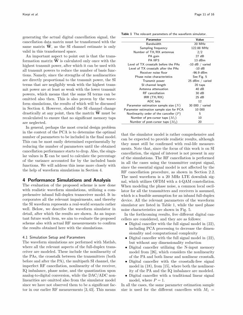
4.1 Simulation Setup and ParametersThe waveform simulations are performed with Matlab,where all the relevant aspects of the full-duplex trans-ceiver are modeled. These include the nonlinearity ofthe PAs, the crosstalk between the transmitters (bothbefore and after the PA), the multipath SI channel, theimperfect RF cancellation, nonlinearity of the receiver,IQ imbalance, phase noise, and the quantization uponanalog-to-digital conversion, while the DAC/ADC non-linearities are omitted also from the simulator modelsince we have not observed them to be a significant fac-tor in our earlier RF measurements [3, 43]. This means
Table 1 The relevant parameters of the waveform simulator.
Parameter ValueBandwidth 20 MHz
Sampling frequency 122.88 MHzNumber of TX/RX antennas 2/2
PA gain 27 dBPA IIP3 13 dBm
Level of TX crosstalk before the PAs -10 dB / variedLevel of TX crosstalk after the PAs -10 dB
Receiver noise floor -96.9 dBmPhase noise characteristics See Fig. 5
Transmit power 25 dBm / variedSI channel length 20 taps
Antenna attenuation 40 dBRF cancellation 30 dBIRR (TX/RX) 25 dB
ADC bits 12Parameter estimation sample size (N) 30 000 / varied
Parameter estimation sample size for PCA 10 000Nonlinearity order of the canceller (P ) 5
Number of pre-cursor taps (M1) 10Number of post-cursor taps (M2) 20
that the simulator model is rather comprehensive andcan be expected to provide realistic results, althoughthey must still be confirmed with real-life measure-ments. Note that, since the focus of this work is on SIcancellation, the signal of interest is not present in anyof the simulations. The RF cancellation is performedin all the cases using the transmitter output signal,since the essential signal model is not affected by theRF cancellation procedure, as shown in Section 2.2.The used waveform is a 20 MHz LTE downlink sig-nal, which utilizes OFDM with a 4-QAM constellation.When modeling the phase noise, a common local oscil-lator for all the transmitters and receivers is assumed,which is a feasible assumption for an inband full-duplexdevice. All the relevant parameters of the waveformsimulator are listed in Table 1, while the used phasenoise characteristics are shown in Fig. 5.
In the forthcoming results, five different digital can-cellers are considered, and they are as follows:• Digital canceller with the full signal model in (22),
including PCA processing to decrease the dimen-sionality and computational complexity
• Digital canceller with the full signal model in (22),but without any dimensionality reduction
• Digital canceller utilizing the N-input memorymodel from [26], which considers the nonlinearityof the PA and both linear and nonlinear crosstalk.
• Digital canceller with the crosstalk-free signalmodel in (18), from [15], where both the nonlinear-ity of the PA and the IQ imbalance are modeled.
• Digital canceller with a traditional linear signalmodel, where P = 1.
In all the cases, the same parameter estimation samplesize is used for the different cancellers with M1 =

Korpi et al. Page 12 of 16
Frequency offset from carrier (Hz)100 102 104 106 108
Pha
se n
oise
(dB
c/H
z)
-160
-140
-120
-100
-80
-60
-40
Figure 5 The phase noise characteristics used in the waveformsimulator, corresponding to a charge-pump type phase lockedloop based oscillator, taken from:http://datasheets.maximintegrated.com/en/ds/MAX2870.pdf.
10 and M2 = 20 to ensure a fair comparison. ThePCA matrix is calculated using 10 000 samples inthe initial channel estimation stage. Furthermore, toavoid overfitting when estimating and cancelling the SI,separate portions of the signal are used for calculatingthe SI channel estimate and evaluating the actual SIcancellation performance.
4.2 ResultsFirst, the signal spectra after the different digital can-cellers are shown in Fig. 6 using the default parameters,alongside with the spectra of the RF cancelled signaland the receiver noise floor. It can be observed that onlythe digital cancellers utilizing the full signal model canobtain sufficient levels of SI cancellation. In particular,the digital canceller utilizing the linear signal modeland the nonlinear crosstalk signal model from [26] per-form very poorly since in this case IQ imbalance isthe dominant source of distortion. The signal modelfrom [15], on the other hand, has insufficient model-ing accuracy since it does not take into account thecrosstalk. Thereby, it is necessary to model both theIQ imbalance and the crosstalk, together with the non-linearity of the PA, to obtain sufficient levels of digitalcancellation. Furthermore, based on Fig. 6, the numberof basis functions can be reduced to 35 % without anyreduction in the cancellation performance when usingthe full signal model.
Note that in this case the phase noise has no sig-nificant effect on the residual SI power since a com-mon local oscillator between the transmitters and re-ceivers is assumed. This results in a certain level ofself-cancellation of the phase noise upon downconver-sion, considerably reducing its significance [44].
Frequency (MHz)-15 -10 -5 0 5 10 15
PS
D [d
Bm
/200
kH
z]
-120
-110
-100
-90
-80
-70
-60
-50
-40
-30Before digital cancellation (-50.1 dBm)Linear signal model (-72.6 dBm)Nonlinear signal model with crosstalk [26] (-73.1 dBm)Nonlinear signal model with IQ imbalance and without crosstalk [15] (-87.5 dBm)Full signal model without PCA processing (-95.9 dBm)Full signal model with PCA processing (35 %) (-96 dBm)Receiver noise floor (-96.9 dBm)
Figure 6 The signal spectra after the different digitalcancellers, alongside with the spectra of the RF cancelled signaland the receiver noise floor.
Figure 7 shows then the increase in the effective noisefloor due to the residual SI for the different digitalcancellers, with respect to the total transmit power. Inother words, the closer to 0 dB the canceller achieves,the better is its overall SI cancellation performance.As expected, the linear canceller is not capable of effi-cient cancellation even with the lowest transmit powers,whereas the nonlinear cancellers with IQ imbalancemodeling suppress the SI nearly perfectly up to trans-mit powers of 20 dBm. Moreover, the digital cancellerutilizing the nonlinear crosstalk signal model from [26]performs very poorly with the whole transmit powerrange since it does not model the IQ imbalance, asalready discussed.
With transmit powers beyond 20 dBm, the crosstalkeffects begin to decrease also the accuracy of thecrosstalk-free nonlinear signal model from [15]. On theother hand, the full signal models perform relativelywell even with the highest transmit powers, resulting inonly a very minor increase in the noise floor. Further-more, as observed earlier, retaining only 35 % of theterms after the PCA processing does not seem to de-crease the accuracy of the signal model when comparedto the full signal model with all the terms included.In fact, the performance of the digital canceller withthe lower transmit powers is slightly improved by thedimensionality reduction since the smaller number ofparameters results in a more accurate parameter vectorestimate, and hence in more efficient cancellation.
To investigate the PCA-based dimensionality reduc-tion in greater detail, Fig. 8 shows the increase in thenoise floor with respect to the percentage of the termsincluded after the PCA, when using the full signalmodel in (22). The performance of the case withoutany PCA processing is also shown for reference. It can

Korpi et al. Page 13 of 16
Total transmit power (dBm)0 5 10 15 20 25
Incr
ease
in th
e no
ise
floor
(dB
)
0
5
10
15
20
25
30
Linear signal modelNonlinear signal model with crosstalk [26]Nonlinear signal model with IQ imbalance and without crosstalk [15]Full signal model without PCA processingFull signal model with PCA processing (35 %)
Figure 7 The increase in the noise floor due to residual SI, withrespect to the total transmit power.
Percentage of included terms (%)10 20 30 40 50 60 70 80 90 100
Incr
ease
inth
eno
ise
floor
(dB
)
0
5
10
15
20
25
30
35
40
With PCA processingWithout PCA processing (all terms included)
0.8
1
1.2
Figure 8 The increase in the noise floor due to residual SI, withrespect to the percentage of included terms.
be observed from the figure that there is a wide rangeof values for the percentage of included terms that pro-vide the same cancellation performance. However, if thepercentage of included terms goes significantly below35 %, the performance of the PCA-based canceller israther poor. This is caused by the decreased accuracyof the signal model due to excluding some of the sig-nificant terms. Also note that when 50–80 % of theterms are included, the PCA-based solution achievesslightly higher levels of SI cancellation than the can-celler without PCA processing. The reason for thisis the decreased variance of the parameter estimate,thanks to the smaller number of terms.
In order to minimize the computational complexityof the cancellation procedure, the number of includedterms must obviously be minimized. Hence, the small-est number of terms that still provides the requiredperformance is in this sense the optimal choice. Figure 8
Crosstalk level before the PAs (dBm)-20 -18 -16 -14 -12 -10 -8 -6 -4
Incr
ease
inth
eno
ise
floor
(dB
)
0
5
10
15
20
25
30
Linear signal modelNonlinear signal model with crosstalk [26]Nonlinear signal model with IQ imbalance and without crosstalk [15]Full signal model without PCA processingFull signal model with PCA processing (35 %)
Figure 9 The increase in the noise floor due to residual SI, withrespect to the level of the crosstalk before the PAs.
Parameter estimation sample size (N)3000 6000 12000 24000 48000
Incr
ease
in th
e no
ise
floor
(dB
)
0
5
10
15
20
25
30
Linear signal modelNonlinear signal model with crosstalk [26]Nonlinear signal model with IQ imbalance and without crosstalk [15]Full signal model without PCA processingFull signal model with PCA processing (35 %)
Figure 10 The increase in the noise floor due to residual SI,with respect to the parameter estimation sample size (N).
indicates that, with the parameters considered in thesesimulations, the optimal percentage of included termsis roughly 35 %, which corresponds to 840 coefficientswith the considered nonlinearity order and number ofmemory taps.
Since the level of the crosstalk occurring before thetransmitter PAs is obviously the most significant aspectin determining whether the full signal model is actu-ally necessary, Fig. 9 shows then the performance ofthe different digital cancellers with different crosstalklevels. It can be observed that, with the consideredtransmit power of 25 dBm, the crosstalk has a rathersignificant effect already at the level of −20 dB, sinceusing the nonlinear signal model without any crosstalkmodeling from [15] results in a 3 dB higher noise floorthan when using the full signal models. With highercrosstalk levels, the performance difference is obviouslyfurther emphasized. Furthermore, similar to the ear-

Korpi et al. Page 14 of 16
lier observations, the signal models that do not modelthe IQ imbalance perform very poorly since it is thedominant source of distortion.
It can also be observed from Fig. 9 that a largernumber of terms is required with the very high crosstalklevels. In particular, having only 35 % of the termsretained results in a somewhat higher residual SI powerthan retaining all of the terms. This is explained by thefact that higher crosstalk levels also result in a largernumber of significantly powerful SI terms. Nevertheless,the cancellation performance differences between thefull signal models, with or without PCA processing,are still relatively small with these reasonable crosstalklevels.
In order to further investigate the differences in thecomputational complexity of the different digital can-cellers, Fig. 10 shows their performance for differentparameter estimation sample sizes (N). It can be ob-served that the signal models without sufficient mod-eling accuracy are not bottlenecked by the amountof available learning data, since their performance islargely unaffected by the value of N . The benefits ofthe PCA-based dimensionality reduction for the fullsignal model are also clearly apparent, since the casewith 35 % of the terms retained performs relativelywell even with very small parameter estimation samplesizes. As opposed to this, without any dimensionalityreduction, roughly N = 24000 is required to obtain asufficiently accurate estimate of the parameters. Over-all, it is hence clear that the PCA processing helps insignificantly reducing the computational complexity ofthe digital SI cancellation procedure when utilizing thefull signal model.
5 ConclusionIn this paper, a novel digital self-interference cancellerfor a nonlinear MIMO inband full-duplex transceiverwas presented. The canceller is based on a compre-hensive signal model for the SI observed in the digitaldomain, which includes the effect of crosstalk occurringbetween the transmit chains, while also incorporatingthe most significant RF imperfections. Furthermore,it was also shown that the signal model is valid forvarious different RF cancellers. To control the com-plexity of the cancellation procedure, a novel principalcomponent analysis based scheme was then proposed,which can be used to control the number of parame-ters in the signal model. With the help of waveformsimulations, the proposed digital canceller was shownto cancel the SI nearly perfectly, even when its com-putational complexity was significantly reduced usingprincipal component analysis.
Appendix – Power Amplifier Output Signalunder CrosstalkLet us define a signal y(n) as follows:
y(n) =N∑
i=1αixi(n),
where αi is a scaling constant and xi(n) are knownsignals. To express an arbitrary integer power p of thesignal y(n) in terms of the signals xi(n), let us expandthe corresponding equation accordingly.
y(n)p =(α1x1(n) +
N∑i=2
αixi(n))p
.
Applying now the binomial theorem to the above ex-pression, we obtain
y(n)p =p∑
k1=0
(p
k1
)(α1x1(n))k1
(N∑
i=2
αixi(n)
)p−k1
Applying the binomial theorem in a similar mannerto the expression
(∑Ni=2 αixi(n)
)p−k1, we get
y(n)p =p∑
k1=0
[(p
k1
)(α1x1(n))k1
×
(α2x2(n) +
N∑i=3
αixi(n))p−k1
=
p∑k1=0
[(p
k1
)(α1x1(n))k1
[p−k1∑k2=0
[(p− k1
k2
)
× (α2x2(n))k2
(N∑
i=3αixi(n)
)p−k1−k2
=p∑
k1=0
p−k1∑k2=0
(p
k1
)(p− k1
k2
)(α1x1(n))k1
× (α2x2(n))k2
(N∑
i=3αixi(n)
)p−k1−k2
.
Applying the binomial theorem again to the expression(∑Ni=3 αixi(n)
)p−k1−k2and continuing in a similar

Korpi et al. Page 15 of 16
manner, we finally obtain the following equation:
(N∑
i=1αixi(n)
)p
=p∑
k1=0
p−k1∑k2=0
· · ·p−k1−···−kN−2∑
kN−1=0(p
k1
)(p− k1
k2
)· · ·(p− k1 − · · · − kN−2
kN−1
)× x1(n)k1x2(n)k2 · · ·xN (n)p−k1−···−kN−1
=p∑
k1=0
p−k1∑k2=0
· · ·p−k1−···−kN−2∑
kN−1=0Ak1,... ,kN−1
× x1(n)k1x2(n)k2 · · ·xN (n)p−k1−···−kN−1 ,
where Ak1,... ,kN−1 is a constant.
Competing interestsThe authors declare that they have no competing interests.
AcknowledgementsThe research work leading to these results was funded by the Academy ofFinland (under the project #259915 ”In-band Full-Duplex MIMOTransmission: A Breakthrough to High-Speed Low-Latency MobileNetworks”), the Finnish Funding Agency for Technology and Innovation(Tekes, under the project ”Full-Duplex Cognitive Radio”), TampereUniversity of Technology Graduate School, Nokia Foundation, Tuula andYrjo Neuvo Research Fund, and Emil Aaltonen Foundation.
References1. Duarte, M., Dick, C., Sabharwal, A.: Experiment-driven
characterization of full-duplex wireless systems. IEEE Transactions onWireless Communications 11(12), 4296–4307 (2012)
2. Heino, M., Korpi, D., Huusari, T., Antonio-Rodrıguez, E.,Venkatasubramanian, S., Riihonen, T., Anttila, L., Icheln, C., Haneda,K., Wichman, R., Valkama, M.: Recent advances in antenna designand interference cancellation algorithms for in-band full-duplex relays.IEEE Communications Magazine 53(5), 91–101 (2015)
3. Korpi, D., Choi, Y.-S., Huusari, T., Anttila, S. L. Talwar, Valkama, M.:Adaptive nonlinear digital self-interference cancellation for mobileinband full-duplex radio: algorithms and RF measurements. In: Proc.IEEE Global Communications Conference (GLOBECOM) (2015)
4. Riihonen, T., Werner, S., Wichman, R.: Mitigation of loopbackself-interference in full-duplex MIMO relays. IEEE Transactions onSignal Processing 59(12), 5983–5993 (2011)
5. Choi, J.I., Jain, M., Srinivasan, K., Levis, P., Katti, S.: Achievingsingle channel full duplex wireless communication. In: Proc. 16thAnnual International Conference on Mobile Computing andNetworking, pp. 1–12 (2010)
6. Jain, M., Choi, J.I., Kim, T., Bharadia, D., Seth, S., Srinivasan, K.,Levis, P., Katti, S., Sinha, P.: Practical, real-time, full duplex wireless.In: Proc. 17th Annual International Conference on Mobile Computingand Networking, pp. 301–312 (2011)
7. Bharadia, D., Katti, S.: Full duplex MIMO radios. In: Proc. 11thUSENIX Conference on Networked Systems Design andImplementation, pp. 359–372 (2014)
8. Sabharwal, A., Schniter, P., Guo, D., Bliss, D., Rangarajan, S.,Wichman, R.: In-band full-duplex wireless: Challenges andopportunities. IEEE Journal on Selected Areas in Communications32(9) (2014)
9. Choi, Y.-S., Shirani-Mehr, H.: Simultaneous transmission andreception: Algorithm, design and system level performance. IEEETransactions on Wireless Communications 12(12), 5992–6010 (2013)
10. Everett, E., Sahai, A., Sabharwal, A.: Passive self-interferencesuppression for full-duplex infrastructure nodes. IEEE Transactions onWireless Communications 13(2), 680–694 (2014)
11. Liu, G., Yu, F.R., Ji, H., Leung, V.C.M., Li, X.: In-band full-duplexrelaying: A survey, research issues and challenges. IEEECommunications Surveys & Tutorials 17(2), 500–524 (2015)
12. Zhang, Z., Shen, Y., Shao, S., Pan, W., Tang, Y.: Full duplex 2x2MIMO radios. In: Proc. Sixth International Conference on WirelessCommunications and Signal Processing (WCSP), pp. 1–6 (2014)
13. Balatsoukas-Stimming, A., Belanovic, P., Alexandris, K., Burg, A.: Onself-interference suppression methods for low-complexity full-duplexMIMO. In: Proc. 47th Asilomar Conference on Signals, Systems andComputers, pp. 992–997 (2013)
14. Alexandris, K., Balatsoukas-Stimming, A., Burg, A.:Measurement-based characterization of residual self-interference on afull-duplex MIMO testbed. In: Proc. IEEE 8th Sensor Array andMultichannel Signal Processing Workshop (SAM), pp. 329–332 (2014)
15. Anttila, L., Korpi, D., Antonio-Rodrıguez, E., Wichman, R., Valkama,M.: Modeling and efficient cancellation of nonlinear self-interference inMIMO full-duplex transceivers. In: Proc. IEEE Globecom Workshops,pp. 862–868 (2014)
16. Day, B.P., Margetts, A.R., Bliss, D.W., Schniter, P.: Full-duplexbidirectional MIMO: Achievable rates under limited dynamic range.IEEE Transactions on Signal Processing 60(7), 3702–3713 (2012)
17. Zhang, Z., Chen, Z., Shen, M., Xia, B.: Spectral and energy efficiencyof multipair two-way full-duplex relay systems with massive MIMO.IEEE Journal on Selected Areas in Communications 34(4), 848–863(2016)
18. Xia, X., Xu, Y., Xu, K., Zhang, D., Ma, W.: Full-duplex massiveMIMO AF relaying with semiblind gain control. IEEE Transactions onVehicular Technology 65(7), 5797–5804 (2016)
19. Xia, X., Zhang, D., Xu, K., Ma, W., Xu, Y.: Hardware impairmentsaware transceiver for full-duplex massive MIMO relaying. IEEETransactions on Signal Processing 63(24), 6565–6580 (2015)
20. Huusari, T., Choi, Y.-S., Liikkanen, P., Korpi, D., Talwar, S., Valkama,M.: Wideband self-adaptive RF cancellation circuit for full-duplexradio: Operating principle and measurements. In: Proc. IEEE 81stVehicular Technology Conference (VTC Spring) (2015)
21. Ngo, H.Q., Suraweera, H.A., Matthaiou, M., Larsson, E.G.: Multipairfull-duplex relaying with massive arrays and linear processing. IEEEJournal on Selected Areas in Communications 32(9), 1721–1737(2014)
22. Zayani, R., Bouallegue, R., Roviras, D.: Crossover neural networkpredistorter for the compensation of crosstalk and nonlinearity inMIMO OFDM systems. In: Proc. 21st Annual IEEE InternationalSymposium on Personal, Indoor and Mobile Radio Communications,pp. 966–970 (2010)
23. Amin, S., Landin, P.N., Handel, P., Ronnow, D.: Behavioral modelingand linearization of crosstalk and memory effects in RF MIMOtransmitters. IEEE Transactions on Microwave Theory and Techniques62(4), 810–823 (2014)
24. Sadeghpour, T., Alhameed, R.A., Ali, N.T., Elfergani, I.T.E., Dama,Y., Anoh, O.O.: Linear and nonlinear crosstalk in MIMO OFDMtransceivers. In: Proc. 18th IEEE International Conference onElectronics, Circuits and Systems (ICECS), pp. 504–507 (2011)
25. Qi, J., Aıssa, S.: Analysis and compensation for the joint effects ofHPA nonlinearity, I/Q imbalance and crosstalk in MIMO beamformingsystems. In: Proc. IEEE Wireless Communications and NetworkingConference, pp. 1562–1567 (2011)
26. Saffar, D., Boulejfen, N., Ghannouchi, F.M., Gharsallah, A., Helaoui,M.: Behavioral modeling of MIMO nonlinear systems withmultivariable polynomials. IEEE Transactions on Microwave Theoryand Techniques 59(11), 2994–3003 (2011)
27. Amiri, M.V., Bassam, S.A., Helaoui, M., Ghannouchi, F.M.:Matrix-based orthogonal polynomials for MIMO transmitterlinearization. In: Proc. 15th IEEE International Workshop on ComputerAided Modeling, Analysis and Design of Communication Links andNetworks (CAMAD), pp. 57–60 (2010)
28. Abdelhafiz, A., Behjat, L., Ghannouchi, F.M., Helaoui, M., Hammi, O.:A high-performance complexity reduced behavioral model and digitalpredistorter for MIMO systems with crosstalk. IEEE Transactions onCommunications 64(5), 1996–2004 (2016)
29. Anttila, L., Korpi, D., Syrjala, V., Valkama, M.: Cancellation of poweramplifier induced nonlinear self-interference in full-duplex transceivers.

Korpi et al. Page 16 of 16
In: Proc. 47th Asilomar Conference on Signals, Systems andComputers, pp. 1193–1198 (2013)
30. Korpi, D., Anttila, L., Syrjala, V., Valkama, M.: Widely linear digitalself-interference cancellation in direct-conversion full-duplextransceiver. IEEE Journal on Selected Areas in Communications 32(9),1674–1687 (2014)
31. Balatsoukas-Stimming, A., Austin, A., Belanovic, P., Burg, A.:Baseband and RF hardware impairments in full-duplex wireless systems:experimental characterisation and suppression. EURASIP Journal onWireless Communications and Networking 2015(142) (2015)
32. Korpi, D., Huusari, T., Choi, Y.-S., Anttila, L., Talwar, S., Valkama,M.: Digital self-interference cancellation under nonideal RFcomponents: Advanced algorithms and measured performance. In:Proc. IEEE 16th International Workshop on Signal ProcessingAdvances in Wireless Communications (SPAWC), pp. 286–290 (2015)
33. Anttila, L.: Digital front-end signal processing with widely-linear signalmodels in radio devices. PhD thesis, Tampere University of Technology(2011)
34. Isaksson, M., Wisell, D., Ronnow, D.: A comparative analysis ofbehavioral models for RF power amplifiers. IEEE Transactions onMicrowave Theory and Techniques 54(1), 348–359 (2006)
35. Ding, L., Zhou, G.T., Morgan, D.R., Ma, Z., Kenney, J.S., Kim, J.,Giardina, C.R.: A robust digital baseband predistorter constructedusing memory polynomials. IEEE Transactions on Communications52(1), 159–165 (2004)
36. Anttila, L., Handel, P., Valkama, M.: Joint mitigation of poweramplifier and I/Q modulator impairments in broadbanddirect-conversion transmitters. IEEE Transactions on MicrowaveTheory and Techniques 58(4), 730–739 (2010)
37. Ku, H., Kenney, J.S.: Behavioral modeling of nonlinear RF poweramplifiers considering memory effects. IEEE Transactions onMicrowave Theory and Techniques 51(12), 2495–2504 (2003)
38. Duarte, M., Sabharwal, A.: Full-duplex wireless communications usingoff-the-shelf radios: Feasibility and first results. In: Proc. 44th AsilomarConference on Signals, Systems, and Computers, pp. 1558–1562(2010)
39. Duarte, M., Sabharwal, A., Aggarwal, V., Jana, R., Ramakrishnan,K.K., Rice, C.W., Shankaranarayanan, N.K.: Design andcharacterization of a full-duplex multiantenna system for WiFinetworks. IEEE Transactions on Vehicular Technology 63(3),1160–1177 (2014)
40. Bharadia, D., McMilin, E., Katti, S.: Full duplex radios. In: Proc.SIGCOMM’13, pp. 375–386 (2013)
41. Jolliffe, I.T.: Principal Component Analysis, 2nd Ed. Springer, NewYork (2002)
42. Abdelhafiz, A., Kwan, A., Hammi, O., Ghannouchi, F.M.: Digitalpredistortion of LTE-A power amplifiers usingcompressed-sampling-based unstructured pruning of volterra series.IEEE Transactions on Microwave Theory and Techniques 62(11),2583–2593 (2014)
43. Korpi, D., Tamminen, J., Turunen, M., Huusari, T., Choi, Y.-S.,Anttila, L., Talwar, S., Valkama, M.: Full-duplex mobile device:Pushing the limits. IEEE Communications Magazine 54(9), 80–87(2016)
44. Syrjala, V., Yamamoto, K., Valkama, M.: Analysis and designspecifications for full-duplex radio transceivers under RF oscillatorphase-noise with arbitrary spectral shape. IEEE Transactions onVehicular Technology 65(8), 6782–6788 (2016)