Embed Size (px)
Citation preview

1
Nonlinear Self-Interference Cancellation forFull-Duplex Radios: From Link- and System-Level
Performance PerspectivesMin Soo Sim, Student Member, IEEE, MinKeun Chung, Student Member, IEEE, Dongkyu Kim, Member, IEEE,
Jaehoon Chung, Dong Ku Kim, Senior Member, IEEE, and Chan-Byoung Chae, Senior Member, IEEE
Abstract—One of the promising technologies for LTE Evolutionis full-duplex radio, an innovation is expected to double the spec-tral efficiency. To realize full-duplex in practice, the main chal-lenge is overcoming self-interference, and to do so, researchershave developed self-interference cancellation techniques. Sincemost wireless transceivers use power amplifiers, especially incellular systems, researchers have revealed the importance ofnonlinear self-interference cancellation. In this article, we firstexplore several nonlinear digital self-interference cancellationtechniques. We then propose a low complexity pre-calibration-based nonlinear digital self-interference cancellation technique.Next we discuss issues about reference signal allocation and theoverhead of each technique. For performance evaluations, wecarry out extensive measurements through a real-time proto-type and link-/system-level simulations. For link-level analysis,we measure the amount of canceled self-interference for eachtechnique. We also evaluate system-level performances through3D ray-tracing-based simulations. Numerical results confirm thesignificant performance improvement over a half-duplex systemeven in interference-limited indoor environments.
Index Terms—Full-duplex radio, self-interference cancellation,nonlinear self-interference cancellation, 5th generation (5G) com-munications.
I. INTRODUCTION
As a solution to the tremendous expansion of mobile traffic,researchers have been developing, over the past several years,fifth generation (5G) wireless communication/Long Term Evo-lution (LTE) Evolution. One of the main requirements for thisservice is to provide a 1000-fold improvement in throughputover current fourth generation mobile networks such as LTEAdvanced [2]. To achieve this requirement, researchers havestrived to accomplish the following: improving spectral ef-ficiency (bps/Hz), expanding system bandwidth (Hz), and/orincreasing throughput per area (bps/m2). Several promisingtechnologies have been developed to improve spectral effi-ciency such as massive multiple-input and multiple-output(MIMO), 3-dimensional (3D) beamforming, and in-band full-duplex radios.
This article was presented in part at the IEEE Globecom FDWC Workshop2016 [1].
M. S. Sim, M. Chung, D. K. Kim, and C.-B. Chae are with Yonsei Univer-sity, Korea (E-mail: {simms, minkeun.chung, dkkim, cbchae}@yonsei.ac.kr).D. Kim and J. Chung are with LG Electronics (E-mail: {dkyu.kim, jae-hoon.chung}@lge.com).
This work was in part supported by the the MISP under the “ICTConsilience Creative Program” (IITP-2015-R0346-15-1008), the ICT R&DProgram of MSIP/IITP (B0126-15-1017), and LG Electronics.
Macro-cell BS
Signal-of-interestSelf-interference Self-interference cancellation MS
Small-cell BS
(a) (b)
Relay node
Fig. 1. Scenarios of full-duplex-radio-based LTE systems. (a) A full-duplexLTE relay system and (b) a full-duplex LTE small-cell system.
In-band full-duplex radios (full-duplex radios hereafter)simultaneously transmit and receive on the same frequencyband [1], [3]–[11]. Full-duplex systems are expected, by defi-nition, to double the spectral efficiency of half-duplex systems.Current commercial systems, however, have engaged with littleattention to this type of system due to its propensity for self-interference. Self-interference is the phenomenon of a signal,transmitted from a transmitter, being received by its ownreceiver while that receiver is trying to receive a signal sentfrom another device (signal-of-interest). The self-interference,which is generally far stronger than signal-of-interest, makes itimpossible for a device to decode the signal-of-interest. Today,mobile networks, so as to avoid self-interference, operate inhalf-duplex. Frequency-division duplex (FDD) systems pre-vent self-interference by allocating different frequency bandsfor uplink and downlink. Time-division duplex (TDD) systemstransmit and receive at different times. To deal with the self-interference issue in full-duplex systems, researchers havedeveloped several self-interference cancellation techniques, theobjective of which is to mitigate or cancel the self-interferenceto noise level.
Applying full-duplex technology, due to its high transmitpower, is a challenge in cellular networks such as LTE. Typicalfull-duplex systems provide self-interference cancellation ofapproximately 120 dB [5], [6]. For a macro-cell base station
arX
iv:1
607.
0191
2v2
[cs
.IT
] 1
5 Fe
b 20
17

2
TX
RX⇡
Antenna CancellationTX
RX
Dual-Polarized Antenna
TX
RX
CirculatorTX
RX
Antenna Separation
⌧n
�n
an
⌃
Tunable RF Circuit
Digital Self-Interference Cancellation
Self-interference characteristic estimation
TX signal
RX signal
Reconstruct self-interference
Self-interference modelx[n] or X[k]
y[n] or Y [k]
h[n], H[k] or bk,l
Isolation
Analog self-interference cancellation circuit
PA I/Q mixer
I/Q mixer
DAC
ADC
Digital self-interference cancellation block
LNA
Isolation
⌃ ⌃-+
-+
TX
RX
Fig. 2. A full-duplex transceiver with self-interference cancellation techniques. Representative isolation, active analog self-interference cancellation, and digitalself-interference cancellation schemes are illustrated.
(BS) whose transmission power is up to 46 dBm and anoise level of -90 dBm, it is not feasible to suppress self-interference to the noise level. Therefore, applications of full-duplex radio in LTE systems could be limited to relay systemsor small-cell systems where transmission power is at most23 dBm (see Fig. 1). To apply full duplex to these scenarios,the nonlinearity of power amplifiers becomes a bottleneck ofself-interference cancellation. Power amplifier’s nonlinearity isone of the imperfections of radio-frequency (RF) transceivers;other imperfections include in-phase and quadrature (I/Q)imbalances and phase noise. Since these RF imperfectionsare not sufficiently suppressed in the analog domain, digitalself-interference cancellation should share the burden. Most ofthe digital processing in conventional communication systems,however, is designed linearly. Therefore, special tech that canhandle this nonlinearity are required for the processing toperform self-interference cancellation well.
In this article, we investigate several techniques that cancancel nonlinear self-interference. We introduce the concepts,compare reference signal allocations, and evaluate link- andsystem-level performances. To the best of our knowledge, thisis the first attempt to investigate system-level performances offull-duplex radios based on measured data.
The rest of this article is organized as follows. In Section II,we introduce several self-interference cancellation techniquesincluding isolation, active analog cancellation, and linear dig-ital cancellation. Section III details representative nonlinear
digital self-interference cancellation techniques. We investigatelink- and system-level performance evaluations in Section IV,and our conclusions are given in Section V.
II. AN OVERVIEW OF SELF-INTERFERENCECANCELLATION TECHNIQUES
Most prior work on full-duplex radios has focused ondesigning a wireless transceiver that can perform a sufficientamount of self-interference cancellation. Included in suchwork are the following: 1) designing an antenna and configura-tion that lessen coupling between a transmitter and a receiver,2) suppressing self-interference by mimicking the analog self-interference signal and subtracting from it, and 3) cancelingdigitalized self-interference by modeling self-interference andsubtracting from it. Figure 2 illustrates a schematic of severalself-interference cancellation technologies. The ultimate goalis to maximize a total cancellation amount by integrating andoptimizing these techniques. In this section, to show howself-interference cancellation works in full-duplex systems, webriefly introduce some of the conventional self-interferencecancellation techniques.
A. Analog Self-Interference Cancellation
Analog self-interference cancellation suppresses self-interference in the analog domain, i.e., before the signal passesthrough an analog-to-digital converter (ADC). The main roleof analog self-interference cancellation is to take up a portion
3
of the total cancellation amount and to make sure that theresidual self-interference can be canceled out in the digitaldomain. Since the cancellation performance in the digitaldomain is limited by the dynamic range of an ADC, analogself-interference cancellation should suppress certain portionsof self-interference. According to tunability or adaptability,analog self-interference can be categorized, in this article, asisolation (a.k.a. passive analog self-interference cancellation)and active analog self-interference cancellation.
1) Isolation: Isolation suppresses self-interference signalsin the analog domain without any adaptive tuning. Specialantenna structures and configurations, and passive devices areemployed to weaken, passively, self-interference signals. Abasic method for isolation is antenna separation, which causespath-loss between a transmit antenna and a receive antenna [7].All transceivers that use different antennas for transmittersand receivers can obtain self-interference suppression gain.A circulator was employed for the system that transmittersand receivers share antennas [5]. A circulator is a three-portdevice that transfers a transmit signal from a transmit port toan antenna and a receive signal from an antenna to a receiveport while the signal from the transmit port is blocked fromthe receiver port. With a dual-polarized antenna, a leakagefrom a transmitter to a receiver can be prevented despitethe short physical distance [3]. To obtain extra isolation, atechnique called antenna cancellation was proposed, whichuses a symmetric antenna configuration and a π-phase shifterto take advantage of destructive interference [8].
2) Active Analog Self-Interference Cancellation: Activeanalog self-interference cancellation, through adaptive tuningand algorithms, aims at the dominant components of self-interference. The dominant components here represent a line-of-sight component of a system with separate transmit andreceive antennas, or a leakage from a circulator of a systemwith a single transceiver antenna. A typical solution of activeanalog self-interference is a tunable RF circuit [4], [5]. Thecircuit, which consists of several taps with RF componentssuch as attenuators, phase shifters, and delays, uses a replicaof the transmitted signal as an input, and tries to mimic theself-interference signal. Since the circuit directly exploits thetransmitted signal’s RF imperfections, which in the digitaldomain is in fact hard to handle, it would have a better chanceof suppressing the self-interference in analog cancellation. Tofollow the time-varying characteristic of the self-interferencechannel, a real-time adaptive algorithm and extra referencesignal are needed to control RF components. Note that min-imizing a noise of the RF circuit, which can be achieved byemploying passive devices that generate virtually no noise, isessential for stable cancellation [11]. Other analog cancellationof generating an RF signal with an auxiliary transmit chainwas also introduced in [7], [10], where the RF signal fromthe auxiliary chain was combined with the received signalto suppress self-interference. With a MIMO system, self-interference can be suppressed by transmit beamforming [11].
B. Linear Digital Self-Interference Cancellation
Digital self-interference cancellation cancels out the residualself-interference from analog self-interference cancellation.Generally, a line-of-sight component or a direct leakage ofa circulator is suppressed by analog self-interference cancel-lation, but non-line-of-sight components (reflections) are not.Therefore, these components should be removed by digitalcancellation. There are three steps for digital cancellation:1) set a model of a self-interference signal, 2) estimate thechannel, and 3) reconstruct the self-interference signal andsubtract it from a received signal. Note that, in digital self-interference cancellation, a reference signal is needed not onlyfor a self-interference, but also for a signal-of-interest.
Many researchers use, due to its simplicity, a linear modelfor a wireless channel. Therefore, self-interference channelsare assumed to be linear, and linear self-interference cancella-tion becomes the basic technology of digital self-interferencecancellation. In this article, we introduce two kinds of linearestimation methods and the following reference signal alloca-tions. For simplicity, we assume orthogonal frequency-divisionmultiplexing (OFDM) with the extended cyclic prefix (CP).
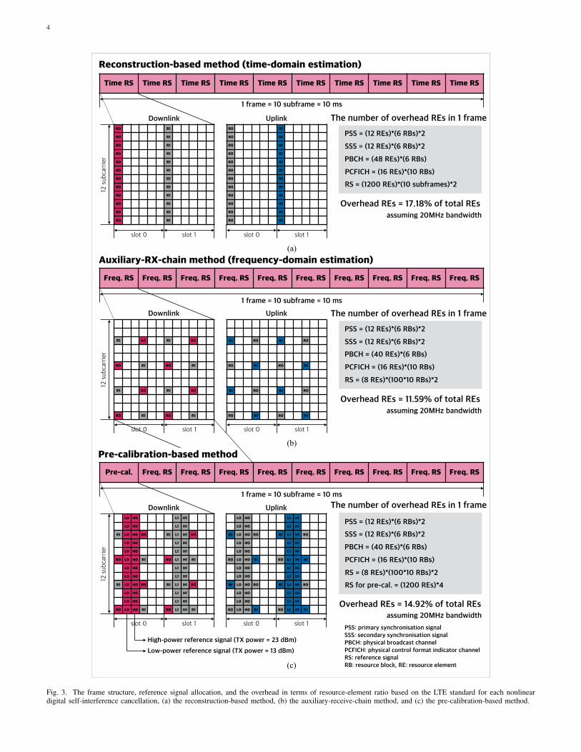
1) Linear Digital Cancellation in Time Domain: The firstmethod is to estimate the self-interference channel in thetime domain [5]. Consider a full-duplex system that adopts,as shown in Fig. 3(a), one OFDM symbol as a referencesignal. In this case, the self-interference channel is obtainedby the least squares method in the time domain. Note thatthis method should exploit the reference signal allocated inall subcarriers. To overcome the Doppler effect, however,the reference signals should be repeated, which creates atremendous overhead for the reference signal. Furthermore,since the channel-estimation part includes pseudo-inverse op-erations, and the self-interference reconstruction part includesconvolution operations, this method has high computationalcomplexity.
2) Linear Digital Cancellation in Frequency Domain: Itis more natural to allocate the reference signal as shown inFig. 3(b) [3], which is a structure similar to that used in theLTE standard. This reference signal is used for both the self-interference link and the desired link. With this pattern, theself-interference channel can be calculated by the least squaresmethod in the frequency domain. In other words, the channelis obtained by dividing a received signal passed through a fastFourier transform (FFT) block by the reference signal beforean inverse FFT (IFFT) block. This method has relatively lowcomplexity since it only requires element-wise multiplicationsand divisions, and interpolations.
III. NONLINEAR SELF-INTERFERENCE CANCELLATION
The need to cancel nonlinearity arises when we attemptto apply full-duplex radios to systems with high transmissionpower. Suppose that current LTE systems support a trans-mission power of 23 dBm. With analog cancellation thatsuppresses self-interference by approximately 60 dB [3], [5],[6], digital cancellation has the burden of self-interference tocancel of 50 dB (≈ 23 dBm - (-90 dBm) - 60 dB). Digitalcancellation, however, is limited by intermodulation distortion
4
R1 R0 R1 R0
R0 R1 R0 R1
R1 R0 R1 R0
R0 R1 R0 R1
R1 R0 R1 R0
R0 R1 R0 R1
R1 R0 R1 R0
R0 R1 R0 R1
slot 0 slot 1 slot 0 slot 1
R0 R1
R0 R1
R0 R1
R0 R1
R0 R1
R0 R1
R0 R1
R0 R1
R0 R1
R0 R1
R0 R1
R0 R1
slot 0 slot 1
L0 H0 L1 H1
L0 H0 L1 H1
R1 L0 H0 R0 R1 L1 H1 R0
L0 H0 L1 H1
L0 H0 L1 H1
R0 L0 H0 R1 R0 L1 H1 R1
L0 H0 L1 H1
L0 H0 L1 H1
R1 L0 H0 R0 R1 L1 H1 R0
L0 H0 L1 H1
L0 H0 L1 H1
R0 L0 H0 R1 R0 L1 H1 R1
L0 H0 L1 H1
L0 H0 L1 H1
R1 L0 H0 R0 R1 L1 H1 R0
L0 H0 L1 H1
L0 H0 L1 H1
R0 L0 H0 R1 R0 L1 H1 R1
L0 H0 L1 H1
L0 H0 L1 H1
R1 L0 H0 R0 R1 L1 H1 R0
L0 H0 L1 H1
L0 H0 L1 H1
R0 L0 H0 R1 R0 L1 H1 R1
slot 0 slot 1 slot 0 slot 1
High-power reference signal (TX power = 23 dBm)Low-power reference signal (TX power = 13 dBm)
R0 R1
R0 R1
R0 R1
R0 R1
R0 R1
R0 R1
R0 R1
R0 R1
R0 R1
R0 R1
R0 R1
R0 R1
Time RS Time RS Time RS Time RS Time RS Time RS Time RS Time RS Time RS Time RS
1 frame = 10 subframe = 10 ms
Freq. RS Freq. RS Freq. RS Freq. RS Freq. RS Freq. RS Freq. RS Freq. RS Freq. RS Freq. RS
Pre-cal. Freq. RS Freq. RS Freq. RS Freq. RS Freq. RS Freq. RS Freq. RS Freq. RS Freq. RS
Reconstruction-based method (time-domain estimation)
Auxiliary-RX-chain method (frequency-domain estimation)
12 subcarrier
12 subcarrier
slot 0 slot 1
12 subcarrier
Downlink Uplink
Downlink Uplink
Downlink Uplink
PSS = (12 REs)*(6 RBs)*2
SSS = (12 REs)*(6 RBs)*2
PBCH = (48 REs)*(6 RBs)
PCFICH = (16 REs)*(10 RBs)
RS = (1200 REs)*(10 subframes)*2
Overhead REs = 17.18% of total REs
1 frame = 10 subframe = 10 ms
1 frame = 10 subframe = 10 ms
The number of overhead REs in 1 frame
PSS = (12 REs)*(6 RBs)*2
SSS = (12 REs)*(6 RBs)*2
PBCH = (40 REs)*(6 RBs)
PCFICH = (16 REs)*(10 RBs)
RS = (8 REs)*(100*10 RBs)*2
Overhead REs = 11.59% of total REs
PSS = (12 REs)*(6 RBs)*2
SSS = (12 REs)*(6 RBs)*2
PBCH = (40 REs)*(6 RBs)
PCFICH = (16 REs)*(10 RBs)
RS = (8 REs)*(100*10 RBs)*2
Overhead REs = 14.92% of total REs
RS for pre-cal. = (1200 REs)*4
(a)
(b)
(c)
Pre-calibration-based method
PSS: primary synchronisation signal SSS: secondary synchronisation signal PBCH: physical broadcast channel PCFICH: physical control format indicator channel RS: reference signal RB: resource block, RE: resource element
The number of overhead REs in 1 frame
The number of overhead REs in 1 frame
assuming 20MHz bandwidth
assuming 20MHz bandwidth
assuming 20MHz bandwidth
Fig. 3. The frame structure, reference signal allocation, and the overhead in terms of resource-element ratio based on the LTE standard for each nonlineardigital self-interference cancellation, (a) the reconstruction-based method, (b) the auxiliary-receive-chain method, and (c) the pre-calibration-based method.

5
(a)
(b)
(c)
PA
LNA
I/Q mixer DAC
I/Q mixer ADC
Power amplifier model
Lpa + Lch# of taps =Joint nonlinearity model
Wireless channel model
K(Lpa + Lch)# of parameters =
x[n]
y[n]
PA
LNA
LNA
x0[n]
Auxiliary RX chain
I/Q mixer DAC
I/Q mixer ADC
x[n]
y[n]
Wireless channel model
I/Q mixer ADC
# of parameters =Nsub
PA
LNA
x[n]
y[n]
I/Q mixer DAC
I/Q mixer ADC
Pre-cal. function calculation
Pre-cal.
Pre-cal. block
Power amplifier model
Wireless channel model# of parameters =Nsub
# of parameters =KLpa
Wireless channel
Wireless channel
Wireless channel
to estimate
to estimate
to estimate
# of taps =Lch
Lpa# of taps =
to estimate
Lpa# of taps =
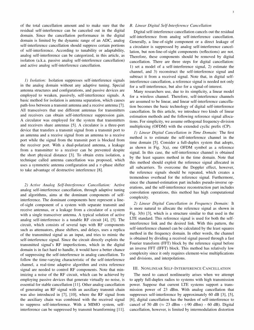
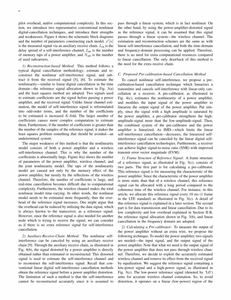
Fig. 4. The schematic block diagram of each nonlinear digital self-interference cancellation method, and the number of parameters constructing each model,(a) the reconstruction-based method, (b) the auxiliary-receive-chain method, and (c) the pre-calibration-based method.
(IMD), caused by a power amplifier. Therefore, several tech-niques, called nonlinear digital self-interference cancellation,have been proposed to cancel the self-interference with IMD.
A. Nonlinearity Models
As explained in Section II-B, the first step in digital self-interference cancellation is determining what model to adopt.For decades, a challenging problem has been overcomingthe nonlinearity of power amplifiers. Several theoretical ap-proaches for modeling the nonlinearity have been developedsuch as the Wiener model and the Hammerstein model. In thisarticle, we introduce the parallel Hammerstein model adoptedin prior work [5], [6]. The parallel Hammerstein model isexpressed as:
y[n] =
K−1∑k=0
L−1∑`=0
bk,`|x[n− `]|2kx[n− `],
where x[n] and y[n] are the power amplifier’s time-domaincomplex baseband input and output signals, {bk,`} are the
coefficients of the model, and 2K − 1 and L represent theorder of the model and the number of the model’s taps. Notethat the number of {bk,`} is KL. This model is constructed ofodd-order terms of the input signal because in wireless com-munication systems the only thing considered is a passbandsignal near a center frequency. It can be inferred that the modelbecomes memoryless if L = 1, and linear if K = 1.
Expressed in terms of the complex baseband signals, theparallel Hammerstein model can be affected by I/Q imbal-ances. The effect of I/Q imbalances can be avoided by em-ploying the real-valued model introduced in [11]. The authorsin [6] introduced the polynomial basis function, which includesthe effect of I/Q imbalances. In this article, we assume that thesystem follows the parallel Hammerstein model, which can bedirectly applied to LTE systems.
B. Conventional Nonlinear Cancellation Techniques
In contrast to canceling linear components, canceling non-linear components calls for extra resources such as hardware,
6
pilot overhead, and/or computational complexity. In this sec-tion, we introduce two representative conventional nonlineardigital-cancellation techniques, and introduce their strengthsand weaknesses. Figure 4 shows the schematic block diagramsand the number of parameters constructing each model. x′[n]is the measured signal via an auxiliary receive chain. Lch is thedelay spread of a self-interference channel, Lpa is the numberof memory taps of a power amplifier, and Nsub is the numberof used subcarriers.
1) Reconstruction-based Method: This method follows atypical digital cancellation methodology; estimate and re-construct the nonlinear self-interference signal, and sub-tract it from the received signal [5], [6]. To estimate thenonlinearity—similar to linear digital cancellation in the timedomain—the reference signal allocation shown in Fig. 3(a)and the least squares method are adopted. Two signals usedto estimate coefficients are the signal before passing a poweramplifier, and the received signal. Unlike linear channel esti-mation, the model of self-interference signal is reformulatedinto odd-order terms, and the number of the coefficientsto be estimated is increased K-fold. The larger number ofcoefficients causes more complex computation to estimatethem. Furthermore, if the number of coefficients is greater thanthe number of the samples of the reference signal, it makes theleast squares problem something that should be avoided—anundetermined system.
The major weakness of this method is that the nonlinearitymodel consists of both a power amplifier and a wirelessself-interference channel. This is why the number of thecoefficients is abnormally large. Figure 4(a) shows the numberof parameters of the power amplifier, wireless channel, andthe joint nonlinearity model. The taps of the nonlinearitymodel are caused not only by the memory effect of thepower amplifier, but mostly by the reflections of the wirelesschannel. Therefore, the number of coefficients is large, andreal-time cancellation becomes difficult due to computationalcomplexity. Furthermore, the wireless channel makes the totalnonlinear model time-varying. In other words, the nonlinearmodel needs to be estimated more frequently, thus the over-head of the reference signal increases. One might argue thatthe overhead can be reduced by utilizing the data signal, whichis always known to the transceiver, as a reference signal.However, since the reference signal is also needed for anothernode which is trying to receive the signal, we can consideras if there is no extra reference signal for self-interferencecancellation.
2) Auxiliary-Receive-Chain Method: The nonlinear self-interference can be canceled by using an auxiliary receivechain [9]. Through the auxiliary receive chain, as illustrated inFig. 4(b), the signal distorted by a power amplifier is directlyobtained rather than estimated or reconstructed. This distortedsignal is used to estimate the self-interference channel andto reconstruct the self-interference signal. Recall that con-ventional linear digital self-interference cancellation methodsobtain the reference signal before a power amplifier distortion.The limitation of such a method is that the self-interferencecannot be reconstructed accurately since it is assumed to
pass through a linear system, which is in fact nonlinear. Onthe other hand, by using the power-amplifier-distorted signalas the reference signal, it can be assumed that this signalpasses through a linear system—the wireless channel. Theestimation and reconstruction schemes are the same as withlinear self-interference cancellation, and both the time-domainand frequency-domain processing can be applied. Therefore,there is no need for extra computational resources comparedto linear cancellation. The only drawback of this method isthe need for the extra receive chain.
C. Proposed Pre-calibration-based Cancellation Method
To cancel nonlinear self-interference, we propose a pre-calibration-based cancellation technique which linearizes atransmitter and cancels self-interference with linear-only can-cellation at a receiver. A pre-calibrator, as illustrated inFig. 4(c), estimates the nonlinearity of a power amplifier,and modifies the input signal of the power amplifier tolinearize the output signal of the power amplifier. Put sim-ply, since the signal with a high amplitude is saturated bythe power amplifier, a pre-calibrator strengthens the high-amplitude-signal more than the low-amplitude-signal. Then,the combined system of the pre-calibrator and the poweramplifier is linearized. As IMD—which limits the linearself-interference cancellation—decreases, the linearized self-interference signal can be canceled by the linear digital self-interference cancellation technologies. Furthermore, a receivercan achieve higher signal-to-noise ratio (SNR) with improvedtransmit error vector magnitude (EVM).
1) Frame Structure of Reference Signal: A frame structureof a reference signal, as illustrated in Fig. 3(c), consists oftwo parts. The first part is for calculating a pre-calibrator.This reference signal is for measuring the characteristic of thepower amplifier. Since the characteristic of the power amplifieris more static than that of a wireless channel, this referencesignal can be allocated with a long period compared to thecoherence time of the wireless channel. For instance, in thisarticle, we allocate this reference signal every 10 ms (1 framein the LTE standard) as illustrated in Fig. 3(c). A detail ofthis reference signal is explained in a later section. The secondpart is for data transmission and linear cancellation. Due to itslow complexity and low overhead explained in Section II-B,the reference signal allocation shown in Fig. 3(b), and linearcancellation in the frequency domain are adopted.
2) Calculating a Pre-calibrator: To measure the output ofthe power amplifier without an extra wire, we propose thefollowing technique. To model the power amplifier, two signalsare needed—the input signal, and the output signal of thepower amplifier. Note that what we need is the output signal ofthe power amplifier that does not pass through wireless chan-nel. Therefore, we decide to exploit the accurately estimatedwireless channel and remove its effect from the received signalby equalization. We suggest the reference signal containing alow-power signal and a high-power signal, as illustrated inFig. 3(c). The low-power reference signal (denoted by ‘L0’)aims for accurate wireless channel estimation. So, to avoiddistortion, it operates on a linear (low-power) region of the

7
power amplifier, and to lessen estimation errors, it occupiesall subcarriers. The high-power reference signal (denoted by‘H0’) is for estimating the power amplifier’s distortion. Thissignal experiences a nonlinear (high-power) region of thepower amplifier, and undergoes sufficient distortion. Then,using the precisely estimated wireless channel, the output ofthe power amplifier can be calculated.
There are several conventional methods to calculate a pre-calibration function. The method used in this article is toestimate coefficients of a polynomial-based pre-calibrationfunction. It is just like estimating a nonlinearity model, butuses the input of the power amplifier as output and vice versato estimate a reversed function. The pre-calibration functionis obtained from the reversed function of the power amplifier,and scaling the power amplifier gain.
3) Strengths of Proposed Method: The proposed methodhas two main strengths compared to the conventional methods.First, there is no need for extra receive chain or wire. Tech-niques for power amplifier linearization have been applied tomost conventional radios with high power. One of the effectivetechnologies to reduce the nonlinearity of a transmitter isdigital pre-distortion (DPD) [12]. However, most DPD systemsneed a secondary receive chain to estimate the output of thepower amplifier [12]. In [10], a full-duplex system whichmeasures the effect of the power amplifier through a cable,and applies to an auxiliary transmit signal was proposed. Withfull-duplex systems, since a receiver is able to sense a transmitsignal without saturation, a pre-calibration function can becalculated without extra receive chain and cable.
Second, complex and time-varying nonlinear cancellation isnot required. Contrary to the reconstruction-based method, thepre-calibration-based method takes advantages of the nonlinearmodel of the power amplifier without the effect of wirelesschannels. It is, therefore, expected that the coefficients {bk,`}are more static and fewer in number, which lessens theburden of computational complexity and the reference-signaloverhead. For example, with the proposed reference signalillustrated in Fig. 3(c), as shown in Fig. 4, KLpa coefficientsneed to be estimated every 10 ms, while the reconstruction-based method estimates K(Lpa+Lch) coefficients every 1 ms.
IV. PERFORMANCE EVALUATIONS
We evaluate the nonlinear digital self-interference cancella-tion techniques from two points of view: link-level evaluationsfor measuring nonlinearity of a power amplifier and can-cellation amounts, and system-level evaluations for through-put gain. A basic criterion of self-interference cancellationtechnologies is the amount of cancellation. This is importantbecause it guarantees the feasibility of full-duplex radios.
Simple link-level evaluations, however, do not fully ex-plain why nonlinear digital cancellation is needed despiteits high complexity. Most prior work has tried to suppressself-interference to the same level as the noise floor, but itis questionable whether this is really necessary in practicewhere there is other interferences. Therefore, we also carry out,with a 3D ray-tracing tool, system-level simulations of multi-BSs and multi-mobile stations (MSs) in an indoor environ-ment. The link-/system-level analyses were based on computer
simulations. To obtain a realistic power amplifier model, wemeasured the characteristics of a power amplifier via anLTE-based software-defined radio platform that we developed.To model a 3D indoor environment and obtain path-lossesbetween nodes, a 3D ray-tracing tool was employed.
A. Link-Level Self-Interference Cancellation Performance
To simulate nonlinear digital cancellation, we assume asingle-input and single-output (SISO) wireless system basedon the LTE parameters given in Fig. 5(a). To exploit a realisticmodel for a power amplifier, we measure the nonlinearity ofa power amplifier1 through the PXIe software-defined radioplatform2 introduced in [3]. This platform generates an LTE-based signal with given physical-layer parameters. As shownin Fig. 5(b), the input and output (distorted) signals of thepower amplifier are measured via the PXIe platform. A 30 dBattenuator is employed to receive the output signal of thepower amplifier without distortion from the receiver of thePXIe platform. The GUI of the LTE downlink framework,which is shown in Fig. 5(d), shows the received signal haspassed through the power amplifier. Figure 5(c) shows themeasured input and output signals of the power amplifier,and a parallel-Hammerstein-model-based approximated poweramplifier model for simulations. In this simulation, the poweramplifier was modeled as the third order model, which showedthe greatest similarity with the measured data. Tending tomake the residual self-interference channel frequency se-lective, analog self-interference cancellation is simulated byemploying a longer-than-normal delay-spread for the residualself-interference channel and attenuating the channel 50 dB.
The three nonlinear digital cancellation techniques intro-duced in Section III-B and Section III-C were evaluated, andcompared with a frequency-domain linear digital cancella-tion. The reference signal of the reconstruction-based methodwas determined to be repeated every subframe (12 OFDMsymbols) considering the Doppler effect and the referencesignal overhead, as illustrated in Fig. 3(a). For the linearcancellation part of the auxiliary-receive-chain method andthe pre-calibration-based method, the frequency-domain-basedlinear cancellation was adopted, and the reference signalpattern followed the cell-specific reference signal in LTE, asseen in Fig. 3(b). The orders of the reconstructed parallelHammerstein model and the pre-calibration function are 7 and5, respectively.
We simulated the amount of cancellation with differentcoherence times. Figures 5(e), and 5(f) show how much self-interference power was reduced when the coherence times ofthe self-interference channel were 7.14 ms, and 142.86 ms,respectively. These coherence times were calculated fromthe Doppler effect, assuming that the center frequency was2.52 GHz, and MSs were vehicles (60 km/h) or pedestrians
1Mini-Circuits ZVA-183W+ Super Ultra Wideband Amplifier,http://www.minicircuits.com/pdfs/ZVA-183W+.pdf
2With this platform, we developed and demonstrated the real-time full-duplex SISO and MIMO systems in IEEE GLOBECOM 2014 and IEEEGLOBECOM 2015, respectively. Full demo video clips are available athttp://www.cbchae.org/

8
Parameter Value
Center frequency 2.52 GHz
Bandwidth 20 MHz
FFT size 2048
Used subcarrier 1200
CP length 512
TX power 23 dBm
Power amplifier gain 29 dB
Power amplifier P1dB 28 dBm
Analog cancellation 50 dB
Noise floor -90 dBm
Resolution of the ADC 14 bits
(a)
(e) (f) (g)
0 200 400 600 800 1000Time [ms]
-50
-45
-40
-35
-30
-25
-20
-15
-10
Can
cella
tion
amou
nt [d
B]
linear SICnonlinear SIC w/ reconstructingnonlinear SIC w/ auxiliary RXnonlinear SIC w/ pre-cal.
(b) (c)
PXIe platform
Power amplifier
30dB attenuator
0 0.5 1 1.5 2Input
0
10
20
30
40
50
60
Out
put
measured datapower amp. model
0 200 400 600 800 1000Time [ms]
-60
-55
-50
-45
-40
-35
-30
Can
cella
tion
amou
nt [d
B] linear SICnonlinear SIC w/ reconstructingnonlinear SIC w/ auxiliary RXnonlinear SIC w/ pre-cal.
0 200 400 600 800 1000Time [ms]
-65
-60
-55
-50
-45
-40
-35
-30
Can
cella
tion
amou
nt [d
B] linear SICnonlinear SIC w/ reconstructingnonlinear SIC w/ auxiliary RXnonlinear SIC w/ pre-cal.
(d)
LTE Downlink Framework
Fig. 5. (a) The parameters for link- and system-level simulations, (b) on the left side is a setup for measuring the characteristic of the power amplifier, andon the right side is the used power amplifier and the attenuator, (c) measured input and output signals of the power amplifier, and an approximated model ofthe power amplifier, (d) the GUI of the LTE downlink framework used for measuring the model of the power amplifier, (e), (f) the results of the link-levelsimulations with the coherence time of 7.13 ms, and 142.86 ms, and (g) the result of the link-level simulation with constant wireless channel.
(3 km/h). Figure 5(g) shows the amount of self-interferencecancellation with a static self-interference channel.
When the self-interference channel was static, the per-formance of the reconstruction-based method, as Fig. 5(g)
shows, was about 62 dB—the best performance among thethree nonlinear cancellation methods. This occurred becausethis method can reconstruct self-interference accurately (onlylimited by noise), but the other two methods were limited by

9
0 50 100 150Throughput [Mbps]
0
0.1
0.2
0.3
0.4
0.5
0.6
0.7
0.8
0.9
1
CD
F
HD downlinkFD linear SIC (random sche.)FD linear SIC (perfect sche.)FD nonl. SIC w/ recon. (random sche.)FD nonl. SIC w/ recon. (perfect sche.)FD nonl. SIC w/ aux. RX (random sche.)FD nonl. SIC w/ aux. RX (perfect sche.)FD nonl. SIC w/ pre-cal. (random sche.)FD nonl. SIC w/ pre-cal. (perfect sche.)
BS2BS5
BS4 BS3 BS1
[Mbps] HD downlink
FD linear SIC
(random sche.)
FD linear SIC
(perfect sche.)
FD nonl. SIC w/ recon. (random sche.)
FD nonl. SIC w/ recon. (perfect sche.)
FD nonl. SIC w/ aux. RX (random sche.)
FD nonl. SIC w/ aux. RX (perfect sche.)
FD nonl. SIC w/ pre-cal. (random sche.)
FD nonl. SIC w/ pre-cal. (perfect sche.)
Average 51.80 35.28 36.98 48.10 53.67 72.45 92.47 70.23 89.96Median 63.50 5.89 7.37 21.50 29.73 61.63 97.76 60.25 95.68
10-percentile 5.35 0.13 0.17 0.63 1.08 4.72 14.62 4.74 14.9590-percentile 82.16 133.16 134.17 140.32 141.23 153.96 154.44 148.19 148.64
-15-5 5
60
240
30
210
0
180
330
150
300
120
270 90
(a)
(b)
(c)
(d)
(e)
3rd floor
38m
98m
23dBm TX power
Potential gain by perfect scheduling
3D modeling
Fig. 6. (a) Topology for system-level performance evaluations, (b) BS deployments and cell coverages, (c) dual-polarized antenna and radiation pattern, (d)CDF of the system throughput, and (e) throughput results. Here, ‘random scheduling’ means random user selection and ‘perfect scheduling’ means Genie-aidedideal user selection.
channel estimation error from the interpolating process in thefrequency domain. On the other hand, it is observed that itscancellation performance is 43 dB when the coherence timewas 142.86 ms, and when the coherence time was 7.13 ms,even worse than that of linear self-interference cancellation.Therefore, we conclude that in practice it is not proper tocancel self-interference by reconstructing, due to its weaknessin the time-varying channel.
The auxiliary-receive-chain method and the pre-calibration-based method are robust to fading channel. Figure 5(e) showsthat, even though the coherence time was small, these methodscould cancel nonlinear self-interference by about 43 dB. Thisresult is quite obvious because the reference signals exploitthe very same structure of LTE. The performances of thesetwo methods degrade as coherence time decreases because of
an increase in the channel estimation error from the inter-polating process in the time domain. The auxiliary-receive-chain method behaves as a performance-upper-bound of thepre-calibration-based method because the pre-calibrator doesnot linearize ideally. One might argue that the performanceof the pre-calibration-based method is not as stable as that ofthe auxiliary-receive-chain method. This is because the pre-calibration function generator, which is calculated in everyframe, fails to generate the well-operating pre-calibrationfunction in some frames. By applying adaptive polynomialfilters [13], or orthogonal polynomials [14], we can have betterchance of improving performance. We leave this for futurework.

10
B. System-Level Throughput Gain
We investigated the need for nonlinear digital self-interference cancellation technologies from a system through-put perspective. For system-level evaluations, we used Wire-less System Engineering (WiSE)—a 3D ray-tracing tool de-veloped by Bell Labs [15], [16]. For an indoor environment,we modeled the building structure of Veritas Hall C of YonseiUniversity in Korea, shown in Fig. 6(a). Each BS is modeledwith the measured radiation pattern of the dual-polarizedantenna introduced in [3], [17] (see Fig. 6(c)). On the thirdfloor, there were uniformly distributed MSs, each of which wasequipped with an isotropic antenna; these were associated withthe BS that provided the strongest downlink power. Figure 6(b)illustrates how five BSs were deployed on the third floor, andhow each cell coverage was determined. Note that due to itsradiation pattern, each BS has its own direction, represented asan arrow in Fig. 6(b). For evaluations, we assumed that therewere five MSs, which were located in different cell coverages,and adopted the parameters in Fig. 5(a).
In system-level simulations, we investigated the throughputof a half-duplex downlink system based on FDD LTE, and full-duplex systems with different self-interference cancellationlevels. For the cancellation performances, we exploited theaverage of the link-level simulation results with the coherencetime of 142.86 ms in Section IV-A, and combined themwith analog cancellation of 50 dB given in Fig. 5(a). Theexact cancellation amounts were 84.28 dB for linear cancella-tion, 93.03 dB for reconstruction-based nonlinear cancellation,107.17 dB for auxiliary-receive chain nonlinear cancellation,and 106.20 dB for pre-calibration-based nonlinear cancella-tion. With the received power of signal-of-interest and thesummation of the received power of interferences and noise,signal-to-interference-plus-noise-ratio (SINR) of each nodewas calculated. Finally, a system bandwidth of 20 MHz andthe overheads introduced in Fig. 3 were applied. Note thatthere was also the overhead for the extended CP. We alsosimulated the full-duplex systems without considering MS-to-MS interference as upper bounds, which could be achieved byGenie-aided perfect scheduling.
Figure 6(d) illustrates the results of the ergodic throughputof the half-duplex system and the full-duplex systems withdifferent self-interference levels. The solid lines of full-duplexindicate results with MS-to-MS interference and the dashedlines indicate those without it. Figure 6(e) gives the representa-tive values of each case such as average, median, 10-percentile,and 90-percentile. The result implies that the throughput ofa full-duplex system depends heavily on the performanceof self-interference cancellation. If the full-duplex systememploys only linear self-interference cancellation, the averagethroughput is lower than that of the half-duplex system, andonly about 20% of MSs can experience the benefit of fullduplex. On the other hand, with the well-performing nonlinearself-interference cancellation techniques such as the auxiliary-receive-chain method or the pre-calibration-based method,the average throughput increased by approximately 35 to40% over that of a half-duplex system. Even though self-interference is canceled out sufficiently, we can observe that
for certain portions of MSs, half-duplex outperforms full-duplex. Furthermore, if the interference between MSs wasavoided somehow, the average throughput could be improvedby up to 79%. From this, we have the insight that once self-interference cancellation techniques guarantee certain perfor-mances, a critical issue in full-duplex research will becomeuser-allocation and user-scheduling.
V. CONCLUSION
Full-duplex radio is expected to play a major role inenhancing the spectral efficiency in 5G wireless communica-tions/LTE Evolution. In this article, we have investigated twoexisting nonlinear digital cancellation techniques and proposeda low complexity pre-calibration-based technique. Link-leveland system-level performances were analyzed through a real-time software-defined radio platform and a 3D-ray-tracing-based simulations of an indoor environment. The results ofour analysis confirmed a significant performance enhancementeven in interference-limited environments. We expect ourstudy to provide insights into developing practical cellularsystems based on full-duplex radios.
ACKNOWLEDGMENT
The authors would like to thank Mr. Y.-G. Lim for helpfuldiscussions on WiSE simulations.
REFERENCES
[1] M. S. Sim, M. Chung, D. K. Kim, and C.-B. Chae, “Low-complexitynonlinear self-interference cancellation for full-duplex radios,” to appearin Proc. IEEE Globecom FDWC Workshop, Dec. 2016.
[2] 5G Forum, “5G Vision, Requirements, and Enabling Technologies,”V.2.0, Mar. 2016.
[3] M. Chung, M. S. Sim, J. Kim, D. K. Kim, and C.-B. Chae, “Prototypingreal-time full duplex radios,” IEEE Comm. Mag., vol. 53, no. 9, pp. 56–63, Sep. 2015.
[4] M. Jain, J. I. Choi, T. M. Kim, D. Bharadia, S. Seth, K. Srinivasan,P. Levis, S. Katti, and P. Sinha, “Practical, real-time, full duplexwireless,” in Proc. of ACM MobiCom. ACM, 2011, pp. 301–312.
[5] D. Bharadia, E. McMilin, and S. Katti, “Full duplex radios,” in Proc. ofACM SIGCOMM. ACM, Aug. 2013, pp. 375–386.
[6] M. Heino, D. Korpi, T. Huusari, E. Antonio-Rodrı̀guez, S. Venkatasub-ramanian, T. Riihonen, L. Anttila, C. Icheln, K. Haneda, R. Wichman,and M. Valkama, “Recent advances in antenna design and interferencecancellation algorithms for in-band full duplex relays,” IEEE Comm.Mag., vol. 53, no. 5, pp. 91–101, May 2015.
[7] M. Duarte, A. Sabharwal, V. Aggarwal, R. Jana, K. K. Ramakrishnan,C. W. Rice, and N. K. Shankaranarayanan, “Design and characterizationof a full-duplex multiantenna system for WiFi networks,” IEEE Trans.on Veh. Technol., vol. 63, no. 3, pp. 1160–1177, Mar. 2014.
[8] E. Aryafar, M. A. Khojastepour, K. Sundaresan, S. Rangarajan, andM. Chiang, “MIDU: Enabling MIMO full duplex,” in Proc. of ACMMobiCom. ACM, Aug. 2012, pp. 257–268.
[9] E. Ahmed and A. M. Eltawil, “All-digital self-interference cancellationtechniques for full-duplex systems,” IEEE Trans. Wireless Comm.,vol. 14, no. 7, pp. 3519–3532, Jul. 2015.
[10] A. K. Khandani, “Full-duplex (two-way) Wireless: antennadesign and signal processing,” the technical report available:http://cst.uwaterloo.ca/reports/antenna design.pdf.
[11] Y. Hua, Y. Ma, A. Gholian, Y. Li, A. C. Cirik, and P. Liang, “Radioself-interference cancellation by transmit beamforming, all-analog can-cellation and blind digital tuning,” Sig. Proc., vol. 108, pp. 322–340,Mar. 2015.
[12] W.-J. Kim, S. P. Stapleton, J. H. Kim, and C. Edelman, “Digitalpredistortion linearizes wireless power amplifiers,” IEEE Microw. Mag.,vol. 6, no. 3, pp. 54–61, Sep. 2005.
[13] V. J. Mathews, “Adaptive polynomial filters,” IEEE Sig. Proc. Mag.,vol. 8, no. 3, pp. 10–26, Jul. 1993.

11
[14] R. Raich and G. T. Z. Zhou, “Orthogonal polynomials for complexGaussian processes,” IEEE Trans. Sig. Proc., vol. 52, no. 10, pp. 2788–2797, Oct. 2004.
[15] R. A. Valenzuela, D. Chizhik, and J. Ling, “Measured and predictedcorrelation between local average power and small scale fading in indoorwireless communication channels,” in Proc. IEEE Veh. Technol. Conf.,May 1998, pp. 2104–2108.
[16] J. Jang, M. Chung, H. G. Hwang, Y.-G. Lim, H.-J. Yoon, T. Oh, B.-W.Min, Y. Lee, K. S. Kim, C.-B. Chae, and D. K. Kim, “Smart small cellfor 5G: Theoretical feasibility and prototype results,” to appear in IEEEWireless Comm. in Dec. 2016, [Online] Available: arXiv:1506.09109.
[17] T. Oh, Y.-G. Lim, C.-B. Chae, and Y. Lee, “Dual-polarization slotantenna with high cross polarization discrimination for indoor small-cell MIMO systems,” IEEE Ant. and Wireless Prop. Lett., vol. 14, pp.374–377, Feb. 2014.
PLACEPHOTOHERE
Min Soo Sim (S’14) received his B.S. degree in theSchool of Integrated Technology from Yonsei Uni-versity, Korea, in 2014. He is now with the School ofIntegrated Technology, at the same university and isworking toward a Ph.D. degree. He was the recipientof the Silver Prize in the 22nd Humantech PaperContest. His research interest includes emergingtechnologies for 5G communications.
PLACEPHOTOHERE
MinKeun Chung (S’11) received his B.S. degree inthe School of Electrical and Electronic Engineeringfrom Yonsei University, Korea, in 2010. He is nowworking toward the Ph.D. degree under the jointsupervision of Prof. D. K. Kim and Prof. C.-B. Chae.He did his graduate intern in advanced wirelessresearch team at the National Instruments in Austin,TX, USA in 2013. His research interests include thedesign and implementation of architectures for next-generation wireless communication systems.
PLACEPHOTOHERE
Dongkyu Kim (M’13) received his B.S. degreein electrical engineering from Konkuk University,Seoul, South Korea, in 2006 and his M.S. and Ph.D.degrees in electrical and electronic engineering fromYonsei University, Seoul, in 2008 and 2013, respec-tively. From 2013 to 2014, he was a Post-DoctoralResearcher with the Information and Telecommu-nication Laboratory, Yonsei University. Since 2014,he has been with LG Electronics Inc. as a SeniorResearcher, where he was involved in developmentof advanced wireless technologies, including 5G
mobile communications and 3GPP standard for future wireless systems. Hiscurrent research activities are focused on future wireless communicationincluding flexible and full-duplex radio, V2X, massive MIMO, and mmWavetechnologies.
PLACEPHOTOHERE
Jaehoon Chung is with LG Electronics Inc., wherehe was involved in development of advanced wire-less technologies, including 5G mobile communica-tions and 3GPP standard for future wireless systems.
PLACEPHOTOHERE
Dong Ku Kim (SM’15) received his B.S. from Ko-rea Aerospace University in 1983, and his M.S. andPh.D. from the University of Southern California,Los Angeles, in 1985 and 1992, respectively. Heworked on CDMA systems in the cellular infrastruc-ture group of Motorola at Fort Worth, Texas, in 1992.He has been a professor in the School of Electricaland Electronic Engineering, Yonsei University since1994. Currently, he is a vice president for academicresearch affairs of the Korean Institute of Commu-nications and Information Systems (KICS). He has
been a vice chair of the executive committee of 5G Forum since 2013. Hereceived the Minister Award for the Distinguished Service for ICT R&D fromthe Ministry of Information, Science, and Future Planning in 2013, and theAward of Excellence in leadership of 100 Leading Core Technologies forKorea 2020 from the National Academy of Engineering of Korea. He receivedDr. Irwin Jacobs Academic Achievement Award 2016 from Qualcomm andKICS.
PLACEPHOTOHERE
Chan-Byoung Chae (SM’12) is an associate pro-fessor in the School of Integrated Technology, Yon-sei University. Before joining Yonsei University, hewas with Bell Labs, Alcatel-Lucent, Murray Hill,New Jersey, as a member of technical staff, andHarvard University, Cambridge, Massachusetts, as apostdoctoral research fellow. He received his Ph.D.degree in electrical and computer engineering fromthe University of Texas at Austin in 2008. He was therecipient/co-recipient of the IEEE INFOCOM BestDemo Award (2015), the IEIE/IEEE Joint Award for
Young IT Engineer of the Year (2014), the KICS Haedong Young ScholarAward (2013), the IEEE Signal Processing Magazine Best Paper Award(2013), the IEEE ComSoc AP Outstanding Young Researcher Award (2012),the IEEE Dan. E. Noble Fellowship Award (2008), and two Gold Prizes (1st)in the 14th/19th Humantech Paper Contest. He currently serves as an Editor forIEEE Transactions on Wireless Communications, the IEEE/KICS Journal onCommunications Networks, and IEEE Transactions on Molecular, Biological,and Multi-scale Communications.