Embed Size (px)
DESCRIPTION
Interference Cancellation in Huawei
Citation preview

7/18/2019 Interference Cancellation Feature
http://slidepdf.com/reader/full/interference-cancellation-feature 1/31
WCDMA RAN
Interference Cancellation Feature Parameter Description
Issue 02
Date 2013-09-30
HUAWEI TECHNOLOGIES CO., LTD.
Copyright © Huawei Technologies Co., Ltd. 2013. All rights reserved.
No part of this document may be reproduced or transmitted in any form or by any means without prior written consent of Huawei Technologies Co., Ltd.
Trademarks and Permissions
and other Huawei trademarks are trademarks of Huawei Technologies Co., Ltd.
All other trademarks and trade names mentioned in this document are the property of their respective holders.
NoticeThe purchased products, services and features are stipulated by the contract made between Huawei and the customer. All or part of the products, services and features described
in this document may not be within the purchase scope or the usage scope. Unless otherwise specified in the contract, all statements, information, and recommendations in this
document are provided "AS IS" without warranties, guarantees or representations of any kind, either express or implied.
The information in this document is subject to change without notice. Every effort has been made in the preparation of this document to ensure accuracy of the contents, but all
statements, information, and recommendations in this document do not constitute a warranty of any kind, express or implied.
Huawei Technologies Co., Ltd.
Address: Huawei Industrial Base Bantian, Longgang Shenzhen 518129 People's Republic of China
erence Cancellation Feature Parameter Description http://localhost:7891/pages/GEC0815J/02/GEC0815J/02/resourc
1 7/8/2015

7/18/2019 Interference Cancellation Feature
http://slidepdf.com/reader/full/interference-cancellation-feature 2/31
Website: http://www.huawei.com
Email: [email protected]
Contents
1 About This Document
1.1 Scope
1.2 Intended Audience1.3 Change History
2 Overview
2.1 Introduction
2.2 Benefits
2.2.1 CCPIC
2.2.2 CCPIC (Phase 2)
2.2.3 HSUPA UL IC
2.2.4 Turbo IC
3 Background Information
3.1 Multiuser Detection
3.2 Interference Cancellation
3.2.1 Demodulation-based IC and Decoding-based IC
3.2.2 Parallel and Successive Interference Cancellation4 Huawei Interference Cancellation Techniques
4.1 Introduction
4.1.1 Channel Types
4.1.2 Inter-board IC and Intra-board IC
4.2 DPCCH IC
4.2.1 CCPIC
4.2.2 CCPIC (Phase 2)
4.3 E-DPDCH IC
4.3.1 HSUPA UL IC
4.3.2 Turbo IC
4.4 Types of Base Stations and Boards Supporting IC
4.4.1 Types of Base Stations and Boards Supporting DPCCH IC
4.4.2 Types of Base Stations and Boards Supporting E-DPDCH IC
5 Related Features
5.1 WRFD-010210 Control Channel Parallel Interference Cancellation (CCPIC)
5.2 WRFD-140202 Control Channel Parallel Interference Cancellation (Phase 2)
5.3 WRFD-010691 HSUPA UL Interference Cancellation
5.4 WRFD-150206 Turbo IC
6 Network Impact
6.1 WRFD-010210 Control Channel Parallel Interference Cancellation (CCPIC)
6.2 WRFD-140202 Control Channel Parallel Interference Cancellation (Phase 2)
6.3 WRFD-010691 HSUPA UL Interference Cancellation
6.4 WRFD-150206 Turbo IC
7 Engineering Guidelines
7.1 WRFD-010210 Control Channel Parallel Interference Cancellation (CCPIC)
7.1.1 When to Use Control Channel Parallel Interference Cancellation (CCPIC)
7.1.2 Information to Be Collected
7.1.3 Deployment
7.1.3.1 Requirements
7.1.3.2 Data Preparation
7.1.3.3 Activation
7.1.3.4 Activation Observation
7.1.3.5 Deactivation
7.1.4 Performance Monitoring
7.1.5 Parameter Optimization
7.1.6 Troubleshooting
7.2 WRFD-140202 Control Channel Parallel Interference Cancellation (Phase 2)
7.2.1 When to Use Control Channel Parallel Interference Cancellation (Phase 2)
7.2.2 Information to Be Collected
erence Cancellation Feature Parameter Description http://localhost:7891/pages/GEC0815J/02/GEC0815J/02/resourc
1 7/8/2015

7/18/2019 Interference Cancellation Feature
http://slidepdf.com/reader/full/interference-cancellation-feature 3/31
7.2.3 Deployment
7.2.3.1 Requirements
7.2.3.2 Data Preparation
7.2.3.3 Activation
7.2.3.4 Activation Observation
7.2.3.5 Deactivation
7.2.4 Performance Monitoring
7.2.5 Parameter Optimization
7.2.6 Troubleshooting
7.3 WRFD-010691 HSUPA UL Interference Cancellation
7.3.1 When to Use HSUPA UL Interference Cancellation
7.3.2 Information to Be Collected
7.3.3 Deployment
7.3.3.1 Requirements
7.3.3.2 Data Preparation
7.3.3.3 Activation
7.3.3.4 Activation Observation
7.3.3.5 Deactivation
7.3.4 Performance Monitoring
7.3.5 Parameter Optimization
7.3.6 Troubleshooting
7.4 WRFD-150206 Turbo IC
7.4.1 When to Use Turbo IC
7.4.2 Information to Be Collected
7.4.3 Deployment
7.4.3.1 Requirements
7.4.3.2 Data Preparation
7.4.3.3 Activation
7.4.3.4 Activation Observation
7.4.3.5 Deactivation
7.4.4 Performance Monitoring
7.4.5 Parameter Optimization
7.4.6 Troubleshooting
8 Parameters
9 Counters
10 Glossary
11 Reference Documents1 About This Document
1.1 Scope
This document describes interference cancellation (IC), including its technical principles, related features, network impact, and engineering guidelines.
This document covers the following features:
WRFD-010210 Control Channel Parallel Interference Cancellation (CCPIC)
WRFD-140202 Control Channel Parallel Interference Cancellation (Phase 2)
WRFD-010691 HSUPA UL Interference Cancellation
WRFD-150206 Turbo IC
1.2 Intended Audience
This document is intended for personnel who:
Need to understand the features described herein
Work with Huawei products
1.3 Change History
This section provides information about the changes in different document versions. There are two types of changes, which are defined as follows:
Feature change
Changes in features of a specific product version
Editorial change
Changes in wording or addition of information that was not described in the earlier version
01 (2013-09-30)
This issue does not include any changes.
erence Cancellation Feature Parameter Description http://localhost:7891/pages/GEC0815J/02/GEC0815J/02/resourc
1 7/8/2015

7/18/2019 Interference Cancellation Feature
http://slidepdf.com/reader/full/interference-cancellation-feature 4/31
Draft A (2013-07-30)
Compared with issue Issue 01 (2013-04-28) of RAN15.0, Draft A (2013-07-30) of RAN15.1 includes the following changes.
Change Type Change Description Parameter Change
Feature change Added descriptions about interference cancellation performed on coordinated l inks to section
4.1.1 Channel Types.
None
Optimized the steps for activating CCPIC (Phase 2) in section 7.2.3 Deployment.
Editorial change For the 3900 series base stations, the BTS3902E, and the BTS3803E, changed the fol lowing
MML command names:
MOD LOCELL has been changed to MOD ULOCELL.
SET RESALLOCRULE has been changed to SET NODEBRESALLOCRULE.
For details, see section 7.3.3 Deployment.
Changed the parameter ID name
from IC_MODE to ICMODE .
Added descriptions about whether the BTS3803E and BTS3902E support Interference
Cancellation in hardware dependency descriptions.
None
2 Overview
2.1 Introduction
Wideband Code Division Multiple Access (WCDMA) is a self-interference system. The capacity and performance of the system are limited by inter-user interference
(also known as multiple access interference or MAI), especially near-far interference. Near-far interference is signal interference that occurs when a desirable signal
from a far-away user is interfered by the signals from another user close to the intended receiver.
Multiuser detection (MUD), also known as joint detection, is a receiver technique to detect desired signals from interference and noise. MUD can minimize MAI,
intersymbol interference (ISI), and near-far interference, thereby improving system capacity and performance.
IC is one type of MUD. Huawei introduces the following four IC techniques:
Control Channel Parallel Interference Cancellation (CCPIC)
CCPIC is used for the Dedicated Physical Control Channel (DPCCH) and corresponds to the WRFD-010210 Control Channel Parallel Interference
Cancellation (CCPIC) feature.
CCPIC (Phase 2)
CCPIC (Phase 2) is also used for the DPCCH and corresponds to the WRFD-140202 Control Channel Parallel Interference Cancellation (Phase 2) feature.
High Speed Uplink Packet Access (HSUPA) UL IC
HSUPA UL IC is used for the E-DCH Dedicated Physical Control Channel (E-DPDCH) and corresponds to the WRFD-010691 HSUPA UL Interference
Cancellation feature.
Turbo IC
Turbo IC is also used for the E-DPDCH.
2.2 Benefits
IC estimates the MAI by signal detection and regeneration and cancels some or all interference before the final demodulation and decoding. This increases the uplinksystem capacity.
The following sections describe the benefits provided by different IC techniques.
2.2.1 CCPIC
Each UE is allocated a standalone DPCCH. Uplink interference from this channel reduces the uplink system capacity.
CCPIC cancels interference from the DPCCH, thereby reducing the interference from this DPCCH on other channels and increasing the uplink system capacity. The
gains are obvious when the uplink DPCCH uses a large proportion of the received total wideband power (RTWP) in the cell. For example, the gains are obvious when
a large number of UEs camp on the cell and the uplink throughput is low.
2.2.2 CCPIC (Phase 2)
As an enhancement to CCPIC, CCPIC (Phase 2) improves CCPIC efficiency and extends the range in which CCPIC can take effect, thereby significantly increasing
the uplink system capacity. The gains are obvious when the uplink DPCCH uses a large proportion of the RTWP in the cell. For example, the gains are obvious when a
large number of UEs camp on the cell and the uplink throughput is low.
2.2.3 HSUPA UL IC
HSUPA UL IC cancels interference from the E-DPDCH and reduces the MAI, thereby improving demodulation performance and increasing the uplink system capacity.
2.2.4 Turbo IC
Turbo IC improves E-DPDCH IC efficiency for HSUPA 2 ms TTI UEs, thereby reducing interference between UEs and significantly increasing the uplink system
capacity.
3 Background Information
This section provides background information about the IC feature. It covers MUD, parallel interface cancellation (PIC), and successive interface cancellation (SIC).
3.1 Multiuser Detection
In single-user scenarios, noise consists of N0, ISI, and external interference, including that from neighboring cells.
In multi-user scenarios, interference between UEs is also considered noise. This type of interference is called multi-user interference (MUI) or MAI.
Table 3-1 describes the noise types.
erence Cancellation Feature Parameter Description http://localhost:7891/pages/GEC0815J/02/GEC0815J/02/resourc
1 7/8/2015

7/18/2019 Interference Cancellation Feature
http://slidepdf.com/reader/full/interference-cancellation-feature 5/31
Table 3-1 Noise types
Noise Type Description
N0 N0 indicates background noise, which is also called noise floor. It is caused by the thermal motion of electrons in internal
components and its strength depends on the receiver bandwidth and ambient temperature.
ISI Intersymbol interference (ISI) is a form of waveform distortion and multipath spread of consecutive symbols. ISI is usually
caused by multipath propagation.
MAI Multiple access interference (MAI) indicates interference between UEs, which is caused by the multiple-access
technique. In a CDMA system, UEs are identified by their scrambling codes in the uplink. However, scrambling codes are
not completely orthogonal. Therefore, there is MAI between uplink UEs.
The conventional detection technique uses a matched filter to despread received signals and makes a decision on the filter output. The receiver does not consider MAI
or use transmission information of other UEs for a joint detection.
The MUD technique enables the receiver to detect signals from a UE by considering the MAI from all other UEs. This increases the system's anti-interference
capabilities, effectively utilizes uplink spectrum resources, and greatly increases system capacity. IC is a first-choice MUD technique for the third-generation mobile
communications system. It can improve receiver performance and leave room for further expansion.
3.2 Interference Cancellation
IC estimates the MAI by signal detection and regeneration and cancels some or all interference before the final demodulation and decoding.
IC can be categorized in the following ways:
IC is categorized into demodulation-based IC and decoding-based IC based on whether regeneration and cancellation are performed after demodulation or
decoding.
IC is categorized into parallel interference cancellation (PIC) and successive interference cancellation (SIC) based on whether IC is performed in parallel or
in succession.
3.2.1 Demodulation-based IC and Decoding-based IC
Demodulation-based IC
Demodulation-based IC implements regeneration and cancellation on demodulated signals for a UE before decoding. This minimizes interference to other
UEs and improves demodulation performance. Figure 3-1 illustrates demodulation-based IC.
Figure 3-1 Demodulation-based IC
As shown in Figure 3-1, demodulation-based IC involves the following operations:
Demodulation: Upon receiving signals from UEs, the NodeB demodulation module demodulates signals of different UEs or signals on different channels
based on information such as finger delays and the channel estimation result.
Decoding: Upon receiving the demodulated signals of a UE, the NodeB decoding module retrieves the primitive information of the UE.
Regeneration: The NodeB regeneration module estimates and regenerates the primitive signals of the UE or on the channel based on information such as
the demodulation/decoding result, channel estimation result, and multipath conditions.
Cancellation: The NodeB cancellation module removes the regenerated signals of the UE from the received signals to cancel any interference to other UEs
or channels.
Decoding-based IC
Decoding-based IC implements regeneration and cancellation on decoded signals for a UE. This minimizes interference to other UEs and improves
demodulation performance. Figure 3-2 illustrates decoding-based IC.
Figure 3-2 Decoding-based IC
erence Cancellation Feature Parameter Description http://localhost:7891/pages/GEC0815J/02/GEC0815J/02/resourc
1 7/8/2015

7/18/2019 Interference Cancellation Feature
http://slidepdf.com/reader/full/interference-cancellation-feature 6/31
3.2.2 Parallel and Successive Interference Cancellation
Parallel Interference Cancellation
With PIC, the NodeB performs detection, regeneration, and cancellation of signals of multiple UEs in parallel. PIC can be implemented in multiple stages to further
improve performance. Figure 3-3 illustrates two-stage PIC.
Figure 3-3 Two-stage PIC
As illustrated in Figure 3-3, PIC in each stage involves three operations: detection, regeneration, and cancellation. Upon receiving signals, the NodeB detection module
detects signals for different UEs by demodulation or by demodulation and decoding. After implementing first-stage and second-stage PIC, the NodeB demodulates anddecodes the signals where PIC is performed to obtain the decoded signals of UEs.
Successive Interference Cancellation
With SIC, the NodeB performs detection and regeneration on signals of only one UE at a time. The NodeB removes the regenerated signals of a UE before detecting
the next UE to reduce the MAI from this UE on subsequent UEs. SIC can be implemented in multiple stages to further improve performance. Figure 3-4 illustrates
two-stage SIC.
Figure 3-4 Two-stage SIC
erence Cancellation Feature Parameter Description http://localhost:7891/pages/GEC0815J/02/GEC0815J/02/resourc
1 7/8/2015

7/18/2019 Interference Cancellation Feature
http://slidepdf.com/reader/full/interference-cancellation-feature 7/31
4 Huawei Interference Cancellation Techniques
4.1 Introduction
This section describes the Huawei interference cancellation techniques DPCCH IC and E-DPDCH IC.
4.1.1 Channel Types
In WCDMA, the physical channels DPCCH and DPDCH are introduced to the uplink to support basic R99 circuit switched (CS) and packet switched (PS) services. The
E-DPCCH and E-DPDCH are added as uplink physical channels to support HSUPA, which is introduced in 3GPP Release 6 to meet requirements for uplink data
transmission. Figure 4-1 shows channels used when an R99 UE and an HSUPA-capable UE are processing an R99 and HSUPA service, respectively.
Figure 4-1 Channels for R99 and HSUPA services
DPCCH: Dedicated Physical Control Channel
DPDCH: Dedicated Physical Data Channel
E-AGCH: E-DCH Absolute Grant Channel
E-DPCCH: E-DCH Dedicated Physical Control Channel
E-DPDCH: E-DCH Dedicated Physical Data Channel
E-HICH: E-DCH HARQ Acknowledgement Indicator Channel
E-RGCH: E-DCH Relative Grant Channel
CCPIC and CCPIC (Phase 2) take effect on Tthe DPCCH uses CCPIC and CCPIC (Phase 2), and HSUPA UL IC and Turbo IC take effect on the E-DPDCH uses
HSUPA UL IC and Turbo IC, as shown in the following figure.
erence Cancellation Feature Parameter Description http://localhost:7891/pages/GEC0815J/02/GEC0815J/02/resourc
1 7/8/2015

7/18/2019 Interference Cancellation Feature
http://slidepdf.com/reader/full/interference-cancellation-feature 8/31
When the WRFD-151205 Uplink CoMP (Joint Reception) and WRFD-151206 HetNet Uplink CoMP(Joint Reception) features are activated, IC also takes effect on
DPCCHs and E-DPDCHs carrying coordinated links. The implementation and gains of IC on these DPCCHs and E-DPDCHs are the same as those on ordinary
DPCCHs and E-DPDCHs.
With IC available to these particular DPCCHs and E-DPDCHs, the uplink interference of UEs using coordinated links to other UEs in the same cell is reduced and
uplink cell capacity is expanded.
For details about the WRFD-151205 Uplink CoMP (Joint Reception) and WRFD-151206 HetNet Uplink CoMP(Joint Reception) features, see Uplink CoMP Feature
Parameter Description.
As shown in the following figure, ordinary and particular DPCCHs use CCPIC and CCPIC (Phase 2), and ordinary and particular E-DPDCHs use HSUPA UL IC and
Turbo IC.
4.1.2 Inter-board IC and Intra-board IC
Introduction
With the introduction of the IC feature, boards can be classified into two types: IC capable and IC incapable. If one or more IC-capable boards and one or more
IC-incapable boards form an uplink resource group, a UE in a cell may be carried on any of these boards. UEs carried on IC-capable boards can participate in IC but
UEs carried on IC-incapable boards cannot. Consequently, signals of the UEs carried on IC-capable boards undergo detection, regeneration, and cancellation toreduce interference to other UEs but signals of the UEs carried on IC-incapable boards do not.
If the IC provided by an IC-capable board can take effect only on UEs carried on the board, it is called intra-board IC.
If the IC can also take effect on UEs carried on other boards, it is called inter-board IC.
As integrated base stations, the BTS3803E and BTS3902E do not use inter-board IC.
Inter-board IC
If there are multiple IC-capable boards in an uplink resource group under a NodeB, IC benefits can be shared by all the boards in the group, regardless of whether the
boards are IC-capable. Therefore, interference from other UEs can be canceled from the signals of UEs that are carried on IC-incapable boards before the signals are
demodulated. This also improves the demodulation performance of the UEs carried on IC-incapable boards.
Figure 4-2 illustrates how inter-board IC functions.
Figure 4-2 Working principles for inter-board IC
ASIC: application-specific integrated circuit
As illustrated in Figure 4-2, inter-board IC functions as follows:
IC-capable boards consisting of non-centralized IC boards and a centralized IC board perform detection and regeneration on signals of UEs carried on
them and send the regenerated signals to the centralized IC module on the centralized IC board.
1.
The centralized IC module centrally cancels interference. It adds up the regenerated signals of all UEs carried on the IC-capable boards, removes the sum
from the received signals, and sends the remaining signals to all the boards, including IC-incapable boards, in the same uplink resource group.
2.
All boards perform demodulation and decoding using the remaining signals.3.
Intra-board IC
Intra-board IC is a type of interference cancellation whose benefits are shared only within an IC-capable board. Intra-board IC cannot benefit UEs carried on other
erence Cancellation Feature Parameter Description http://localhost:7891/pages/GEC0815J/02/GEC0815J/02/resourc
1 7/8/2015

7/18/2019 Interference Cancellation Feature
http://slidepdf.com/reader/full/interference-cancellation-feature 9/31
boards, regardless of whether they are IC-capable. Assume that IC-capable boards 1 and 2 and IC-incapable board 3 form an uplink resource group and intra-board IC
is applied. IC gains from board 1 benefit only UEs carried on board 1. Similarly, IC gains from board 2 benefit only UEs carried on board 2. Interference between UEs
carried on IC-incapable board 3 cannot be canceled.
4.2 DPCCH IC
Each UE is allocated a standalone DPCCH. Uplink interference from this channel reduces the uplink system capacity.
CCPIC cancels interference from the DPCCH, thereby reducing the interference from this DPCCH on other channels and increasing the uplink system capacity. The
gains are obvious when the uplink DPCCH uses a large proportion of the RTWP in the cell. For example, the gains are obvious when a large number of UEs camp on
the cell and the uplink throughput is low.
DPCCH IC includes CCPIC and CCPIC (Phase 2).
4.2.1 CCPICCCPIC is implemented as follows:
The NodeB detection module demodulates and decodes received DPCCH signals.1.
The NodeB regeneration module regenerates signals of UEs on their respective DPCCHs by using information such as the detection result and the
channel estimation result.
2.
The NodeB cancellation module performs cancellation on the regenerated DPCCH signals by removing the regenerated DPCCH signals of all UEs carried
on the same CCPIC-capable board from the total received signals.
3.
After the interference from the DPCCH is canceled, the DPDCH and E-DPDCH are demodulated. This reduces interference from the DPCCH to other channels,
thereby improving demodulation performance of the other channels.
CCPIC only supports intra-board IC.
4.2.2 CCPIC (Phase 2)
CCPIC (Phase 2) introduces the advanced regeneration cancellation algorithm, which makes DPCCH regeneration more accurate and as a result improves CCPIC
efficiency.
In addition, this feature allows inter-board IC. With this feature, the regenerated DPCCH signals of all UEs carried on all CCPIC-capable boards, rather than a single
board, are removed from the total received signals. After the interference from the DPCCH is canceled, the DPDCH and E-DPDCH are demodulated. When multiple
baseband boards form an uplink resource group, the CCPIC gains of UEs carried on one board benefit UEs carried on other boards.
This feature significantly increases the uplink system capacity. When the uplink DPCCH uses a large proportion of RTWP in a cell, this feature increases the uplink
system capacity by up to 20% compared to CCPIC. This gain is possible when, for example, the uplink throughput is low but there are a large number of UEs in the
cell.
4.3 E-DPDCH IC
With the continuous increase of the HSUPA rate, uplink interference increases, thereby imposing a great impact on the uplink system capacity. E-DPDCH IC increases
the uplink system capacity by canceling interference from the E-DPDCH.
E-DPDCH IC corresponds to the following features:
WRFD-010691 HSUPA UL Interference Cancellation
WRFD-150206 Turbo IC
4.3.1 HSUPA UL IC
E-DPDCH IC now implements one-stage PIC on the WBBPd board and the BTS3902E and one-stage SIC on the WBBPf board and the BTS3803E.
One-stage PIC functions as follows:
The NodeB detection module detects E-DPDCH signals for HSUPA UEs.1.
The NodeB regeneration module regenerates signals of UEs on their respective E-DPDCHs by using the detection result and channel estimation result.2.
The NodeB cancellation module removes the regenerated signals from the received signals.3.
The NodeB demodulation and decoding module demodulates and decodes the baseband signals with interference canceled.4.
Note that the demodulation performance is improved because MAI is reduced by canceling interference from the E-DPDCH.
One-stage SIC functions as follows:
The NodeB detects (demodulates) and regenerates signals of one UE at a time. Before processing signals from another UE, the NodeB removes the regenerated
signals of the current UE to minimize the MAI to other UEs and improve the demodulation performance.
4.3.2 Turbo IC
Turbo IC implements decoding-based SIC in multiple stages on the E-DPDCH signals of HSUPA 2 ms TTI UEs. Turbo IC functions as follows:
The NodeB detection module demodulates and decodes the E-DPDCH signals for an HSUPA UE.1.
The NodeB regeneration module regenerates the E-DPDCH signals of the HSUPA UE based on information such as the detection result and channel
estimation result.
2.
The NodeB cancellation module removes the regenerated E-DPDCH signals of the HSUPA UE from the signals received before detection.3.
The NodeB detection module processes the signals of another HSUPA UE.4.
Turbo IC reduces the MAI and improves demodulation performance by removing E-DPDCH signal interference from the baseband data.
4.4 Types of Base Stations and Boards Supporting IC
4.4.1 Types of Base Stations and Boards Supporting DPCCH IC
The following types of base stations support DPCCH IC:
3800 series base stations
erence Cancellation Feature Parameter Description http://localhost:7891/pages/GEC0815J/02/GEC0815J/02/resourc
1 7/8/2015

7/18/2019 Interference Cancellation Feature
http://slidepdf.com/reader/full/interference-cancellation-feature 10/31
3800 series base stations support DPCCH IC only when configured with the EBBC or EBBCd board.
3800 series base stations do not support inter-board DPCCH IC.
BTS3812E and BTS3812AE
The BTS3812E and BTS3812AE support DPCCH IC only when configured with the EBBI, EBOI, EULP, or EULPd board.
The BTS3812E and BTS3812AE do not support inter-board DPCCH IC.
3900 series base stations
3900 series base stations support DPCCH IC only when configured with the WBBPb, WBBPd, or WBBPf board.
3900 series base stations support inter-board DPCCH IC. However, INTERBOARDICSW must be set to FULL_IC for a WBBPa or WBBPb board to benefit
from IC gains of a WBBPd or WBBPf board in the same uplink resource group.
NOTE:
Inter-board DPCCH IC is supported only when one centralized IC board is configured in slot 2 or 3. Only the WBBPd and WBBPf boards can serve as a
centralized IC board.Although the WBBPb board supports DPCCH IC, it does not send its regenerated signals to the centralized IC board for centralized IC.
Instead, the WBBPb board cancels interference by itself. As a result, the CCPIC gains for UEs carried on a WBBPb board do not benefit UEs carried on
other boards, including other WBBPb boards.
The BTS3803E and BTS3902E support DPCCH IC.
4.4.2 Types of Base Stations and Boards Supporting E-DPDCH IC
The following types of base stations support E-DPDCH IC:
3800 series base stations
3800 series base stations support demodulation-based E-DPDCH IC only when configured with the EBBCd board.
3800 series base stations do not support decoding-based E-DPDCH IC.
3800 series base stations support inter-board E-DPDCH IC. If two EBBCd boards are configured, do not enable inter-board IC for both boards. Otherwise,
only one of the EBBCd boards can support E-DPDCH IC.
BTS3812E and BTS3812AE
The BTS3812E and BTS3812AE support demodulation-based E-DPDCH IC only when configured with the EULPd board but do not support inter-board
demodulation-based E-DPDCH IC. The BTS3812E and BTS3812AE do not support decoding-based E-DPDCH IC.
3900 series base stations
3900 series base stations support demodulation-based E-DPDCH IC only when configured with the WBBPd or WBBPf board.
3900 series base stations support decoding-based E-DPDCH IC only when configured with the WBBPf board.
An uplink resource group must contain WBBPd or WBBPf boards. If a WBBPd or WBBPf coexists with a WBBPb in a downlink resource group, downlink
processing units are preferentially allocated to the WBBPd or WBBPf to obtain more IC gains. To enable allocation of downlink processing units to the
WBBPb, the downlink resource group must be split.
3900 series base stations support inter-board E-DPDCH IC. Whether the WBBPa or WBBPb board can benefit from other boards depends on the setting of
the INTERBOARDICSW parameter.
NOTE:
Inter-board E-DPDCH IC is supported only when one centralized IC board is configured in slot 2 or 3. Only the WBBPd and WBBPf boards can serve as a
centralized IC board.
Gains from centralized Turbo IC can be shared across boards only when the following conditions are met:
Turbo IC is enabled.
Inter-board IC is supported.
All boards in the uplink resource group are configured as WBBPf boards.
Otherwise, only gains from demodulation-based IC can be shared across boards.
The BTS3803E supports E-DPDCH IC.
The BTS3902E supports demodulation-based E-DPDCH IC, not decoding-based E-DPDCH IC.
5 Related Features
5.1 WRFD-010210 Control Channel Parallel Interference Cancellation (CCPIC)
Prerequisite Features
None
Mutually Exclusive Features
None
Impacted Features
WRFD-010712 Adaptive Configuration of Traffic Channel Power offset for HSUPA
When CCPIC is enabled, gains from Adaptive Configuration of Traffic Channel Power offset for HSUPA and HSUPA Adaptive Retransmission decrease.
Likewise, when Adaptive Configuration of Traffic Channel Power offset for HSUPA or HSUPA Adaptive Retransmission is enabled, gains from CCPIC
decrease. This is because CCPIC increase system capacity by canceling interference from the DPCCH while Adaptive Configuration of Traffic Channel
Power offset for HSUPA and HSUPA Adaptive Retransmission reduce the DPCCH power and therefore leave less interference from the DPCCH to be
canceled.
For a detailed descri tion of Ada tive Confi uration of Traffic Channel Power offset for HSUPA, see Power Control Feature Parameter Descri tion.
erence Cancellation Feature Parameter Description http://localhost:7891/pages/GEC0815J/02/GEC0815J/02/resourc
31 7/8/2015

7/18/2019 Interference Cancellation Feature
http://slidepdf.com/reader/full/interference-cancellation-feature 11/31
WRFD-010641 HSUPA Adaptive Retransmission
System throughput is always greater when CCPIC is enabled together with Adaptive Configuration of Traffic Channel Power offset for HSUPA or HSUPA
Adaptive Retransmission, as compared with when CCPIC is not enabled together with Adaptive Configuration of Traffic Channel Power offset for HSUPA or
HSUPA Adaptive Retransmission or none of the features is enabled.
For a detailed description of HSUPA Adaptive Retransmission, see HSUPA Feature Parameter Description.
5.2 WRFD-140202 Control Channel Parallel Interference Cancellation (Phase 2)
Prerequisite Features
WRFD-010210 Control Channel Parallel Interference Cancellation (CCPIC)
Mutually Exclusive Features
None
Impacted Features
The impacted features of CCPIC(Phase 2) is the same as CCPIC. For details, see section Impacted Features.
5.3 WRFD-010691 HSUPA UL Interference Cancellation
Prerequisite Features
WRFD-010612 HSUPA Introduction Package
Mutually Exclusive Features
None
Impacted Features
WRFD-010641 HSUPA Adaptive Retransmission
Gains from HSUPA UL Interference Cancellation significantly decrease when it is enabled together with HSUPA Adaptive Retransmission (with UEs in the
large retransmission state). This is because a larger retransmission proportion causes E-DPDCH IC to be less efficient.
WRFD-150222 HSUPA Time Division Scheduling
HSUPA UL Interference Cancellation affect the HSUPA Time Division Scheduling feature. When HSUPA UL Interference Cancellation is enabled, gains
from the HSUPA Time Division Scheduling feature decrease. Likewise, when the HSUPA Time Division Scheduling feature is enabled, gains from HSUPA
UL Interference Cancellation decrease.
This is because HSUPA UL Interference Cancellation improve demodulation performance by canceling MUI while the HSUPA Time Division Scheduling
feature prevents MUI wherever possible by enabling signals of UEs to be transmitted during different time divisions. When there is less MUI or multipath
interference to be canceled, there are fewer gains from HSUPA UL Interference Cancellation.
For a detailed description of HSUPA Time Division Scheduling, see HSUPA Time Division Scheduling Feature Parameter Description.
5.4 WRFD-150206 Turbo IC
Prerequisite Features
WRFD-01061403 HSUPA 2ms TTI
WRFD-010691 HSUPA UL Interference Cancellation
Mutually Exclusive Features
None
Impacted Features
WRFD-150222 HSUPA Time Division Scheduling
Turbo IC affect the HSUPA Time Division Scheduling feature. When Turbo IC is enabled, gains from the HSUPA Time Division Scheduling feature
decrease. Likewise, when the HSUPA Time Division Scheduling feature is enabled, gains from Turbo IC decrease.
This is because Turbo IC improve demodulation performance by canceling MUI while the HSUPA Time Division Scheduling feature prevents MUI wherever
possible by enabling signals of UEs to be transmitted during different time divisions. When there is less MUI or multipath interference to be canceled, there
are fewer gains from Turbo IC.
For a detailed description of HSUPA Time Division Scheduling, see HSUPA Time Division Scheduling Feature Parameter Description.
6 Network Impact
6.1 WRFD-010210 Control Channel Parallel Interference Cancellation (CCPIC)
System Capacity
CCPIC noticeably increases the uplink cell capacity and enables CCPIC-capable UEs to benefit from each other when the uplink DPCCH uses a large proportion of
RTWP in a cell (for example, when a large number of UEs camp on the cell but the uplink throughput is low) and a small number of boards are configured in the uplink
resource group that serves the cell.
CCPIC increases the uplink cell capacity for macro cells in urban areas that are configured with the TU3 channel and serves only AMR 12.2 kbit/s UEs in the uplink.
If the uplink Uu-interface load threshold for the cell is 50%, the uplink cell capacity increases by 11%.
If the threshold is 75%, the uplink cell capacity increases by 18%.
erence Cancellation Feature Parameter Description http://localhost:7891/pages/GEC0815J/02/GEC0815J/02/resourc
31 7/8/2015

7/18/2019 Interference Cancellation Feature
http://slidepdf.com/reader/full/interference-cancellation-feature 12/31
Network Performance
None
6.2 WRFD-140202 Control Channel Parallel Interference Cancellation (Phase 2)
System Capacity
CCPIC (Phase 2) significantly increases the uplink system capacity by improving CCPIC efficiency and extending the range in which CCPIC can take effect. CCPIC
(Phase 2) can increase the uplink system capacity by up to 20% when the uplink DPCCH uses a large proportion of RTWP in a cell, for example, when the uplink
throughput is low but a large number of UEs camp on the cell. Gains provided by CCPIC (Phase 2) decrease if the uplink DPCCH uses a smaller proportion of RTWP.
Network Performance
You are advised to replace the WBBPa or WBBPb board with a WBBPd or WBBPf board to maximize the gains provided by CCPIC (Phase 2). The reason is as
follows:
Assume that a WBBPa or WBBPb board and a WBBPd or WBBPf board form an uplink resource group. When the INTERBOARDICSW parameter is set to FULL_IC
for a WBBPa or WBBPb board to benefit from CCPIC (Phase 2) gains provided by a WBBPd or WBBPf board, UEs whose data channels are carried on the WBBPa or
WBBPb board must set up DPCCHs on the WBBPd or WBBPf board for power control purposes. In addition, UEs whose downlink services are carried on HSDPA
channels must set up another HS-DPCCH on the WBBPd or WBBPf board. The new channels consume extra resources, which reduces the total number of users
supported by the system and decreases the access success rate.
If the replacement is not performed, you are advised to set the INTERBOARDICSW parameter to PART_IC.
6.3 WRFD-010691 HSUPA UL Interference Cancellation
System Capacity
HSUPA UL IC regenerates demodulated E-DPDCH signals for HSUPA UEs and cancels interference from the regenerated signals. This feature therefore reduces the
MAI, improves demodulation performance, and increases the uplink system capacity. When a small number of HSUPA UEs camp on the target cell, the uplink system
capacity increases by 20% to 50%.
Network Performance
You are advised to replace the WBBPa or WBBPb board with a WBBPd or WBBPf board to maximize the gains provided by HSUPA UL IC. The reason is as follows:
Assume that a WBBPa or WBBPb board and a WBBPd or WBBPf board form an uplink resource group. When the INTERBOARDICSW parameter is set to FULL_IC
for a WBBPa or WBBPb board to benefit from HSUPA UL IC gains provided by a WBBPd or WBBPf board, UEs whose data channels are carried on the WBBPa or
WBBPb board must set up DPCCHs on the WBBPd or WBBPf board for power control purposes. In addition, UEs whose downlink services are carried on HSDPA
channels must set up another HS-DPCCH on the WBBPd or WBBPf board. The new channels consume extra resources, which reduces the total number of users
supported by the system and decreases the access success rate.
If the replacement is not performed, you are advised to set the INTERBOARDICSW parameter to PART_IC.
6.4 WRFD-150206 Turbo IC
System Capacity
Turbo IC increases the uplink system capacity by improving E-DPDCH IC efficiency for HSUPA 2 ms TTI UEs. Gains from Turbo IC are noticeable when HSUPA 2 ms
TTI UEs with continuous data transmission account for a large proportion of UEs in a cell or when HSUPA 2 ms TTI UEs with high throughput exist in a cell. In either of
these cases, Turbo IC further increases the uplink system capacity compared with the gains from HSUPA UL Interference Cancellation. When the Independent
Demodulation of Signals from Multiple RRUs in One Cell feature is used, gains from Turbo IC are noticeable only if all UEs and services in each area covered by the
RRUs are in either of the preceding cases.
Gains from Turbo IC depend on the scenario. There are two types of typical scenarios:
WBBPf boards form an uplink resource group.
In scenarios where there are four full buffer HSUPA 2 ms TTI UEs, the uplink cell throughput increases by 30% to 70% after Turbo IC is
activated; Turbo IC increases the uplink cell throughput by 10% to 30% compared with HSUPA UL Interference Cancellation. Full buffer UEs are
UEs that perform continuous data transmission and have a large amount of data to be transmitted.
In scenarios where there are 12 full buffer HSUPA 2 ms TTI UEs, the uplink cell throughput increases by 30% to 60% after Turbo IC is activated;
Turbo IC increases the uplink cell throughput by 15% to 30% compared with HSUPA UL Interference Cancellation.
In scenarios in which one HSUPA 2 ms TTI UE is processing full-buffer services and 20 to 30 UEs are processing burst services, the uplink cell
throughput increases by 25% to 50% after Turbo IC is activated; Turbo IC increases the uplink cell throughput by 10% to 25% compared with
HSUPA UL Interference Cancellation.
WBBPf boards and other boards form an uplink resource group.
In scenarios where there are 4 full buffer HSUPA 2 ms TTI UEs, the uplink cell throughput increases by 25% to 60% after Turbo IC is activated;Turbo IC increases the uplink cell throughput by 5% to 20% compared with HSUPA UL Interference Cancellation.
In scenarios where there are 12 full buffer HSUPA 2 ms TTI UEs, the uplink cell throughput increases by 25% to 60% after Turbo IC is activated;
Turbo IC increases the uplink cell throughput by 5% to 25% compared with HSUPA UL Interference Cancellation.
In scenarios in which one HSUPA 2 ms TTI UE is processing full-buffer services and 20 to 30 UEs are processing burst services, the uplink cell
throughput increases by 20% to 50% after Turbo IC is activated; Turbo IC increases the uplink cell throughput by 5% to 15% compared with
HSUPA UL Interference Cancellation.
Network Performance
You are advised to replace the WBBPa or WBBPb board with a WBBPf board to maximize the gains provided by Turbo IC. The reason is as follows:
Assume that a WBBPa or WBBPb board and a WBBPf board form an uplink resource group. When the INTERBOARDICSW parameter is set to FULL_IC for a
WBBPa or WBBPb board to benefit from Turbo IC gains provided by a WBBPf board, UEs whose data channels are carried on the WBBPa or WBBPb board must set
up DPCCHs on the WBBPf board for power control purposes. In addition, UEs whose downlink services are carried on HSDPA channels must set up another
HS-DPCCH on the WBBPf board. The new channels consume extra resources, which reduces the total number of users supported by the system and decreases the
access success rate.
erence Cancellation Feature Parameter Description http://localhost:7891/pages/GEC0815J/02/GEC0815J/02/resourc
31 7/8/2015
7/18/2019 Interference Cancellation Feature
http://slidepdf.com/reader/full/interference-cancellation-feature 13/31
If the replacement is not performed, you are advised to set the INTERBOARDICSW parameter to PART_IC.
7 Engineering Guidelines
7.1 WRFD-010210 Control Channel Parallel Interference Cancellation (CCPIC)
7.1.1 When to Use Control Channel Parallel Interference Cancellation (CCPIC)
Use CCPIC when the following conditions are met:
The uplink system capacity needs to be expanded.
The uplink DPCCH uses a large proportion of RTWP in the target cell.
UE distribution is unbalanced among boards.
The uplink Uu-interface load is high in the target cell when,
for example, the following inequality is true:
VS.MeanRTWP > BackgroundNoise + Target load - 2 dB, where Target load = 10 x LOG 10 (1/(1 - MaxTargetUlLoadFactor( BSC6900 ,BSC6910 )))
A large number of UEs camp on the target cell when,
for example, the following inequality is true:
VS.CellDCHUEs > 12
Only a small number of boards are configured in the uplink resource group. For example, only one CCPIC-capable board is configured in the group.
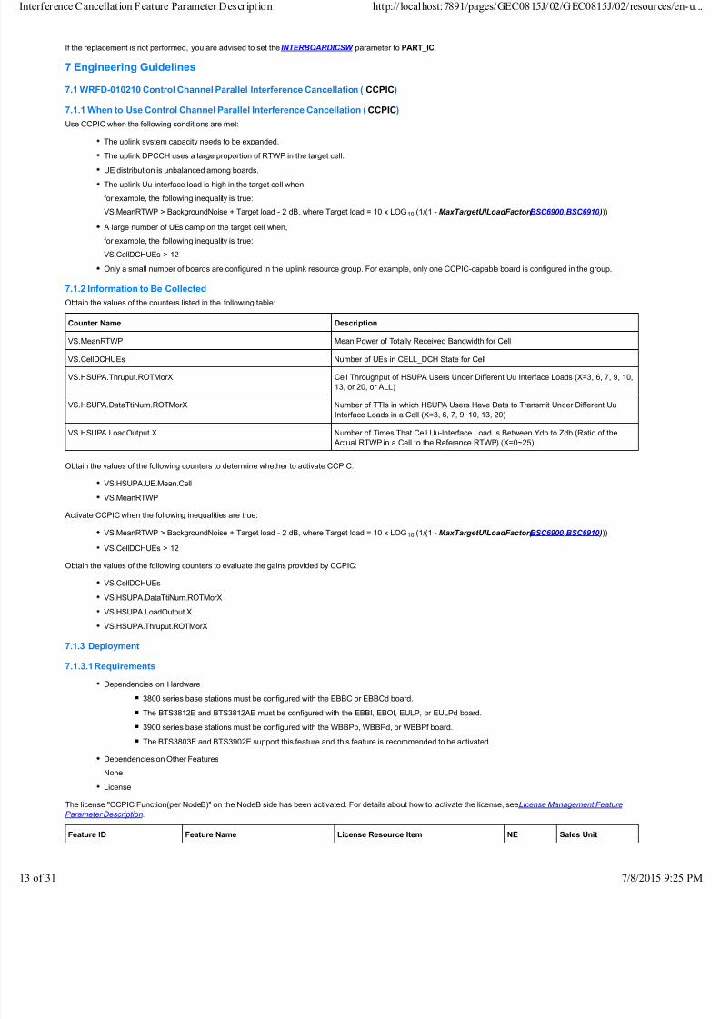
7.1.2 Information to Be Collected
Obtain the values of the counters listed in the following table:
Counter Name Description
VS.MeanRTWP Mean Power of Totally Received Bandwidth for Cell
VS.CellDCHUEs Number of UEs in CELL_DCH State for Cell
VS.HSUPA.Thruput.ROTMorX Cell Throughput of HSUPA Users Under Different Uu Interface Loads (X=3, 6, 7, 9, 10,
13, or 20, or ALL)
VS.HSUPA.DataTtiNum.ROTMorX Number of TTIs in which HSUPA Users Have Data to Transmit Under Different Uu
Interface Loads in a Cell (X=3, 6, 7, 9, 10, 13, 20)
VS.HSUPA.LoadOutput.X Number of Times That Cell Uu-lnterface Load Is Between Ydb to Zdb (Ratio of the
Actual RTWP in a Cell to the Reference RTWP) (X=0~25)
Obtain the values of the following counters to determine whether to activate CCPIC:
VS.HSUPA.UE.Mean.Cell
VS.MeanRTWP
Activate CCPIC when the following inequalities are true:
VS.MeanRTWP > BackgroundNoise + Target load - 2 dB, where Target load = 10 x LOG 10 (1/(1 - MaxTargetUlLoadFactor( BSC6900 ,BSC6910 )))
VS.CellDCHUEs > 12
Obtain the values of the following counters to evaluate the gains provided by CCPIC:
VS.CellDCHUEs
VS.HSUPA.DataTtiNum.ROTMorX
VS.HSUPA.LoadOutput.X
VS.HSUPA.Thruput.ROTMorX
7.1.3 Deployment
7.1.3.1 Requirements
Dependencies on Hardware
3800 series base stations must be configured with the EBBC or EBBCd board.
The BTS3812E and BTS3812AE must be configured with the EBBI, EBOI, EULP, or EULPd board.
3900 series base stations must be configured with the WBBPb, WBBPd, or WBBPf board.
The BTS3803E and BTS3902E support this feature and this feature is recommended to be activated.
Dependencies on Other Features
None
License
The license "CCPIC Function(per NodeB)" on the NodeB side has been activated. For details about how to activate the license, see License Management Feature
Parameter Description.
Feature ID Feature Name License Resource Item NE Sales Unit
erence Cancellation Feature Parameter Description http://localhost:7891/pages/GEC0815J/02/GEC0815J/02/resourc
31 7/8/2015

7/18/2019 Interference Cancellation Feature
http://slidepdf.com/reader/full/interference-cancellation-feature 14/31
Feature ID Feature Name License Resource Item NE Sales Unit
WRFD-010210 Control Channel Parallel Interference
Cancellation (CCPIC)
CCPIC Function(per NodeB) NodeB per NodeB
7.1.3.2 Data Preparation
None
7.1.3.3 Activation
CCPIC is automatically activated after the license that controls this feature is activated.
7.1.3.4 Activation ObservationRun the NodeB MML command DSP LICENSE to query whether the license that controls CCPIC has been activated. Figure 7-1 shows the query results.
Figure 7-1 Query results of the CCPIC license status
NOTE:
Observe the activation effect when there are a large number of UEs because CCPIC gains are obvious only in this scenario.
7.1.3.5 Deactivation
Deactivate the license that controls CCPIC.
7.1.4 Performance Monitoring
CCPIC performance can be monitored by the uplink system capacity and uplink load. The two items are measured by the counters listed in the following table:
Counter Name Description
VS.CellDCHUEs Number of UEs in CELL_DCH State for Cell
VS.HSUPA.Thruput.ROTMorX Cell Throughput of HSUPA Users Under Different Uu Interface Loads (X=3, 6, 7, 9, 10, 13, or
20)
VS.HSUPA.DataTtiNum.ROTMorX Number of TTIs in which HSUPA Users Have Data to Transmit Under Different Uu Interface
Loads in a Cell (X=3, 6, 7, 9, 10, 13, 20, or ALL)
VS.HSUPA.LoadOutput.X Number of Times That Cell Uu-lnterface Load Is Between Ydb to Zdb (Ratio of the Actual
RTWP in a Cell to the Reference RTWP) (X=0~25)
Uplink System Capacity
CCPIC can increase the uplink capacity for a cell when the cell load is high. The uplink cell capacity can be monitored by the average number of online UEs in the cell
or the uplink cell throughput as follows:
erence Cancellation Feature Parameter Description http://localhost:7891/pages/GEC0815J/02/GEC0815J/02/resourc
31 7/8/2015

7/18/2019 Interference Cancellation Feature
http://slidepdf.com/reader/full/interference-cancellation-feature 15/31
If existing UEs in the cell are not processing data and many other UEs attempt to access the cell when power-based admission control has been activated,
compare the value of VS.CellDCHUEs before and after feature activation to evaluate the feature gains. A sample scenario is when a large number of R99
UEs camp on the cell.
When a large amount of HSUPA data needs to be transmitted, compare the values of VS.HSUPA.Thruput.ROTMorX and VS.HSUPA.DataTtiNum.ROTMor
X before and after feature activation to monitor the feature gains. The expected result is that VS.HSUPA.Thruput.ROTMorX and
VS.HSUPA.Thruput.ROTMorX divided by VS.HSUPA.DataTtiNum.ROTMorX increase after feature activation where X = 10LOG 10(1/(1-
MaxTargetUlLoadFactor( BSC6900 ,BSC6910 ))).
Uplink Load
If the uplink cell capacity remains unchanged, CCPIC helps decrease the cell load. Compare the value of VS.HSUPA.LoadOutput.X before and after feature activation
to monitor the feature gains. The expected result is that the counter value decreases after feature activation.
7.1.5 Parameter Optimization
None
7.1.6 Troubleshooting
None
7.2 WRFD-140202 Control Channel Parallel Interference Cancellation (Phase 2)
7.2.1 When to Use Control Channel Parallel Interference Cancellation (Phase 2)
Use CCPIC (Phase 2) when the following conditions are met:
The uplink system capacity needs to be expanded.
The uplink DPCCH uses a large proportion of RTWP in the target cell.
The uplink Uu-interface load is high in the target cell when,
for example, the following inequality is true:VS.MeanRTWP > BackgroundNoise + Target load - 2 dB, where Target load = 10 x LOG 10 (1/(1 - MaxTargetUlLoadFactor( BSC6900 ,BSC6910 )))
A large number of UEs camp on the target cell when,
for example, the following inequality is true:
VS.CellDCHUEs > 12
7.2.2 Information to Be Collected
The information to be collected for CCPIC(Phase 2) is the same as that for CCPIC. For details, see section 7.1.2 Information to Be Collected.
7.2.3 Deployment
7.2.3.1 Requirements
Dependencies on Hardware
The 3900 series base stations support this feature and must be configured with the WBBPd or WBBPf board.
To support inter-board IC, the WBBPd or WBBPf board must be configured for the uplink resource group that supports inter-board IC. In addition, at leastone WBBPd or WBBPf board must be configured in slot 2 or 3.
UEs with their data channels carried on a WBBPa or WBBPb board of 3900 series base stations can share the IC gains from a WBBPd or WBBPf board
only when the following conditions are met:
The WBBPa or WBBPb board and the WBBPd or WBBPf board are installed in one BBU to form an uplink resource group.
INTERBOARDICSW is set to FULL_IC.
Inter-board data channels are configured for the UEs to set up control channels on the WBBPd or WBBPf board.
NOTE:
Replace the WBBPa or WBBPb board with a WBBPd or WBBPf board to maximize the gains provided by CCPIC (Phase 2). The reason is as follows:
Assume that a WBBPa or WBBPb board and a WBBPd or WBBPf board form an uplink resource group. When the INTERBOARDICSW parameter is set to
FULL_IC for a WBBPa or WBBPb board to benefit from CCPIC (Phase 2) gains provided by a WBBPd or WBBPf board, UEs whose data channels are
carried on the WBBPa or WBBPb board must set up DPCCHs on the WBBPd or WBBPf board for power control purposes. In addition, UEs whose downlink
services are carried on HSDPA channels must set up another HS-DPCCH on the WBBPd or WBBPf board. The new channels consume extra resources,
which reduces the total number of users supported by the system and decreases the access success rate.
The BTS3803E supports this feature.
The BTS3902E does not support this feature.
Dependencies on Other Features
WRFD-010210 Control Channel Parallel Interference Cancellation (CCPIC) must be activated.
License
The license "Control Channel Parallel Interference Cancellation (Phase 2)(per NodeB) " on the NodeB side has been activated. For details about how to
activate the license, see License Management Feature Parameter Description.
Feature ID Feature Name License Control Item NE Sales Unit
WRFD-140202 Control Channel Parallel Interference
Cancellation (Phase 2)
Control Channel Parallel Interference
Cancellation (Phase 2)(per NodeB)
NodeB Per NodeB
erence Cancellation Feature Parameter Description http://localhost:7891/pages/GEC0815J/02/GEC0815J/02/resourc
31 7/8/2015

7/18/2019 Interference Cancellation Feature
http://slidepdf.com/reader/full/interference-cancellation-feature 16/31
7.2.3.2 Data Preparation
None
7.2.3.3 Activation
Using MML Commands
After the license controlling CCPIC (Phase 2) is activated, CCPIC (Phase 2) automatically takes effect on WBBPd and WBBPf boards. For WBBPa and WBBPb
boards, activate CCPIC (Phase 2) in different scenarios listed in Table 7-1.
Table 7-1 Activation scenarios
Scenario Does a WBBPa or WBBPb Need to Share IC Gains? Value of the Parameter Inter-board cancellation gain switch
between the WBBPa and WBBPb boards
Scenario 1 No PART_IC(Old board can not share IC gain)
Scenario 2 No FULL_IC(All board can share IC gain)
Scenario 3 Yes PART_IC(Old board can not share IC gain)
Scenario 4 Yes FULL_IC(All board can share IC gain)
NOTE:
Run the NodeB MML command LST NODEBICMODE to query the value of the Inter-board cancellation gain switch between the WBBPa and WBBPb boards
parameter.
If HSUPA UL IC or Turbo IC has been activated before CCPIC (Phase 2), the value for Inter-board cancellation gain switch between the WBBPa and WBBPb
boards remains unchanged after CCPIC (Phase 2) is activated.
If HSUPA UL IC or Turbo IC is not activated before CCPIC (Phase 2), it is recommended that Inter-board cancellation gain switch between the WBBPa and
WBBPb boards be set to PART_IC(Old board can not share IC gain) after CCPIC (Phase 2) is activated.
Scenario 1:
No configuration is required.
Scenario 2:
Run the NodeB MML command SET NODEBICMODE. In this step, set Inter-board cancellation gain switch between the WBBPa and WBBPb boards
to PART_IC(Old board can not share IC gain).
NOTE:
Running the SET NODEBICMODE command may cause call drops on UEs whose data is carried over WBBPa or WBBPb boards. Therefore, it is recommended that
you run this command when traffic is light, for example, early in the morning.
Scenario 3:
Run the NodeB MML command LST NODEBRESALLOCRULE to check whether the Auto Rebuild Cell Switch is turned on.
If the switch is turned on, run the NodeB MML command SET NODEBICMODE and set Inter-board cancellation gain switch between theWBBPa and WBBPb boards to FULL_IC(All board can share IC gain).
If the switch is turned off, do as follows:
Run the NodeB MML command SET NODEBICMODE and set Inter-board cancellation gain switch between the WBBPa and WBBPb boards to
FULL_IC(All board can share IC gain).
1.
(Optional) Run the NodeB MML command SET NODEBRESALLOCRULE. In this step, set Auto Rebuild Cell Switch to ON(ON) and set Cs User
Number Threshold and Ps User Number Threshold to appropriate values. If the number of CS users or PS CELL_DCH users in the downlink resource
group is equal to or less than the corresponding threshold, the local cell is automatically reestablished.
2.
NOTE:
Running the SET NODEBICMODE command may cause call drops on UEs whose data is carried over WBBPa or WBBPb boards. Therefore, it is
recommended that you run this command when traffic is light, for example, early in the morning.
It is recommended that you perform step 2 when the Auto Rebuild Cell Switch is turned off. The reason is as follows: WBBPa and WBBPb boards cannot
share IC gains if the board status changes in an uplink resource group and can share IC gains again after the local cell is reestablished.
Scenario 4:
Run the NodeB MML command LST NODEBRESALLOCRULE and check whether the Auto Rebuild Cell Switch is turned on.
If the switch is turned on, no configuration is required. However, WBBPa and WBBPb boards can share IC gains only after the local cell is
reestablished.
If the switch is turned off, run the NodeB MML command SET NODEBRESALLOCRULE. Then, set Auto Rebuild Cell Switch to ON(ON) and
set Cs User Number Threshold and Ps User Number Threshold to appropriate values. If the number of CS users or PS CELL_DCH users in
the downlink resource group is equal to or less than the corresponding threshold, the local cell is automatically reestablished.
NOTE:
It is recommended that the Auto Rebuild Cell Switch be turned on. The reason is as follows: WBBPa and WBBPb boards cannot share IC gains if the
board status changes in an uplink resource group and can share IC gains again after the local cell is reestablished.
MML Command Examples
//Activating CCPIC (Phase 2)
erence Cancellation Feature Parameter Description http://localhost:7891/pages/GEC0815J/02/GEC0815J/02/resourc
31 7/8/2015

7/18/2019 Interference Cancellation Feature
http://slidepdf.com/reader/full/interference-cancellation-feature 17/31
//Scenario 1:
//No configuration is required.
//Scenario 2SET NODEBICMODE: INTERBOARDICSW =PART_IC;
//Scenario 3
SET NODEBICMODE: INTERBOARDICSW =FULL_IC;
LST NODEBRESALLOCRULE:;//If the Auto Rebuild Cell Switch is turned off:
SET NODEBRESALLOCRULE: SW=ON, CSUSERNUM=0, PSUSERNUM=0;
//Scenario 4
LST NODEBRESALLOCRULE:;//If the Auto Rebuild Cell Switch is turned off:SET NODEBRESALLOCRULE: SW=ON, CSUSERNUM=0, PSUSERNUM=0;
Activation (Using the CME)
NOTE:
When configuring the CCPIC (Phase 2) feature on the CME, perform a single configuration first, and then perform a batch modification if required.
Configure the parameters of a single object before a batch modification. Perform a batch modification before logging out of the parameter setting interface.
Configure a single object (such as a cell) on the CME.
Set parameters on the CME according to the operation sequence in Table 7-2 for scenario 2 , Table 7-3 for scenario 3, or Table 7-4 for scenario 4. For
instructions on how to perform the CME single configuration, see CME Single Configuration Operation Guide.
1.
(Optional) Modify objects in batches on the CME. (CME batch modification center)
To modify objects in batches, click on the CME to start the batch modification wizard. For instructions on how to perform a batch modification throughthe CME batch modification center, press F1 on the wizard interface to obtain online help.
2.
NOTE:
In scenario 1, CCPIC (Phase 2) is automatically activated after the license that controls this feature is activated.
Table 7-2 Configuring parameters on the CME (scenario 2)
SN MO NE Parameter Name Parameter ID Configurable in CME
Batch Modification
Center
1 NODEBALGPARA NodeB Inter-board cancellation gain switch
between the WBBPa and WBBPb
boards
NOTE:
Set this parameter to PART_IC(Oldboard can not share IC gain).
INTERBOARDICSW Yes
Table 7-3 Configuring parameters on the CME (scenario 3)
SN MO NE Parameter Name Parameter ID Configurable in CME
Batch Modification
Center
1 NODEBALGPARA NodeB Inter-board cancellation gain switch
between the WBBPa and WBBPb
boards
NOTE:
Set this parameter
to FULL_IC(All board can share IC
gain).
INTERBOARDICSW Yes
2 NODEBRESALLOCRULE NodeB Auto Rebuild Cell Switch
NOTE:
Set this parameter to ON(ON).
SW Yes
Cs User Number Threshold CSUSERNUM
Ps User Number Threshold PSUSERNUM
Table 7-4 Configuring parameters on the CME (scenario 4)
SN MO NE Parameter Name Parameter ID Configurable in CME
Batch Modification
erence Cancellation Feature Parameter Description http://localhost:7891/pages/GEC0815J/02/GEC0815J/02/resourc
31 7/8/2015

7/18/2019 Interference Cancellation Feature
http://slidepdf.com/reader/full/interference-cancellation-feature 18/31
Center
1 NODEBRESALLOCRULE NodeB Auto Rebuild Cell Switch
NOTE:
Set this parameter to ON(ON).
SW Yes
Cs User Number Threshold CSUSERNUM
Ps User Number Threshold PSUSERNUM
7.2.3.4 Activation Observation
Check whether CCPIC (Phase 2) has been activated using the RNC or NodeB LMT. If the base station is configured with the RRU3801C, the following verification
modes do not apply.
NOTE:
Observe the activation effect only when there are a large number of UEs because CCPIC (Phase 2) gains are obvious only in this scenario.
Using the RNC LMT:
On the RNC LMT, click Monitor , choose Cell Performance Monitoring > RTWP, enter the cell ID, and click Submit.1.
Check whether a valid value is displayed for Cell measured RTWP After First Stage Interference Cancellation.
Expected result:
A valid value is displayed, indicating that the CCPIC (Phase 2) feature is functioning properly. When there are a large number of UEs, Cell measured
RTWP After First Stage Interference Cancellation is smaller than Cell Measured RTWP. The RTWP decrease further indicates that this feature has
been activated. Figure 7-2 shows the RTWP monitoring result displayed on the RNC LMT.
Figure 7-2 Cell-level RTWP monitoring on the RNC LMT
2.
Using the NodeB LMT:
On the NodeB LMT, click Maintenance, choose Service > Realtime Specific Monitoring > Cell RTWP.1.
Check whether a valid value is displayed for Cell measured RTWP After First Stage Interference Cancellation.
Expected result:
A valid value is displayed, indicating that the CCPIC (Phase 2) feature is functioning properly. When there are a large number of UEs, Cell measured
RTWP After First Stage Interference Cancellation is smaller than Cell Measured RTWP. The RTWP decrease further indicates that this feature has
been activated. Figure 7-3 shows the RTWP monitoring result displayed on the NodeB LMT.
Figure 7-3 Cell-level RTWP monitoring on the NodeB LMT
2.
erence Cancellation Feature Parameter Description http://localhost:7891/pages/GEC0815J/02/GEC0815J/02/resourc
31 7/8/2015

7/18/2019 Interference Cancellation Feature
http://slidepdf.com/reader/full/interference-cancellation-feature 19/31
7.2.3.5 Deactivation
Deactivate the license that controls CCPIC (Phase 2).
7.2.4 Performance Monitoring
CPIC (Phase 2) performance can be monitored by the IC efficiency, uplink system capacity, and uplink load. The three items are measured by the counters listed in the
following table:
Counter Name Description
VS.CellDCHUEs Number of UEs in CELL_DCH State for Cell
VS.HSUPA.Thruput.ROTMorX Cell Throughput of HSUPA Users Under Different Uu Interface Loads (X=3, 6, 7, 9, 10,
13, or 20, or ALL)
VS.HSUPA.DataTtiNum.ROTMorX Number of TTIs in which HSUPA Users Have Data to Transmit Under Different Uu
Interface Loads in a Cell (X=3, 6, 7, 9, 10, 13, 20)
VS.FirstStageIcEff.Mean Average Value of First-Stage IC Efficiency
VS.FirstStageIcEff.Max Maximum Value of First-Stage IC Efficiency
VS.HSUPA.LoadOutput.X Number of Times That Cell Uu-lnterface Load Is Between Ydb to Zdb
(Ratio of the Actual RTWP in a Cell to the Reference RTWP) (X=0~25)
IC Efficiency
After feature activation, the values of the VS.FirstStageIcEff.Mean and VS.FirstStageIcEff.Max counters are not 0.
Uplink System Capacity
CCPIC (Phase 2) can increase the uplink capacity for a cell when the cell load is high. The uplink cell capacity can be monitored by the average number of online UEs
in the cell or the uplink cell throughput as described in the following:
If existing UEs in the cell are not processing data and many other UEs attempt to access the cell when power-based admission control has been activated, compare
the value of VS.CellDCHUEs before and after feature activation to evaluate the feature gains. A sample scenario is when a large number of R99 UEs camp on the cell.
When a large amount of HSUPA data needs to be transmitted, compare the values of VS.HSUPA.Thruput.ROTMorX and VS.HSUPA.DataTtiNum.ROTMorX before
and after feature activation to monitor the feature gains. The expected result is that VS.HSUPA.Thruput.ROTMorX and VS.HSUPA.Thruput.ROTMorX divided by
VS.HSUPA.DataTtiNum.ROTMorX increase after feature activation where X = 10LOG10(1/(1-MaxTargetUlLoadFactor( BSC6900 ,BSC6910 ))).
Uplink Load
If the uplink cell capacity remains unchanged, CCPIC (Phase 2) helps decrease the uplink cell load. Compare the value of VS.HSUPA.LoadOutput.X before and after
feature activation to monitor the feature gains. The expected result is that the counter value decreases after feature activation.
NOTE:
Use the following formula to calculate the efficiency of the first-stage IC for a cell:
Efficiency of the first-stage IC = (RTWP measured before IC - RTWP measured after first-stage IC)/RTWP measured before IC
7.2.5 Parameter Optimization
If the NodeB uplink resource group is not configured with a WBBPa or WBBPb board, parameter optimization is not needed.
If the NodeB uplink resource group is configured with a WBBPa or WBBPb board and INTERBOARDICSW is set to PART_IC, you can change INTERBOARDICSW to
FULL_IC to further increase Uu interface capacity. However, this change may reduce the number of UEs to be admitted. Do not make this change when the number of
UEs to be admitted is limited. To increase the uplink system capacity without limiting the UE number, replace the WBBPa or WBBPb board with a WBBPd or WBBPf
board. If the replacement is not performed, you are advised to set the INTERBOARDICSW parameter to PART_IC.
7.2.6 Troubleshooting
None
7.3 WRFD-010691 HSUPA UL Interference Cancellation
7.3.1 When to Use HSUPA UL Interference Cancellation
Use HSUPA UL IC when the following conditions are met:
The uplink Uu-interface load is high in the target cell when,
for example, the following inequality is true:
VS.MeanRTWP > BackgroundNoise + Target load - 2 dB, where Target load = 10 x LOG 10 (1/(1 - MaxTargetUlLoadFactor( BSC6900 ,BSC6910 )))
A small number of HSUPA UEs camp on the target cell when,
for example, the following inequality is true:
VS.HSUPA.MeanBitRate.WithData > a value within the range of 100 kbit/s to 400 kbit/s
7.3.2 Information to Be Collected
Obtain the values of the counters listed in the following table:
erence Cancellation Feature Parameter Description http://localhost:7891/pages/GEC0815J/02/GEC0815J/02/resourc
31 7/8/2015

7/18/2019 Interference Cancellation Feature
http://slidepdf.com/reader/full/interference-cancellation-feature 20/31
Counter Name Description
VS.MeanRTWP Mean Power of Totally Received Bandwidth for Cell
VS.HSUPA.UE.Mean.Cell Average Number of HSUPA UEs in a Cell
VS.HSUPA.MeanBitRate.WithData Average Throughput of HSUPA Users in a Cell when Data Is Transmitted
VS.CellDCHUEs Number of UEs in CELL_DCH State for Cell
VS.HSUPA.Thruput.ROTMorX Cell Throughput of HSUPA Users Under Different Uu Interface Loads (X=3, 6, 7,
9, 10, 13, or 20, or ALL)
VS.HSUPA.DataTtiNum.ROTMorX Number of TTIs in which HSUPA Users Have Data to Transmit Under Different UuInterface Loads in a Cell (X=3, 6, 7, 9, 10, 13, 20)
VS.HSUPA.LoadOutput.X Number of Times That Cell Uu-lnterface Load Is Between Ydb to Zdb (Ratio of
the Actual RTWP in a Cell to the Reference RTWP) (X=0~25)
Obtain the values of the following counters to determine whether to activate HSUPA UL IC:
VS.MeanRTWP
VS.HSUPA.UE.Mean.Cell
VS.HSUPA.MeanBitRate.WithData
Obtain the values of the following counters to evaluate the gains provided by HSUPA UL IC:
VS.HSUPA.Thruput.ROTMorX
VS.CellDCHUEs
VS.HSUPA.DataTtiNum.ROTMorX
VS.HSUPA.LoadOutput.X
VS.HSUPA.Thruput
7.3.3 Deployment
7.3.3.1 Requirements
Dependencies on Hardware
Dependencies on RNC Hardware
None
Dependencies on NodeB Hardware
3800 series base stations must be configured with EBBCd boards, which support E-DPDCH IC and inter-board IC. If two EBBCd boards are
configured, do not enable inter-board IC for both boards. Otherwise, only one of the EBBCd boards can support E-DPDCH IC.
The BTS3812E and BTS3812AE must be configured with the EULPd board, and downlink services of the target cell cannot be established on
the HBBI or HDLP/NDLP board. The BTS3812E and BTS3812AE do not support inter-board IC.
3900 series base stations must be configured with the WBBPd or WBBPf board. At least one WBBPd or WBBPf board must be configured in
slot 2 or 3 to support inter-board IC. 3900 series base stations support inter-board E-DPDCH IC. Whether the WBBPa or WBBPb board can
benefit from other boards depends on the setting of the INTERBOARDICSW parameter.
The BTS3803E and BTS3902E support this feature.
UEs with their data channels carried on a WBBPa or WBBPb board of 3900 series base stations can share the IC gains from a WBBPd or
WBBPf board only when the following conditions are met:
The WBBPa or WBBPb board and the WBBPd or WBBPf board are installed in one BBU to form an uplink resource group.
INTERBOARDICSW is set to FULL_IC.
Inter-board data channels are configured for the UEs to set up control channels on the WBBPd or WBBPf board.
Dependencies on Other Features
WRFD-010612 HSUPA Introduction Package
License
The license "IC Function(per Cell)" on the NodeB side has been activated. For details about how to activate the license, see License Management Feature
Parameter Description.
Feature ID Feature Name License Resource Item NE Sales Unit
WRFD-010691 HSUPA UL Interference
Cancellation
IC Function(per Cell) NodeB Per cell
Other Prerequisites
The NodeB software version must be RAN12.0 or later.
The BSC6900 software version must be RAN12.0 or later.
7.3.3.2 Data Preparation
None
erence Cancellation Feature Parameter Description http://localhost:7891/pages/GEC0815J/02/GEC0815J/02/resourc
31 7/8/2015

7/18/2019 Interference Cancellation Feature
http://slidepdf.com/reader/full/interference-cancellation-feature 21/31
7.3.3.3 Activation
Using MML Commands
Scenario 1: The WBBPa/WBBPb board is configured in the uplink resource group and Inter-board cancellation gain switch between the WBBPa and WBBPb
boards is set to FULL_IC(All board can share IC gain). In scenario 1, perform the following steps:
For the BTS3812AE, BTS3812E, and DBS3800
Run the NodeB MML command MOD LOCELL to modify the local cell. In this step, set IC to TRUE(TRUE).1.
Run the NodeB MML command SET RESALLOCRULE. In this step, set Auto Rebuild Cell Switch to ON(ON) and set Cs User Number
Threshold and Ps User Number Threshold to appropriate values. When the number of CS UEs in a downlink resource group is smaller than
or equal to the value of Cs User Number Threshold and the number of PS UEs in the CELL_DCH state is smaller than or equal to the value of
Ps User Number Threshold, local cells are automatically reestablished.
2.
For the 3900 series base stations, BTS3902E, and BTS3803E
Run the NodeB MML command MOD ULOCELL to modify the local cell. In this step, set IC to TRUE(TRUE).1.
Run the NodeB MML command SET NODEBRESALLOCRULE. In this step, set Auto Rebuild Cell Switch to ON(ON) and set Cs User
Number Threshold and Ps User Number Threshold to appropriate values. When the number of CS UEs in a downlink resource group is
smaller than or equal to the value of Cs User Number Threshold and the number of PS UEs in the CELL_DCH state is smaller than or equal
to the value of Ps User Number Threshold, local cells are automatically reestablished.
2.
Scenario 2: The WBBPa/WBBPb board is not configured in the uplink resource group; alternatively the WBBPa/WBBPb board is configured in the uplink resource
group and Inter-board cancellation gain switch between the WBBPa and WBBPb boards is set to PART_IC(Old board can not share IC gain). In scenario 2,
perform the following steps:
For the BTS3812AE, BTS3812E, and DBS3800:
Run the NodeB MML command MOD LOCELL to modify the local cell. In this step, set IC to TRUE(TRUE).
For the 3900 series base stations, BTS3902E, and BTS3803E:
Run the NodeB MML command MOD ULOCELL to modify the local cell. In this step, set IC to TRUE(TRUE).
NOTE:
Run the NodeB MML command LST NODEBICMODE to query the value of the Inter-board cancellation gain switch between the WBBPa and WBBPb
boards parameter.
If CCPIC (Phase 2) has been activated before HSUPA UL IC, the value for Inter-board cancellation gain switch between the WBBPa and WBBPb
boards remains unchanged after HSUPA UL IC is activated.
If CCPIC (Phase 2) has been activated before HSUPA UL IC, it is recommended that Inter-board cancellation gain switch between the WBBPa and
WBBPb boards be set to PART_IC(Old board can not share IC gain) after HSUPA UL IC is activated.
MML Command Examples
//Activating HSUPA UL Interference Cancellation
//For the BTS3812AE, BTS3812E, and DBS3800
//In scenario 1:
MOD LOCELL: LOCELL=1, SECT=LOCAL_SECTOR, IC_MODE=TRUE;
SET RESALLOCRULE: SW=ON, CSUSERNUM=0, PSUSERNUM=0;
//In scenario 2:
MOD LOCELL: LOCELL=1, SECT=LOCAL_SECTOR, IC_MODE=TRUE;
//For the 3900 series base stations, BTS3902E, and BTS3803E
//In scenario 1:
MOD ULOCELL: ULOCELLID=1, LOCELLTYPE=NORMAL_CELL, ICMODE=TRUE;
SET NODEBRESALLOCRULE: SW=ON, CSUSERNUM=0, PSUSERNUM=0;
//In scenario 2:
MOD ULOCELL: ULOCELLID=1, LOCELLTYPE=NORMAL_CELL, ICMODE=TRUE;
Activation (Using the CME)
NOTE:When configuring the HSUPA UL IC feature on the CME, perform a single configuration first, and then perform a batch modification if required.
Configure the parameters of a single object before a batch modification. Perform a batch modification before logging out of the parameter setting interface.
Configure a single object (such as a cell) on the CME.
Set parameters on the CME according to the operation sequence in Table 7-5 for scenario 1 or Table 7-6 for scenario 2. For instructions on how to perform
the CME single configuration, see CME Single Configuration Operation Guide.
1.
(Optional) Modify objects in batches on the CME. (CME batch modification center)
To modify objects in batches, click on the CME to start the batch modification wizard. For instructions on how to perform a batch modification through
the CME batch modification center, press F1 on the wizard interface to obtain online help.
2.
Table 7-5 Configuring parameters on the CME (scenario 1)
SN MO NE Parameter Name Parameter ID Configurable in CME
erence Cancellation Feature Parameter Description http://localhost:7891/pages/GEC0815J/02/GEC0815J/02/resourc
31 7/8/2015

7/18/2019 Interference Cancellation Feature
http://slidepdf.com/reader/full/interference-cancellation-feature 22/31
Batch Modification
Center
1 For the BTS3812AE,
BTS3812E, and DBS3800:
LOCELL
NodeB IC
NOTE:
Set this parameter to TRUE(TRUE).
IC_MODE Yes
For the 3900 series base
stations, BTS3902E, and
BTS3803E: ULOCELL
NodeB IC
NOTE:
Set this parameter to TRUE(TRUE).
ICMODE Yes
2 For the BTS3812AE,
BTS3812E, and DBS3800:
RESALLOCRULE
For the 3900 series base
stations, BTS3902E, and
BTS3803E:
NODEBRESALLOCRULE
NodeB Auto Rebuild Cell Switch
NOTE
Set this parameter to ON(ON).
SW Yes
Cs User Number Threshold CSUSERNUM
Ps User Number Threshold PSUSERNUM
Table 7-6 Configuring parameters on the CME (scenario 2)
SN MO NE Parameter Name Parameter ID Configurable in CME
Batch Modification
Center
1 For the BTS3812AE,
BTS3812E, and DBS3800:LOCELL
NodeB IC
NOTE:
Set this parameter to TRUE(TRUE).
IC_MODE Yes
For the 3900 series base
stations, BTS3902E, and
BTS3803E:
ULOCELL
NodeB IC
NOTE:
Set this parameter to TRUE(TRUE).
ICMODE Yes
7.3.3.4 Activation Observation
Check whether the HSUPA UL Interference Cancellation feature has been activated using the RNC or NodeB LMT. The following steps are performed on the NodeB
LMT:
Query the status of a local cell.
For the BTS3812AE, BTS3812E, and DBS3800, run the NodeB MML command DSP LOCELL to query the status of a local cell.
For the 3900 series base stations, BTS3902E, and BTS3803E, run the NodeB MML command DSP ULOCELL to query the status of a local cell.
Expected result: The value of IC MODE is ENABLED.
1.
Select Service > Realtime Specific Monitoring > Cell RTWP from the navigation tree in Maintenance tab on the NodeB LMT. In Figure 7-4 the column
1-3 indicates the state of this feature before activation, and the column 1-4 indicates the state of this feature after activation. If the value of column 1-4 is
less than the value of column 1-3, the feature has been activated.
Figure 7-4 Cell RTWP 1
2.
7.3.3.5 Deactivation
Using MML Commands
For the BTS3812AE, BTS3812E, and DBS3800
Run the NodeB MML command MOD LOCELL to modify the local cell. In this step, set IC to FALSE.
For the 3900 series base stations, BTS3902E, and BTS3803E
Run the NodeB MML command MOD ULOCELL to modify the local cell. In this step, set IC to FALSE.
NOTE:
If the WBBPa/WBBPb board is configured in the uplink resource group and Inter-board cancellation gain switch between the WBBPa and WBBPb boards is set to
erence Cancellation Feature Parameter Description http://localhost:7891/pages/GEC0815J/02/GEC0815J/02/resourc
31 7/8/2015

7/18/2019 Interference Cancellation Feature
http://slidepdf.com/reader/full/interference-cancellation-feature 23/31
FULL_IC, deactivating HSUPA UL Interference Cancellation may cause UEs admitted on the WBBPa/WBBPb board to experience call drops.
MML Command Examples
//Deactivating HSUPA UL Interference Cancellation
//For the BTS3812AE, BTS3812E, and DBS3800:
MOD LOCELL: LOCELL=1, SECT=LOCAL_SECTOR, IC_MODE=FALSE;
//For the 3900 series base stations, BTS3902E, and BTS3803E:
MOD ULOCELL: ULOCELLID=1, LOCELLTYPE=NORMAL_CELL, ICMODE=FALSE;
Deactivation (Using the CME)
NOTE:
When configuring the HSUPA UL IC feature on the CME, perform a single configuration first, and then perform a batch modification if required.
Configure the parameters of a single object before a batch modification. Perform a batch modification before logging out of the parameter setting interface.
Configure a single object (such as a cell) on the CME.
Set parameters on the CME according to the operation sequence in Table 7-7. For instructions on how to perform the CME single configuration, see CME
Single Configuration Operation Guide.
1.
(Optional) Modify objects in batches on the CME. (CME batch modification center)
To modify objects in batches, click on the CME to start the batch modification wizard. For instructions on how to perform a batch modification through
the CME batch modification center, press F1 on the wizard interface to obtain online help.
2.
Table 7-7 Configuring parameters on the CME
SN MO NE Parameter Name Parameter ID Configurable in CME
Batch Modification
Center
1 For the BTS3812AE, BTS3812E,
and DBS3800: LOCELL
NodeB IC
NOTE:
Set this parameter to FALSE(FALSE).
IC_MODE Yes
For the 3900 series base stations,
BTS3902E, and BTS3803E:
ULOCELL
NodeB IC
NOTE:
Set this parameter to FALSE(FALSE).
ICMODE Yes
7.3.4 Performance Monitoring
HSUPA UL IC performance can be monitored by the IC efficiency, uplink system capacity, and uplink load. The three items are measured by the counters listed in the
following table:
Counter Name Description
VS.CellDCHUEs Number of UEs in CELL_DCH State for Cell
VS.HSUPA.Thruput.ROTMorX Cell Throughput of HSUPA Users Under Different Uu Interface Loads (X=3, 6, 7, 9, 10,
13, or 20, or ALL)
VS.HSUPA.DataTtiNum.ROTMorX Number of TTIs in which HSUPA Users Have Data to Transmit Under Different Uu
Interface Loads in a Cell (X=3, 6, 7, 9, 10, 13, 20)
VS.HSUPA.Ic.MeanEff Average IC Efficiency in a Cell
VS.HSUPA.Ic.MaxEff Maximum IC Efficiency in a Cell
VS.HSUPA.LoadOutput.X Number of Times That Cell Uu-Interface Load Is Between Ydb to Zdb (Ratio of the Actual
RTWP in a Cell to the Reference RTWP) (X=0~25)
IC Efficiency
After feature activation, the values of the VS.HSUPA.Ic.MeanEff and VS.HSUPA.Ic.MaxEff counters are not 0.
Uplink System Capacity
HSUPA UL IC can increase the uplink capacity for a cell if the cell load is high. The uplink cell capacity can be monitored by the average number of online UEs in the
cell or the uplink cell throughput as described in the following:
If existing UEs in the cell are not processing data and many other UEs attempt to access the cell when power-based admission control has been activated,
compare the value of VS.CellDCHUEs before and after feature activation to evaluate the feature gains. A sample scenario is when a large number of R99
UEs and a small number of HSUPA UEs co-exist in the cell.
When a large amount of HSUPA data needs to be transmitted, compare the values of VS.HSUPA.Thruput.ROTMorX and
VS.HSUPA.DataTtiNum.ROTMorX before and after feature activation to monitor the feature gains. The expected result is that
VS.HSUPA.Thruput.ROTMorX and VS.HSUPA.Thruput.ROTMorX divided by VS.HSUPA.DataTtiNum.ROTMorX increase after feature activation where X =
10LOG10(1/(1-MaxTargetUlLoadFactor( BSC6900 ,BSC6910 ))).
erence Cancellation Feature Parameter Description http://localhost:7891/pages/GEC0815J/02/GEC0815J/02/resourc
31 7/8/2015

7/18/2019 Interference Cancellation Feature
http://slidepdf.com/reader/full/interference-cancellation-feature 24/31
Uplink Load
If the uplink cell capacity remains unchanged, HSUPA UL IC helps decrease the uplink cell load. Compare the value of VS.HSUPA.LoadOutput.X before and after
feature activation to monitor the feature gains. The expected result is that the counter value decreases after feature activation.
NOTE:
Use the following formula to calculate the IC efficiency for a cell:
IC efficiency = (RTWP measured before IC - RTWP measured after final IC)/RTWP measured before IC
7.3.5 Parameter Optimization
None
7.3.6 Troubleshooting
None
7.4 WRFD-150206 Turbo IC
7.4.1 When to Use Turbo IC
Use Turbo IC when the following conditions are met:
The uplink Uu-interface load is high in the target cell when,
for example, the following inequality is true:
VS.MeanRTWP > BackgroundNoise + Target load - 2 dB, where Target load = 10 x LOG 10 (1/(1 - MaxTargetUlLoadFactor( BSC6900 ,BSC6910 )))
HSUPA 2 ms TTI UEs with continuous data transmission account for a large proportion when, for example, the following inequality is true:
VS.HSUPA.UE.Mean.TTI2 ms/VS.CellDCHUEs > 0.5
Alternatively, there are high-speed HSUPA 2 ms TTI UEs when, for example, the following inequality is true:VS.HSUPA.TTI2 msUserNumber.2 + VS.HSUPA.TTI2 msUserNumber.3 + VS.HSUPA.TTI2 msUserNumber.4 + VS.HSUPA.TTI2 msUserNumber.5 > 1
7.4.2 Information to Be Collected
Obtain the values of the counters listed in the following table:
Counter Name Description
VS.MeanRTWP Mean Power of Totally Received Bandwidth for Cell
VS.HSUPA.TTI2msUserNumber.X Average Number of 2 ms TTI HSUPA Users at Different Rates in a Cell Within a
Measurement Period (X=0~5)
VS.CellDCHUEs Number of UEs in CELL_DCH State for Cell
VS.HSUPA.UE.Mean.TTI2ms Average Number of HSUPA 2 ms TTI UEs in a Cell
VS.HSUPA.Thruput.ROTMorX Cell Throughput of HSUPA Users Under Different Uu Interface Loads (X=3, 6, 7, 9, 10, 13,
or 20, or ALL)
VS.HSUPA.DataTtiNum.ROTMorX Number of TTIs in which HSUPA Users Have Data to Transmit Under Different Uu
Interface Loads in a Cell (X=3, 6, 7, 9, 10, 13, 20)
VS.HSUPA.Ic.MeanEff Average IC Efficiency in a Cell
VS.HSUPA.Ic.MaxEff Maximum IC Efficiency in a Cell
VS.HSUPA.LoadOutput.X Number of Times That Cell Uu-lnterface Load Is Between Ydb to Zdb (Ratio of the Actual
RTWP in a Cell to the Reference RTWP) (X=0~25)
Obtain the values of the following counters to determine whether to activate Turbo IC:
VS.CellDCHUEs
VS.HSUPA.TTI2msUserNumber.X
VS.HSUPA.UE.Mean.TTI2 ms
VS.MeanRTWP
Obtain the values of the following counters to evaluate the gains provided by Turbo IC:
VS.CellDCHUEs
VS.HSUPA.DataTtiNum.ROTMorX
VS.HSUPA.Ic.MaxEff
VS.HSUPA.Ic.MeanEff
VS.HSUPA.LoadOutput.X
VS.HSUPA.Thruput.ROTMorX
7.4.3 Deployment
7.4.3.1 Requirements
erence Cancellation Feature Parameter Description http://localhost:7891/pages/GEC0815J/02/GEC0815J/02/resourc
31 7/8/2015

7/18/2019 Interference Cancellation Feature
http://slidepdf.com/reader/full/interference-cancellation-feature 25/31
Dependencies on Hardware
3900 series base stations configured with at least one WBBPf board in the uplink resource group. At least one WBBPd or WBBPf board must be configured
in slot 2 or 3 to support inter-board IC. All boards in the uplink resource group must be configured as WBBPf boards to support inter-board Turbo IC.
The BTS3803E supports this feature.
UEs with their data channels carried on a WBBPa or WBBPb board of 3900 series base stations. can share the IC gains from a WBBPd or WBBPf board
only when the following conditions are met:
The WBBPa or WBBPb board and the WBBPd or WBBPf board are installed in one BBU to form an uplink resource group.
INTERBOARDICSW is set to FULL_IC.
Inter-board data channels are configured for the UEs to set up control channels on the WBBPd or WBBPf board.
BTS3803E supports this feature.BTS3902E does not support this feature.
Prerequisite features
The following features must have been configured before this feature is activated:
WRFD-01061403 HSUPA 2 ms TTI
WRFD-010691 HSUPA UL Interference Cancellation.
For details about how to activate WRFD-01061403 HSUPA 2 ms TTI, see HSUPA Feature Parameter Description.
For details about how to activate WRFD-010691 HSUPA UL Interference Cancellation, see 7.3 WRFD-010691 HSUPA UL Interference
Cancellation.
License
The license " Turbo IC Function(per Cell)" on the NodeB side has been activated. For details about how to activate the license, see License Management
Feature Parameter Description.
Feature ID Feature Name License Resource Item NE Sales Unit
WRFD-150206 Turbo IC Turbo IC Function(per Cell) NodeB Per cell
Others Prerequisites
NodeB software: RAN15.0 or later.
7.4.3.2 Data Preparation
None
7.4.3.3 Activation
Using MML Commands
Scenario 1: The WBBPa/WBBPb board is configured in the uplink resource group and Inter-board cancellation gain switch between the WBBPa and
WBBPb boards is set to FULL_IC(All board can share IC gain. In scenario 1, perform the following steps:
Run the NodeB MML command MOD ULOCELL to modify the local cell. In this step, set IC and TURBO IC to TRUE(TRUE).1.
Run the NodeB MML command SET NODEBRESALLOCRULE. In this step, set Auto Rebuild Cell Switch to ON(ON) and set Cs User Number
Threshold and Ps User Number Threshold to appropriate values. When the number of CS UEs in a downlink resource group is smaller than or equal to
the value of Cs User Number Threshold and the number of PS UEs in the CELL_DCH state is smaller than or equal to the value of Ps User Number
Threshold, local cells are automatically reestablished.
2.
Scenario 2: The WBBPa/WBBPb board is not configured in the uplink resource group; alternatively the WBBPa/WBBPb board is configured in the uplink
resource group and Inter-board cancellation gain switch between the WBBPa and WBBPb boards is set to PART_IC(Old board can not share IC
gain). In scenario 2, perform the following step:
Run the NodeB MML command MOD ULOCELL to modify the local cell. In this step, set IC and TURBO IC to TRUE(TRUE).1.
NOTE:
Run the NodeB MML command LST NODEBICMODE to query the value of the Inter-board cancellation gain switch between the WBBPa and WBBPb boards
parameter.
If CCPIC (Phase 2) or HSUPA UL IC has been activated before Turbo IC, the value for Inter-board cancellation gain switch between the WBBPa and WBBPb
boards remains unchanged after Turbo IC is activated.If CCPIC (Phase 2) or HSUPA UL IC is not activated before CCPIC (Phase 2), it is recommended that Inter-board cancellation gain switch between the WBBPa
and WBBPb boards be set to PART_IC(Old board can not share IC gain) after Turbo IC is activated.
MML Command Examples
//Activating Turbo IC
//In scenario 1:
MOD ULOCELL: ULOCELLID=0, LOCELLTYPE=NORMAL_CELL, ICMODE=TRUE, TURBOIC=TRUE;SET NODEBRESALLOCRULE: SW=ON, CSUSERNUM=0, PSUSERNUM=0;
//In scenario 2:
MOD ULOCELL: ULOCELLID=0, LOCELLTYPE=NORMAL_CELL, ICMODE=TRUE, TURBOIC=TRUE;
Using the CME
erence Cancellation Feature Parameter Description http://localhost:7891/pages/GEC0815J/02/GEC0815J/02/resourc
31 7/8/2015

7/18/2019 Interference Cancellation Feature
http://slidepdf.com/reader/full/interference-cancellation-feature 26/31
NOTE:
When configuring the Turbo IC feature on the CME, perform a single configuration first, and then perform a batch modification if required.
Configure the parameters of a single object before a batch modification. Perform a batch modification before logging out of the parameter setting interface.
Configure a single object (such as a cell) on the CME.
Set parameters on the CME according to the operation sequence inTable 7-8 for scenario 1 or Table 7-9 for scenario 2. For instructions on how to perform
the CME single configuration, see CME Single Configuration Operation Guide.
1.
(Optional) Modify objects in batches on the CME. (CME batch modification center)
To modify objects in batches, click on the CME to start the batch modification wizard. For instructions on how to perform a batch modification through
the CME batch modification center, press F1 on the wizard interface to obtain online help.
2.
NOTE:
In scenario 1, the WBBPa/WBBPb board is configured in the uplink resource group and Inter-board cancellation gain switch between the WBBPa and
WBBPb boards is set to FULL_IC(All board can share IC gain.
In scenario 2, the WBBPa/WBBPb board is not configured in the uplink resource group; alternatively the WBBPa/WBBPb board is configured in the uplink
resource group and Inter-board cancellation gain switch between the WBBPa and WBBPb boards is set to PART_IC(Old board can not share IC
gain).
Table 7-8 Configuring parameters on the CME (scenario 1)
SN MO NE Parameter Name Parameter ID Configurable in CME
Batch Modification
Center
1 ULOCELL NodeB IC
NOTE:
Set this parameter to
TRUE(TRUE).
ICMODE Yes
TURBO IC
NOTE:
Set this parameter to
TRUE(TRUE).
TURBOIC
2 NODEBRESALLOCRULE NodeB Auto Rebuild Cell Switch
NOTE:
Set this parameter to
ON(ON).
SW Yes
Cs User Number Threshold CSUSERNUM
Ps User Number Threshold PSUSERNUM
Table 7-9 Configuring parameters on the CME (scenario 2)
SN MO NE Parameter Name Parameter ID Configurable in CME
Batch Modification
Center
1 ULOCELL NodeB IC
NOTE:
Set this parameter to
TRUE(TRUE).
ICMODE Yes
TURBO IC
NOTE:
Set this parameter to
TRUE(TRUE).
TURBOIC
7.4.3.4 Activation Observation
Run the NodeB MML command DSP ULOCELL to check whether TURBO IC is set to TRUE.1.
View the value of the VS.HSUPA.TurboIC.Number counter on the NodeB side. If it is not 0, Turbo IC has taken effect.2.
7.4.3.5 Deactivation
Using MML Commands
erence Cancellation Feature Parameter Description http://localhost:7891/pages/GEC0815J/02/GEC0815J/02/resourc
31 7/8/2015

7/18/2019 Interference Cancellation Feature
http://slidepdf.com/reader/full/interference-cancellation-feature 27/31
Run the NodeB MML command MOD ULOCELL to modify the local cell. In this step, set TURBO IC to FALSE(FALSE).
NOTE:
If the WBBPa/WBBPb board is configured in the uplink resource group and Inter-board cancellation gain switch between the WBBPa and WBBPb boards is set to
FULL_IC, deactivating Turbo IC may cause UEs admitted on the WBBPa/WBBPb board to experience call drops.
MML Command Examples
//Deactivating Turbo IC
MOD ULOCELL: ULOCELLID=0, LOCELLTYPE=NORMAL_CELL, TURBOIC=FALSE;
Using the CME
NOTE:
When configuring the Turbo IC feature on the CME, perform a single configuration first, and then perform a batch modification if required.
Configure the parameters of a single object before a batch modification. Perform a batch modification before logging out of the parameter setting interface.
Configure a single object (such as a cell) on the CME.
Set parameters on the CME according to the operation sequence in Table 7-10. For instructions on how to perform the CME single configuration, see CME
Single Configuration Operation Guide.
1.
(Optional) Modify objects in batches on the CME. (CME batch modification center)
To modify objects in batches, click on the CME to start the batch modification wizard. For instructions on how to perform a batch modification through
the CME batch modification center, press F1 on the wizard interface to obtain online help.
2.
Table 7-10 Configuring parameters on the CME
SN MO NE Parameter Name Parameter ID Configurable in CMEBatch Modification
Center
1 ULOCELL NodeB TURBO IC
NOTE:
Set this parameter to TRUE(TRUE).
TURBOIC Yes
7.4.4 Performance Monitoring
Turbo IC performance can be monitored by the IC efficiency, uplink system capacity, and uplink load. The three items are measured by the counters listed in the
following table:
Counter Name Description
VS.CellDCHUEs Number of UEs in CELL_DCH State for Cell
VS.HSUPA.Thruput.ROTMorX Cell Throughput of HSUPA Users Under Different Uu Interface Loads (X=3, 6, 7, 9, 10, 13,
or 20, or ALL)
VS.HSUPA.DataTtiNum.ROTMorX Number of TTIs in which HSUPA Users Have Data to Transmit Under Different Uu
Interface Loads in a Cell (X=3, 6, 7, 9, 10, 13, 20)
VS.HSUPA.Ic.MeanEff Average IC Efficiency in a Cell
VS.HSUPA.Ic.MaxEff Maximum IC Efficiency in a Cell
VS.HSUPA.LoadOutput.X Number of Times That Cell Uu-lnterface Load Is Between Ydb to Zdb
(Ratio of the Actual RTWP in a Cell to the Reference RTWP) (X=0~25)
IC Efficiency
If HSUPA UL IC has not been activated before Turbo IC, the values of the VS.HSUPA.Ic.MeanEff and VS.HSUPA.Ic.MaxEff counters are not 0 after feature activation.
If HSUPA UL IC has been activated before Turbo IC, the values of the VS.HSUPA.Ic.MeanEff and VS.HSUPA.Ic.MaxEff counters increase after feature activation.
Uplink System Capacity
Turbo IC can increase the uplink capacity for a cell if the cell load is high. The uplink cell capacity can be monitored by the average number of online UEs in the cell or
the uplink cell throughput as described in the following:
If existing UEs in the cell are not processing data and many other UEs attempt to access the cell when power-based admission control has been activated,
compare the value of VS.CellDCHUEs before and after feature activation to evaluate the feature gains. A sample scenario is when a large number of R99
UEs and a small number of HSUPA 2 ms TTI UEs co-exist in the cell.
When a large amount of HSUPA data needs to be transmitted, compare the values of VS.HSUPA.Thruput.ROTMorX and
VS.HSUPA.DataTtiNum.ROTMorX before and after feature activation to monitor the feature gains. The expected result is that
VS.HSUPA.Thruput.ROTMorX and VS.HSUPA.Thruput.ROTMorX divided by VS.HSUPA.DataTtiNum.ROTMorX increase after feature activation where X =
10LOG10(1/(1-MaxTargetUlLoadFactor( BSC6900 ,BSC6910 ))).
Uplink Load
If the uplink cell capacity remains unchanged, Turbo IC helps decrease the uplink cell load. Compare the value of VS.HSUPA.LoadOutput.X before and after feature
erence Cancellation Feature Parameter Description http://localhost:7891/pages/GEC0815J/02/GEC0815J/02/resourc
31 7/8/2015

7/18/2019 Interference Cancellation Feature
http://slidepdf.com/reader/full/interference-cancellation-feature 28/31
activation to monitor the feature gains. The expected result is that the counter value decreases after feature activation.
7.4.5 Parameter Optimization
None
7.4.6 Troubleshooting
After Turbo IC is enabled, an alarm indicating that Turbo IC cannot be used will be reported if any of the following occurs:
The license for Turbo IC has not been obtained.
HSUPA UL IC has not been activated.
No WBBPf board exists in the uplink resource group.
8 Parameters
Table 8-1 Parameter description
Parameter ID NE MML Command Feature ID Feature Name Description
ICMODE BTS3900 ADD ULOCELL
MOD ULOCELL
LST ULOCELL
WRFD-010691 HSUPA UL Interference
Cancellation
Meaning:Indicates
whether the cell supports
the Interference
Cancellation feature for
HSUPA services.
GUI Value
Range:FALSE(FALSE),
TRUE(TRUE)
Unit:None
Actual Value
Range:FALSE, TRUE
Default
Value:FALSE(FALSE)
TURBOIC BTS3900 ADD ULOCELL
MOD ULOCELL
LST ULOCELL
WRFD-150206 Turbo IC Meaning:Indicates
whether the cell supports
Turbo IC.
GUI Value
Range:FALSE(FALSE),
TRUE(TRUE)
Unit:None
Actual Value
Range:FALSE, TRUE
Default
Value:FALSE(FALSE)
INTERBOARDICSW BTS3900 SET NODEBICMODE
LST NODEBICMODE
WRFD-010691
WRFD-150206
WRFD-140202
HSUPA UL Interference
Cancellation
Turbo IC
Control Channel Parallel
Interference Cancellation
(Phase 2)
Meaning:Indicates the
inter-board cancellationgain switch between the
WBBPa/WBBPb board
and a board supporting
IC. This parameter is
valid when features
related to inter-board
cancellation take effect.
The features related to
inter-board cancellation
include HSUPA IC, Turbo
IC, and CCPIC Phase2.
GUI Value
Range:FULL_IC(All board
can share IC gain),
PART_IC(Old board can
not share IC gain)
Unit:None Actual Value
Range:FULL_IC,
PART_IC
Default
Value:PART_IC(Old
board can not share IC
gain)
MaxTargetUlLoadFactor BSC6900 ADD UCELLHSUPA
MOD UCELLHSUPA
WRFD-01061203
WRFD-140222
WRFD-140211
HSUPA Power Control
Adaptive Adjustment of
HSUPA Small Target
Retransmissions
Dynamic Target RoT
Adjustment
Meaning:The parameter
sets the target value of
the uplink load. HSUPA
power control on the
NodeB side keeps uplink
load close to the target
value. For details about
this parameter, see 3GPP
erence Cancellation Feature Parameter Description http://localhost:7891/pages/GEC0815J/02/GEC0815J/02/resourc
31 7/8/2015

7/18/2019 Interference Cancellation Feature
http://slidepdf.com/reader/full/interference-cancellation-feature 29/31
Parameter ID NE MML Command Feature ID Feature Name Description
TS 25.433.
GUI Value Range:0~100
Unit:%
Actual Value
Range:0~100
Default Value:75
MaxTargetUlLoadFactor BSC6910 ADD UCELLHSUPA
MOD UCELLHSUPA
WRFD-01061203
WRFD-140222
WRFD-140211
HSUPA Power Control
Adaptive Adjustment of
HSUPA Small Target
RetransmissionsDynamic Target RoT
Adjustment
Meaning:The parameter
sets the target value of
the uplink load. HSUPA
power control on theNodeB side keeps uplink
load close to the target
value. For details about
this parameter, see 3GPP
TS 25.433.
GUI Value Range:0~100
Unit:%
Actual Value
Range:0~100
Default Value:75
SW BTS3900 SET
NODEBRESALLOCRULE
LST
NODEBRESALLOCRULE
None None Meaning:Indicates the
automatic cell
reestablishment switch.
GUI Value
Range:ON(ON),
OFF(OFF)Unit:None
Actual Value Range:ON,
OFF
Default Value:OFF(OFF)
CSUSERNUM BTS3900 SET
NODEBRESALLOCRULE
LST
NODEBRESALLOCRULE
None None Meaning:If the number of
CS users in the downlink
resource group is smaller
than or equal to the
threshold, cells are
reestablished
automatically.
GUI Value
Range:0~65535
Unit:None
Actual Value
Range:0~65535
Default Value:0
PSUSERNUM BTS3900 SET
NODEBRESALLOCRULE
LST
NODEBRESALLOCRULE
None None Meaning:If the number of
CELL_DCH PS users in
the downlink resource
group is smaller than or
equal to the threshold,
cells are reestablished
automatically.
GUI Value
Range:0~65535
Unit:None
Actual Value
Range:0~65535
Default Value:0
9 Counters
Table 9-1 Counter description
Counter ID Counter Name Counter Description NE Feature ID Feature Name
50331892 VS.HSUPA.Ic.MeanEff Average Efficiency of
Interference Cancellation
(IC) in a Cell
NodeB Multi-mode: None
GSM: None
UMTS: WRFD-010691
WRFD-010210
WRFD-140202
WRFD-150206
LTE: None
HSUPA UL Interference
Cancellation
Control Channel
Parallel Interference
Cancellation (CCPIC)
Control Channel
Parallel Interference
Cancellation (Phase 2)
Turbo IC
erence Cancellation Feature Parameter Description http://localhost:7891/pages/GEC0815J/02/GEC0815J/02/resourc
31 7/8/2015

7/18/2019 Interference Cancellation Feature
http://slidepdf.com/reader/full/interference-cancellation-feature 30/31
Counter ID Counter Name Counter Description NE Feature ID Feature Name
50331907 VS.CellFirstStageIcEff.Mean Average Efficiency of Stage
1 Interference Cancellation
(IC) in a Cell
The counter 50331907
VS.CellFirstStageIcEff.Mean
will be deleted and replaced
by 50332061
VS.FirstStageIcEff.Mean in
later versions. In current
version, both the counters
take effect butVS.CellFirstStageIcEff.Mean
is not recommended.
NodeB Multi-mode: None
GSM: None
UMTS: WRFD-140202
LTE: None
Control Channel
Parallel Interference
Cancellation (Phase 2)
50332061 VS.FirstStageIcEff.Mean Average value of stage 1
interface cancellation
efficiency
NodeB Multi-mode: None
GSM: None
UMTS: WRFD-140202
LTE: None
Control Channel
Parallel Interference
Cancellation (Phase 2)
50332385 VS.HSUPA.TurboIC.Number Average number of users
with Turbo IC enabled in a
cell
NodeB Multi-mode: None
GSM: None
UMTS: WRFD-150206
LTE: None
Turbo IC
50341858 VS.HSUPA.Ic.MaxEff Maximum Efficiency of
Interference Cancellation
(IC) in a Cell
NodeB Multi-mode: None
GSM: None
UMTS: WRFD-010691
WRFD-010210
WRFD-140202
WRFD-150206
LTE: None
HSUPA UL Interference
Cancellation
Control Channel
Parallel InterferenceCancellation (CCPIC)
Control Channel
Parallel Interference
Cancellation (Phase 2)
Turbo IC
50341867 VS.CellFirstStageIcEff.Max Maximum Efficiency of
Stage 1 Interference
Cancellation (IC) in a Cell
The counter 50341867
VS.CellFirstStageIcEff.Max
will be deleted and replaced
by 50342048
VS.FirstStageIcEff.Max in
later versions. In current
version, both the counters
take effect butVS.CellFirstStageIcEff.Max
is not recommended.
NodeB Multi-mode: None
GSM: None
UMTS: WRFD-140202
LTE: None
Control Channel
Parallel Interference
Cancellation (Phase 2)
50341870 VS.HSUPA.TTI2msUserNumber.0 Average number of 2 ms
TTI HSUPA users at a rate
of below 150 kbit/s in a cell
NodeB Multi-mode: None
GSM: None
UMTS: WRFD-150206
LTE: None
Turbo IC
50341871 VS.HSUPA.TTI2msUserNumber.1 Average number of 2 ms
TTI HSUPA users at a rate
in the range of [150
kbit/s,700 kbit/s) in a cell
NodeB Multi-mode: None
GSM: None
UMTS: WRFD-150206
LTE: None
Turbo IC
50341872 VS.HSUPA.TTI2msUserNumber.2 Average number of 2 ms
TTI HSUPA users at a rate
in the range of [700
kbit/s,1500 kbit/s) in a cell
NodeB Multi-mode: None
GSM: None
UMTS: WRFD-150206
LTE: None
Turbo IC
50341873 VS.HSUPA.TTI2msUserNumber.3 Average number of 2 ms
TTI HSUPA users at a rate
in the range of [1500
kbit/s,3000 kbit/s) in a cell
NodeB Multi-mode: None
GSM: None
UMTS: WRFD-150206
LTE: None
Turbo IC
50341874 VS.HSUPA.TTI2msUserNumber.4 Average number of 2 ms
TTI HSUPA users at a rate
in the range of [3000
kbit/s,4000 kbit/s) in a cell
NodeB Multi-mode: None
GSM: None
UMTS: WRFD-150206
LTE: None
Turbo IC
50341875 VS.HSUPA.TTI2msUserNumber.5 Average number of 2 ms
TTI HSUPA users at a rate
in the range of [4000
kbit/s,12000 kbit/s) in a cell
NodeB Multi-mode: None
GSM: None
UMTS: WRFD-150206
LTE: None
Turbo IC
erence Cancellation Feature Parameter Description http://localhost:7891/pages/GEC0815J/02/GEC0815J/02/resourc
31 7/8/2015

7/18/2019 Interference Cancellation Feature
http://slidepdf.com/reader/full/interference-cancellation-feature 31/31
10 Glossary
For the acronyms, abbreviations, terms, and definitions, see Glossary .
11 Reference Documents
HSUPA Feature Parameter Description1.
HSUPA Time Division Scheduling Feature Parameter Description2.
Power Control Feature Parameter Description3.
License Management Feature Parameter Description4.
erence Cancellation Feature Parameter Description http://localhost:7891/pages/GEC0815J/02/GEC0815J/02/resourc