Embed Size (px)
Citation preview
Research ArticleWater Permeability of Pervious Concrete Is Dependent onthe Applied Pressure and Testing Methods
Yinghong Qin,1,2 Haifeng Yang,1,2 Zhiheng Deng,1,2 and Jiang He1,2
1College of Civil Engineering and Architecture, Guangxi University, 100 University Road, Nanning, Guangxi 530004, China2Key Laboratory of Disaster Prevention and Engineering Safety of Guangxi, Nanning 530004, China
Correspondence should be addressed to Haifeng Yang; [email protected]
Received 18 July 2014; Revised 23 December 2014; Accepted 23 December 2014
Academic Editor: Peter Majewski
Copyright © 2015 Yinghong Qin et al. This is an open access article distributed under the Creative Commons Attribution License,which permits unrestricted use, distribution, and reproduction in any medium, provided the original work is properly cited.
Falling head method (FHM) and constant head method (CHM) are, respectively, used to test the water permeability of permeableconcrete, using different water heads on the testing samples. The results indicate the apparent permeability of pervious concretedecreasing with the applied water head. The results also demonstrate the permeability measured from the FHM is lower than thatfrom the CHM. The fundamental difference between the CHM and FHM is examined from the theory of fluid flowing throughporous media. The testing results suggest that the water permeability of permeable concrete should be reported with the appliedpressure and the associated testing method.
1. Introduction
Pervious concrete is made by eliminating most or all fineaggregates from the concrete mix. Its internal interconnectedvoid space allows storm water to percolate and thus to reducethe amount of run-off. The permeability or the saturatedhydraulic conductivity of the pervious concrete signifiesits capacity to drain the ponding water from the concretesurface. It quantifies the resistance of themedium to flow anddepends only on the characteristics of the porous medium.It is not measured directly but is calculated by measuring itsinternal states like flux and pressure.
There are several established methods to measure thesaturated hydraulic conductivity of porous materials on thebasis of Darcy’s law. During the measurement, a perviousconcrete sample is subjected to a water pressure that is lowersufficiently to support a laminar flow [1–5]. The associatedflowing rate is measured to estimate the permeability. Theapplied pressure during the measurement can be maintainedto be constant, referred to as CHM, or be allowed decaying,called FHM [6]. The CHM measures the permeability ofpervious concrete by applying a constant water head on thesurface of the sample and by weighting the water volumeflowing through the sample at a designed time interval [7, 8].The FHM allows the water head above the sample surface
dropping from a starting level to a designed level and thenrecords the time interval during this dropping process [9, 10].As the permeability is not measured directly but is calculatedby inverting the applied pressure and its associated waterflux, the permeability measured from different scales anddistinctive experimental setups is likely to render inconsistentvalues. It thus merits examining whether the pervious con-crete’s permeabilities measured from the CHM and the FHMagreed with each other and whether the permeability varieswith the applied pressure.
This paper experimentally measures the permeability ofpervious concrete under the CHM and the FHM, respec-tively. Two Portland concrete mixtures are prepared andcored for the water permeability test. The permeability ismeasured under different water heads to see if the perme-ability is a function of the applied pressure. The permeabilitymeasured from the two methods is compared and it is foundthat the permeability measured from the FHM tends to behigher than that of the CHM. The fundamental theoreticaldifference between the two methods is reassessed.
2. Experiments
2.1. Sample Preparations. Two concrete mixes consisted ofPortland cement, water, and coarse aggregates. Ordinary
Hindawi Publishing CorporationAdvances in Materials Science and EngineeringVolume 2015, Article ID 404136, 6 pageshttp://dx.doi.org/10.1155/2015/404136
2 Advances in Materials Science and Engineering
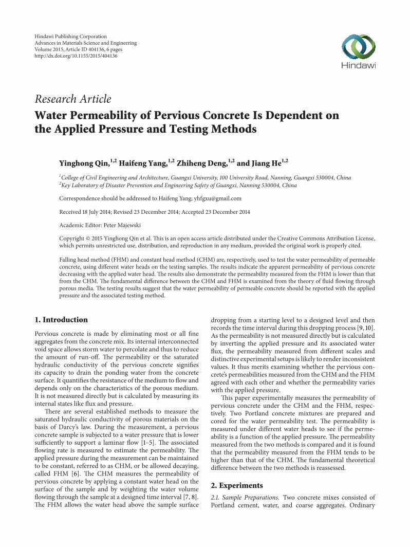
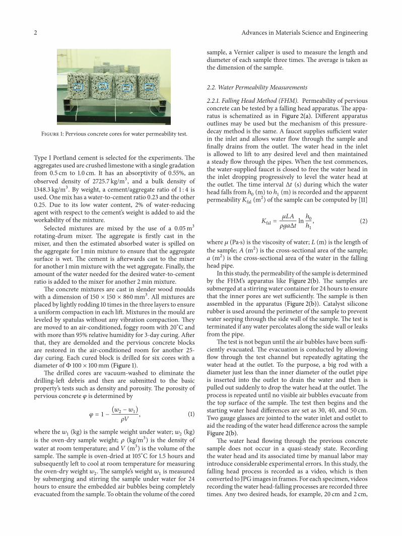
Figure 1: Pervious concrete cores for water permeability test.
Type I Portland cement is selected for the experiments. Theaggregates used are crushed limestone with a single gradationfrom 0.5 cm to 1.0 cm. It has an absorptivity of 0.55%, anobserved density of 2725.7 kg/m3, and a bulk density of1348.3 kg/m3. By weight, a cement/aggregate ratio of 1 : 4 isused. Onemix has a water-to-cement ratio 0.23 and the other0.25. Due to its low water content, 2% of water-reducingagent with respect to the cement’s weight is added to aid theworkability of the mixture.
Selected mixtures are mixed by the use of a 0.05m3rotating-drum mixer. The aggregate is firstly cast in themixer, and then the estimated absorbed water is spilled onthe aggregate for 1min mixture to ensure that the aggregatesurface is wet. The cement is afterwards cast to the mixerfor another 1min mixture with the wet aggregate. Finally, theamount of the water needed for the desired water-to-cementratio is added to the mixer for another 2min mixture.
The concrete mixtures are cast in slender wood mouldswith a dimension of 150 × 150 × 860mm3. All mixtures areplaced by lightly rodding 10 times in the three layers to ensurea uniform compaction in each lift. Mixtures in the mould areleveled by spatulas without any vibration compaction. Theyare moved to an air-conditioned, foggy room with 20∘C andwith more than 95% relative humidity for 3-day curing. Afterthat, they are demolded and the pervious concrete blocksare restored in the air-conditioned room for another 25-day curing. Each cured block is drilled for six cores with adiameter of Φ 100 × 100mm (Figure 1).
The drilled cores are vacuum-washed to eliminate thedrilling-left debris and then are submitted to the basicproperty’s tests such as density and porosity. The porosity ofpervious concrete 𝜑 is determined by
𝜑 = 1 −
(𝑤2− 𝑤1)
𝜌𝑉
, (1)
where the 𝑤1(kg) is the sample weight under water; 𝑤
2(kg)
is the oven-dry sample weight; 𝜌 (kg/m3) is the density ofwater at room temperature; and 𝑉 (m3) is the volume of thesample. The sample is oven-dried at 105∘C for 1.5 hours andsubsequently left to cool at room temperature for measuringthe oven-dry weight 𝑤
2. The sample’s weight 𝑤
1is measured
by submerging and stirring the sample under water for 24hours to ensure the embedded air bubbles being completelyevacuated from the sample. To obtain the volume of the cored
sample, a Vernier caliper is used to measure the length anddiameter of each sample three times. The average is taken asthe dimension of the sample.
2.2. Water Permeability Measurements
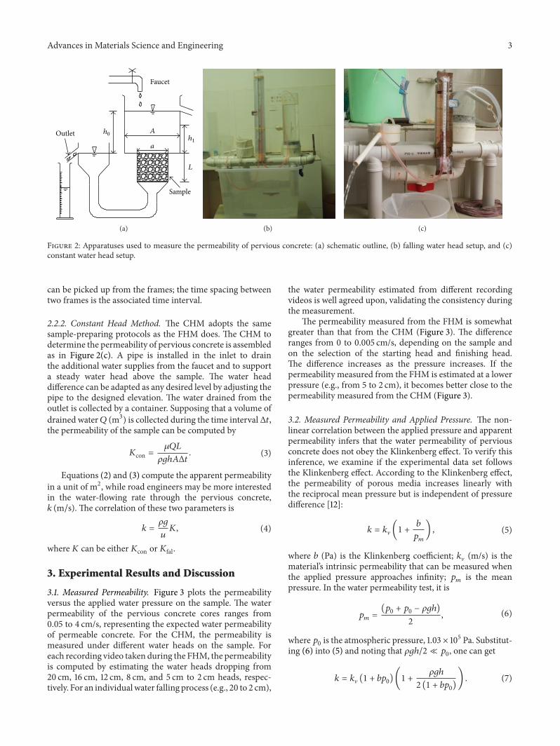
2.2.1. Falling Head Method (FHM). Permeability of perviousconcrete can be tested by a falling head apparatus. The appa-ratus is schematized as in Figure 2(a). Different apparatusoutlines may be used but the mechanism of this pressure-decay method is the same. A faucet supplies sufficient waterin the inlet and allows water flow through the sample andfinally drains from the outlet. The water head in the inletis allowed to lift to any desired level and then maintaineda steady flow through the pipes. When the test commences,the water-supplied faucet is closed to free the water head inthe inlet dropping progressively to level the water head atthe outlet. The time interval Δ𝑡 (s) during which the waterhead falls from ℎ
0(m) to ℎ
1(m) is recorded and the apparent
permeability𝐾fal (m2) of the sample can be computed by [11]
𝐾fal =𝜇𝐿𝐴
𝜌𝑔𝑎Δ𝑡
lnℎ0
ℎ1
, (2)
where 𝜇 (Pa⋅s) is the viscosity of water; 𝐿 (m) is the length ofthe sample; 𝐴 (m2) is the cross-sectional area of the sample;𝑎 (m2) is the cross-sectional area of the water in the fallinghead pipe.
In this study, the permeability of the sample is determinedby the FHM’s apparatus like Figure 2(b). The samples aresubmerged at a stirringwater container for 24 hours to ensurethat the inner pores are wet sufficiently. The sample is thenassembled in the apparatus (Figure 2(b)). Catalyst siliconerubber is used around the perimeter of the sample to preventwater seeping through the side wall of the sample. The test isterminated if any water percolates along the side wall or leaksfrom the pipe.
The test is not begun until the air bubbles have been suffi-ciently evacuated. The evacuation is conducted by allowingflow through the test channel but repeatedly agitating thewater head at the outlet. To the purpose, a big rod with adiameter just less than the inner diameter of the outlet pipeis inserted into the outlet to drain the water and then ispulled out suddenly to drop the water head at the outlet. Theprocess is repeated until no visible air bubbles evacuate fromthe top surface of the sample. The test then begins and thestarting water head differences are set as 30, 40, and 50 cm.Two gauge glasses are jointed to the water inlet and outlet toaid the reading of the water head difference across the sampleFigure 2(b).
The water head flowing through the previous concretesample does not occur in a quasi-steady state. Recordingthe water head and its associated time by manual labor mayintroduce considerable experimental errors. In this study, thefalling head process is recorded as a video, which is thenconverted to JPG images in frames. For each specimen, videosrecording the water head-falling processes are recorded threetimes. Any two desired heads, for example, 20 cm and 2 cm,
Advances in Materials Science and Engineering 3
L
A
Sample
Outlet
Faucet
a
h0h1
(a) (b) (c)
Figure 2: Apparatuses used to measure the permeability of pervious concrete: (a) schematic outline, (b) falling water head setup, and (c)constant water head setup.
can be picked up from the frames; the time spacing betweentwo frames is the associated time interval.
2.2.2. Constant Head Method. The CHM adopts the samesample-preparing protocols as the FHM does. The CHM todetermine the permeability of pervious concrete is assembledas in Figure 2(c). A pipe is installed in the inlet to drainthe additional water supplies from the faucet and to supporta steady water head above the sample. The water headdifference can be adapted as any desired level by adjusting thepipe to the designed elevation. The water drained from theoutlet is collected by a container. Supposing that a volume ofdrained water𝑄 (m3) is collected during the time intervalΔ𝑡,the permeability of the sample can be computed by
𝐾con =𝜇𝑄𝐿
𝜌𝑔ℎ𝐴Δ𝑡
. (3)
Equations (2) and (3) compute the apparent permeabilityin a unit of m2, while road engineers may be more interestedin the water-flowing rate through the pervious concrete,𝑘 (m/s). The correlation of these two parameters is
𝑘 =
𝜌𝑔
𝑢
𝐾, (4)
where𝐾 can be either𝐾con or𝐾fal.
3. Experimental Results and Discussion
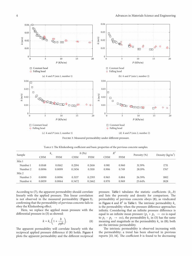
3.1. Measured Permeability. Figure 3 plots the permeabilityversus the applied water pressure on the sample. The waterpermeability of the pervious concrete cores ranges from0.05 to 4 cm/s, representing the expected water permeabilityof permeable concrete. For the CHM, the permeability ismeasured under different water heads on the sample. Foreach recording video taken during the FHM, the permeabilityis computed by estimating the water heads dropping from20 cm, 16 cm, 12 cm, 8 cm, and 5 cm to 2 cm heads, respec-tively. For an individualwater falling process (e.g., 20 to 2 cm),
the water permeability estimated from different recordingvideos is well agreed upon, validating the consistency duringthe measurement.
The permeability measured from the FHM is somewhatgreater than that from the CHM (Figure 3). The differenceranges from 0 to 0.005 cm/s, depending on the sample andon the selection of the starting head and finishing head.The difference increases as the pressure increases. If thepermeability measured from the FHM is estimated at a lowerpressure (e.g., from 5 to 2 cm), it becomes better close to thepermeability measured from the CHM (Figure 3).
3.2. Measured Permeability and Applied Pressure. The non-linear correlation between the applied pressure and apparentpermeability infers that the water permeability of perviousconcrete does not obey the Klinkenberg effect. To verify thisinference, we examine if the experimental data set followsthe Klinkenberg effect. According to the Klinkenberg effect,the permeability of porous media increases linearly withthe reciprocal mean pressure but is independent of pressuredifference [12]:
𝑘 = 𝑘V (1 +𝑏
𝑝𝑚
) , (5)
where 𝑏 (Pa) is the Klinkenberg coefficient; 𝑘V (m/s) is thematerial’s intrinsic permeability that can be measured whenthe applied pressure approaches infinity; 𝑝
𝑚is the mean
pressure. In the water permeability test, it is
𝑝𝑚=
(𝑝0+ 𝑝0− 𝜌𝑔ℎ)
2
, (6)
where 𝑝0is the atmospheric pressure, 1.03 × 10⁵ Pa. Substitut-
ing (6) into (5) and noting that 𝜌𝑔ℎ/2 ≪ 𝑝0, one can get
𝑘 = 𝑘V (1 + 𝑏𝑝0) (1 +𝜌𝑔ℎ
2 (1 + 𝑏𝑝0)
) . (7)
4 Advances in Materials Science and Engineering
0 5 10 15 200
0.01
0.02
0.03
0.04
Constant headFalling head
P (KPa/m)
k(m
/s)
(a) 𝑘 and 𝑃 (mix 1, number 1)
0 5 10 15 200
0.01
0.02
0.03
0.04
Constant headFalling head
P (KPa/m)
k(m
/s)
(b) 𝑘 and 𝑃 (mix 1, number 2)
0 5 10 15 200
0.01
0.02
0.03
0.04
Constant headFalling head
P (KPa/m)
k(m
/s)
(c) 𝑘 and 𝑃 (mix 2, number 1)
0 5 10 15 200
0.01
0.02
0.03
0.04
Constant headFalling head
P (KPa/m)
k(m
/s)
(d) 𝑘 and 𝑃 (mix 2, number 2)
Figure 3: Measured permeability under different pressure.
Table 1: The Klinkenberg coefficient and basic properties of the pervious concrete samples.
Sample 𝑘V 𝑏 (Pa) 𝑅2
Porosity (%) Density (kg/m3)CHM FHM CHM FHM CHM FHM
Mix 1Number 1 0.0148 0.0162 0.2194 0.2616 0.981 0.960 31.59% 1731Number 2 0.0096 0.0099 0.2456 0.3110 0.906 0.749 28.19% 1767
Mix 2Number 3 0.0090 0.0096 0.3137 0.2393 0.965 0.884 26.59% 1802Number 4 0.0059 0.0064 0.3472 0.2462 0.970 0.969 25.64% 1828
According to (7), the apparent permeability should correlatelinearly with the applied pressure. This linear correlationis not observed in the measured permeability (Figure 3),confirming that the permeability of pervious concrete fails toobey the Klinkenberg effect.
Here, we replace the applied mean pressure with thedifferential pressure in (5) as showed:
𝑘 = 𝑘V (1 +𝑏
𝜌𝑔ℎ
) . (8)
The apparent permeability will correlate linearly with thereciprocal applied pressure difference if (8) holds. Figure 4plots the apparent permeability and the different reciprocal
pressure. Table 1 tabulates the statistic coefficients (𝑘V, 𝑏)and lists the porosity and density for comparison. Thepermeability of pervious concrete obeys (8), as vindicatedin Figure 4 and 𝑅2 in Table 1. The intrinsic permeability 𝑘Vis the permeability when the pressure difference approachesinfinity. Considering that an infinite pressure difference isequal to an infinite mean pressure (𝑝
1+ 𝑝2→ ∞ is equal
to 𝑝1− 𝑝2→ ∞), the permeability 𝑘V in (5) has the same
meaning and magnitude as the permeability 𝑘V in (8); bothare the intrinsic permeability.
The intrinsic permeability is observed increasing withthe permeability; a trend has been observed in previousreports [13, 14]. The coefficient 𝑏 is found to be decreasing

Advances in Materials Science and Engineering 5
Constant headFalling head
0 2 4 60
0.01
0.02
0.03
0.04k
(m/s
)
P−1 (/KPa)
(a) 𝑘 and 1/𝑃 (mix 1, number 1)
Constant headFalling head
0 2 4 60
0.01
0.02
0.03
0.04
k(m
/s)
P−1 (/KPa)
(b) 𝑘 and 1/𝑃 (mix 1, number 2)
Constant headFalling head
0 2 4 60
0.01
0.02
0.03
0.04
k(m
/s)
P−1 (/KPa)
(c) 𝑘 and 1/𝑃 (mix 2, number 1)
Constant headFalling head
0 2 4 60
0.01
0.02
0.03
0.04
k(m
/s)
P−1 (/KPa)
(d) 𝑘 and 1/𝑃 (mix 2, number 1)
Figure 4: Klinkenberg Effect of the measured permeability of pervious concrete.
with the increase of the density and porosity, suggestingless dependence of the apparent permeability at high porousconcrete.
3.3. Difference betweenConstantHead and FallingHeadMeth-ods. As the apparent permeability estimated from the CHMand the FHM exhibits differences, it merits examining themechanism behind. From both methods, the water flowingrate through the sample V (m/s) is computed according toDarcy’s law:
V = −𝐾
𝜇
∇𝑃, (9)
where ∇𝑃 is the pressure gradient across the sample (Pa/m).According to the Bernoulli equation, the water gradientapplied across the sample is proportional to the water headdifference ℎ; that is,
∇𝑃 =
𝜌𝑔ℎ
𝐿
. (10)
For the CHM, the flowing rate through the sample canbe estimated from the water collected by the container and iscomputed by
V =𝑄
𝐴Δ𝑡
. (11)
Substituting (10)-(11) into (9), one has (3). It means the CHMestimates the permeability of pervious concrete by assuminga laminar flow.
For the FHM, the water flow through the sample obeysthe mass conservation law and follows
V × 𝐴 =
𝑑ℎ
𝑑𝑡
× 𝑎. (12)
Substituting (10) and (12) into (9), one has
𝑑ℎ
ℎ
= −
𝜌𝑔𝐾𝐴
𝜇𝐿𝑎
𝑑𝑡. (13)
6 Advances in Materials Science and Engineering
If the permeability 𝐾 is independent of the applied pressure(ℎ), (13) can be integrated directly and the integral is thesame as (2). This means that, in addition to the assumptionof a laminar flow, the FHM also assumes that the apparentpermeability is independent of the applied pressure.
In (2), any two water heads at any associated interval canbe selected to estimate the permeability of previous concreteunder the FHM test. This selection would not influence themeasured permeability if the permeability𝐾 is constant.
However, the selection does influence the estimatedwaterpermeability, as substantiated in Figures 3 and 4. The waterpermeability of permeable concrete tends to decrease withthe increase of the pressure. The correlation obeys (8).Substituting (8) into (13), one can integrate (13) and solve forthe permeability, as expressed in
𝐾fal =𝜇𝐿𝑎
𝜌𝑔𝐴Δ𝑡
ln(ℎ0+ 𝑏/𝜌𝑔
ℎ + 𝑏/𝜌𝑔
) . (14)
Equation (14) is equal to (1) only if 𝑏 vanishes. In the caseof 𝑏 = 0, the slope of the linear line in Figure 4 is zeroor the apparent permeability is independent of the imposedpressure difference. As natural logarithm is a monotonicallyincreasing function, neglecting the term of 𝑏/𝜌𝑔 overesti-mates the right-hand side of (14) and thus overestimates thewater permeability. That is why the estimated permeabilityfrom the FHM tends to be higher than that from the CHM(Figure 3).
Therefore, the FHM presumes the apparent permeabilityis independent of the applied pressure difference but theCHM does not. This assumption introduces difference to thepermeability measured from the two methods.
4. Conclusions
Falling head and constant head methods are, respectively,used to measure the permeability of pervious concrete sam-ples. The measured permeability is found to be decreasingwith the applied pressure difference on the sample but doesnot obey the Klinkenberg effect. The permeability is foundto be increasing linearly with the reciprocal water pressure,similar to the Klinkenberg effect.
The permeability measured by the CHM is lower thanthat by the FHM. The selection of the starting and finishingwater heads from the FHM strongly affects the calculatedpermeability. The difference decreases as the water headapproaches zero.Due to this correlation, thewater permeabil-ity of permeable concrete should be reported with the appliedpressure and the associated testing method.
Conflict of Interests
The authors declare that there is no conflict of interestsregarding the publication of this paper.
Acknowledgments
This work is supported by National Natural Science Founda-tion of China (Grant nos. 51268005 and 51308135) and by the
Scientific Research Foundation of Guangxi University (Grantno. XGZ130237). The authors are indebted to their graduatestudents Yingpu Xie, Ting Bao, and Yumei Wang for the labworks.
References
[1] ASTM International, “Standard test method for permeabilityof Granular soils (constant head),” ASTM D2434-68, ASTMInternational, West Conshohocken, Pa, USA, 2000.
[2] ASTM International, ASTM-D5048-03, Standard Test Methodfor Measurement of Hydraulic Conductivity of Saturated PorousMaterials Using a Flexible Wall Permeameter D4084-03, ASTMInternational, West Conshohocken, Pa, USA, 2003.
[3] S. B. Park, B. Lee, J. Lee, and Y. I. Jang, “A study on the seawaterpurification characteristics of water-permeable concrete usingrecycled aggregate,” Resources, Conservation and Recycling, vol.54, no. 10, pp. 658–665, 2010.
[4] T.Tho-In, V. Sata, P. Chindaprasirt, and C. Jaturapitakkul, “Per-vious high-calcium fly ash geopolymer concrete,” Constructionand Building Materials, vol. 30, pp. 366–371, 2012.
[5] Y. Qin, H. Yang, Z. Deng, and J. Zhang, “A simplified model forcomputing pollutants release from granular pavement base tolocal aquifer,” Environmental Earth Sciences, vol. 75, no. 5, pp.1533–1540, 2014.
[6] R. Zaharieva, F. Buyle-Bodin, F. Skoczylas, and E. Wirquin,“Assessment of the surface permeation properties of recycledaggregate concrete,” Cement and Concrete Composites, vol. 25,no. 2, pp. 223–232, 2003.
[7] J. P. Coughlin, C. D. Campbell, and D. C. Mays, “Infiltrationand clogging by sand and clay in a pervious concrete pavementsystem,” Journal of Hydrologic Engineering, vol. 17, no. 1, pp. 68–73, 2011.
[8] M. Sonebi and M. T. Bassuoni, “Investigating the effect ofmixture design parameters on pervious concrete by statisticalmodelling,” Construction and Building Materials, vol. 38, pp.147–154, 2013.
[9] O. Deo, M. Sumanasooriya, and N. Neithalath, “Permeabilityreduction in pervious concretes due to clogging: experimentsandmodeling,” Journal of Materials in Civil Engineering, vol. 22,no. 7, pp. 741–751, 2010.
[10] C. Lian and Y. Zhuge, “Optimum mix design of enhanced per-meable concrete—an experimental investigation,” Constructionand Building Materials, vol. 24, no. 12, pp. 2664–2671, 2010.
[11] F. Montes, S. Vlavala, and L. M. Haselbach, “A new test methodfor porosity measurements of portland cement pervious con-crete,” Journal of ASTM International, vol. 2, no. 1, pp. 1–13, 2005.
[12] L. J. Klinkenberg, “The permeability of porous media to liquidand gases,” in Drilling and Production Practice, AmericanPetroleum Institute, New York, NY, USA, 1941.
[13] J. Kevern, K. Wang, M. T. Suleiman, and V. R. Schaefer, MixDesign Development for Pervious Concrete in Cold WeatherClimates, Iowa State University, Ames, Iowa, USA, 2005.
[14] F. Montes and L. Haselbach, “Measuring hydraulic conductivityin pervious concrete,” Environmental Engineering Science, vol.23, no. 6, pp. 960–969, 2006.

Submit your manuscripts athttp://www.hindawi.com
ScientificaHindawi Publishing Corporationhttp://www.hindawi.com Volume 2014
CorrosionInternational Journal of
Hindawi Publishing Corporationhttp://www.hindawi.com Volume 2014
Polymer ScienceInternational Journal of
Hindawi Publishing Corporationhttp://www.hindawi.com Volume 2014
Hindawi Publishing Corporationhttp://www.hindawi.com Volume 2014
CeramicsJournal of
Hindawi Publishing Corporationhttp://www.hindawi.com Volume 2014
CompositesJournal of
NanoparticlesJournal of
Hindawi Publishing Corporationhttp://www.hindawi.com Volume 2014
Hindawi Publishing Corporationhttp://www.hindawi.com Volume 2014
International Journal of
Biomaterials
Hindawi Publishing Corporationhttp://www.hindawi.com Volume 2014
NanoscienceJournal of
TextilesHindawi Publishing Corporation http://www.hindawi.com Volume 2014
Journal of
NanotechnologyHindawi Publishing Corporationhttp://www.hindawi.com Volume 2014
Journal of
CrystallographyJournal of
Hindawi Publishing Corporationhttp://www.hindawi.com Volume 2014
The Scientific World JournalHindawi Publishing Corporation http://www.hindawi.com Volume 2014
Hindawi Publishing Corporationhttp://www.hindawi.com Volume 2014
CoatingsJournal of
Advances in
Materials Science and EngineeringHindawi Publishing Corporationhttp://www.hindawi.com Volume 2014
Smart Materials Research
Hindawi Publishing Corporationhttp://www.hindawi.com Volume 2014
Hindawi Publishing Corporationhttp://www.hindawi.com Volume 2014
MetallurgyJournal of
Hindawi Publishing Corporationhttp://www.hindawi.com Volume 2014
BioMed Research International
MaterialsJournal of
Hindawi Publishing Corporationhttp://www.hindawi.com Volume 2014
Nano
materials
Hindawi Publishing Corporationhttp://www.hindawi.com Volume 2014
Journal ofNanomaterials


![Strength Development and Water Permeability of Engineered ......[9] L.M. Haselbach, S. Valavala and F. Montes, Permeability predictions for sand-clogged Portland cement pervious concrete](https://img.dokumen.tips/doc/110x75/60f84414cca4135aa749a732/strength-development-and-water-permeability-of-engineered-9-lm-haselbach.jpg)