Embed Size (px)
Citation preview

REPORT
OF
AERB COMMITTEE TO REVIEW
SAFETY OF INDIAN NUCLEAR POWER PLANTS
AGAINST EXTERNAL EVENTS OF NATURAL ORIGIN
August 2011


CONTENTS
1. Background 1
2. Committee’s work approach 2
3. Observations 4
4. Conclusions and recommendations 7
Annexures
1. O.M. constituting the committee 17
2. Brief description of the Fukushima Accident 19
3. AERB regulations on NPP safety against external events 27
4. Committee’s work plan 36
5. Summarized Interim reports of Working Groups 39
6. Review findings 82
7. Recommendations for extreme natural events other than
earthquake and tsunami
106
8. Safety assessment of KKNPP in the wake of Fukushima
accident
108
9. List of abbreviations 111


1
August 31, 2011
REPORT OF AERB COMMITTEE TO REVIEW SAFETY OF
INDIAN NUCLEAR POWER PLANTS AGAINST EXTERNAL
EVENTS OF NATURAL ORIGIN
1. Background
The Great East Japan Earthquake of magnitude 9 that occurred on March 11,
2011 generated a series of large tsunami waves that struck the Fukushima
Dai-ichi and Fukushima Dai-ni nuclear power plants (NPPs) on the east coast
of Japan. As per reports from the Japanese authorities, magnitudes of both the
earthquake and the tsunami were beyond the design basis for these NPPs. The
flooding of the site due to tsunami waves incapacitated the power supplies
which led to a nuclear accident encompassing units 1, 2 and 3 of Fukushima
Dai-ichi NPP. Cumulative impact of the accident was unprecedented in terms
of damage to the reactor cores in units 1, 2, and 3 (core of unit-4 had been
unloaded at that time into the spent fuel pool) and impairment of cooling to
the irradiated fuel in the spent fuel storage pools of all the four units. Four
hydrogen explosions also occurred that caused damage in the reactor
buildings of units 1, 3 and 4 and the wet well of unit-2. The accident resulted
in significant release of radioactivity into the public domain, including to the
sea, and emergency measures like evacuation of people in the vicinity of the
NPP and some restrictions on consumption of food items etc. had to be
implemented. It took a large effort over several days before units-1, 2 and 3
could be stabilized and cooling of fuel in the storage pools could be restored.
The accident was rated at level-7, the highest level of the International
Nuclear and Radiological Event Scale. There was no significant adverse
2
impact on the safety of units 5 and 6 of the Dai-ichi NPP and the 4 units of
Dai-ni NPP as well as on the Onagawa NPP (3 units) and the Tokai NPP (1
unit) located nearby.
Chairman, AERB constituted a committee on March19, 2011 to review the
safety of Indian NPPs against external events of natural origin, in the light of
the Fukushima accident (annexure-1).
2. Committee’s work approach
Work plan
After review of the various reports on the Fukushima accident it was realized
that from the information available presently it is not possible to draw any
firm conclusions on the causes of the accident in terms of design
shortcomings and/or inadequacies in procedures or in their implementation (a
brief description of the Fukushima accident is given in annexure-2).
However it was apparent that the accident was mainly caused by
• Severe flooding caused by the beyond design basis tsunami, and
• Consequent prolonged station black out (SBO) i.e. loss of off-site as
well as on-site AC power supplies at the NPP.
Accordingly, the committee drew up its work plan focusing on these two
major areas viz. Beyond Design Basis Events (BDBE) of natural origin and
prolonged SBO. The current regulations of AERB on the safety of NPPs
against natural events (annexure-3) were kept in view while drawing up the
work plan. The committee’s work plan is given in annexure- 4.
Work methodology
The committee constituted expert working groups to

3
a) Develop the guidelines for deciding on the magnitude and related
issues concerning beyond design basis external events of natural
origin,
b) Review all relevant aspects related to external events of natural
origin and prolonged SBO for the boiling water reactors of TAPS-
1&2
c) Examine all relevant aspects related to external events of natural
origin and SBO for the Pressurized Heavy Water Reactor (PHWR)
based NPPs. In this context Working Groups were constituted to
conduct reviews in the following areas:
1. Station blackout & ultimate heat sink
2. Electrical systems
3. Control & instrumentation
4. Spent fuel storage facilities.
5. Heavy water upgrading plants
d) Examine the safety issues related to radioactive waste disposal
facilities at the NPPs under extreme natural events, and
e) Examine the severe accident management guidelines for NPPs.
Summarized interim reports of the working groups are given in annexure-5.
Reports of the working groups were discussed in detail in eight meetings of
the committee to arrive at the review findings (annexure-6) and the
committee’s conclusions & recommendations. Information contained in the
report of the IAEA Fact Finding Mission that visited the Fukushima NPP
during May 2011 was also kept in view while arriving at the conclusions and
recommendations.

4
3. Observations
3.1 Use of operating experience feedback for enhancing safety of NPPs has
all along been accorded high importance in India. Lessons learned from
Three Mile Island and Chernobyl accidents and from several other
operational incidents in NPPs in India and abroad, as also from new
knowledge gained through research have been appropriately used for
design and procedural improvements to enhance safety of our NPPs. The
present exercise of reviewing the safety of our NPPs in the light of the
Fukushima accident is to be viewed in this context.
3.2 As per AERB regulations, all key operating personnel as also station
management personnel in Indian NPPs are graduate engineers who are
formally authorized to carry out their respective duties only after
successful completion of intense training. In addition, operating
personnel have to periodically renew their licenses after clearing
simulator training, written examination and interview by an expert
committee. In some other NPP operating countries there is no
requirement of engineering degree as educational qualification for
reactor operators. Thus the NPP operators in India are better placed to
handle off-normal situations in the plant compared to their counterparts
in several other countries.
3.3 All NPPs in India undergo Periodic Safety Reviews (PSR) following the
procedure prescribed in AERB regulations. The PSRs comprise of a
detailed design and operational safety review that is conducted every 10
years and a brief but comprehensive review which is done every 5 years.
For older NPPs special safety reviews have been carried out when they
were approaching the end of their originally proclaimed design life,
which is based on the plant’s estimated economic life or, in some cases,
5
on technical considerations as understood at the time of their design.
These reviews are done based on current safety standards.
3.4 A large number of safety upgrades have been implemented over the years
in our NPPs, especially in the old units, based on the outcome of the
various safety reviews mentioned above. Some upgrades have been
made on the basis of seismic reevaluation of the structures, systems and
components (SSCs) of the NPPs and the outcome of studies on potential
flooding due to postulated failure of dams upstream of the water
reservoirs at the NPP sites. The committee noted that these safety
upgrades have substantially enhanced the safety of our NPPs including
their capability to withstand natural events.
3.5 The magnitude of postulated design basis natural events and the related
requirements for siting and design of NPPs, as specified in AERB safety
regulations, are found to be appropriate and sufficiently conservative.
However in the light of Fukushima experience it is considered prudent to
further enhance this conservatism and also postulate the magnitude of
beyond design basis natural events.
3.6 The submarine faults capable of generating tsunamis are located at very
large distances of more than 800km from the Indian coast. Thus, unlike
in the Fukushima case, the possibility of simultaneous occurrence of an
earthquake and a tsunami at our NPPs, is almost non-existent.
3.7 A major lesson learned from the Fukushima experience is that capability
to cool irradiated fuel in the reactor core and in the spent fuel storage
facilities must remain available in the event of prolonged SBO as also in
the face of beyond design basis natural events.
3.8 PHWRs form the back bone of the current Indian nuclear power
programme. In this design, cooling of the reactor core, with the plant in

6
hot shut down state, is achieved by natural convection flow of reactor
coolant through steam generators. With the design provision for
charging water to the secondary side of the steam generators using diesel
engine driven pumps, this mode of core cooling can be maintained even
under extended SBO. The efficacy of this design feature got amply
demonstrated during the 17 hours long SBO caused by the turbine hall
fire incident at Narora unit-1 in 1993 when reactor core cooling could be
successfully maintained.
3.9 In the case of TAPS-1&2, which is a boiling water reactor (BWR) based
NPP, core cooling under SBO can be maintained up to about 8 hours by
natural convection circulation of reactor coolant through the emergency
condenser. Heat from the coolant is removed by boiling of water present
on the secondary side of the emergency condenser. The inventory of
water on the secondary side of the emergency condenser is sufficient for
cooling the core for about 8 hours only and thereafter it must be made
up.
3.10 The heat load from irradiated fuel stored to design capacity in the spent
fuel storage pools is much less and the inventory of water in the pools
much larger at our NPPs in comparison to the corresponding heat load
and water inventory in the spent fuel storage pools at Fukushima NPP.
Consequently, for the Indian NPPs, submergence of the fuel in the pool
water is assured for a time period of at least one week under SBO, even
with the most conservative assumptions on the quantum of decay heat
from the stored fuel and without any credit for operator action.

7
4. Conclusions and recommendations
External events
4.1 Though AERB regulations with respect to design basis for external
events are sufficiently conservative, it is recommended that treatment of
uncertainties in data and certain computational procedures should be
improved to obtain an even higher degree of conservatism in the
assessment of the magnitude of design basis external events of natural
origin. The revised guidelines so generated may be considered for
inclusion in AERB regulations.
4.2 Regulatory requirements on derivation of seismic design basis ground
motion (DBGM) should address the limitations of current methodologies
because of lack of sufficient and relevant earthquake data and other
uncertainties concerning site tectonics. The AERB guide on seismic
studies and DBGM may be revised accordingly.
4.3 It is observed that seismic signal based automatic reactor trip is presently
provided in NAPS and KAPS only. In other operating units, seismic
alarms are provided and in the event of an earthquake the reactor has to
be tripped manually. Seismic signal based automatic reactor trip should
be implemented in all reactor units. Also, seismic switches and sensors
that are located outside the reactor buildings should be protected against
any flooding at the site.
4.4 The Fukushima accident has shown that occasionally the magnitude of
natural events can be higher than what is considered in design. It is
therefore prudent to make additional design provisions such that at least
the basic safety functions for the NPPs are not impaired even under
beyond design basis natural events (or extreme events). Towards this
aim it is recommended that the parameters for each postulated extreme

8
natural event be defined conservatively using the best available
analytical methods. While design basis external events should govern
the design of SSCs, functionality of the most safety relevant SSCs
should still be maintained under extreme events.
4.5 In spite of the conservative estimates of the design basis external events
of natural origin, there is a residual risk of exceeding these estimates.
While absolute quantification of beyond design basis events is not
feasible, their probable magnitudes should still be defined for safety
margin assessment. The expert group on external events, after detailed
deliberations on the physical bounds of the underlying parameters as
currently understood, and the inherent uncertainties, has recommended
interim measures for evaluating extreme natural events other than
earthquake and tsunami. These recommendations are provided in
annexure-7. For assessment of extreme tsunami event it is recommended
that all physically possible combinations and variations of tsunamigenic
source parameters and accurate near shore data should be considered.
The group is working on developing methodology to define extreme
earthquake event at a level higher than SSE. This work should be
completed at the earliest possible.
4.6 Assessing the magnitude of extreme natural events is a highly
challenging task due to the inherent uncertainties involved, especially in
respect of tsunami wave heights. In this context the committee noted that
a detailed exercise is in progress at AERB, using a computer code for
analysis that is validated using the data from the 2004 Indian Ocean
tsunami, for estimating the maximum tsunami wave heights that can
possibly be generated from the sub-sea faults around the Indian coasts.
This work should be completed expeditiously.

9
The work done so far indicates that the maximum postulated flood level
at Kalpakkam coast is likely to get revised upwards and consequently
the corresponding design improvements for MAPS will have to be
considered. The flood level assessment is based on a tsunami generated
from a sub-sea earthquake caused by the Andaman-Nicobar-Sumatra
fault and takes into account, in a most conservative manner, the fault
parameters and the directivity of tsunami propagation towards the
Kalpakkam coast. The Prototype Fast Breeder Reactor at this site is
likely to remain unaffected due to this revision as its grade level is
sufficiently high. For all other coastal NPP locations there will be no
change in the maximum postulated flood level.
4.7 Design provisions should be made to ensure safety even for the
conservatively estimated magnitude of extreme events without any
unreasonable demand on operator actions. For example, provision of air
cooled diesel generators (DGs) capable of remaining operational even
under extreme events, and, portable power packs that could be easily
hooked up at pre-identified points, to supply back up power for
performing essential safety functions and obtaining information on
important safety parameters, could be considered as a further measure of
defense in depth.
4.8 A beyond design basis external event may disable the facilities available
at the NPP site for monitoring and control of important reactor
parameters. It may also result in physical isolation of the site such that it
may not be possible to receive outside help for a considerable period of
time. Creation of an emergency facility at each NPP site which will
remain functional under such conditions is therefore recommended. The
facility should have adequate radiation shielding and should be
seismically qualified. It should also have provisions for communication
10
with relevant agencies and for obtaining information from all units at the
site to help decide on further course of actions, as also for food, resting
etc. for essential personnel for a period of about one week.
PHWRs
4.9 As already stated, the PHWR based NPPs, which account for 18 of the
20 operational NPP units in India presently, have a distinct advantage in
respect of core cooling capability under SBO. This is because core
cooling in these reactors can be sustained under SBO condition by
natural convection flow of the reactor coolant through steam generators
(SGs). Heat from the SGs is removed by boiling of water on their
secondary side and the steam so produced is discharged to the
atmosphere. Design provisions exist for charging water to the SGs by
diesel engine driven pumps, without any need for electric power, and the
water inventory available for this purpose, without any replenishment, is
sufficient for more than one week’s requirement.
4.10 To ensure natural convection flow of the reactor coolant through SGs,
any significant voiding in the reactor coolant system should be
prevented, which may appear in the system if losses due to leakages
from the system are not made up. It is therefore recommended that a
reliable back-up provision should be made for PHT make-up during
extended SBO.
4.11 Presently the safety analysis has been done for SBO duration of 24
hours. This should be extended to the period beyond 24 hours.
Temperature rise of moderator and vault water during SBO beyond 24
hours should also be assessed and means to limit these temperatures
should be provided.

11
4.12 Assured operability of the fire water system during extended SBO is
extremely important. Towards this, instituting periodic maintenance and
surveillance programme on fire water system piping is recommended. The
fire water pumps should be qualified for sustained operation by endurance
testing. The starter batteries and their chargers for these pumps should be
relocated at a higher elevation to protect them against flooding. Logistics for
manual pumping of fuel to diesel operated fire water pumps in case of non-
availability of the normal pumps need to be confirmed. Similarly the vent
lines of the underground diesel storage tanks should also be suitably raised
to prevent any water ingress into the tanks during flooding of the NPP sites.
TAPS -1&2
4.13 In the case of the boiling water reactors of TAPS-1&2, core cooling under
SBO can be maintained for about 8 hours by natural convection cooling of
reactor coolant by the water present on secondary side of the emergency
condenser. To ensure reactor cooling in this mode beyond 8 hours, back up
provisions should be made for replenishing loss of inventory by injection of
water to the reactor coolant system as well as to the secondary side of the
emergency condenser.
There is also a need to enhance compressed air back up to the relief valves in
the auto blow down system (ABDS), to ensure their operability to
depressurize the reactor during extended SBO. Presently operation of these
valves during SBO is possible for a limited number of operations, till their
local compressed air accumulators drain out.
4.14 Some of the safety systems including class III power supply system in
TAPS-1&2 are located below the revised reference flood level for the site
and therefore external flooding at TAPS has the potential to cause SBO. The

12
equipments for emergency core cooling and filtered containment venting are
also located below the revised reference flood level.
A detailed study is hence necessary to identify the design improvements
required to ensure availability of the above systems during external flooding
and the requisite corrective actions should be implemented at the earliest.
Interim arrangements such as alternate means to inject water into the
secondary side of the emergency condenser and to the reactor coolant system
should be considered if the permanent solutions are likely to take
considerable time for implementation (NPCIL has recently informed that
these interim arrangements have already been made).
4.15 There are also certain issues with regard to spent fuel pool integrity and pool
make up capability for TAPS-1&2 consequent to a beyond design basis
seismic event, such as integrity of fuel pool gates, loss of pool water due to
sloshing and operability of service/demineralised water pumps for pool
water make up. These pumps are also located below the revised reference
flood level. All these issues should be examined in detail and appropriate
modifications carried out to enhance safety margins and availability of
essential equipment under such severe external events.
KKNPP
4.16 The KKNPP units-1&2 are now in advanced stages of construction with
initial commissioning activities for unit-1 already initiated. The safety
review of KKNPP, in the light of Fukushima accident, is being done by the
AERB’s Advisory committee on project safety review of light water reactors
(ACPSR-LWR). However for the sake of completeness, a short note on the
subject is attached (annexure-8).
It can be seen that KKNPP design already has several advanced safety
features including those for ensuring safety against external events of

13
natural origin and for management of design basis as well as beyond
design basis accidents. However as a matter of abundant caution a
review is being done in the wake of the Fukushima accident to identify
further improvements if any that need to be made.
Spent fuel storage facilities
4.17 For the spent fuel storage pools at our NPPs it is seen that the stored fuel
remains submerged in water for a period ranging from 9 to 16 days in
the older plants viz. TAPS-1&2, RAPS-1&2 and MAPS-1&2, and for
over one month in other plants, without any cooling or addition of water.
Nevertheless an external water hookup provision for charging water in
the pools for all the operating plants should be implemented. This make
up capability should remain unaffected by the external events and SBO.
Provision for monitoring the level and temperature of pool water and
radiation fields inside the spent fuel storage buildings under SBO should
also be made.
4.18 Detailed site specific safety assessment of spent fuel storage bays should
be carried out with respect to structural integrity and leak-tightness of
pools, loss of pool water from sloshing and, stability of fuel racks and
mechanical handling equipment in case of extreme earthquake event.
Severe accidents
4.19 In spite of all the safety features provided, the extremely remote
possibility of an accident leading to partial or total melting of fuel in the
reactor core due to unforeseen reasons should still be deterministically
taken into consideration. Provisions for management of such an
accident, termed as severe accident, need to be made such that the
operators are able to control its progression and mitigate its

14
consequences in terms of preventing, or at least minimizing, any
significant adverse impact in the public domain.
4.20 In the area of severe accident management significant progress has been
made in our country in the recent past in terms of analysis and R&D
work. Broad guidelines for management of severe accidents in PHWRs
including the management of hydrogen generated from the reaction
between overheated fuel & its cladding and the reactor coolant have also
been worked out. It is seen that in case of PHWRs severe accident
management in terms of arresting the progression of the accident is
comparatively simpler. This is on account of the presence of the large
quantity of moderator heavy water at low pressure and temperature
inside the reactor vessel and the large inventory of water in the vault that
surrounds the vessel, both capable of acting as a heat sink to absorb
decay heat from the fuel. Therefore the strategy for severe accident
management essentially comprises of maintaining sufficient inventory
and adequate cooling of moderator and vault water.
The analysis and R&D referred above for severe accident management
should be expeditiously translated into design provisions together with
related procedures for the operating as well as under construction
PHWRs.
4.21 In the case of TAPS-1&2, preparatory work for inerting the primary
containment, for management of any hydrogen escaping from the reactor
pressure vessel in case of a severe accident, has been taken up.
Similarly, work on development of severe accident management
guidelines has also been initiated. These tasks should be completed on
priority.
Other recommendations

15
4.22 In case of damage to the off-site power supply lines and to the station
switchyard during an external event, it is important that these be repaired
and brought back into service at the earliest. Necessary preparedness for
this purpose including stocking requisite spares and logistics of
obtaining services of expert agencies should be looked into.
4.23 Functioning/operability of all safety related control and instrumentation
(C&I) including their backup instrument air accumulators, and integrity
of their supports/panels, should be checked for beyond design basis
earthquake level, after the relevant parameters for such an event are
available.
4.24 The practice of storing spent radioactive ion exchange resins in
underground tanks should be discontinued as in case of earthquake or
severe flooding this can cause spread of radioactive contamination. The
resins presently stored in such tanks at TAPS and MAPS should be
appropriately treated and disposed off.
4.25 Functional integrity of radioactive liquid effluent storage tanks and
surrounding dykes at NPPs should be assessed under beyond design
basis external events and corrective measures implemented as necessary
4.26 Capabilities need to be developed to treat large quantities of liquid waste
that may get generated in case of an accident. Large capacity
transportable radioactive effluent treatment modules, which can be
speedily deployed at any NPP site, could be one possibility.
4.27 Site specific assessment of existing structures and equipment,
specifically the tall structural steel towers and distillation columns of the
heavy water upgrading plants, should be carried out for postulated level
of external events, especially earthquakes, and any impact of their failure
on nearby plant facilities should be checked.

4.28In addition to the recommendations listed above, various other
suggestions have also been made in the detailed reports of the working
groups. Actions on those suggestions should also be taken as
appropriate. In this regard, the committee noted that even while its
deliberations were in progress, NPCIL has proactively initiated work
towards implementation of the recommendations of the committee and
those from its own review and has drawn up an action plan for this work.
It is also seen that pending implementation of permanent design
improvements which require procurement of materials, components etc.
and working out detailed engineering, some interim alrangements for
meeting the intent of the recommendations have already been made.
I.D. Gupta) (Prof. C.V .Murfy)
(On behalf of Dr. B.N. Goswami)
@(A.G. Chhatre) (L.R.Bishnoi)
(DfS.Krishnan)
(S.A.Bhardwaj) (Dr. A.K. Ghosh)
(S.K. Sharma)
16

Safety Regulation1983 - 2m8
3{rzIHCHAIRMAN
No.GH/AERBl2st2111t +
dfcfr{
nr*H6r{GOVERNMENT OF INDIA
Annc- utE-!*A*#*itEnergyRegulatoryBoard
March 19,2011
Sub: Committee to review the safety of Indian Nuclear Power Plantsin the light of earthquake and tsunami in Japan
The severe earthquake of March 11, 201 1 in Japan foll ed by high intensity tsunami
has resulted in damage in a number of reactors at Fukushima Nuclear P r Station, A
committee eonsisting of the following is hereby constituted to review the safety of lndian Nuclear
Power Plants in the light of the above incident.
1. Shri S.K. Sharma, Former Chairman, AERB - Chairman
2. Shri$.K. Chande, Vice Chairman, AERB - Member
3. Shri$.A. Bhardwaj, Director(Tech.), NPCIL - Member
4. Dr. A.K. Ghosh, Director, HS&E Group, BARC - Member
5. Prof. C.V.R. Murthy, llT, Madras - Member
6. Dr, l.D. Gupta, Director, CentralWater & Power Research Station, Pune - Member
7, Dr. B.N. Goswami, Director, Indian lnstt. of TropicalMeteorology, Pune - Member
8. Shri R, Chowdhury, Former Director, RG, BARC - Member
9. $hriA.G. Chhatre, Associate Director (SA&S), NPCIL - Member
10. Shri L.R. Bishnoi, Head, S&SED, AERB - Member-Secretary
The Committee may review
(1) Capability of Indian Nuclear Power Plants to withstand earthquakes and other
extemal events such as tsunamis, cyclones, floods, etc.
WdISO 9001:2008Organisation
f+qTq-6'qr{, srsJstRrflK, ir$. +oo osaNIYAMAK BHAVAN, ANUSHAKTINAGAR, MUMSAI . +OO 094
Er'fi /TELEPHONE : 9l-22-2566 2943, 2599 0604$w/ FAX : s1-22-z5s6 2s44, assE s717, zss8 g2go
E-mail: chairman @ a€tb.gov.in+{qtFc/ WEBSTTE : www.aerb.gov.in
L7

r+{q|g 6€il? fuFrs' qfrrqATOH|C ETIERGY REGUU{TORY BOARO
-2-
CMD, N I]-, Di r, BARC
Vie Chsirman, RB
,AERB C
T g

19
Annexure-2
BRIEF DESCRIPTION OF THE FUKUSHIMA ACCIDENT
Background
The pacific coast of east Japan was struck by an off shore earthquake of
magnitude (Mw) 9.0, the largest in Japan’s recorded history, at 14:46 (JST) on
March11, 2011. The earthquake generated large tsunami waves that struck the
Tohoku district in a series of waves, the highest being 38.9m at Aneyoshi,
Miyako. The earthquake and the tsunami caused widespread destruction of
life and property. As well as other enterprises, four nuclear power plant
(NPP) sites on the northeast coast of Japan were affected to varying degrees
by the earthquake and the tsunami. These sites (shown below with distances
from the earthquake epicenter and recorded maximum ground accelerations)
were Higashi Dori (one unit), Onagawa (three units), Fukishima Dai-ichi (six
units) & Dai-ni (four units) and Tokai II (one unit).

20
Of these fifteen units, eleven that were operating at the time of the earthquake
were shutdown automatically on sensing the earthquake. Four units (one unit
of Higashi Dori and units 4, 5 and 6 of Fukushima Dai-ichi) were already in
shutdown state. The large tsunami waves that followed affected all the NPPs
to varying degrees, with most serious consequence occurring at Fukushima
Dai-ichi. Further description in this write up pertains to Fukushima Dai-ichi
NPPs only.
The Fukushima Dai-ichi Nuclear Power Plant
The Fukushima Dai-ichi NPP site has six Boiling Water Reactor (BWR)
units. Unit-1 is 460 MWe BWR-3 with mark-1 containment, units-2 to 5 are
BWR-4 reactors of 784 MWe each with mark-1 containments, and unit-6 is
BWR-5 reactor of 1100 MWe with mark-2 containment. The reactors were
made operational progressively from 1971 to 1979. The main features of
typical BWR with mark-1 containment are shown in the figure below.
21
The earthquake and the tsunami
The seismic source of the magnitude 9.0 earthquake was at latitude 38.1oN,
longitude 142.9oE and focal depth was 23.7 km. The main shock was
followed by many aftershocks, three among them being of magnitude more
than 7.0. The acceleration response spectrum generated at the reference point
of the Fukushima Dai-ichi NPPs due to this event exceeded the response
spectrum corresponding to the design basis ground motion for the safe
shutdown earthquake in some partial frequency bands.
The tsunami generated due to the earthquake hit the Tohoku District in a
series of seven waves. The first and second large waves struck the Fukushima
Dai-ichi NPP at 15:27 (JST) and 15:35 (JST), 41 minutes and 49 minutes
respectively after the occurrence of the earthquake. The maximum height
recorded at Fukushima Dai-ichi site was over 14 m. The maximum design
basis tsunami height considered for the Fukushima Dai-ichi NPP at licensing
stage was 3.1 m. In 2002 it was reassessed as 5.7 m following Japan society
of civil engineers (JSCE) method for tsunami assessment of NPPs in Japan.
Fukushima Dai-ichi response to the external events
At the time of the accident, the Fukushima Dai-ichi units 1, 2 and 3 were
operating, and units 4, 5 and 6 were shutdown for refueling and maintenance
activities. At unit-4, reactor fuel had been offloaded to its spent fuel pool and
the reactor vessel was open.
The three operating reactors (units-1, 2 and 3) of Fukushima Dai-ichi were
automatically shutdown on sensing the earthquake. All external AC power
supplies failed due to damage to the switchyard and collapse of the
transmission towers due to the earthquake. The emergency diesel generators
started at all six units to supply power to essential loads as designed.
22
However, the subsequent tsunami inundated the site causing extensive
damage to the site facilities and disabled all emergency diesel generators.
Only one air-cooled diesel generator at unit-6, located at a higher elevation
and which was retrofitted as a backup power supply source, survived. This
could be connected to supply AC power to essential loads of units 5 & 6,
eventually achieving cold shutdown of these two units.
There was near total darkness at the site after nightfall and hardly any
instrumentation and control system functioning to assist the operators. Total
loss of all sources of electrical power in units 1 to 4 resulted in Station Black
Out (SBO). All pumps including those required for cooling the reactors were
inoperable.
The operators struggled for many hours to provide some cooling to the
reactor cores of units 1, 2 and 3 without much success. Ultimately core
cooling was completely lost in these units. The timing of loss of cooling
varied depending on the specific design features of the units and the extent of
success of operator actions to utilize available DC power sources of limited
capacity. Damage to the nuclear fuel in the core commenced shortly after the
loss of core cooling and thus the onset of the nuclear accident.
The Nuclear Accident at Fukushima Dai-ichi
The operators then resorted to alternate means of cooling the reactor cores by
injecting freshwater or seawater into Reactor Pressure Vessels (RPV) of units
1 to 3 but with little success. The reactor cores finally got exposed leading to
core melt. Parts of the melted cores settled at the bottom of the RPVs and are
suspected to have caused partial damage to the RPVs. The exothermic
reaction between steam in the RPV and zirconium (used in fuel cladding)

23
produced large amounts of hydrogen. This hydrogen along with the
radioactive material from the RPVs found its way into the primary
containment vessel (PCV) through safety valves causing pressure rise in the
PCV.
The gases in the PCV had to be vented several times to the atmosphere
through ventilation stack to limit the pressure in the PCV to prevent its
failure. However, some amount of gases containing hydrogen and radioactive
fission products leaked into the surrounding reactor building. The leaked
hydrogen accumulated in the upper part of the reactor building and caused
explosions in units 1 and 3.
These explosions totally damaged the operation floor in units 1 and 3 and
caused discharge of large amount of radioactive materials into the
atmosphere. The hydrogen explosion in unit-2 is presumed to have occurred
in the suppression chamber area. The hydrogen from unit-3 had possibly
leaked into the reactor building of unit-4, through a common ventilation duct,
which caused explosion in unit-4 also and damaged its operation floor. The
physical condition of the plants after hydrogen explosions is depicted in the
picture below.
The operators were also unable to monitor the water level and charge make
up water to the spent fuel pools of units 1,2,3and 4. However, subsequently,
water injection to the spent fuel pools was tried with the help of external
agencies (viz. the Self-Defense Forces, the Fire and Disaster Management
Agency and the National Police Agency) using helicopters and water cannon
trucks but this met with little success. Ultimately water charging to the pools
24
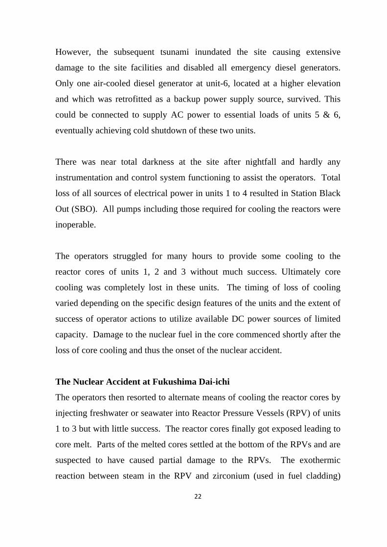
could be achieved by deploying concrete pump trucks, injecting freshwater
from nearby reservoirs after the initial sea water injection.
Radioactive material leaked into the environment during explosions, during
venting of primary containment vessels and also through the water leaked
from the reactor pressure vessels during the continued efforts of cooling the
reactor cores. Based on the quantity of radioactive material released to the
environment, this accident has been rated at level-7, the highest level on the
International Nuclear and Radiological Event Scale.
In order to prevent undue exposures, Japanese authorities decided to evacuate
the population in the 3 km area around the Fukushima Dai-ichi plant on 11
March. This was extended to 20 km on 12 March based on monitoring and
assessments carried out subsequently. On March 15th, the residents living at a
distance of 20 to 30 km were advised to stay indoors for sheltering.
25
In spite of the large releases, there was not a single person seriously affected
by radiation (deterministic effect). In fact monitoring of about 2,00,000
members of the public indicated that nobody received any significant dose
and no radiological health effects are expected.
Restoration work at Fukushima Dai-ichi after the accident
A road map prepared by TEPCO (the owner of the plant) addresses the three
basic safety functions of shutdown, cooling of reactor core and containment
of radioactivity. Boron was added in the water that was injected in the reactor
vessels in the early phase of the accident to ensure long term sub-criticality.
The road map aimed to achieve stable cooling in the first 3 months and a
complete cold shutdown condition within 6 months. The stable cooling,
characterized by stabilizing the Reactor Pressure Vessel (RPV) bottom head
temperature, was achieved by mid-July 2011. Since then, water is being
continuously injected to reactor core at a rate 3-5 m3/hr for sustained cooling.
The spilled water is collected, treated and injected back into RPV. For
achieving the cold shutdown conditions installation of closed loop system
containing pump, heat exchanger and its associated secondary cooling system
is under consideration.
For stable cooling of the spent fuel pools, a closed loop cooling system with
its associated pump, heat exchanger and secondary cooling system has been
installed and made operational for units-1, 2, 3 and 4.
A system of continuous injection of nitrogen gas into the primary
containment (PCV) was implemented in units-1, 2 and 3 to obviate possibility
of another hydrogen explosion. TEPCO is in the process of installing
temporary structural reactor covers on all the affected reactor buildings.

26
Many other short and medium term restoration measures involving
monitoring of reactor parameters, treatment of radioactive water, removal of
debris inside the plant, control of contamination spread in ground water and
sea water, and radiation dose monitoring outside the plant have been
implemented. Long term restoration measures like achieving long term cold
shutdown conditions in all the affected units, installation of permanent reactor
building covers, protection against stress corrosion cracking of the structural
material, installation of supporting structure below the spent fuel pool in unit-
4, remediation of contaminated soil, continuous environment monitoring and
commencement of work for removing the fuel from the core are being
implemented.

27
Annexure-3
AERB REGULATIONS ON NPP SAFETY AGAINST EXTERNAL
EVENTS
AERB was created in 1983 to formally regulate safety in nuclear and
radiation facilities in the country. Over the years AERB has evolved a robust
procedure for safety review and issue of consents at various stages of setting
up of these facilities in line with the best international practices and IAEA
guidelines. The main consenting stages for nuclear power plants are siting,
construction, commissioning, operation and decommissioning. At each stage
a comprehensive review in a multitier structure of safety committees is
carried out before issue of consent.
AERB’s safety review process
The basic safety philosophy of defense-in-depth is followed in the design of
nuclear power plants (NPPs). Important features of this philosophy are
overlapping provisions in design and operation to prevent plant failures,
detection and intervention of any failures should they occur, provision of
multiple barriers against radioactivity releases, and mitigation of the
radiological consequence through emergency procedures in case of any
releases. All operating plants undergo a periodic safety review (PSR) to
address changes in safety standards, ageing effects, and operating experience
feedback including those pertaining to external events.
Design of 220 MWe Indian PHWR based NPPs was standardized from NAPS
onwards. The currently operating PHWR plants based on this standardized
design are NAPS-1&2, KAPS-1&2, KGS-1 to 4 and RAPS-3 to 6. TAPS-
3&4, though based on the basic features of standardized Indian PHWR, has

28
been designed to produce 540 MWe. The standard design, which has several
improved design safety features, has undergone rigorous safety review. For
example, these plants are provided with two failsafe independent and diverse
shutdown systems to achieve guaranteed reactor shutdown state with very
high reliability, besides reactivity control through reactor regulating system
for normal operation. The concrete vault housing the calandria (reactor
vessel) is filled with water. This provides a large heat sink against progression
of any accident caused by loss of coolant. Availability of large volume of low
pressure moderator in the calandria is also an inherent advantage for core
cooling in case of an accident.
All the standardized PHWR based NPPs are provided with double
containment with inner primary containment of prestressed concrete acting as
a primary barrier against release of any radioactivity to the atmosphere in the
event of an accident. The primary containment is designed conservatively to
withstand a pressure much higher than that estimated during the postulated
design basis accident. Thus it can prevent releases even in case of certain
level of beyond design basis accidents.
For the plants constructed before NAPS (viz. TAPS-1&2, MAPS-1&2,
RAPS-1&2), significant safety improvements have been carried out through
back-fits and safety upgrades based on periodic safety reviews and special
reviews conducted when these NPPs were approaching the end of their
originally proclaimed design life. Major improvements are related to seismic
safety, emergency core cooling and ageing management.
India has also witnessed a few significant events at its NPPs, namely a large
fire at NAPS in 1993, flooding at KAPS-1&2 in 1994, delamination of the

29
inner containment dome during prestressing operation in Kaiga-1 in 1994 and
tsunami at MAPS-1&2 in 2004. Lessons learnt from these events as also
from relevant events at NPPs abroad have been incorporated by appropriate
improvements in design and operating procedures.
Safety regulations
The major safety regulations of AERB are issued in the form of safety
standards comprising of safety codes and safety guides. Developing and
updating of safety regulations is a continuing process at AERB. For NPPs,
the safety regulations structure corresponds to various stages of consenting,
namely siting, design & construction, commissioning, operation and
decommissioning. Besides this, standards on the regulatory process have been
issued to lay down procedures for issue of consents, design and operational
safety review, regulatory inspections, and also for development of safety
regulations. Assurance of quality in each of the activities pertaining to NPPs
during their life cycle is institutionalized through another set of regulatory
standards.
The regulatory standards in India are developed with safety concepts,
requirements and methodologies derived from IAEA safety standards and
other international nuclear safety regulations, which collectively represent
enormous experience in design, construction and operation of NPPs.
AERB follows a three tier system of regulatory standards. Safety codes
establish the objectives and set the requirements to be fulfilled to provide
adequate assurance for safety. Safety guides elaborate on the requirements
specified in the codes and describe the approaches for their implementation.
Safety manuals deal with specific topics and include detailed scientific and

30
technical information on the subject. These standards are prepared by experts
in the relevant fields and are extensively reviewed by advisory committees of
AERB before their publication. The standards are periodically reviewed and
revised as necessary, in the light of experience and feedback from users as
well as new developments in the field.
The list of regulatory standards developed by AERB is exhaustive covering
all facets of nuclear power plant safety and is available on AERB website. A
selective list of standards pertaining to NPP safety against external events is
given below.
AERB Safety standards on NPP safety against External Events
S.No. Identification Number Title 1. AERB/SC/S Code of practice on safety in Nuclear Power
Plant Siting 2. AERB/SG/S-1 Meteorological Dispersion 3. AERB/SG/S-2 Hydrogeological dispersion – methodology
and modelling 4. AERB/SG/S-3 Extreme values of meteorological
parameters 5. AERB/SG/S-4 Hydrogeological considerations of NPP
siting 6. AERB/SG/S-5 Principles of control of exposures in public
domain 7. AERB/SG/S-6A
AERB/SG/S-6B Flooding and flood analysis a) Inland flooding b)Coastal sites
8. AERB/SG/S-7 Human induced events and establishment of design basis
9. AERB/SG/S-8 Influence of site parameters on emergency preparedness
10. AERB/SG/S-9 Population distribution and its analysis 11. AERB/SG/S-10 Quality Assurance in Siting 12. AERB/SG/S-11 Seismic Studies and Design Basis Ground
Motion for Nuclear Power Plant Sites
31
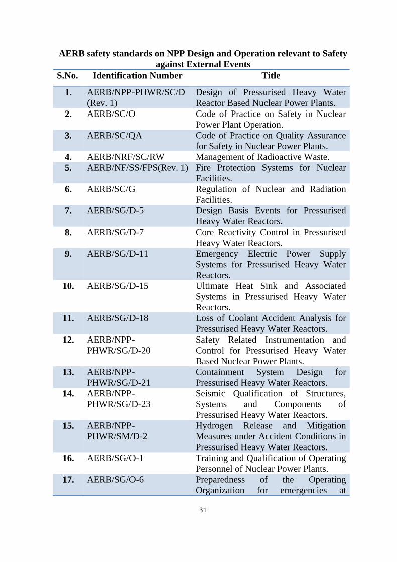
AERB safety standards on NPP Design and Operation relevant to Safety against External Events
S.No. Identification Number Title
1.
AERB/NPP-PHWR/SC/D (Rev. 1)
Design of Pressurised Heavy Water Reactor Based Nuclear Power Plants.
2. AERB/SC/O Code of Practice on Safety in Nuclear Power Plant Operation.
3. AERB/SC/QA Code of Practice on Quality Assurance for Safety in Nuclear Power Plants.
4. AERB/NRF/SC/RW Management of Radioactive Waste. 5. AERB/NF/SS/FPS(Rev. 1) Fire Protection Systems for Nuclear
Facilities. 6. AERB/SC/G Regulation of Nuclear and Radiation
Facilities. 7. AERB/SG/D-5 Design Basis Events for Pressurised
Heavy Water Reactors. 8. AERB/SG/D-7 Core Reactivity Control in Pressurised
Heavy Water Reactors. 9. AERB/SG/D-11 Emergency Electric Power Supply
Systems for Pressurised Heavy Water Reactors.
10. AERB/SG/D-15 Ultimate Heat Sink and Associated Systems in Pressurised Heavy Water Reactors.
11. AERB/SG/D-18 Loss of Coolant Accident Analysis for Pressurised Heavy Water Reactors.
12. AERB/NPP-PHWR/SG/D-20
Safety Related Instrumentation and Control for Pressurised Heavy Water Based Nuclear Power Plants.
13. AERB/NPP-PHWR/SG/D-21
Containment System Design for Pressurised Heavy Water Reactors.
14. AERB/NPP-PHWR/SG/D-23
Seismic Qualification of Structures, Systems and Components of Pressurised Heavy Water Reactors.
15. AERB/NPP-PHWR/SM/D-2
Hydrogen Release and Mitigation Measures under Accident Conditions in Pressurised Heavy Water Reactors.
16. AERB/SG/O-1 Training and Qualification of Operating Personnel of Nuclear Power Plants.
17. AERB/SG/O-6 Preparedness of the Operating Organization for emergencies at

32
Nuclear Power Plants. 18. AERB/SG/O-9 Management of Nuclear Power Plants
for Safe Operation. 19. AERB/SG/O-10 Core Management and Fuel Handling
for Nuclear Power Plants. 20. AERB/SG/O-13 Operational Safety Experience
Feedback on Nuclear Power Plants. 21. AERB/SG/EP-1 Preparation of Site Emergency
Preparedness Plans for Nuclear Installations.
22. AERB/SG/EP-2 Preparation of off-site Emergency Preparedness Plans for Nuclear Installations.
Safety against external events of natural origin
The AERB Safety Code on design of PHWR based NPPs stipulates that
structures, systems and components necessary to assure the capability for
shutdown, residual heat removal and confinement of radioactive material
shall be designed to remain functional throughout the plant life against
postulated natural events. Design basis for the structures, systems and
components shall include:
(i) Consideration of the highest specified intensity of the postulated
natural events or other external events; and
(ii) Consideration of the radiological consequences of such events.
Details of design basis external events that need to be considered are
described in the AERB code on safety in NPP siting. The siting code
stipulates that site characteristics, which may affect the safety of the nuclear
power plant, shall be investigated and assessed. Proposed sites shall be
examined with respect to the frequency and the severity of external events
and phenomena that could affect the safety of the plant. For an external event
(or combination of events) the choice of values of the parameters upon which

33
the plant design is based should be such as to ensure that structures, systems
and components important to safety in relation to that event (or combination
of events) will maintain their integrity and will not suffer loss of function
during or after the design basis event. If, after thorough evaluation, no
engineering solution can be found to provide adequate protection against
design basis external events, the site shall be deemed unsuitable for locating a
nuclear power plant of the type and size proposed. Design bases shall be
derived for each identified external event by adopting appropriate
methodologies presented in relevant safety guides.
Historical records of the occurrences and severity of the important natural
phenomena shall be collected for the region. The data shall be carefully
analyzed for reliability, accuracy and completeness. If data for a particular
type of natural phenomenon are incomplete for a particular region, then data
from other regions which are sufficiently similar to the region of interest may
be used in the formulation of the design basis event.
Based on data of historical seismicity, the code IS 1893 published by Bureau
of Indian standards has divided India into four seismic zones (zone II to zone
V) with higher zone numbers denoting increasing levels of seismic hazard. As
per AERB requirements, no NPP shall be located at a site that falls in seismic
zone–V, which has a potential to generate earthquakes beyond Magnitude-7.
In addition, it is also verified that no earthquake generating faults are located
within 5km radius of the site.
For evaluation of design basis ground motion for NPP, site specific studies
are carried out within a region of 300 km. These include collection of
information on historical seismicity, earthquake generating faults/areas,

34
possibility of reservoir induced seismicity etc. Field investigations are carried
out by expert agencies like Geological Survey of India. The level of detail of
investigations increases as the location of investigation nears the site.
Design basis ground motion in all operating NPPs in India, from NAPS
onwards have been arrived at following the above stated methodology, which
is considered to be reasonably conservative. The older generation nuclear
power plants, viz TAPS 1&2, RAPS 1&2, and MAPS 1&2 have been re-
evaluated in recent years with respect to the site specific ground motion as
applicable to new NPPs. Based on the findings, the structures, systems and
components have been modified/ strengthened as necessary. These include
provision of new emergency diesel generator buildings, modifications of
battery banks, strengthening of masonry walls etc.
Flooding potential at an NPP site and the related hazards to be considered in
design depend on whether the NPP site is inland or coastal. For a coastal site,
the design basis flood level is estimated considering maximum tsunami wave
height or the combined effect of a cyclone and rainfall. It is also assumed that
cyclone or tsunami is coincident with the maximum tide level. The estimated
flood level is summation of the maximum tide level, the maximum of storm
surge or tsunami level and wave run-up. Various parameters of cyclone
(radius, speed, pressure drop, etc) are chosen such that the flood levels
estimated would have a mean recurrence interval of 1000 years or above.
AERB guidelines for flooding due to tsunami were based on historical data of
tsunami wave heights prior to the 2004 Indian Ocean tsunami event. A value
of 3m for tsunami wave height was specified for the west coast north of
Karwar and 2.5m for east coast and rest of the west coast south of Karwar.

35
Though flood levels at NPP sites on the east coast due to 2004 tsunami were
lower than these estimated design basis flood levels, AERB recognized the
need for a more rigorous treatment of tsunami hazard for coastal NPP sites.
For example, for the recently cleared NPP site for KKNPP units-3 to 6,
assessment of worst case scenario from various tsunamigenic sources, as
applicable to the site, was done as per AERB requirement.
For an inland site, the hazards to be evaluated include probable maximum
flood in the water body near the site along with maximum rainfall, and, flood
caused from failure of any upstream dam. The value of probable maximum
flood is chosen such that the mean recurrence interval of the flood is 1000
years or above. Conservatively formulated AERB guidelines exist for detailed
evaluation of the flood hazard at inland sites.
36
Annexure- 4
COMMITTEE’S WORK PLAN
The following plan was developed for the work to be done by the various
expert working groups and review by the committee.
1. Review the postulated design basis external events of natural origin, as
given in AERB safety regulations, to determine whether their magnitudes
require any revision.
2 Suggest the magnitudes that could possibly be used as guidelines for
beyond design basis situations, where possible.
3. Examine the structures, systems and components (SSCs) of existing NPPs
to withstand the intensity of external events in terms of maintaining their
integrity, as determined in 1 and 2 above.
4. Check adequacy of provisions for the following in operating NPPs in case
of external events of maximum postulated intensity.
(a) Capability to shutdown and maintain the reactor in shutdown state.
(b) Capability to maintain reactor containment integrity.
(c) Capability to adequately cool the reactor core on a sustained basis.
Ensuring availability of class 1,2 and 3 power supplies
Availability of relevant equipment and components like DGs,
pumps, piping and valves
Availability of control equipments
Availability of water in required quantities
Availability of ultimate heat sink
(d) Capability to adequately cool the reactor core under station black out
condition.
5. Safety of irradiated fuel in spent fuel storage pools.

37
6. Safety of other facilities at the NPP site that have a potential for release of
radioactivity or spread of radioactive contamination like, near surface
radioactive waste storage facilities and heavy water upgrading plants.
In addition to the areas identified in the work plan given above, the
committee decided to bear in mind the following areas also based on the
various discussions:
i) Severe accident management guidelines (SAMG) should be developed,
duly accounting for postulated accidents initiated by beyond design basis
external events.
ii) Combination of related natural events like earthquake and tsunami/flood
should be taken into account.
iii) Secondary effects of the external events like flooding of operating areas
or fire breakout, wind/flood induced missiles, disruption of transport and
communication need to be taken into account.
iv) A major earthquake is generally followed by a number of aftershocks.
The design of SSCs including engineered safety features as well as
SAMG need to take the aftershocks also into account.
v) PSAs for external events should be undertaken to identify cliff edge
effects and measures for dealing with them.
vi) Capability of the plant to withstand beyond design basis external events
(BDBEs) should be examined in the safety analysis.
vii) The concept of ‘Dry site’ i.e. protection against flooding by adopting
high safe grade level rather than by flood protection measures like
bunds/dykes etc., should be preferred for new NPPs.
viii) Safety assessment should include common cause failure in multiple units
at the same site.

38
ix) Tsunami warning should be available to NPPs at coastal sites through
active tsunami warning systems.
x) Source models and methodologies for estimation of seismic and tsunami
hazards need to be revisited in the light of Fukushima events.
xi) Safety against external events should form part of PSRs.
xii) There should be provision of a shielded and seismically qualified on-site
emergency facility at each NPP site, well equipped for obtaining
information on plant parameters and for communication with relevant
agencies to decide on the course of action in the event of an accident.
These facilities should also have provision of food and rest for the
occupants for about one week.
xiii) Design provisions should be made in all NPP units for preventing
hydrogen explosions in case of a core damage accident.

39
Annexure-5
SUMMARIZED INTERIM REPORTS OF WORKING GROUPS
1. Expert group to review external events in relation to the safety of
nuclear power plants
General
The magnitude 9.0 Tohoku Earthquake (Japan) and the associated tsunami
brought into limelight the need for developing methodologies to derive
parameters for NPPs corresponding to beyond design basis extreme events.
The AERBSC-EE constituted an Expert Group for review of external events
with the following terms of reference.
1. Review the list of postulated design basis external events of natural origin
for completeness and examine their magnitudes, as given in current AERB
safety documents, to determine whether these require any revision
2. Suggest the magnitudes of Beyond Design Basis External Events that
should be used as guidelines, where possible
3. Propose guidelines for deciding on safe grade levels for new NPP sites
4. Examine adequacy of the current methodologies for evaluating integrity of
the existing structures, systems and components (SSCs) of NPPs to
withstand external events, both within and beyond design basis, and
suggest revision/modification, as appropriate
The Expert Group examined the current methodologies for estimation of
design basis parameters and design approaches followed for NPPs.
Parameters to define beyond design basis extreme events are proposed, where
possible at this stage. In cases like probable maximum flood in inland sites,
the estimation depends on several site specific parameters. In such cases a
general guideline is proposed for arriving at the site specific estimates.
40
Earthquake
Current approach
Assessment of seismicity and related hazards constitute a major part of the
siting criteria for NPPs. The Indian Seismic design Code [IS:1893, 2002]
groups the country into four seismic zones. Zone V is associated with the
areas of maximum seismicity and zone II with the minimum. As per AERB
siting code, AERB/SC/S, an NPP is not allowed to be located in zone V.
Potential for ground rupture is also assessed during site evaluation. Presence
of a fault in the vicinity of the site increases the chance of ground rupture
during an earthquake. Hence, if there is an evidence of an active or a capable
fault within 5km of site, the site is deemed unacceptable. Similarly, sites
prone to liquefaction (an earthquake related phenomena) are also rejected
during site evaluation.
Adequate precaution is taken at detailed design stage to ensure that SSCs of
an NPP are capable of withstanding the effects of vibratory ground motion
arising from strong earthquakes derived from study of site characteristics. The
design basis ground motion (DBGM) for this purpose is evaluated for each
site.
The DBGM is derived for two levels of earthquakes, S1 or Operating Basis
Earthquake (OBE) level and S2 or Safe Shutdown Earthquake (SSE) level.
SSE represents the maximum potential vibratory ground motion that can be
expected for the region (with mean recurrence interval (MRI) of the order of
10,000 years). In the event of this level of earthquake, the considerations are
to shutdown the reactor, keep it under shutdown condition, including removal
of decay heat and containing postulated radioactive release within
containment structure. Hence the safety systems, needed to meet these

41
requirements, are designed for SSE level of earthquake. Another vibratory
ground motion, OBE, (with MRI ~100 years) is also specified. All plant
systems, including those for normal operation, are expected to continue to
function when subjected to OBE. If the plant experiences ground motion
above this, it shall be shutdown and inspected. These motions are expressed
by appropriate parameters such as site specific response spectra for various
damping factors, time history and its duration.
For estimating the DBGM parameters of a site, the earthquake sources (e.g.,
faults) around the site need to be identified and maximum earthquake
potential of each source need to be estimated. This is achieved by conducting
a detailed investigation of geological, tectonic and seismological environment
of the site. The data on recorded historical and pre-historical seismicity are
also collected.
The investigations are conducted in four scales, regional (300 km minimum),
intermediate range (50 km radius), local (5 km radius), and site area (within
plant boundary). Each set of study leads to progressively more detailed
investigation resulting in large volume of data and information as it gets
closer to the site. The investigations are carried out through specialist
agencies in the field like Geological survey of India (GSI). The areas are
investigated through satellite imageries, aerial photographs, detailed maps to
determine tectonic structures that could be considered as the sources for
earthquakes. The historic earthquake data available in earthquake catalogues
and any other sources are also collected.
For estimation of ground motion corresponding to S2 level, the maximum
potential of each fault is estimated. This also takes into account the
maximized value of historical/recorded seismicity attributable to the fault, by

42
increasing the recorded magnitude by at least one intensity equivalent for
calculation of ground motion. Subsequently, this maximized earthquake is
brought to the point on the fault which is closest to the site and for this
magnitude and distance combination, earthquake acceleration is determined.
The exercise is repeated for all other faults surrounding the site and the
maximum of acceleration arrived at from all these faults, is adopted as design
basis S2 level acceleration.
Detailed guidelines for derivation of S1 and S2 level ground motions
including PGA, and response spectra are given in AERB guide AERB/SG/S-
11.
Expert group deliberations
SSE level event
The Expert group (EG) discussed the existing method of deriving safe
shutdown earthquake and no significant shortcomings could be noted in the
method. However, the EG recognized limitations of the method because of
lack of sufficient and relevant earthquake data and other uncertainties
regarding site tectonics. These limitations and possible means of alleviating
these were deliberated as follows:
In peninsular India, scarcity of tectonic and historical earthquake data is a
major challenge for defining the earthquake potential. Earthquake events on
many faults have not resulted in manifestations on earth surface. Some major
faults are embedded well below the upper strata that are several kilometers
thick; only sub-features from such fault propagate towards the surface. There
are difficulties in quantifying the seismic hazard because of the limitations of
data and uncertainties in defining the seismic sources. Hence the following
aspects need to be kept in mind while assigning the SSE level event.
43
1. All possible sources of data should be consulted in preparing the tectonic
map of the region. DELPHI method (or weighted expert opinions) may be
employed to arrive at the final recommendation
2. All lineaments shall be examined to identify faults. All mapped faults
should be considered as capable, unless proven otherwise following well
established procedures. A procedure needs to be arrived at for
ascertaining whether fault is active or capable or not.
3. The attenuation relations shall correspond to the tectonic and geologic
characteristics of the region.
4. The ratio of vertical acceleration to the horizontal (presently being
considered as 2/3) can be un-conservative, especially in near field events.
This ratio is frequency dependant, and an estimate of this ratio can be
derived from the existing attenuation relationships.
The Expert Group recommends that the above aspects should be considered
while revising the AERB guide on seismicity so that the concerns are
appropriately addressed.
Beyond Design Basis Earthquake Event
The Fukushima earthquake event has highlighted that the safety of NPPs need
also to be assessed for beyond design basis events of natural origin like
earthquake and tsunami. The Expert Group considered the following
approach to have a reasonable level of such beyond design basis extreme
event for safety assessment.
As with SSE, estimating a beyond design basis earthquake event for an NPP
site in India is a challenging task because of the shortcomings in the data, as
enumerated below:

44
(1) Lack of paleoseismic data on slips at faults on which earthquakes are
known to have occurred in the past and reliable slip rates associated with
each fault;
(2) Lack of statistically sufficient records of historic earthquake,
instrumented data from M>5 events in the recent decades and
attenuation relations for each region in the country, especially in
peninsular India;
(3) Lack of correlation of epicenters with faults/lineaments; and
(4) Some faults that do not have surface features may be missed
Therefore a postulated beyond design basis earthquake event may be used for
assessing the safety margin of existing NPPs and of the new NPPs. This could
be arrived at based on a comparative study of ground motion parameters
derived from:
a) A postulated level of expected maximum acceleration/intensity of
shaking at site, guided by the regional seismicity and local soil/rock site
conditions, irrespective of earthquake source location, and
b) Maximization of earthquake hazard as evaluated following the procedure
for SSE level earthquake.
Further work and discussion on estimation of postulated beyond design basis
earthquake event following both methodologies is in progress.
Flood hazard
Current approach
External flooding is one of the important natural events that have potential to
induce common-mode failure in an NPP. Generally NPPs are safe guarded

45
against external flood hazard by having finished ground level of the plant
above the design basis flood level (DBFL). In some cases, protection
structures are built around the plant site to safeguard against DBFL.
The regulatory requirements for safety of an NPP in India in relation to
external flooding hazard are outlined in AERB Safety Code [AERB/SC/S,
1990]. The sites are generally categorized into two types, coastal site and
inland site. The Code provides requirements for both types of sites.
Similarly, Safety Guides are published by AERB to elaborate requirements of
the Code including methodology for assessment of hazard due to external
floods. The guides allow use of probabilistic or deterministic approaches for
arriving at the design basis flood for NPP sites. While following probabilistic
approach, the design basis flood is calculated for a 1000 year mean recurrence
interval of occurrence of the causative phenomena (viz. precipitation, storm,
etc). While following deterministic approach, the biggest historical storm in
the region is transported to the site area and is oriented in such a way that it
maximizes the flood in the river or storm surge in the sea. Based on the
estimated storm or flood, the design basis flood level at site is estimated with
the use of detailed numerical models. Expert government agencies like
Central Water Power Research Station, Central Water Commission, carry out
this assessment.
For inland site, the flooding could occur due to flood in the adjoining
river/lake, upstream dam break or intense precipitation in the surrounding
region. The failure of the upstream dam/weir may result from seismic or
hydro-geological causes or from faulty operations of these structures or
channel obstruction due to landslides, log or debris jams, etc. Guidelines for
evaluation of probable maximum precipitation and flooding due to failure of

46
water control structures are covered in AERB/SG/S-6A. If the site is on the
bank of inland water body such as reservoir or lake, the effect of seiches (long
period vibration of water body induced by earthquake) is to be considered in
determination of DBFL. In addition, simultaneous occurrence of intense
precipitation in the local site could cause local flooding. The adequacy of site
surface drainage to cater to this demand is also verified.
For a coastal site, the flooding hazards include those caused by cyclonic
storms, tsunamis and local intense precipitation. Guidelines for evaluation of
flooding due to cyclonic disturbance in coastal sites are covered in
AERB/SG/S-6B, which allows use of probabilistic or deterministic estimation
of design basis flood level due to storm surge. In the deterministic method a
set of maximised hypothetical storms are considered, selected and moved to
the location critical for formation of a surge at the site. It is then used as input
for an appropriate numerical model for surge calculation. It is assumed that
the maximum historical tide level is coincident with the storm surge and
values of the maximum tide, storm surge and wave run-up are added to arrive
at the worst estimate of flood level above reference level (generally mean sea
level) during cyclonic storms.
The design basis levels for tsunami are specified in AERB/SG/S-11 (1990).
The guidelines provided were based on the historical data. As per this guide,
Indian coast was divided into two regions, locations above Karwar on west
coast and locations below Karwar including east coast. The specified tsunami
heights were 3m and 2.5m respectively for these regions. The levels due to
the maximum tide and wave run-up were to be added to this height to arrive
at the design basis flood level due to tsunami.
47
Though flood levels due to 2004 tsunami were lower than the estimated
design basis flood levels for the NPP sites, AERB recognized the need for a
more rigorous treatment of tsunami hazard for coastal NPP locations. In order
to ascertain the maximum hazard that could be posed by tsunami to a site,
expert inputs from many national agencies, like Geological Survey of India,
National Geophysical Research Institute, Center Water Power Research
station, Indian Institute of Technology Kanpur, and Indian Institute of
Technology Madras were taken. Based on the discussions, the postulated
tsunamigenic sources and corresponding scenario events (some even bigger
than the 2004 event) were estimated.
Expert Group Deliberations
The expert group reviewed the existing AERB guidelines for flood hazard
assessment. It was noted that no major pitfalls exist in procedures followed
for estimation of design basis flood levels except in case of tsunami hazard
assessment. It was noted that in AERB guide, the recommendations were
based on some data prior to 1990. The EG noted that AERB has initiated
actions towards more rational estimation of tsunami hazard based on
numerical evaluation of tsunami wave heights arrived at from maximum
potential tsunamigenic sources around Indian coast. As regards the existing
methodologies of estimating DBFL, the EG noted that some statistical models
were used in past for rainfall prediction irrespective of their fitness to the site
specific data. Uncertainties in the estimates were also not addressed
systematically. In view of this, the following recommendations were made
by the EG with regard to evaluation of flood hazard.
Evaluation of design basis flood

48
1. The analysis of site specific rainfall data indicates wide variations in the
trends shown by each data. Hence, there is a need for qualification of
probabilistic models with respect to the data before using the same. In
addition to statistical models currently covered in AERB guide (Gumbel
and Frechet), log Pierson type-3 distribution may also be considered for
statistical analysis of data.
2. The assessment of flooding shall be with respect to a mean + 1 sigma
estimate of rainfall, corresponding to 1000 year return period using
appropriate probabilistic models.
3. Irrespective of the return periods used in estimation, some natural
phenomena/parameters have physical upper bounds. Existence of such
deterministic upper bounds, if any, shall also be taken into account in the
evaluation.
4. While assessing inland sites, scenario involving combination of flood
due to dam break and earthquake should be considered.
Assessment of Beyond Design Basis Flood
A site specific analysis needs to be conducted in all plants with respect to the
beyond design basis extreme event to assess the extent of flood hazard with
the parameters defined below. The phenomena/numbers should be revised
and reviewed by appropriate expert groups in project mode so that the gaps in
current assessment can be addressed. The interim recommendations, which
can be considered as possible guidelines for reasonable quantification of
beyond design basis level of extreme flooding events for NPP assessment at
this stage, are as follows:
Inland Flood

49
• In case of flooding caused due to dam break, the postulation (size, extent
and duration) and assessment involves uncertainties and therefore a
conservative upper bound analysis is suggested for beyond design basis
extreme event of dam break along with a rainfall/flood of 100 year return
period
• Analysis of past rainfall data of Mumbai city and three NPP sites,
Tarapur, Kakrapara and Rajasthan, shows that a 15% increase in design
basis rainfall ( i.e. mean + one standard deviation corresponding to 1000
years return period) leads to a rainfall event of over 10000 years return
period (i.e. one order higher event). Therefore, the volume/flow
considered for extreme flood assessment during design basis conditions in
Inland sites (i.e. value corresponding to mean + one standard deviation
estimate for 1000 years return period) may be increased by 15% to arrive
at a first order estimate of flood levels for inland sites as well as for
carrying out the capacity assessment of site drainage corresponding to an
extreme event.
Coastal flooding
• The EG looked into the available data for past storms. Based on these
data, it recommended that a pressure drop of 100 milli bar, associated
wind speed of 300 kmph for east coast and 240 kmph for west coast and
radius of 50 km may be taken as an upper bound value for the postulated
beyond design basis cyclonic storm. The translational speed of storm may
be considered as 40kmph. The total height of the wave shall be summation
of (a) tidal variation, (b) storm surge height, (c) wave set up and (d) wind
induced wave run-up.
Tsunami hazard
50
• Major contribution of tsunami hazard to NPP sites arise from Burma-
Andaman-Sunda region and Makran coast of Pakistan with some local
tsunamis reported near Chagos ridge/Nascent zone in Indian Ocean.
• The faults associated with Carlsberg ridge on Owen Fracture Zone are
transform faults and earthquakes in the region are generated due to strike
slip mechanism. Though large number of earthquakes occurred in this
fracture zone, no tsunamis had been reported and no large earthquakes had
occurred. Hence, tsunamigenic potential of these sources is considered
very insignificant.
• The tsunamigenic zone along east coast of India (viz Burma-Andaman-
Sumatra region) is more than 1300km away from nearest NPP site
(Madras/Kalpakkam). Similarly, the tsunamigenic zone along west coast
(viz. Makran region near Pakistan) is about 800 km away from Tarapur.
Hence, unlike in Japan, NPPs along Indian coast would be subjected to
either a local earthquake or a tsunami caused by a far away earthquake.
• The submarine faults/lineaments located near to the coast are small in
nature and does not have the capability to produce large vertical
displacements that are tsunamigenic in nature. In view of this, there is
hardly any possibility of near source tectonic tsunamis hitting NPP sites.
• A detailed site specific analysis using a validated numerical model shall be
carried out to arrive at accurate estimates of tsunami run-ups under all
possible combinations and variations of input parameters. The evaluation
shall include accurate near-shore data.
As an interim estimate, median values of tsunami heights calculated from
tsunami simulation study for east coast of India based on maximum
possible magnitude of tsunamigenic earthquakes sources and maximum
possible variations of parameters defining earthquake source mechanisms

51
are considered. Median values of simulated tsunami heights (with respect
to mean sea level) at Kalpakkam site range from 6-8m where as at
Kudankulam site it is about 4m. In Tarapur, the predicted median tsunami
wave heights generated from Makran source are less than 2m. However, it
may be noted that possible contribution from a co-seismic land slide may
have to be taken into account for assessments carried out for Makran
source. Therefore, in the interim, the tsunami height value of 3m (as
suggested in AERB guide SG/S-11) may be considered appropriate for
margin assessment of NPPs along the West coast of India. The tidal
variations, as applicable for each site shall be considered while evaluating
the total height due to tsunami.
• For a multi-facility site, plant specific modifications like protection walls
may cause modification of impact of phenomenon on the neighboring
areas. A global analysis that ascertains impact on all facilities shall be
conducted before implementing any protection measures.
• In some locations, shore line bathymetry may be such that it causes very
high amplifications in wave amplitudes. This shall be appropriately
considered and if necessary, the site should be engineered against tsunami
hazard.
Other Meteorological Hazards
For purpose of design of NPPs, wind and temperature constitute major
meteorological parameters that can have an impact on design. Majority of
structures in an NPP have lateral dimensions comparable to their heights and
lateral forces due to earthquake generally governs the design. However, in
slender structures like stack, wind could govern.
The Fukushima earthquake event has highlighted that the safety of NPPs need
also to be assessed for beyond design basis events of natural origin like

52
earthquake and tsunami. In this respect, the possible upper bound parameters
that could be associated with beyond design basis extreme meteorological
phenomena were also deliberated.
Wind
Current approach for design basis wind
Two levels of wind effect are considered during design of NPPs, namely (a)
Severe Wind, and (b) Extreme Wind. The Severe Wind is postulated to be that
event having a return period of 1,000 years, and the Extreme Wind of 10,000
years. NPP structures are designed for severe wind velocities. The extreme
wind velocities are used to assess whether wind induced missiles could be
generated at an NPP site and if so then their effects on items important to
safety are also evaluated. Wind velocities corresponding to both categories
are calculated using probabilistic approaches using site specific data and/or
code of practice for wind loads published by Bureau of Indian standards
(BIS-875, part-3, 1987)
The EG considers the procedures followed for estimation of design basis
wind speed adequate. It was also opined that for the current need of defining
beyond design basis extreme events, it may be considered that the parameters
defined for each phenomena already includes/absorbs the effect of climate
change.
Assessment of beyond design basis wind
The EG looked into the past data on extreme winds in the country and
recommended, based on judgment for a first order estimate, that a beyond
design basis extreme wind speed may be postulated corresponding to 1000
year return period increased by 50% and rounded off to nearest 10m/s speed.

53
The site specific values may be arrived at using the relevant procedures
brought out in IS 875.
Temperature
Current approach for design basis temperature
Extreme temperature in atmosphere could create thermal stresses in
structures. In addition, this could also impact the performance of systems that
use air as ultimate heat sink. At present, no specific requirements exist with
regard to the design basis values to be adopted for atmospheric temperature
during design of structures, systems and components. However, the mean + 1
sigma estimate corresponding to 1000 year return period is being used in the
design of structures in recent projects.
Assessment of beyond design basis temperature value
For the purpose of structural evaluation of SSC as well as functional
evaluation of safety systems related to ultimate heat sink, with respect to
beyond design basis extreme temperature, (mean + 2 sigma) for higher values
and (mean - 2 sigma) for lower values corresponding to 1000 year mean
return period may be considered as guidelines for beyond design basis value
of temperature.
2. Working group to review safety of TAPS-1&2 against external events
The Working Group (WG) noted that Fukushima experienced natural events,
magnitudes of which were higher than those considered in the design of the
plant. These natural events led to sustained station blackout. WG opined that
similar natural events can be postulated with magnitudes higher than that
considered in the design of the station/ units, to see the capability of the
TAPS -1& 2 units to withstand them. WG observed that AERB SC-EE has

54
constituted a working group to arrive at maximum credible magnitudes of
natural events for different NPPs. Till the time these values are available it
decided considering the following values:
(i) Seismic Event: Design basis value of 0.2g for the safety related
components and systems.
(ii) Tsunami Height: Upto 108’elevation of the plant considering a tsunami
height of 3m for the western coast due to an underwater seismic event
at Makran.
The WG reviewed the capability of the plant SSCs to perform the basic safety
functions of Shutdown, Continued core cooling and Containment under the
seismic and tsunami events. It also observed that station blackout would form
a subset of tsunami event in the present plant configuration and studied the
effect of it as well.
The following engineered safety features were identified for the handling of a
serious event/ accident for achieving the basic safety functions considered
above:
a) Shutdown:
(i) Safety Control Rods:
(ii) Liquid Poison System (Shared - Active System):
b) Core Cooling:
(i) Emergency condenser system (Passive System)
(ii) Low pressure core spray and post incident system (CS&PI)
(Shared - Active System)
(iii) Auto Blow Down System (ABDS)
(iv) Shutdown Cooling System (RHRS)
(v) Emergency Feed Water System
(vi) RBCW and SSW cooling Water systems

55
c) Containment:
(i) Primary and secondary containment structures
(ii) Containment isolation valves
(iii) Emergency Ventilation System
d) Emergency Power Supply System
(i) Emergency Diesel Generators (Class III)
(ii) Station control power supply system (Class II)
(iii) Station Batteries (Class I)
Based on the above the following were analyzed:
Seismic Event:
WG noted that the critical SSCs have been designed to withstand SSE of
0.2g. Hence the SSCs would tolerate a seismic event upto a design basis value
of 0.2g. Seismic re-evaluation of the plant has been carried out during the
safety upgradation activity carried out in 2002-2006 wherein the SSCs have
been evaluated for design basis seismic event. These studies were conducted
as per the methodology prescribed by IAEA safety report series 28.
WG noted that some of the critical components like secondary steam
generators, their supports, steam generator secondary lines, ECCS, Liquid
Poison System etc. have not been included in the seismic re-evaluation
studies conducted as it was beyond the scope of the study as per the IAEA
safety standard used. WG opined that these systems and other support
systems as have been identified by the WG also need to be studied for seismic
withstand capability while examining the beyond the design basis natural
events in the wake of Fukushima accident.

56
The WG also felt that till maximum credible magnitudes of natural events are
available, the capability margins available to withstand beyond design basis
seismic loads may be arrived at by extrapolating the analysis results available
with NPCIL from the earlier seismic re-evaluation studies. Accordingly WG
has requested NPCIL to provide the values of the SSCs identified.
With the above background the WG studied the capability of the plant
systems to withstand a design basis seismic event and fulfilling the basic
safety functions. The reactor will be shutdown by the control rods with the
energy stored in the control rod drive accumulators. Cooling of the reactor
will be possible using emergency condenser, ECCS, CRD feed pumps etc.
Containment isolation function will be achieved by the fail safe containment
isolation valves.
As the SSCs have been designed to withstand the design basis seismic event,
concurrent LOCA was not considered. It was seen that the basic safety
functions will be achieved and capability to feed the reactor also will be
available. Filtered containment venting function will not be available as the
filters are not designed seismically. Table I below gives the fulfillment of the
basic functions and the cope up time available.
Tsunami Event:
The WG studied the capability of the plant SSCs to withstand a tsunami of
height 3m based on the value given in AERB guide for siting (AERB/SG/11).
Considering a tsunami height of 3.0 m the highest water surge level comes to
6.84m above mean seal level, which translates into a plant elevation of 107.63
ft. for TAPS 1&2. Including a conservative margin, it was decided to consider
a total water surge level for tsunami wave upto an elevation of 108’. Based on
this, a Tsunami Vulnerability Chart (TVC) was prepared which lists out
critical equipment along with their elevation and the impact on the safety
functions due to their failure.

57
Due to the elevation of the equipment, many of the systems including Class
III emergency power supply systems will be affected by tsunami. The event
will transgress into a Station Black Out (SBO). The basic safety functions
will be achieved. There will be no feed capability to make up reactor water
level. Core cooling through emergency condenser will be possible for a
limited period. ECCS system will not be available. Filtered containment
venting function will not be available. Table I gives the details of fulfilling of
the basic safety functions and the cope up time available for handling this
event.
Station Black Out:
On Station Black Out conditions, the reactor will be shutdown by the control
rods with the energy stored in the control rod drive accumulators. Cooling of
the reactor for a limited period will be possible using emergency condenser.
Containment isolation function will be achieved by the fail safe containment
isolation valves.
During extended SBO, as indicated above, the basic safety functions will be
achieved. The coping time for the event depends on the emergency condenser
function (8 hrs), reactor water inventory (6hrs) and availability of Auto Blow
Down System (ABDS) to depressurize the reactor for limited number of
operation of RVs and the station batteries service time. Feed capability will
not be available. Filtered venting of Containment will not be available due to
unavailability of power supply to the fans. Table I below gives the fulfillment
of the basic functions and the cope up time available.
Concurrent Failures:
a) LOCA:
As the safety related systems and components are designed for a value of
0.2g, Double Ended Guillotine Break (DEGB) is not likely to occur during a

58
design basis seismic event. Emergency feed capability of 410 lpm (110 gpm)
exists for make up at high pressure (100 kg/cm2) through CRD feed pumps
which are designed for withstanding design basis seismic events.
b) Fire:
Fires can be possible along with a seismic event. The nature and extent of the
fire will affect the recovery actions and the resources available for handling
the external events. The fire protection lines at present are not seismically
qualified. Fixed fire protection system can be used if they survive the external
event. Portable fire extinguishers can also be used. Fire order for handling
the fires is available. The site is serviced by a centralized fire station.
Spent fuel storage:
The spent fuel pool and the components are seismically designed. The water
inventory in the fuel pools will give 9 days of margin before uncovering of
the bundles takes place with the full core unloaded in the spent fuel pools.
However this margin will be considerably reduced if the fuel pool gates
towards the reactor cavities lose their integrity and/ or sloshing takes place
during a seismic event. Worst case calculations for a gross failure of the fuel
pool gates and available water inventory showed a margin of nearly 1.3 days
for the fuel pool storage racks to get uncovered. The fuel pool water make up
capability will be affected by the non-availability of service water or
demineralised water pumps as they are not seismically qualified and also will
be affected by tsunami.
Severe Accident Management:
There are no severe accident management guidelines available for TAPS
1&2. These should be made available based on severe accident analysis.
Conclusion:
The above studies indicate that for all the events considered, shutdown of the
reactors will be achieved by control rods. Limited passive cooling capability

59
exists for six to eight hours using emergency condensers. Containment
isolation capability exists through fail safe isolation valves.
Handling of the events further will depend on the availability of the
equipment/ resources and the approachability of various equipments/
locations during the progression of the events.
The short comings of different SSCs in achieving their intended function
under different postulated scenarios were brought out in the interim report.
Action should be initiated to address these issues.
Table-I Safety Function Capability and Cope up Time for External
Events
Safety
Function
SIESMIC
(0.2g PGA )
TSUNAMI (3.0
m )
(108’ ele)
Extended SBO
Shutdown
(control of
reactivity)
Yes.
(i) SCRAM
through
Control Rods.
(ii) Liquid
Poison System
Available
Yes
(i) SCRAM
through
Control Rods.
(ii) Liquid
Poison System
Not Available
ATWS
mitigation not
possible
(Emergency
Power Supply
Yes
(i) SCRAM
through
Control Rods.
(ii) Liquid
Poison
System Not
Available
ATWS
mitigation not
possible
(Emergency

60
system (EPS) not
available)
Power Supply
system (EPS) not
available)
Core
Cooling
Yes
(i) Emergency
Condenser (8
hrs)
(ii) CRD feed
facility
(iii) ECCS &
ABDS
available
Yes
(i) Emergency
Condenser (8
hrs)
(ii) Reactor Water
Inventory
(6hrs)
(iii)Station
Battery (8hrs)
Following NOT
Available:
Reactor feed
facility,
ECCS, ABDS &
RHR - No
Emergency
Power Supply
Yes
(i) Emergency
Condenser
(8 hrs)
(ii) Reactor Water
Inventory
(6hrs)
(iii)Station
Battery (8hrs)
Following NOT
Available:
Reactor feed
facility &
ECCS, ABDS &
RHR - No
Emergency
Power Supply

61
Containment Yes
Containment
Isolation –Fail
Safe
Filtered Venting
not possible -
Filters Not
designed for SSE
Yes
Containment
Isolation –Fail
Safe
Filtered Venting
not possible. -
Flooding of areas
& No Emergency
Power Supply
Yes
Containment
Isolation –Fail
Safe
Filtered Venting
not possible. -
No Emergency
Power Supply
3. Working group to review safety of PHWR based NPPs under
prolonged station black out and loss of ultimate heat sink
The Working Group (WG) decided to review the following set of events for
all PHWR based NPPs in India.
i. Extended station black out (SBO)
ii. SBO+flood level above design value
iii. SBO+loss of Ultimate Heat Sink
The Working Group interim report is based on the reviews carried out so far
on the operating PHWR NPPs capability to withstand station blackout for at
least 7 days. NPPs capability to withstand multiple failures as listed above
will reviewed in the forthcoming meetings of WG.
All Indian PHWR stations are provided with backup diesel generator sets to
provide class-III power supply to essential station loads in case of off-site
power failure (class-IV). Stations are also provided with class-II (UPS) and
Class-I (battery banks), which cater to very essential loads. These sources
provide power for sufficient period for taking initial actions in case of station

62
blackout (i.e. loss of class off-site and on-site power). With the redundancy
and reliability of DG sets, likelihood of SBO is very rare.
All PHWR NPPs, except RAPS-1&2 have three diesel operated fire pumps.
Provisions exist for injecting fire water to steam generators and end shields
during SBO conditions. In case of RAPS-1&2 two additional diesel generator
of 625KVA were retrofitted to take care of floods caused by Gandhi Sagar
dam break. These are located at higher elevation and will power essential
loads during SBO.
All NPPs have emergency operating procedures for dealing with SBO.
Routine surveillance and testing of diesel fire pumps and flood DGs is carried
out for ensuring their availability. The carbon steel fire water ring header used
for injecting water to SGs, end shields is not covered under any surveillance
programme. Failures in the form of pin holes have been observed in the past
in these lines.
Though SBO is considered as a beyond design basis event, all standardized
PHWR final safety analysis reports have considered SBO and has analysed it
considering crash cool down at the 6th & 30th minute of station blackout to
enable injecting fire water into steam generators secondary side for further
decay heat removal . The analysis indicates that core cooling can be
maintained through thermo-syphoning in both the conditions by injecting fire
water to the steam generators and end shields. In the FSAR analysis is given
for first 24 hours of SBO. It is also seen that temperature of moderator water
and vault water reaches to about 90 & 80 deg C respectively in case of SBO
of 24 hours. The likely temperatures in case of extended SBO beyond 24
hours and their acceptability need to be assessed and addressed accordingly.

63
For assuring continuity of thermo-siphoning, PHT system needs to be made
up if losses due to shrinkage and leakages are high during extended SBO. At
present no dedicated back up provision exists in PHWR stations for PHT
system make-up under prolonged SBO conditions.
Sufficient inventory of water is available at all sites for catering to water
supply requirements of SBO for at least seven days. The diesel fire pumps
can operate for about 7 to 8 hours after which need for replenishment of
diesel will arise. The makeup diesel for the fire water pumps would have to
be done manually, which is possible. The capability of the diesel fire pumps
for continued operation needs to be proved by operating for an extended
period.
For the interim report, the working group concluded that SBO for a period of
7 days may be manageable for all PHWRs without external support, with
respect to fuel cooling, subject to:
i. Induction of quality assurance programme for fire water injection
systems and incorporation of suitable surveillance & ISI activities.
ii. Dedicated provision to inject water from a different source to be
identified and kept ready for maintaining system full on PHT side to
effect continuous thermo siphoning.
iii. Demonstration and maintenance of required logistics to transfer diesel
to fire water pump from main diesel tanks.
iv. Inclusion of appropriate steps in the EOP to take care of non
availability of compressed air and power supplies to I & C, both for
actuation of certain essential valves and indication of process
parameters.

64
v. Alternate means may have to be evolved to limit the moderator and
vault water temperature to be within acceptable limits under prolonged
SBO.
Working group proposes to continue the review of the multiple events of
SBO + beyond design basis flood level and SBO + loss of ultimate heat sink.
4. Working group to review safety of electrical systems of PHWR based
NPPs against external events
Review scope
This Working Group was constituted to examine electrical systems of the
Indian PHWR based NPPs to ensure availability of Class I, II, and III power
supplies to all essential equipment/components in the case of external events
of natural origin, including combination of related events, of maximum
postulated intensity, required for a) Safe shutdown of the reactor and
maintaining it in guaranteed shutdown state b) Adequate cooling of the
reactor core on a sustained basis and for c) Ensuring containment function.
Towards this WG obtained a firsthand knowledge of the current status of the
location of all Class I, II and III Electrical system equipment of the stations
vis-a-vis its requirement under postulated external events such as DBFL,
seismic withstand level etc, its Present condition and the flood proof
condition of cable entry from trenches and tunnels to the building where this
equipment are located in view of various external events postulated form the
respective stations through answers to the queries send by the WG to them in
tabular form and presentations by the stations.
Observations

65
It was tried to assess the margin available at various stations to prevent
flooding of site based on the Design basis flood level and Elevation of DGs,
Class I, II & III equipment of all the operating stations based on the
presentations made by the stations and it is found that margin exists in all the
stations. Similarly DGs, Class I, II & III equipment in the station at this site,
as presented by the site are designed as per Design basis Earth quake level of
each site except in RAPS 1 and 2 where the Design basis Earth quake level
was revised. Subsequently the plant was re evaluated for the new design value
and presently this station qualifies for the new earthquake level.
The effect of earth quake on switch yards and the time within which the
switch yard and hence the class IV power supply can be normalized post earth
quake was also reviewed in the light of the presentations made on the
infrastructure available and various arrangements existing at stations for it.
Stations needs to carry out a detailed study to work out the components in
switchyard vulnerable to earth quake ,spares required to be stored at site and
expertise required for certain jobs to bring back switchyard and the grid on
line subsequent to an earth quake within a short period.
On WG request station conducted walk through to confirm the healthiness
Class I, II and III electrical power supply equipment. In the walk through it
was observed that all the equipment are properly supported and the equipment
presently at location meets the design specifications. WG had requested
stations to confirm that if fire barriers at cable penetrations perform as seal
against flooding then it is required to be confirmed that it is a flood cum fire
barrier and not fire barrier alone.

66
From the presentations made WG has generally observed that Class I, II and
III power supply equipment of all the stations will be available under
presently specified Design Basis Flood Level and Design basis earth quake.
Further work
The committee will review the class I, II and III power supply availability for
beyond design basis accident situation once the parameters to be considered
are identified.
WG has identified a few no. of specific issues pertaining to various stations
which needs to be considered while considering BDBA and it will be
reviewed in the forth coming meetings of the WG.
5. Working group to review safety of control & instrumentation of PHWR based NPPs against external events
The Working Group on C&I was formed to examine the control &
instrumentation systems in Indian PHWRs for their functioning in the case of
external events, including combination of related events of maximum
postulated intensity. The review process adopted by the Working Group
considers the site specific relevance to the external events taking into account
of plants same vintage. Plant specific data on C&I systems was obtained
through a detailed questionnaire, prepared covering five major areas,
• Reactor trip and actuation circuits and associated C&I components along
with monitoring for long term guaranteed shutdown status,
• Instrumentation for ensuring sustained core cooling and its status
monitoring,
• Instrumentation for ensuring containment functions and monitoring of
containment performance,

67
• Displaying important process parameters required during prolonged SBO,
and
• Instruments used for monitoring radiological status within and outside the
plant.
The Working Group on C&I insisted the station/NPCIL to provide data on
C&I systems / components and associated panels about their, location,
mounting and elevation, power supply sources, environmental qualification
and seismic qualification and also fire rating / qualification of cables. Initial
review of plant data from all the PHWRs under operation is completed and it
revealed the following strengths and weaknesses,
(i) Seismic qualifications for typical instruments at newer NPPs (KGS-1
onwards) are in the range of 3 to 3.5 g. For older units tests/analysis was
conducted for some important instruments as well as associated panels at
ECIL. Analysis for older units shows seismic qualification for instruments
in the order of 1 g. Seismic qualification data for Alarm units and Field
Panel are typically in the range of 2.5 g to 2.88g. In general the safe
shutdown earthquakes for Indian NPPs are in the order of 0.1g to 0.3g.
(ii) Environmental qualification includes operability of instruments at
specified temperature, humidity and radiation level if inside RB.
Temperature and Humidity rating for instruments outside RB are
generally 45 to 55 Deg C at 95 RH.
(iii) Sensors necessary for reactor tripping function & instrumentation linked
to moderator and its fire water injection are located inside RB. Hence,
their locations with respect to elevations are not important from flooding
consideration.

68
(iv) I&C related to fire water injection in SGs and ECCs are located outside
RB at 100m EL, which is grade level. The grade levels are above design
basis flood in all the NPPs.
(v) Station battery back-up for control power supplies are adequate for more
than 1 hr without any load cut off, except for RAPS & MAPS, where they
can supply for 30 minutes. But with the shedding of un-important loads as
per station operating procedure, the availability can be extended.
However, there is a need to establish vital parameter monitoring for
prolonged SBOs upto 7 days.
(vi) Some components of the various control power supplies (250V AC/48V
DC/24V DC) are located at 100m El, except for RAPS and MAPS where
they are generally at higher elevation.
(vii) Although availability of COIS/CRCS/PIS is not so important
considering prolonged SBO, their functions with respect to monitoring of
post-accident monitoring of some parameters need to be re-looked.
(viii) The pumps and related C&I used or can be used for sustained core
cooling like ABFP, ECCS are located at 91m elevation, which is below
flood level, but flooding is possible at these areas only after the water
level raises above 100m El. Any water leakages through cable or pipe
penetrations need to be checked.
(ix) Manual cranking of diesel engine driven fire pumps are not always
possible. The availability of starting batteries and chargers become
important during beyond design basis flood. Presently they are located at
100m El (grade level).
(x) Some seismic switch/sensors are outside RB and at lower elevations than
grade level. Water tight enclosures for them need to be ensured.
(xi) Seismic trip is provided only at NAPS. In multi-unit sites like KGS and
RAPS only one unit is having seismic instrumentations, where as other

69
units are sharing the alarm signals. However, NPCIL decided to provide
seismic trip at all the NPPs
(xii) Provisions for post accident sampling of atmosphere inside
containment and important process fluid need to be strengthened further.
(xiii) Although emergency operating procedures (EOPs) available at all the
NPPs, indications available to confirm guaranteed shutdown state of the
reactor under extended SBO (about 7 days) should be re-looked.
(xiv) Backup instrument air accumulators are provided for important
individual valves / instruments. Availability of those accumulators under
a beyond design basis seismic event need to be ensured.
(xv) In RAPS/MAPS, Power and Control battery banks shared. Aspects
related to availability of critical control functions under SBO should be
reassessed.
(xvi) In older plants the supplementary controls rooms (SCRs) were back-
fitted as an abundant safety measure. The control and monitoring facilities
provided at these SCR need to be re-look from point of view of sensor
separation, adequacy of Power Supply, etc. WG felt that the strengthening
of SCR will be easier task than increasing availability of MCR.
The preliminary review conducted for each NPPs by the Working Group were
to check the adequacy of the existing provisions. Further detailed review is
under progress. This WG is dependent on the outcome of other WGs and the
guidance of AERBSC-EE on the following:
• Adequacy of postulated events/combinations to be considered
• SBO duration to be considered
• Maximum postulated intensity of earthquake & flood
• Systems required for Severe Accident Management scenario.

70
6. Working group to review safety of spent fuel storage facilities at NPPs against external events
Scope
The following are the scope of review for WG
a) Capability to adequately cool the irradiated fuel stored in these facilities
on a sustained basis and in this regard, adequacy and availability of the
following as appropriate.
i) Power supply of appropriate class.
ii) Ventilation system to prevent contamination spread.
iii) Equipment and components like DGs, pumps, heat exchangers,
piping and valves
iv) Control equipments and instrumentation
v) Provisions for cooling of fuel and make up pool water level in case
of prolonged station blackout
b) Structural integrity of pools and liners and their leak tightness.
c) Water loss due to sloshing and capability for making up the water level.
d) Stability of fuel storage racks/trays and mechanical handling facilities.
e) Prevention of falling of heavy objects in the pool or on the dry storage
casks.
Observation
WG held a total of five meetings and discussed about the terms of reference,
scope, review approach and methodology to be adopted for systematic and
early completion of review work. WG reviewed preliminary analysis and
calculation results based on the thermal load.
From the analysis results it is observed that,
• The time available before the water level reaches minimum shielding
level for arranging the makeup water supply under the postulated

71
events ranges from minimum 3.9 days (MAPS) to maximum 26.3 days
(NAPS). The studies were done on the basis of the preliminary data
available for the existing plants.
• In case of RAPS- 1&2 and MAPS- 1&2 the emergency preparedness
for makeup water should match the requirement of 3.9 and 5.75 days
respectively.
• The time available before the top layer of fuel bundles is exposed is
16.81 days for RAPS- 1&2, 11.4 days in case of MAPS- 1&2 and for
other reactors it is more than one month.
• WG also observed that the bulk boiling of water starts in as low as 1.9
days (MAPS) to 7 days (NAPS) which may affect the structural
integrity of the pool.
• WG felt that an external water hookup provision for maintaining the
required level in SFSB for all the operating plants should be
implemented irrespective of any other design provision. Make up flow
rate should be commensurate with the water loss due to evaporation.
• WG observed that present monitoring of SFSB water level, temperature
and radiation field may not be adequate during BDBA condition like
Fukushima. Accordingly, suitable passive monitoring/ indication
facility should be provided which will be capable of monitoring the
above parameters.
Preliminary safety assessment on various SFSBs indicates that for decay heat
removal there is no immediate concern in Indian nuclear power plants
(PHWRs) except for RAPS- 1&2 and MAPS- 1&2 as indicated by the
analysis.
Further Work
72
Detailed site specific safety assessment of SFSB with respect to following
will be considered based on the available design information:
Earth quake, tsunami and their combination, Rain water flooding, Dam
break/river diversion leading to flooding, Fire due to hydrogen, Earth quake
induced sloshing, water loss; spread of contamination and make up provision,
Adequacy of power supply for SFSB cooling and its availability during
external events, Effectiveness of ventilation system to prevent spread of
contamination and control of fire due to hydrogen explosion or any other
reason, Stability of fuel storage racks and mechanical handling equipment,
Falling of objects /casks in SFSB.
Man-made external events and certain natural external events which are not
relevant in Indian context are not proposed to be considered.
7. Working group to review safety of heavy water upgrading plants at
NPP sites against external events
The working group reviewed the safety of Heavy Water Upgrading Plant and
Heavy Water Clean-up Facility at Nuclear Power Plant (NPP) sites against
the release of radioactivity or spread of radioactive contamination due to
external events of natural origin including combination of related events of
maximum postulated intensity. The observations of the committee are as
follows:
i) The various systems involved in Heavy Water Upgrading are :
a) Downgraded Heavy water storage & transfer facility
b) Heavy water evaporation & clean-up facility
c) Heavy water Upgrading Plant.
73
During the nuclear reactor operation, heavy water which has leaked from
the reactor moderator system and the Primary Heat Transport (PHT)
system is degraded with impurities in the surroundings. The isotopic
purity of the leaked heavy water comes down. The collected downgraded
Heavy water is stored in tanks of various capacities in the Downgraded
heavy water storage & transfer system. All impurities such as oil, ionic
impurities, dirt etc, are removed in Evaporation & clean-up plant by
filtration, alkaline-evaporation, condensation and ion-exchange unit. In
the Heavy Water Upgrading Plant isotopic purity of downgraded heavy
water is improved to reactor grade by distillation under sub atmospheric
pressure condition.
ii) Building Layout:
a) Downgraded storage tanks of various capacity (250 m3 /180 m3 etc.)
are provided for storage of downgraded heavy water in an RCC dyke.
Capacity of tanks and dyke varies from site to site.
b) Evaporation & Clean-up plant is single storey building. The size &
location of the plant varies from site to site. Generally, clean-up plant,
is located adjoining Upgrading Plant in most of the sites, however in
few sites, the plant is located in Service building. Equipments located
in clean-up plant are small capacity storage tanks, evaporators, filters
etc.
c) Upgrading Plant building is a single storey RCC structure. Two
Distillation columns are housed in a structural steel tower of overall
size 7 m x 7 m x 58 m height. Number of distillation columns also
varies from site to site. Major equipment in the plant is Distillation
column assembly. Each distillation column assembly consisting of
column sump, column sections (14 nos. each), vapour hood – reflux
condenser assembly and re-boiler. Column sump is having 1.4 m
74
diameter and 5.3 m height. Each column section is of 1.05 m diameter
and 3.25 m height. The total height of distillation column assembly of
14 sections including reflux condenser and top vent condenser is 55
meters. The height of structural steel tower housing the distillation
column assembly is 58 meters. Other equipment in the plant are
Storage tanks of various capacity (10 m3 /6 m3/ 3 m3 etc.), pumps,
Motor Control Center (MCC), UGP control panel etc.
iii) Heavy Water Upgrading Plant (UGP) is an auxiliary system to nuclear
power plant and its availability or operation does not have any effect on
power plant operational safety. In case of total power failure after any
external event, the Upgrading Plant will go to safe shutdown mode.
iv) Location of UGP & Clean-up facility with respect to other site structures
varies from site to site. Also downgraded storage capacity and UGP
processing capacity is different at different sites.
v) During sitting, design and construction of facility, the parameters like
site characteristics and to some extent of the external natural events are
taken into account.
vi) These facilities are designed and constructed as per the safety
requirements. An earth quake of considerable magnitude and total
flooding of these facilities will not cause undue radiological impact to
the public as downgraded heavy water is contained in tanks and drums.
Also the Tritium content is expected to be very less due to low Isotopic
Purity (I.P.) of downgraded heavy water. Storage tanks at NPPs are
designed and constructed to meet the requirements of operational basis
earth quake (OBE). The radioactive release from the plant is limited in
view of lower I.P. of downgraded heavy water stored in the system.

75
vii) In case of external events like earthquake, tsunami, flood, cyclone
beyond design level, there can be immediate safety related issues of the
plant or people around it but it will not initiate series of catastrophe.
viii) Further study and analysis of existing building, structure and equipment
specifically tall structural steel tower and distillation column need to be
carried out to assess margins available in the postulated level of
earthquake. This issue is site specific and individual plants are to be
addressed independently rather than in a combined effort based on
location of Upgrading plant and nearby safety structures.
8. Working group to review safety of near surface radioactive waste
disposal facilities and liquid waste storage tanks at NPP sites against
external events
After Fukushima nuclear accident in Japan, AERB has constituted a
Committee to review the safety status of Indian NPPs in case of external
events. AERB-EE Committee has constituted a Working Group to examine
the safety of Near Surface Disposal Facilities (NSDF) and radioactive liquid
waste storage tanks at all NPP sites with respect to the release of radioactivity
or spread of radioactive contamination due to external events of natural origin
including combination of related events of maximum postulated intensity.
The Working Group met on four occasions and reviewed the existing design
and construction features of NSDFs and radioactive liquid effluent storage
tanks at various NPPs in the country. A preliminary report of Working Group
was submitted to AERBSC-EE and was reviewed. A summary of study
carried out so far is presented here.
Near Surface Disposal Facilities (NSDF)

76
In India, NSDFs are co-located within the exclusion boundary of NPPs. These
are designed, constructed and operated based on a combination of engineered
(structure, waste matrix, backfill materials) and passive safety (geospheric
environment) features. During siting, design and construction of NSDF, the
parameters like site characteristics and some extent of the external natural
events are taken into account. Therefore, the radiological consequence due to
failure of NSDF depends on various parameters like site characteristics,
structure of the disposal module, characteristics of back fill materials, waste
matrix, layout etc.
Safety assessments of NSDF are available at all NPP sites. These assessments
are based on the ingress of water into the disposal system. The safety
assessment scenario involves the leaching of radionuclides from the waste
matrix and subsequent migration of radionuclides from the disposal system to
the groundwater. A net work of monitoring bore-holes is provided at each
NSDF to assess the performance of disposal system by sampling and analysis
of ground water. The assessment of radiological impact due to such scenarios
is reported to be within the acceptable limits. Preliminary study indicates that
even in the case of Fukushima type extreme natural events, the possibilities of
any undue radiological impact are minimal.
Spent Resin Storage Tanks
At TAPS (1&2) and MAPS (1&2), spent resins generated from the reactors
are stored in underground tanks. The ingress of water into the storage tanks or
failure of storage tanks has the potential of spreading contamination in the
surrounding environment. At present the radionuclide monitoring data in bore
wells around the spent resin storage facility shows safety of storage as
activity levels are below the detection limit (BDL). This establishes the
77
integrity of storage tanks. The practice of storing spent resin in water at
underground tank needs further investigation. However, early immobilization
of these resins and discontinuation of practice of storage of spent resin in
underground tank is recommended.
Radioactive Liquid Effluent Storage and Treatment
Radioactive liquid effluents generated from PHWRs are collected in the
liquid effluent segregation and storage system (LESS) or Liquid Effluent
Management Plant (LEMP) and subsequently transferred to the treatment /
disposal facility. The liquid waste storage tank area i.e. civil structure of
LESS and dykes at NPPs are designed and constructed as per the seismic
qualification of OBE. The LESS/LEMP tanks are designed for storage
capacity equivalent to two days effluent generation from the plant. The total
storage capacities of dyke tanks located in a multi-unit site is approximately
equivalent to 21 days of waste volume generation.
In the event of failure of dyke tanks in a design basis accident, the entire
volume of water is expected to be retained within the dyke. The management
and disposal of the stored water inside the dyke wall is carried out on
campaign basis. However, assessment of the consequences beyond design
basis accident due to external events e.g. failure of tanks as well as dyke
needs further studies.
Liquid waste management system at NPPs are designed and constructed to
meet the operational requirements and management of low active liquid
waste. The pipes and systems used at liquid effluent management system
may not meet the requirements of natural events of maximum postulated
intensity beyond OBE. Since the nuclear accident is expected to generate

78
large volume of waste having significant concentration of radionuclide, the
existing waste treatment / conditioning system at various NPPs would have to
be suitably augmented for management of such waste by large capacity
mobile/transportable radioactive effluent treatment system.
Conclusion
NSDFs are co-located with NPP. These are underground structures storing
waste in solid form. Therefore, potential of spread of contamination in the
event of extreme events is minimal. However, storage of spent resin in
underground storage tanks needs to be discontinued along with
immobilization of stored resin.
In the event of a nuclear accident due to external event, large volume of
contaminated water is expected to be generated. Every site has the capacity to
hold limited volume of radioactive effluents provided the integrity of the
storage tanks are not affected by the event. During detailed study, an estimate
of volume and activity of the radioactive effluent likely to be generated
during nuclear accident due to EE needs to be made based on postulations of
accident scenario. Depending upon site condition and nature of event, the
parameters may vary. Subsequently, scheme for treatment of such effluent is
worked out based on the experience available in the country on treatment of
radioactive effluents. Such systems are recommended to be modular in design
which can be transported to the affected site and pressed in service on short
notice. Specific ion-exchangers for radioisotopes like 137Cs have been
developed in BARC and are in use for treatment of radioactive effluents.
Further site specific safety review / studies are required for NSDFs and liquid
waste storage tanks under extreme natural events.

79
9. Working group to review severe accident management provisions and
guidelines in PHWR based NPPs
AERB committee to review safety of Indian NPPs against external events
constituted a working group (WG) to review severe accident management
guidelines (SAMG) and provisions for PHWR based NPPS. The WG
reviewed the possible severe accident scenario resulting from extended
station blackout and other initiating events, and this note summarizes the
salient points of the review.
In general the WG found that the approach of SAMG development by NPCIL
for Indian PHWRs is in conformance with SAM framework as defined in
IAEA safety standards and with SAMGs being developed internationally.
For Indian PHWRs, the SAMG under development are based on IAEA safety
standard NS-G2.15 and cover the following objectives:
Preventing significant core damage,
Terminating / Mitigating the progress of core damage once it has started
(by taking intervention actions),
Maintaining the integrity of the containment as long as possible,
Minimizing releases of radioactive material, and
Achieving a long term stable state.
The design features of PHWRs present inherent and significantly better safety
features in terms of SAM in comparison to light water reactors. In standard
PHWRs, the fuel is located in horizontal coolant channels inside a cylindrical
calandria vessel containing heavy water moderator. The calandria is
surrounded by a large vault filled with light water. Analysis indicates that any
event progression leading to severe core damage accident is relatively slower
80
and much longer time is available for handling the event than in light water
reactors of comparable power levels. This is on account of the large quantities
of light and heavy water surrounding the fuel which act as heat sink to
remove decay heat from fuel. The PHWR design permits various levels of
operator intervention such that the progression of an accident can be arrested
before occurrence of severe core damage. Severe accident progression can
also be controlled and a stable state can be achieved by continuous addition of
water to the primary heat transport system, calandria and calandria vault to
replenish the water inventory lost by boiling. The design features to facilitate
appropriate operator actions under accident conditions and to obtain
information on relevant process parameters, in terms of required hardware
and instrumentation, are being developed for the operating PHWR units,
whereas for 700 MWe PHWRs, which are under construction, such
provisions are part of their design. There are certain design differences
between the PHWRs from NAPS onwards and the older PHWRs viz. RAPS-
1&2 and MAPS-1&2, as the older plants do not have a water filled vault
surrounding the calandria. However WG has observed that the SAMGs
outlined for standard PHWRs, like addition of water to PHT system and to
the calandria will still be effective for these reactors also.
It is seen that with the availability of moderator and vault water as heat sink
under accident conditions and operator actions to restore the normal heat sink
through the steam generators, the molten core can be retained inside the
calandria. Hence there is no possibility of any failure of calandria vault and
reactor building raft due to molten fuel-concrete interaction.
All Indian PHWRs use natural uranium as fuel and heavy water as both
moderator and coolant. The reactor automatically trips at the beginning of a
81
postulated accident and the design includes systems to ensure adequate sub-
criticality thereafter on a continuing basis. Further SAMGs include mitigating
actions by injecting light water in various systems and criticality of natural
uranium fuel bundles in light water is not possible.
SAM programme envisages actions from control room/field with advice
from technical support centre located on site. This centre should have
facilities to obtain information on plant data as required for effective
management of the situation. It is also seen that off-site emergency plans are
well established for Indian NPPs and the off-site actions would not require
any modifications due to implementation of SAMGs.

82
Annexure-6
REVIEW FINDINGS
A. Magnitude of external events and related issues
General
The magnitude 9.0 Tohoku Earthquake (Japan) and the associated tsunami
brought into limelight the need for developing methodologies to derive
parameters for NPPs corresponding to beyond design basis events. In this
respect the current methodologies for estimation of design basis parameters
and design approaches followed for NPPs were examined. Parameters to
define beyond design basis events are proposed, where possible at this stage.
In other cases guidelines are proposed for arriving at the site specific
estimates.
Earthquake
Current approach
Assessment of seismicity and related hazards constitute a major part of the
siting criteria for NPPs. An NPP is not located in seismic zone V, which is the
zone of high seismicity in India as per the seismic design code published by
the Bureau of Indian Standards (IS:1893-2002). Sites prone to ground failure
phenomena during seismic events are also rejected. As an additional measure
against ground failure, if there is an evidence of a seismic capable fault within
5 km of a site, the site is deemed unacceptable.
Adequate precaution is taken at detailed design stage to ensure that safety
related SSCs of a NPP are capable of withstanding the effects of vibratory
ground motion arising from the strongest earthquake derived from site
specific studies following regulatory norms.

83
For estimation of ground motion corresponding to safe shutdown earthquake
(SSE) level, the probable maximum earthquake potential of each seismogenic
source (fault) is estimated. This also takes into account the maximized value
of historical/recorded seismicity attributable to the fault. The source point of
this maximized earthquake on the fault is brought nearest to the site and for
this magnitude and distance combination, earthquake acceleration is
determined. The exercise is repeated for all faults surrounding the site and
the maximum of accelerations thus derived is adopted as design basis SSE
level acceleration. The spectral shape is derived conservatively considering
an ensemble of past earthquake records on geoseismically similar regions and
local site soil/rock conditions. Detailed guidelines for derivation of design
basis ground motion are given in AERB guide AERB/SG/S-11.
Recommendations
Safe shutdown earthquake
The current method of estimating ground motion corresponding to SSE is
found to be quite appropriate. However, certain limitations because of lack of
sufficient and relevant earthquake data and other uncertainties regarding site
tectonics were recognized and these should be considered while revising the
AERB guide on seismicity.
Beyond design basis earthquake event
Estimation of earthquake vibratory ground motion strongly depends on site
data and the approach for addressing uncertainties. Therefore, defining a
beyond design basis earthquake event for the purpose of siting and design of
NPPs is a challenging task for Indian sites because of data inadequacy.
84
Keeping these limitations in mind, it is recommended that a beyond design
basis earthquake event may be defined based on a comparative study of
ground motion parameters derived from:
c) A postulated level of expected maximum acceleration/intensity of shaking
at site, guided by the regional seismicity and local soil/rock site
conditions, irrespective of earthquake source location, and
d) Maximization of earthquake hazard as evaluated following the procedure
for SSE level earthquake.
Further work on estimation of magnitude of postulated beyond design basis
earthquake event following the above recommended methodologies is in
progress.
Flood hazard
Current approach
The current regulation allows use of probabilistic or deterministic approach
for arriving at the design basis flood level (DBFL) for NPP sites. While
following probabilistic approach, the design basis flood is calculated for a
1000 year mean recurrence interval of occurrence of the causative phenomena
(viz. precipitation, storm, etc). While following deterministic approach, the
biggest historical storm in the region is transported to the site area and is
oriented in such a way that it maximizes the flood in the river or storm surge
in the sea. Based on the estimated storm surge or flood, the DBFL at a site is
estimated using detailed numerical models. The DBFL estimation is generally
assigned to expert governmental agencies like the Central Water and Power
Research Station and the Central Water Commission.
85
For inland sites, flooding could occur on account of overflowing of an
adjoining river/lake, upstream dam break or intense precipitation in the
surrounding region. Guidelines for evaluation of probable maximum
precipitation and flooding due to failure of water control structures are
covered in AERB/SG/S-6A. If the site is on the bank of an inland water body
such as a reservoir or lake, the effect of seiches is also to be considered. In
addition, intense precipitation in the local site can also cause flooding and
hence the adequacy of site surface drainage has to be verified.
For a coastal site, the flooding hazards include those caused by cyclonic
storms, tsunamis and local intense precipitation. Guidelines for evaluation of
flooding due to cyclonic storms in coastal sites are covered in AERB/SG/S-
6B. Values of the maximum tide, storm surge and wave run-up are added to
arrive at the most conservative estimate of flood level above a defined
reference level, generally mean sea level.
Flood levels due to tsunami are specified in AERB/SG/S-11 (1990), which
are based on the historical data. As per this guide, Indian coast is divided into
two regions (i) locations north of Karwar on west coast and, (ii) locations
south of Karwar on west coast and the entire east coast. The specified tsunami
heights are 3m and 2.5m respectively for these regions. These tsunami heights
are superimposed on the maximum astronomical tide and are then added to
the wave run-up to arrive at the DBFL. With the experience of the 2004
Indian Ocean tsunami, a more rigorous treatment of tsunami potential for
coastal NPP locations was considered necessary. Accordingly AERB initiated
work towards more rigorous estimation of tsunami hazard based on maximum
potential tsunamigenic sources around the Indian coast.
Recommendations
86
Design basis flood
The existing procedures followed for estimation of DBFL are found to be
appropriate except that the tsunami heights should be revised based on the
results of the detailed work that is in progress.
It is noted that some statistical models were used in past for rainfall
prediction irrespective of their fitness to the site specific data. Uncertainties
in the estimates were also not addressed systematically. These aspects were
deliberated upon and suitable recommendations have been made to correct
these deficiencies.
It is also recommended that while assessing inland sites, a scenario involving
combination of earthquake and flood due to dam break should be considered.
Beyond design basis flood
Interim recommendations, which can be considered as possible guidelines for
reasonable quantification of beyond design basis flood level for safety
assessment of NPPs, are as follows:
• In case of flooding caused due to dam break, a conservative upper bound
analysis (in terms of postulated size, extent and duration of break) is
suggested for beyond design basis event of dam break along with a
rainfall/flood of 100 year return period
• The volume/flow considered for design basis flood conditions in Inland
sites (i.e. value corresponding to mean + 1 sigma estimate for 1000 years
return period) may be increased by 15% to arrive at a first order estimate
of flood levels for inland sites as well as for carrying out the capacity
assessment of site drainage corresponding to beyond design basis flood
event. This is based on the analysis of past rainfall data at NPP sites. The
analysis shows that a 15% increase of design basis rainfall (i.e. mean +
one standard deviation corresponding to 1000 years return period) would
87
lead to at least one order higher rainfall event (i.e. return period increases
from 1000 years to over 10000years).
• Considering available data for past storms, it is recommended that a
pressure drop of 100 millibar, associated wind speed of 300 kmph for east
coast and 240 kmph for west coast and a radius of 50 km may be taken as
an upper bound value for the postulated beyond design basis cyclonic
storm. The translational speed of storm may be considered as 40 kmph.
The total height of the wave shall be summation of (a) maximum tide
height, (b) storm surge height, (c) wave set up and (d) wind induced wave
run-up.
• Major contribution of tsunami hazard to Indian NPP sites arises from
Burma-Andaman-Sunda region which is about 1300 km from the nearest
NPP site at Kalpakkam and, from Makran coast of Pakistan which is about
800 km from the nearest Tarapur site. Based on current understanding no
possibility of any near source tectonic tsunami hitting our NPP sites can be
visualized since the near shore faults are not large enough to cause
tsunamigenic sea water displacement. Hence, unlike in Japan, NPPs along
Indian coast would be subjected to either a local earthquake or a tsunami
caused by a far away earthquake. However, as stated earlier, the existing
postulates of tsunami heights may be revised based on the results of the
detailed and rigorous analysis that is being done presently.
• A detailed site specific analysis using a validated numerical model should
be carried out to arrive at accurate estimates of tsunami run-ups under all
possible combinations and variations of source parameters. The evaluation
shall include accurate near-shore data.
• For a multi-facility site, plant specific modifications like protection walls
may cause modification of impact of phenomenon on the neighboring

88
areas. A global analysis that ascertains impact on all facilities shall be
conducted before implementing any protection measures.
• In some locations, shore line bathymetry may be such that it causes
amplifications in wave amplitudes. This shall be appropriately considered
and if necessary, the site should be engineered against such amplified
tsunami hazard.
Other Meteorological Hazards
Possible upper bound parameters that could be associated with beyond design
basis meteorological phenomena were deliberated. For the purpose of design
of NPPs, wind and temperature constitute major meteorological parameters
that can have an impact on design.
Current approach
NPP structures are designed for severe wind corresponding to a return period
of 1000 years. The extreme wind corresponding to a return period of 10000
years is used to assess whether wind induced missiles could be generated at
an NPP site and if so their effects on items important to safety are also
evaluated. Wind velocities are calculated following probabilistic approaches
with site specific data and/or following code of practice for wind loads
published by Bureau of Indian standards (IS:875 (part-3)-1987).
At present, no specific requirements exist with regard to the design basis
values to be adopted for atmospheric temperature for design of structures,
systems and components. However, the mean + 1 standard deviation estimate
corresponding to 1000 year return period is being used in the design of
structures in recent projects.

89
Recommendations
Design basis wind and temperature
The current procedures for estimation of design basis wind speed are
considered adequate. Requirements for design basis temperature should be
specified in regulatory documents.
Beyond design basis wind and temperature
Considering past data on extreme winds in the country and engineering
judgment, it is recommended that, as a first order estimate, a beyond design
basis wind speed may be postulated corresponding to 1000 year return period
wind increased by 50% and rounded off to nearest 10m/s speed. The site
specific values may be arrived at using the relevant procedures brought out in
IS 875. This beyond design basis wind may be used for structural safety
assessment.
For the purpose of structural evaluation of SSC as well as functional
evaluation of safety systems related to ultimate heat sink, with respect to
beyond design basis temperature, (mean + 2 standard deviation) for higher
values and (mean - 2 standard deviation) for lower values corresponding to
1000 year mean return period may be considered as guidelines for beyond
design basis value of temperature.
B. TAPS-1&2
Seismic Event
The critical SSCs of TAPS-1&2 have been designed to withstand SSE of 0.2g
and this was confirmed during the seismic re-evaluation of the plant done
during 2002-2006. However, some of the critical components like secondary
steam generators and their supports, steam generator secondary lines, ECCS

90
and Liquid Poison System have not been included in the seismic re-evaluation
studies conducted as it was beyond the scope of the study as per the IAEA
safety standard used for the purpose. These systems and components need to
be studied for their seismic withstand capability.
During a seismic event the reactor will be shutdown by the control rods with
the energy stored in the control rod drive accumulators. Cooling of the reactor
core will be possible using emergency condenser, ECCS, CRD feed pumps
etc. and containment isolation function will be achieved by the fail- safe
containment isolation valves.
Thus it is seen that in case of a seismic event the basic safety functions will
be achieved and capability to feed water to the reactor will also be available.
However, filtered containment venting, if needed, may become unavailable as
this system is not seismically designed.
Tsunami event and SBO
Considering a tsunami height of 3.0 m for the TAPS site as per
AERB/SG/S11, the highest water surge level comes to 6.84m above mean
seal level, which translates into a plant elevation of 107.63 ft, say 108 ft, for
TAPS 1&2. For a tsunami surge height corresponding to 108 ft El., some of
the safety systems including Class III emergency power supply system will be
adversely affected. The event may therefore transgress into SBO.
Under SBO condition, while the reactor will be shutdown by the control rods
with the energy stored in the control rod drive accumulators, there will be no
feed capability to make up reactor water level. Core cooling through
emergency condenser will be possible for a period of only 6-8 hrs.
Availability of Auto Blowdown System (ABDS) to depressurize the reactor
91
will be for limited number of operation of RVs till the station batteries drain
out. ECCS system and filtered containment venting function will also be not
available. It is therefore necessary that appropriate actions are taken to rectify
these deficiencies at the earliest.
The committee was informed that NPCIL has already initiated action to
address these problems. These actions also include inerting of the primary
containment to preclude any hydrogen explosion in the event of a loss of
coolant accident.
Concurrent failures
LOCA
As the safety related systems and components are designed for a value of
0.2g, the primary coolant piping is not expected to fail during a design basis
seismic event. Emergency feed capability of 410 lpm (110 gpm) exists for
make up at high pressure (100 kg/cm2) through CRD feed pumps which are
designed to withstand design basis seismic events.
Fire
Fires are possible due to secondary effects of a seismic event. The nature and
extent of fire will affect the recovery actions and the resources available for
handling the external events. The fire water piping is not seismically
qualified. This deficiency should be corrected.
Spent fuel storage
The spent fuel pool and the associated components are seismically designed.
In the event of loss of cooling of water in the pool, with the water inventory
available in the fuel pools, it will take 9 days before uncovery of the stored

92
fuel bundles takes place with the full core unloaded in the spent fuel pool.
However this time will be considerably reduced if the fuel pool gate towards
the reactor cavity loses integrity and/ or there is loss of water due to sloshing
during a seismic event. In the worst case of gross failure of the fuel pool
gates this time gets reduced to 1.3 days. The fuel pool water make up
capability may also be adversely affected by the non-availability of service
water and demineralised water pumps as they are not seismically qualified,
and also by flooding from a tsunami event. These deficiencies are to be
corrected.
Severe accident management
While preparatory work on inerting of the primary containment has been
taken up, there are no specific severe accident management guidelines
available presently for TAPS 1&2. These should be made available based on
a detailed severe accident analysis.
C. PHWRs
C.1 Station black out (SBO)
Provisions for SBO
All Indian PHWRs have emergency diesel generators to provide class-III
power supply to essential station loads in case of off-site power failure (class-
IV). Stations are also provided with class-II (UPS) and Class-I (battery banks)
power which can cater to essential safety functions for a limited period,
determined by the capacity of the battery banks, in case of SBO (i.e. loss of
class-IV and class-III power). The likelihood of a SBO is remote with the
redundancy and high reliability of DG sets and this is the reason that SBO is
considered a beyond design basis event. All PHWRs, except RAPS-1&2, are
also provided with 3x100% capacity diesel engine operated fire water pumps

93
with provision for injecting fire water to steam generators, reactor core and
end shields during SBO.
In case of RAPS-1&2, two additional diesel generators of 625 KVA capacity
each (called flood DGs) were retrofitted and located at a high elevation to
supply back-up power to essential loads during the postulated event of severe
flooding caused by Gandhi Sagar dam break that may incapacitate the station
DGs. This flood DG also caters to the power supply needs of fire water
pumps. In addition water from the dousing tanks can be injected to SGs for
ensuring thermo-siphon cooling of the core under SBO.
All NPPs have emergency operating procedures for dealing with SBO.
Surveillance checks and testing on diesel fire pumps and flood DGs is carried
out regularly. However the carbon steel fire water ring header is not covered
by any surveillance programme and failures in the form of pin holes have
been occasionally observed in the past. This deficiency needs to be corrected.
SBO upto 24 hours duration
Though SBO is considered as a beyond design basis event, SBO up to 24
hour duration has been analyzed considering crash cool down of PHT at the
6th & 30th minute after the onset of SBO. The analysis results indicate that
core cooling can be maintained through thermo-siphoning for both the
conditions by injecting fire water to the steam generators. It is also seen that
temperatures of moderator water and vault water reach 90 & 80 deg C
respectively at 24 hours after onset of SBO, without any cooling.
SBO up to 7 days duration
94
The temperature rise of moderator water and vault water in case of SBO
beyond 24 hours needs to be assessed and alternate means are to be provided
to limit these temperatures to within specified limits.
For assurance of thermo-siphoning, PHT system must be kept solid by
inventory make-up to cater to system shrinkage and losses on account of
leakages. Back-up provision for PHT make-up, that will remain operational
during extended SBO, needs to be provided.
Sufficient inventory of water is available at all sites for catering to water
supply requirements during SBO for at least seven days.
The diesel fire pumps can operate for 7 to 8 hours with diesel available in
their day tanks. After this period, diesel can be transfered to the day tanks
using hand operated pumps. This mode of transfer of diesel should be firmly
established and demonstrated. Also, capability of the diesel fire pumps for
sustained operation during extended SBO should be established by endurance
testing and, periodic maintenance and surveillance checks should be instituted
for assurance of this capability.
Availability of compressed air and power supply to I & C for actuation of
essential valves and for indication of relevant process parameters also has to
be ensured.
Further work
In PHWRs, the atmosphere is the ultimate heat sink (UHS) for decay heat
removal till the PHT temperature is brought down to 150 deg. C by thermo-
siphon cooling through SGs. Therefore, in this mode of decay heat removal,
the availability of UHS is assured. However for long term maintenance of
core cooling through shut down cooling heat exchangers after PHT
temperature has come down, sustained availability of UHS needs to be
95
ensured. It is proposed that a detailed study of all aspects for the situation of
extended SBO coupled with loss of UHS be taken up in future. Similarly, a
detailed review for assured core cooling for the case of simultaneous
occurrence of SBO and beyond design basis flooding should also be done.
C.2 Electrical systems
External flooding
Class I, II, & III equipment and DG sets in all operating PHWR stations are
located at elevations higher than the design basis flood levels (DBFL)
considered in their original design. Subsequently the DBFLs for MAPS 1/2
and RAPS 1/2 were revised upward considering latest data and new
postulates made for these sites. Accordingly, one extra DG set, called black-
out DG, was installed at a suitable higher elevation in MAPS 1&2 to cater to
both units. However there is no standby provided for the black-out DG in
MAPS. In the case of RAPS 1&2, two additional DGs were provided and
located at an elevation higher than the estimated level of flood caused by
postulated break of Gandhi Sagar dam. However, pumps for transfer of
diesel oil from main diesel storage tanks to day tanks, for the new DG sets
and for the old DGs, are common. It has also been observed that the vent lines
of the main diesel storage tanks may get submerged under DBFL. This
deficiency is to be corrected.
For KAPS site, flood level expected in case of Ukai dam break is presently
under study and safety of class I, II & III electrical equipment may need
reassessment based on the outcome of this study.
All other stations meet the latest DBFL requirements.
Earthquake

96
Class I, II, & III equipment and DG sets in all stations were qualified for
original design basis earthquake level for the corresponding sites. Design
basis earthquake levels at MAPS-1&2 and RAPS-1&2 sites were recently
updated. Both these plants have been re-evaluated for the current design basis
earthquake levels and necessary back-fits were done. Other stations meet
current earth quake requirements.
Switchyard and power grid
The effects of earthquake and/or flood on switchyards and off-site power
supply lines and the time period in which these can be normalized after any
such event need to be assessed. Stations need to carry out a detailed study to
assess the components in switchyards that are vulnerable to damage, spares
required to be stored at site and expertise required to be outsourced for
specialized jobs to bring back switchyard and the grid on line within a short
period, subsequent to an earthquake/flooding event.
Functional Readiness of Electrical Systems
In the plant walk-through conducted by stations, it was observed that all the
equipment are properly supported and their present locations meet the design
specifications.
Further work
Availability of class I, II and III power supplies and related issues in case of
BDBEs of natural origin will be reviewed after the parameter values of PGA,
flood levels etc. for such situations are available.
C.3 Control and instrumentation
Plant specific data on C&I were reviewed for five major safety areas

97
• Reactor trip and actuation circuits and associated C&I components along
with monitoring for long term guaranteed shutdown status,
• Instrumentation for ensuring sustained core cooling and its status
monitoring,
• Instrumentation for ensuring containment functions and monitoring of
containment performance,
• Important process parameter displays required during prolonged SBO,
and
• Instruments used for monitoring radiological status
Earthquake
Seismic trip is provided only at NAPS. In other sites only one unit is having
seismic instrumentation and other units share the alarm signals. NPCIL
informed that it has been recently decided to provide seismic trip at all the
NPPs.
Seismic qualification for safety related instruments at newer NPPs (KGS-1
onwards) is for a PGA in the range of 3 to 3.5g at their anchor points.
Tests/analyses conducted for safety important instruments including
associated panels for older units indicate their seismic qualification for PGA
of 1g. Seismic qualification for alarm units and field panel are in the range of
2.5 g to 2.88 g. Adequacy of these seismic withstand levels need to be
confirmed.
Backup instrument air accumulators are provided for important
valves/instruments. Availability of these accumulators under a beyond design
basis seismic event needs to be ensured.
External flooding

98
Sensors for reactor tripping function and instrumentation linked to moderator
and fire water injection are located inside RB and hence their location with
respect to elevations is not important from flooding consideration.
Starting batteries and chargers of diesel engine driven fire water pumps are
located at 100 m EL (grade level) and hence may get submerged during
beyond design basis flood. As manual cranking of the engines may not
always be possible, relocation of the batteries and chargers to a higher level
should be done.
Some components of control power supplies (250 V AC/48V DC/24V DC)
are located at 100 m EL, except for RAPS-1&2 and MAPS where they are at
higher elevation.
The C&I required for ABFPs and ECCS are located at 91 m elevation but
inside the buildings. Flooding is possible in these areas only if the water level
outside the buildings rises above 100 m EL. However, possibility of any
water leakage through cable or pipe penetrations needs to be checked.
Seismic switch/sensors are located outside RB and at lower elevations than
grade level. Water tight enclosures for them need to be ensured.
Station blackout
Station battery back-up for control power supplies are adequate for about 1 hr
without any load cut off, except for RAPS-1&2 & MAPS where they will
suffice for only 30 minutes. With shedding of un-important loads as per
station operating procedures, the availability of batteries can be slightly
extended. However, it is necessary that battery bank capacities are
augmented such that power supply for vital I&C items for performance of all
safety functions and for monitoring of related parameters is assured during an
99
SBO of up to 7 days duration. Details in this regard have to be worked out to
decide on the extent of augmentation.
In RAPS-1&2 and MAPS, power and control battery banks are shared.
Aspects related to availability of critical control functions under SBO should
be reassessed for these plants.
Miscellaneous
Temperature and humidity ratings for instruments outside Reactor Building
(RB) are in the range of 45 to 55 Deg C at 95% RH. Further review is
required with respect to environment qualification to ensure operability of
instruments at specified environmental conditions.
Although functioning of COIS/CRCS/PIS is not important during SBO, their
availability with respect to recording of information for any post-accident
analysis is to be examined.
Consideration need to be given for making provisions for post accident
sampling of the atmosphere inside containment and of important process
fluids.
In older plants the supplementary controls rooms (SCRs) were back-fitted.
The control and monitoring facilities provided at these SCRs need to be re-
looked from the point of view of sensor separation, adequacy of power
supply, etc.
C.4 Spent fuel storage facilities
Current status of cooling of spent fuel pools
An assessment of water loss due to boiling-off from the spent fuel storage
pools at the PHWRs was done to check the time available before the pool
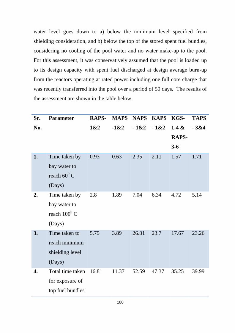
100
water level goes down to a) below the minimum level specified from
shielding consideration, and b) below the top of the stored spent fuel bundles,
considering no cooling of the pool water and no water make-up to the pool.
For this assessment, it was conservatively assumed that the pool is loaded up
to its design capacity with spent fuel discharged at design average burn-up
from the reactors operating at rated power including one full core charge that
was recently transferred into the pool over a period of 50 days. The results of
the assessment are shown in the table below.
Sr.
No.
Parameter RAPS-
1&2
MAPS
-1&2
NAPS
- 1&2
KAPS
- 1&2
KGS-
1-4 &
RAPS-
3-6
TAPS
- 3&4
1. Time taken by
bay water to
reach 600 C
(Days)
0.93 0.63 2.35 2.11 1.57 1.71
2. Time taken by
bay water to
reach 1000 C
(Days)
2.8 1.89 7.04 6.34 4.72 5.14
3. Time taken to
reach minimum
shielding level
(Days)
5.75 3.89 26.31 23.7 17.67 23.26
4. Total time taken
for exposure of
top fuel bundles
16.81 11.37 52.59 47.37 35.25 39.99

101
to air (Days)
5. Boil-off rate /
minimum
makeup
required
(Te/Hr)
1.72 2.53 2.86 2.73 2.76 4.34
The following can be observed from the table:
• The time available before the water level reaches minimum level
prescribed for shielding ranges from minimum 3.9 days (MAPS) to
maximum 26.3 days (NAPS).
• In case of MAPS-1&2 and RAPS-1&2 the emergency preparedness for
making up water should match the requirements of 3.9 and 5.75 days
respectively with sufficient safety margin.
• The time available before the top layer of fuel bundles is exposed is
16.81 days for RAPS-1&2, 11.4 days in case of MAPS-1&2 and for
other reactors it is more than one month.
• The bulk boiling of water can start within as low as 1.9 days (MAPS) to
7 days (NAPS). It should be checked whether such boiling can affect the
structural integrity of the pool.
• An external water hookup provision for maintaining the required level in
SFSB for all the operating plants should be implemented irrespective of
any other design provision. This make up capability should remain
unaffected by the impact of the external events including SBO.
• The present instrumentation for monitoring level and temperature of
water in the pools and the radiation fields inside the SFSB may not be
adequate during BDBA conditions like those experienced at Fukushima.

102
Accordingly, suitable passive monitoring/indication facilities should be
provided for these parameters.
Further work
Detailed site specific safety assessment of SFSBs should be done further
with respect to the following.
• Structural and leak tightness integrity of pools to withstand external
events
• Earthquake induced water sloshing losses
• Need and adequacy of power supply for SFSB water cooling and its
availability during external events
• Stability of fuel storage racks and mechanical handling equipment like
overhead cranes, including possibility of their falling and creating
secondary damages
C.5 Heavy water upgrading plants
Current safety status
The Heavy Water Upgrading Plant (UGP) is an auxiliary system to nuclear
power plant and its availability or operation does not have any effect on
power plant operational safety. In case of total power failure after any
external event, the Upgrading Plant will go to safe shutdown mode.
Upgrading Plant building is a single storey RCC structure. Two Distillation
columns are housed in a structural steel tower of overall size 7 m x 7 m x 58
m height. The total height of distillation column assembly is 55 meters. These
facilities are characterized with low/limited radioactivity and hence classified
as the lowest safety class and seismic category corresponding to operating
basis earthquake (OBE). An earthquake of OBE level and flooding will not
cause any significant radiological impact at the site and no impact in the

103
public domain. However, the steel tower and distillation columns would
require assessment of structural integrity for beyond design basis natural
events.
Further work
In case of external events like earthquake, tsunami, flood, cyclone of beyond
design basis level, a limited plant emergency around this facility may occur.
Further study and analysis of existing building structure and equipment,
specifically tall structural steel tower and distillation columns, need to be
carried out to assess margins available to cater to postulated level of
earthquake and impact of any failures on nearby plant facilities. This issue is
site-specific.
D. Radioactive waste management facilities at NPP sites
Near Surface Disposal Facilities (NSDF)
In India, NSDFs for disposal of solid radioactive waste generated from NPP
operation are co-located with the NPP within the exclusion boundary. These
are designed, constructed and operated based on a combination of engineered
(structure, waste matrix, backfill materials) and passive safety (geospheric
environment) features. During siting, design and construction of NSDFs, site
characteristics and external natural events, to the extent applicable, are taken
into account.
Safety assessments of NSDFs are available for all NPP sites. These
assessments are based essentially on the postulated ingress of water into the
radioactive waste disposal system and leaching of radionuclides from the
waste matrix and their subsequent migration into the groundwater. A network
of monitoring bore-holes is provided at each NSDF to assess the performance

104
of disposal system by sampling and analysis of ground water. The
radiological impact during normal conditions, as seen from these analyses, is
found to be well within the specified limits. Preliminary study indicates that
even in the case of a Fukushima type of extreme natural event, the possibility
of any significant radiological impact, especially in the public domain, is
minimal.
Spent Resin Storage Tanks
At TAPS-1&2 (and earlier at MAPS-1&2), spent ion exchange resins
generated are stored in underground tanks. The ingress of water into the
storage tanks or failure of storage tanks has the potential of spreading
contamination in the surrounding area. The radionuclide monitoring data in
bore wells around the spent resin storage facilities shows safe storage as
activity levels are below the detection limit (BDL). However, in case of any
severe event of natural origin, the integrity of these tanks may be lost that has
the potential of causing widespread radiological hazard though limited to
within the NPP premises. Removal of the resins from these tanks and
immobilization of the resins should be done at the earliest and the practice of
storage of spent resin in underground tanks should be discontinued.
Radioactive Liquid Effluent Storage and Treatment
Radioactive liquid effluents generated from PHWRs are collected in the
liquid effluent segregation and storage system (LESS) or Liquid Effluent
Management Plant (LEMP) and subsequently transferred to the treatment /
disposal facility. The liquid waste storage tank area i.e. civil structure of
LESS and the surrounding dykes are designed and constructed as per the
seismic qualification of OBE. The LESS/LEMP tanks are designed for
storage capacity equivalent to two days effluent generation from the plant.
105
The holding capacity of dyke tanks located in a multi-unit site is equivalent to
about 21 days of waste volume generation.
In the event of failure of tanks in a design basis accident, the entire volume of
water will be retained within the dyke. The management and disposal of the
water inside the dyke wall will be carried out on a campaign basis.
Assessment of the postulated consequences of beyond design basis external
events e.g. simultaneous failure of tanks and dykes requires further study.
However, even in such a case, there is no possibility of any significant impact
in the public domain due to the large distance of over 1 km between the dykes
and the exclusion boundary.
Further Work
An estimate of volume and activity of the radioactive effluents likely to be
generated during any postulated nuclear accident including any accident due
to extreme natural events needs to be made. Subsequently, a scheme for
treatment of such effluents is to be worked out. Such systems are
recommended to be modular in design which can be transported to the
affected site and pressed into service on short notice.

106
Annexure-7
RECOMMENDATIONS FOR EXTREME NATURAL EVENTS
OTHER THAN EARTHQUAKE AND TSUNAMI
(i) Extreme flood due to cyclones at coastal sites: Considering available
data on past cyclonic storms, a pressure drop of 100 millibar, associated
wind speed of 300 kmph for east coast and 240 kmph for west coast,
translational speed of 40 kmph and a radius of 50 km may be taken as
upper bound values for the postulated extreme cyclonic storm.
(ii) In case of flooding caused due to postulated dam break, a conservative
upper bound analysis (in terms of postulated size, extent and duration of
break) is recommended along with a rainfall/flood of 100 year return
period.
(iii) Considering past rainfall data at NPP sites, an extreme flood event to be
used for assessment of safety margin against flooding at NPP sites,
which would correspond to at least one order higher return period, may
be defined as follows:
Site surface drainage: 15% additional over the calculated design
basis rainfall (mean plus one standard deviation corresponding to
1000 years return period).
Inland sites extreme flood: 15% additional volume/flow of water
over the calculated probable maximum flood of 1000 year return
period.
(iv) Regulatory requirements for design basis atmospheric temperature
should be specified as (mean + one standard deviation) corresponding to

107
1000 year mean return period for high value and (mean - one standard
deviation) corresponding to 1000 year mean return period for low value.
Beyond design basis temperature values for margin assessment may be
specified as (mean + two standard deviations) corresponding to 1000
year mean return period for high value and (mean - two standard
deviations) corresponding to 1000 year mean return period for low value.
(v) An extreme wind event for safety margin assessment should correspond
to over 10000 year return period. In lieu of this, the design basis wind
speed increased by 50% and rounded off to nearest 10 m/s speed may be
considered as an extreme wind event for margin assessment.

108
Annexure-8
SAFETY ASSESSMENT OF KUDANKULAM NUCLEAR POWER
PLANT UNITS-1&2 (KK NPP1&2) IN THE WAKE OF FUKUSHIMA
ACCIDENT
Two Units of VVER Pressurized Water Reactors (Model V-412) each of
1000 MW rating are being built at the Kudankulam Site in Tamil Nadu.
Initial commissioning activities for Unit # 1 have started with AERB issuing
clearance for “Hot-Run” on June 30, 2011. Construction of Unit # 2 is in an
advanced stage of completion.
The design of KK NPP incorporates a number of engineered safety features
(ESFs) for catering to design basis accidents (DBAs) and beyond design basis
accidents (BDBAs), and several other design safety features.
ESFs for catering to DBA
• Emergency Core Cooling System (ECCS)
• Secondary circuit protection against over-pressurisation
• Emergency Gas Removal System
• Fission Products Removal and Control Systems
• Emergency Safety Boron Injection System
• Quick Boron Injection System (QBIS)
ESFs for catering to BDBA
• Passive Heat Removal System (PHRS)
• Additional system for core passive flooding
• Annulus passive filtering systems (APFS)
• System for retaining and cooling of molten core

109
Other salient design safety features
• 4 x 100% active safety system trains and 4 x 33% passive safety system
trains
• Large water inventory in I & II stage ECCS hydro-accumulators
• Automatic Reactor Scram on seismic signal
• Battery banks with 24 hrs capacity
• Sea water pumps located at more than 2.2m above design basis flood
level (DBFL).
• Safety related buildings and structures located at least 3.0m above
DBFL.
• A shore protection rubble wall
Post-Fukushima safety Assessment
A Task Force (TF) constituted by NPCIL carried out safety assessment of
KKNPP-1&2 in the light of Fukushima accident and its findings were
reviewed by the AERB’s Advisory committee on Project safety review of
light water reactors (ACPSR-LWR) and the AERB committee on safety
review of Indian NPPs in the light of Fukushima accident. Salient points
emerging from the assessment and its reviews are given below.
• Back up provisions from alternate sources should be made for
- Charging water to secondary side of SGs
- Make-up of borated water to spent fuel pools
- Injection of borated water in the reactor coolant system
• Seismic qualification of emergency water storage facility and
augmentation of its storage capacity for core decay heat removal for a
period of at least one week
• Mobile self powered pumping equipment for emergency use

110
• Facility for monitoring safety parameters using portable power packs
• Finalization of emergency operating procedures for BDBA conditions
• Primary Containment to be assessed for ultimate load bearing capacity.
• Doors and barrels of airlocks to be qualified for proof test pressure
• Ensuring that highly active water used for cooling the core catcher
vessel under BDBA is contained inside the primary containment
• Reconfirmation of design adequacy of hydrogen management system
• Environmental qualification of core catcher temperature monitoring
system
• Adequacy of design provision for remote water addition to core catcher
• Adequacy of instrumentation for monitoring plant status during BDBA
• Details of margin available on location of various safety related SSCs
above DBFL should be reviewed again.
• Need for design provision for containment venting, that has been
deleted, should be re-examined.
• The backup sources for water injection to SG secondary side should be
seismically qualified.
• Provisions for addition of water to core catcher require a detailed study,
to ensure that there is no possibility of any steam explosion.
• Provision of additional backup power supply sources for performing
essential safety functions, like air cooled DGs located at a high
elevation, should be considered.
The recommendations are being examined and NPCIL’s response would be
reviewed in ACPSR-LWR before initial fuel loading in unit-1.
111
Annexure - 9
LIST OF ABBREVIATIONS
ABDS Auto Blow Down System ABFP Auxiliary Boiler Feed Pump AC Alternating Current ACPSR Advisory Committee for Project Safety Review AERB Atomic Energy Regulatory Board AERBSC-EE AERB Committee to Review Safety of Indian NPP
against External Events in Light of Fukushima
BARC Bhabha Atomic Research Centre BDBA Beyond Design Basis Accident BDBE Beyond Design Basis Event BDL Below Detection Limit BWR Boiling Water Reactor C&I Control & Instrumentation COIS Computerised Operator Information System CRCS Control Room Computer System CRD Control Rod Drive CS&PI System Core Spray & Post Incident System DBA Design Basis Accident DBE Design Basis Event DBFL Design Basis Flood Level DBGM Design Basis Ground Motion DC Direct Current DEGB Double Ended Guillotine Break DG Diesel Generator ECCS Emergency Core Cooling System EG Expert Group EL Elevation
112
EOP Emergency Operating Procedure GSI Geological Survey of India IAEA International Atomic Energy Agency INES International Nuclear and Radiological Event Scale IP Isotopic Purity ISI In-Service Inspection JSCE Japan Society of Civil Engineers KAPS KakraparAtomic Power Station KGS Kaiga Generating Station KKNPP Kudankulam Nuclear Power Plant KVA Kilo Volt Ampere LEMP Liquid Effluent Management Plant LESS Liquid Effluent Segregation and Storage System LOCA Loss of Coolant Accident LWR Light Water Reactor MAPS Madras Atomic Power Station MRI Mean Recurrence Interval MWe Mega Watt electrical NAPS Narora Atomic Power Station NPCIL Nuclear Power Corporation of India Limited NPP Nuclear Power Plant NPSD Nuclear Projects Safety Division NSDF Near Surface Disposal Facility OBE Operating Basis Earthquake PCV Primary Containment Vessel PGA Peak Ground Acceleration PHT system Primary Heat Transport System PHWR Pressurized Heavy Water Reactor PIS Plant Information System PSA Probabilistic Safety Analysis

113
PSR Periodic Safety Review PWR Pressurized Water Reactor R&D Research & Development RAPS Rajasthan Atomic Power Station RB Reactor Building RCC Reinforced Cement Concrete RH Relative Humidity RHRS Residual Heat Removal System RPV Reactor Pressure Vessel RV Relief Valve SAMG Severe Accident Management Guidelines SBO Station Black Out SCR Supplementary Control Room SFSB Spent Fuel Storage Building SG Steam Generator SSC Structures, Systems and Components SSE Safe Shutdown Earthquake TAPS Tarapur Atomic Power Station UGP Upgrading Plant UHS Ultimate Heat Sink UPS Un-interrupted Power Supply WG Working Group