Embed Size (px)
Citation preview

ATOMIC ENERGY REGULATORY BOARD
AERB SAFETY STANDARD NO. AERB/NF/SS/CSE-4
GOVERNMENT OF INDIA
AERB SAFETY STANDARD
DESIGN, FABRICATION AND ERECTION OF EMBEDDED PARTS AND
PENETRATIONS IMPORTANT TO SAFETY OF NUCLEAR FACILITIES

AERB SAFETY STANDARD NO. AERB/NF/SS/CSE-4
DESIGN, FABRICATION AND ERECTIONOF EMBEDDED PARTS AND
PENETRATIONS IMPORTANT TOSAFETY OF NUCLEAR FACILITIES
Atomic Energy Regulatory BoardMumbai - 400 094
India
February 2003

Copyright protected information has been reproduced in this Standard, with due permission as follows,from the documents of the Canadian Standards (CSA), American Society of Mechanical Engineers(ASME), and the American Concrete Institute (ACI):
I. Design Requirements for Concrete Containment Structures for CANDU Nuclear PowerPlants, Canadian National Standard No. CAN3-N287.3-M82, 1982 Edition :
Sections/sub-sections : 15.4.2.3, 15.4.2.5, 15./4.2.7, 15.4.3.3., and Figure : 3 & 4.
With the permission of CSA International, material is reproduced from CSA Standard CAn3-N287.3-M82, Design Requirements for Concrete Containment Structures for CANDU Nuclear Power Plants,which is copyrighted by CSA International, 178 Rexdale Blvd., Etobicoke, Ontario, M9W IR3.While use of this material has been authorized, CSA International shall not be responsible for themanner in which the information is presented, nor for any interpretations thereof.
II. Rules for Construction for Nuclear Power Plant Components, American Society ofMechanical Engineers Boiler and Pressure Vessel Code, Section III, Division 1, Sub-sectionNE, 1998 Edition:
Figure : NE-1120-1
Reprinted from ASME Section III, Sub-section NE by permission of The American Society ofMechanical Engineers. All rights reserved.
III. Code Requirements for Nuclear Safety Related Concrete Structures, American ConcreteInstitute Document No. ACI 349-85 and Commentary-ACI 349-85, 1985 Edition :
Figure : B.1-1, B.1-2, B.7-1
Copyright @ The American Concrete Institute. Reprinted with permission. All rights reserved.
Price:
Orders for this Standard should be addressed to:
Administrative OfficerAtomic Energy Regulatory Board
Niyamak BhavanAnushaktinagar
Mumbai - 400 094India

FOREWORD
Activities concerning establishment and utilization of nuclear facilities and use ofradioactive sources are to be carried out in India in accordance with the provisions ofthe Atomic Energy Act 1962. In pursuance of the objective to ensure safety of membersof the public and occupational workers as well as protection of environment, the AtomicEnergy Regulatory Board has been entrusted with the responsibility of laying downsafety standards and framing rules and regulations for such activities. The Board has,therefore, undertaken a programme of developing safety standards, codes of practiceand related guides and manuals for the purpose. These documents cover aspects suchas siting, design, construction, operation, quality assurance, decommissioning andregulation of nuclear and radiation facilities.
Codes of practice and safety standards are formulated on the basis of internationallyaccepted safety criteria for design, construction and operation of specific equipment,systems, structures and components of nuclear and radiation facilities. Safety codesestablish the objectives and set minimum requirements that shall be fulfilled to provideadequate assurance for safety. Safety guides elaborate various requirements and furnishapproaches for their implementation. Safety manuals deal with specific topics andcontain detailed scientific and technical information on the subject. These documentsare prepared by experts in the relevant fields and are extensively reviewed by advisorycommittees of the Board before they are published. The documents are revised whennecessary, in the light of the experience and feedback from users as well as newdevelopments in the field.
Civil engineering structures in nuclear installations form an important feature havingimplications to safety performance of these installations. The objective and minimumrequirements for the design of civil engineering buildings/structures that shall befulfilled to provide adequate assurance for safety of nuclear installations in India arespecified in the Safety Standard for Civil Engineering Structures Important to Safetyof Nuclear Facilities (No. AERB/SS/CSE). The present standard is written to specifyguidelines for implementation of the above civil engineering safety standard in design,fabrication and erection of embedded parts and penetrations important to safety.
Consistent with the accepted practice, ‘shall’, ‘should’ and ‘may’ are used in thestandard to distinguish between a firm requirement, a recommendation and a desirableoption, respectively. Appendices are an integral part of the document, whereasannexures, footnotes, references/bibliography and lists of participants are included toprovide information that might be helpful to the user. Approaches for implementation
i

different to those set out in the Standard, may be acceptable, if they provide comparableassurance against undue risk to the health and safety of the occupational workers andthe general public and protection of the environment.
For aspects not covered in this standard, applicable and acceptable national andinternational standards, codes and guides should be followed. Non-radiological aspectsof industrial safety and environmental protection are not explicitly considered.Industrial safety is ensured through compliance with the applicable provisions of theFactories Act, 1948 as amended in 1987 and the Atomic Energy (Factories) Rules,1996.
This Standard has been prepared by specialists in the field drawn from the AtomicEnergy Regulatory Board, Bhabha Atomic Research Centre, Nuclear Power Corporationof India Limited, Development Consultants Limited, Tata Consulting Engineers andBureau of Indian Standards. It has been reviewed by the relevant AERB AdvisoryCommittee on Codes and Guides and the Advisory Committee on Nuclear Safety.
AERB wishes to thank all individuals and organisations who have prepared andreviewed the draft and helped in its finalisation. The list of persons, who haveparticipated in this task, along with their affiliations, is included for information.
(Suhas P. Sukhatme)Chairman, AERB
ii

DEFINITIONS
Acceptable Limits
Limits acceptable to Regulatory Body for accident condition or potential exposure.
Accident Conditions
Substantial deviations from Operational States which could lead to release ofunacceptable quantities of radioactive materials. They are more severe than anticipatedoperational occurrences and include Design Basis Accidents as well as beyond DesignBasis Accidents.
Anticipated Operational Occurrences
An operational process deviating from normal operation which is expected to occurduring the operating lifetime of a facility but which, in view of appropriate designprovisions, does not cause any significant damage to Items Important to Safety norlead to Accident Conditions.
Approval
A type of regulatory consent issued by the Regulatory Body to a proposal.
Atomic Energy Regulatory Board (AERB)
A national authority designated by the Government of India having the legal authorityfor issuing regulatory consent for various activities related to the nuclear and radiationfacility and to perform safety and regulatory functions including enforcement for theprotection of site personnel, the public and the environment from undue radiationhazards.
Attachment
An attachment is an element in contact with or connected to the inside or outside of acomponent. It may have either a pressure retaining or non-pressure retaining function.
Construction
The process of manufacturing, testing and assembling the components of a nuclear or
iii

radiation facility, the erection of civil works and structures, the installation of componentsand equipment and the performance of associated tests.
Design Basis Accidents (DBAs)
A set of postulated accidents which are analysed to arrive at conservative limits onpressure, temperature and other parameters which are then used to set specificationsthat must be met by plant structures, systems and components and fission productbarriers. .
Design Leak Rate (for Containment Penetration Assembly)
The maximum permissible leak rate, at design pressure and temperature, through theassembly in the event of a design basis accident inside the reactor containment.
Embedded Parts
Any structural member, plate, angle, channel, pipe sleeve or other section anchored toa concrete structure through direct bond or other anchors.
Embedment
The embedment is that portion of the component in contact with the concrete or groutused to transmit applied loads to the concrete structure through direct bond or otheranchors. The embedment may be fabricated lugs, bolts, plates, reinforcing bars, shearconnectors, expansion anchors, inserts or any combination thereof.
Examination
An element of inspection consisting of investigation of materials, components, suppliesor services to determine conformance with those specified requirements which can bedetermined by such investigation.
Expansion Fastener
A component installed in hardened concrete for the transfer of loads into the concreteby direct bearing and/or friction.
Guard Pipe
A pipe sleeve used to guard a penetration assembly.
iv

Inspection
Quality control actions which by means of examination, observation or measurementdetermine the conformance of materials, parts, components, systems, structures aswell as processes and procedures with predetermined quality requirements.
Items Important to Safety (IIS)
The items which comprise:
(1) those structures, systems, equipment and components whose malfunction orfailure could lead to undue radiological consequences at Plant site or off-site.
(2) those structures, systems, equipment and components which preventAnticipated Operational Occurrences from leading to Accident Conditions;
(3) those features which are provided to mitigate the consequences of malfunctionor failure of structures, systems, equipment or components.
Normal Operation
Operation of a plant or equipment within specified operational limits and conditions.In case of nuclear power plant this includes start-up, power operation, shutting down,shutdown state, maintenance, testing and refueling.
Nuclear Facility
All nuclear fuel cycle and associated installations encompassing the activities coveringfrom the front end to the back end of nuclear fuel cycle processes and also the associatedindustrial facilities such as; heavy water plants, beryllium extraction plants, zirconiumplant, etc.
Nuclear Power Plant A nuclear reactor or a group of reactors together with all the associated structures,systems, equipment and components necessary for safe generation of electricity.
Peak Stress
The increment of stress which is additive to the primary plus secondary stresses byreason of local discontinuities or local thermal stress including the effects, if any, of
v

stress concentrations. Its basic characteristic is that it does not cause any noticeabledistortion and is objectionable only as a possible source of a fatigue crack or brittlefracture. A stress which is not highly localised falls in this category if it is of a typewhich cannot cause noticeable distortion. Examples of peak stresses are stresses at alocal structural discontinuity, certain thermal stresses which may cause fatigue butnot distortion, surface stresses produced by thermal shock etc.
Prescribed Limits
Limits established or accepted by the Regulatory Body.
Primary Stress
Any normal stress or a shear stress developed by an imposed loading which is necessaryto satisfy the laws of equilibrium of external and internal forces and moments. Thebasic characteristic of a primary stress is that it is not self-limiting.
Quality
The totality of features and characteristics of an item or service that bear on its abilityto satisfy stated or implied needs.
Quality Assurance
Planned and systematic actions necessary to provide adequate confidence that an itemor a facility will satisfy given requirements for quality.
Quality Control
Quality Assurance actions, which provide a means to control and measure thecharacteristics of an item, process or facility in accordance with establishedrequirements.
Records
Documents which furnish objective evidence of the quality of items and activitiesaffecting quality. It also includes logging of events and other measurements.
vi

Responsible Organisation
The organisation having overall responsibility for siting, design, construction,commissioning, operation and decommissioning of a facility.
Safety
The achievement of proper operating conditions, prevention of accidents or mitigationof accident consequences, resulting in protection of site personnel, the public and theenvironment from undue radiation hazards.
Secondary Stress
Secondary stress is a normal stress or shear stress developed by the constraint ofadjacent material or by self-constraint of the structure. The basic characteristic of asecondary stress is that it is self-limiting.
Structure
The assembly of elements which supports/houses the plants, equipment and systems.
Testing (QA)
The determination or verification of the capability of an item to meet specifiedrequirements by subjecting the item to a set of physical, chemical, environmental oroperational conditions.
vii

SPECIAL DEFINITIONS(Specific to the present standard)
Design Service Conditions
The service conditions used as the basis for rating or design qualification of structures,systems, equipment or any other item.
Electric Cable Core Sealing (Power and Control Cables)
A provision made to minimise the leakage of fluids that could escape through theinterstices between the insulated cores of a cable.
Electric Cable Strand Sealing (Power Cables)
A provision made to minimise the leakage of fluids that could escape through theinterstices between the strands of the conductor of a cable.
Qualified Life
The estimated time, determined by tests (normal or accelerated) for which the embeddedparts and penetration assembly will meet all design requirements for the specifiedservice conditions.
Qualified Life Test
Tests performed on preconditioned test specimens to verify that the item will meet thedesign requirements at the end of its qualified life.
Service Conditions
All conditions expected as a result of normal operating requirements, expected extremesin operating requirements and postulated conditions appropriate for the design basisevents of the station, applicable to the penetration assembly and embedded parts.
Vendor
A design, contracting or manufacturing organisation, supplying a service, componentor plant.
viii

SYMBOLS
Symbols used in this standard shall have the following meaning, unless otherwisedefined elsewhere in this standard. The symbols defined hereunder may not necessarilyconform to the symbols adopted elsewhere for national or international use. Unlessspecified otherwise, SI units are adopted.
Ag
Gross cross-sectional area of concrete members.
A1
Full cross sectional area of concrete support.
A2
Area of bearing support; maximum area of the portion of the supportingsurface that is geometrically similar to and concentric with the loaded area;same unit as in A
1.
bw
Web width.
D Nominal diameter.
DL Dead load.
d Effective depth of flexural member, or distance from extreme compressionfibre to centroid of tension reinforcement.
Eo
Load effects due to Operating Basis Earthquake, including responses ofsupported components, piping and equipment, hydrodynamic effects anddynamic effects of surrounding soil.
Ess
Load effects due to Safe Shutdown Earthquake, including responses ofsupported components, piping and equipment, hydrodynamic effects anddynamic effects of surrounding soil.
F Loads resulting from the application of prestress.
Fh
Hydrostatic load due to internal flooding.
FF Load effects due to design basis flood.
fck
Characteristic compressive strength (in MPa) of 150 mm concrete cube at 28days.
ix

fut
Minimum specified tensile strength.
fy
Characteristics strength of reinforcing steel, corresponding to 0.2% proofstress for high strength deformed bars or yield stress in case of mild steel.
H Lateral earth pressure.
LL Live loads, including any movable equipment loads, construction and otherloads which vary with intensity and occurrence, such as soil pressure; thelive load shall be considered to vary from zero to full value for all loadcombinations.
m Minimum side cover distance.
n Number of threads per cm.
Pa
Maximum differential pressure load generated by a postulated design basisaccident.
Pd
Design pullout load of concrete.
Pt
Pressure load during the structural integrity and leak rate tests, whereapplicable.
Pv
Pressure loads resulting from pressure variation either inside or outside thecontainment.
Ro
Pipe and equipment reactions during normal operating or shutdownconditions, based on the most critical transient or steady-state condition,excluding dead load and earthquake reactions.
Ra
Pipe and equipment reactions generated by a postulated accident used as adesign basis; and including R
o.
To
Thermal effect loads during normal operation; start-up or shut-downconditions, based on the most critical transient or steady state conditions.
Ta
Thermal effect loads generated by a postulated design basis accident andincluding T
o.
x

Tt
Thermal effect loads during the test.
t Nominal plate thickness less corrosion allowance.
WC Load generated by severe wind.
Wt
Load generated by the design tornado specified for the plant; this includescombined loads due to the tornado wind pressure, tornado created differentialpressure and tornado generated missiles.
Yj
Jet impingement load on structure generated by a postulated accident usedas a design basis.
Ym
Missile impact load on structure, such as pipe whipping generated by orduring a postulated accident used as a design basis.
Yr
Loads on the structure generated by the reaction of the high energy pipebroken due to a postulated accident used as design basis.
µ Coefficient of friction between steel and concrete.
xi

CONTENTS
FOREWORD ............................................................................................... i
DEFINITIONS ............................................................................................ iii
SPECIAL DEFINITIONS ............................................................................. viii
SYMBOLS ................................................................................................... ix
1. INTRODUCTION ......................................................................... 1
1.1 General ............................................................................. 1
1.2 Safety Design Basis ........................................................... 2
1.3 Scope ................................................................................ 2
1.4 Quality Assurance............................................................... 4
1.5 Approval of Special Design and Construction
Techniques ........................................................................ 4
1.6 Structure of the Document ................................................ 4
2. EMBEDDED PARTS, PENETRATIONS AND ATTACHMENTS .. 5
2.1 General ............................................................................. 5
2.2 Embedded Parts ................................................................ 5
2.3 Penetrations ...................................................................... 6
2.4 Attachments ...................................................................... 7
2.5 Safety and Seismic Classification ...................................... 8
2.6 Materials ........................................................................... 8
3. DESIGN REQUIREMENTS ........................................................... 27
3.1 General ............................................................................. 27
3.2 Design Life Span .............................................................. 27
3.3 Methods of Design ............................................................. 27
3.4 Load ................................................................................. 28
3.5 Design of Concrete for Embedment Effects ....................... 31
3.6 Design of Steel Attachment/Embedment ............................. 42
3.7 Miscellaneous Design Aspects ........................................... 48
3.8 Corrosion Protection ......................................................... 49

4. SPECIAL REQUIREMENTS OF EMBEDDED PARTS .................. 51
4.1 General ............................................................................. 51
4.2 Expansion Anchors ........................................................... 51
5. SPECIAL REQUIREMENTS OF PENETRATION ASSEMBLIES.. 52
5.1 Electrical Penetration Assembly (EPA) ............................... 52
5.2 Mechanical Penetration Assembly ..................................... 53
5.3 Fire Resistant Design ........................................................ 54
6. FABRICATION AND INSTALLATION REQUIREMENTS OF EMBEDDEDPARTS, PENETRATION ASSEMBLIES AND
THEIR COMPONENTS ................................................................. 56
6.1 General ............................................................................ 56
6.2 Fabrication and Installation ............................................... 56
7. QUALITY ASSURANCE ............................................................... 58
7.1 General ............................................................................. 58
7.2 Verification ........................................................................ 58
7.3 Non-Conformance .............................................................. 58
7.4 Calculations ...................................................................... 59
7.5 Drawings .......................................................................... 59
7.6 Surveillance and In-service Inspection .............................. 59
7.7 Data and Documentation ................................................... 60
8. TESTING ...................................................................................... 61
8.1 General ............................................................................. 61
8.2 Anchors ............................................................................ 61
8.3 Installed Expansion Anchors, Grouted Anchors and Inserts 61
8.4 Tests on Electrical Penetration Assembly ........................... 62
8.5 Field Testing of Mechanical Penetration Assemblies ........... 63
8.6 Special Tests ..................................................................... 64

ANNEXURE I- CLASSIFICATION OF REACTOR BUILDING EPsFOR FIRE RESISTANCE ................................................. 65
BIBLIOGRAPHY ........................................................................................ 70
LIST OF PARTICIPANTS ............................................................................ 72
CODE COMMITTEE FOR CIVIL AND STRUCTURALENGINEERING (CCCSE) .......................................................................... 72
ADVISORY COMMITTEE ON NUCLEAR SAFETY (ACNS) ................... 73
LIST OF CIVIL AND STRUCTURAL ENGINEERING STANDARDS,GUIDES AND MANUALS .......................................................................... 74

1. INTRODUCTION
1.1 General
1.1.1 There is no comprehensive Indian Standard (IS) dealing with the design ofembedded parts and penetrations. The design standards of other countries,e.g., USA, Canada, France, etc., were adapted for the engineering of embeddedparts and penetrations for previous Indian Nuclear Power Plants (NPPs).One vital question that arose during the time was how to assure thecompatibility of Indian materials, used in the construction, with the designspecification of other countries’ codes. The second important point was aboutthe integration of Indian practice of design and construction with the codalrequirements of other countries. In view of this, in 1990, AERB decided toprepare its own document for the design, fabrication and erection of embeddedparts and penetrations important to safety of Indian NPPs.
The present document may be viewed as the Indian design standard for theembedded parts and penetrations important to safety of nuclear facilities. Toprepare this standard as per the scope mentioned above, CCCSE (CodeCommittee of Civil and Structural Engineering) derived assistance from thefollowing codes/standards:
(a) ACI 349-85 (1985), Code Requirements for Nuclear Safety RelatedConcrete Structures (ACI 349-85) and Commentary - ACI 349R-85, American Concrete Institute, Detroit, Michigan.
(b) ASME (1989), Component Supports, ASME Boiler and PressureVessel Code, Section III, Rules for Construction of Nuclear PowerPlant Component, Division 1 - Sub-section NF.
(c) CAN3-N287.3-M82, Design Requirements for ConcreteContainment Structures for CANDU Nuclear Power Plants, CanadianStandards Association.
(d) CAN3-N287.2-M82, Material Requirements for ConcreteContainment Structures for CANDU Nuclear Power Plants, CanadianStandards Association.
(e) IEEE (1984), IEEE Standard for Electrical Penetration Assembliesin Containment Structures for Nuclear Power Generating Stations,The Institute of Electrical and Electronics Engineers, Inc., New York.
1

(f) IEEE (1980), IEEE Standard for Installation, Inspection and TestingRequirements for Class 1E Instrumentation and Electric Equipmentof Nuclear Power Generating Stations.
1.1.2 The functional and safety requirements of the embedded parts and penetrationsimportant to safety of a Nuclear Power Plant (NPP) call for special designrequirements. The safety standard for Civil Engineering Structures Importantto Safety of Nuclear Facilities, No. AERB/SS/CSE, describes the philosophy,design approach and design requirements of buildings and structuresimportant to safety. This standard describes the criteria and methodology fordesign, fabrication, testing and erection of embedded parts, penetrations andattachments important to safety in line with the stipulations of AERB/SS/CSE.
1.2 Safety Design Basis
1.2.1 The goal of nuclear safety is to protect site personnel, the public, and theenvironment by establishing and maintaining effective safety againstradiological hazard.
1.2.2 The design of embedded parts, penetrations and attachments in NPPs shallbe based on the above safety goal. The penetration assemblies and embeddedparts in the containment shall be planned, designed, fabricated, installedand maintained such that they serve their intended functions to restrict therelease of radioactivity in the environment within prescribed limits undernormal operating condition and within acceptable limits during and followingaccident condition.
1.2.3 All structures important to safety are classified according to the requiredsafety functions to be performed by the structures satisfying the provisions ofsections 2.3 and 2.4 of safety standard No. AERB/SS/CSE. The designconditions and respective load combinations are specified on the basis oftheir classifications. The summary of classifications of civil engineeringstructures and the corresponding design conditions with load combinationsare given in Table 2.1 of AERB/SS/CSE.
1.3 Scope
1.3.1 The standard deals with methods for implementing the requirements of design,fabrication, inspection, testing and installation of embedded parts, penetrationsand attachments important to safety.
2
1.3.2 The standard covers the following aspects related to embedded parts,penetrations and attachments, which are important to safety:
(a) design requirements;
(b) special requirements;
(c) fabrication and installation requirements;
(d) quality assurance; and
(e) testing.
1.3.3 Exclusion
The standard does not cover the following, unless specified otherwise:
(a) the requirements for external circuits, systems or other elementswhich may be connected to the penetration assemblies and theembedded parts;
(b) the requirement for special penetrations like the air locks, equipmenthatch, and such other large openings;
(c) attachments which fall under the category of component support;and
(d) embedded parts which are not important to safety, such as thoserequired for supporting ladders, hand rails, lifting fixtures, edgeprotection of concrete, etc.
1.3.4 The data and relationships given in this document are only for the purposeof guidance.
1.3.5 The standard has been prepared primarily for a stationary nuclear powerplant. However, the provisions of this standard may be found useful for othernuclear facilities, failure of which may cause a radiological hazard in publicdomain.
1.3.6 Use of the Standard
The standard shall be used in conjunction with relevant AERB safety codes,standards, guides, and other applicable standards. In case of any conflict, theprovisions of this standard shall prevail upon the others.
3

1.4 Quality Assurance
Complete quality assurance programme for the design, fabrication anderection of embedded parts, penetrations and attachments important to safetyshall be developed in line with the provisions of section-9 of AERB/SS/CSEand section-7 of this standard.
1.5 Approval of Special Design and Construction Techniques
1.5.1 For novel or unproven methods of analysis, design and construction or foruse of special construction materials (not covered in this standard), priorapproval shall be obtained from AERB after ensuring comparable safety.
1.6 Structure of the Document
1.6.1 This standard comprises of eight sections. Each section is divided into anumber of sub-sections which are further subdivided into a number ofparagraphs or clauses.
1.6.2 Section-2 : Embedded parts, penetrations and attachments
Section-3 : Design requirements
Section-4 : Special requirements of embedded parts
Section-5 : Special requirements of penetration assemblies
Section-6 : Fabrication and installation requirements of embeddedparts, penetration assemblies and their components
Section-7 : Quality assurance
Section-8 : Testing
4

2. EMBEDDED PARTS, PENETRATIONS ANDATTACHMENTS
2.1 General
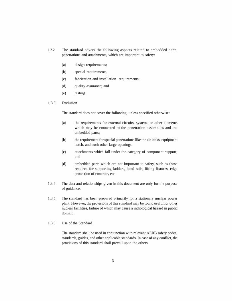
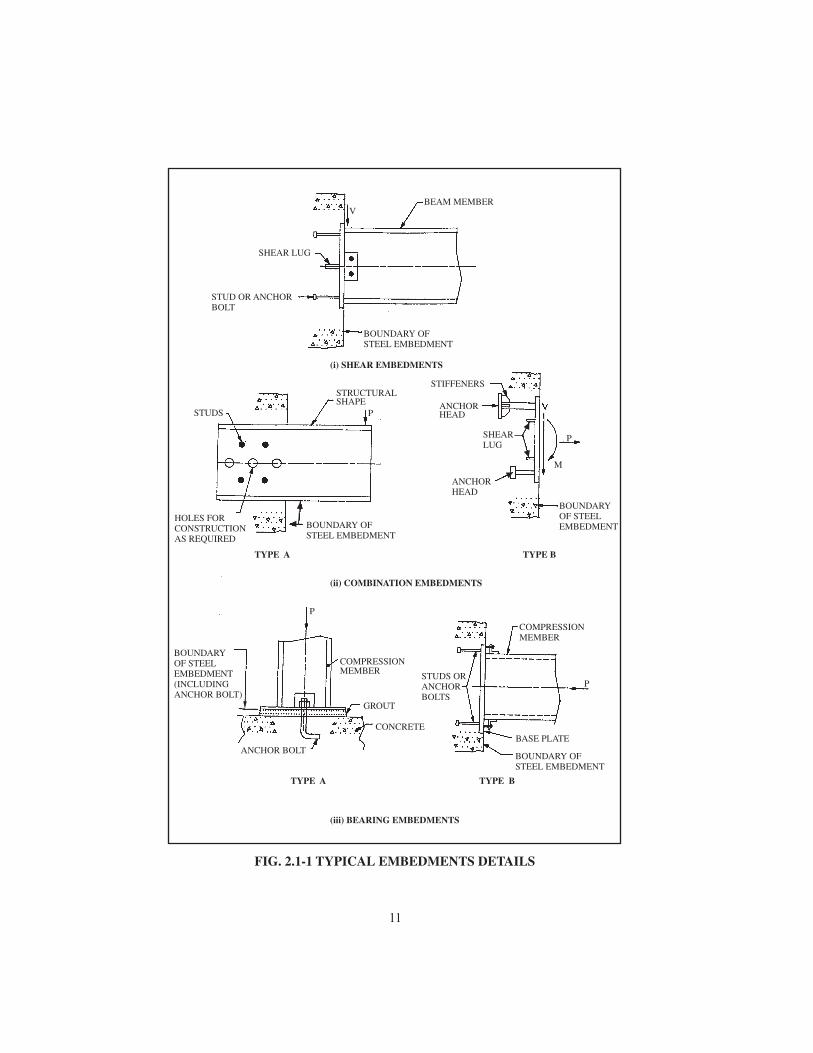
2.1.1 The general function of embedded parts and attachments is to transmit theload of the supported system to the supporting structure. Typical details ofsteel inserts, embedments and anchors are shown in Figs. 2.1-1 to 2.1-6.
2.1.2 The general function of the mechanical penetration assemblies (Figs. 2.1-7to 2.1-10) is to allow the transfer of fluids, or fuel elements into or out of thecontainment or other structures, while maintaining their integrity. Theelectrical penetration assembly (Figs. 2.1-11 to 2.1-16) provides for safepassage of one or more electrical cables through a single aperture in thecontainment structure/cell1.
2.2 Embedded Parts
The material, design, fabrication and erection of the various components ofembedded parts shall meet the basic requirements stated hereinafter.
2.2.1 Embedded Steel
The steel components partly or fully embedded in concrete, used to transmitload to the concrete structures, are considered as embedded steel.
2.2.2 Inserts
Commercially available or predesigned or prefabricated embedment installedprior to concrete placement, which are specifically designed for attachmentbolted/welded connection. A typical example of insert is given in Type A ofcombination embedments of Fig. 2.1-1.
2.2.3 Anchor Bolts
Anchor bolts, studs or bolts (Figs. 2.1-1 and 2.1-2) which transmit the partor total loads of supported system to the concrete structure.
1 Cell structures referred hereto are those of Fast Breeder Reactor (FBR) and other nuclearinstallations.
5
2.2.4 Anchor Head
A nut, washer, plate, stud or bolt head or other steel component used totransmit anchor loads to the concrete by bearing. Typical anchor heads areshown in Figs. 2.1-1 and 2.1-2.
2.2.5 Expansion Fasteners
2.2.5.1 Expansion fasteners are inserted into hardened concrete. They engage intothe surrounding concrete by lateral enlargement of the whole or part of theirembedded portion for the purpose of transmitting the pull-out and shearloads to the concrete structure by direct bearing and/or shear friction.
2.2.5.2 The expansion fasteners should not be used where alternative arrangementis available, particularly in the case of dynamic load of long duration. Instructures where the expansion anchor is to be used, it can be done bysatisfying the requirements of cl. 2.6.7.1, 8.2, 8.3 and 8.6 of this standard,except in the case of pre-stressed concrete structures where prior approvalof the designer is mandatory. When the use of expansion fasteners becomesunavoidable for long-duration vibrating loads, suitable safety factors asper recommendations of the designer shall be applied to the loads establishedby tests as per cl. 8.2, 8.3 and 8.6 to find out safe loads during use. However,the design load of the anchor should not be more than the value specifiedby the manufacturer.
2.3 Penetrations
2.3.1 Penetration assemblies are defined as parts or appurtenances required topermit piping, mechanical devices, or electrical connections to pass throughthe pressure retaining boundary of a containment, or through other structures.
2.3.2 Unless specified otherwise, the material, design, fabrication and erection ofthe various components of penetration assemblies shall meet the requirementsstated hereinafter.
2.3.3 In containment structures, penetrations should be circular in shape, as far aspossible. Where rectangular penetrations are essential, provision should bemade for effective concreting/grouting in the shadow.
6

2.3.4 Mechanical Penetration Assemblies
The penetration assemblies used for mechanical services are referred to asmechanical penetrations. The mechanical penetration assemblies (Figs. 2.1-7 to 2.1-10 allow the transfer of fluids, or fuel elements into or out of thecontainment structure, reactor building or from one area of the safety-relatedbuilding into another. The penetration assembly shall not adversely affectcontainment integrity.
2.3.4.1 The penetration assemblies and its components of metal containment structurewhich conform to sub-section NE (class MC components) of the ASME Boilerand Pressure Vessel Code, Section III, Division 1, are shown in Fig. 2.1-7.Penetration assemblies and its components of concrete structure whichconform to sub-section CC of ASME Boiler and Pressure Vessel Code, SectionIII, Division 2 are shown in Figs. 2.1-8 to 2.1-10. High standards ofengineering, design and workmanship shall prevail in all aspects ofcomponents and assemblies. Proven techniques shall be used in all stages ofdesign and fabrication. The penetration assembly, though essentially of tubularconstruction, can have different configurations. The sharp edges/corners shallbe rounded off.
2.3.5 Electrical Penetration Assembly
2.3.5.1 An electrical penetration assembly provides a means for the passage of oneor more electrical cables through an aperture in the containment wall andother pressure boundaries. The penetration assembly shall not adversely affectthe containment integrity.
2.3.5.2 Cabling, associated with instrumentation and control for the reactor, willalso pass through electrical penetration assemblies.
2.4 Attachments
2.4.1 Attachments on Steel Structures
Temporary or permanent lugs, brackets and other attachments can beconnected to steel structures, liners to support systems or equipment whilemaintaining the integrity of the structure/liner. However, external attachments
7

to liners are best avoided.2.4.1.1 Temporary or permanent brackets and attachments shall be designed to resist
the design loads without adversely affecting the structural integrity due toexcessive deformation or load.
2.4.1.2 The loading combinations for attachment shall conform to that of the steelstructure/liner to which it is attached, taking into account all the loads comingfrom the systems and/or equipment connected to the attachment.
2.4.1.3 Brackets and attachments connected to the structural steel/liner shall bedesigned and analysed using acceptable techniques.
2.5 Safety Classification and Seismic Categorisation
The embedded parts, penetrations and attachments shall have the same safetyclassification and seismic categorisation as that of their supporting structures.
2.6 Materials
2.6.1 Unless specified otherwise, the materials for embedded parts, penetrationsand attachments should be selected in accordance with the provisions givenhereinafter.
2.6.2 Welding and brazing material used in the manufacture of items should complywith an SFA specification in part C of the ASME Boiler and Pressure VesselCode, Section II. Appropriate provision shall be made to prevent excessiveheating of the surrounding concrete when the penetration assembly is weldedto the embedded part. These requirements need not apply to hard surfacingor a corrosion-resistant weld metal overlays not exceeding 10 percent of thebase metal thickness.
2.6.3 Embedded Parts and Attachments
Unless otherwise specified, materials of construction should conform to theprovisions of standard on Design, Fabrication and Erection of Steel StructuresImportant to Safety of Nuclear Facilities, No. AERB/SS/CSE-2, and guideon Materials of Construction for Civil Engineering Structures Important toSafety of Nuclear Facilities, No. AERB/SG/CSE-4, or equivalent. Formaterials of embedded parts and attachment in concrete containmentstructures, requirements of ASME Boiler and Pressure Vessel Code, Section
8

III, Division 2 should be satisfied.2.6.4 Penetration Assembly
Materials for all penetration assemblies in containment should be inaccordance with the requirements of ASME Boiler and Pressure Vessel Code,Section III, Division 1, sub-section NE, and Division 2, sub-section CC and/or AERB/SS/CSE-2 as applicable.
2.6.4.1 Piping
The piping material used in the fabrication of penetration assemblies shouldconform to the following specifications or their equivalents.
(a) carbon steel pipe:
(i) up to 150 mm NPS2 - IS 1239-1978/ASME SA 106 seamless;
(ii) greater than 150 mm NPS - IS 3589-1978/ASME SA 134.
The welded pipes should be fabricated from IS 2062 (grade b or c)/2002 plate with fusion welding process.
If IS 3589 pipes are used as pressure ( 0.035MPa) retainingcomponent, the welds shall be D.P./M.P. tested on root and final passesand shall be 10 percent spot radiographed. Alternatively, the weldcan be subjected to 100 percent radiography. The material propertiesof the plates which act as pressure barrier (for design pressure( 00.035MPa) shall satisfy the requirements of ASME, Section III,Division 2, CC-3000.
(b) stainless steel pipe:
(i) up to 300 mm NPS - ASME SA 376/SA 312;
(ii) greater than 300 mm NPS - ASME SA 358.
2.6.5 Bellows
All elements of the bellows should be hydraulic or expansion formed from acorrosion resistant material such as austenitic stainless steel. The startingcylinder used in the manufacture of bellows shall have minimum practical
2 NPS - Nominal Pipe Size
9
IV
IV

number of longitudinal joints. No circumferential seam welds shall be locatedon bellow to form the corrugations. The cylinder shall not be corrugated untilall welds are found to be acceptable.
2.6.5.1 The material for bellows shall conform to the requirements of ASTM A 240,Type 304L, 316, 321, inconel or equivalent.
2.6.5.2 The weld ends of the bellows shall be made either of the same base materialas that of the containment penetration nozzle and/or sleeve associated withthe structure to satisfy welding requirements or of a material that conformsto the requirements of the ASME Boiler and Pressure Vessel Code, and thatis compatible to both the expansion bellows and the nozzle and/or sleeve.
2.6.6 Cooling Coil
Tubular coils embedded in concrete for cooling shall be made from a suitablecompatible material with adequate corrosion allowance. Grades of steel likeSS-304L, 316L, SA 106 and 15-Mo-3 are some of the acceptable materials.
2.6.7 Embedded Parts (EPs), Anchor Bolts
2.6.7.1 Material used for anchor bolts, collars, load-bearing closure plates, test-closureassemblies and temporary test channels shall be compatible to each other soas to minimise any need for dissimilar weldments in the field. In general,such materials should conform to the following standards:
(a) Plates, anchor bolts and rolled sections: IS 2062: ‘Steel for GeneralStructural Purpose’. For female concrete inserts, H.Y.S.D. barsconforming to IS 1786 can also be used.
(b) Plates and anchor bolts: IS 961: ‘Specification for Structural Steel(High Tensile)’.
(c) Test channels/temporary structurals used in testing: IS 1977:‘Specification for Structural Steel (Ordinary Quality)’.
2.6.7.2 When EPs form part of the stainless steel piping where a part of the systempiping is embedded, such as active water floor drain, large and small LOCA
10


3. DESIGN REQUIREMENTS
3.1 General
(a) The provisions given hereinafter provide minimum requirementsfor design of embedded parts, penetration and attachment.
(b) The penetrations and embedded parts shall be installed in such amanner that they do not provide any significant path for leakage orradiation streaming.
(c) On walls, floors or other structures, which are to provide radiationshielding, penetration assemblies shall be so configured and placedthat shielding requirements are fully satisfied.
(d) Tests and inspections of penetrations, embedments and anchors shallbe done according to the provisions of section 8 of this standard.
(e) The limitations on leakages at the location of penetrations, inserts,embedments and anchors on concrete containment wall shall conformto the provisions of the standard on Design of Nuclear Power PlantContainment Structures, No. AERB/SS/CSE-3.
3.2 Design Life Span
Embedded parts, penetration assemblies and attachments should normallybe designed for a period which spans the plant life.
3.3 Methods of Design
3.3.1 High standards of engineering and design shall prevail in all aspects ofcomponents and assemblies. Limit state and allowable stress design methodsare acceptable unless otherwise specified. The embedment shall be designedto withstand safely all loads likely to act on it throughout its life for thefollowing design conditions:
(a) Normal design conditions which include the load combinations LC1and LC2, i.e. Normal and Severe Environmental Load Combinationsrespectively.
(b) Abnormal design conditions which include load combinations LC3,LC4, LC5 and LC6, i.e., extreme environmental, abnormal,
27

piping, etc., the system piping specifications shall govern the EPs as well.abnormal-severe environmental, and abnormal extreme environ-mental load combinations
respectively.
3.3.2 The following methods of design for the penetration assemblies, attachments,inserts, embedded parts and their components are permissible.
3.3.2.1 Design by Analysis
Design by accepted method of analysis is permissible. Proven techniques ofmodelling wherever necessary, shall be used at all stages. All stresses/strainsand deformations shall be within the allowable limits.
Anchorage system shall be designed to have a ductile failure of embeddedsteel prior to failure of the concrete. Full load transfer from anchor to concreteshall be accomplished by an anchor head or a reinforcing bar with appropriatedevelopment length.
3.3.2.2 Design by Test
If the design is based on test, the test shall be conducted to verify that thepenetration assemblies, embedded parts, attachments and inserts haveadequate strength to bear all applicable test loads. The applicable test loadsshall include safety margins.
3.3.2.3 Design by Manufacturer’s Catalogue
When the design is based on the manufacturer’s catalogues, care shall betaken in the selection of appropriate margins while converting the staticfailure loads to failure loads under static and dynamic load conditions.
3.4 Load
3.4.1 (a) Embedded parts, penetrations and attachments should be designedto have design strengths (determined according to the limit state ofstrength) at all sections at least equal to the required strengthscalculated for the factored loads and forces as stipulated in cl. 3.4.3through cl. 3.4.8 and as combined in accordance with the provisionsspecified in cl. 3.5.2.3.
(b) The loading combinations for embedment design shall conform tothat/those of the structure to which the embedment is attached, takinginto account all the loads coming from the system attached to the
28

embedment part, penetration and attachment.3.4.2 The safety margin shall not be less than that adopted in design by analysis. In
the design, consideration should be given to the effects created by theapplication of loads and their interaction with the structure. Response of thestructure to vibration, impact, differential settlement, creep, shrinkage,thermal expansion, and any type of transients should also be considered.
3.4.3 Normal Loads
DL - dead load,
H - lateral earth pressure,
LL - live load,
Pv
- pressure loads resulting during normal operating condition,
Pt
- pressure load during structural integrity and leak rate tests, whereapplicable
Tt
- thermal effect loads during test,
Ro
- pipe and equipment reactions during normal operating or shutdownconditions,
To
- thermal effect loads during normal operating, start-up or shutdownconditions,
F - loads resulting from the application of prestress.
3.4.4 The dynamic effects of live load should be considered in the analysis. Incase where a detailed dynamic analysis is performed for the crane systems,elevators, or other moving machinery, the resulting load with dynamicamplification should be used. If such an analysis is not performed, thefollowing increases over the static effects should be used to account for thedynamic effects.
- for supports of elevators - 100 %
- for cab operated travelling crane,support girders and their connectionss - 25 %
- for pendant operated travelling cranesupport girders and their connection - 10 %
- for supports of light machinery, shaft or
29

motor driven equipment - not less than 20 %- for supports of reciprocating machinery or
power-driven unit - not less than 50 %
- for hanger supports - 33 %
3.4.5 Crane Runway Horizontal Forces
In addition to the above, the horizontal forces on the crane runway should beconsidered in the live load LL. Lateral forces on the crane runways due tothe effects of moving crane trolleys should, if not otherwise specified, be 20percent of the sum of the weights of the lifted load and that of the cranetrolley, but exclusive of other parts of the crane. The longitudinal forcesshould, if not otherwise specified, be taken as 10 percent of the maximumwheel loads of the crane applied at the top of the rail.
3.4.6 Severe Environmental Loads
Eo
- load generated by operating basis earthquake,
WC - load generated by severe wind,
FF - load resulting from design basis flood.
3.4.7 Extreme Environmental Loads
Ess
- load generated by safe shutdown earthquake,
Wt
- the wind-induced load including missile generated due to extremewind.
3.4.8 Abnormal/Accidental Loads
Fh
- hydrostatic load due to internal flooding,
MA - load and other effects of aircraft impact,
ME - load of missiles due to external events other than those related towind or tornado, explosions in transportation systems, disintegrationof turbine and other components,
MI - loading due to internal missiles,
MT - loading due to missiles, wind and over pressure generated from
30

explosions in transportation systems, on land, water or in air,M
t- loading effect of turbine missile,
Pa
- maximum differential pressure load generated by postulated designbasis accident,
Ra
- pipe and equipment reactions generated due to design basis accident,
Ta
- thermal loads generated due to design basis accident,
Yj
- jet impingment load,
Ym
- impact load such as pipe whipping,
Yr
- reaction due to the broken high-energy pipe.
3.5 Design of Concrete for Embedment Effects
3.5.1 Both limit state and allowable stress design methods are acceptable in thedesign of concrete. The provision of AERB/SS/CSE-1 shall be adoptedwherever no guidelines are given hereinafter on the subject matter.
3.5.2 Limit State Method of Design
3.5.2.1 Akin to the Limit State Design of Non-Prestressed Reinforced ConcreteStructures in section-3 of AERB/SS/CSE-1, the design shall satisfy therequirement of limit state by complying with the following criteria.
Fsd £ R
sd(3.5-1)
where,
Fsd
= Design value of structural response for a particular failure mode of agiven limit state (ref. cl 3.1.3 through 3.1.10 of AERB/SS/CSE-1).
Rsd
= Design value of resistance of the member or the structure againstthe failure mode of the given limit state considered in the design orthe limiting value of design state which is under consideration.
3.5.2.2 Design value of structural response for the i th load combination shall becalculated using the following expression.
31
Fsdi
= Fs(F
di) (3.5-2)
where,
Fs(F
di) = Structural response determined by structural response analysis
for i th load combination, Fdi
Fdi
= yi S g
fij F
ij(3.5-3)
yi
= Load combination factor
gfij
= Partial safety factor of load (load factor) for j th individualload in i th load combination
Fij
= j th characteristic load for i th load combination
3.5.2.3 Load Combinations and Partial Factor of Safety for Loads (Load Factors) forLimit State of Strength
(a) Unless specified otherwise, load combinations (ref. equation 3.5-3)given in Table 3.1 shall be used.
(b) Load combination No. 18 of LC6 is applicable for reactor buildingonly.
(c) For safety class-3 and design class DC3 structures which do notperform the safety functions associated with supporting theemergency core cooling systems and other systems related to safeshutdown of reactor or to prevent/mitigate the consequences ofaccident which could result in potential off-site exposure: applicableload combinations do not include LC3 and LC6.
(d) For safety class-4 structures applicable load combinations are LC1and LC2. The value of load combination factor ψ
i for load
combination numbers 7 to 9 for load combination type LC2 is 0.75.
(e) The structural response should be evaluated, both for short term andlong term (considering the creep effect in case of concrete), for allapplicable load combinations.
(f) The effect due to the shrinkage and heat of hydration in concretecould be considered as per DL. When these effects are taken in loadcombinations Nos. 1,3,7 the load combination factor Ψ
i may be taken
as 0.75 to obtain design value.
(g) Wherever applicable, impact effect of moving load should be included
32

in the live load.3.5.2.4 Unless specified otherwise, design value of strength for a given limit state of
strength shall be calculated from the following:
Rsd
= Rs(R
d) (3.5-4)
where,
Rs (R
d) = Computed resistance of member cross-section which is deter-
mined from Rd
and1g
m
gm
= Partial factor of safety for materials given in Table 3.2
R(fk) = Expression of respective material strength under consideration
and is expressed in terms of fk which are given in Table 3.3
fk
= Characteristic strength of materials
Values of gm which are given in Table 3.2 shall be applied to relevant material
strength denoted by R(fk) given in Table 3.3.
The design pull-out strength of concrete, pd , for any embedement shall be
based on uniform tensile stress R(fk) acting on an effective stress area which
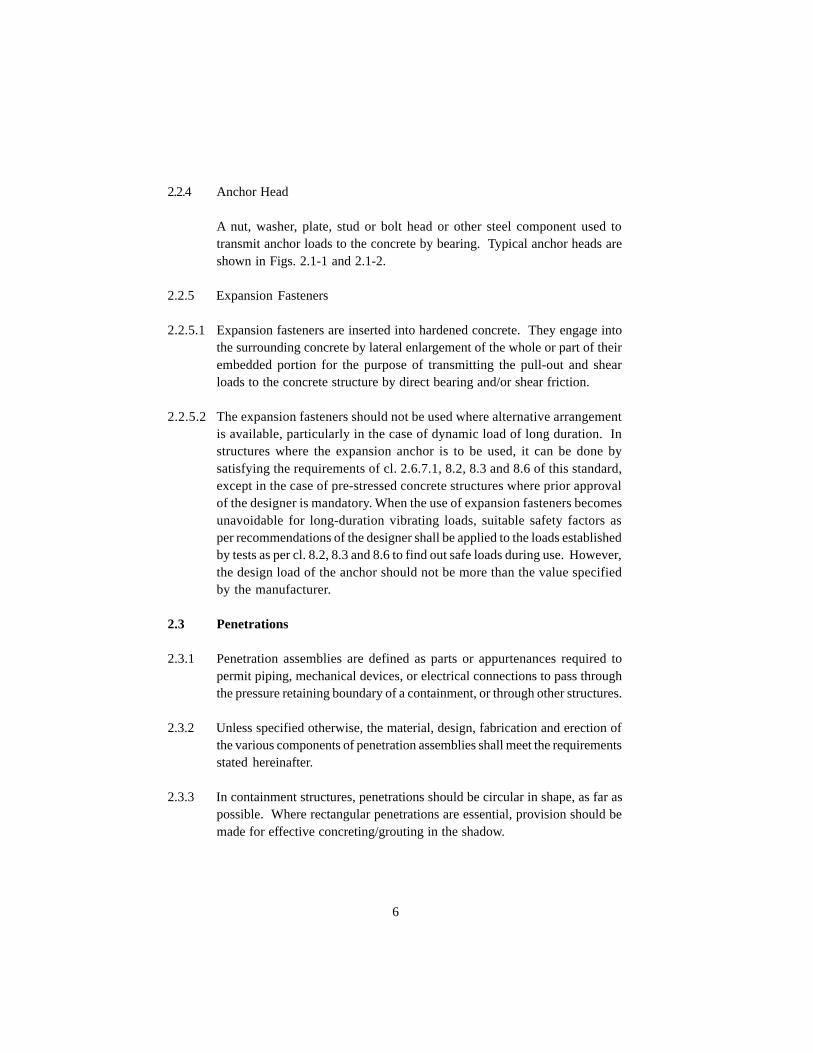
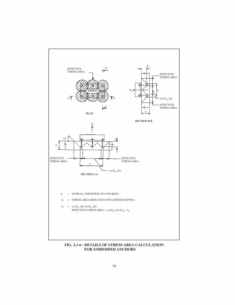
is defined by the projected area of the stress cones and limited by overlappingstress cones, by the intersection of the cones with the concrete surfaces, bythe bearing area of anchor heads, and by the overall thickness of the concrete(see Figs. 2.1-5 and 2.1-6).
3.5.2.5 Limit State of Serviceability
(a) Unless otherwise stated, following limit states of serviceability shouldbe considered:
- Deflection
- Cracking
(b) Unless specified otherwise, the value of f in equation (3.5-1) shallbe taken as unity (1.0).
Rd
= R(fk)
33
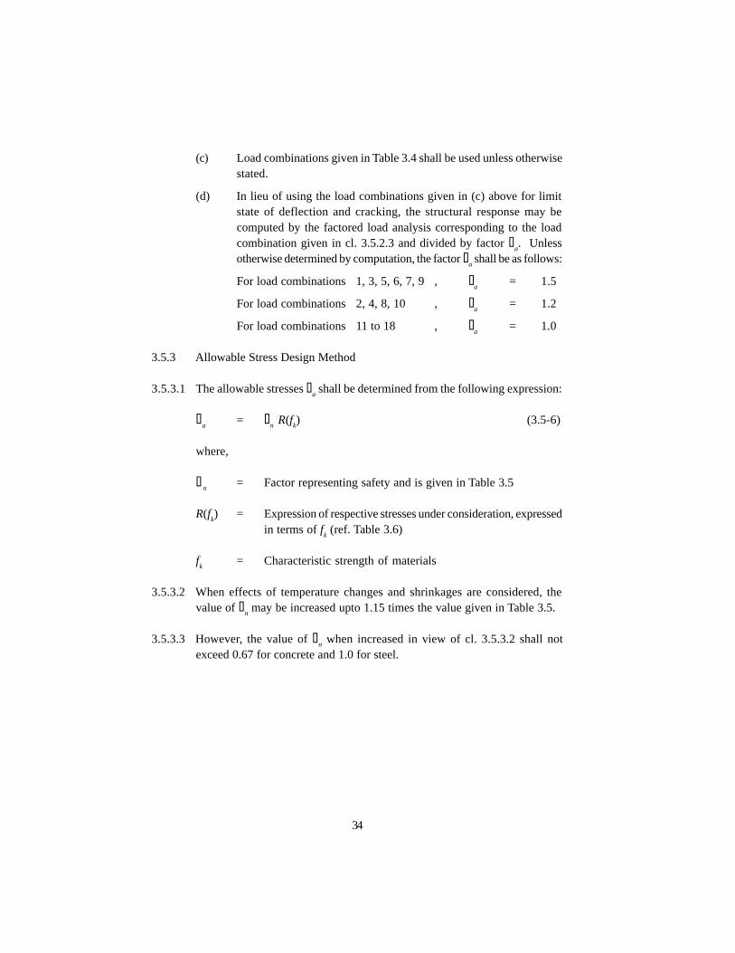
(c) Load combinations given in Table 3.4 shall be used unless otherwisestated.
(d) In lieu of using the load combinations given in (c) above for limitstate of deflection and cracking, the structural response may becomputed by the factored load analysis corresponding to the loadcombination given in cl. 3.5.2.3 and divided by factor g
a. Unless
otherwise determined by computation, the factor ga shall be as follows:
For load combinations 1, 3, 5, 6, 7, 9 , ga
= 1.5
For load combinations 2, 4, 8, 10 , ga
= 1.2
For load combinations 11 to 18 , ga
= 1.0
3.5.3 Allowable Stress Design Method
3.5.3.1 The allowable stresses sa shall be determined from the following expression:
sa
= fn R(f
k) (3.5-6)
where,
fn
= Factor representing safety and is given in Table 3.5
R(fk) = Expression of respective stresses under consideration, expressed
in terms of fk (ref. Table 3.6)
fk
= Characteristic strength of materials
3.5.3.2 When effects of temperature changes and shrinkages are considered, thevalue of f
n may be increased upto 1.15 times the value given in Table 3.5.
3.5.3.3 However, the value of fn when increased in view of cl. 3.5.3.2 shall not
exceed 0.67 for concrete and 1.0 for steel.
34

TABLE 3.1 : LOAD COMBINATIONS FOR LIMIT STATE OF STRENGTH
Load Factors γfij
35
Designcondition andloadcombinationtype
Loadcombi-na-t ionNo.
DL H (1) H (2) Ra
To
Pt
Pv
Eo or E
ss or P
aR
aT
aY
jY
mY
rMA/ME F
h
WC/ Wt
MI/MT
FF or Mt
Normal Design Condition
LC1: Normal 1 1.0 1.4 1.6 1.6 1.6 - - - - - - - - - - - - -
Load 2 0.75 1.4 1.6 1.6 1.6 1.4 - - - - - - - - - - - -
Comb. 3 1.0 1.4 1.6 1.6 1.6 - - 1.6 - - - - - - - - - -
4 0.75 1.4 1.6 1.6 1.6 1.4 - 1.6 - - - - - - - - - -
5 1.0 1.4 1.6 1.6 - - 1.6 - - - - - - - - - - -
LC2: Severe 6 1.0 0.9 - - - - - - 1.6 - - - - - - - - -
Env. Load 7 1.0 1.4 1.6 1.6 1.6 - - - 1.6 - - - - - - - - -
Comb. 8 0.75 1.4 1.6 1.6 1.6 1.4 - - 1.6 - - - - - - - - -
9 1.0 1.4 1.6 1.6 1.6 - - 1.6 1.6 - - - - - - - - -
10 0.75 1.4 1.6 1.6 1.6 1.4 - 1.6 1.6 - - - - - - - - -
Abnormal Design Condition
LC3: Extreme 11 1.0 0.9 - - - - - - - 1.0 - - - - - - - -
Env. Load 12 1.0 1.0 1.0 1.0 1.0 - - - - 1.0 - - - - - - - -
Comb. 13 1.0 1.0 1.0 1.0 1.0 1.0 - - - 1.0 - - - - - - - -
Loadcombi-nationfact-or ΨΨΨΨΨi

TABLE 3.1 : LOAD COMBINATIONS FOR LIMIT STATE OF STRENGTH (contd.)
Load Factors γfij
36
Designcondition andloadcombinationtype
Loadcombi-na-t ionNo.
Loadcombi-nationfact-or ΨΨΨΨΨi
DL H (1) H (2) Ra
To
Pt
Pv
Eo or E
ss or P
aR
aT
aY
jY
mY
rMA/ME F
h
WC/ Wt
MI/MT
FF or Mt
LC4: Abnormal 14 1.0 1.0 1.0 - - - - - - - 1.25 1.0 1.0 - - - - 1.0load 15 1.0 1.0 1.0 1.0 1.0 1.0 - 1.0 - - - - - - - - 1.0 -
comb.
LC5: Abnormal 16 1.0 1.0 1.0 - - - - - 1.15 - 1.15 1.0 1.0 1.0 1.0 1.0 - -
Severe 17 1.0 1.0 1.0 1.0 1.0 1.0 - 1.0 1.0 - 1.0 - - - - - 1.0 -
Env. Load
Comb.
LC6: Abnormal 18 1.0 1.0 1.0 1.0 - - - - - 1.0 1.0 1.0 1.0 1.0 1.0 1.0 - -
Extreme
Env. Load
Comb.
Note: (1) All load combinations shall be checked for full and zero live load condition.
(2) Effect of lateral earth pressure shall be considered in design when it is critical.

TABLE 3.2 : PARTIAL FACTOR OF SAFETY FOR MATERIALS FOR LIMIT STATE OF STRENGTH
Design Conditiong
m
Concrete Steel (g c) (g s)
Normal 1.5 1.15
Abnormal 1.3 1.0
TABLE 3.3 : EXPRESSIONS OF R(fk) FOR LIMIT STATE OF STRENGTH
Material Limit States R(fk)
(MPa)
Concrete Direct compression 0.6 fck
Flexure compression 0.67 fck
Direct Tension 0.35(fck)1/2
Flexure Tension 0.55(fck) 1/2
Pullout Tension 0.35(fck) 1/2
(ref. notes (1), (2))0.3(f
ck)1/2
(ref. note (3))
Shear Ref. Cl. 3.6.2 ofAERB/SS/CSE-1
Bond4 : Deformed bars in 0.45(fck)1/2
tension
Bond4 : Plain bars in tension 0.28(fck) 1/2
Reinforcing steel All limit states fy
Notes:(1) Embedment anchored beyond the far face reinforcement of member.(2) Embedments anchored in a compression zone of a member, or embedments anchored in a tension zone of a
member where the concrete tension stress (based on an uncracked section) at the concrete surface is less than0.30(f
ck)1/2.
(3) Cases not covered by (1) and (2) above.(4) For bars in compression, these values should be increased by 25%.
(5) fck is in MPa.
37

TABLE 3.4 : LOAD COMBINATIONS FOR LIMIT STATE OF SERVICEABILITY
Load Factors γfij
38
Design condi-t ionand load combi-nation type
Loadcombin-tion No. DL H (1) H (2) R
aT
oP
tP
vE
o or E
ss or P
aR
aT
aY
jY
mY
rMA/ME F
h
WC/ Wt
MI/MT
FF or Mt
LC1: Normal 1 1.0 1.0 1.0 1.0 1.0 - 1.0 - - - - - - - - - -
Load 2 1.0 1.0 1.0 - - 1.0 - - - - - - - - - - -
Comb.
LC2: Severe 3 1.0 1.0 1.0 1.0 1.0 - 1.0 1.0 - - - - - - - - -
Env. Load
Comb.
LC3: Extreme 4 1.0 1.0 1.0 1.0 1.0 - - - 1.0 - - - - - - - -
Env. Load
Comb.

TABLE 3.4 : LOAD COMBINATIONS FOR LIMIT STATE OF SERVICEABILITY (contd.)
Load Factors γfij
39
Design condi-t ionand load combi-nation type
Loadcombi-nationNo.
DL H (1) H (2) Ra
To
Pt
Pv
Eo or E
ss or P
aR
aT
aY
jY
mY
rMA/ME F
h
WC/ Wt
MI/MT
FF or Mt
LC4: Abnormal 5 1.0 1.0 1.0 - - - - - - 1.0 1.0 1.0 - - - - 1.0
Load 6 1.0 1.0 1.0 1.0 1.0 - 1.0 - - - - - - - - 1.0 -
Comb.
LC5: Abnormal 7 1.0 1.0 1.0 - - - - 1.0 - 1.0 1.0 1.0 - - - - -
Severe
Env. Load
Comb.
LC6: Abnormal 8 1.0 1.0 1.0 - - - - - 1.0 1.0 1.0 1.0 1.0 1.0 1.0 - -
Extreme
Env. Load
Comb.
Note: (1) All load combinations shall be checked for full and zero live load condition.
(2) Effect of lateral earth pressure shall be considered in design when it is critical.

TABLE 3.5 : VALUES OF fn FOR ALLOWABLE STRESS DESIGN
METHOD
Concrete Reinforcing steel
Normal Compression Direct 0.25 0.45
Bending 0.33 0.55
Tension Direct 0.30 0.55
Bending 0.50 0.55
Pullout 0.301,2 0.55
0.253 0.55
Shear 0.40 0.55
Bond4 Plain bars 0.25 —
Deformed bars 0.35 —
Bearing 0.30 —
Abnormal Compression Direct 0.50 0.75
Bending 0.60 0.87
Tension Direct 0.50 0.87
Bending 0.67 0.87
Pullout 0.501,2 0.87
0.403 0.87
Shear 0.50 0.87
Bond4 Plain bars 0.50 —
Deformed bars 0.67 —
Bearing 0.67 —
Notes: For (1), (2), (3) refer Table 3.3
(4) For bars in compression, increase fn by 25%.
40
fnDesign
conditionStress parameters

TABLE 3.6 : R(fk) FOR DIFFERENT STRESS PARAMETERS IN
ALLOWABLE STRESS DESIGN METHOD
Material Stress parameters R(fk)
(MPa)
Concrete Compression fck
Tension 0.7(fck)1/2
Shear1 0.18d (fck)1/2
Bond 0.7 (fck)1/2
BearingWhole area f
ck
Local area2 a fck
Reinforcing steel For all stress parameters fy
Notes:(1) d = 1, when there is no axial force
d = 1-(P/Pr), when member is subjected to axial tensile force of P;
where Pr = 0.2 (f
ck)1/2 b
wd
d = 1+(5P/Ag
fck) £ 1.5, when member is subjected to axial
compressive force of P
A1
A2
A1
= supporting area for bearing which in sloped or stepped footingmay be taken as the area of the lower base of the largest frus-tum of a pyramid or cone contained wholly within the footing,and having for its upper base, the area actually loaded andhaving side slope of one vertical to two horizontal
A2
= loaded area at the column base
(3) fck is in MPa.
(2) a = £ 2.0
12
41
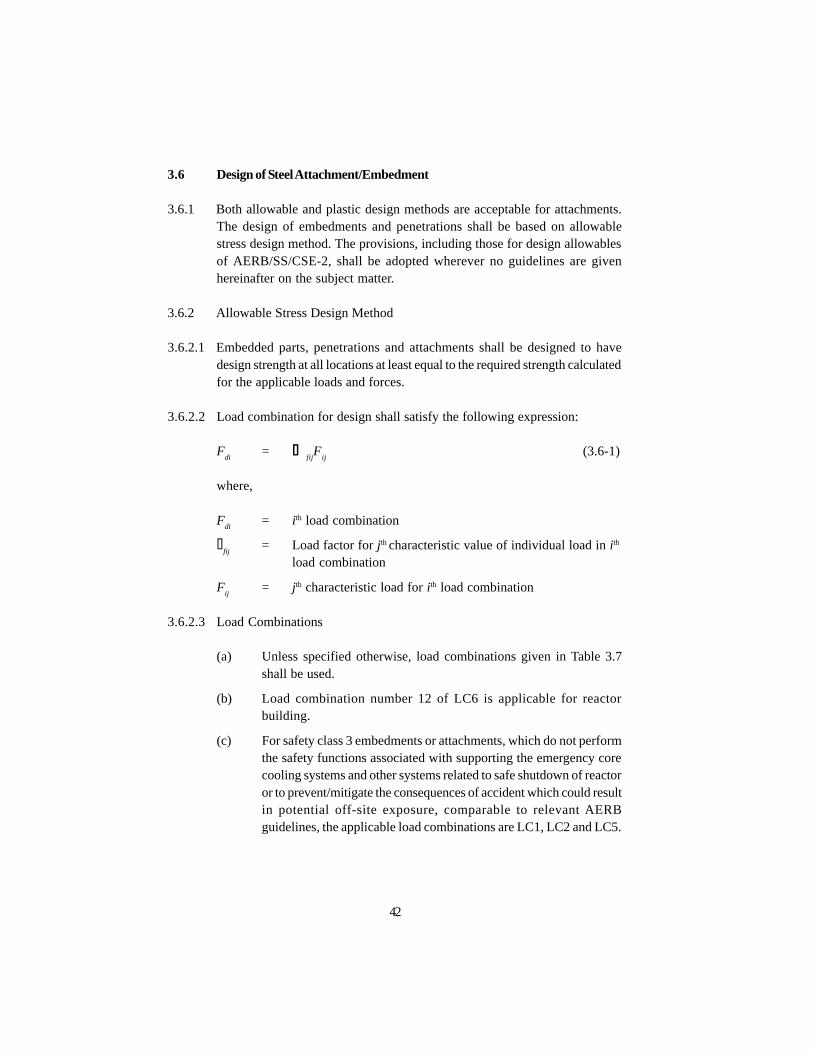
3.6 Design of Steel Attachment/Embedment
3.6.1 Both allowable and plastic design methods are acceptable for attachments.The design of embedments and penetrations shall be based on allowablestress design method. The provisions, including those for design allowablesof AERB/SS/CSE-2, shall be adopted wherever no guidelines are givenhereinafter on the subject matter.
3.6.2 Allowable Stress Design Method
3.6.2.1 Embedded parts, penetrations and attachments shall be designed to havedesign strength at all locations at least equal to the required strength calculatedfor the applicable loads and forces.
3.6.2.2 Load combination for design shall satisfy the following expression:
Fdi
= S gfijF
ij(3.6-1)
where,
Fdi
= i th load combination
gfij
= Load factor for j th characteristic value of individual load in i th
load combination
Fij
= j th characteristic load for i th load combination
3.6.2.3 Load Combinations
(a) Unless specified otherwise, load combinations given in Table 3.7shall be used.
(b) Load combination number 12 of LC6 is applicable for reactorbuilding.
(c) For safety class 3 embedments or attachments, which do not performthe safety functions associated with supporting the emergency corecooling systems and other systems related to safe shutdown of reactoror to prevent/mitigate the consequences of accident which could resultin potential off-site exposure, comparable to relevant AERBguidelines, the applicable load combinations are LC1, LC2 and LC5.
42

(d) Effects of shrinkage and creep of surrounding concrete on embedmentsshall be considered with dead load.
3.6.2.4 The design strength of steel should be in accordance with the requirementsgiven in AERB/SS/CSE-2.
3.6.3 Plastic Design Method
3.6.3.1 Attachment subjected to heavy impact and fatigue over 20,000 cycles shallnot be designed on the basis of plastic design method. Load combinationsfor plastic design shall satisfy the equation (3.6-1).
3.6.3.2 Unless specified otherwise, load combinations given in Table 3.8 shall beused.
(a) Load combination number 14 of LC6 is applicable for reactorbuilding.
(b) For safety class 3 attachments, which do not perform the safetyfunctions as specified in cl. 3.6.2.3 (c), the applicable loadcombinations are LC1, LC2 and LC5.
(c) In the above load combination, wherever applicable, impact effectof moving load is included in live load.
3.6.3.3 The design shall be made in accordance with AERB/SS/CSE-2 for plasticdesign method.
3.7 Miscellaneous Design Aspects
3.7.1 Shear-Friction
The shear-friction provisions shall be as given in AERB Safety Standard,Design of Concrete Structures Important to Safety of Nuclear Facilities,AERB/SS/CSE-1. The design yield strength f
y shall not exceed 425 N/sq.mm.
The coefficient of friction µ shall be as follows:
(a) 0.9 for concrete or grout against as-rolled steel, with the contactplane a full plate thickness below the concrete surface.
(b) 0.7 for concrete or grout against as-rolled steel, with contact planecoincidental with the concrete surface.
43

Load Factors γfij
44
Design condi-t ionand load combi-nation type
Loadcombina-tion No.
TABLE 3.7 : LOAD COMBINATIONS FOR DESIGN OF STEEL STRUCTURES
DL H (1) H (2) Ra
To
Pt
Pv
Eo or E
ss or P
aR
aT
aY
jY
mY
rMA/ME F
h
WC/ Wt
MI/MT
FF or Mt
Normal Design Condition
LC1: Normal 1 1.0 1.0 1.0 - - - - - - - - - - - - - -
Load 2 1.0 1.0 1.0 1.0 - - - - - - - - - - - - -
Comb. 3 1.0 1.0 1.0 1.0 1.0 - - - - - - - - - - - -
LC2: Severe 4 1.0 1.0 1.0 - - - - 1.0 - - - - - - - - -
Env. Load 5 1.0 1.0 1.0 1.0 - - - 1.0 - - - - - - - - -
Comb. 6 1.0 1.0 1.0 1.0 1.0 - - 1.0 - - - - - - - - -
Abnormal Design Condition
LC3: Extreme 7 1.0 1.0 1.0 - - - - - 1.0 - - - - - - - -
Env. Load 8 1.0 1.0 1.0 1.0 - - - - 1.0 - - - - - - - -
Comb. 9 1.0 1.0 1.0 1.0 1.0 - - - 1.0 - - - - - - - -

Load Factors γfij
45
Design condi-t ionand load combi-nation type
Loadcombina-tion No.
TABLE 3.7 : LOAD COMBINATIONS FOR DESIGN OF STEEL STRUCTURES (contd.)
DL H (1) H (2) Ra
To
Pt
Pv
Eo or E
ss or P
aR
aT
aY
jY
mY
rMA/ME F
h
WC/ Wt
MI/MT
FF or Mt
LC4: Abnormal 10 1.0 1.0 1.0 - - - - - - - 1.0 1.0 1.0 - - - -load
comb.
LC5: Abnormal 11 1.0 1.0 1.0 - - - - 1.0 - 1.0 1.0 1.0 1.0 1.0 1.0 - -
Severe
Env. Load
Comb.
LC6: Abnormal 12 1.0 1.0 1.0 - - - - - 1.0 1.0 1.0 1.0 1.0 1.0 1.0 - -
Extreme
Env. Load
Comb.
Note: (1) All load combinations shall be checked for full and zero live load condition.
(2) Effect of lateral earth pressure shall be considered in design when it is critical.

Load Factors γfij
46
Design condi-t ionand load combi-nation type
Loadcombina-tion No.
TABLE 3.8 : LOAD COMBINATIONS FOR PLASTIC DESIGN
DL H (1) H (2) Ra
To
Pt
Pv
Eo or E
ss or P
aR
aT
aY
jY
mY
rMA/ME F
h
WC/ Wt
MI/MT
FF or Mt
Normal Design Condition
LC1: Normal 1 1.7 1.7 1.7 - - - - - - - - - - - - - -
Load 2 1.7 1.7 1.7 1.7 - - - - - - - - - - - - -
Comb. 3 1.3 1.3 1.3 1.3 - - - - - - - - - - - - -
LC2: Severe 4 0.9 - - - - - - 1.7 - - - - - - - - -
Env. Load 5 1.7 1.7 1.7 - - - - 1.7 - - - - - - - - -
Comb. 6 1.7 1.7 1.7 1.7 - - - 1.7 - - - - - - - - -
7 1.3 1.3 1.3 1.3 1.3 - - 1.3 - - - - - - - - -
Abnormal Design Condition
LC3: Extreme 8 0.9 - - - - - - - 1.0 - - - - - - - -
Env. Load 9 1.0 1.0 1.0 - - - - - 1.0 - - - - - - - -
Comb. 10 1.0 1.0 1.0 1.0 - - - - 1.0 - - - - - - - -
11 1.0 1.0 1.0 1.0 1.0 - - - 1.0 1.0 1.0 - - - - - -

Load Factors γfij
47
Design condi-t ionand load combi-nation type
Loadcombina-tion No.
TABLE 3.8 : LOAD COMBINATIONS FOR PLASTIC DESIGN (contd.)
DL H (1) H (2) Ra
To
Pt
Pv
Eo or E
ss or P
aR
aT
aY
jY
mY
rMA/ME F
h
WC/ Wt
MI/MT
FF or Mt
LC4: Abnormal 12 1.0 1.0 - - - - - - - 1.25 1.0 1.0 - - - - -
Load
Comb.
LC5: Abnormal 13 1.0 1.0 - - - - - 1.15 - 1.15 1.0 1.0 1.0 1.0 1.0 - -
Severe
Env. Load
Comb.
LC6: Abnormal 14 1.0 1.0 1.0 - - - - - 1.0 1.0 1.0 1.0 1.0 1.0 1.0 - -
Extreme
Env. Load
Comb.
Note: (1) All load combinations shall be checked for full and zero live load condition.
(2) Effect of lateral earth pressure shall be considered in design when it is critical.

(c) 0.55 for grouted conditions, with the contact plane between groutand as-rolled steel exterior to the concrete surface.
A combination of bearing and shear friction mechanisms shall not be used todevelop the required strength.
3.7.2 Side Covers
The side cover distance for bolts, studs and bars shall not be less than thefollowing:
m = D { fut/4.2f
ck1/2} 1/2 (for tension)
m = D { fut/0.55f
ck1/2} 1/2 (for shear)
The side cover distance shall not be less than one third of the above valueswhere reinforcement is provided to prevent failure of the concrete in tension.
3.7.3 Effective Area of Threaded Anchor
3.7.3.1 The tensile stress area of a threaded anchor in sq. cm. shall be taken as:
0.25 p [D - 0.975/n]2
where D is the major thread diameter in cm. and n is the number of threadsper cm.
3.7.3.2 The tensile stress area shall be applied to all threaded anchors, subject todirect tensile and shear stress.
3.7.4 Bearing Strength
3.7.4.1 The bearing requirements shall be met at a shear lug or anchor head, exceptat post- tensioning anchorage for pre-stressed concrete and except as permittedin cl.3.7.5.
3.7.4.2 Design bearing resistance on concrete shall not exceed f (0.68 fck A
1), where
A1 = loaded area, and the capacity reduction factor f = 0.70, except as
follows:
(a) where the supporting surface on all sides is wider than the loadedarea, design bearing strength on the loaded area may be multiplied
48
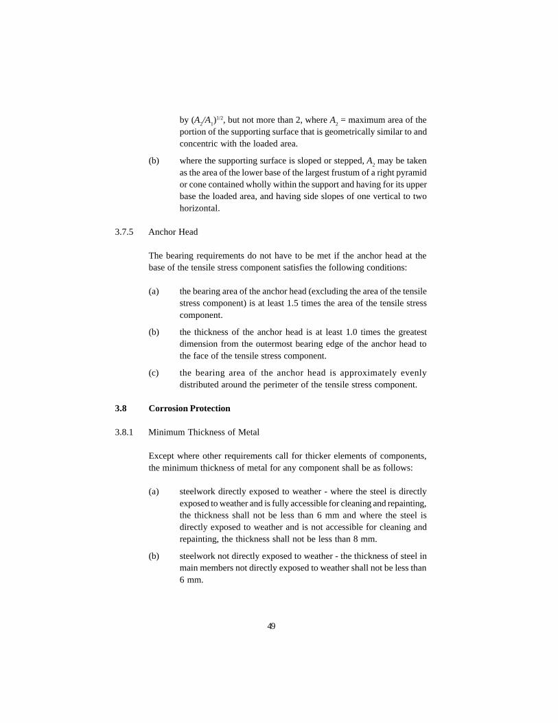
by (A2/A
1)1/2, but not more than 2, where A
2 = maximum area of the
portion of the supporting surface that is geometrically similar to andconcentric with the loaded area.
(b) where the supporting surface is sloped or stepped, A2 may be taken
as the area of the lower base of the largest frustum of a right pyramidor cone contained wholly within the support and having for its upperbase the loaded area, and having side slopes of one vertical to twohorizontal.
3.7.5 Anchor Head
The bearing requirements do not have to be met if the anchor head at thebase of the tensile stress component satisfies the following conditions:
(a) the bearing area of the anchor head (excluding the area of the tensilestress component) is at least 1.5 times the area of the tensile stresscomponent.
(b) the thickness of the anchor head is at least 1.0 times the greatestdimension from the outermost bearing edge of the anchor head tothe face of the tensile stress component.
(c) the bearing area of the anchor head is approximately evenlydistributed around the perimeter of the tensile stress component.
3.8 Corrosion Protection
3.8.1 Minimum Thickness of Metal
Except where other requirements call for thicker elements of components,the minimum thickness of metal for any component shall be as follows:
(a) steelwork directly exposed to weather - where the steel is directlyexposed to weather and is fully accessible for cleaning and repainting,the thickness shall not be less than 6 mm and where the steel isdirectly exposed to weather and is not accessible for cleaning andrepainting, the thickness shall not be less than 8 mm.
(b) steelwork not directly exposed to weather - the thickness of steel inmain members not directly exposed to weather shall not be less than6 mm.
49
3.8.2 Special Provisions
(a) Sealed sections shall have special protections against corrosion, suchas use of special paints or metal plating.
(b) For protection against chemical attack, added material thickness andother protections, as may be necessary, shall be provided.
50

4. SPECIAL REQUIREMENTS OF EMBEDDED PARTS
4.1 General
The provisions given herein and in sections 2 and 3 of this standard provideminimum requirements for design and anchorage of steel embedments usedto transmit loads from attachments into reinforced and pre-stressed concretestructures by means of tension, bearing, shear, friction, or any combinationpermitted therein.
4.1.1 The thickness of steel embedment plate and the number of anchors shall besuitably designed to prevent separation of plate from concrete surface as aresult of welding connections on to it for supports. Unless justified otherwise,the thickness of plate EPs should not be less than 10 mm.
4.1.2 The embedded parts on a containment structure shall satisfy the additionaldesign requirement that the leakage at interface of concrete and steel is limitedto a level as low as practical.
4.2 Expansion Anchors
4.2.1 The expansion anchors shall be selected so that they conform to the bestengineering judgement. For a component or equipment having a singleisolated support, there shall be a minimum of three expansion anchors. Underspecial circumstances, the number may be reduced to two if approved by thedesigner. Typical details of expansion anchors are shown in Figs. 2.1-3 and2.1-4.
4.2.2 Depending upon the type of arrangement and loading, the expansion anchorscan be subjected to tension or combined tension and shear. The expansionanchor shall be designed according to the loads transmitted to it. Therequirements of material shall be in accordance with cl. 2.6. The factor ofsafety over the forces under design load combinations shall not be less thanthe value recommended by the manufacturer.
4.2.3 Design Method
The design shall be as per the manufacturer’s catalogue or on the basis oftests.
4.2.4 Testing
Pullout, shear and combined pullout and shear tests shall be performed inaccordance with cl. 8.3.
51

5. SPECIAL REQUIREMENTS OF PENETRATION ASSEMBLIES
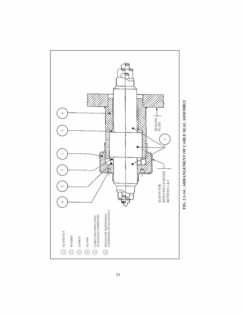
5.1 Electrical Penetration Assembly (EPA)
5.1.1 Cables entering the reactor building shall be appropriately sealed at the entryand exit points at both the outer containment wall, and inner containmentwall, to maintain containment integrity.
5.1.2 Each electrical penetration assembly at IC wall shall have a provision forperiodic testing at site in order to verify that the leak rate through the assemblyis within permissible limits, at the specified design pressure and at ambienttemperature.
5.1.3 Consideration should be given to accessibility of the electrical penetrationassembly for
l testing of the assembly after installation at site, and during servicelife;
l periodic maintenance or replacement of cable seal.
In certain cases where a structural wall concentric to a containment wall hasbeen provided, special arrangements may be required, as shown inFig.2.1-11.
5.1.4 Means shall be provided to accommodate thermal expansion/contraction ofthe cable and the components of the assembly.
5.1.5 The materials used in the electrical penetration assembly, when subjected toa radiation dose of specified value, shall maintain the physical and electricalproperties required to meet the service conditions.
5.1.6 The dielectric strength of the insulation of a cable at the penetration assemblyshall not be less than the value required for the voltage rating of that particularsystem.
5.1.7 The cable sealing arrangement at the EPA shall not degrade the performanceof a cable at the electrical penetration assembly below the acceptable limits.
Parameters like temperature rise of the cable at the electrical penetrationassembly shall be within acceptable limits.
52

5.1.8 Each penetration assembly shall be effectively grounded.
5.1.9 The assembly shall be designed to safely withstand the effects of short circuitcurrents flowing in a cable on account of a through fault external to theassembly.
5.1.10 Where applicable, the design should take into account effects ofelectromagnetic heating of the relevant components of the electricalpenetration assembly.
5.2 Mechanical Penetration Assembly
The mechanical penetration assembly can generally have the followingcomponents.
5.2.1 Guard Pipe Penetration
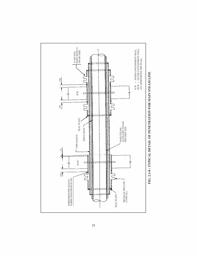
Where a guard pipe is required for a penetration assembly (ref. Fig. 2.1-8),the diameter of the guard pipe should be large enough to allow insulationaround the process line to fit in the annular space with adequate clearance.In case a rigid connection of the guard pipe to the flued embedment couldlead to overstressing of the attachment as a result of high loading causedduring an accident, the guard pipe should be equipped with bellows toaccommodate differential movements.
5.2.2 The design pressure of the guard pipe shall be assumed to be equal to thedesign pressure of the contained process pipe for the purpose of calculatingthe wall thickness of the guard pipe. The maximum operating pressure ofthe process pipe shall be considered in the calculation of reaction load on theconcrete structure from the guard pipe.
5.2.3 Bellows Expansion Joints
Where a single bellow is used in a mechanical penetration assembly on theprimary containment, a steel liner should be provided to protect the elementof the bellow against direct impingement of any jet in the event of a ruptureof the process pipe.
5.2.3.1 The bellows expansion joint, though providing for flexibility, must provide aleak-tight seal between the containment structure and the penetrationassembly.
53

5.2.3.2 The bellows shall be designed to withstand a specified number of cycles ofexpansion and compression due to thermal, seismic and other loads.
5.2.4 Insulation and Jacketing
5.2.4.1 Insulation should be provided to limit the rise of temperature in the structurearound the penetration assembly. Regardless of the amount of temperaturereinforcement, the concrete temperature shall not exceed the values givenbelow over a long term period (during normal operation or post-accidentconditions over prolonged periods):
(a) Large areas : 65°C.
(b) Local areas : 95°C.
5.2.4.2 For penetrations, which require in-service inspection of welds, the insulationand protective covering shall be designed so as to permit easy removal andreinstallation.
5.2.5 Ring Sealing Device
For the purpose of air testing of penetration assemblies, independent of thepressure test of the containment, the penetration assemblies may be providedwith removable sealing devices of the split-ring type.
5.3 Fire Resistant Design
5.3.1 Penetration EPs should be protected, where required, against fire hazard,either by a fire resistant design or by passive provisions such as fire resistantcoatings, intumescent paints, barriers, etc.
5.3.2 The design criteria for fire resistance should be such that the componentssustain their integrity against a fire of specified intensity and period.
5.3.3 Where the fire resistant design approach is adopted, the design basis fireshall correspond to that which may develop from the fire load in a given firezone.
5.3.4 Where fire rating approach is adopted, the rating of different structuralcomponents to be considered in the design shall comply with the requirements
54

of safety standard, ‘Civil Engineering Structures Important to Safety of NuclearFacilities’, No.AERB/SS/CSE.
5.3.5 Subsequent to a major fire, the EPs or penetrations in the affected areasshould be surveyed to assess possible deterioration/serviceability.
5.3.6 A classification of EPs in the reactor buildings of Indian PHWRs for fireresistance consideration is given in Annexure-I (ref.: NPCIL (1994), Reportof the Committee on Fire Resistance Requirements for EPs in Reactor Buildingand Containments of Indian PHWRs, June 1994).
55

6. FABRICATION AND INSTALLATION REQUIREMENTSOF EMBEDDED PARTS, PENETRATION ASSEMBLIES
AND THEIR COMPONENTS
6.1 General
Penetration assemblies shall be fabricated and installed in accordance withthe requirements of this section. The requirements shall depend on whetherthe fabrication is done in a shop or at the field. Unless otherwise indicated,the term component shall be understood to include parts and appurtenancesof the penetration assembly.
6.1.1 If, during fabrication of the component, the material is subjected to conditionswhich cause a change in the principal characteristics that have not beenaccounted for in the design and that may change any property from thespecified value, the design tests shall be repeated or additional tests made forthe purpose of acceptance.
6.1.2 As far as possible, piping and cable penetrations through primary containmentshould have provisions for leak checks during in-service containment leaktesting. However, it is recognised that closure panels for openings in thecontainment for installation of steam generators (SGs) can only be checkedduring testing for containment integrity and in-service leak rate.
6.2 Fabrication and Installation
6.2.1 The practices followed in fabrication and installation of containmentstructures, penetration assemblies and appurtenances shall be consistent withthe overall objective of achieving high reliability of containment integrity.Due care shall be taken in certification of the materials, cleanliness andqualification of fabrication processes including requirements of heat treatment,etc. Adequate inspection and testing coverage shall be given to all fabricatedparts to build up assurance.
Fabrication, installation and examination as per ASME Section III, Division1, NE-4000/5000 for metal containment and ASME Section III, Division 2,CC-4500, 4600, 5500, 5600 for concrete containment are adequate to meetthe objective of this clause.
56

6.2.2 Fabrication and erection of EPs for other structures shall comply with therequirements for AERB Standard No. AERB/SS/CSE-2.
6.2.3 The embedded parts and penetration assemblies shall be installed followinga well laid out procedure which will prevent any damage to the assemblyduring its installation and concreting. All fabricated items shall be installedonly after their inspection and acceptance. EPs shall not be supported to thestructural reinforcement by welding during concreting.
6.2.4 The anchorage systems, such as grouted anchors, expansion anchors andinserts used to support:
(a) seismically qualified equipment,
(b) special components, and
(c) vibrating and rotating equipment
shall be installed by qualified personnel following well-defined constructionand installation procedures, as a safeguard against any possible failure dueto unplanned workmanship.
57

7. QUALITY ASSURANCE
7.1 General
7.1.1 A Quality Assurance Programme (QAP) pertaining to EP, penetrationassemblies and attachments covering all phases of activities shall be developedand implemented so as to achieve adequate assurance of quality and safety.The Responsible Organisation (RO) shall ensure that overall QAP satisfiesthe requirements of Code of Practice on Quality Assurance (QA) for Safetyin Nuclear Power Plants, AERB/SC/QA and section 9 of AERB SafetyStandard No. AERB/SS/CSE.
7.1.2 The QAP shall contain details in respect of the following :
- Policy
- Management
- Performance function
- Quality control, which broadly includes verification and correctivefunctions
- Documentation
7.1.3 For items not covered by this standard, the quality assurance requirementsshall be developed in accordance with the guidelines of the standard on QualityAssurance for Construction of Civil Engineering Structures Important toSafety of Nuclear Facilities, AERB/SG/CSE-3.
7.2 Verification
The methods of acceptance may include source verification, inspection onreceipt, suppliers’ certificate of conformance, post installation tests, or aconfirmation thereof.
7.3 Non-Conformance
The owner/purchaser should develop procedures for identification, controland disposition of documents, items and services, which do not meet thespecified requirements. The procedures for control of non-conformance anddisposition shall contain provisions for dealing with matters like:
58

(a) review of non-conformance;
(b) decision regarding acceptance or corrective measures for each item;
(c) verification of disposition and implementation of corrective mesures;
(d) maintenance of records of non-conformances and modifications tobase documents so as to provide as-built information.
7.4 Calculations
Calculations related to the design and analysis of EPs shall be welldocumented, listing all assumptions made in the design. The source of inputdata used in the calculations shall be adequately referenced so that all dataare readily traceable. When a computer aided analysis and design is adopted,the analysis and design assumptions, input data and output results should bemade part of the calculations. The calculations shall be checked independently.
7.5 Drawings
Copies of EP drawings and specifications shall be approved and signed bythe authorised engineer.
7.6 Surveillance and In-service Inspection
7.6.1 Surveillance
The surveillance and test requirements, forming a part of the performancefunction, shall in general, meet the requirements of the following:
(a) AERB/SG/O-2 In-service Inspection of Nuclear Power Plants
(b) AERB/SG/O-7 Maintenance of Nuclear Power Plants
(c) AERB/SG/O-8 Surveillance of Items Important to Safety inNuclear Power Plants
(d) ASME Boiler and Pressure Vessel Code, Section XI
(e) AERB/SG/CSE-3 Quality Assurance for Construction of CivilEngineering Structures Important to Safety ofNuclear Facilities
59

7.6.2 In-Service Inspection
A list of all items, which will require in-service inspection, shall be preparedalong with identification of the parameters, which will require in-serviceinspection. The design of the penetrations and EPs shall give carefulconsideration to provide access to both visual and non-destructive in-serviceinspection of the penetration components. The requirements of and theprocedures for such inspections shall be in accordance with the requirementsof the ASME Boiler and Pressure Vessel Code, Section XI and AERB SafetyManual ‘In-Service Inspection of Civil Engineering Structures Important toSafety of Nuclear Power Plants’, AERB/SM/CSE-2.
7.7 Data and Documentation
Data for penetration assemblies shall be recorded and maintained as part ofQA documentation. Any modification or revision at any stage shall be recordedby the owner. The data of penetration assemblies shall cover the followingas a minimum:
(a) manufacturer’s name and year of manufacture;
(b) unique identification number;
(c) qualified radiation life (qualified life under radiation in the radiationfield of placement);
(d) list of replacement components along with time required forreplacements;
(e) design pressure;
(f) continuous maximum temperature under normal conditions;
(g) radiation type and integrated dose, as applicable to the location;
(h) for electrical penetration assembly:
(i) rated voltage,
(ii) rated continuous current,
(iii) rated short-time overload current and duration,
(iv) rated short-circuit current where applicable,
(v) continuous temperature design limits for electrical insulation.
60
8. TESTING
8.1 General
8.1.1 When it is not possible to qualify by analysis, EPs shall be tested underdesign load combinations to demonstrate that these will develop the designstrength and the deformations will be within the specified limit.
8.1.2 Specimens used in qualification tests of EPs shall meet the followingrequirements:
(a) it shall be of the same generic design as that of the production units.
(b) it shall be manufactured using production facilities and processeswhich are representative of those used for production units.
(c) it shall have such shape and configuration that will stimulate thermal,electrical and mechanical stresses as stipulated in the design underqualification.
8.1.3 In order to verify that the penetration assembly meets the specifiedrequirements and will operate satisfactorily, the assembled unit shall be testedfor all the specified loading conditions to the extent possible. However, whenit is not possible to perform full load testing and for specially designed tailor-made EPs, qualification by analysis will be acceptable.
8.1.4 The requirements of instrumentation, acceptance criteria, leakage ratecalculations, etc., pertaining to proof and leakage rate testing of penetrationsare covered in safety guide ‘Proof and Leakage Rate Testing of ReactorContainments’, AERB/SG/O-16.
8.2 Anchors
8.2.1 Anchors shall be tested to verify the ability of the anchor mechanism todevelop the required tensile strength.
8.3 Installed Expansion Anchors, Grouted Anchors and Inserts
8.3.1 This clause covers the requirements for in-situ testing of grouted anchors,expansion anchors and inserts used to support:
61
(a) seismically qualified equipment,
(b) special component, and
(c) vibratory and rotating equipment.
8.3.2 Anchorage systems where workmanship could be a possible cause of failure,shall be tested as follows:
(a) the system shall be tested to a static tensile force equal to 75 percentof the specified yield strength of the bolt.
(b) one unit of each operator’s weekly anchorage production or one ofeach 50 consecutively installed anchorages of each type, whicheveris less, shall be selected at random for testing.
8.3.3 Anchors that fail in the test shall be removed and replaced. In addition, twoadjacent anchors or two anchors chosen at random from the same groupshall be tested. Should the additional anchors too fail in the test, furtherinstallation shall be stopped unless corrective action is taken and theinstallation procedure is requalified.
8.4 Tests on Electrical Penetration Assembly
8.4.1 Tests on Electrical Penetration Assemblies (EPA) and components can beclassified as follows:
(a) typical and routine tests conducted by the manufacturer to ensurethat the assembly and its components meet the design intent and thequality requirement of workmanship.
(b) field testing at site.
8.4.2 Typical tests are performed on representative samples to verify the adequacyof the design. These tests on EPA and its components can include the followingtests:
(a) verification of chemical composition and key mechanical propertiesof the main materials used in the EPA.
(b) cumulative radiation dose-withstanding capability of the mainprimary insulating materials. The value for cumulative radiationdose used during type testing should include a margin. This marginshould not be less than 10 percent of the accident dose used.
62

(c) gas leak rate test on representative assembly should be carried outusing nitrogen. The pressure for leak test shall be same ascontainment test pressure.
(d) thermal ageing tests should be conducted on important insulatingmaterials and gaskets in order to assess their qualified life. The testneed not be carried out on items in use showing satisfactory operatingexperience.
(e) the electrical penetration assembly should safely withstand the effectsof category I seismic conditions. The seismic withstanding capabilityof EPA should be established either by testing or by analysis or bycombination of both. The seismic qualification procedure shouldtake into account the presence of cables passing through the EPA.
8.4.3 Routine tests are performed on all components, sub-assemblies or assembliesas required, to verify the quality of workmanship. Routine inspection of EPAand its components shall include the following tests:
(a) verification of dimensions;
(b) visual inspection .
8.4.4 Field testing at site shall/should include the following tests:
(a) measurement of insulation resistance of each core of the cablesprovided with core sealing or strand sealing.
(b) leak rate test should be conducted on each assembly, with compressedair at appropriate pressure. Provision for periodic in-service leakcheck with compressed air should be provided on each electricalpenetration assembly for ascertaining its integrity in service.
8.5 Field Testing of Mechanical Penetration Assemblies
8.5.1 The penetration assembly shall be tested in accordance with ASME Boilerand Pressure Vessel Code. For metal containment, the requirements ofDivision 1, Section III, sub-section NE for class MC components and forconcrete containment, relevant requirements of Section III, Division 2 of thesame ASME Code should be complied with.
63

8.5.2 Mechanical penetration assemblies having double bellows/seals shall haveprovisions for the pneumatic leak test. The pneumatic pressure test shall beconducted at a pressure not less than 1.1 times the design pressure of thepenetration assembly. The pressure shall be maintained for a minimum of10 minutes and the leakage should be less than the specified value.
8.6 Special Tests
8.6.1 Seismic Qualification Test
Embedded inserts and expansion anchors used to support seismically qualifiedequipment shall be seismically qualified. A minimum of three specimens,randomly selected, shall be tested in cyclic tensile loading and shear loading.The frequency and sequence of cyclic loading shall be given by the designer.The material for the test shall be identical to the embedment material to beused in the actual application.
8.6.2 Tests for Qualified Life
Tests should be performed to assess the qualified life of the product of eachgeneric design using acceptable methods. These tests may be necessary wherequalified life cannot be conveniently determined by analytical methods.
64

ANNEXURE - I
CLASSIFICATION OF REACTOR BUILDING EPs FOR FIRERESISTANCE
I-1 From fire resistance point of view, reactor building EPs could be divided intocertain categories as follows:
Category - I : Through-wall EPs in inner containment.
Category - II : Through-wall EPs in outer containment.
Category - III : Through-wall EPs in internal walls and floorsof the reactor building.
Category - IV : Non-through-wall EPs.
I-2 Category-I : EPs
Through-wall EPs in the inner containment wall are mostly for allowing thepassage of pipes, ducts and cables through the containment wall. The otherkind of EPs are for main and emergency airlocks, which allow access to thereactor building for movement of men and materials and the dome closureEPs which are permanently sealed after initial installation of equipment.
I-2.1 Category-I : Conduit EPs
The EPs which convey rigid conduits like pipes and ducts through containmentwall are generally steel circular sections embedded in the wall and sealed bybellows on both ends, welded between the conduit and the EP. The bellowsare required to accommodate movement of pre-stressed concrete innercontainment wall due to pressure, thermal shrinkage, creep and seismic effects,along with maintaining a leak-tight containment boundary.
The containment should be considered as a fire barrier to limit theconsequences of a fire from the view point of three considerations:
1. stop an external/internal fire from spreading inside/outside.
2. maintain structural integrity during fire.
3. provide a fire compartment totally surrounding the reactor systems.
65

As part of the containment, the EPs will be required to act as a flame stop fromthe first consideration. Flame stop would mean that as an assembly, the EPshould not allow flame travel from the face to which it is applied, to the otherunexposed face, i.e. if flame is applied to the inner bellow it should not emergefrom the outer bellow. The flame could only pass through if both inner andouter bellows get punctured. Absence of puncture in any one bellow wouldstop the flame.
The structural integrity requirement for containment during fire is notinfluenced by EPs, as they do not serve a structural function in thecontainment; they are sealing units in this case. Also, the fire compartmentrequirement of the containment is met if EPs act as flame stop. Thus, therequirement for ICW (Inner Containment Wall) bellows for fire resistanceshould be the absence of puncture in any one of the two bellows, when anyone of them is exposed to flame. After any significant fire event, the affectedEPs will however be required to be examined for serviceability to ascertaincontainment integrity during operation.
I-2.2 Category-I : Cable EPs
The EPs which serve as cable passages are different from conduit EPs sincethe former do not employ bellows. The cable is continuous through the EP inthe ICW in Indian PHWRs, unlike LWR containments where cables terminateon the EP plates on both sides of the wall and a separate feed through connectsboth the ends. As per the practice followed in Indian PHWRs, the standardconductor is crimped to make it solid and the cable is moulded in an epoxycompound to seal the gaps between the cores, sheath and conductor. Further,the sealing between the sealing plate and cable is provided by passing thecable through a gland and nut assembly with necessary gaskets.
The EP itself is a rectangular box section embedded inside the ICW withclosure plates at both ends to which glands are welded for passage of cablesas described above. As discussed for conduit EPs, the requirements during afire for the EPs would be to act as a flame stop. In case of cable EPs thiswould require that the sealant compound should not propagate the flame, asthis sealant is blocking the flame passage between the metal wires and themetal EP plate. A sealant compound tested for the required flame-proofcharacteristics would be required for this.
66

Another way of fire propagation through cable would be the heating of metalwires in the cable in the area exposed to flame and conduction of this heatvia metal wires to the other side of EP, possibly igniting the sheath. To counterthis type of fire propagation, the cables on both sides of the EP will have tobe coated by fire retardant material for a suitable length.
I-2.3 Category-I : Airlock EPs
The description given below is applicable only for new designs of 220 MWePHWRs- Kaiga onwards. However, the general principles related to fire safetyare also applicable to 500 MWe design which follows a two-door concept forall the three airlocks (additional airlock for F/M movement) and does nothave a separate structural wall inside the containment.
There are two airlocks in the containment, main air lock (MAL) andemergency air lock (EAL). Large circular EP is located in the ICW to providespace for the airlock barrel to pass through. The space between the airlockbarrel and the EP is sealed by a large circular bellow, welded to EP on outsideand a flange on the barrel on the inside. Unlike conduit EPs, there is onlyone sealing bellow on the ICW, while the other sealing bellow is on OCW(Outer Containment Wall). The airlock barrel, which passes through theEPs starts from the structural wall inside the containment. The barrel isfixed to the structural wall by a bolted connection, which is not a sealedpoint, but only has a very narrow leak path. Inside the barrel there are threedoors which divide it into two compartments, the inner (towards containment)and the outer (away from containment). At any time when men or equipmentare passing through the airlock, three conditions may exist:
1. inner compartment in communication with inner containment.
2. inner compartment and outer compartment in communication.
3. outer compartment in communication with outside.
The above discussion is intended for considering the paths available for flametravel through the EP and the barrel. Considering a fire inside the containment,the flame path outside the barrel would be through the bolted joint of thebarrel to the structural wall and then the EP bellow. It is considered here thatin the space between the structural wall and ICW in this area, there is nothingflammable. This path has two obstructions and a large distance separatingthem. Thus, for the steel bellow, there is no possibility of any direct flame
67

impingement. Besides, the areas in the containment in front of these airlocksare required to be kept free for movement of personnel and equipment. Assuch, any significant fire in these areas is ruled out. Apart from the above,airlocks also serve as escape routes for persons trying to come out in case ofa fire and provide access for manual fire-fighting by the fire personnel. Thus,any requirements of a sealed fire barrier or fire stop cannot be strictly appliedto the airlock doors.
However, even as a remote eventuality if a fully-developed fire inside thecontainment in front of an airlock was to be considered from the flame travelpoint of view, the neoprene rubber seals of the doors are the elements whichmay give way. But because of large distance between the doors and the absenceof any flammable material between them, it is unlikely that flame wouldcross via this path. The same would apply for flame travel in the oppositedirection.
I-2.4 Category-I : Dome sealing EPs
These EPs are steel circular rings, to which steel dished ends are welded,sealing the openings kept in ICW and OCW to allow passage of SGs (steamgenerators), whenever required. The requirement for these EPs is to act as aflame stop, which would be the case as they are full steel sections.
I-3 Category-II : EPs
These are the EPs, which are located in OCW (outer containment wall).Most of these are corresponding EPs to those in ICW, as the same pipes,ducts and cables which pass through ICW also pass through OCW. At manylocations, the corresponding EPs in ICW and OCW are offset to avoid possibleradiation streaming. The MAL, EAL and dome EPs of ICW also havecorresponding OCW EPs. Apart from these, there are some large EPs inOCW only. These are closable doors for approaching the annular space. TheICW-OCW annulus space is a leak-tight envelope surrounding thecontainment, designed for low excess pressure.
As described above, the ICW is considered a fire barrier, which completelysurrounds the reactor and associated systems. The OCW need not beconsidered as a fire barrier. The only requirement to be met by the OCWwould be maintaining structural integrity in event of a fire. This would berequired from the consideration that many pipes, cables and ducts are
68

supported or passing through the wall and its collapse may cause their failureor may cause damage to the ICW.
As far as the flame stop requirements are concerned for OCW EPs, it is notstrictly needed, because ICW EPs are to serve as flame stops. However,precautions are taken in OCW EPs to ensure that an external fire coming inannular space via an EP would not propagate in the annular space to engulfa large area. This would require enough separation and avoiding cross-connections of cables between EPs.
Another solution would be to put flame stops for OCW EPs on the outsideface (away from the containment). In this case flame stops on ICW outerface would not be necessary. Flames propagating outwards from inside thecontainment would be stopped at the structural wall and the flamespropagating from outside the containment to inside would be stopped by theOCW outer face flame stop. However, an initiation of fire in the annularspace would still require the precautions against spread of fire in the annularspace to be effective.
I-4 Category-III : EPs
Through-wall EPs in internal walls and floors of the reactor building, whichseparate fire areas, should be provided with appropriate fire-resistant sealant.
I-5 Category-IV : EPs
Fire-resistance rating of these EPs is not relevant.
69
BIBLIOGRAPHY
1. AMERICAN CONCRETE INSTITUTE, Code Requirements for NuclearSafety Related Concrete Structures (ACI 349-85) and Commentary (ACI349 R-85), Detroit, Michigan (1985).
2. AMERICAN SOCIETY OF MECHANICAL ENGINEERS, Class MCComponents, ASME Boiler and Pressure Vessel Code, Section III, Rules forConstruction of Nuclear Power Plant Components, Division 1 - SubsectionNE (1986).
3. AMERICAN SOCIETY OF MECHANICAL ENGINEERS, ComponentSupports, ASME Boiler and Pressure Vessel Code, Section III, Rules forConstruction of Nuclear Power Plant Component, Division 1 - Sub-sectionNF (1989).
4. ATOMIC ENERGY REGULATORY BOARD, Safety Standard for NuclearSafety Related Civil Engineering Structures, AERB Safety Standard No.AERB/SS/CSE, Mumbai, India (1998).
5. ATOMIC ENERGY REGULATORY BOARD, Code of Practice on QualityAssurance for Safety in Nuclear Power Plants, AERB Safety Code No. SC/QA, Mumbai, India (1988).
6. ATOMIC ENERGY REGULATORY BOARD, Design of Concrete StructuresImportant to Safety of Nuclear Facilities, AERB Standard No. AERB/SS/CSE-1, Mumbai, India (2002).
7. ATOMIC ENERGY REGULATORY BOARD, Design, Fabrication andErection of Steel Structures Important to Safety of Nuclear Facilities, AERBStandard No. AERB/SS/CSE-2, Mumbai, India (2002).
8. ATOMIC ENERGY REGULATORY BOARD, Design of Nuclear Power PlantConcrete Containment Structures, AERB Standard No. AERB/SS/CSE-3,Mumbai, India. (under preparation)
9. CANADIAN STANDARDS ASSOCIATION, Design Requirements forConcrete Containment Structures for CANDU Nuclear Power Plants, CAN3-N287.3-M82 (1982).
70

10. CANADIAN STANDARDS ASSOCIATION, Material Requirements forConcrete Containment Structures for CANDU Nuclear Power Plants, CAN3-N287.2-M82 (1982).
11. THE INSTITUTE OF ELECTRICAL AND ELECTRONICS ENGINEERSINC., IEEE Standard for Electrical Penetration Assemblies in ContainmentStructures for Nuclear Power Generating Stations, New York (1984).
12. THE INSTITUTE OF ELECTRICAL AND ELECTRONICS ENGINEERSINC., IEEE Standard for Installation, Inspection and Testing Requirementsfor Class 1E Instrumentation and Electric Equipment of Nuclear PowerGenerating Stations, New York (1980).
13. NUCLEAR POWER CORPORATION OF INDIA LIMITED, Report of theCommittee on Fire Resistance Requirements for EPs in Reactor Buildingand Containments of Indian PHWRs, June 1994.
71

LIST OF PARTICIPANTS
CODE COMMITTEE FOR CIVIL AND STRUCTURAL ENGINEERING(CCCSE)
Dates of meeting : January 22 & 23, 1998February 8 & 9, 1999December 14 & 15, 1999
Members of CCCSE:
Shri N.N. Kulkarni (Chairman) : Consultant, AERB
Prof. V.N. Gupchup : Pro Vice-Chancellor (Retd.),Mumbai University
Director (Civil) : Bureau of Indian Standards, New Delhi
Dr. A. Dasgupta : DCL, Calcutta
Shri R.B. Gunde : Engineering Manager, TCE, Hyderabad
Shri A.S. Warudkar : NPCIL, Mumbai
Dr. P.C. Basu : Head, C&SED, AERB, Mumbai
Shri L.R. Bishnoi : C&SED, AERB, Mumbai(Permanent Invitee since 27.7.1997)
Members of Sub-Committee Constituted by CCCSE:
Shri V.K. Sharma : NPCIL, Mumbai
Shri K.B. Dixit : NPCIL, Mumbai
Shri K.K. Vaze : BARC, Mumbai
Shri M.K. Kannan : NPCIL, Mumbai
Shri K.P. Dwivedi : NPCIL, Mumbai
72

ADVISORY COMMITTEE ON NUCLEAR SAFETY (ACNS)
Date of meeting : September 30, 2000
Members of ACNS:
Shri S.K. Mehta (chairman) : BARC (Former)
Shri S.M.C. Pillai : Nagarjuna Power Corporation,Hyderabad
Prof. U.N. Gaitonde : IIT, Bombay
Shri S.K. Goyal : BHEL, Hyderabad
Shri Ch. Surendar : NPCIL (Former)
Dr. U.C. Mishra : BARC (Former)
Shri S.K. Sharma : BARC
Dr. V. Venkat Raj : BARC
Shri S.P. Singh : AERB (Former)
Shri G.K. De : AERB (Former)
Shri K. Srivasista : AERB(Member-Secretary)
73

LIST OF CIVIL AND STRUCTURAL ENGINEERINGSTANDARDS, GUIDES AND MANUALS
Safety Series Nos. Title
Safety Standards
AERB/SS/CSE Civil Engineering Structures Important to Safety of NuclearFacilities
AERB/SS/CSE-1 Design of Concrete Structures Important to Safety of NuclearFacilities
AERB/SS/CSE-2 Design, Fabrication and Erection of Steel Structures Importantto Safety of Nuclear Facilities
AERB/SS/CSE-3 Design of Nuclear Power Plant Containment Structures
AERB/SS/CSE-4 Design, Fabrication and Erection of Embedded Parts andPenetrations Important to Safety of Nuclear Facilities
Safety Guides
AERB/SG/CSE-1 Seismic Analysis and Qualification of Structures, Systems,Equipment and Components Important to Safety of NuclearFacilities. (Being prepared by ACCGD as AERB/SG/D-23)
AERB/SG/CSE-2 Geotechnical Aspects for Buildings and Structures Importantto Safety of Nuclear Facilities
AERB/SG/CSE-3 Quality Assurance for Construction of Civil EngineeringStructures Important to Safety of Nuclear Facilities
AERB/SG/CSE-4 Materials of Construction for Civil Engineering StructuresImportant to Safety of Nuclear Facilities
74

LIST OF CIVIL AND STRUCTURAL ENGINEERINGSTANDARDS, GUIDES AND MANUALS (contd.)
Safety Series Nos. Title
Safety Manuals
AERB/SM/CSE-1 Maintenance of Civil Engineering Structures Important toSafety of Nuclear Power Plants
AERB/SM/CSE-2 In-Service Inspection of Civil Engineering StructuresImportant to Safety of Nuclear Power Plants
AERB/SM/CSE-3 Construction Methodology for Civil Engineering StructuresImportant to Safety of Nuclear Facilities
AERB/SM/CSE-4 Civil Engineering Construction Inspection of StructuresImportant to Safety of Nuclear Facilities
AERB/SM/CSE-5 Format of Safety Design Reports
75

Published by: Atomic Energy Regulatory Board,
Niyamak Bhavan, Anushaktinagar.
Mumbai – 400 094
AERB SAFETY STANDARD NO. AERB/NF/SS/CSE-4