Embed Size (px)
Citation preview
PROJECT MANUAL SIUC GIR # 16104 BRIC PROJECT # 920-13HHJ SIUC Building # 0142
REPLACE HOT AND CHILLED WATER PIPING Neely Hall Southern Illinois University Carbondale, Illinois
CONTRACTS: HEATING BY: BRiC Partnership, LLC 100 East Washington Street Belleville, Illinois 62220 Date: December 8, 2016
SIUC: #16104 00 01 10-1 Replace Hot and Chilled Water Piping BRiC: 920-13HHJ Neely Hall
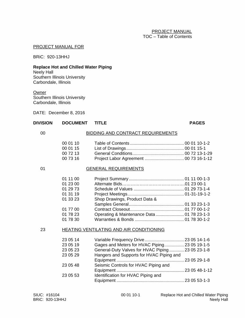
PROJECT MANUAL TOC – Table of Contents PROJECT MANUAL FOR BRiC: 920-13HHJ Replace Hot and Chilled Water Piping Neely Hall Southern Illinois University Carbondale, Illinois Owner Southern Illinois University Carbondale, Illinois DATE: December 8, 2016 DIVISION DOCUMENT TITLE PAGES 00 BIDDING AND CONTRACT REQUIREMENTS 00 01 10 Table of Contents ............................................ 00 01 10-1-2 00 01 15 List of Drawings ............................................... 00 01 15-1 00 72 13 General Conditions .......................................... 00 72 13-1-29 00 73 16 Project Labor Agreement ................................ 00 73 16-1-12 01 GENERAL REQUIREMENTS
01 11 00 Project Summary ............................................. 01 11 00-1-3 01 23 00 Alternate Bids…………………………………….01 23 00-1 01 29 73 Schedule of Values ......................................... 01 29 73-1-4 01 31 19 Project Meetings .............................................. 01-31-19-1-2 01 33 23 Shop Drawings, Product Data & Samples General ............................................. 01 33 23-1-3 01 77 00 Contract Closeout ............................................ 01 77 00-1-2 01 78 23 Operating & Maintenance Data ....................... 01 78 23-1-3 01 78 30 Warranties & Bonds ........................................ 01 78 30-1-2 23 HEATING VENTILATING AND AIR CONDITIONING 23 05 14 Variable Frequency Drive ................................ 23 05 14-1-6 23 05 19 Gages and Meters for HVAC Piping ................ 23 05 19-1-5 23 05 23 General-Duty Valves for HVAC Piping ............ 23 05 23-1-8 23 05 29 Hangers and Supports for HVAC Piping and
Equipment ....................................................... 23 05 29-1-8 23 05 48 Seismic Controls for HVAC Piping and Equipment ....................................................... 23 05 48-1-12 23 05 53 Identification for HVAC Piping and Equipment ....................................................... 23 05 53-1-3

SIUC: #16104 00 01 10-2 Replace Hot and Chilled Water Piping BRiC: 920-13HHJ Neely Hall
23 05 93 Testing, Adjusting, and Balancing for HVAC ... 23 05 93-1-8 23 07 00 HVAC Insulation .............................................. 23 07 00-1-11 23 09 00 HVAC Instrumentation and Controls ............... 23 09 00-1-29 23 09 00A HVAC Instrumentation and Controls Appendix A ...................................................... 23 09 00A-1-3 23 21 13 Hydronic Piping ............................................... 23 21 13-1-13 23 21 23 Hydronic Pumps .............................................. 23 21 23-1-5 26 ELECTRICAL 26 05 19 Building Wire & Cable ..................................... 26 05 19-1-5 26 05 26 Grounding & Bonding for Electrical Systems... 26 05 26-1-3 26 05 29 Supporting Devices ......................................... 26 05 29-1-2 26 05 32 Cabinets & Enclosures .................................... 26 05 32-1-2 26 05 33 Conduit ............................................................ 26 05 33-1-5 26 05 35 Boxes .............................................................. 26 05 35-1-3 26 05 53 Identification for Electrical Systems ................. 26 05 53-1-3 26 24 16 Panelboards .................................................... 26 24 16-1-3 26 28 16 Enclosed Switches .......................................... 26 28 16-1-2 26 29 13 Enclosed Motor Controllers ............................. 26 29 13-1-4 SPECIFIERS: BRiC Partnership, LLC 618-277-5200 HVAC: Andy Rein [email protected] Electrical: Jeff Nolte [email protected]
SIUC: #16104 00 01 15-1 Replace Hot and Chilled Water Piping BRiC: 920-13HHJ Neely Hall
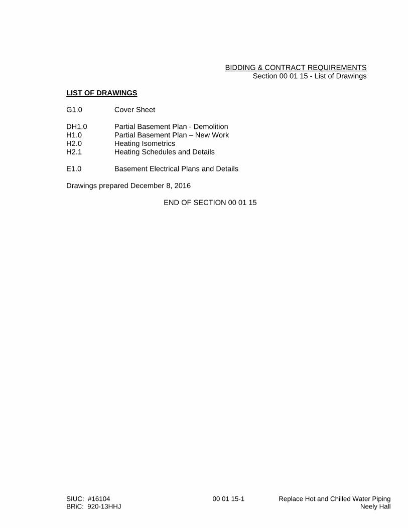
BIDDING & CONTRACT REQUIREMENTS Section 00 01 15 - List of Drawings LIST OF DRAWINGS G1.0 Cover Sheet DH1.0 Partial Basement Plan - Demolition H1.0 Partial Basement Plan – New Work H2.0 Heating Isometrics H2.1 Heating Schedules and Details E1.0 Basement Electrical Plans and Details Drawings prepared December 8, 2016
END OF SECTION 00 01 15
A Guide to the
General Conditions For Bidding on Construction Contracts with Southern Illinois University Carbondale Revised October 2013

SIUC: #16104 00 72 13-1 Replace Hot and Chilled Water Piping BRiC: 920-13HHJ Neely Hall
GENERAL CONDITIONS Table of Contents Article 1. Bid Documents Page 1 Article 2. Conditions or Qualifying Statements Page 3 Article 3. Bid Security (Bid Bond) Page 3 Article 4. Insurance Page 4 Builder's Risk Requirements Page 6 Article 5. Indemnification Page 9 Article 6. Visiting the Site Page 10 Article 7. Substitutions Page 10 Article 8. Acceptance or Rejection of Proposals Page 12 Article 9. Withdrawal of Proposals Page 12 Article 10. Taxes Page 12 Article 11. Labor Page 13 Article 12. Rate of Wages for Workers Page 13 Article 13. Nondiscrimination of Employment Page 14
Equal Employment Opportunity Article 14. Illinois Human Rights Act Page 16 Article 15. Foreign Corporations Page 16 Article 16. Royalties and Patents Page 16 Article 17. Permits and Regulations Page 17 Article 18. Time of Commencement and Completion Page 17 Article 19. List of Subcontractors Page 17 Article 20. Intent of Documents Page 18 Article 21. Shop Drawings Page 18 Article 22. Materials, Appliances, Employees Page 19 Article 23. Protection of Work and Property Page 19 Article 24. Working Regulations Page 19 Article 25. Use of Site Page 20 Article 26. Protection of Trees, Shrubs and Planting Page 20 Article 27. Cleaning up Page 20 Article 28. Damages Page 21 Article 29. Mutual Responsibility of Contractors Page 21 Article 30. Coordination and Cooperation Page 21 Article 31. Inspection of Work Page 21 Article 32. Foreman Supervision Page 21 Article 33. Change in the Work Page 22 Article 34. Deductions for Uncorrected Work Page 22 Article 35. Owner's Right to do Work Page 22 Article 36. Assignments Page 22 Article 37. Labor and Wage Record Page 22 Article 38. Application for Payments and Payment to Contractors Page 22 Article 39. Liens Page 23 Article 40. Compliance with "Kick-back Statute" and Regulations Page 23 Article 41. Guarantees Page 24 Article 42. Liquidated Damages Page 24 Article 43. Starting of Systems Page 24 Article 44. Training Page 24 Article 45. Record Documents Page 25
SIUC: #16104 00 72 13-2 Replace Hot and Chilled Water Piping BRiC: 920-13HHJ Neely Hall
Article 46. Steel Products Procurement Act Page 25 Article 47. Termination of Contract Page 25
SIUC: #16104 00 72 13-1 Replace Hot and Chilled Water Piping BRiC: 920-13HHJ Neely Hall
1
GENERAL CONDITIONS FOR BIDDING ON CONTRACTS WITH SOUTHERN ILLINOIS UNIVERSITY CARBONDALE ARTICLE 1. Bid Documents All bidding, proposals, offers and procurement will be conducted in accordance with the Procurement Rules of the Chief Procurement Officer for Public Institutions of Higher Education, which have been adopted pursuant to the Illinois Procurement Code. All respondents will be strictly held to these statutes and rules and they are considered incorporated herein by reference as if attached hereto. The Respondent remains solely responsible for insuring that its Proposal is received at the time, date, place, and office specified. AVAILABILITY OF DOCUMENTS
All State Universities in Illinois publish their competitive Bid/RFP and other procurement notices, as well as award information at: http://www.procure.stateuniv.state.il.us
Suppliers intending to respond to any posted requirement are encouraged to visit that site to insure that they have received a complete and current set of documents. Some notices may provide a downloadable copy of the pertinent procurement documents, as well as any amendments to those documents. Additionally, some notices may permit a supplier to submit a response to a posted requirement in an electronic format. Any supplier receiving a copy of procurement documents from a bid referral service and/or other third party is solely responsible for insuring that they received all necessary procurement documentation, including amendments. Interested suppliers should note that the State Universities in Illinois do not charge any fees (except any required surety documents) to obtain a copy of or respond to documents posted for competitive solicitation. The issuing University is not responsible for insuring that all or any procurement documentation is received by a supplier that is not appropriately registered with the issuing University. Bid proposals shall be executed and submitted on the form/s provide by the Director of Procurement Services of Southern Illinois University Carbondale. Only the Request for Quotation and attachments (if any) are to be returned. The sealed bid (proposal) shall be delivered to Procurement Services, 113 Wakeland Hall, Room 103, Mailcode 6813 1215 Douglas Drive, Carbondale, IL 62901. Bids shall be submitted on the bid form provided. The bidder shall not make changes in the bid form or bid bond provided by SIU. The bidder shall fill in all relevant blank spaces including alternate bids and unit prices (if applicable) in ink or typewriter, not in pencil. By submitting a bid, the Contractor agrees to accept all of SIU’s contract terms. Submittal of conditions or qualifying statement contrary to SIU’s contract terms is not acceptable and unless rescinded, the bid shall be rejected. Qualifying statements that would modify the work should be avoided. Any modifications should have the necessary approvals obtained by SIU prior to bidding. The Bidder guarantees the amount of the bid submitted to be firm for one-hundred-twenty (120) days. By mutual agreement by consent in writing from the contractor, the bid may be held open for an additional period of time. Original signatures in on the bid form and bid security are required
SIUC: #16104 00 72 13-2 Replace Hot and Chilled Water Piping BRiC: 920-13HHJ Neely Hall
2
Bids should be sealed and properly identified. Each bid should be sealed preferably in the envelope provided with the bid documents, or in an envelope, which indicates the name and address of the bidder in the upper left-hand corner and clearly identifies the bid number and bid opening date. All Bid proposals shall be received in the Procurement Services, 113 Wakeland Hall, Room 103, Mailcode 6813 1215 Douglas Drive, Carbondale, IL 62901, of Southern Illinois University Carbondale no later than date and time as shown on the bid documents. Bids will be publicly opened and read aloud immediately after the closing time specified, at Procurement Services. “No Bid” Requirement: If not submitting an offer, respond by returning this form, marking it “NO BID”, and explain the reason. Repeated failure to quote without sufficient justification shall be cause for removal of the vendor name from the mailing list. NOTE: to qualify as respondent, vendor must submit a “NO BID”, and it must be received no later than the stated opening date and hour. By signing this Request for Quotation, bidder agrees that they and their subcontractors are in compliance with the Illinois Procurement Code, 30 ILCS 500/30-22, Apprenticeship and Training Program as defined in the Illinois Procurement Code. Successful bidder must be a member of an approved apprenticeship program prior to beginning work on this project. An executed contract and all post award documentation must be received and approved prior to the start of any work. For information or to inquire on how to participate in or set up a program, contractors may call: David Wyatt at the U.S. Department of Labor (312-596-5508) or check the USDOL website: http://www.dol.gov/ Bidders may withdraw, change or modify proposals at any time prior to the time and date of official opening. No verbal changes (only written, telegraphic, or other electronic transmitted hard copy modifications) to the bid proposal will be considered. All such transmittals shall be confirmed in writing (signed by an authorized representative) and postmarked no later than the date of the bid opening. Note: Erasures or corrections on Bid Document must be initialed by the person signing the Proposal. Bidder's request for changes in or reformation of the bid after the bid opening shall not be granted. All bids will be publicly opened and read. The bid opening is open to the public and anyone may attend, but no bid information will be made available to the public during the period between the public bid opening and the award of the bid. All bids received after that time will be returned unopened to the bidder. Official time will be stamped or noted on the envelope by Procurement Services. The public bid opening and reading of bids are for informational purposes only and are not to be construed as acceptance or rejection of any of the bids submitted. All applicable Federal and State laws, municipal ordinances, and the rules and regulations of all authorities having jurisdiction over construction of the project shall apply to the Contract throughout and will be deemed to be included in the Contract the same as though herein written out in full. The successful bidder shall pay prevailing wages and shall utilize equal employment opportunity hiring practices in connection with this project. No bids on this project will be considered if submitted by contractors of the 'broker' type who intend that their services shall be largely limited to supervision of their Subcontractors. Contractors will, therefore, be required to covenant to perform a minimum of twenty percent (20%) of the dollar value of the Contract with their own forces on-site and to describe on own letterhead and attached to the bid documents, which
SIUC: #16104 00 72 13-3 Replace Hot and Chilled Water Piping BRiC: 920-13HHJ Neely Hall
3
categories of work will be performed by the contractor's own forces or laborers of which trades will be on the bidder's own payroll. NOTE: This transaction subject to rules and regulations governing procurement and bidding at Southern Illinois University adopted pursuant to the Illinois Procurement Code. Contractor/vendor certifies in accordance with the State of Illinois Public Works Preference Act (30 ILCS 560/) and Employment of Illinois Workers on Public Works Act (30ILCS 570/) that every person who is charged with the duty of constructing of building any public works project or improvement for the State of Illinois shall employ at least 90% Illinois laborers, unless such are not available, or are incapable of performing the particular type of work involved. Southern Illinois University Carbondale shall have the right to reject any and all proposals and to waive any technicalities or informalities in the bidding, and to award in such a manner as is deemed to best serve the interests of the University. ARTICLE 2. Conditions or Qualifying Statements By submitting a bid, the contractor agrees to accept all contract terms. Submittals of conditions or qualifying statements contrary to contract terms are not acceptable and unless rescinded, the bid shall be rejected. Qualifying statements that would modify the work should be avoided by gaining approval by the Architect/Engineer (A/E) prior to bidding. ARTICLE 3. Bid Security Bids shall be accompanied by a bid security in the form of a bid bond, certified check, cashier's check or bank draft in the amount of 10% of the base bid. See Request for Quotation for specific requirements. A bid bond form will be provided in the bid documents. Bid bonds shall contain the original signature in ink of the contractor, an officer of the surety including a notary statement authenticating signature and an appropriate power of attorney of the surety. Retention of Bid Security applies to the first through third lowest responsible and responsive bidders. The Owner will retain all bid bonds. Certified / cashier checks and bank drafts will be retained for all responsible and responsive bidders until the awarded contractor has complied with all post award requirements. When, for any reason a bidder withdraws its bid within ninety (90) calendar days or any other specified period after the bid opening, or fails to comply with all post award requirements, such defaulting bidder and its surety shall pay to the Owner all costs incurred by Owner for procuring the performance of the work including the difference between the dollar amount of the defaulting bidder's bid and the accepted bid if the accepted bid is higher. Such costs shall include, but not be limited to, the additional contract price paid for the work and additional costs for advertising and Architect/Engineer services. When such costs are less than the bid security, the defaulting bidder shall be entitled to the excess of its bid security. When the defaulting bidder is the sole bidder and, after an attempt to secure other bids by re-advertising none can be obtained, Owner shall be entitled to the full amount of the bid security as liquidated damages.
SIUC: #16104 00 72 13-4 Replace Hot and Chilled Water Piping BRiC: 920-13HHJ Neely Hall
4
ARTICLE 4. Insurance 4.1 Contractor's Liability Insurance. The Contractor shall secure, pay for and maintain such insurance
as will protect it and Southern Illinois University (“Owner”) from claims under the Worker's Compensation Act, the Worker’s Occupational Diseases Act, and from any other claims for damages to property or for bodily injury or death which may arise from operations under this contract, whether such operations are performed by the Contractor, its Subcontractors, and their sub-Subcontractors or by anyone directly or indirectly employed by them.
A. Coverages and Limits. The coverages and limits of liability shall not be less than those set
forth as below. Evidence of an umbrella or excess liability policy may be provided to obtain the required limits.
Coverage Minimum Limits of Liability 1. Worker’s Compensation and Statutory Limits Occupational Diseases 2. Employer’s Liability $500,000 (Coverage B)
a. Worker’s Compensation coverage shall be provided in accordance with the provisions of the Illinois Worker’s Compensation and Occupational Diseases Acts, as amended. Notwithstanding the rating and financial size categories stated in Section 4.3.4 below, coverage may be provided by a group self-insurer authorized in Section 4(a) of the Illinois Workers’ Compensation Act and approved pursuant to the rules of the Illinois Department of Insurance.
b. The Contractor, its Subcontractors, and their sub-Subcontractors may use a self-
insured plan for worker’s compensation if the plan is approved by the State of Illinois by obtaining a certificate from the Illinois Workers’ Compensation Commission.
c. The worker’s compensation insurance carrier or self-insurance service agency where
applicable shall certify that to the best of its knowledge, the Contractor has properly reported wage and workforce data and made premium payments in compliance with Illinois rates and worker classifications.
3. Commercial Auto Liability (Including coverage for owned, non-owned and hired vehicles)
Combined Single Limit $1,000,000 per occurrence OR Bodily Injury $1,000,000 per occurrence Property Damage $1,000,000 per occurrence 4. Commercial General Liability (occurrence coverage) – for contracts below $2,000,000: General Aggregate $1,000,000 Products/Completed Operations Aggregate $1,000,000 Occurrence Limit $1,000,000 Personal and Advertising Injury Limit $1,000,000 Fire Legal Liability Limit $ 100,000
SIUC: #16104 00 72 13-5 Replace Hot and Chilled Water Piping BRiC: 920-13HHJ Neely Hall
5
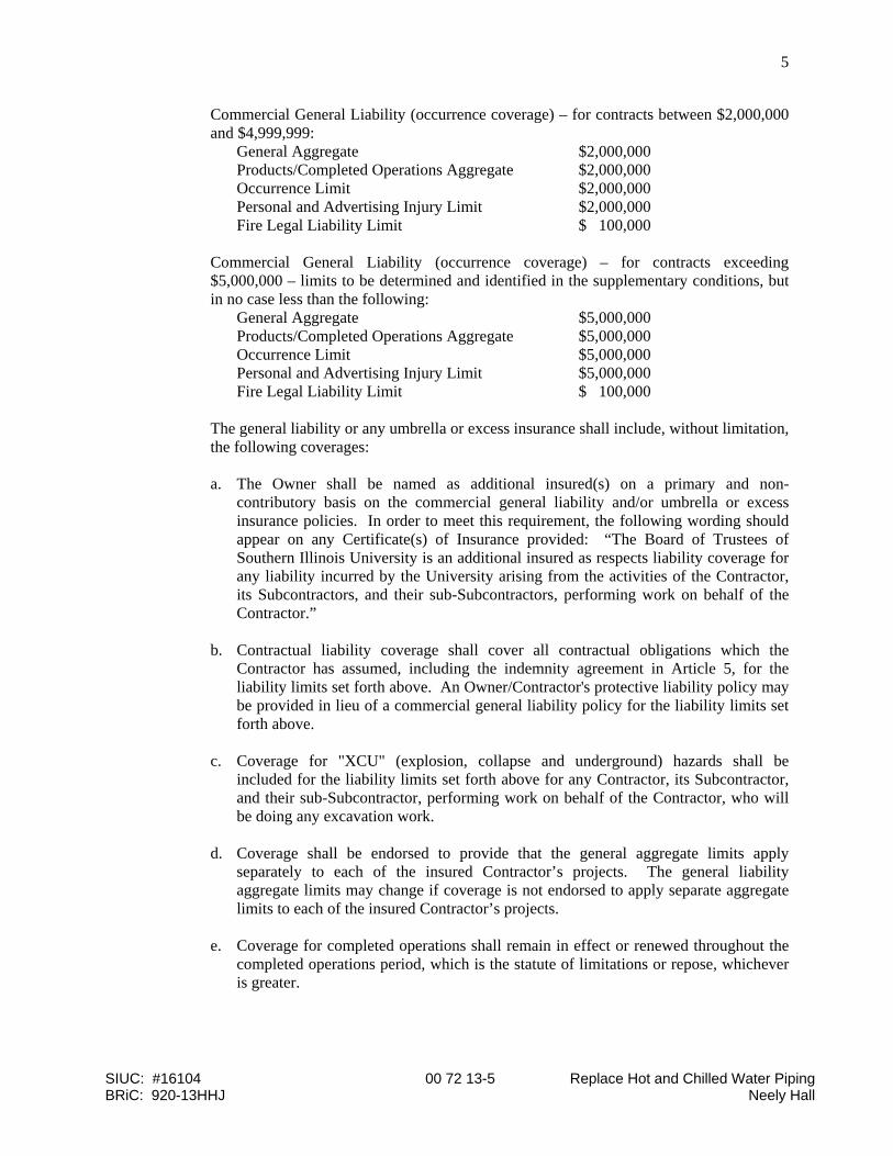
Commercial General Liability (occurrence coverage) – for contracts between $2,000,000 and $4,999,999:
General Aggregate $2,000,000 Products/Completed Operations Aggregate $2,000,000 Occurrence Limit $2,000,000 Personal and Advertising Injury Limit $2,000,000 Fire Legal Liability Limit $ 100,000 Commercial General Liability (occurrence coverage) – for contracts exceeding
$5,000,000 – limits to be determined and identified in the supplementary conditions, but in no case less than the following:
General Aggregate $5,000,000 Products/Completed Operations Aggregate $5,000,000 Occurrence Limit $5,000,000 Personal and Advertising Injury Limit $5,000,000 Fire Legal Liability Limit $ 100,000
The general liability or any umbrella or excess insurance shall include, without limitation, the following coverages: a. The Owner shall be named as additional insured(s) on a primary and non-
contributory basis on the commercial general liability and/or umbrella or excess insurance policies. In order to meet this requirement, the following wording should appear on any Certificate(s) of Insurance provided: “The Board of Trustees of Southern Illinois University is an additional insured as respects liability coverage for any liability incurred by the University arising from the activities of the Contractor, its Subcontractors, and their sub-Subcontractors, performing work on behalf of the Contractor.”
b. Contractual liability coverage shall cover all contractual obligations which the
Contractor has assumed, including the indemnity agreement in Article 5, for the liability limits set forth above. An Owner/Contractor's protective liability policy may be provided in lieu of a commercial general liability policy for the liability limits set forth above.
c. Coverage for "XCU" (explosion, collapse and underground) hazards shall be
included for the liability limits set forth above for any Contractor, its Subcontractor, and their sub-Subcontractor, performing work on behalf of the Contractor, who will be doing any excavation work.
d. Coverage shall be endorsed to provide that the general aggregate limits apply
separately to each of the insured Contractor’s projects. The general liability aggregate limits may change if coverage is not endorsed to apply separate aggregate limits to each of the insured Contractor’s projects.
e. Coverage for completed operations shall remain in effect or renewed throughout the
completed operations period, which is the statute of limitations or repose, whichever is greater.
SIUC: #16104 00 72 13-6 Replace Hot and Chilled Water Piping BRiC: 920-13HHJ Neely Hall
6
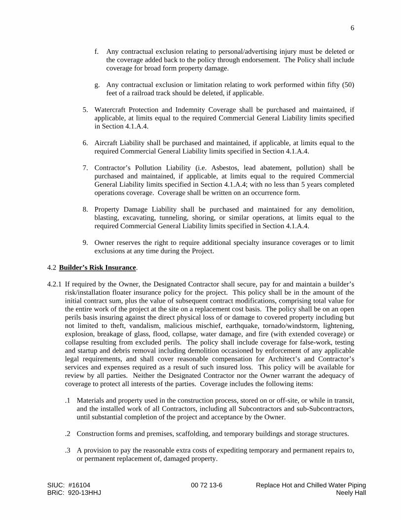
f. Any contractual exclusion relating to personal/advertising injury must be deleted or the coverage added back to the policy through endorsement. The Policy shall include coverage for broad form property damage.
g. Any contractual exclusion or limitation relating to work performed within fifty (50)
feet of a railroad track should be deleted, if applicable. 5. Watercraft Protection and Indemnity Coverage shall be purchased and maintained, if
applicable, at limits equal to the required Commercial General Liability limits specified in Section 4.1.A.4.
6. Aircraft Liability shall be purchased and maintained, if applicable, at limits equal to the
required Commercial General Liability limits specified in Section 4.1.A.4. 7. Contractor’s Pollution Liability (i.e. Asbestos, lead abatement, pollution) shall be
purchased and maintained, if applicable, at limits equal to the required Commercial General Liability limits specified in Section 4.1.A.4; with no less than 5 years completed operations coverage. Coverage shall be written on an occurrence form.
8. Property Damage Liability shall be purchased and maintained for any demolition,
blasting, excavating, tunneling, shoring, or similar operations, at limits equal to the required Commercial General Liability limits specified in Section 4.1.A.4.
9. Owner reserves the right to require additional specialty insurance coverages or to limit
exclusions at any time during the Project.
4.2 Builder’s Risk Insurance. 4.2.1 If required by the Owner, the Designated Contractor shall secure, pay for and maintain a builder’s
risk/installation floater insurance policy for the project. This policy shall be in the amount of the initial contract sum, plus the value of subsequent contract modifications, comprising total value for the entire work of the project at the site on a replacement cost basis. The policy shall be on an open perils basis insuring against the direct physical loss of or damage to covered property including but not limited to theft, vandalism, malicious mischief, earthquake, tornado/windstorm, lightening, explosion, breakage of glass, flood, collapse, water damage, and fire (with extended coverage) or collapse resulting from excluded perils. The policy shall include coverage for false-work, testing and startup and debris removal including demolition occasioned by enforcement of any applicable legal requirements, and shall cover reasonable compensation for Architect’s and Contractor’s services and expenses required as a result of such insured loss. This policy will be available for review by all parties. Neither the Designated Contractor nor the Owner warrant the adequacy of coverage to protect all interests of the parties. Coverage includes the following items: .1 Materials and property used in the construction process, stored on or off-site, or while in transit,
and the installed work of all Contractors, including all Subcontractors and sub-Subcontractors, until substantial completion of the project and acceptance by the Owner.
.2 Construction forms and premises, scaffolding, and temporary buildings and storage structures. .3 A provision to pay the reasonable extra costs of expediting temporary and permanent repairs to,
or permanent replacement of, damaged property.
SIUC: #16104 00 72 13-7 Replace Hot and Chilled Water Piping BRiC: 920-13HHJ Neely Hall
7
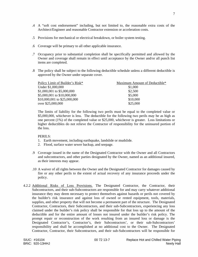
.4 A “soft cost endorsement” including, but not limited to, the reasonable extra costs of the Architect/Engineer and reasonable Contractor extension or acceleration costs.
.5 Provisions for mechanical or electrical breakdown, or boiler system testing. .6 Coverage will be primary to all other applicable insurance. .7 Occupancy prior to substantial completion shall be specifically permitted and allowed by the
Owner and coverage shall remain in effect until acceptance by the Owner and/or all punch list items are completed.
.8 The policy shall be subject to the following deductible schedule unless a different deductible is
approved by the Owner under separate cover. Policy Limit of Builder’s Risk* Maximum Amount of Deductible* Under $1,000,000 $1,000 $1,000,001 to $5,000,000 $2,500 $5,000,001 to $10,000,000 $5,000 $10,000,001 to $25,000,000 $10,000 over $25,000,000 $25,000 The limits of liability for the following two perils must be equal to the completed value or
$5,000,000, whichever is less. The deductible for the following two perils may be as high as one percent (1%) of the completed value or $25,000, whichever is greater. Loss limitations or higher deductibles do not relieve the Contractor of responsibility for the uninsured portion of the loss.
PERILS: 1. Earth movement, including earthquake, landslide or mudslide. 2. Flood, surface water sewer backup, and seepage. .9 Coverage issued in the name of the Designated Contractor with the Owner and all Contractors
and subcontractors, and other parties designated by the Owner, named as an additional insured, as their interests may appear.
.10 A waiver of all rights between the Owner and the Designated Contractor for damages caused by
fire or any other perils to the extent of actual recovery of any insurance proceeds under the policy.
4.2.2 Additional Risks of Loss Provisions. The Designated Contractor, the Contractor, their
Subcontractors, and their sub-Subcontractors are responsible for and may carry whatever additional insurance they may deem necessary to protect themselves against hazards or perils not covered by the builder's risk insurance and against loss of owned or rented equipment, tools, materials, supplies, and other property that will not become a permanent part of the structure. The Designated Contractor, Contractors, their Subcontractors, and their sub-Subcontractors, experiencing any loss claimed under the builder’s risk policy shall be responsible for that loss up to the amount of the deductible and for the entire amount of losses not insured under the builder’s risk policy. The prompt repair or reconstruction of the work resulting from an insured loss or damage is the Designated Contractor’s, Contractor’s, their Subcontractors’, or their sub-Subcontractors’ responsibility and shall be accomplished at no additional cost to the Owner. The Designated Contractor, Contractor, their Subcontractors, and their sub-Subcontractors will be responsible for
SIUC: #16104 00 72 13-8 Replace Hot and Chilled Water Piping BRiC: 920-13HHJ Neely Hall
8
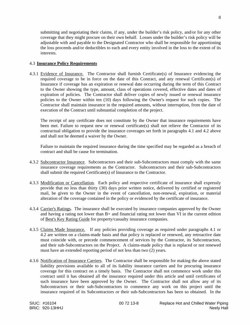
submitting and negotiating their claims, if any, under the builder’s risk policy, and/or for any other coverage that they might procure on their own behalf. Losses under the builder’s risk policy will be adjustable with and payable to the Designated Contractor who shall be responsible for apportioning the loss proceeds and/or deductibles to each and every entity involved in the loss to the extent of its interests.
4.3 Insurance Policy Requirements 4.3.1 Evidence of Insurance. The Contractor shall furnish Certificate(s) of Insurance evidencing the
required coverage to be in force on the date of this Contract, and any renewal Certificate(s) of Insurance if coverage has an expiration or renewal date occurring during the term of this Contract to the Owner showing the type, amount, class of operations covered, effective dates and dates of expiration of policies. The Contractor shall deliver copies of newly issued or renewal insurance policies to the Owner within ten (10) days following the Owner's request for such copies. The Contractor shall maintain insurance in the required amounts, without interruption, from the date of execution of the Contract until substantial completion of the project.
The receipt of any certificate does not constitute by the Owner that insurance requirements have
been met. Failure to request new or renewal certificate(s) shall not relieve the Contractor of its contractual obligation to provide the insurance coverages set forth in paragraphs 4.1 and 4.2 above and shall not be deemed a waiver by the Owner.
Failure to maintain the required insurance during the time specified may be regarded as a breach of
contract and shall be cause for termination. 4.3.2 Subcontractor Insurance. Subcontractors and their sub-Subcontractors must comply with the same
insurance coverage requirements as the Contractor. Subcontractors and their sub-Subcontractors shall submit the required Certificate(s) of Insurance to the Contractor.
4.3.3 Modification or Cancellation. Each policy and respective certificate of insurance shall expressly
provide that no less than thirty (30) days prior written notice, delivered by certified or registered mail, be given to the Owner in the event of cancellation, non-renewal, expiration, or material alteration of the coverage contained in the policy or evidenced by the certificate of insurance.
4.3.4 Carrier's Ratings. The insurance shall be executed by insurance companies approved by the Owner
and having a rating not lower than B+ and financial rating not lower than VI in the current edition of Best's Key Rating Guide for property/casualty insurance companies.
4.3.5 Claims Made Insurance. If any policies providing coverage as required under paragraphs 4.1 or
4.2 are written on a claims-made basis and that policy is replaced or renewed, any retroactive date must coincide with, or precede commencement of services by the Contractor, its Subcontractors, and their sub-Subcontractors on the Project. A claims-made policy that is replaced or not renewed must have an extended reporting period of not less than two (2) years.
4.3.6 Notification of Insurance Carriers. The Contractor shall be responsible for making the above stated
liability provisions available to all of its liability insurance carriers and for procuring insurance coverage for this contract on a timely basis. The Contractor shall not commence work under this contract until it has obtained all the insurance required under this article and until certificates of such insurance have been approved by the Owner. The Contractor shall not allow any of its Subcontractors or their sub-Subcontractors to commence any work on this project until the insurance required of its Subcontractors or their sub-Subcontractors has been so obtained. In the
SIUC: #16104 00 72 13-9 Replace Hot and Chilled Water Piping BRiC: 920-13HHJ Neely Hall
9
event of any incident, injury, death, or loss or damage (or claims thereof), the Contractor shall give immediate notice thereof to the Owner and their insurance carrier(s).
4.3.7 Contractor's Liability. The procuring of the insurance required under this contract shall be
considered solely as securing Contractor's obligations or liabilities assumed under the contract documents, including, but not limited to, the obligation to indemnify the Owner assumed under Article 5 and shall not be considered as satisfaction of, or a substitution for, such obligations and liabilities. The Contractor shall remain liable and responsible for all such obligations whether or not the insurance provided by it is approved by the Owner and whether or not such insurance is sufficient in amount, quality or coverage to protect it against such liability. The Contractor shall pay and make good all such obligations to the full extent thereof and to the extent that such insurance does not cover them.
4.3.8 Enforcement of this Contract. In the event Owner retains legal counsel to secure performance by
Contractor, its Subcontractors, and their sub-Subcontractors, of any of their obligations under this contract, or if Owner retains or utilizes such counsel to represent its interest with respect to any matter for which Contractor has an indemnity obligation to Owner under any provision of this contract or otherwise, the Contractor shall pay and reimburse Owner for the cost of such counsel and shall further pay and reimburse Owner for any and all other cost and expense incurred in preparing, negotiating, or prosecuting any claim against the Contractor, its Subcontractors, and their sub-Subcontractors including, but not limited to, any and all expert witness fees and expenses.
4.3.9 Waiver of Subrogation Clause. The Contractor’s insurance policies shall include the following
waiver of subrogation clause:
“It is agreed that in no event shall any insurance company of the Contractor have any right of recovery against the Owner for any and all damage or loss unless such damage or loss results from the sole gross negligence or willful misconduct of the Owner.”
4.4 Waivers of Subrogation The Owner and Contractor waive all rights against each other for damages caused by fire or other
perils to the extent of actual recovery of any insurance proceeds under any property insurance obtained pursuant to Article 4 or other insurance applicable to the work. The Contractor agrees that in no event shall they or their agents have any right of recovery against the Owner for any and all damage or loss unless such damage or loss results from the sole gross negligence or willful misconduct of the Owner.
Each insured Contractor shall require similar waivers of subrogation from its Subcontractors and
their sub-Subcontractors. ARTICLE 5. Indemnification 5.1 Indemnification. The Contractor agrees to pay and reimburse and indemnify, keep and hold harmless
Southern Illinois University (and the Architect/Engineer/Professional Services Consultant, if applicable), their trustees, officials, agents, employees and their respective heirs, executors, administrators, officers, directors, successors and assigns from and against any and all losses, demands, obligations, costs, damages, liabilities, suits, actions, judgments, claims (including, but not limited to, claims for the infringement of any patents, copyrights, licenses or other intellectual property rights) and expenses, including, but not limited to, attorneys’, consultants’, and experts’ fees
SIUC: #16104 00 72 13-10 Replace Hot and Chilled Water Piping BRiC: 920-13HHJ Neely Hall
10
and expenses, and including both litigation and pre-litigation expenses, arising out of or connected with: (a) any injury to or death of persons or damage to or loss or destruction of property caused by or attributable to negligent or willful acts or errors or omissions, in whole or part, of the Contractor, its Subcontractors, and their sub-Subcontractors and their respective officers, agents, representatives, or employees; (b) any act, error, or omission arising from the gross professional negligence of the Contractor, its Subcontractors, and their sub-Subcontractors and their respective officers, agents, representatives, or employees relating to the performance of services in connection with the Project; (c) any breach or failure of performance by the Contractor, its Subcontractors, and their sub-Subcontractors and their respective officers, agents, representatives, or employees under this Agreement. The provisions of this paragraph are applicable to the full extent allowed by the laws of the State of Illinois and not beyond any extent which would render them void or unenforceable. In the event of any such injury, death, or loss or damage (or claims thereof), the Contractor shall give immediate notice thereof to the Owner.
5.2 Insurance Certification. The Contractor agrees to maintain the insurance coverages required of them
under Article 4 for the duration of the project or the term for which services will be rendered, and for as long as necessary thereafter to cover claims with respect to their performance under this Agreement. The Contractor agrees to require its Subcontractors and their sub-Subcontractors to maintain the insurance coverages required of them under Articles 4 and 5 for the duration of the project or the term for which services will be rendered, and for as long as necessary thereafter to cover claims with respect to its performance under this agreement.
ARTICLE 6. Visiting the Site All bidders should visit the site of the proposed project so that they may fully understand the facilities, difficulties and restrictions attending the execution of the contract. No additional compensation or extension of time for completion will be allowed for failure to be so informed. Bidders shall make a careful check of the drawings and a close comparison of all drawings and existing conditions to ascertain the full amount of work necessary to obtain the results indicated. ARTICLE 7. Substitutions It is the intention of Southern Illinois University Carbondale to purchase high quality material and/or services and evaluation of responses will be made on this basis. All bids shall be based on providing all products exactly as required by the bid documents SIU reserves the right to sole source a supplier, manufacturer or subcontractor. This proprietary source will be clearly identified as the sole source in the project manual. Bidders shall include this item in their base or alternate bids. If the bidder identifies other items that are “de facto” proprietary by the nature of the specifications, the bidder is required to notify SIU immediately upon discovery. It is preferred that requests for substitutions be submitted prior to the bids. Such requests should be received at least ten (10) calendar days prior to the bid opening and a complete description of the desired change including any technical data and references for SIU’s evaluation. SIU will include the modification by addendum if a request is approved. SIU reserves the right to reject any proposed substitution. After notice of award, substitutions may only be approved by written change order under one of the following conditions:
SIUC: #16104 00 72 13-11 Replace Hot and Chilled Water Piping BRiC: 920-13HHJ Neely Hall
11
a) Substitutions are required for compliance with final interpretations of code requirements or insurance regulations;
b) Unavailability of specified products, through no fault of contractor; c) Subsequent information discloses inability of a specified product to perform properly or to fit in
designated space; d) Manufacturer/fabricator refusal to certify or guarantee performance of a specified product as
specified; or e) When a substitution would be substantially in owners best interests
Submittal Requirements: When requested by owner, the contractor shall submit complete data demonstrating compliance of the proposed substitution with contract documents:
a) An itemized comparison of proposed substitution with product or method specified; b) Data relating to changes in construction schedule, coordination, and other affected contracts; c) Accurate cost data on proposed substitution in comparison with product or method specified; and d) Accepted substitutions will be so stated in the contract.
Representation: In making a request for substitution, contractor represents that:
a) The proposed product is equal or superior to that specified; b) It will provide an equal or superior guarantee for the substitution as was specified; c) It will coordinate installation of accepted substitutions into work, making all changes for work to
be complete; and d) It will pay all additional costs and expenses for SIU, A/E, and other contractors affected.
Restriction: Substitutions will not be considered by shop drawing, informal request or when acceptance will require substantial revision of contract documents. Specifications: Any reference to brand names and numbers in the solicitation is descriptive, but not restrictive, unless otherwise specified. Offers on equivalent items meeting the standards of quality thereby indicated will be considered, unless, otherwise specified, providing the offer clearly describes the article offered and how it differs from the referenced brands. Unless the respondent specified otherwise, it is understood that the respondent is offering a referenced brand item as specified in the solicitation. The University will determine whether a substitute offer is equivalent to and meets the standards of quality indicated by the brand name referenced; and the University may require a respondent offering a substitute to supply additional descriptive material and a sample. If items requested have quality guidelines of brand name or equal, the items offered must be equal to or better than the brands and model numbers specified as determined by Southern Illinois University Carbondale. The use of brand names in this solicitation are for the purpose of describing the standard of quality performance and characteristics desired and is not intended to limit or restrict competition. Substantially equivalent products to those designated may be considered for award. “Or Equal” submissions will not be rejected because of minor differences in design, construction, or features that do not affect the suitability of the product for its intended use. Samples: If requested, samples of items must be furnished free of charge and if not destroyed will, upon request, be returned at the respondents’ expense. Request for the return of samples must be made within ten (10) days following opening of Bid or RFP or submittal of samples, whichever is later. Each individual sample must be labeled with respondents’ name, manufacturer’s brand name and product number, Bid or RFP number, and item referenced. The University reserves the right to keep the samples of the low respondent. Failure to submit samples when requested will be considered grounds for rejection
SIUC: #16104 00 72 13-12 Replace Hot and Chilled Water Piping BRiC: 920-13HHJ Neely Hall
12
of your offer. DO NOT submit samples unless you are specifically requested to do so. Samples should arrive within 7 working days from receipt of request. ARTICLE 8. Acceptance or Rejection of Proposals The Board of Trustees of Southern Illinois University, and its designees, reserves the right to reject any or all proposals or any part thereof, to waive any informality in the bidding, and to accept the proposal deemed most favorable to the interest of the University. ARTICLE 9. Withdrawal of Proposals
a) Any bidder may withdraw their proposal at any time prior to the scheduled closing time for the receipt of bids. A bidder may withdraw their proposal by letter or telegram, or with proper identification, by personally securing their bid proposal. Telephoned requests to withdraw a bid will not be considered.
b) If a bidder requests a withdrawal of their bid, bidder must establish, clearly and convincingly, that the bid was founded on a credible error or omission. The owner shall review the evidence provided and make a determination. If the owner finds that the evidence of the mistake is not credible, the request will be denied and the bid will stand. The request may be granted if evidence of the mistake is credible. If the bidder requests have been excessive sanctions may be imposed, including default of the bid security. Other sanctions may include denial of bidding privileges, revocation of responsibility determination, or other appropriate actions.
c) By the submission of a bid the bidder certifies and agrees that his/her bid will remain a firm offer
for one-hundred twenty (120) days from the date of opening the bids, and only the owner executing an agreement with another bidder for this work will release the bidder from their (120) day firm commitment. This commitment is made in consideration of the University considering the bid submitted.
Cancellation for Cause: Any purchase agreement or contract arising from this solicitation will be subject to cancellation by Southern Illinois University Carbondale upon written notice and without penalty to Southern Illinois University Carbondale if, in the opinion of Southern Illinois University Carbondale, the quality, delivery schedule, specifications, terms or conditions, and other service requirements are not maintained as originally stated and accepted by the vendor. Multiple Year Contracts: If the initial term of the contract spans multiple fiscal years (July 1 through June 30) the following funding clause is applicable. Any purchase agreement or contract arising from this solicitation is subject to termination and cancellation in any year for which the General Assembly fails to make an appropriation to make payments under the terms of the purchase agreement contract. ARTICLE 10. Taxes Sales to the University, unless otherwise stated, are exempt from Illinois R.O.T. and Federal Taxes. Southern Illinois University Carbondale’s tax exempt number is E9990-8433-06. The University is an instrumentality of the State of Illinois, and as such it is exempt from Federal Income Tax under Sections 115 and 501(c)(3) of the Internal Revenue Code and is exempt from State of Illinois Income Tax in accordance with the Illinois Income Tax Act (35 ILCS 5/205). However, the University is subject to Federal and State of Illinois Income Tax only if, and to the extent, it has unrelated business taxable income. In addition, the University is exempt from payment of state and local Retailers’

SIUC: #16104 00 72 13-13 Replace Hot and Chilled Water Piping BRiC: 920-13HHJ Neely Hall
13
Occupation Tax, state and local Service Occupation Tax, state Use Tax, and state Service Use Tax, as provided by Illinois law. Certificates of exemption will be provided upon written request. Contractors may utilize Tax Exemption Letter for Southern Illinois University Carbondale, http://www.procurement.SIU.edu/taxexempt.html ARTICLE 11. Labor In the performance of all contracts with the University, contractors and subcontractors must conform to requirements regarding labor, including, but not necessarily limited to, the following: PROJECT LABOR AGREEMENT Provides for a signed agreement between all project contractor(s) and the Egyptian Building and Construction Trades Council for and on behalf of its affiliates for the duration of the specified project. FINANCE (30 ILCS 570/) Employment of Illinois Workers on Public Works Act. Provides in part, that whenever there is a period of excessive unemployment in Illinois, Illinois laborers shall constitute a minimum of 90% of the work-force on any public works project. VETERANS (330 ILCS 55/) Veterans Preference Act. Gives preference to veterans of the United States Military and Naval Service (who are residents in the district) in appointments and employment upon public works projects. Preference is only required for veterans who are found to possess the business capacity necessary for the proper discharge of the duties of such employment. EMPLOYMENT (820 ILCS 130/) Prevailing Wage Act. Provides in part, that contractors, subcontractors etc., shall pay to all laborers, workers, and mechanics engaged in the construction of public works, under this contract, not less than the prevailing rate of wages for work of a similar character in the locality of the project. HUMAN RIGHTS (775 ILCS 5/) Illinois Human Rights Act and (775 ILCS 10/) Public Works Employment Discrimination Act. Prohibits discrimination and intimidation because of race, creed, color, sex, religion, age, national origin, physical or mental handicap unrelated to ability in employment under contracts for public buildings or public works. All contractors (and subs) will further be required to comply with all Illinois and Federal executive orders as applicable, including but not limited to those orders requiring non-discrimination in employment, and the owner’s Affirmative Action Program. ARTICLE 12. Rates of Wages for Workers The minimum wages to be paid laborers, mechanics, and others on this project are those prevailing for the corresponding classes of laborers and mechanics employed on projects of a character similar to the contract work in the locality as certified by the Director of Labor, State of Illinois.
SIUC: #16104 00 72 13-14 Replace Hot and Chilled Water Piping BRiC: 920-13HHJ Neely Hall
14
The rates are minimum rates only, and the owner will not consider any claims for additional compensation made by the contractor because of payment by the contractor of any wage rate in excess of the applicable wage rates contained in the contract. If, after the award of the contract, it becomes necessary to employ any person in a trade or occupation not classified in the above-mentioned certified list, such person shall be paid not less than such rate as shall be determined by the owner and approved by the Director of Labor, State of Illinois; and such approved minimum rate shall be retroactive to the time of the initial employment of such person in such trade or occupation. The contractor shall notify the owner of his intention to employ persons in trades or occupations not classified in sufficient time for the owner to obtain approved rates for such trades or occupations. The prospective bidders should investigate existing labor conditions and any negotiated labor agreements, which may exist, or are contemplated at this time. The bidders should verify that the wages are correct, as they will be held to pay the wage rates existing at the time of execution of the contract. An increase in the prevailing wage rates, which may be negotiated and approved after the contract has been signed, shall be absorbed by the contractor, and no additional compensation will be allowed to the contractor for any such increase in wage rates, which may be approved. The minimum wage rates for apprentices will apply only to persons working with the tools of the trade they are learning under the direct supervision of journeymen mechanics. Except as otherwise required by law, the number of apprentices, in each trade or occupation, not exceed the maximum number permitted by the applicable standards of the United States Department of Labor, or, in the absence of such standards, the number permitted under the usual practice prevailing between the unions and the employer's association of the respective trades or occupations. ARTICLE 13. Nondiscrimination of Employment and Equal Employment Opportunity Clause In the event of the contractor’s non-compliance with the provisions of this Equal Employment Opportunity Clause, the Illinois Human Rights Act or the Applicable Rules and Regulations of the Illinois Department of Human Rights (“Department”), the contractor may be declared ineligible for future contracts or subcontracts with the State of Illinois or any of its political subdivisions or municipal corporations, and the contract may be cancelled or voided in whole or part, and such other sanctions or penalties may be imposed or remedies invoked as provided by statute or regulation. During the performance of this contract, the contractor agrees as follows:
a) That it will not discriminate against any employee or applicant for employment because of race, color, religion, sex, marital status, sexual orientation, national origin or ancestry, age, physical or mental handicap unrelated to ability, or an unfavorable discharge from military service; and further that it will examine all job classifications to determine if minority persons or women are underutilized and will take appropriate affirmative action to rectify any such underutilization.
b) That, if it hires additional employees in order to perform this contract or any portion hereof, it
will determine the availability (in accordance with the Department’s Rules and Regulations) of minorities and women in the area(s) from which it may reasonably recruit and it will hire for each job classification for which employees are hired in such a way that minorities and women are not underutilized.
c) That, in all solicitations or advertisements for employees placed by it or on its behalf, it will state
that all applicants will be afforded equal opportunity without discrimination because of race,
SIUC: #16104 00 72 13-15 Replace Hot and Chilled Water Piping BRiC: 920-13HHJ Neely Hall
15
color religion, sex, marital status, sexual orientation, national origin or ancestry, age, physical or mental handicap unrelated to ability, or an unfavorable discharge from military service.
d) That it will send to each labor organization or representative of workers with which it has or is
bound by a collective bargaining or other agreement or understanding, a notice advising such labor organization or representative of the contractor’s obligations under the Illinois Human Rights Act and the Department’s Rules and Regulations. If any such labor organization or representative fails or refuses to cooperate with the contractor in its efforts to comply with such Act and Rules and Regulations, the contractor will promptly so notify the Department and the contracting agency and will recruit employees from other sources when necessary to fulfill its obligations thereunder.
e) That it will submit reports as required by the Department’s Rules and Regulations, furnish all
relevant information as may from time to time be requested by the Department or the contracting agency, and in all respects comply with the Illinois Human Rights Act and the Department’s Rules and Regulations
f) That it will permit access to all relevant books, records, accounts and work sites by personnel of
the contracting agency and the Department for purposes of investigation to ascertain compliance with the Illinois Human Rights Act and the Department’s Rules and Regulations.
g) That it will include verbatim or by reference the provisions of this clause in every subcontract it
awards under which any portions of the contract obligations are undertaken or assumed, so that such provisions will be binding upon such subcontractor. In the same manner as with other provisions of this contract, the contractor will be liable for compliance with applicable provisions of this clause by such subcontractors; and further it will promptly notify the contracting agency and the Department in the event any subcontractor fails or refuses to comply therewith. In addition, the contractor will not utilize any subcontractor declared by the Illinois Human Rights Commission to be ineligible for contracts or subcontracts with the State of Illinois or any of its political subdivisions or municipal corporations. (Re: Public Contracts; most recent version)
h) The Executive Director of Finance ("office") is the duly authorized agent of the owner to monitor
the equal employment opportunity provisions of the contract. When requested by this office the contractor will supply all information necessary for that office to determine the contractor's compliance or noncompliance with the Owner's Statement and Policy of Equal Employment Opportunity. Compliance with the appropriate federal, state and University equal employment opportunity provisions shall be determined by that office after they have compared the contractor's employment posture and policies with:
1. The minority and female population of the Carbondale area. 2. The size of minority and female unemployment force in the Carbondale area. 3. The percentage of minority and female work forces as compared with the total work force
in the Carbondale area. 4. The general availability of minorities and females having requisite and potential requisite
skills in the Carbondale area. 5. The anticipated expansion, contraction, and turnover of and in the work force. 6. The existence of training institutions capable of training minorities and females in the
requisite skills. The information, derived from the Illinois State Employment Service and the University Affirmative Action / Equal Opportunity Office, shall provide the basis for criteria to assist the
SIUC: #16104 00 72 13-16 Replace Hot and Chilled Water Piping BRiC: 920-13HHJ Neely Hall
16
University Affirmative Action / Equal Opportunity Office in determining compliance or noncompliance with the University affirmative equal opportunity commitments.
i) The contractor will include the provisions of paragraphs (a) through (h) in every subcontract or
purchase order for over $10,000 unless exempted by rules, regulations, or orders of the Secretary of Labor issued pursuant to Section 204 of Executive Order No. 11246 of September 24, 1965, as amended. Sec. 503 of the Rehabilitation Act of 1973, and Sec. 402 of the Vietnam Era Veterans Act, so that such provisions will be binding upon each subcontractor or vendor. The contractor will take such action with a means of enforcing such provisions, including sanctions for noncompliance provided however, that in the event the contractor or vendor is sued as a result of such direction by the contracting agency, the contractor may request the United States to enter into such litigation to protect the interest of the United States.
ARTICLE 14. Illinois Human Rights Act All contractors shall comply with the Illinois Human Rights Act (775 ILCS 5/101, et.seq.) and the Rules and Regulations of the Department of Human Rights applicable to Public Contractors and Sub-Contractors. No person shall be eligible to be awarded a Contract subject to the competitive bidding requirements of the Illinois Procurement Code unless such person, prior to bid opening, has filed with the Illinois Department of Human Rights, 100 West Randolph, Room 10-100, Chicago, Illinois 60601, a properly completed and sworn Employer Report Form (Form PC-1) which is currently valid. In the event of the contractor's noncompliance with any provision of this Equal Employment Opportunity Clause, the Illinois Department of Human Rights Rules and Regulations for Public Contracts, the contractor may be declared non-responsive and therefore ineligible for future contracts or subcontracts with the State of Illinois or any of its political subdivisions or municipal corporations, and the Contract may be cancelled or voided in whole or in part, and such other sanctions or penalties may be imposed or remedies invoked as provided by statute or regulation. ARTICLE 15. Foreign Corporations Foreign Corporations are responsible for obtaining A CERTIFICATE OF AUTHORITY to transact business in the State of Illinois. A Foreign Corporation is a corporation organized under the laws of the state or country other than Illinois. Contact: Secretary of State Office, 217-782-6961. ARTICLE 16. Royalties and Patents
a) The contractor shall save and hold harmless the owner and his officers, agents, servants and employees for, or on account of any patented or unpatented invention process, article, or appliance manufactured or used in the performance of the contract, including its use by the owner, unless otherwise specifically stipulated in the contract documents.
b) If the contractor uses any design, device or material covered by letters of patent or copyright, he/she shall provide for such use by suitable agreement with the owner of such patented or copyrighted process, design, device, or material. It is mutually agreed and understood that, without exception, the contract prices shall include all royalties or costs arising from the use of such process, design, device, or material, if any are involved in the work. The contractor or his/her sureties or both shall indemnify and save harmless the owner of the project from any and all claims or infringement by reason of the use of such patented or copyrights process, design, device, or material, or any trademark in connection with work agreed to be performed under this

SIUC: #16104 00 72 13-17 Replace Hot and Chilled Water Piping BRiC: 920-13HHJ Neely Hall
17
contract and shall indemnify the owner for any and all costs, expenses, or damages, including reasonable attorneys' fees, which he/she may incur or be obliged to pay by reason of such infringement at any time during the prosecution of the work or after completion of the work. This clause shall survive completion of the contract.
ARTICLE 17. Permits and Regulations Each contractor shall obtain and pay for all permits, licenses, and inspections necessary for his work, and shall give all notices, pay all fees, and comply with all laws, ordinances, rules, and regulations bearing on the conduct of the work. In general, work shall be done in accordance with applicable provisions of the National Electric Code, State of Illinois Plumbing Code and the ICC Code, latest editions. ARTICLE 18. Time of Commencement and Time of Completion
a) The contractors shall commence the work under his/her contract within ten (10) consecutive calendar days after the issuance date of written Notice to Proceed and shall fully complete all work thereunder within the time frame stipulated in the contract documents.
b) All other contractors or subcontractors performing work under their contracts at the same time that the coordinating/assigned contractor is doing work are obligated to commence, carry on, coordinate, and complete their work in the various stages so that the entire job will be accomplished on a schedule that will enable the coordinating/assigned contractor to complete his/her work within the required time frame set forth in the contract documents.
c) Copies of a written Notice to Proceed or Purchase Order shall also be forwarded at the same time to all contractors for projects awarded.
d) The coordinating/assigned contractor shall prepare a construction schedule with input and concurrence of all other contractors and shall submit to the University for review and acceptance within 30 consecutive calendar days after the issuance date of written Notice to Proceed. Contractors must provide to the University, if so requested, a manpower utilization summary to support the contractor’s scheduled work timelines. These summaries shall indicate number of work crews, the size of each work crew and the craft title of each work crewmember.
e) The project schedule shall be the contractor’s working schedule and used to execute the work, record and report actual progress.
f) The schedule shall be updated monthly and include actual dates of completed tasks. ARTICLE 19. List of Subcontractors Any contract or purchase order, with an annual total of $50,000 or more, arising from this solicitation shall not be assigned or sublet in whole or in part without the written consent of Southern Illinois University Carbondale. Each prime contractor is requested in this solicitation to submit a list of subcontractors who are being retained by them to perform work under their contract and shall itemize their work for labor and material. This list should contain the names of all (tier 1) subcontractors and major suppliers proposed for the principal parts of their work and for such others as the Engineer and/or Owner may direct and shall not employ any that are not acceptable as provided below. Following award, the prime contractor must supply a copy of the subcontractor contract, the subcontractor completed contract certification form, and financial disclosure form. The bidder is specifically advised that any person, firm, or the party to whom it is proposed to award a subcontract under this contract must be acceptable to the Owner, and must also submit from each proposed subcontractor a certificate of insurance and Project Labor Agreement, if applicable.
SIUC: #16104 00 72 13-18 Replace Hot and Chilled Water Piping BRiC: 920-13HHJ Neely Hall
18
The term "Subcontract" means any agreement, arrangement or understanding, written or otherwise, between a contractor and any person (in which the parties do not stand in the relationship or an employer and an employee) for the furnishing of supplies or services or for the use of real or personal property, including lease arrangements, which, in whole or in part, is utilized in the performance of any one or more contracts. The term “Tier 1” means any subcontractor the prime holds a direct contract with including suppliers. ARTICLE 20. Intent of Documents
a) Contract documents including all addenda are complementary, and what is called for by one trade shall be as binding as if called for by all trades. The intent of the documents is to include all labor, materials, equipment, and whatever else is reasonably necessary for the proper execution of the work. It is not intended, however, that materials or work not covered by, or properly inferable from a heading, section, division, branch, class, or trade of the specifications shall be supplied, unless distinctly so noted on the drawings or required elsewhere in the contract documents. Materials or work described in words, which so applied have a well-known technical or trade meaning shall be held to refer to such recognized standards.
b) In the event that the drawings call for some work not covered by the specifications, the work called for in the drawings shall be included in the work under the contract.
c) In the event that the specifications call for some work not covered by the drawings, the work called for in the specifications shall be included in the contract.
d) In the case of inconsistency between drawings and specifications or within either document itself, the cost of the better quality or greater quantity of work shall be included in the proposal, and the matter drawn to the attention of the Director of Procurement Services for decision and/or adjustment.
e) The organization of the specifications into divisions, sections, and articles and the arrangement of drawings shall not control the contractor in dividing the work among subcontractors or in establishing the extent of work to be performed by any trade.
f) Each and every provision of law and clause required by law to be inserted in this contract shall be deemed to be inserted herein and the contract shall be read and enforced as though it were included herein. Nothing stated in or omitted from the contract documents shall be construed as relieving the contractor from his/her obligations to comply with all state and federal laws, rules and regulations.
g) All applicable Federal and State laws, municipal ordinances, and the rules and regulations of all authorities having jurisdiction over construction of the project shall apply to the project throughout, and they will be deemed to be included in the bid documents and contract the same as though herein written out in full.
ARTICLE 21. Shop Drawings No part of the work requiring a shop drawing or sample shall be started until the submission has been approved by Southern Illinois University Carbondale Physical Plant Engineering. Contractor’s responsibility for errors, omissions or deviation from contract documents in submittals is not relieved by the University’s review of submittals. Then all work shall be in accordance with these approved shop drawings. Any impact to the construction schedule due to shop drawings requiring resubmittal, whether being deemed as non-acceptable or requiring additional information, shall be the sole responsibility of the contractor, to make up any deviations or slippages.

SIUC: #16104 00 72 13-19 Replace Hot and Chilled Water Piping BRiC: 920-13HHJ Neely Hall
19
ARTICLE 22. Materials, Appliances, Employees
a) It is understood that, except as otherwise specifically stated in the contract documents, the contractor shall provide and pay for all materials, labor, tools, equipment, water, light, power, transportations, superintendence, temporary construction of every nature, and all other services and facilities of every nature whatsoever necessary to execute, complete, and deliver the work within the specified time. Unless otherwise specified, all materials shall be new, and both workmanship and materials shall be of the best quality. Contractor shall, if required by the owner, furnish satisfactory evidence as to the kind and quality of materials.
b) The contractor shall provide and erect all necessary scaffolding, hoists, derricks, guard- rails, safety devices, special tools, or machinery necessary for the completion of the projects, and shall properly maintain same during the construction period.
c) All material, equipment, appliances, devices, and the manner in which they are used or installed shall comply with the requirements of OSHA. This includes not only the items used in the course of construction but also all items, which are part of the contract and become a permanent part of the project.
d) The contractor shall enforce strict discipline and good order among his/her employees and shall discharge from the project to which these conditions apply, upon receipt of written notice, any person found by the owner to be unfit and unskilled.
ARTICLE 23. Protection of Work and Property
a) Precaution shall be exercised at all times for the protection of persons (including students and employees) and property.
b) Each contractor shall continuously maintain adequate protection for all his work from damage of any type whatsoever, and shall protect the owner’s property from injury arising in connection with the work under this contract. He shall make good any damage or injury, except such as may be directly due to errors in the contract documents. He shall adequately protect adjacent property and shall procure and maintain insurance for this purpose.
c) Walks, curbs, roadways, utilities, etc., damaged during the progress of the work shall have damaged work removed and replaced with new similar materials by the contractor causing such damage, leaving all walks, curbs, roadways, utilities, etc., in good condition as approved by the agency having jurisdiction over the damaged route.
d) The prime contractors shall be responsible for removal of all excavated material, debris, rock, sand, gravel, and the like spilled on these walks, streets, or roads, and for the maintenance of these walks, streets, and roads in a clean and good condition.
e) The contractor shall protect all work and unused materials of his/her contract from freezing or inclement weather, and shall be solely responsible for the condition of such work and materials.
ARTICLE 24. Working Regulations
a) Contractors engaged in construction, reconstruction, repair or demolition work within the grounds or areas governed by Southern Illinois University Carbondale should conform to the rules and regulations in force at the University.
b) Contractors shall enforce the owner’s instructions regarding signs, advertisements, fires, and smoking. No alcoholic beverage shall be consumed, possessed or allowed on University property.
c) Before commencing work contractors shall confer with the owner and ascertain full knowledge of all local rules and regulations affecting his working conditions.
SIUC: #16104 00 72 13-20 Replace Hot and Chilled Water Piping BRiC: 920-13HHJ Neely Hall
20
d) Working rules and regulations in force within the grounds at Southern Illinois University Carbondale shall take precedence within the area over all other rules and regulations, which may exist outside of this jurisdiction.
ARTICLE 25. Use of Site
a) The contractor shall confine its operations at site to areas permitted by law, permits, contract and University’s permission. The contractor and its employees shall keep all unattended vehicles and equipment locked at all times and parked only in approved areas. Violators will be ticketed and responsible for paying all assessed fines.
b) The contractor shall assume responsibility for protection and safekeeping of its materials, equipment, tools, etc. stored on the premises. Contractor shall obtain and pay for use of any additional storage or work area needed for its operations. Contractor shall move all stored material, equipment, tools, etc., which interfere with the work. University shall not be responsible for any theft or damage to the contractors’ material, equipment, tools, etc.
c) The contractor shall provide and maintain appropriate fences, barricades and/or security locks to limit resident access to excavations, construction areas, construction field offices and storage structures.
d) Contractor shall not burn debris and waste on site. Open flame heaters shall not be used without the written approval of the University, and then only when maintained under constant supervision.
ARTICLE 26. Protection of Trees, Shrubs, and Planting The trees and shrubs to be left standing shall be completely protected from damage incident to construction operations by the erection of solid timber barriers or other means as approved. Such protection shall be erected at the start of work, shall be maintained undisturbed except for augmentation or repair until completion of work, and then shall be removed as directed. If any tree or shrub, which is to be left standing, is damaged in the performance of construction activities, it shall be repaired or replaced as directed. If any such tree or shrub is destroyed by such activities, it shall be replaced. Replacement of any tree or shrub shall be with one of like size and variety in satisfactory growth. The foregoing specifically shall include damage to trees or shrubs by soil compaction or from other cause brought on by storage of materials on the ground over the root system. Grass and other planting areas to remain, which are disturbed by operations under this contract shall be restored to their original condition or as directed. ARTICLE 27. Cleaning up Each contractor shall at all times keep the premises free from accumulation of waste materials or rubbish caused by his/her operations. Remove debris and rubbish from pipe chases, plenums, attics, crawlspaces and other closed spaces, prior to closing the space. Each contractor shall provide covered containers for deposit of waste and rubbish and shall arrange for regular disposal of construction waste. At the completion of the work he/she shall remove all his/her waste materials and rubbish from and about the project as well as all his/her tools, construction equipment, machinery, and surplus materials, and shall clean all glass surfaces and leave the work “broom clean” or its equivalent, except as otherwise specified. Contractor shall be responsible for maintaining compliance with applicable local, state and/or federal guidelines (e.g., OSHA, EPA, etc.) during any sandblasting activity and during clean up and removal of all resulting debris to an approved off-campus location.
SIUC: #16104 00 72 13-21 Replace Hot and Chilled Water Piping BRiC: 920-13HHJ Neely Hall
21
ARTICLE 28. Damages Should any contractor, their agents, their workers, or any of their subcontractors or materials cause damage to the owner, their property, or other persons, the damage shall be the sole responsibility of such contractor and he/she shall procure and maintain insurance for this purpose. Repairs and replacement of this work under the contract shall be under the direction of the owner or their representatives, and cost of this work shall be the sole responsibility of the contractor causing the damage. ARTICLE 29. Mutual Responsibility of Contractors The contractor shall afford other contractors reasonable opportunity for the introduction and storage of their materials and equipment and the execution of their work, and shall properly connect and coordinate his/her work with theirs. ARTICLE 30. Coordination and Cooperation
a) Each contractor shall coordinate his/her work with every other contractor on the project. All work shall be installed in proper sequence with other trades, without any unnecessary delay in the completion of any other part or parts of the work.
b) Drawings for mechanical and electrical work are generally diagrammatic and indicate the general arrangement of the equipment, the runs of piping and ducts, and the manner of connection. Each contractor shall carefully examine the drawings and shall be responsible for the proper fitting of equipment, fixtures, and piping as indicated, without major alterations. Contractors shall be solely responsible for the proper arrangement of their piping, ducts, and equipment.
c) Each contractor shall confer with all contractors engaged in the construction of the project whose work may in any way affect his/her installation. Whenever interferences might occur, before any work is done at the places in question, each contractor shall consult with other contractors and shall come to an agreement with them as to the exact location and level of his piping, ducts, or other works, to eliminate interference.
d) All overhead ducts, piping, conduit, etc., shall be installed at the maximum possible height. e) Each contractor shall provide openings for its own work unless stated otherwise. The contractor
shall coordinate openings in walls, floors, ceilings, foundations, and slabs on grade or roofs with the other contractors.
ARTICLE 31. Inspection of Work
a) The owner and his/her representatives shall at all times have access to the work whenever it is in preparation or progress, and the contractor shall provide proper facilities for such access and for inspection.
b) If any such work should be covered up without approval or consent of the owner, or his/her representatives, it must, if required by the owner, be uncovered for examination at the contractor’s expense.
ARTICLE 32. Foreman Supervision Each contractor shall keep on his/her work, during its progress, a competent foreman and any necessary assistants, all of who are satisfactory to the owner. The foreman shall represent the contractor in his/her absence, and all directions given to him shall be as binding as if given to the contractor personally. Upon written request, such directions shall be repeated in writing to the contractor.
SIUC: #16104 00 72 13-22 Replace Hot and Chilled Water Piping BRiC: 920-13HHJ Neely Hall
22
ARTICLE 33. Change in the Work The owner, without invalidating the contract, may make changes by altering, adding to, or deducting from the work, the contract sum being adjusted accordingly. Such work shall be executed under the conditions of the original contract, except that any claim for extension of time caused thereby shall be adjusted at the time of ordering such changes. ARTICLE 34. Deductions for Uncorrected Work If the contractor fails to make corrections or repairs to work performed incorrectly or in the alternative, fails to complete the work in accordance with the contract, the difference in value together with a fair allowance for damage shall be deducted from the contract amount due. The owner shall determine the value of such deduction. ARTICLE 35. Owner’s Right to do Work If the contractor neglects to perform or complete the work properly or fails to abide by any provisions of the contract, then upon providing seven (7) calendar days written notice to the contractor, Owner may, without prejudice to any other remedy in equity or law, take any and all necessary action to correct such deficiencies and deduct the cost incurred by Owner for such corrections from all or a portion of payment(s) due to the contractor. ARTICLE 36. Assignments Contractor shall not assign the whole or any part of the contract or any monies due or to become due hereunder without written consent of the owner. If the contractor assigns all or any part of any monies due or to become due under this contract, the instrument of assignment shall "state" that the rights of the assignee in and to any monies due or to become due to the contractor shall be subject to prior claims of all persons, firms and corporations for services rendered or materials supplied for the performance of the work called for in the contract. ARTICLE 37. Labor and Wage Record
a) The contractor shall keep an accurate record showing the names, addresses, classifications, per diem wages, hours worked, and amounts paid to each laborer, mechanic, and workman employed on the project or on work directly relating to the project.
b) The contractor shall have such a record kept by each of his/her subcontractors for their employees.
c) These records are to be made available on request, at all reasonable hours, to the inspection of the owner or his/her representatives and to the Director of Labor, State of Illinois, and their deputies and agents.
ARTICLE 38. Application for Payments and Payment to Contractors
a) The contractor shall furnish for approval of the owner, on forms to be supplied by the owner:
1. A detailed summary giving a complete breakdown of the contract price including labor, material and names of subcontractors and suppliers, scheduled to prepare the work.
2. Periodic itemized summaries of work done for the purpose of making partial payments thereon.
SIUC: #16104 00 72 13-23 Replace Hot and Chilled Water Piping BRiC: 920-13HHJ Neely Hall
23
The costs employed in making up any of these schedules will be used only for determining the basis of partial payments and will not be considered as fixing a basis for additions to or deductions from the contract price.
b) The contractor may submit to the owner monthly applications for partial payment. Such applications shall be presented in five (5) copies, each copy accompanied by one or more of the following documents, if required:
1. Affidavit to Accompany Application for Certificate of Payment 2. Materials Inventory for Application for Payment 3. State of Account or Waivers of Lien
Retainage When periodic payments are made, the University shall retain a fixed percentage of 10% to insure faithful completion of the contract. No amount of funds, in addition to those provided for in a contract for repairs, maintenance, remodeling, renovation, or construction, may be obligated or expended unless the additional work to be performed or materials to be furnished are germane to the original contract. Even if germane to the original contract, no additional expenditures or obligations may, in their total combined amount, be in excess of the percentages of the original contract amount as provided in Section 30-35 (b) of the Code unless they have received the prior written approval of an official pre-designated by the University with the appropriate level of authority to make such determination. Notices of additional expenditures or obligations in excess of the small purchase limit of Section 20-20 of the Code shall be published in the next available Higher Education Bulletin. The University will consider a reduction in the retainage held upon request by the contractor after successful completion of a minimum of 50% of the project. ARTICLE 39. Liens
a) Lien waivers are not required with first payment application if less than 50% of the contract amount. Each subsequent payment shall include the contractor’s partial waiver and partial waivers from all subcontractors and suppliers who were included in the immediately preceding payment application and in the amount as reflected on said application.
b) Neither the final payment nor any part of the retained percentages shall become due until the contractor, as required, delivers to the owner a complete release of all liens or rights of lien arising out of this contract or receipts in full in lieu thereof and, if required in either case, an affidavit that to the best of his knowledge or information the releases and receipts include all the labor and material for which a lien could be filed. The contractor may, if any subcontractor refuses to furnish a release or receipt in full, furnish a bond satisfactory to the owner to indemnify him against any such possible lien, including all costs and a reasonable attorney’s fee.
ARTICLE 40. Compliance with "Kick-back Statute" and Regulations Each contractor and each of his subcontractors shall comply with the following statutes (and with regulations issued pursuant thereto, which are incorporated herein by reference):
a) 18 U.S.C.A. § 874 Kickbacks from public works employees: Whoever, by force, intimidation, or threat of procuring dismissal from employment, or by any other manner whatsoever induces any person employed in the construction, prosecution, completion or repair of any public building, public work, or building or work financed in whole or in part by loans or grants from the United States, to give up any part of the compensation to which he is entitled under his contract of employment, shall be fined under this title or imprisoned not more than five years, or both;

SIUC: #16104 00 72 13-24 Replace Hot and Chilled Water Piping BRiC: 920-13HHJ Neely Hall
24
b) 40 U.S.C.A. § 3145 formerly cited as 40 USCA § 276cSection 3145. Regulations governing contractors and subcontractors: (a) In general. --The Secretary of Labor shall prescribe reasonable regulations for contractors and subcontractors engaged in constructing, carrying out, completing, or repairing public buildings, public works, or buildings or works that at least partly are financed by a loan or grant from the Federal Government. The regulations shall include a provision that each contractor and subcontractor each week must furnish a statement on the wages paid each employee during the prior week. (b) Application. -- Section 1001 of title 18 applies to the statements.
ARTICLE 41. Guarantees Prior to final acceptance of work and payment, the contractor shall guarantee and affirm in writing that all material and workmanship is free from defects. He/she shall further agree to repair and replace, at his/her sole cost and expense, any and all defective material and workmanship furnished under this contract that becomes evident within one (1) year from the date of final acceptance by the owner as evidenced by the issuance of final certificate for payment, unless otherwise specified. Repairs and replacements shall include, but not be limited to, all adjacent work not necessarily provided by the contractor but damaged as a result of such defects or non-conforming work or as a result of remedying them. ARTICLE 42. Liquidated Damages If the vendor fails to perform, provides non-conforming or damaged merchandise, or the order is cancelled for cause, the University may be entitled to compensation by reimbursement or by other legal remedy liquidated damages including, but not limited to, the following:
a. The additional cost of services or goods bought elsewhere, b. Cost of repeating the bid or proposal procedure, c. Any expense incurred because of delay in service or delivery, d. Any other damages caused by or antecedent to a breach of contract by the vendor.
ARTICLE 43. Starting of Systems Each contractor shall conduct a thorough and systematic performance test of each element and total system in the presence of the University. Contractor must demonstrate that all systems comply with the requirements of the contract documents and test all control, alarm and specialty systems including boilers, chillers, motor controls, building automation, power distribution, lighting, compressors, standby power and special mechanical systems. Contractor must correct or adjust all deficiencies in operation and retest as directed by the University. ARTICLE 44. Training Each contractor shall provide formal training to all staff, employees and subcontractors in the operation and maintenance of all building systems. Contractor must provide preliminary operation and maintenance manuals to serve as the basis for University training. Upon completion of training, the contractor shall submit in writing to the University records of the type of training, dates when training was presented, duration of each training session, material covered and the names of University personnel in attendance.
SIUC: #16104 00 72 13-25 Replace Hot and Chilled Water Piping BRiC: 920-13HHJ Neely Hall
25
ARTICLE 45. Record Documents Contractor must:
a) Maintain and keep current the contract documents including the drawings, specifications, addenda, approved shop drawings, field test records, schedules, correspondence and other modifications to the contract on file at the site.
b) Record actual construction installations including foundation depths, locations of underground utilities, location of internal utilities concealed in construction, field changes of dimension and detail and changes made by change order or field order.
c) Upon completion of project, the contractor shall turn over to the University a complete set of record documents, including as-built drawings. Submittals shall have a transmittal letter indicating the name and number of each record document.
ARTICLE 46. Steel Products Procurement Act To conform to the Steel Products Procurement Act, 30 ILCS 565, and as amended, it is mandatory wherein "Steel Products" are utilized for the construction, reconstruction, alterations, repair, improvement, or maintenance of public works made by a public agency contain a provision that steel products used or supplied in the performance of the Contract or any subcontract thereto shall be manufactured or produced in the United States. The provisions of this Act shall not apply:
1. Where the Contract involves an expenditure of less than $500. 2. Where the executive head of the public agency certifies in writing that:
a) The specified products are not manufactured or produced in the United States in sufficient quantities to meet the agency's requirements or cannot be manufactured or produced in the United States within the necessary time in sufficient quantities to meet the agency's requirements, or
b) Obtaining the specified products, manufactured or produced in the United States would increase the cost of the Contract by more than 10%.
3. When its application is not in the public interest. No public agency may authorize, provide for, or make any payment to any vendor or Contractor upon any Contract in violation of Section 4 of the Steel Products Procurement Act (30 ILCS 565/4 as amended). It shall be a business offense for any vendor or contractor to knowingly enter into any Contract in violation of Section 4 or to knowingly violate Contract provisions required by Section 4. Each such violation shall subject the violator to a fine of the greatest of $5,000 or the payment price received by him as a result of such violation. The Attorney General is authorized to file and prosecute a complaint in the circuit court of any county in which the Contract was or in whole or in part executed or performed. ARTICLE 47. Termination of Contract In the event that any of the provisions of any contract are violated by the contractor or by any of its Subcontractors, the University may serve written notice upon the contractor of its intention to terminate the Contract, and, unless within ten (10) calendar days after the serving of such notice upon the contractor such violation of delay shall cease and satisfactory arrangement or correction be made, the Contract shall, upon the expiration of said ten (10) calendar days, cease and terminate. In the event of any such termination, the University shall immediately serve notice thereof upon the contractor and shall have the right to take over the work and prosecute the same to completion by Contract or by force account, for the account and at the expense of the contractor and the contractor shall be liable to the University for any
SIUC: #16104 00 72 13-26 Replace Hot and Chilled Water Piping BRiC: 920-13HHJ Neely Hall
26
excess cost occasioned the University thereby; and in such event the University may take possession of and utilize in completing the work such materials, appliances, and plant as may be on the site of the work and necessary thereafter.

SIUC: #16104 00 73 16-1 Replace Hot and Chilled Water Piping BRiC: 920-13HHJ Neely Hall
EGYPTIAN BUILDING & CONSTRUCTION TRADES COUNCIL PROJECT LABOR AGREEMENT
This Agreement is entered into this _________ day of ______, 20__, by and between _______________ and the Egyptian Building and Construction Trades Council for and on behalf of its affiliates, hereinafter referred to as the Union. This Agreement shall apply to work performed by the Employer and its Contractors and Subcontractors on Construction know as the ___________________________ hereinafter referred to as the project. ARTICLE 1 - INTENT AND PURPOSES 1.1 It is mutually understood that the following terms and conditions relating to employment of workmen covered by this Agreement have been written in order to promote efficiency of construction operations and provide for peaceful settlement of labor disputes without strikes or lockouts, thereby promoting the public interest in assuring the timely and economical completion of the work. It is also the intent of the parties to set out standard working conditions for the efficient prosecution of said construction work, herein to establish and maintain harmonious relations between all parties of the Agreement, to secure optimum productivity and to eliminate strikes, lockouts, or delays in the prosecution of the work.
(a) Therefore, the following provisions will be binding upon __________________ and all its sub-contractors (herein jointly referred to as Contractor), who shall be required to sign the Participation Agreement, attached hereto as Schedule A, and the Unions during the term of this Agreement and any renewal thereafter. The Unions hereby consent to apply the terms and conditions of this Project Agreement to said sub-contractors upon their signing the Participation Agreement. It is understood that each sub-contractor will be considered and accepted by the Unions as a separate employer for the purposes of collective bargaining. It is further agreed that the employees working under this Agreement shall constitute a bargaining unit separate and distinct from all others. This Agreement may be modified by mutual consent in writing by the parties’ signatory hereto.
1.2 The Contractor agrees to be bound by the terms of the Collective Bargaining Agreements and amendments thereto of the affiliates of Egyptian Building and Construction Trades Council and the applicable employers association, if any. Such agreements are incorporated herein by reference. In order to comply with the requirements of the various fringe benefit funds to which the Contractor is to contribute, the Contractor shall sign such participation agreements as are necessary. 1.3 It is mutually understood that where the provisions of this Agreement are at variance with any other agreement between the Contractor and the Union, the language of this Agreement shall prevail, except that the work of the International Union of Elevator Constructors on this project shall be performed under the terms of its National Agreements, with the exception of Article XI, XII, and XIII of this Project Agreement, which shall apply to such work.
SIUC: #16104 00 73 16-2 Replace Hot and Chilled Water Piping BRiC: 920-13HHJ Neely Hall
1.4 The Contractor and the Union agree that should the Collective Bargaining Agreement (CBA) of any Egyptian Building and Construction Trades Council (E.B.C.T.C.) Affiliate signatory to this Agreement expire prior to the completion of this project; the expired contracts’ terms will be maintained until a new CBA is ratified. The wages, and fringe benefits included in any new CBA will be retroactive to the termination date of the expired CBA. ARTICLE II - RECOGNITION 2.1 The Contractor recognizes the E.B.C.T.C. and the signatory affiliates as the sole and exclusive bargaining representatives for its craft employees employed on the jobsite. E.B.C.T.C. affiliates signatory to this Agreement will have recognition on the project for their craft. ARTICLE III - ADMINISTRATION OF AGREEMENT 3.1 In order to assure that all parties have a clear understanding of the Agreement, to promote harmony and address potential problems, a pre-job conference will be held with the Contractor, E.B.C.T.C. Representatives and all signatory parties prior to the start of any work on the project. 3.2 Representatives of the Contractor and the E.B.C.T.C. shall meet as required but not less than once a month to review the operation of this Agreement. The representatives at this meeting shall be empowered to resolve any dispute over the intent and application of the Agreement. 3.3 The Contractor shall make available in writing to the E.B.C.T.C. no less than one week prior to these meetings, a job status report, planned activities for the next 30 day period, actual numbers of craft employees on the project and estimated numbers of employees by craft required for the next 30 day period. The purpose of this report is to allow time to address any potential jurisdictional problems and to ensure that no party signatory to the Agreement is hindering the continuous progress of the project through a lack of planning or shortage of manpower. ARTICLE IV - HOURS OF WORK OVERTIME SHIFTS & HOLIDAYS 4.1 The standard work day shall be an established consecutive eight (8) hour period between the hours of 7:00 a.m. and 5:00 p.m. with one-half hour designated as unpaid period for lunch. The standard work week shall be five (5) consecutive days of work commencing on Monday. Starting time which is to be established at the pre-job conference will be applicable to all craft employees on the project. Should job conditions dictate a change in the established starting time and/or a staggered lunch period on certain work of the project or with individual crafts, the Contractor, Business Managers of the crafts involved and the E.B.C.T.C. shall mutually agree to such changes. If work schedule change cannot be mutually agreed to between these parties, the hours fixed in the Agreement shall prevail.
SIUC: #16104 00 73 16-3 Replace Hot and Chilled Water Piping BRiC: 920-13HHJ Neely Hall
4.2 All time before and after the established work day of eight (8) hours, Monday through Friday and all time on Saturday shall be paid for at the rate of time and one-half. All time on Sundays and Holidays shall be paid for at the rate of double time.
(a) Fringe benefit payments for all overtime work shall be paid in accordance with each craft’s Current collective Bargaining Agreement.
4.3 Shifts may be established when considered necessary by the Contractor.
(a) Shift hours and rates for a two (2) shift operation shall be as follows:
(1) First Shift – Employees shall be required to work eight (8) hours for eight (8) hours pay plus one-half (1/2) hour unpaid lunch period.
(2) Second Shift – Employees shall receive 10% above their basic hourly wage and shall be required to work eight (8) hours for eight (8) hours pay plus one-half (1/2) hour unpaid lunch period.
(b) Shift hours and rates for a three (3) shift operation shall be as follows:
(1) First Shift – Employees shall be required to work eight (8) hours for eight (8) hours pay plus one-half (1/2) hour unpaid lunch period.
(2) Second Shift – Employees shall receive 10% above their basic hourly wage and shall be required to work seven and one-half (7 ½) hours for eight (8) hours pay plus one-half (1/2) hour unpaid lunch period.
(3) Third Shift – Employees shall receive 10% above their basic hourly wage and shall be required to work seven (7) hours for eight (8) hours pay plus one-half (1/2) hour unpaid lunch period.
(c) Shifts shall be established and continue for a minimum of five (5) consecutive days.
(d) If only two shifts are to be worked, the Contractor may regulate starting times of the two shift operation to maximize utilization of daylight hours.
(e) Any shift which continues indefinitely shall be considered overtime as long as it continues, excluding the first (8) hours, should they be regular hours as described above.
4.4 Recognized Holidays shall be as follows: New Year’s Day, Memorial Day, Fourth of July, Labor Day, Veterans Day (November 11th), Thanksgiving and the day after, and Christmas Day. Holidays which fall on Sunday shall be observed on the following Monday, Saturday holidays shall be observed on the prior Friday.

SIUC: #16104 00 73 16-4 Replace Hot and Chilled Water Piping BRiC: 920-13HHJ Neely Hall
ARTICLE V – ABSENTEEISM 5.1 The Contractor and the Union agree that the chronic and/or unexcused absenteeism is undesirable and must be controlled. Employees that develop a record of such absenteeism shall be identified by the Contractor to the appropriate referral facility and the Contractor shall support such action with the work record of the involved employee. Any employee terminated for such absenteeism shall not be eligible for rehire on the project for a period of no less than ninety (90) days. ARTICLE VI - MANAGEMENT RIGHTS 6.1 The Contractor retains and shall exercise full and exclusive authority and responsibility for the management of its operations, except as expressly limited by the terms of this Agreement. ARTICLE VII - GENERAL WORKING CONDITIONS 7.1 Employment begins and ends at the project site. 7.2 Employees shall be at their place of work at the starting time and shall remain at their place of work until quitting time. The parties reaffirm their policy of a fair days work for a fair days pay. 7.3 The Contractor may utilize brassing, time clocks, or other systems to check employees in and out. Should such procedures be required, the techniques and rules regarding such procedures shall be established by mutual consent of the parties at the pre-job conference. 7.4 There shall be no limit on production by workmen nor restrictions on the full use of tools or equipment. Craftsmen using tools shall perform any work of their trades and shall work under the direction of the craft foreman. There shall be no restrictions on efficient use of manpower other than as may be required by safety regulations. 7.5 Crew Foreman shall be utilized as per the existing collective bargaining agreements. The Contractor agrees to allow crew foremen ample time to direct and supervise their crew. The Union agrees there will be no restrictions placed on crew foreman’s ability to handle tools and materials. 7.6 The Contractor may utilize the most efficient methods or techniques of construction, tools or other labor saving devices to accomplish the work. Practices not a part of the terms and conditions of this Agreement will not be recognized. 7.7 Should overtime work be required, the Contractor will have the right to assign specific employees and/or crews to perform such overtime work as is necessary to accomplish the work. 7.8 The Contractor may establish such reasonable project rules as the Contractor deems appropriate. These rules will be reviewed and established at the pre-job conference and posted at the project site by the Contractor.

SIUC: #16104 00 73 16-5 Replace Hot and Chilled Water Piping BRiC: 920-13HHJ Neely Hall
7.9 It is recognized that specialized or unusual equipment may be installed on the project and in such cases, the Union recognizes the right of the Contractor to involve the equipment supplier or vendor’s personnel in supervising the setting of the equipment. These personnel may make modifications and final alignment which may be necessary prior to and during the start-up procedure, in order to protect factory warranties. 7.10 In order to promote a harmonious relationship between the equipment or vendor’s personnel and the Building Trades craftsmen, a meeting shall be held between the Contractor and the E.B.C.T.C. prior to any involvement on the project by these personnel. The Contractor will inform the E.B.C.T.C. of the nature of the involvement by these personnel and the numbers of personnel to be involved, allowing ample time for the Union representatives to inform their stewards prior to the start of any work. 7.11 Equipment or material delivered to the job site will be unloaded promptly without regard to jurisdictional disputes which will be handled as per the provisions of this Agreement. The Contractor will supply E.B.C.T.C. with the delivery schedules, allowing as much time as possible to insure the appropriate crafts will be available to unload the materials or equipment. ARTICLE VIII – SAFETY 8.1 The employees covered by the terms of this Agreement shall at all times while in the employ of the Contractor be bound by the safety rules and regulations as established by the Contractor in accordance with the Construction Safety Act and OSHA.
(a) These rules and regulations will be published and posted at conspicuous places throughout the project.
8.2 In accordance with the requirements of OSHA, it shall be the exclusive responsibility of each Contractor on a jobsite to which this Agreement applies, to assure safe working conditions for its employees and compliance by them with any safety rules contained herein or established by the Contractor. Nothing in this Agreement will make the E.B.C.T.C. or any of its affiliates liable to any employees or to other persons in the event that injury or accident occurs. ARTICLE IX – SUBCONTRACTING 9.1 The Project Contractor agrees that neither it nor any of its contractors or subcontractors will subcontract any work to be done on the project except to a person, firm or corporation who is or agrees to become party to this agreement. Any contractor or subcontractor working on the Project, shall, as a condition to working on said Project, become signatory to and perform all work under terms of this agreement and the delivery thereof shall be in no case considered subcontracting.
SIUC: #16104 00 73 16-6 Replace Hot and Chilled Water Piping BRiC: 920-13HHJ Neely Hall
ARTICLE X - UNION REPRESENTATION 10.1 Authorized representatives of the E.B.C.T.C. and its signatory affiliates shall have access to the project provided they do not interfere with the work of the employees and further provided that such representatives fully comply with the visitor and security rules established for the project. 10.2 Each E.B.C.T.C affiliate which is a party to this Agreement shall have the right to designate a working journeyman as a steward. Such designated steward shall be a qualified worker performing the work of that craft and shall not exercise any supervisory functions. Each steward shall be concerned with the employees of the steward’s employer and not with the employees of any other employer. 10.3 The working steward will be paid at the applicable wage rate for the job classification in which he is employed. 10.4 The working steward shall not be discriminated against because of his activities in performing his duties as steward, and except as otherwise provided in local agreements, shall be the last employee in his craft to be laid off in any reduction in force. Stewards will be subject to discharge to the same extent that other employees are only after notification to the Union Representative. The Contractor will permit stewards sufficient time to perform the duties inherent to a steward’s responsibilities. Stewards will be offered available overtime work if qualified. ARTICLE XI - GRIEVANCE AND ARBITRATION PROCEDURES 11.1 This agreement is intended to provide close cooperation between management and labor. Each of the Unions will assign a representative to this Project for the purpose of completing the construction of the Project economically, efficiently, continuously, and without interruption, delays, or work stoppages. 11.2 The Contractors, Unions, and the employees, collectively and individually, realize the importance to all parties to maintain continuous and uninterrupted performance of the work of the Project, and agree to resolve disputes in accordance with the grievance-arbitration provisions set forth in this Article. 11.3 Any questions or disputes arising out of and during the term of the Project Agreement (other than trade jurisdictional disputes) shall be considered a grievance and subject to resolution under the following procedures: Step 1
(a) When any employee subject to the provisions of this Agreement feels he or she is aggrieved by a violation of this Agreement, he or she, through his or her local union business representative or job steward, shall, within five (5) working days after the occurrence of the violation, give notice to the work-site representative of the involved Contractor, stating the provision(s) alleged to have been violated. The business representative of the local union or the job steward and the work-site representative of the involved Contractor and the Project Contractor shall meet and endeavor to adjust the
SIUC: #16104 00 73 16-7 Replace Hot and Chilled Water Piping BRiC: 920-13HHJ Neely Hall
matter within three (3) working days after timely notice has been given. The representative of the Contractor shall keep the meeting minutes and shall respond to the Union representative in writing (copying the Project Contractor) at the conclusion of the meeting but not later than twenty-four (24) hours thereafter. If they fail to resolve the matter within the prescribed period, the grieving party may, within forty-eight (48) hours thereafter, pursue Step 2 of the Grievance Procedure, provided the grievance is reduced to writing, setting forth the relevant information concerning the alleged grievance, including a short description thereof, the date on which the grievance occurred, and the provision(s) of the Agreement alleged to have been violated.
(b) Should the Local Union(s) of the Project Contractor or any Contractor have a dispute with the other party and, if after conferring, a settlement is not reached within three (3) working days, the dispute may be reduced to writing and proceed to Step 2 in the same manner as outlined herein for the adjustment of an employee complaint.
Step 2
The International Union Representatives and the involved Contractor shall meet within seven (7) working days of the referral of a dispute to this second step to arrive at a satisfactory settlement thereof. Meeting minutes shall be kept by the Contractor. If the parties fail to reach an agreement, the dispute may be appealed in writing in accordance with the provisions of Step 3 within seven (7) calendar days thereafter.
Step 3
(a) If the grievance has been submitted but not adjusted under Step 2, either party may request in writing, within (7) calendar days thereafter, that the grievance be submitted to an Arbitrator mutually agreed upon by them. The Contractor and the involved Union shall attempt mutually to select an arbitrator, but if they are unable to do so, they shall request the American Arbitration Association to provide them with a list of arbitrators from which the Arbitrator shall be selected. The rules of the American Arbitration Association shall govern the conduct of the arbitration hearing. The decision of the Arbitrator shall be final and binding on all parties, the fee and expenses of such Arbitration shall be borne equally between the Contractor and the involved Local Union(s).
(b) Failure of the grieving party to adhere to the time limits established herein shall render the grievance null and void. The time limits established herein may be extended only by written consent of the parties involved at the particular step where the extension is agreed upon. The Arbitrator shall have the authority to make decisions only on issues presented to him or her, and he or she shall not have authority to change, amend, add to or detract from any of the provisions of the Agreement.
11.4 The Project Coordinator and Owner shall be notified of all actions at Steps 2 and 3 and shall, upon their request, be permitted to participate in all proceedings at these steps.
SIUC: #16104 00 73 16-8 Replace Hot and Chilled Water Piping BRiC: 920-13HHJ Neely Hall
ARTICLE XII - JURISDICTIONAL DISPUTES 12.1 The assignment of work will be solely the responsibility of the Contractor performing the work involved; and such work assignments will be in accordance with the Plan for the Settlement of Jurisdictional Disputes in the Construction Industry (the “Plan”) or any successor Plan. 12.2 All jurisdictional disputes on the Project, between or among Building and Construction Trades Unions and employees, parties to this Agreement, shall be settled and adjusted according to the present Plant established by the Building and Construction Trades Department or any other plan or method of procedure that may be adopted in the future by the Building and Construction Trades Department. Decisions rendered shall be final, binding, and conclusive on the Contractors and Unions parties to this agreement. 12.3 All jurisdictional disputes shall be resolved without the occurrence of any strike, work stoppage, or slow-down of any nature and Contractor’s assignment shall be adhered to until the dispute is resolved. Individuals violating this section shall be subject to immediate discharge. 12.4 Each Contractor will conduct a pre-job conference with the E.B.C.T.C. prior to commencing work. The Project Contractor and the Owner will be advised in advance of all such conferences and may participate if they wish. ARTICLE XIII - WORK STOPPAGES AND LOCKOUTS 13.1 During the term of this Agreement there shall be no strikes, picketing, work stoppages, slow downs are other disruptive activity for any reason by the E.B.C.T.C., its affiliates or by any employee and there shall be no lockout by the Contractor. Failure of any Union or employee to cross any picket line established at the project site is a violation of this Article. 13.2 The E.B.C.T.C. and its affiliates shall not sanction, aid or abet, encourage or continue any work stoppage, picketing or other disruptive activity and will not make any attempt of any kind to dissuade others from making deliveries to or performing services for or otherwise doing business with the Contractor at the project site. Should any of these prohibited activities occur the Union will take the necessary action to end such prohibited activities. 13.3 No employee shall engage in any activities which violate this Article. Any employee who participates in or encourages any activities which interfere with the normal operation of the project shall be subject to disciplinary action, including discharge, and if justifiably discharged for the above reasons, shall not be eligible for rehire on the same project for a period of not less than ninety (90) days. 13.4 Neither the E.B.C.T.C. nor its affiliates shall be liable for acts of employees for which it has not responsibility. The principal officer or officers of the E.B.C.T.C. will immediately instruct, order and use the best efforts of his office to cause the affiliated union or unions to cease any violations of this Article. The E.B.C.T.C in its compliance with this obligation shall not be liable for unauthorized acts of its affiliates. The principal officer or officers of any involved affiliate will
SIUC: #16104 00 73 16-9 Replace Hot and Chilled Water Piping BRiC: 920-13HHJ Neely Hall
immediately instruct, order or use the best effort of his office to cause the employees the union represents to cease any violations of this Article. A union complying with this obligation shall not be liable for unauthorized acts of employees it represents. The failure of the Contractor to exercise its right in any instance shall not be deemed a waiver of its right in any other instance. 13.5 In lieu of any action at law or equity, any party shall institute the following procedure when a breech of this Article is alleged after all involved parties have been notified of the fact.
(a) The party invoking this procedure shall notify an individual to be mutually agreed upon, whom the parties agree shall be the permanent arbitrator under this procedure. In the event the permanent arbitrator is unavailable at any time, he shall appoint his alternate. Notice to the arbitrator shall be by the most expeditious means available, with notice by telegram or any effective written means to the party alleged to be in violation and all involved parties.
(b) Upon receipt of said notice the arbitrator named above shall set and hold a hearing within twenty-four (24) hours if it is contended the violation still exists but not before twenty-four (24) hours after the telegraph notice to all parties involved as required above.
(c) The Arbitrator shall notify the parties by telegram or any other effective written means, of the place and time he has chosen for this hearing. Said hearing shall be completed in one session. A failure of any party or parties to attend said hearing shall not delay the hearing of evidence or issuance of an Award by the Arbitrator.
(d) The sole issue at the hearing shall be whether or not a violation of this Article has in fact occurred. The Award shall be issued in writing within three (3) hours after the close of the hearing, and may be issued without an Opinion. If any party desires an Opinion, one shall be issued within fifteen (15) days, but its insurance shall not delay compliance with, or enforcement of, the Award. The Arbitrator may order cessation of the violation of this Article, and such Award shall be served on all parties by hand or registered mail upon issuance.
(e) Such Award may be enforced by any court of competent jurisdiction upon the filing of the Agreement and all other relevant documents referred to herein above in the following manner.
Telegraphic notice of the filing of such enforcement proceedings shall be given to the other party. In the proceeding to obtain a temporary order enforcing the Arbitrator’s Award as issued under Section 13.5 of this Article, all parties waive the right to a hearing and agree that such proceedings may be exparte. Such agreement does not waive any party’s right to participate in a hearing for a final order of enforcement. The Court’s order or orders enforcing the Arbitrator’s Award shall be served on all parties by hand or by delivery to their last known address or by registered mail.
SIUC: #16104 00 73 16-10 Replace Hot and Chilled Water Piping BRiC: 920-13HHJ Neely Hall
(f) Any rights created by statue or law governing arbitration proceedings inconsistent with the above procedure or which interfere with compliance therewith are hereby waived by parties to whom they accrue.
(g) The fees and expenses of the Arbitrator shall be borne by the party or parties found in violation, or in the event no violation is found, such fees and expenses shall be borne by the moving party.
ARTICLE XIV – DRUG ABUSE PREVENTION, DETECTION & AWARENESS PROGRAM 14.1 Believing that a drug free work place is consistent with a safe work environment, the Union agrees to adhere to the Drug Abuse Prevention, Detection & Awareness Program, should the Contractor and/or owner require all employees to be drug tested. ARTICLE XV – BUILDING TRADES DUES DEDUCTIONS 15.1 It is agreed that the Contractor and all Subcontractors will deduct from the wages of all employees who authorize such deductions in writing, the amount of five cents (.05) per hour for each hour worked as and for Building Trades Dues and will promptly remit the dues deducted to the E.B.C.T.C., not later that the tenth of the month following the month in which such deduction is made. ARTICLE XVI - GENERAL SAVINGS CLAUSE 16.1 If any Article or provision of this Agreement shall be declared invalid, inoperative or unenforceable by any competent authority of the executive, legislative, judicial or administrative branch of the Federal or State government, the Employer and the Union shall suspend the operation of such Article or provisions during the period of its invalidity and shall substitute by mutual consent, in its place and stead, an Article or provision which will meet the objections to its validity and which will be in accord with the intent and purpose of the Article or provision in question. 16.2 If any article or provision of this Agreement shall be held invalid, inoperative or unenforceable by operations of law or by any of the above mentioned tribunals of competent jurisdiction, the remainder of this Agreement or the application of such Article or provision to persons or circumstances other than those as to which it has been held invalid, inoperative or unenforceable shall not be affected thereby. ARTICLE XVII - TERM OF AGREEMENT 17.1 This Agreement shall be in full force as of and from the date shown above to and including the end of all construction by the Contractor.

SIUC: #16104 00 73 16-11 Replace Hot and Chilled Water Piping BRiC: 920-13HHJ Neely Hall
EGYPTIAN BUILDING TRADES DATE: _________________ THE UNDERSIGNED PARTIES AGREES TO BE BOUND BY THE TERMS OF THE ATTACHED PROJECT LABOR AGREEMENT: COMPANY NAME: ___________________________________________________________ ADDRESS: _________________________________________________________________ _________________________________________________________________ _________________________________________________________________ PHONE NUMBER: _________________________ AUTHORIZED SIGNATURE: ____________________________________________________
DATE: ____________________ EGYPTIAN BULIDING AND CONSTRUCTION TRADES COUNCIL P.O. BOX 156 WEST FRANKFORT, IL 62896 (618) 937-4505 AUTHORIZED SIGNATURE: ____________________________________________________
DATE: ____________________
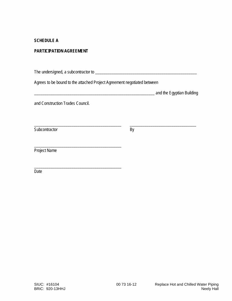
SIUC: #16104 00 73 16-12 Replace Hot and Chilled Water Piping BRiC: 920-13HHJ Neely Hall
SCHEDULE A PARTICIPATION AGREEMENT The undersigned, a subcontractor to _________________________________________________ Agrees to be bound to the attached Project Agreement negotiated between __________________________________________________________ and the Egyptian Building and Construction Trades Council. __________________________________________ ________________________________ Subcontractor By __________________________________________ Project Name __________________________________________ Date
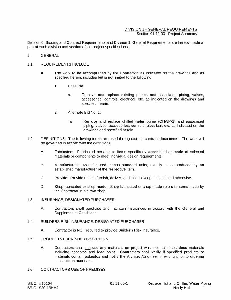
SIUC: #16104 01 11 00-1 Replace Hot and Chilled Water Piping BRiC: 920-13HHJ Neely Hall
DIVISION 1 - GENERAL REQUIREMENTS Section 01 11 00 - Project Summary Division 0, Bidding and Contract Requirements and Division 1, General Requirements are hereby made a part of each division and section of the project specifications. 1. GENERAL 1.1 REQUIREMENTS INCLUDE
A. The work to be accomplished by the Contractor, as indicated on the drawings and as specified herein, includes but is not limited to the following:
1. Base Bid:
a. Remove and replace existing pumps and associated piping, valves, accessories, controls, electrical, etc. as indicated on the drawings and specified herein.
2. Alternate Bid No. 1:
a. Remove and replace chilled water pump (CHWP-1) and associated piping, valves, accessories, controls, electrical, etc. as indicated on the drawings and specified herein.
1.2 DEFINITIONS. The following terms are used throughout the contract documents. The work will
be governed in accord with the definitions. A. Fabricated: Fabricated pertains to items specifically assembled or made of selected
materials or components to meet individual design requirements. B. Manufactured: Manufactured means standard units, usually mass produced by an
established manufacturer of the respective item. C. Provide: Provide means furnish, deliver, and install except as indicated otherwise. D. Shop fabricated or shop made: Shop fabricated or shop made refers to items made by
the Contractor in his own shop. 1.3 INSURANCE, DESIGNATED PURCHASER.
A. Contractors shall purchase and maintain insurances in accord with the General and Supplemental Conditions.
1.4 BUILDERS RISK INSURANCE, DESIGNATED PURCHASER.
A. Contractor is NOT required to provide Builder’s Risk Insurance. 1.5 PRODUCTS FURNISHED BY OTHERS A. Contractors shall not use any materials on project which contain hazardous materials
including asbestos and lead paint. Contractors shall verify if specified products or materials contain asbestos and notify the Architect/Engineer in writing prior to ordering construction materials.
1.6 CONTRACTORS USE OF PREMISES
SIUC: #16104 01 11 00-2 Replace Hot and Chilled Water Piping BRiC: 920-13HHJ Neely Hall
A. Confine operations at site to areas permitted by: 1. Law. 2. Permits. 3. Contract. 4. Owner's representative. a. Confer with Owner's field representative and obtain full knowledge of all
site rules and regulations affecting work. b. Conform to site rules and regulations while engaged in project
construction. c. Site rules and regulations take precedence over others that may exist
outside such jurisdiction. d. Vehicle use: Rigidly enforce the following: 1. Keep all vehicles, mechanized or motorized equipment locked at
all times when parked and unattended on Owner's premises. 2. Do not, under any circumstances, leave any vehicle unattended
with motor or engine running, or with ignition key in place. 3. Parking: As directed by Owner’s field representative. 4. All traffic control subject to Owner's field representative's
approval. B. Do not unreasonably encumber site with materials or equipment. C. Do not load structure with weight that will endanger structure. D. Assume full responsibility for protection and safekeeping of products stored on premises. E. Move all stored products or equipment which interferes with Owner or other Contractors. F. Obtain and pay for use of additional storage or work area needed for operations. G. Limit use of site for work and storage: 1. Coordinate with Owner restrictions including access, parking as required. 2. All Contractors' equipment shall be secured at the end of each working day. 3. The Contractors will be required to provide toilet facilities as required by the
General and Supplemental Conditions. 4. The Contractors will be allowed to use the Owner's water and electrical on a
limited basis. 5. The Contractors' trash and debris shall be removed from the project site at the
end of each working day as indicted by the General and Supplemental Conditions.
H. The Contractors shall be solely responsible for all and any damage to the Owner’s
property as a result of their operations including (building, sidewalks, roads, lawn, etc.) and shall provide complete and immediate repair/replacement as required by the Owner at the Contractors’ sole expense.
1.7 SUPERVISON OF THE WORK
A. The Contractors shall be solely responsible for supervising the work including site safety and all construction means, methods, techniques, sequences and procedures, and coordinating all portions of the work under this contract.
SIUC: #16104 01 11 00-3 Replace Hot and Chilled Water Piping BRiC: 920-13HHJ Neely Hall
B. The Contractors shall be solely responsible for properly and accurately laying out all work
and for all lines, levels, elevations, and measurements for all work under this contract.
C. The Contractors shall provide competent and adequate staff as necessary for the proper administration, coordination, and supervision of the work; organize the procurement of all materials and equipment so that they will be available at all times as needed for the timely completion of the work; and maintain an adequate work force of skilled workers on the job to properly complete the work in a timely manner in compliance with the required completion dates.
D. Each Contractor shall provide a competent superintendent satisfactory to SIUC and
Architect/Engineer, who shall be in attendance at the site throughout the active performance of the work, and at such other times as may be necessary, and who shall be authorized to commit the Contractor with regard to manpower, schedule, coordination and cooperation.
1.8 EXISTING ASBESTOS CONTAINING MATERIALS (ACM’s)
A. Contractor is advised that there are existing ACM’s that will remain as is. Contractor shall exercise extreme caution when working around the ACM ceilings and all asbestos containing materials. Contractor shall contact A/E immediately if their work will disturb any ACM’s.
1.9 CONTRACT PERIOD
A. Contractor shall have access to the project site to begin work on May 15, 2017, and be substantially complete by July 31, 2017
END OF SECTION

SIUC: #16104 01 11 00-1 Replace Hot and Chilled Water Piping BRiC: 920-13HHJ Neely Hall
DIVISION 1 - GENERAL REQUIREMENTS 01 23 00 - Alternate Bids
1. GENERAL 1.1 REQUIREMENTS INCLUDE:
A. Designated Contractors: Provide Alternate Bid prices in Bid Form for specified alternate work.
B. Each Contractor coordinate all related and required work necessary to perform work specified in alternate bids, when accepted and awarded.
2. DESCRIPTION OF ALTERNATE BIDS 2.1 Heating Contract:
A. Alternate Bid No. 1: Remove and replace chilled water pump (CHWP-1) and associated piping, valves, accessories, controls, electrical, etc. as indicated on the drawings and specified herein.
1. Pertinent work specified elsewhere
a. Section 23 05 14 – Variable Frequency Drives. b. Section 23 05 19 – Gages and Meters for HVAC Piping. c. Section 23 05 23 – General Duty Valves for HVAC Piping. d. Section 23 05 29 – Hangers and Supports for HVAC Piping and Equipment. e. Section 23 05 48 - Seismic Controls for HVAC Piping and Equipment. f. Section 23 05 53 – Identification for HVAC Piping and Equipment. g. Section 23 05 93 – Testing, Adjusting and Balancing for HVAC. h. Section 23 07 00 – HVAC Insulation. i. Section 23 09 00 – HVAC Instrumentation and Controls. j. Section 23 09 00A – HVAC Instrumentation and Controls (Appendix A). k. Section 23 21 13 – Hydronic Piping. l. Section 23 21 23 – Hydronic Pumps. m. Section 26 05 19 – Building Wire & Cable. n. Section 26 05 26 - Grounding & Bonding for Electrical Systems. o. Section 26 05 29 – Supporting Devices. p. Section 26 05 33 – Conduit. q. Section 26 05 35 – Boxes. r. Section 26 05 53 - Identification for Electrical Systems. s. Section 26 24 16 – Panelboards. t. Section 26 28 16 – Enclosed Switches
END OF SECTION
SIUC: #16104 01 29 73-1 Replace Hot and Chilled Water Piping BRiC: 920-13HHJ Neely Hall
DIVISION 1 - GENERAL REQUIREMENTS Section 01 29 73 - Schedule of Values 1. GENERAL 1.1 REQUIREMENTS INCLUDE A. Each Contractor:
1. Submit a detailed Schedule of Values to Architect/Engineer at least 15 business days prior to submitting first application for payment.
2. Support values given with data to substantiate their correctness. 3. Submit detailed quantities of designated materials. 4. Use Schedule of Values as only basis for application for payment.
B. Payment for materials stored on or off site will be limited to those materials listed in Schedule of Values.
1.2 FORM OF SUBMITTAL A. Use Project Manual Table of Contents as basis of format for listing detailed costs of all
work. B. Identify each line item with number and title listed in Project Manual Table of Contents.
1.3 PREPARATION A. Itemize separate line item cost for each of following cost items: 1. Overhead and profit. 2. Bonds. 3. Insurance. 4. General requirements. a. Break down general requirements to temporary facilities. Show initial
installation and maintenance and fuel consumption.
B. Itemize separate line item cost for work specified in each section of the specifications. Identify work of:
1. Contractors' own labor forces.
2. All subcontractors. 3. All major suppliers of products or equipment. C. Break down installed costs into: 1. Delivered cost of product. 2. Labor cost, excluding overhead and profit.
D. For each line item break down costs to list major products or operations under each item. 1. Contractor's, subcontractor, or supplier. 2. Specification section number. 3. Description of work or material. 4. Quantity.

SIUC: #16104 01 29 73-2 Replace Hot and Chilled Water Piping BRiC: 920-13HHJ Neely Hall
5. Scheduled value. 6. % of Contract. E. Round off figures to nearest dollar. F. Make sum of total costs of all items listed in schedule equal to total contract sum. G. Schedule of values shall break down costs in detail for review, written approval by the
Architect/Engineer, including sequencing of the work. H. Schedule of Values shall be adequately broken down and detailed as required by
Architect/Engineer. 1.4 REVIEW AND RESUBMITTAL
A. After review by Architect/Engineer, revise and resubmit Schedule of Values as directed. Follow original submittal procedure.
1.5 UPDATE A. Update Schedule of Values when: 1. Directed by Architect/Engineer. 2. Change of subcontractor or supplier occurs. 3. Change of product or equipment occurs.
B. Provide a final updated schedule of values at the project closeout for the
Architect/Engineer review and approval. 1.6 SAMPLE A. Electronic .pdf copy for Contractor’s use may be found at the following website address:
http://www.pso.siu.edu/construction/forms/csv.pdf B. Sample Contractor's Schedule of Values (CSV) Form:
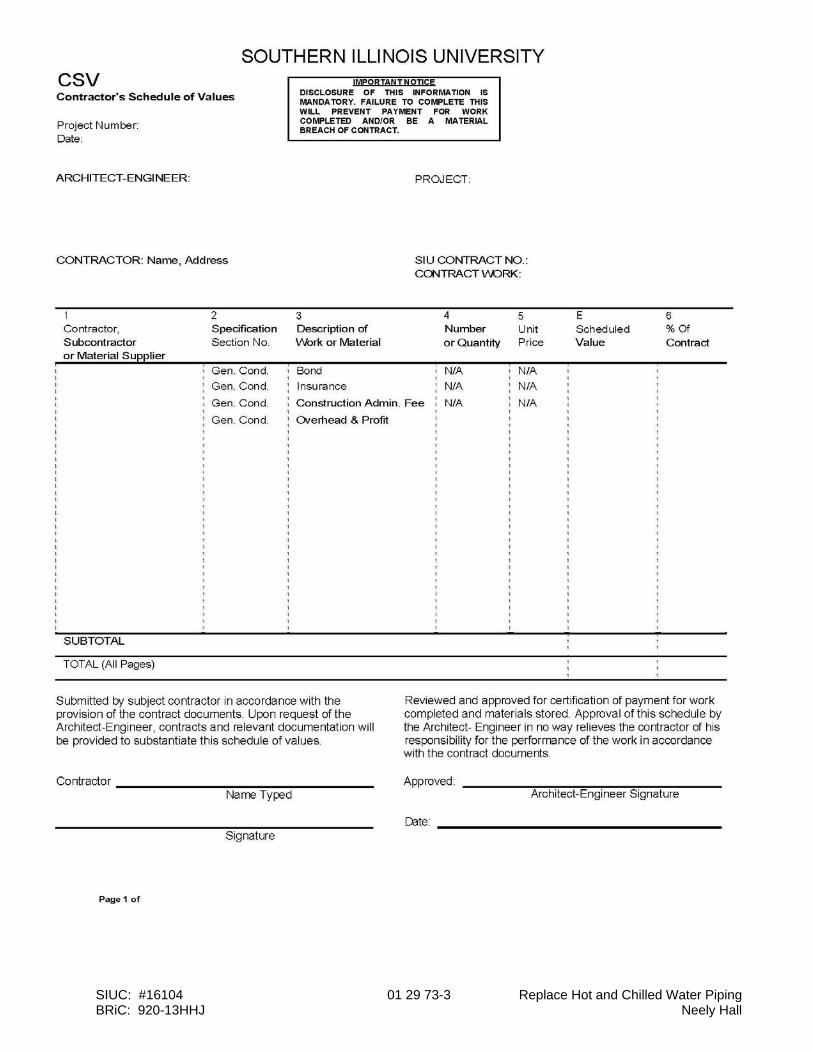
SIUC: #16104 01 29 73-3 Replace Hot and Chilled Water Piping BRiC: 920-13HHJ Neely Hall
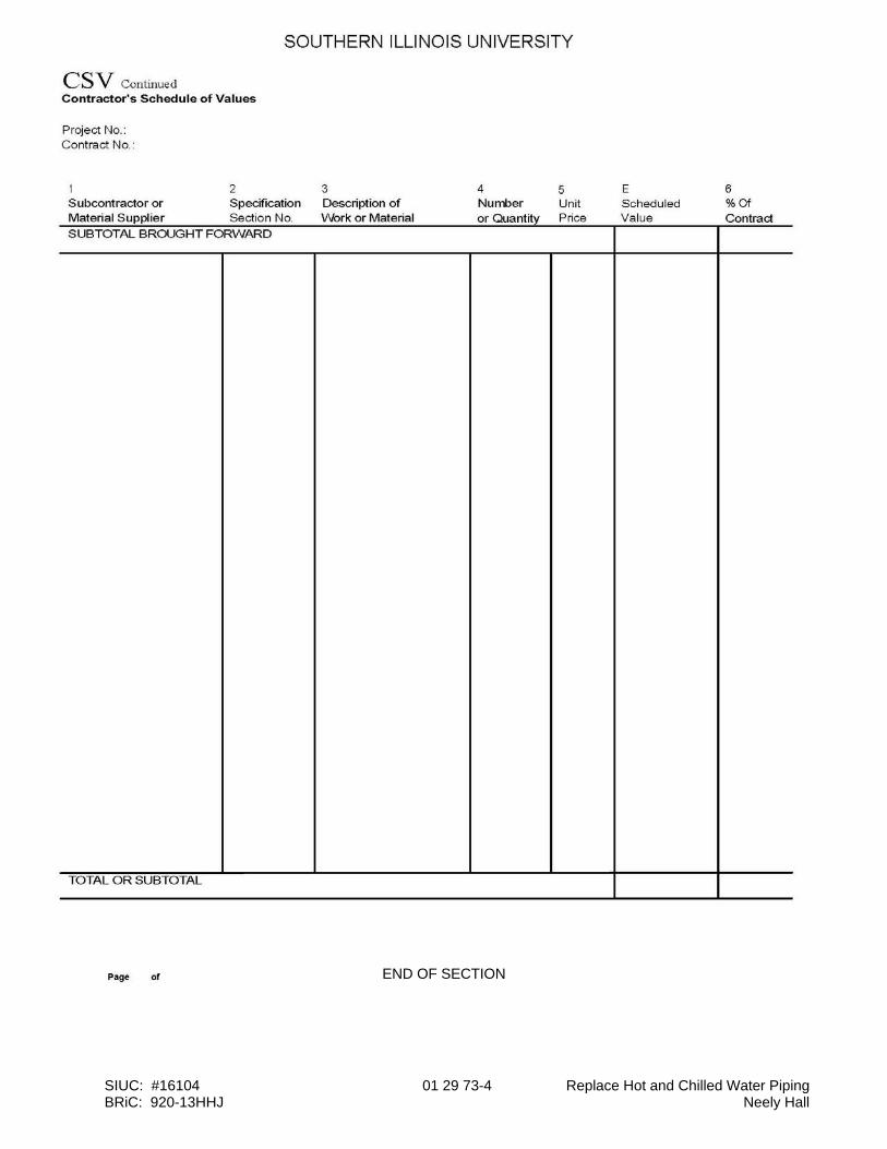
SIUC: #16104 01 29 73-4 Replace Hot and Chilled Water Piping BRiC: 920-13HHJ Neely Hall
END OF SECTION
SIUC: #16104 01 31 19-1 Replace Hot and Chilled Water Piping BRiC: 920-13HHJ Neely Hall
DIVISION 1 - GENERAL REQUIREMENTS Section 01 31 19 - Project Meetings 1. GENERAL 1.1 REQUIREMENTS INCLUDE A. Each Contractor: 1. Each Contractor and key Sub-Contractors shall attend monthly pay meetings.
a. Verify and coordinate project meeting requirements with General and Supplemental Conditions prior to bid as required
1.2 RELATED REQUIREMENTS A. Specified elsewhere: 1. Division 0 - Bidding and Contract Requirements. 2. 01 11 00 - Project Summary. 3. 01 29 73 - Schedule of Values. 4. 01 77 00 - Contract Closeout. 5. 01 78 30 - Warranties and Bonds. 1.3 PRECONSTRUCTION MEETING A. Architect will schedule within ten business days after Notice of Award. B. Attendance: 1. Owner's Representative. 2. Architect/Engineer 3. Each Contractor. C. Minimum Agenda: 1. Distribute and discuss: a. List of major subcontractors. b. Construction schedule. 2. Critical work sequencing. 3. Designation of responsible personnel. 4. Establish chain of authority. 5. Processing of field decisions and change orders. 6. Adequacy of distribution of contract documents. 7. Submittal: a. Schedules. b. Manufacturer's certification of products. c. Schedule of values. d. Manpower reports. 8. Major equipment deliveries and priorities.
SIUC: #16104 01 31 19-2 Replace Hot and Chilled Water Piping BRiC: 920-13HHJ Neely Hall
9. Procedures for maintaining record documents. 10. Use of premises: a. Office and storage areas. b. Access. c. Owner's requirements. 11. Safety and first aid procedures. 12. Security procedures. 13. Housekeeping procedures. 14. Construction trailer. 15. Pay meetings including dates, time, and location. 16. Architect/Engineer observation. 17. Barriers. 18. Construction 19. Access roads. 20. Temporary utilities. 1.4 PAYMENT MEETING A. Architect will schedule and administer payment/progress meetings. 1. Prepare agenda. 2. Distribute written notice and agenda of regular and called meetings 10 business
days in advance of meeting date. 3. Record minutes; include significant proceedings and decisions.
4. Distribute copies of minutes to participants within five business days after meetings.
B. Attendance: 1. Owner’s Representative. 2. Architect/Engineer 3. Each Contractor.
4. All key sub-contractors.
END OF SECTION
SIUC: #16104 01 33 23-1 Replace Hot and Chilled Water Piping BRiC: 920-13HHJ Neely Hall
DIVISION 1 - GENERAL REQUIREMENTS Section 01 33 23 - Shop Drawings, Product Data & Samples 1. GENERAL 1.1 REQUIREMENTS INCLUDE A. Each Contractor shall make submittals to the Engineer. 1.2 RELATED REQUIREMENTS A. Specified elsewhere: 1. Division 0 – General Conditions. 1.3 DEFINITIONS
A. Shop drawings: Shop drawings are original drawings prepared by Contractor, subcontractor, sub-subcontractor, supplier or distributor, which illustrate some portion of the work, showing fabrication, lay-out, setting, or erection details as they relate to specific job conditions.
1. Prepared by qualified detailer. 2. Identify details by reference to sheet and detail numbers shown on contract
drawings. 3. Submit 3 copies (min.). B. Product Data: 1. Manufacturer's standard schematic drawings; edited to fit this project. a. Modify to delete information which is not applicable to project. b. Supplement standard information to provide additional information
applicable to project. 2. Manufacturer's catalog sheets, brochures, diagrams, schedules, performance
charts, illustrations, and other standard descriptive data: a. Clearly mark each copy to identify pertinent materials, products, or
models. b. Show dimensions and clearances. 1.4 CONTRACTOR RESPONSIBILITIES A. Review shop drawings, product data, and samples prior to submission to the next level of
authority. Affix stamp, date, and initials or signature certifying to review of submittal, and with instructions for Contractor response.
B. Verify:
SIUC: #16104 01 33 23-2 Replace Hot and Chilled Water Piping BRiC: 920-13HHJ Neely Hall
1. Field dimensions and elevations. 2. Field construction criteria. 3. Catalog numbers and similar data. C. Coordinate each submittal with requirements of: 1. The Work. 2. The Contract Documents. D. Contractor's responsibility for errors, omissions, or deviation from contract documents in
submittals is not relieved by Owner's review of submittals.
E. Prior to submission, notify Architect/Engineer in writing of all proposed deviations in submittals from contract requirements. Substitution of materials or equipment may only be approved by change order.
F. Contractor's responsibility for deviations in submittals from contract document
requirements is not relieved by Architect/Engineer’s review of submittals.
G. Contractor's responsibility for project coordination, verification of existing conditions, determining accuracy and completeness of other details, such as dimensions and quantities, and for installation and performance of equipment or systems as an overall assembly is not relieved by Architect/Engineer’s review of submittals.
H. Do not begin any work which requires submittals without having Architect/Engineer’s
initials or signature indicating approval. I. After Architect/Engineer’s review, make response required by Architect/Engineer and
distribute copies. Indicate by transmittal that copy of approved data has been delivered to installer.
1.5 A/E'S DUTIES A. Review submittals within 7 business days. B. Review for: 1. Design concept of project. 2. Compliance with contract documents. C. Review all requests for proposed deviations. Obtain Architect/Engineer’s concurrence
and respond to Contractor's request. D. Review of separate item does not constitute review of an assembly in which item
functions. E. Affix stamp, date, and initials or signature certifying to review of submittal, and with
instructions for Contractor response. F. Return submittals to sender for response or distribution.

SIUC: #16104 01 33 23-3 Replace Hot and Chilled Water Piping BRiC: 920-13HHJ Neely Hall
1.6 SPECIFIED SUBMITTALS. Owner may require additional submittals at any time.
END OF SECTION
SIUC: #16104 01 77 00-1 Replace Hot and Chilled Water Piping BRiC: 920-13HHJ Neely Hall
DIVISION 1 - GENERAL REQUIREMENTS Section 01 77 00 - Contract Closeout 1. GENERAL 1.1. REQUIREMENTS INCLUDE A. Each Contractor provide: 1. Substantial completion. 2. Final completion. 3. Closeout submittals. 4. Application for final payment. 5. Spare parts. 6. Maintenance materials. 7. Warranties. 1.2. RELATED REQUIREMENTS A. Specified elsewhere: 1. 01 11 00 - Project Summary. 2. 01 74 00 - Construction Cleaning. 3. 01 73 23 - Operating & Maintenance Data. 4. 01 78 30 - Warranties & Bonds. 1.3. SUBSTANTIAL COMPLETION A. When Contractor considers work is substantially complete, submit written declaration to
Owner and Architect/Engineer that work or designated portion thereof, is substantially complete. Include list of items to be completed or corrected.
B. Prior to preliminary substantial completion and inspection: 1. Submit: a. Guarantees, warranties and bonds. C. Each Contractor:
1. Complete all work listed for completion or correction within designated time. 2. Perform final cleaning. 1.4. FINAL COMPLETION A. Each Contractor provide: 1. Submit written declaration to the Owner and Architect/Engineer that:
a. Work complies with all aspects of contract documents. b. All items on substantial completion punch list have been completed or
corrected. c. All tools, construction equipment and surplus materials have been
SIUC: #16104 01 77 00-2 Replace Hot and Chilled Water Piping BRiC: 920-13HHJ Neely Hall
removed from site. 1.5. CLOSEOUT SUBMITTALS
A. Provide submittals to the Owner and Architect/Engineer that are required by governing or other authorities.
1.6. APPLICATION FOR FINAL PAYMENT A. Each Contractor submit duly executed to the Owner and Architect/Engineer: 1. Final Application and Certificate of Payment. 2. Contractor's Final Declaration (CFD). 3. Separate releases of waivers of liens for all subcontractors, suppliers and others
with lien rights against property of Owner, together with complete list of those parties.
4. Final accounting statement, reflecting all adjustments to contract sum: a. Original contract sum. b. Additions and deductions resulting from: 1. All change orders. 2. Deductions for uncorrected work. 3. Total contract sum, adjusted. 4. Previous payments. 5. Sum remaining due. 1.7. SPARE PARTS AND MAINTENANCE MATERIALS
A. Provide products, spare parts, maintenance and extra materials in quantities specified in
individual specification sections.
B. Deliver to location as directed by Owner. Obtain receipt prior to final payment.
END OF SECTION
SIUC: #16104 01 78 23-1 Replace Hot and Chilled Water Piping BRiC: 920-13HHJ Neely Hall
DIVISION 1 - GENERAL REQUIREMENTS Section 01 78 23 - Operating & Maintenance Data 1. GENERAL 1.1. REQUIREMENTS INCLUDE A. Each Contractor provide: 1. Compile product data and related information appropriate for Owner's
maintenance of products. 2. Instruct Owner's personnel in maintenance of products. 3. Provide O&M Manuals in electronic format.
1.2. RELATED REQUIREMENTS A. Specified elsewhere: 1. 01 33 23 - Shop Drawings, Product Data & Samples. 2. 01 77 00 - Contract Closeout. 3. 01 74 30 - Warranties & Bonds. 1.3. SUBMITTALS A. Form: Manufacturer's standard product or equipment data of same type and form
furnished to manufacturer's maintenance personnel. 1.4. MANUAL CONTENT A. Neatly typewritten table of contents for each volume, arranged in systematic order.
Follow Project Manual format.
1. Contractor name, name of responsible principal, address and telephone number. 2. List of each product specified to be included, indexed to volume content.
3. List with each product, the name, address and telephone number of: a. Subcontractor. b. Maintenance contractor, as appropriate. c. Identify area of responsibility of each. d. Local supply source for parts and replacement. B. Product Data: 1. Include only sheets pertinent to specific product. 2. Annotate each sheet to: a. Clearly identify specific product or part installed. b. Clearly identify data applicable to installation. c. Delete references to inapplicable installation. C. Drawings:

SIUC: #16104 01 78 23-2 Replace Hot and Chilled Water Piping BRiC: 920-13HHJ Neely Hall
1. Supplement product data with drawings to clearly illustrate: a. Relationship of component parts of product. D. Written text to supplement product data for particular installation:
1. Organize in consistent format under separate headings for different procedures. 2. Provide logical sequence of instructions for each procedure. E. Copy of each warranty, bond and service contract issued. 1. Provide information sheet for Owner's personnel. Give: a. Proper procedures in event of failure. b. Instances which might affect validity of warranties or bonds. 1.5. MANUAL FOR MATERIALS AND FINISHES A. Submit complete manual in final form to the Architect/Engineer. B. Content for products, applied materials and finishes: 1. Manufacturer's data, giving full information on products. a. Catalog number, size, composition. b. Color and texture designations. c. Information for re-ordering special-manufactured products. 2. Instructions for care and maintenance. a. Recommend maintenance schedule. C. Content, for moisture-protection and weather-exposed products. 1. Manufacturer's data, giving full product information. a. Applicable standards. b. Chemical composition. c. Installation details. 2. Instructions for inspection, maintenance and repair. D. Additional maintenance data requirements: Respective specification sections. E. Provide complete information for products specified: Respective specification sections. 1.6. INSTRUCTION OF OWNER'S PERSONNEL A. Prior to final inspection or acceptance, fully instruct Owner's designated maintenance
personnel in the maintenance of all products. B. Maintenance manual shall constitute the basis of instruction.
SIUC: #16104 01 78 23-3 Replace Hot and Chilled Water Piping BRiC: 920-13HHJ Neely Hall
1. Review contents of manual with personnel in full detail to explain all aspects of maintenance.
END OF SECTION
SIUC: #16104 01 78 30-1 Replace Hot and Chilled Water Piping BRiC: 920-13HHJ Neely Hall
DIVISION 1 - GENERAL REQUIREMENTS Section 01 78 30 - Warranties & Bonds (Beyond One Year) 1. GENERAL 1.1. REQUIREMENTS INCLUDE A. Each Contractor provide: 1. Compile specified warranties and bonds. 2. Co-execute specified submittals. 3. Review submittals. Verify compliance with contract documents.
4. Submit in Electronic Form. 1.2. RELATED REQUIREMENTS A. Specified elsewhere: 1. 01 77 00 - Contract Closeout. 2. General Conditions and Supplemental 1.3. SUBMITTAL REQUIREMENTS A. Assemble warranties and bonds, properly executed by each of the respective
manufacturers, subcontractors and suppliers. B. Submit one original signed copy of each item. C. Table of Contents: Neatly typed in orderly sequence; follow 1.6. 1. Product or work item. 2. Firm, with principal's name, address and telephone number. 3. Scope. 4. Date of beginning of warranty or bond (in accord with Supplementary Conditions). 5. Duration of warranty bond. 6. Provide information for Owner's personnel: Proper procedure in case of product
or equipment failure. 7. Contractor; responsible principal's name, address and telephone number. 1.4. FORM OF SUBMITTALS A. Prepare a single packet. B. Format 8-1/2 inches x 11 inches. Fold larger sheets to fit.
C. Cover: Identify each packet with typed title "WARRANTIES & BONDS." List: 1. Project number and title. 2. Contractor's name. 3. Contract. 1.5. TIME OF SUBMITTALS. Coordinate with 01 33 23. 1.6. SUBMITTALS REQUIRED
SIUC: #16104 01 78 30-2 Replace Hot and Chilled Water Piping BRiC: 920-13HHJ Neely Hall
A. Submit warranties and bonds required in respective specification sections.
END OF SECTION
SIUC: #16104 23 05 14-1 Replace Hot and Chilled Water Piping BRiC: 920-13HHJ Neely Hall
DIVISION 23 - HEATING VENTILATING AND AIR CONDITIONING Section 23 05 14 - Variable Frequency Drives
1. GENERAL 1.1 WORK INCLUDES
A. Base Bid:
1. Heating Contractor Shall Provide:
a. Variable frequency drive (VFD) packages for specified equipment. VFD’s shall be provided with the Building Automation System. Refer to Section 230900 – HVAC Instrumentation and Controls.
b. Power wiring/conduit to VFD, motor wiring/conduit from VFD to motor and final connections.
B. Alternate Bid No. 1:
1. Heating Contractor Shall Provide Variable Frequency Drive for CHWP-1:
a. Variable frequency drive (VFD) packages for specified equipment. VFD’s shall be provided with the Building Automation System. Refer to Section 230900 – HVAC Instrumentation and Controls.
b. Power wiring/conduit to VFD, motor wiring/conduit from VFD to motor and final connections.
1.2 REFERENCES
A. NFPA 70 - National Electrical Code.
B. NEMA ICS 3.1 - Safety Standards for Construction and Guide for Selection, Installation and Operation of Adjustable Speed Drive Systems.
C. NEMA 250 - Enclosures for Electrical Equipment (1000 Volts Maximum).
1.3 QUALITY ASSURANCE
A. Manufacturer Qualifications: Company specializing in manufacturing the Products specified in this section with minimum three years experience.
B. The complete VFD, including all optional features, shall be factory tested. The VFD shall
operate a dynamometer at full load and the load and speed shall be cycled during the test. 1.4 REGULATORY REQUIREMENTS
A. Conform to requirements of NFPA 70.
B. Furnish products listed and classified by Underwriters Laboratories, Inc. as suitable for purpose specified and indicated.
1.5 DELIVERY, STORAGE, AND HANDLING
A. Accept controllers on site in original packing. Inspect for damage.
B. Store in a clean, dry space. Maintain factory wrapping or provide an additional heavy canvas or heavy plastic cover to protect units from dirt, water, construction debris, and traffic.
SIUC: #16104 23 05 14-2 Replace Hot and Chilled Water Piping BRiC: 920-13HHJ Neely Hall
C. Handle in accordance with manufacturer's written instructions. Lift only with lugs provided for
the purpose. Handle carefully to avoid damage to components, enclosure, and finish. 1.6 FIELD MEASUREMENTS
A. Verify that field measurements are as indicated on shop drawings.
1.7 SUBMITTALS
A. Product Data: For each type of product indicated.
B. Wiring Diagrams: For power, signal, and control wiring.
C. Operation and Maintenance Data: For meters and gages to include in operation and maintenance manuals.
2. PRODUCTS 2.1 VARIABLE FREQUENCY DRIVES
A. Manufacturers:
1. Square D. 2. Yaskawa. 3. ABB.
B. Equipment requiring VFD:
1. Hot/Chilled Water Pumps (HCWP’s):
a. HCWP-1: 3 hp. b. HCWP-2: 5 hp. c. HCWP-3: 5 hp. d. HCWP-4: 7-1/2 hp.
2. Hot water pump (HWP -1): 7-1/2 hp. 3. Chilled water pump (CHWP -1): 7-1/2 hp.
C. General:
1. The control system shall include as a minimum adjustable frequency drive(s) and
remote sensor/transmitters as indicated on the plans. Provide additional items as specified or as required to properly execute the sequence of operation.
2. Provide complete variable frequency drives as specified herein for pumps as indicated on the schedules. All standard and optional features shall be included within the VFD enclosure, unless otherwise specified. VFD shall be housed in a metal NEMA 1 enclosure. VFD associated with EF-1 shall be enclosed in a NEMA 3R enclosure.
3. The VFD shall convert incoming fixed frequency three-phase AC power into a variable frequency and voltage for controlling the speed of three phase AC motors. The motor current shall closely approximate a sine wave. Motor voltage shall be varied with frequency to maintain desired motor magnetization current suitable for centrifugal pump and fan control.
4. An advanced sine wave approximation and voltage vector control shall be used to allow operation at rated motor shaft output at nominal speed with no derating. This voltage vector control shall minimize harmonics to the motor to increase motor efficiency and life.
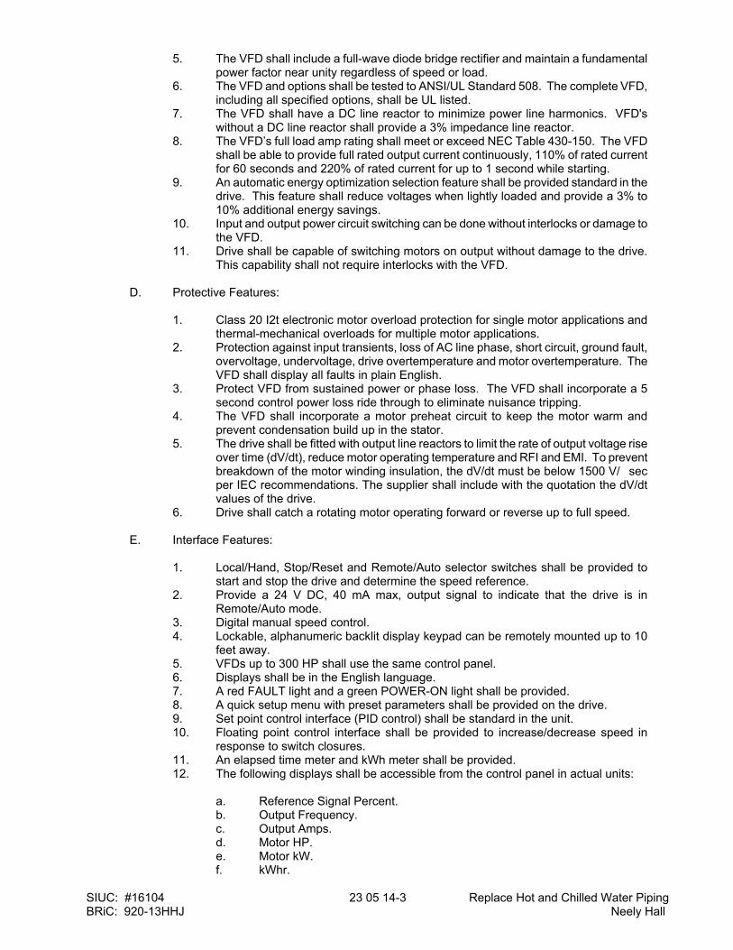
SIUC: #16104 23 05 14-3 Replace Hot and Chilled Water Piping BRiC: 920-13HHJ Neely Hall
5. The VFD shall include a full-wave diode bridge rectifier and maintain a fundamental power factor near unity regardless of speed or load.
6. The VFD and options shall be tested to ANSI/UL Standard 508. The complete VFD, including all specified options, shall be UL listed.
7. The VFD shall have a DC line reactor to minimize power line harmonics. VFD's without a DC line reactor shall provide a 3% impedance line reactor.
8. The VFD’s full load amp rating shall meet or exceed NEC Table 430-150. The VFD shall be able to provide full rated output current continuously, 110% of rated current for 60 seconds and 220% of rated current for up to 1 second while starting.
9. An automatic energy optimization selection feature shall be provided standard in the drive. This feature shall reduce voltages when lightly loaded and provide a 3% to 10% additional energy savings.
10. Input and output power circuit switching can be done without interlocks or damage to the VFD.
11. Drive shall be capable of switching motors on output without damage to the drive. This capability shall not require interlocks with the VFD.
D. Protective Features:
1. Class 20 I2t electronic motor overload protection for single motor applications and
thermal-mechanical overloads for multiple motor applications. 2. Protection against input transients, loss of AC line phase, short circuit, ground fault,
overvoltage, undervoltage, drive overtemperature and motor overtemperature. The VFD shall display all faults in plain English.
3. Protect VFD from sustained power or phase loss. The VFD shall incorporate a 5 second control power loss ride through to eliminate nuisance tripping.
4. The VFD shall incorporate a motor preheat circuit to keep the motor warm and prevent condensation build up in the stator.
5. The drive shall be fitted with output line reactors to limit the rate of output voltage rise over time (dV/dt), reduce motor operating temperature and RFI and EMI. To prevent breakdown of the motor winding insulation, the dV/dt must be below 1500 V/�sec per IEC recommendations. The supplier shall include with the quotation the dV/dt values of the drive.
6. Drive shall catch a rotating motor operating forward or reverse up to full speed.
E. Interface Features:
1. Local/Hand, Stop/Reset and Remote/Auto selector switches shall be provided to start and stop the drive and determine the speed reference.
2. Provide a 24 V DC, 40 mA max, output signal to indicate that the drive is in Remote/Auto mode.
3. Digital manual speed control. 4. Lockable, alphanumeric backlit display keypad can be remotely mounted up to 10
feet away. 5. VFDs up to 300 HP shall use the same control panel. 6. Displays shall be in the English language. 7. A red FAULT light and a green POWER-ON light shall be provided. 8. A quick setup menu with preset parameters shall be provided on the drive. 9. Set point control interface (PID control) shall be standard in the unit. 10. Floating point control interface shall be provided to increase/decrease speed in
response to switch closures. 11. An elapsed time meter and kWh meter shall be provided. 12. The following displays shall be accessible from the control panel in actual units:
a. Reference Signal Percent. b. Output Frequency. c. Output Amps. d. Motor HP. e. Motor kW. f. kWhr.
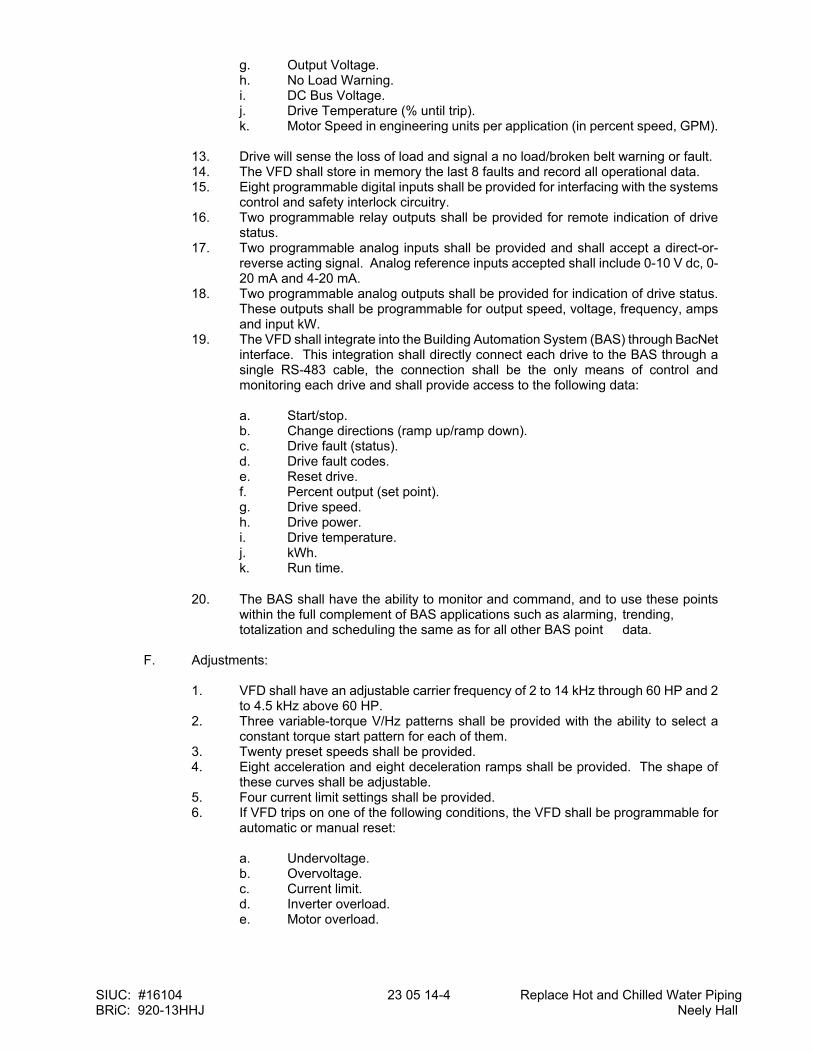
SIUC: #16104 23 05 14-4 Replace Hot and Chilled Water Piping BRiC: 920-13HHJ Neely Hall
g. Output Voltage. h. No Load Warning. i. DC Bus Voltage. j. Drive Temperature (% until trip). k. Motor Speed in engineering units per application (in percent speed, GPM).
13. Drive will sense the loss of load and signal a no load/broken belt warning or fault. 14. The VFD shall store in memory the last 8 faults and record all operational data. 15. Eight programmable digital inputs shall be provided for interfacing with the systems
control and safety interlock circuitry. 16. Two programmable relay outputs shall be provided for remote indication of drive
status. 17. Two programmable analog inputs shall be provided and shall accept a direct-or-
reverse acting signal. Analog reference inputs accepted shall include 0-10 V dc, 0-20 mA and 4-20 mA.
18. Two programmable analog outputs shall be provided for indication of drive status. These outputs shall be programmable for output speed, voltage, frequency, amps and input kW.
19. The VFD shall integrate into the Building Automation System (BAS) through BacNet interface. This integration shall directly connect each drive to the BAS through a single RS-483 cable, the connection shall be the only means of control and monitoring each drive and shall provide access to the following data:
a. Start/stop. b. Change directions (ramp up/ramp down). c. Drive fault (status). d. Drive fault codes. e. Reset drive. f. Percent output (set point). g. Drive speed. h. Drive power. i. Drive temperature. j. kWh. k. Run time.
20. The BAS shall have the ability to monitor and command, and to use these points within the full complement of BAS applications such as alarming, trending, totalization and scheduling the same as for all other BAS point data.
F. Adjustments:
1. VFD shall have an adjustable carrier frequency of 2 to 14 kHz through 60 HP and 2
to 4.5 kHz above 60 HP. 2. Three variable-torque V/Hz patterns shall be provided with the ability to select a
constant torque start pattern for each of them. 3. Twenty preset speeds shall be provided. 4. Eight acceleration and eight deceleration ramps shall be provided. The shape of
these curves shall be adjustable. 5. Four current limit settings shall be provided. 6. If VFD trips on one of the following conditions, the VFD shall be programmable for
automatic or manual reset:
a. Undervoltage. b. Overvoltage. c. Current limit. d. Inverter overload. e. Motor overload.

SIUC: #16104 23 05 14-5 Replace Hot and Chilled Water Piping BRiC: 920-13HHJ Neely Hall
7. The number of restart attempts shall be selectable from 0 through 10 and the time between attempts shall be adjustable from 0 through 10 seconds.
G. Service Conditions:
1. Ambient temperature, -10 to 40�C (14 to 104�F). 2. 0 to 95% relative humidity, non-condensing. 3. Elevation to 3,300 feet without derating. 4. AC line voltage variation, -10 to +10% of nominal with full output. 5. No side clearance shall be required for cooling of wall mount units and all power and
control wiring shall be done from the bottom. 6. Drive shall be capable of operating a motor up to 1,000 feet away without derating or
field modification.
H. Accessories:
1. Circuit breaker to serve as means of disconnect. 2. Provide the necessary line reactors to limit harmonic distortion to 3% THD (voltage)
and 8% THD (current) and commutation notch area to 16,400 volt-microsecond with source impedance no more than 0.1 PU of drive size.
3. Bypass: Provide a manual bypass consisting of a door interlocked main fused disconnect pad-lockable in the off position, separate drive disconnect, a built-in motor starter and a four position DRIVE/OFF/LINE/TEST switch controlling three contactors. In the DRIVE position, the motor is operated at an adjustable speed from the drive. In the OFF position, the motor and drive are disconnected. In the LINE position, the motor is operated at full speed from the AC power line and power is disconnected from the drive, so that service can be performed. In the TEST position, the motor is operated at full speed from the AC line power. This allows the drive to be given an operational test while continuing to run the motor at full speed in bypass. Customer supplied normally closed dry contact shall be interlocked with the drives safety trip circuitry to stop the motor whether in DRIVE or BYPASS mode in case of an external safety fault.
I. Warranty: The VFD shall be warranted by the manufacturer for a period of 36 months. The
warranty shall include parts, labor, travel costs and living expenses incurred by the manufacturer to provide factory authorized on-site service.
3. EXECUTION 3.1 EXAMINATION
A. Verify that surface is suitable for controller installation.
B. Do not install controller until building environment can be maintained within the service conditions required by the manufacturer.
3.2 INSTALLATION
A. Install controller where indicated, in accordance with manufacturer's written instructions and NEMA ICS 3.1.
B. Tighten accessible connections and mechanical fasteners after placing controller.
C. Install fuses in fusible switches.
D. Select and install overload heater elements in motor controllers to match installed motor characteristics.
E. Provide engraved plastic nameplates.
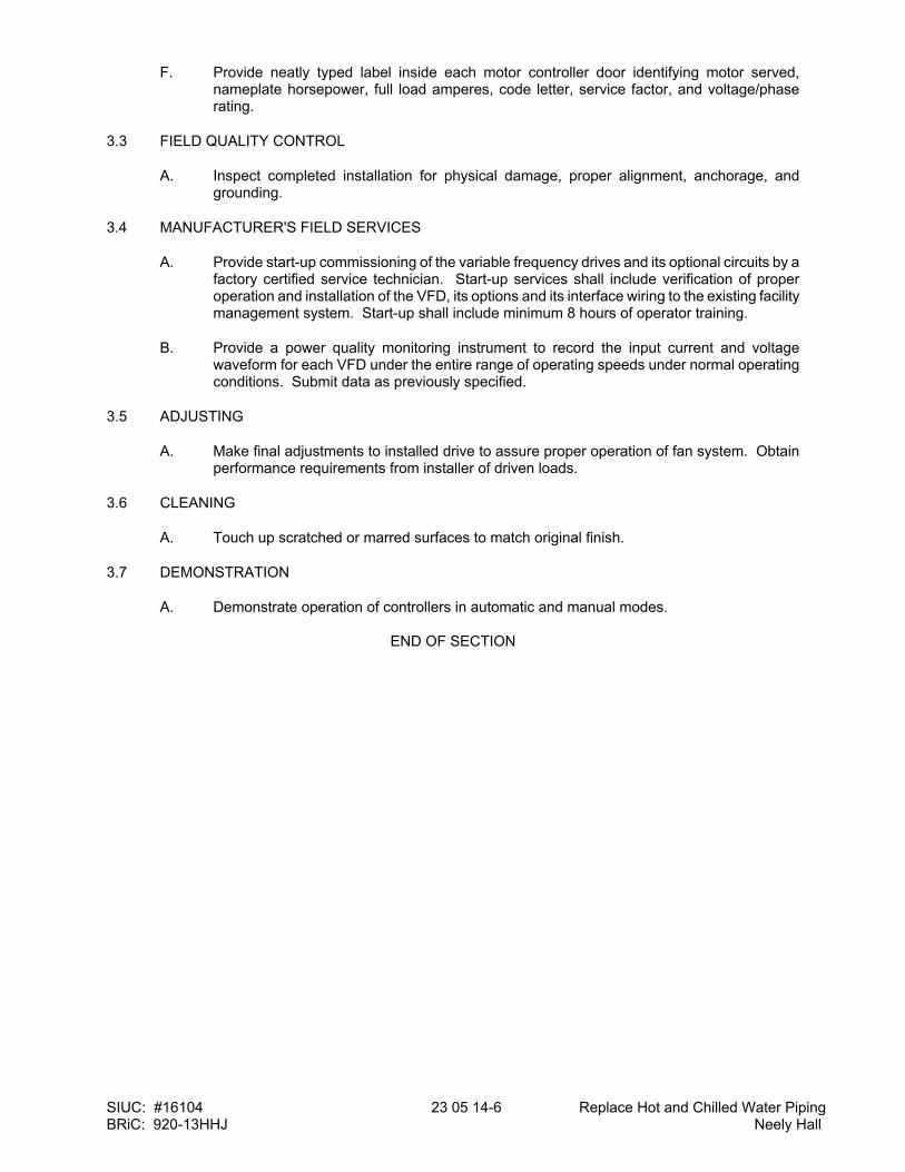
SIUC: #16104 23 05 14-6 Replace Hot and Chilled Water Piping BRiC: 920-13HHJ Neely Hall
F. Provide neatly typed label inside each motor controller door identifying motor served, nameplate horsepower, full load amperes, code letter, service factor, and voltage/phase rating.
3.3 FIELD QUALITY CONTROL
A. Inspect completed installation for physical damage, proper alignment, anchorage, and grounding.
3.4 MANUFACTURER'S FIELD SERVICES
A. Provide start-up commissioning of the variable frequency drives and its optional circuits by a factory certified service technician. Start-up services shall include verification of proper operation and installation of the VFD, its options and its interface wiring to the existing facility management system. Start-up shall include minimum 8 hours of operator training.
B. Provide a power quality monitoring instrument to record the input current and voltage waveform for each VFD under the entire range of operating speeds under normal operating conditions. Submit data as previously specified.
3.5 ADJUSTING
A. Make final adjustments to installed drive to assure proper operation of fan system. Obtain performance requirements from installer of driven loads.
3.6 CLEANING
A. Touch up scratched or marred surfaces to match original finish.
3.7 DEMONSTRATION
A. Demonstrate operation of controllers in automatic and manual modes.
END OF SECTION
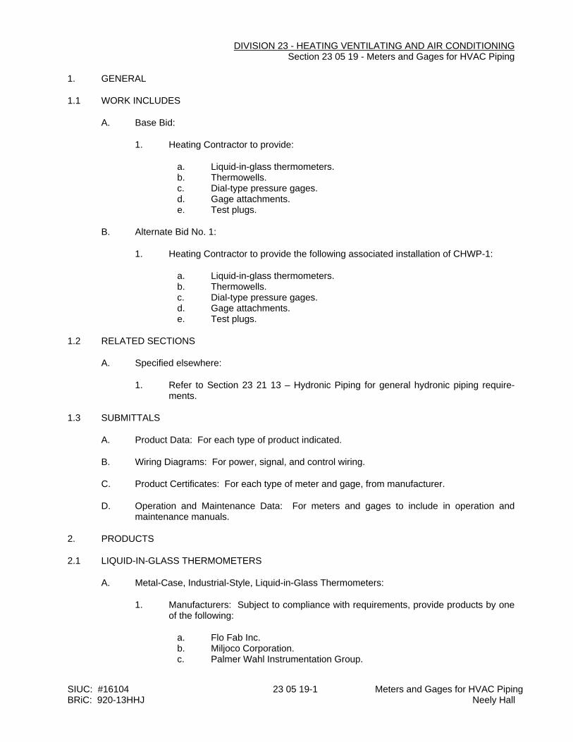
SIUC: #16104 23 05 19-1 Meters and Gages for HVAC Piping BRiC: 920-13HHJ Neely Hall
DIVISION 23 - HEATING VENTILATING AND AIR CONDITIONING Section 23 05 19 - Meters and Gages for HVAC Piping
1. GENERAL
1.1 WORK INCLUDES
A. Base Bid:
1. Heating Contractor to provide:
a. Liquid-in-glass thermometers. b. Thermowells. c. Dial-type pressure gages. d. Gage attachments. e. Test plugs.
B. Alternate Bid No. 1:
1. Heating Contractor to provide the following associated installation of CHWP-1:
a. Liquid-in-glass thermometers. b. Thermowells. c. Dial-type pressure gages. d. Gage attachments. e. Test plugs.
1.2 RELATED SECTIONS
A. Specified elsewhere:
1. Refer to Section 23 21 13 – Hydronic Piping for general hydronic piping require-ments.
1.3 SUBMITTALS
A. Product Data: For each type of product indicated.
B. Wiring Diagrams: For power, signal, and control wiring.
C. Product Certificates: For each type of meter and gage, from manufacturer.
D. Operation and Maintenance Data: For meters and gages to include in operation and maintenance manuals.
2. PRODUCTS
2.1 LIQUID-IN-GLASS THERMOMETERS
A. Metal-Case, Industrial-Style, Liquid-in-Glass Thermometers:
1. Manufacturers: Subject to compliance with requirements, provide products by one of the following:
a. Flo Fab Inc. b. Miljoco Corporation. c. Palmer Wahl Instrumentation Group.
SIUC: #16104 23 05 19-2 Meters and Gages for HVAC Piping BRiC: 920-13HHJ Neely Hall
d. Tel-Tru Manufacturing Company. e. Trerice, H. O. Co. f. Weiss Instruments, Inc. g. Winters Instruments - U.S.
2. Standard: ASME B40.200. 3. Case: Cast aluminum; 9-inch nominal size unless otherwise indicated. 4. Case Form: Adjustable angle unless otherwise indicated. 5. Tube: Glass with magnifying lens and blue or red organic liquid. 6. Tube Background: Nonreflective aluminum with permanently etched scale marings
graduated in deg F. 7. Window: Glass or plastic. 8. Stem: Aluminum and of length to suit installation.
a. Design for Thermowell Installation: Bare stem.
9. Connector: 1-1/4 inches, with ASME B1.1 screw threads. 10. Accuracy: Plus or minus 1 percent of scale range or one scale division, to a maxi-
mum of 1.5 percent of scale range.
2.2 THERMOWELLS
A. Thermowells:
1. Standard: ASME B40.200. 2. Description: Pressure-tight, socket-type fitting made for insertion into piping tee
fittng. 3. Material for Use with Copper Tubing: CNR or CUNI. 4. Material for Use with Steel Piping: CRES. 5. Type: Stepped shank unless straight or tapered shank is indicated. 6. External Threads: NPS 1/2, NPS 3/4, or NPS 1, ASME B1.20.1 pipe threads. 7. Internal Threads: 1/2, 3/4, and 1 inch, with ASME B1.1 screw threads. 8. Bore: Diameter required to match thermometer bulb or stem. 9. Insertion Length: Length required to match thermometer bulb or stem. 10. Lagging Extension: Include on thermowells for insulated piping and tubing. 11. Bushings: For converting size of thermowell's internal screw thread to size of
thermometer connection.
B. Heat-Transfer Medium: Mixture of graphite and glycerin.
2.3 PRESSURE GAGES
A. Direct-Mounted, Metal-Case, Dial-Type Pressure Gages:
1. Manufacturers: Subject to compliance with requirements, provide products by one of the following:
a. AMETEK, Inc.; U.S. Gauge. b. Ashcroft Inc. c. Ernst Flow Industries. d. Flo Fab Inc. e. Marsh Bellofram. f. Miljoco Corporation. g. Noshok. h. Palmer Wahl Instrumentation Group. i. REOTEMP Instrument Corporation. j. Tel-Tru Manufacturing Company. k. Trerice, H. O. Co.
SIUC: #16104 23 05 19-3 Meters and Gages for HVAC Piping BRiC: 920-13HHJ Neely Hall
l. Watts Regulator Co.; a div. of Watts Water Technologies, Inc. m. Weiss Instruments, Inc. n. WIKA Instrument Corporation - USA. o. Winters Instruments - U.S.
2. Standard: ASME B40.100. 3. Case: Liquid-filled Sealed type(s); cast aluminum or drawn steel; 4-1/2-inch nomi-
nal diameter. 4. Pressure-Element Assembly: Bourdon tube unless otherwise indicated. 5. Pressure Connection: Brass, with NPS 1/4 or NPS 1/2, ASME B1.20.1 pipe
threads and bottom-outlet type unless back-outlet type is indicated. 6. Movement: Mechanical, with link to pressure element and connection to pointer. 7. Dial: Nonreflective aluminum with permanently etched scale markings graduated
in psi. 8. Pointer: Dark-colored metal. 9. Window: Glass or plastic. 10. Ring: Metal. 11. Accuracy: Grade A, plus or minus 1 percent of middle half of scale range.
2.4 GAGE ATTACHMENTS
A. Snubbers: ASME B40.100, brass; with NPS 1/4 or NPS 1/2, ASME B1.20.1 pipe threads and porous-metal-type surge-dampening device. Include extension for use on insulated piping.
B. Siphons: Loop-shaped section of brass pipe with NPS 1/4 or NPS 1/2 pipe threads.
C. Valves: Brass ball, with NPS 1/4 or NPS 1/2, ASME B1.20.1 pipe threads.
2.5 TEST PLUGS
A. Manufacturers: Subject to compliance with requirements, provide products by one of the following:
1. Flow Design, Inc. 2. Miljoco Corporation. 3. National Meter, Inc. 4. Peterson Equipment Co., Inc. 5. Sisco Manufacturing Company, Inc. 6. Trerice, H. O. Co. 7. Watts Regulator Co.; a div. of Watts Water Technologies, Inc. 8. Weiss Instruments, Inc.
B. Description: Test-station fitting made for insertion into piping tee fitting.
C. Body: Brass or stainless steel with core inserts and gasketed and threaded cap. Include extended stem on units to be installed in insulated piping.
D. Thread Size: NPS 1/4 or NPS 1/2, ASME B1.20.1 pipe thread.
E. Minimum Pressure and Temperature Rating: 500 psig at 200 deg F.
F. Core Inserts: Chlorosulfonated polyethylene synthetic and EPDM self-sealing rubber.
3. EXECUTION
3.1 INSTALLATION
SIUC: #16104 23 05 19-4 Meters and Gages for HVAC Piping BRiC: 920-13HHJ Neely Hall
A. Install thermowells with socket extending to center of pipe and in vertical position in piping tees.
B. Install thermowells of sizes required to match thermometer connectors. Include bushings if required to match sizes.
C. Install thermowells with extension on insulated piping.
D. Fill thermowells with heat-transfer medium.
E. Install direct-mounted thermometers in thermowells and adjust vertical and tilted positions.
F. Install direct-mounted pressure gages in piping tees with pressure gage located on pipe at the most readable position.
G. Install valve and snubber in piping for each pressure gage for fluids (except steam).
H. Install valve and syphon fitting in piping for each pressure gage for steam.
I. Install test plugs in piping tees.
J. Install flow indicators in piping systems in accessible positions for easy viewing.
K. Assemble and install connections, tubing, and accessories between flow-measuring elements and flowmeters according to manufacturer's written instructions.
L. Install permanent indicators on walls or brackets in accessible and readable positions.
M. Install connection fittings in accessible locations for attachment to portable indicators.
N. Install thermometers in locations indicated on drawings.
O. Install pressure gages in the following locations:
1. Suction and discharge of each pump.
3.2 CONNECTIONS
A. Install meters and gages adjacent to machines and equipment to allow service and maintenance of meters, gages, machines, and equipment.
3.3 ADJUSTING
A. After installation, calibrate meters according to manufacturer's written instructions.
B. Adjust faces of meters and gages to proper angle for best visibility.
3.4 THERMOMETER SCALE-RANGE SCHEDULE
A. Scale Range for Chilled-Water Piping: 0 to 100 deg F.
B. Scale Range for Heating, Hot-Water Piping: 0 to 250 deg F.
3.5 PRESSURE-GAGE SCALE-RANGE SCHEDULE
C. Scale Range for Chilled-Water Piping: 0 to 100 psi.
SIUC: #16104 23 05 19-5 Meters and Gages for HVAC Piping BRiC: 920-13HHJ Neely Hall
D. Scale Range for Heating, Hot-Water Piping: 0 to 100 psi.
END OF SECTION
SIUC: #16104 23 05 23-1 Replace Hot and Chilled Water Piping BRiC: 920-13HHJ Neely Hall
DIVISION 23 - HEATING VENTILATING AND AIR CONDITIONING Section 23 05 23 - General-Duty Valves for HVAC Piping
1. GENERAL
1.1 WORK INCLUDES
A. Base Bid:
1. Heating Contractor Provide:
a. Bronze ball valves. b. Iron ball valves. c. Bronze swing check valves. d. Iron swing check valves.
B. Alternate Bid No. 1:
1. Heating Contractor Provide valves associated with the installation of CHWP-1:
a. Bronze ball valves. b. Iron ball valves. c. Bronze swing check valves. d. Iron swing check valves.
1.2 RELATED WORK
A. Specified elsewhere:
1. Refer to Section 23 05 53 "Identification for HVAC Piping and Equipment" for valve tags and schedules.
1.3 DEFINITIONS
A. CWP: Cold working pressure.
B. EPDM: Ethylene propylene copolymer rubber.
C. NBR: Acrylonitrile-butadiene, Buna-N, or nitrile rubber.
D. NRS: Nonrising stem.
E. OS&Y: Outside screw and yoke.
F. RS: Rising stem.
G. SWP: Steam working pressure.
1.4 SUBMITTALS
A. Product Data: For each type of valve indicated.
1.5 QUALITY ASSURANCE
A. Source Limitations for Valves: Obtain each type of valve from single source from single
SIUC: #16104 23 05 23-2 Replace Hot and Chilled Water Piping BRiC: 920-13HHJ Neely Hall
manufacturer.
B. ASME Compliance:
1. ASME B16.10 and ASME B16.34 for ferrous valve dimensions and design criteria. 2. ASME B31.1 for power piping valves. 3. ASME B31.9 for building services piping valves.
1.6 DELIVERY, STORAGE, AND HANDLING
A. Prepare valves for shipping as follows:
1. Protect internal parts against rust and corrosion. 2. Protect threads, flange faces, grooves, and weld ends. 3. Set angle, gate, and globe valves closed to prevent rattling. 4. Set ball and plug valves open to minimize exposure of functional surfaces. 5. Set butterfly valves closed or slightly open. 6. Block check valves in either closed or open position.
B. Use the following precautions during storage:
1. Maintain valve end protection. 2. Store valves indoors and maintain at higher than ambient dew point temperature. If
outdoor storage is necessary, store valves off the ground in watertight enclosures.
C. Use sling to handle large valves; rig sling to avoid damage to exposed parts. Do not use handwheels or stems as lifting or rigging points.
2. PRODUCTS
2.1 GENERAL REQUIREMENTS FOR VALVES
A. Refer to HVAC valve schedule articles for applications of valves.
B. Valve Pressure and Temperature Ratings: Not less than indicated and as required for system pressures and temperatures.
C. Valve Sizes: Same as upstream piping unless otherwise indicated.
D. Valve Actuator Types:
1. Gear Actuator: For quarter-turn valves NPS 8 and larger. 2. Handwheel: For valves other than quarter-turn types. 3. Handlever: For quarter-turn valves NPS 6 and smaller.
E. Valves in Insulated Piping: With 2-inch stem extensions and the following features:
1. Gate Valves: With rising stem. 2. Ball Valves: With extended operating handle of non-thermal-conductive material, and
protective sleeve that allows operation of valve without breaking the vapor seal or disturbing insulation.
3. Butterfly Valves: With extended neck.
F. Valve-End Connections:
SIUC: #16104 23 05 23-3 Replace Hot and Chilled Water Piping BRiC: 920-13HHJ Neely Hall
1. Flanged: With flanges according to ASME B16.1 for iron valves. 2. Solder Joint: With sockets according to ASME B16.18. 3. Threaded: With threads according to ASME B1.20.1.
G. Valve Bypass and Drain Connections: MSS SP-45.
2.2 BRONZE BALL VALVES
A. Two-Piece, Regular-Port, Bronze Ball Valves with Bronze Trim:
1. Manufacturers: Subject to compliance with requirements, provide products by one of the following:
a. American Valve, Inc. b. Conbraco Industries, Inc.; Apollo Valves. c. Crane Co.; Crane Valve Group; Jenkins Valves. d. Crane Co.; Crane Valve Group; Stockham Division. e. DynaQuip Controls. f. Hammond Valve. g. Lance Valves; a division of Advanced Thermal Systems, Inc. h. Milwaukee Valve Company. i. NIBCO INC.
2. Description:
a. Standard: MSS SP-110. b. SWP Rating: 150 psig. c. CWP Rating: 600 psig. d. Body Design: Two piece. e. Body Material: Bronze. f. Ends: Threaded. g. Seats: PTFE or TFE. h. Stem: Bronze. i. Ball: Chrome-plated brass. j. Port: Regular.
2.3 IRON BALL VALVES
A. Class 125, Iron Ball Valves:
1. See Editing Instruction No. 1 in the Evaluations for cautions about naming manufacturers. See Division 1 Section "Product Requirements."
2. Manufacturers: Subject to compliance with requirements,
a. American Valve, Inc. b. Conbraco Industries, Inc.; Apollo Valves. c. Watts Regulator Co.; a division of Watts Water Technologies, Inc.
3. Description:
a. Standard: MSS SP-72. b. CWP Rating: 200 psig. c. Body Design: Split body. d. Body Material: ASTM A 126, gray iron. e. Ends: Flanged.
SIUC: #16104 23 05 23-4 Replace Hot and Chilled Water Piping BRiC: 920-13HHJ Neely Hall
f. Seats: PTFE or TFE. g. Stem: Stainless steel. h. Ball: Stainless steel. i. Port: Full.
2.4 IRON, SINGLE-FLANGE BUTTERFLY VALVES
A. 200 CWP, Iron, Single-Flange Butterfly Valves with EPDM Seat and Stainless-Steel Disc:
1. Manufacturers: Subject to compliance with requirements, provide products by one of the following:
a. American Valve, Inc. b. Conbraco Industries, Inc.; Apollo Valves. c. Cooper Cameron Valves; a division of Cooper Cameron Corp. d. Crane Co.; Crane Valve Group; Jenkins Valves. e. Crane Co.; Crane Valve Group; Stockham Division. f. Flo Fab Inc. g. Hammond Valve. h. Kitz Corporation. i. Legend Valve. j. Milwaukee Valve Company. k. Mueller Steam Specialty; a division of SPX Corporation. l. NIBCO INC. m. Norriseal; a Dover Corporation company. n. Red-White Valve Corporation. o. Spence Strainers International; a division of CIRCOR International. p. Sure Flow Equipment Inc. q. Watts Regulator Co.; a division of Watts Water Technologies, Inc.
2. Description:
a. Standard: MSS SP-67, Type I. b. CWP Rating: 200 psig. c. Body Design: Lug type; suitable for bidirectional dead-end service at rated
pressure without use of downstream flange. d. Body Material: ASTM A 126, cast iron or ASTM A 536, ductile iron. e. Seat: EPDM. f. Stem: One- or two-piece stainless steel. g. Disc: Stainless steel.
2.5 BRONZE SWING CHECK VALVES
A. Class 150, Bronze Swing Check Valves with Bronze Disc:
1. Manufacturers: Subject to compliance with requirements, provide products by one of the following:
a. American Valve, Inc. b. Crane Co.; Crane Valve Group; Crane Valves. c. Crane Co.; Crane Valve Group; Jenkins Valves. d. Crane Co.; Crane Valve Group; Stockham Division. e. Kitz Corporation. f. Milwaukee Valve Company.
SIUC: #16104 23 05 23-5 Replace Hot and Chilled Water Piping BRiC: 920-13HHJ Neely Hall
g. NIBCO INC. h. Red-White Valve Corporation. i. Zy-Tech Global Industries, Inc.
2. Description:
a. Standard: MSS SP-80, Type 3. b. CWP Rating: 300 psig. c. Body Design: Horizontal flow. d. Body Material: ASTM B 62, bronze. e. Ends: Threaded. f. Disc: Bronze.
2.6 IRON SWING CHECK VALVES
A. Class 125, Iron Swing Check Valves with Metal Seats:
1. Manufacturers: Subject to compliance with requirements, provide products by one of the following:
a. Crane Co.; Crane Valve Group; Crane Valves. b. Crane Co.; Crane Valve Group; Jenkins Valves. c. Crane Co.; Crane Valve Group; Stockham Division. d. Hammond Valve. e. Kitz Corporation. f. Legend Valve. g. Milwaukee Valve Company. h. NIBCO INC. i. Powell Valves. j. Red-White Valve Corporation. k. Sure Flow Equipment Inc. l. Watts Regulator Co.; a division of Watts Water Technologies, Inc. m. Zy-Tech Global Industries, Inc.
2. Description:
a. Standard: MSS SP-71, Type I. b. NPS 2-1/2 to NPS 12, CWP Rating: 200 psig. c. NPS 14 to NPS 24, CWP Rating: 150 psig. d. Body Design: Clear or full waterway. e. Body Material: ASTM A 126, gray iron with bolted bonnet. f. Ends: Flanged. g. Trim: Bronze. h. Gasket: Asbestos free.
2.7 BRONZE GLOBE VALVES
A. Class 150, Bronze Globe Valves with Bronze Disc:
1. Manufacturers: Subject to compliance with requirements, provide products by one of the following:
a. Crane Co.; Crane Valve Group; Crane Valves. b. Hammond Valve. c. Kitz Corporation.
SIUC: #16104 23 05 23-6 Replace Hot and Chilled Water Piping BRiC: 920-13HHJ Neely Hall
d. Milwaukee Valve Company. e. NIBCO INC. f. Powell Valves. g. Red-White Valve Corporation. h. Watts Regulator Co.; a division of Watts Water Technologies, Inc. i. Zy-Tech Global Industries, Inc.
2. Description:
a. Standard: MSS SP-80, Type 2. b. CWP Rating: 300 psig. c. Body Material: ASTM B 62, bronze with integral seat and union-ring bonnet. d. Ends: Threaded. e. Stem: Bronze. f. Disc: Bronze. g. Packing: Asbestos free. h. Handwheel: Malleable iron, bronze, or aluminum.
2.8 IRON GLOBE VALVES
A. Class 125, Iron Globe Valves:
1. Manufacturers: Subject to compliance with requirements, provide products by one of the following:
a. Crane Co.; Crane Valve Group; Crane Valves. b. Crane Co.; Crane Valve Group; Jenkins Valves. c. Crane Co.; Crane Valve Group; Stockham Division. d. Hammond Valve. e. Kitz Corporation. f. Milwaukee Valve Company. g. NIBCO INC. h. Powell Valves. i. Red-White Valve Corporation. j. Watts Regulator Co.; a division of Watts Water Technologies, Inc. k. Zy-Tech Global Industries, Inc.
2. Description:
a. Standard: MSS SP-85, Type I. b. CWP Rating: 200 psig. c. Body Material: ASTM A 126, gray iron with bolted bonnet. d. Ends: Flanged. e. Trim: Bronze. f. Packing and Gasket: Asbestos free.
B. Class 250, Iron Globe Valves:
1. Manufacturers: Subject to compliance with requirements, provide products by one of the following:
a. Crane Co.; Crane Valve Group; Crane Valves. b. Crane Co.; Crane Valve Group; Jenkins Valves. c. Crane Co.; Crane Valve Group; Stockham Division. d. Hammond Valve.
SIUC: #16104 23 05 23-7 Replace Hot and Chilled Water Piping BRiC: 920-13HHJ Neely Hall
e. Milwaukee Valve Company. f. NIBCO INC. g. Watts Regulator Co.; a division of Watts Water Technologies, Inc.
2. Description:
a. Standard: MSS SP-85, Type I. b. CWP Rating: 500 psig. c. Body Material: ASTM A 126, gray iron with bolted bonnet. d. Ends: Flanged. e. Trim: Bronze. f. Packing and Gasket: Asbestos free.
3. EXECUTION
3.1 EXAMINATION
A. Examine valve interior for cleanliness, freedom from foreign matter, and corrosion. Remove special packing materials, such as blocks, used to prevent disc movement during shipping and handling.
B. Operate valves in positions from fully open to fully closed. Examine guides and seats made accessible by such operations.
C. Examine threads on valve and mating pipe for form and cleanliness.
D. Examine mating flange faces for conditions that might cause leakage. Check bolting for proper size, length, and material. Verify that gasket is of proper size, that its material composition is suitable for service, and that it is free from defects and damage.
E. Do not attempt to repair defective valves; replace with new valves.
3.2 VALVE INSTALLATION
A. Install valves with unions or flanges at each piece of equipment arranged to allow service, maintenance, and equipment removal without system shutdown.
B. Locate valves for easy access and provide separate support where necessary.
C. Install valves in horizontal piping with stem at or above center of pipe.
D. Install valves in position to allow full stem movement.
E. Install check valves for proper direction of flow and as follows:
1. Swing Check Valves: In horizontal position with hinge pin level.
3.3 ADJUSTING
A. Adjust or replace valve packing after piping systems have been tested and put into service but before final adjusting and balancing. Replace valves if persistent leaking occurs.
3.4 CHILLED-WATER VALVE SCHEDULE
A. Pipe NPS 2-1/2 and Larger:
SIUC: #16104 23 05 23-8 Replace Hot and Chilled Water Piping BRiC: 920-13HHJ Neely Hall
1. Iron Ball Valves, NPS 2-1/2 to NPS 10: Class 150.
3.5 HEATING-WATER VALVE SCHEDULE
A. Pipe NPS 2 and Smaller:
1. Ball Valves: Two piece, regular port, bronze with bronze trim.
B. Pipe NPS 2-1/2 and Larger:
1. Iron Ball Valves, NPS 2-1/2 to NPS 10: Class 150.
END OF SECTION
SIUC: #16104 23 05 29-1 Replace Hot and Chilled Water Piping BRiC: 920-13HHJ Neely Hall
DIVISION 23 - HEATING VENTILATING AND AIR CONDITIONING Section 23 05 29 - Hangers and Supports For HVAC Piping and Equipment
1. GENERAL
1.1 WORK INCLUDES
A. Base Bid:
1. Heating Contractor provide the following hangers and supports for HVAC system piping and equipment:
a. Steel pipe hangers and supports. b. Trapeze pipe hangers. c. Metal framing systems. d. Fastener systems. e. Equipment supports.
B. Alternate Bid No. 1:
1. Heating Contractor provide hangers and supports for CHWP-1 and associated piping.
1.2 RELATED SECTIONS
A. Section 230548 – Seismic Contols for HVAC Piping and Equipment.
1.3 DEFINITIONS
A. MSS: Manufacturers Standardization Society for The Valve and Fittings Industry Inc.
B. Terminology: As defined in MSS SP-90, "Guidelines on Terminology for Pipe Hangers and Supports."
1.4 PERFORMANCE REQUIREMENTS
A. Design supports for multiple pipes, including pipe stands, capable of supporting combined weight of supported systems, system contents, and test water.
B. Design equipment supports capable of supporting combined operating weight of supported equipment and connected systems and components.
1.5 SUBMITTALS
A. Product Data: For the following:
1. Steel pipe hangers and supports. 2. Powder-actuated fastener systems.
B. Shop Drawings: Show fabrication and installation details and include calculations for the following:
1. Trapeze pipe hangers. Include Product Data for components. 2. Metal framing systems. Include Product Data for components. 3. Pipe stands. Include Product Data for components. 4. Equipment supports.
C. Welding certificates.
SIUC: #16104 23 05 29-2 Replace Hot and Chilled Water Piping BRiC: 920-13HHJ Neely Hall
2. PRODUCTS
2.1 MANUFACTURERS
A. In other Part 2 articles where titles below introduce lists, the following requirements apply to product selection:
1. Manufacturers: Subject to compliance with requirements, provide products by one of the manufacturers specified.
2.2 STEEL PIPE HANGERS AND SUPPORTS
A. Description: MSS SP-58, Types 1 through 58, factory-fabricated components. Refer to Part 3 "Hanger and Support Applications" Article for where to use specific hanger and support types.
B. Manufacturers:
1. AAA Technology & Specialties Co., Inc. 2. Bergen-Power Pipe Supports. 3. B-Line Systems, Inc.; a division of Cooper Industries. 4. Carpenter & Paterson, Inc. 5. Empire Industries, Inc. 6. ERICO/Michigan Hanger Co. 7. Globe Pipe Hanger Products, Inc. 8. Grinnell Corp. 9. GS Metals Corp. 10. National Pipe Hanger Corporation. 11. PHD Manufacturing, Inc. 12. PHS Industries, Inc. 13. Piping Technology & Products, Inc. 14. Tolco Inc.
C. Galvanized, Metallic Coatings: Pregalvanized or hot dipped.
D. Nonmetallic Coatings: Plastic coating, jacket, or liner.
E. Padded Hangers: Hanger with fiberglass or other pipe insulation pad or cushion for support of bearing surface of piping.
2.3 TRAPEZE PIPE HANGERS
A. Description: MSS SP-69, Type 59, shop- or field-fabricated pipe-support assembly made from structural-steel shapes with MSS SP-58 hanger rods, nuts, saddles, and U-bolts.
2.4 METAL FRAMING SYSTEMS
A. Description: MFMA-3, shop- or field-fabricated pipe-support assembly made of steel channels and other components.
B. Manufacturers:
1. B-Line Systems, Inc.; a division of Cooper Industries. 2. ERICO/Michigan Hanger Co.; ERISTRUT Div. 3. GS Metals Corp. 4. Power-Strut Div.; Tyco International, Ltd. 5. Thomas & Betts Corporation. 6. Tolco Inc. 7. Unistrut Corp.; Tyco International, Ltd.
SIUC: #16104 23 05 29-3 Replace Hot and Chilled Water Piping BRiC: 920-13HHJ Neely Hall
C. Coatings: Manufacturer's standard finish, unless bare metal surfaces are indicated.
D. Nonmetallic Coatings: Plastic coating, jacket, or liner.
2.5 FASTENER SYSTEMS
A. Powder-Actuated Fasteners: Threaded-steel stud, for use in hardened portland cement concrete with pull-out, tension, and shear capacities appropriate for supported loads and building materials where used.
1. Manufacturers:
a. Hilti, Inc. b. ITW Ramset/Red Head. c. Masterset Fastening Systems, Inc. d. MKT Fastening, LLC. e. Powers Fasteners.
B. Mechanical-Expansion Anchors: Insert-wedge-type zinc-coated steel, for use in hardened portland cement concrete with pull-out, tension, and shear capacities appropriate for supported loads and building materials where used.
1. Manufacturers:
a. B-Line Systems, Inc.; a division of Cooper Industries. b. Empire Industries, Inc. c. Hilti, Inc. d. ITW Ramset/Red Head. e. MKT Fastening, LLC. f. Powers Fasteners.
2.6 EQUIPMENT SUPPORTS
A. Description: Welded, shop- or field-fabricated equipment support made from structural-steel shapes.
2.7 MISCELLANEOUS MATERIALS
A. Structural Steel: ASTM A 36/A 36M, steel plates, shapes, and bars; black and galvanized.
B. Grout: ASTM C 1107, factory-mixed and -packaged, dry, hydraulic-cement, nonshrink and nonmetallic grout; suitable for interior and exterior applications.
1. Properties: Nonstaining, noncorrosive, and nongaseous. 2. Design Mix: 5000-psi, 28-day compressive strength.
3. EXECUTION
3.1 HANGER AND SUPPORT APPLICATIONS
A. Specific hanger and support requirements are specified in Sections specifying piping systems and equipment.
B. Comply with MSS SP-69 for pipe hanger selections and applications that are not specified in piping system Sections.
C. Use hangers and supports with galvanized, metallic coatings for piping and equipment that will not have field-applied finish.

SIUC: #16104 23 05 29-4 Replace Hot and Chilled Water Piping BRiC: 920-13HHJ Neely Hall
D. Use nonmetallic coatings on attachments for electrolytic protection where attachments are in direct contact with copper tubing.
E. Use padded hangers for piping that is subject to scratching.
F. Horizontal-Piping Hangers and Supports: Unless otherwise indicated and except as specified in piping system Sections, install the following types:
1. Adjustable, Steel Clevis Hangers (MSS Type 1): For suspension of noninsulated or insulated stationary pipes, NPS 1/2 to NPS 30.
2. Yoke-Type Pipe Clamps (MSS Type 2): For suspension of 120 to 450 deg F pipes, NPS 4 to NPS 16, requiring up to 4 inches of insulation.
3. Carbon- or Alloy-Steel, Double-Bolt Pipe Clamps (MSS Type 3): For suspension of pipes, NPS 3/4 to NPS 24, requiring clamp flexibility and up to 4 inches of insulation.
4. Steel Pipe Clamps (MSS Type 4): For suspension of cold and hot pipes, NPS 1/2 to NPS 24, if little or no insulation is required.
5. Pipe Hangers (MSS Type 5): For suspension of pipes, NPS 1/2 to NPS 4, to allow off-center closure for hanger installation before pipe erection.
6. Adjustable, Swivel Split- or Solid-Ring Hangers (MSS Type 6): For suspension of noninsulated stationary pipes, NPS 3/4 to NPS 8.
7. Adjustable, Steel Band Hangers (MSS Type 7): For suspension of noninsulated stationary pipes, NPS 1/2 to NPS 8.
8. Adjustable Band Hangers (MSS Type 9): For suspension of noninsulated stationary pipes, NPS 1/2 to NPS 8.
9. Adjustable, Swivel-Ring Band Hangers (MSS Type 10): For suspension of noninsulated stationary pipes, NPS 1/2 to NPS 2.
10. Split Pipe-Ring with or without Turnbuckle-Adjustment Hangers (MSS Type 11): For suspension of noninsulated stationary pipes, NPS 3/8 to NPS 8.
11. Extension Hinged or 2-Bolt Split Pipe Clamps (MSS Type 12): For suspension of noninsulated stationary pipes, NPS 3/8 to NPS 3.
12. U-Bolts (MSS Type 24): For support of heavy pipes, NPS 1/2 to NPS 30. 13. Clips (MSS Type 26): For support of insulated pipes not subject to expansion or
contraction. 14. Pipe Saddle Supports (MSS Type 36): For support of pipes, NPS 4 to NPS 36,
with steel pipe base stanchion support and cast-iron floor flange. 15. Pipe Stanchion Saddles (MSS Type 37): For support of pipes, NPS 4 to NPS 36,
with steel pipe base stanchion support and cast-iron floor flange and with U-bolt to retain pipe.
16. Adjustable, Pipe Saddle Supports (MSS Type 38): For stanchion-type support for pipes, NPS 2-1/2 to NPS 36, if vertical adjustment is required, with steel pipe base stanchion support and cast-iron floor flange.
17. Single Pipe Rolls (MSS Type 41): For suspension of pipes, NPS 1 to NPS 30, from 2 rods if longitudinal movement caused by expansion and contraction might occur.
18. Adjustable Roller Hangers (MSS Type 43): For suspension of pipes, NPS 2-1/2 to NPS 20, from single rod if horizontal movement caused by expansion and contraction might occur.
19. Complete Pipe Rolls (MSS Type 44): For support of pipes, NPS 2 to NPS 42, if longitudinal movement caused by expansion and contraction might occur but vertical adjustment is not necessary.
20. Pipe Roll and Plate Units (MSS Type 45): For support of pipes, NPS 2 to NPS 24, if small horizontal movement caused by expansion and contraction might occur and vertical adjustment is not necessary.
21. Adjustable Pipe Roll and Base Units (MSS Type 46): For support of pipes, NPS 2 to NPS 30, if vertical and lateral adjustment during installation might be required in addition to expansion and contraction.
G. Vertical-Piping Clamps: Unless otherwise indicated and except as specified in piping system Sections, install the following types:
SIUC: #16104 23 05 29-5 Replace Hot and Chilled Water Piping BRiC: 920-13HHJ Neely Hall
1. Extension Pipe or Riser Clamps (MSS Type 8): For support of pipe risers, NPS 3/4 to NPS 20.
2. Carbon- or Alloy-Steel Riser Clamps (MSS Type 42): For support of pipe risers, NPS 3/4 to NPS 20, if longer ends are required for riser clamps.
H. Hanger-Rod Attachments: Unless otherwise indicated and except as specified in piping system Sections, install the following types:
1. Steel Turnbuckles (MSS Type 13): For adjustment up to 6 inches for heavy loads.
2. Steel Clevises (MSS Type 14): For 120 to 450 deg F piping installations. 3. Swivel Turnbuckles (MSS Type 15): For use with MSS Type 11, split pipe rings. 4. Malleable-Iron Sockets (MSS Type 16): For attaching hanger rods to various
types of building attachments. 5. Steel Weldless Eye Nuts (MSS Type 17): For 120 to 450 deg F piping
installations.
I. Building Attachments: Unless otherwise indicated and except as specified in piping system Sections, install the following types:
1. Steel or Malleable Concrete Inserts (MSS Type 18): For upper attachment to suspend pipe hangers from concrete ceiling.
2. Top-Beam C-Clamps (MSS Type 19): For use under roof installations with bar-joist construction to attach to top flange of structural shape.
3. Side-Beam or Channel Clamps (MSS Type 20): For attaching to bottom flange of beams, channels, or angles.
4. Center-Beam Clamps (MSS Type 21): For attaching to center of bottom flange of beams.
5. Welded Beam Attachments (MSS Type 22): For attaching to bottom of beams if loads are considerable and rod sizes are large.
6. C-Clamps (MSS Type 23): For structural shapes. 7. Top-Beam Clamps (MSS Type 25): For top of beams if hanger rod is required
tangent to flange edge. 8. Side-Beam Clamps (MSS Type 27): For bottom of steel I-beams. 9. Steel-Beam Clamps with Eye Nuts (MSS Type 28): For attaching to bottom of
steel I-beams for heavy loads. 10. Linked-Steel Clamps with Eye Nuts (MSS Type 29): For attaching to bottom of
steel I-beams for heavy loads, with link extensions. 11. Malleable Beam Clamps with Extension Pieces (MSS Type 30): For attaching to
structural steel. 12. Welded-Steel Brackets: For support of pipes from below, or for suspending from
above by using clip and rod. Use one of the following for indicated loads:
a. Light (MSS Type 31): 750 lb. b. Medium (MSS Type 32): 1500 lb. c. Heavy (MSS Type 33): 3000 lb.
13. Side-Beam Brackets (MSS Type 34): For sides of steel or wooden beams. 14. Plate Lugs (MSS Type 57): For attaching to steel beams if flexibility at beam is
required. 15. Horizontal Travelers (MSS Type 58): For supporting piping systems subject to
linear horizontal movement where headroom is limited.
J. Saddles and Shields: Unless otherwise indicated and except as specified in piping system Sections, install the following types:
1. Steel Pipe-Covering Protection Saddles (MSS Type 39): To fill interior voids with insulation that matches adjoining insulation.
SIUC: #16104 23 05 29-6 Replace Hot and Chilled Water Piping BRiC: 920-13HHJ Neely Hall
2. Protection Shields (MSS Type 40): Of length recommended in writing by manufacturer to prevent crushing insulation.
3. Thermal-Hanger Shield Inserts: For supporting insulated pipe.
K. Comply with MSS SP-69 for trapeze pipe hanger selections and applications that are not specified in piping system Sections.
L. Comply with MFMA-102 for metal framing system selections and applications that are not specified in piping system Sections.
M. Use powder-actuated fasteners or mechanical-expansion anchors instead of building attachments where required in concrete construction.
3.2 HANGER AND SUPPORT INSTALLATION
A. Steel Pipe Hanger Installation: Comply with MSS SP-69 and MSS SP-89. Install hangers, supports, clamps, and attachments as required to properly support piping from building structure.
B. Trapeze Pipe Hanger Installation: Comply with MSS SP-69 and MSS SP-89. Arrange for grouping of parallel runs of horizontal piping and support together on field-fabricated trapeze pipe hangers.
1. Pipes of Various Sizes: Support together and space trapezes for smallest pipe size or install intermediate supports for smaller diameter pipes as specified above for individual pipe hangers.
2. Field fabricate from ASTM A 36/A 36M, steel shapes selected for loads being supported. Weld steel according to AWS D1.1.
C. Metal Framing System Installation: Arrange for grouping of parallel runs of piping and support together on field-assembled metal framing systems.
D. Fastener System Installation:
1. Install powder-actuated fasteners for use in lightweight concrete or concrete slabs less than 4 inches thick in concrete after concrete is placed and completely cured. Use operators that are licensed by powder-actuated tool manufacturer. Install fasteners according to powder-actuated tool manufacturer's operating manual.
2. Install mechanical-expansion anchors in concrete after concrete is placed and completely cured. Install fasteners according to manufacturer's written instructions.
E. Install hangers and supports complete with necessary inserts, bolts, rods, nuts, washers, and other accessories.
F. Equipment Support Installation: Fabricate from welded-structural-steel shapes.
G. Install hangers and supports to allow controlled thermal and seismic movement of piping systems, to permit freedom of movement between pipe anchors, and to facilitate action of expansion joints, expansion loops, expansion bends, and similar units.
H. Install lateral bracing with pipe hangers and supports to prevent swaying.
I. Install building attachments within concrete slabs or attach to structural steel. Install additional attachments at concentrated loads, including valves, flanges, and strainers, NPS 2-1/2 and larger and at changes in direction of piping. Install concrete inserts before concrete is placed; fasten inserts to forms and install reinforcing bars through openings at top of inserts.

SIUC: #16104 23 05 29-7 Replace Hot and Chilled Water Piping BRiC: 920-13HHJ Neely Hall
J. Load Distribution: Install hangers and supports so piping live and dead loads and stresses from movement will not be transmitted to connected equipment.
K. Pipe Slopes: Install hangers and supports to provide indicated pipe slopes and so maximum pipe deflections allowed by ASME B31.1 (for power piping) and ASME B31.9 (for building services piping) are not exceeded.
L. Insulated Piping: Comply with the following:
1. Attach clamps and spacers to piping.
a. Piping Operating above Ambient Air Temperature: Clamp may project through insulation.
b. Piping Operating below Ambient Air Temperature: Use thermal-hanger shield insert with clamp sized to match OD of insert.
c. Do not exceed pipe stress limits according to ASME B31.1 for power piping and ASME B31.9 for building services piping.
2. Install MSS SP-58, Type 39, protection saddles if insulation without vapor barrier is indicated. Fill interior voids with insulation that matches adjoining insulation.
3. Install MSS SP-58, Type 40, protective shields on cold piping with vapor barrier. Shields shall span an arc of 180 degrees.
4. Shield Dimensions for Pipe: Not less than the following:
a. NPS 1/4 to NPS 3-1/2: 12 inches long and 0.048 inch thick. b. NPS 4: 12 inches long and 0.06 inch thick. c. NPS 5 and NPS 6: 18 inches long and 0.06 inch thick. d. NPS 8 to NPS 14: 24 inches long and 0.075 inch thick. e. NPS 16 to NPS 24: 24 inches long and 0.105 inch thick.
5. Pipes NPS 8 and Larger: Include wood inserts. 6. Insert Material: Length at least as long as protective shield. 7. Thermal-Hanger Shields: Install with insulation same thickness as piping
insulation.
3.3 EQUIPMENT SUPPORTS
A. Fabricate structural-steel stands to suspend equipment from structure overhead or to support equipment above floor.
B. Grouting: Place grout under supports for equipment and make smooth bearing surface.
C. Provide lateral bracing, to prevent swaying, for equipment supports.
3.4 METAL FABRICATIONS
A. Cut, drill, and fit miscellaneous metal fabrications for trapeze pipe hangers and equipment supports.
B. Fit exposed connections together to form hairline joints. Field weld connections that cannot be shop welded because of shipping size limitations.
C. Field Welding: Comply with AWS D1.1 procedures for shielded metal arc welding, appearance and quality of welds, and methods used in correcting welding work, and with the following:
SIUC: #16104 23 05 29-8 Replace Hot and Chilled Water Piping BRiC: 920-13HHJ Neely Hall
1. Use materials and methods that minimize distortion and develop strength and corrosion resistance of base metals.
2. Obtain fusion without undercut or overlap. 3. Remove welding flux immediately. 4. Finish welds at exposed connections so no roughness shows after finishing and
contours of welded surfaces match adjacent contours.
3.5 ADJUSTING
A. Hanger Adjustments: Adjust hangers to distribute loads equally on attachments and to achieve indicated slope of pipe.
B. Trim excess length of continuous-thread hanger and support rods to 1-1/2 inches.
3.6 PAINTING
A. Touch Up: Clean field welds and abraded areas of shop paint. Paint exposed areas immediately after erecting hangers and supports. Use same materials as used for shop painting. Comply with SSPC-PA 1 requirements for touching up field-painted surfaces.
1. Apply paint by brush or spray to provide minimum dry film thickness of 2.0 mils.
B. Touch Up: Cleaning and touchup painting of field welds, bolted connections, and abraded areas of shop paint on miscellaneous metal are specified in Section 09 90 10.
C. Galvanized Surfaces: Clean welds, bolted connections, and abraded areas and apply galvanizing-repair paint to comply with ASTM A 780.
END OF SECTION

SIUC: #16104 23 05 48-1 Replace Hot and Chilled Water Piping BRiC: 920-13HHJ Neely Hall
DIVISION 23 - HEATING VENTILATING AND AIR CONDITIONING Section 23 05 48 - Seismic Controls for HVAC Piping and Equipment
1. GENERAL
1.1 WORK INCLUDES
A. Base Bid:
1. Heating Contractor Provide:
a. Seismic Protection for piping and equipment. b. Seismic restraints for isolated equipment. c. Seismic restraints for non-isolated equipment. d. Certification of seismic restraint designs and installation supervision.
B. Alternate Bid No. 1:
1. Heating Contractor Provide seismic protection for CHWP-1 and associated piping.
1.2 QUALITY ASSURANCE
A. Testing Agency: A/E will hire an independent testing company to test anchorage devices to restrained components. If tests fail, components will be replaced by the installing contractor (Heating or Ventilating) and additional components will be tested.
1.3 DEFINITIONS
A. Life Safety Systems:
1. All systems involved with fire protection including sprinkler piping, fire pumps, jockey pumps, fire pump control panels, service water supply piping, water tanks, fire dampers and smoke exhaust systems.
2. All systems involved with and/or connected to emergency power supply including all generators, transfer switches, transformers and all flowpaths to fire protection and/or emergency lighting systems.
3. All medical and life support systems. 4. Fresh air relief systems on emergency control sequence including air handlers,
conduit, duct, dampers, etc. 5. All life safety equipment has an asterisk on the equipment schedule.
B. Positive Attachment: A positive attachment is defined as a cast-in anchor, a drill-in wedge anchor, a double sided beam clamp loaded perpendicular to a beam, or a welded or bolted connection to structure. Single sided "C" type beam clamps for support rods of overhead piping, ductwork, fire protection, electrical conduit, bus duct, or cable trays, or any other equipment are not acceptable on this project as seismic anchor points.
C. Transverse Bracing: Restraint(s) applied to limit motion perpendicular to the centerline of the pipe, duct or conduit.
D. Longitudinal Bracing: Restraint(s) applied to limit motion parallel to the centerline of the pipe, duct or conduit.
1.4 SUBMITTALS
SIUC: #16104 23 05 48-2 Replace Hot and Chilled Water Piping BRiC: 920-13HHJ Neely Hall
A. Submit under the provisions of 01300.
B. Descriptive Data:
1. Catalog cuts or data sheets on specific restraints detailing compliance with the specification.
2. Detailed schedules of flexible and rigidly mounted equipment, showing seismic restraints by referencing numbered descriptive drawings.
C. Shop Drawings:
1. Submit fabrication details for equipment bases including dimensions, structural member sizes and support point locations.
2. Provide all details of suspension and support for ceiling hung equipment. 3. Where walls, floors, slabs or supplementary steel work are used for seismic
restraint locations, details of acceptable attachment methods for ducts, conduit and pipe must be included and approved before the condition is accepted for installation. Restraint manufacturers' submittals must include spacing, static loads and seismic loads at all attachment and support points.
4. Provide specific details of seismic restraints and anchors; include number, size and locations for each piece of equipment.
D. Seismic Certification and Analysis:
1. Seismic restraint calculations must be provided for all connections of equipment to the structure. Calculations must be stamped by a registered professional engineer with at least five years of seismic design experience, licensed in the state of the job location.
2. All restraining devices shall have a preapproval number from California OSHPD or some other recognized government agency showing maximum restraint ratings. Preapprovals based on independent testing are preferred to preapprovals based on calculations. Where pre-approved devices are not available, submittals based on independent testing are preferred. Calculations (including the combining of tensile and shear loadings) to support seismic restraint designs must be stamped by a registered professional engineer with at least five years of seismic design experience and licensed in the state of the job location. Testing and calcu lations must include both shear and tensile loads as well as one test or analysis at 45° to the weakest mode.
3. Analysis must indicate calculated dead loads, static seismic loads and capacity of materials utilized for connections to equipment and structure. Analysis must detail anchoring methods, bolt diameter, embedment and/or welded length. All seismic restraint devices shall be designed to accept, without failure, the forces detailed in section 1.9 acting through the equipment center of gravity. Overturning moments may exceed forces at ground level.
1.5 GENERAL
A. It is the intent of the seismic portion of this specification to keep all mechanical and electrical building system components in place during a seismic event.
B. All such systems must be installed in strict accordance with seismic codes, component manufacturer's and building construction standards. Whenever a conflict occurs between the manufacturer's or construction standards, the most stringent shall apply.
C. This specification is considered to be minimum requirements for seismic consideration and is not intended as a substitute for legislated, more stringent, national, state or local
SIUC: #16104 23 05 48-3 Replace Hot and Chilled Water Piping BRiC: 920-13HHJ Neely Hall
construction requirements (i.e. California Title 24, California OSHPD, Canadian Building Codes, or other requirements).
D. Any variance or non-compliance with these specification requirements shall be corrected by the contractor in an approved manner.
E. Seismic restraints shall be designed in accordance with seismic force levels as detailed in section 1.9.
1.6 REGULATION REQUIREMENTS
A. General: Comply with applicable codes pertaining to product materials and installations of seismic supports and restraints.
1.7 MANUFACTURERS RESPONSIBILITY
A. Manufacturer of seismic control equipment shall have the following responsibilities:
1. Determine seismic restraint sizes and locations. 2. Provide seismic restraints as scheduled or specified. 3. Provide calculations and materials if required for restraint of un-isolated
equipment. 4. Provide installation instructions, drawings and trained field supervision to insure
proper installation and performance.
1.8 RELATED WORK
A. Housekeeping Pads:
1. Housekeeping pad reinforcement and monolithic pad attachment to the structure details and design shall be prepared by the restraint vendor if not already indicated on the drawings.
2. Housekeeping pads shall be coordinated with restraint vendor and sized to provide a minimum edge distance of ten (10) bolt diameters all around the outermost anchor bolt to allow development of full drill-in wedge anchor ratings. If cast-in anchors are to be used, the housekeeping pads shall be sized to accommodate the ACI requirements for bolt coverage and embedment.
B. Supplementary Support Steel: Contractor shall supply supplementary support steel for all equipment, piping, ductwork, etc. including roof mounted equipment, as required or specified.
C. Attachments: Contractor shall supply restraint attachment plates cast into housekeeping pads, concrete inserts, double sided beam clamps, etc. in accordance with the requirements of the vibration vendor's calculations.
1.9 SEISMIC FORCE LEVELS
A. The seismic accelerations as defined in the 2009 International Building Code shall be used to calculate seismic force levels.
2. PRODUCTS
2.1 MANUFACTURERS:
SIUC: #16104 23 05 48-4 Replace Hot and Chilled Water Piping BRiC: 920-13HHJ Neely Hall
A. Mason Industries.
B. California Dynamics.
C. B-Line Systems.
D. Vibration Eliminator.
E. Amber/Booth.
F. Vibro-Acoustics Co.
2.2 GENERAL:
A. All seismic restraints of any one general group (plumbing, fire protection, heating, ventilating, electrical) shall be the product of a single manufacturer.
B. For the purposes of this project, failure is defined as the discontinuance of any attachment point between equipment or structure, vertical permanent deformation greater than 1/8 inch and/or horizontal permanent deformation greater that 1/4 inch.
2.3 SEISMIC RESTRAINTS:
A. Two layers of 3/4" thick neoprene pad consisting of 2" square waffle modules separated horizontally by a 16 gauge galvanized shim. Load distribution plates shall be used as required.
B. Bridge-bearing neoprene mountings shall have a minimum static deflection of 0.2" and all directional seismic capability. The mount shall consist of a ductile iron casting containing two separated and opposing molded neoprene elements. The elements shall prevent the central threaded sleeve and attachment bolt from contacting the casting during normal operation. The shock absorbing neoprene materials shall be compounded to bridge-bearing specifications.
C. Sheet metal panels shall be bolted to the walls or supporting structure by assemblies consisting of a neoprene bushing cushioned between 2 steel sleeves. The outer sleeve prevents the sheet metal from cutting into the neoprene. Enlarge panel holes as required. Neoprene elements pass over the bushing to cushion the back panel horizontally. A steel disc covers the inside neoprene element and the inner steel sleeve is elongated to act as a stop so tightening the anchor bolts does not interfere with panel isolation in 3 planes. Bushing assemblies can be applied to the ends of steel cross members where applicable. All neoprene shall be bridge bearing quality.
D. A one piece molded bridge bearing neoprene washer/bushing. The bushing shall surround the anchor bolt and have a flat washer face to avoid metal to metal contact.
E. Spring isolators shall be free standing and laterally stable without any housing and complete with a molded neoprene cup or 1/4" neoprene acoustical friction pad between the baseplate and the support. All mountings shall have leveling bolts that must be rigidly bolted to the equipment. Spring diameters shall be no less than 0.8 of the compressed height of the spring at rated load. Springs shall have a minimum additional travel to solid equal to 50% of the rated deflection. Submittals shall include spring diameters, deflection, compressed spring height and solid spring height.
F. Restrained spring mountings shall have a mounting as described in paragraph 2.3.E, within a rigid housing that includes vertical limit stops to prevent spring extension when
SIUC: #16104 23 05 48-5 Replace Hot and Chilled Water Piping BRiC: 920-13HHJ Neely Hall
weight is removed. The housing shall serve as blocking during erection. A steel spacer shall be removed after adjustment. Installed and operating heights are equal. A minimum clearance of 1/2" shall be maintained around restraining bolts and between the housing and the spring so as not to interfere with the spring action. Limit stops shall be out of contact during normal operation. Since housings will be bolted or welded in position there must be an internal isolation pad. Housing shall be designed to resist all seismic forces.
G. Spring mountings as in paragraph 2.3.E built into a ductile iron or steel housing to provide all directional seismic snubbing. The snubber shall be adjustable vertically and allow a maximum of 1/4 inch travel in all directions before contacting the resilient snubbing collars.
H. Air Springs shall be manufactured with upper and lower steel sections connected by a replaceable flexible nylon reinforced neoprene element. Air spring configuration shall be multiple bellows to achieve a maximum natural frequency of 3 Hz. Air Springs shall be designed for a burst pressure that is a minimum of three times the published maximum operating pressure. All air spring systems shall be connected to either the building control air or a supplementary air supply and equipped with three leveling valves to maintain leveling within plus or minus 1/8". Submittals shall include natural frequency, load and damping tests performed by an independent lab or acoustician.
I. Restrained air spring mountings shall have an air spring as described in paragraph 2.3.H, within a rigid housing that includes vertical limit stops to prevent air spring extension when weight is removed. The housing shall serve as blocking during erection. A steel spacer shall be removed after adjustment. Installed and operating heights are equal. A minimum clearance of 1/2" shall be maintained around restraining bolts and between the housing and the air spring so as not to interfere with the air spring action. Limit stops shall be out of contact during normal operation. Housing shall be designed to resist all seismic forces.
J. Hangers shall consist of rigid steel frames containing minimum 1-1/4" thick neoprene elements at the top and a steel spring with general characteristics as in paragraph 2.3.E seated in a steel washer reinforced neoprene cup on the bottom. The neoprene element and the cup shall have neoprene bushings projecting through the steel box. To maintain stability the boxes shall not be articulated as clevis hangers nor the neoprene element stacked on top of the spring. Spring diameters and hanger box lower hole sizes shall be large enough to permit the hanger rod to swing through a 30° arc from side to side before contacting the rod bushing and short circuiting the spring. Submittals shall include a hanger drawing showing the 30° capability.
K. Hangers shall be as described in paragraph 2.3.J, but they shall be pre-compressed and locked at the rated deflection by means of a resilient seismic upstop to keep the piping or equipment at a fixed elevation during installation. The hangers shall be designed with a release mechanism to free the spring after the installation is complete and the hanger is subjected to its full load. Deflection shall be clearly indicated by means of a scale. Submittals shall include a drawing of the hanger showing the 30 degree capability.
L. Seismic Cable Restraints shall consist of galvanized steel aircraft cables sized to resist seismic loads with a minimum safety factor of two and arranged to provide all-directional restraint. Cable end connections shall be steel assemblies that swivel to final installation angle and utilize two clamping bolts to provide proper cable engagement. Cables must not be allowed to bend across sharp edges.
M. Seismic solid braces shall consist of steel angles or channels to resist seismic loads with a minimum safety factor of 2 and arranged to provide all directional restraint. Seismic solid brace end connectors shall be steel assemblies that swivel to the final installation
SIUC: #16104 23 05 48-6 Replace Hot and Chilled Water Piping BRiC: 920-13HHJ Neely Hall
angle and utilize two through bolts to provide proper attachment.
N. Steel angles, sized to prevent buckling, shall be clamped to pipe or equipment rods utilizing a minimum of three ductile iron clamps at each restraint location when required. Welding of support rods is not acceptable.
O. Pipe clevis cross bolt braces are required in all restraint locations. They shall be special purpose preformed channels deep enough to be held in place by bolts passing over the cross bolt.
P. All-directional seismic snubbers shall consist of interlocking steel members restrained by a one-piece molded neoprene bushing of bridge bearing neoprene. Bushing shall be replaceable and a minimum of 1/4 inch thick. Rated loadings shall not exceed 1000 psi. A minimum air gap of 1/8 inch shall be incorporated in the snubber design in all directions before contact is made between the rigid and resilient surfaces. Snubber end caps shall be removable to allow inspection of internal clearances. Neoprene bushings shall be rotated to insure no short circuits exist before systems are activated.
Q. All directional seismic snubbers shall consist of interlocking steel members restrained by shock absorbent rubber materials compounded to bridge bearing specifications. Elastomeric materials shall be replaceable and a minimum of 3/4" thick. Rated loadings shall not exceed 1000 psi. Snubbers shall be manufactured with an air gap between hard and resilient material of not less than 1/8" nor more that 1/4". Snubbers shall be installed with factory set clearances. The capacity of the seismic snubber at 3/8" deflection shall be equal or greater than the load assigned to the mounting grouping controlled by the snubber multiplied by the applicable "G" force. Submittals shall include the load deflection curves up to 1/2" deflection in the x, y and z planes.
R. Stud wedge anchors shall be manufactured from full diameter wire, not from undersized wire that is "rolled up" to create the thread. The stud anchor shall also have a safety shoulder which fully supports the wedge ring under load. The stud anchors shall have an evaluation report number from the I.C.B.O Evaluation Service, Inc. verifying its allowable loads.
S. Female wedge anchors are preferred in floor locations so isolators or equipment can be slid into place after the anchors are installed. Anchors shall be manufactured from full diameter wire, and shall have a safety shoulder to fully support the wedge ring under load. Female wedge anchors shall have an evaluation report number from the I.C.B.O Evaluation Service, Inc. verifying to its allowable loads.
T. Vibration isolation manufacturer shall furnish integral structural steel bases. Rectangular bases are preferred for all equipment. Centrifugal refrigeration machines and pump bases may be T or L shaped where space is a problem. Pump bases for split case pump shall include supports for suction and discharge elbows. All perimeter members shall be steel beams with a minimum depth equal to 1/10 of the longest dimension of the base. Base depth need not exceed 14" provided that the deflection and misalignment is kept within acceptable limits as determined by the manufacturer. Height saving brackets shall be employed in all mounting locations to provide a base clearance of 1".
U. Vibration isolation manufacturer shall furnish rectangular steel concrete pouring forms for floating and inertia foundations. Bases for split case pumps shall be large enough to provide for suction and discharge elbows. Bases shall be a minimum of 1/12 of the longest dimension of the base but not less than 6". The base depth need not exceed 12" unless specifically recommended by the base manufacturer for mass or rigidity. Forms shall include minimum concrete reinforcing consisting of 1/2" bars welded in place on 6" centers running both ways in a layer 1-1/2" above the bottom. Forms shall be furnished with steel templates to hold the anchor bolts sleeves and anchors while concrete is being

SIUC: #16104 23 05 48-7 Replace Hot and Chilled Water Piping BRiC: 920-13HHJ Neely Hall
poured. Height saving brackets shall be employed in all mounting locations to maintain a 1" clearance below the base. Wooden formed bases leaving a concrete rather then a steel finish are not acceptable.
V. Curb mounted rooftop equipment shall be mounted on spring isolation curbs. The lower member shall consist of a sheet metal Z section containing adjustable and removable steel springs that support the upper floating section. The upper frame must provide continuous support for the equipment and must be captive so as to resiliently resist wind and seismic forces. All directional neoprene snubber bushings shall be a minimum of 1/4" thick. Steel springs shall be laterally stable and rest on 1/4" thick neoprene acoustical pads. Hardware must be plated and the springs provided with a rust resistant finish. The curbs waterproofing shall consist of a continuous galvanized flexible counter flashing nailed over the lower curbs waterproofing and joined at the corners by EPDM bellows. All spring locations shall have access ports with removable waterproof covers. Lower curbs shall have provision for 2" of insulation. The roof curbs shall be built to seismically contain the rooftop unit. The unit must be solidly fastened to the top floating rail, and the lower Z section anchored to the roof structure.
W. Flexible spherical expansion joints shall employ peroxide cured EPDM in the covers, liners and Dacron tire cord frictioning. Solid steel rings shall be used within the raised face rubber ends to prevent pullout. Flexible cable bead wire is not acceptable. Sizes 2" and larger shall have two spheres reinforced with a ring between spheres to maintain shape and complete with split ductile iron or steel flanges with hooked or similar interlocks. Sizes 16" to 24" may be single sphere. 14" and smaller connectors shall be rated at 250 psi up to 190°F with a uniform drop in allowable pressure to 190 psi at 250°F. 16" and larger connectors are rated 180 psi at 190°F and 135 psi at 250°F. Safety factors to burst and flange pullout shall be a minimum of 3/1. All joints must have permanent markings verifying a 5 minute factory test at twice the rated pressure. Concentric reducers to the above specifications may be substituted for equal ended expansion joints.
1. Expansion joints shall be installed in piping gaps equal to the length of the
expansion joints under pressure. Control rods need only be used in unanchored piping locations where the manufacturer determines the installation exceeds the pressure requirement without control rods, as control rods are not desirable in seismic work. If control rods are used, they must have 2" thick Neoprene washer bushings large enough in area to take the thrust at 1000 psi maximum on the washer area. Expansion joints shall be installed on the equipment side of the shut off valves.
2. Submittals shall include two test reports by independent consultants showing minimum reductions of 20 DB in vibration accelerations and 10 DB in sound pressure levels at typical blade passage frequencies on this or a similar product by the same manufacturer. All expansion joints shall be installed on the equipment side of the shut off valves.
X. Flexible stainless steel hose shall have stainless steel braid and carbon steel fittings. Sizes 3" and larger shall be flanged. Smaller sizes shall have male nipples. Minimum lengths shall be as tabulated:
Flanged Male Nipples
3" x 14" 10" x 26" 1/2" x 9" 1-1/2"x 13" 4" x 15" 12" x 28" 3/4" x 10" 2"x 14" 5" x 19" 14" x 30" 1"x 11" 2-1/2" x 18" 6" x 20" 16" x 32" 1-1/4" x 12" 8"x 22"
Y. Hoses shall be installed on the equipment side of the shut-off valves horizontally and
SIUC: #16104 23 05 48-8 Replace Hot and Chilled Water Piping BRiC: 920-13HHJ Neely Hall
parallel to the equipment shafts wherever possible.
Z. All-directional acoustical pipe anchor, consisting of two sizes of steel tubing separated by a minimum 1/2" thick 60 durometer neoprene. Vertical restraint shall be provided by similar material arranged to prevent vertical travel in either direction. Allowable loads on the isolation material should not exceed 500 psi and the design shall be balanced for equal resistance in any direction.
AA. Pipe guides shall consist of a telescopic arrangement of two sizes of steel tubing separated by a minimum 1/2" thickness of 60 durometer neoprene. The height of the guides shall be preset with a shear pin to allow vertical motion due to pipe expansion or contraction. Shear pin shall be removable and reinsertable to allow for selection of pipe movement. Guides shall be capable of + 1 5/8" motion, or to meet location requirements.
BB. Split Wall Seals consist of two bolted pipe halves with minimum 3/4" thick neoprene sponge bonded to the inner faces. The seal shall be tightened around the pipe to eliminate clearance between the inner sponge face and the piping. Concrete may be packed around the seal to make it integral with the floor, wall or ceiling if the seal is not already in place around the pipe prior to the construction of the building member. Seals shall project a minimum of l" past either face of the wall. Where temperatures exceed 240° F, 10# density fiberglass may be used in lieu of the sponge.
CC. The horizontal thrust restraint shall consist of a spring element in series with a neoprene molded cup as described in paragraph 2.3.E with the same deflection as specified for the mountings or hangers. The spring element shall be designed so it can be preset for thrust at the factory and adjusted in the field to allow for a maximum of 1/4" movement at start and stop. The assembly shall be furnished with 1 rod and angle brackets for attachment to both the equipment and the duct work or the equipment and the structure. Horizontal restraints shall be attached at the centerline of thrust and symmetrical on either side of the unit.
DD. Housekeeping pad anchors shall consist of a ductile iron casting that is tapered and hexagonal, smaller at its base than at its top. The upper portion shall have holes for rebar to pass through. The anchor shall be continuously threaded from top to bottom for the attachment of soleplates. Housekeeping pad anchors shall be attached to the structural slab using a stud wedge anchor.
3. EXECUTION 3.1 GENERAL:
A. All seismic restraint systems must be installed in strict accordance with the manufacturers written instructions and all certified submittal data.
B. Installation of seismic restraints must not cause any change of position of equipment, piping or duct work resulting in stresses or misalignment.
C. No rigid connections between equipment and the building structure shall be made that degrades the noise and vibration control system herein specified.
D. The contractor shall not install any equipment, piping, duct or conduit which makes rigid connections with the building unless isolation is not specified. Building includes, but is not limited to, slabs, beams, columns, studs and walls.
E. Coordinate work with other trades to avoid rigid contact with the building.
SIUC: #16104 23 05 48-9 Replace Hot and Chilled Water Piping BRiC: 920-13HHJ Neely Hall
F. Any conflicts with other trades which will result in rigid contact with equipment or piping due to inadequate space or other unforeseen conditions should be brought to the Architect/Engineer's attention prior to installation.
G. Bring to the architects/engineers attention any discrepancies between the specifications and the field conditions or changes required due to specific equipment selection, prior to installation.
H. Overstressing of the building structure must not occur because of overhead support of equipment. Contractor must submit loads to the structural engineer of record for approval. Generally bracing may occur from:
1. Flanges of structural beams. 2. Upper truss cords in bar joist construction. 3. Cast in place inserts or wedge type drill-in concrete anchors.
I. Cable restraints as identified in paragraph 2.3.L shall be installed slightly slack to avoid short circuiting the isolated suspended equipment, piping or conduit.
J. Cable assemblies as identified in paragraph 2.3.L are installed taut on non-isolated systems. Solid braces as identified in paragraph 2.3.M may be used in place of cables on rigidly attached systems only.
K. At locations where seismic cable restraints (paragraph 2.3.L) or seismic solid braces (paragraph 2.3.M) are located, the support rods must be braced when necessary to accept compressive loads with braces as identified in paragraph 2.3.N.
L. At all locations where seismic cable restraints (paragraph 2.3.L) or seismic solid braces (paragraph 2.3.M) are attached to pipe clevis', the clevis cross bolt must be reinforced with braces as identified in paragraph 2.3.O.
M. Drill-in concrete anchors for ceiling and wall installation shall be in accordance with paragraph 2.3.R, and paragraph 2.3.S female wedge type for floor mounted equipment.
N. Vibration isolation manufacturer shall furnish integral structural steel bases as required.
O. Hand built elastomeric expansion joints may be used when pipe sizes exceed 24" or specified movements exceed capabilities as identified in paragraph 2.3.W.
P. Where piping passes through walls, floors or ceilings, provide wall seals in accordance with paragraph 2.3.AA.
Q. Locate hangers as near to the overhead support structure as possible. 3.2 SEISMIC RESTRAINT OF PIPING AND DUCTWORK:
A. Seismic Restraint of Piping:
1. Use seismic cable restraints (paragraph 2.3.L) if isolated. Seismic cable restraints (paragraph 2.3.L) or seismic solid braces (paragraph 2.3.M) restraints may be used on un-isolated piping. Seismically restrain all piping as follows:
a. Fuel oil piping, gas piping, medical gas piping, and compressed air
piping that is 1" I.D. or larger. b. Piping located in boiler rooms, mechanical equipment rooms, and
refrigeration equipment rooms that is 1 1/4" I.D. and larger.
SIUC: #16104 23 05 48-10 Replace Hot and Chilled Water Piping BRiC: 920-13HHJ Neely Hall
c. All other piping 2-1/2" diameter and larger.
2. Transverse piping restraints shall be at 40' maximum spacing for all pipe sizes, except where lesser spacing is required to limit anchorage loads.
3. Longitudinal restraints shall be at 80' maximum spacing for all pipe sizes, except where lesser spacing is required to limit anchorage loads.
4. Where thermal expansion is a consideration, guides and anchors may be used as transverse and longitudinal restraints provided they have a capacity equal to or greater than the restraint loads in addition to the loads induced by expansion or contraction.
5. Transverse restraint for one pipe section may also act as a longitudinal restraint for a pipe section of the same size connected perpendicular to it if the restraint is installed within 24" of the elbow or tee or combined stresses are within allowable limits at longer distances.
6. Hold down clamps must be used to attach pipe to all trapeze members before applying restraints in a manner similar to clevis supports.
7. Branch lines may not be used to restrain main lines. 8. Cast iron pipe of all types, glass pipe and any other pipes joined with a four band
shield and clamp assembly in Zones 2B, 3 and 4 shall be braced as in paragraphs 3.2.C.2 and 3.2.C.3. For Zones 0, 1 and 2A, 2 band clamps may be used with reduced spacings of 1/2 of those listed in paragraphs 3.2.C.2 and 3.2.C.3.
B. Seismic Restraint of Ductwork:
1. Seismically restrain all ductwork with restraints described in paragraphs 2.3.L or 2.3.M as listed below:
a. Restrain rectangular ducts with cross sectional area of 6 sq.ft. or larger. b. Restrain round ducts with diameters of 28" or larger. c. Restrain flat oval ducts the same as rectangular ducts of the same
nominal size.
2. Transverse restraints shall occur at 30' intervals or at both ends of the duct run if less than the specified interval. Transverse restraints shall be installed at each duct turn and at each end of a duct run.
3. Longitudinal restraints shall occur at 60' intervals with at least one restraint per duct run. Transverse restraints for one duct section may also act as a longitudinal restraint for a duct section connected perpendicular to it if the restraints are installed within 4' of the intersection of the ducts and if the restraints are sized for the larger duct. Duct joints shall conform to SMACNA duct construction standards.
4. The ductwork must be reinforced at the restraint locations. Reinforcement shall consist of an additional angle on top of the ductwork that is attached to the support hanger rods. Ductwork is to be attached to both upper angle and lower trapeze.
5. A group of ducts may be combined in a larger frame so that the combined weights and dimensions of the ducts are less than or equal to the maximum weight and dimensions of the duct for which bracing details are selected.
6. Walls, including gypsum board non bearing partitions, which have ducts running through them may replace a typical transverse brace. Provide channel framing around ducts and solid blocking between the duct and frame.
C. Seismic Restraint of Electrical Services:
1. All electrical conduit 2-1/2" in diameter and larger shall be restrained as described in paragraph 2.3.L or paragraph 2.3.M.
SIUC: #16104 23 05 48-11 Replace Hot and Chilled Water Piping BRiC: 920-13HHJ Neely Hall
2. All electrical bus ducts, cable trays and ladder trays shall be restrained as described in paragraph 2.3.L or paragraph 2.3.M.
3. Transverse restraints shall occur at 30' intervals or both ends if the electrical run is less than the specified interval. Transverse restraints shall be installed at each electrical services turn and at each end of the electrical run.
4. Longitudinal restraints shall occur at 60' intervals with at least one restraint per electric run. Transverse restraints for one electric section may also act as a longitudinal restraint for a duct for an electric section connected perpendicular to it if the restraints are installed within 4' of the intersection of the electric run and if the restraints are sized for the larger electric run.
5. All rigid floor mounted equipment shall have a resilient media between the equipment mounting hole and the anchor bolt. Anchor bolts shall be designed in accordance with paragraph 1.9 seismic forces. Neoprene bushings shall be as described in paragraph 2.3.D and anchor bolts shall be as described in paragraph 2.3.R or paragraph 2.3.S.
6. Wall mounted panels shall be mounted with paragraph 2.3.C bushings. Floor mounted panels shall be mounted as described in paragraph 2.3.D. Anchor bolts shall be as described in paragraph 2.3.R or paragraph 2.3.S.
D. All fire protection piping shall be braced in accordance with NFPA 13 and 14.
E. All mechanical equipment shall be vibration isolated and seismically restrained.
F. All fire protection equipment is considered life safety equipment and shall be seismically restrained using the seismic force levels for life safety equipment as identified in paragraph 1.11.
3.3 SEISMIC RESTRAINTS EXCLUSIONS
A. Piping:
1. All piping less than 2-1/2" in diameter except those listed below. 2. All gas piping and medical gas piping less than 1" I.D. 3. All piping in boiler and mechanical equipment rooms less than 1 1/4" I.D. 4. All clevis or trapeze supported piping suspended from hanger rods where the
point of attachment is less than the 12" in length from the structure to the structural connection of the clevis or trapeze.
5. All PVC and fiberglass suspended waste or vent pipe 6" in diameter and smaller.
B. Ductwork:
1. Rectangular, square or oval ducts less than 6 sq.ft. in cross sectional area. 2. Round duct less than 28" in diameter. 3. Duct supported by hanger rods where the point of attachment is less than 12" in
length from the structure to the structural connection of the ductwork.
C. Electrical:
1. All conduit less than 2-1/2" diameter suspended by individual rods. 2. All clevis or trapeze supported conduits suspended by hanger rods where the
point of attachment is less than 12" in length from the structure to the structural connection of the clevis or trapeze.
D. Suspended Equipment:
1. AT boxes and fan powered equipment weighing less than 50 lbs. and rigidly

SIUC: #16104 23 05 48-12 Replace Hot and Chilled Water Piping BRiC: 920-13HHJ Neely Hall
connected to the supply side of the duct system and supported with a minimum of 4 hanger rods.
3.4 EQUIPMENT SCHEDULES
A. Provide seismic restraints as required by code and as indicated in the following schedule:
EQUIPMENT SCHEDULE
SEISMIC RESTRAINT SPECIFICATION
SECTION
STATIC
DEFLECTION
BASE MOUNTED PUMPS 2.3.D, 2.3.S, 2.3.DD, 2.3.W N/A
PIPING 2.3.K*, 2.3.L 1"
* Hangers on the first 3 hangers entering and leaving the pump. **Seismic vibration isolation rails.
END OF SECTION
SIUC: #16104 23 05 53-1 Replace Hot and Chilled Water Piping BRiC: 920-13HHJ Neely Hall
DIVISION 23 - HEATING VENTILATING AND AIR CONDITIONING Section 23 05 53 - Identification for HVAC Piping and Equipment
1. GENERAL
1.1 WORK INCLUDES
A. Base Bid:
1. Heating Contractor provide:
a. Equipment labels. b. Pipe labels.
B. Alternate Bid No. 1:
1. Heating Contractor provide equipment and pipe labels associated with the installation of CHWP-1.
1.2 SUBMITTALS
A. Product Data: For each type of product indicated.
B. Equipment Label Schedule: Include a listing of all equipment to be labeled with the proposed content for each label.
1.3 COORDINATION
A. Coordinate installation of identifying devices with completion of covering and painting of surfaces where devices are to be applied.
B. Coordinate installation of identifying devices with locations of access panels and doors.
C. Install identifying devices before installing acoustical ceilings and similar concealment.
2. PRODUCTS
2.1 EQUIPMENT LABELS
A. Plastic Labels for Equipment:
1. Material and Thickness: Multilayer, multicolor, plastic labels for mechanical engraving, 1/16 inch thick, and having predrilled holes for attachment hardware.
2. Letter Color: Black. 3. Background Color: White. 4. Maximum Temperature: Able to withstand temperatures up to 160 deg F. 5. Minimum Label Size: Length and width vary for required label content, but not
less than 2-1/2 by 3/4 inch. 6. Minimum Letter Size: 1/4 inch for name of units if viewing distance is less than
24 inches, 1/2 inch for viewing distances up to 72 inches, and proportionately larger lettering for greater viewing distances. Include secondary lettering two-thirds to three-fourths the size of principal lettering.
7. Fasteners: Stainless-steel rivets or self-tapping screws. 8. Adhesive: Contact-type permanent adhesive, compatible with label and with
substrate.
SIUC: #16104 23 05 53-2 Replace Hot and Chilled Water Piping BRiC: 920-13HHJ Neely Hall
B. Label Content: Include equipment's Drawing designation or unique equipment number, Drawing numbers where equipment is indicated (plans, details, and schedules), plus the Specification Section number and title where equipment is specified.
2.2 PIPE LABELS
A. General Requirements for Manufactured Pipe Labels: Preprinted, color-coded, with lettering indicating service, and showing flow direction.
B. Pretensioned Pipe Labels: Precoiled, semirigid plastic formed to partially cover circumference of pipe and to attach to pipe without fasteners or adhesive.
C. Self-Adhesive Pipe Labels: Printed plastic with contact-type, permanent-adhesive backing.
D. Pipe Label Contents: Include identification of piping service using same designations or abbreviations as used on Drawings, pipe size, and an arrow indicating flow direction.
1. Flow-Direction Arrows: Integral with piping system service lettering to accommodate both directions, or as separate unit on each pipe label to indicate flow direction.
2. Lettering Size: At least 1-1/2 inches high.
3. EXECUTION
3.1 PREPARATION
A. Clean piping and equipment surfaces of substances that could impair bond of identification devices, including dirt, oil, grease, release agents, and incompatible primers, paints, and encapsulants.
3.2 EQUIPMENT LABEL INSTALLATION
A. Install or permanently fasten labels on each major item of mechanical equipment.
B. Locate equipment labels where accessible and visible.
3.3 PIPE LABEL INSTALLATION
A. Piping Color-Coding: Painting of piping is specified in Section 09 90 10 – Interior Painting.
B. Locate pipe labels where piping is exposed or above accessible ceilings in finished spaces; machine rooms; accessible maintenance spaces such as shafts, tunnels, and plenums; and exterior exposed locations as follows:
1. Near each valve and control device. 2. Near each branch connection, excluding short takeoffs for fixtures and terminal
units. Where flow pattern is not obvious, mark each pipe at branch. 3. Near penetrations through walls, floors, ceilings, and inaccessible enclosures. 4. At access doors, manholes, and similar access points that permit view of con-
cealed piping. 5. Near major equipment items and other points of origination and termination. 6. Spaced at maximum intervals of 50 feet along each run. Reduce intervals to 25
feet in areas of congested piping and equipment.
SIUC: #16104 23 05 53-3 Replace Hot and Chilled Water Piping BRiC: 920-13HHJ Neely Hall
7. On piping above removable acoustical ceilings. Omit intermediately spaced la-bels.
END OF SECTION
SIUC: #16104 23 05 93-1 Replace Hot and Chilled Water Piping BRiC: 920-13HHJ Neely Hall
DIVISION 23 - HEATING VENTILATING AND AIR CONDITIONING Section 23 05 93 – Testing, Adjusting and Balancing For HVAC
1. GENERAL
1.1 WORK INCLUDES
A. Base Bid:
1. Heating Contractor Provide:
a. Balancing Hydronic Piping System:
1) Constant-volume hydronic systems. 2) Variable-volume hydronic systems.
B. Alternate Bid No. 1:
1. Heating Contractor Provide variable volume hydronic system balancing associated with CHWP-1.
1.2 DEFINITIONS
A. AABC: Associated Air Balance Council.
B. NEBB: National Environmental Balancing Bureau.
C. TAB: Testing, adjusting, and balancing.
D. TABB: Testing, Adjusting, and Balancing Bureau.
E. TAB Specialist: An entity engaged to perform TAB Work.
1.3 SUBMITTALS
A. Certified TAB reports.
B. Instrument calibration reports, to include the following:
1. Instrument type and make. 2. Serial number. 3. Application. 4. Dates of use. 5. Dates of calibration.
1.4 QUALITY ASSURANCE
A. TAB Contractor Qualifications: Engage a TAB entity certified by AABC.
1. TAB Field Supervisor: Employee of the TAB contractor and certified by AABC. 2. TAB Technician: Employee of the TAB contractor and who is certified by AABC
as a TAB technician.
B. Certify TAB field data reports and perform the following:
SIUC: #16104 23 05 93-2 Replace Hot and Chilled Water Piping BRiC: 920-13HHJ Neely Hall
1. Review field data reports to validate accuracy of data and to prepare certified TAB reports.
2. Certify that the TAB team complied with the procedures specified and referenced in this Specification.
C. TAB Report Forms: Use standard TAB contractor's forms approved by Engineer and/or Commissioning Authority.
D. Instrumentation Type, Quantity, Accuracy, and Calibration: As described in ASHRAE 111, Section 5, "Instrumentation."
1.5 COORDINATION
A. Notice: Provide seven days' advance notice for each test. Include scheduled test dates and times.
B. Perform TAB after leakage and pressure tests on air and water distribution systems have been satisfactorily completed.
2. PRODUCTS (Not Applicable)
3. EXECUTION
3.1 EXAMINATION
A. Examine the Contract Documents to become familiar with Project requirements and to discover conditions in systems' designs that may preclude proper TAB of systems and equipment.
B. Examine systems for installed balancing devices, such as test ports, gage cocks, thermometer wells, flow-control devices, balancing valves and fittings, and manual volume dampers. Verify that locations of these balancing devices are accessible.
C. Examine the approved submittals for HVAC systems and equipment.
D. Examine design data including HVAC system descriptions, statements of design assumptions for environmental conditions and systems' output, and statements of philosophies and assumptions about HVAC system and equipment controls.
E. Examine ceiling plenums used for supply, return, or relief air to verify that they meet the leakage class of connected ducts as specified in Section 23 31 13 - Metal Ducts and are properly separated from adjacent areas. Verify that penetrations in plenum walls are sealed and fire-stopped if required.
F. Examine equipment performance data including fan and pump curves.
1. Relate performance data to Project conditions and requirements, including system effects that can create undesired or unpredicted conditions that cause reduced capacities in all or part of a system.
2. Calculate system-effect factors to reduce performance ratings of HVAC equipment when installed under conditions different from the conditions used to rate equipment performance. To calculate system effects for air systems, use tables and charts found in AMCA 201, "Fans and Systems," or in SMACNA's "HVAC Systems - Duct Design." Compare results with the design data and installed conditions.

SIUC: #16104 23 05 93-3 Replace Hot and Chilled Water Piping BRiC: 920-13HHJ Neely Hall
G. Examine system and equipment installations and verify that field quality-control testing, cleaning, and adjusting specified in individual Sections have been performed.
H. Examine test reports specified in individual system and equipment Sections.
I. Examine HVAC equipment and filters and verify that bearings are greased, belts are aligned and tight, and equipment with functioning controls is ready for operation.
J. Examine terminal units, such as variable-air-volume boxes, and verify that they are accessible and their controls are connected and functioning.
K. Examine strainers. Verify that startup screens are replaced by permanent screens with indicated perforations.
L. Examine three-way valves for proper installation for their intended function of diverting or mixing fluid flows.
M. Examine heat-transfer coils for correct piping connections and for clean and straight fins.
N. Examine system pumps to ensure absence of entrained air in the suction piping.
O. Examine operating safety interlocks and controls on HVAC equipment.
P. Report deficiencies discovered before and during performance of TAB procedures. Observe and record system reactions to changes in conditions. Record default set points if different from indicated values.
3.2 PREPARATION
A. Prepare a TAB plan that includes strategies and step-by-step procedures.
B. Complete system-readiness checks and prepare reports. Verify the following:
1. Permanent electrical-power wiring is complete. 2. Hydronic systems are filled, clean, and free of air. 3. Automatic temperature-control systems are operational. 4. Equipment and duct access doors are securely closed. 5. Balance and fire dampers are open. 6. Isolating and balancing valves are open and control valves are operational. 7. Ceilings are installed in critical areas where air-pattern adjustments are required
and access to balancing devices is provided. 8. Windows and doors can be closed so indicated conditions for system operations
can be met.
3.3 GENERAL PROCEDURES FOR TESTING AND BALANCING
A. Perform testing and balancing procedures on each system according to the procedures contained in “AABC's "National Standards for Total System Balance" and in this Section.
1. Comply with requirements in ASHRAE 62.1-2004, Section 7.2.2, "Air Balancing."
B. Cut insulation, ducts, pipes, and equipment cabinets for installation of test probes to the minimum extent necessary for TAB procedures.
SIUC: #16104 23 05 93-4 Replace Hot and Chilled Water Piping BRiC: 920-13HHJ Neely Hall
1. After testing and balancing, patch probe holes in ducts with same material and thickness as used to construct ducts.
2. After testing and balancing, install test ports and duct access doors that comply with requirements in Section 23 33 00 - Air Duct Accessories.
3. Install and join new insulation that matches removed materials. Restore insulation, coverings, vapor barrier, and finish according to Section 23 07 00 - HVAC Insulation.
C. Mark equipment and balancing devices, including damper-control positions, valve position indicators, fan-speed-control levers, and similar controls and devices, with paint or other suitable, permanent identification material to show final settings.
D. Take and report testing and balancing measurements in inch-pound (IP) units.
3.4 GENERAL PROCEDURES FOR HYDRONIC SYSTEMS
A. Prepare test reports with pertinent design data, and number in sequence starting at pump to end of system. Check the sum of branch-circuit flows against the approved pump flow rate. Correct variations that exceed plus or minus 5 percent.
B. Prepare schematic diagrams of systems' "as-built" piping layouts.
C. Prepare hydronic systems for testing and balancing according to the following, in addition to the general preparation procedures specified above:
1. Open all manual valves for maximum flow. 2. Check liquid level in expansion tank. 3. Check makeup water-station pressure gage for adequate pressure for highest
vent. 4. Check flow-control valves for specified sequence of operation, and set at
indicated flow. 5. Set differential-pressure control valves at the specified differential pressure. Do
not set at fully closed position when pump is positive-displacement type unless several terminal valves are kept open.
6. Set system controls so automatic valves are wide open to heat exchangers. 7. Check pump-motor load. If motor is overloaded, adjust VFD setpoints so motor
nameplate rating is not exceeded. 8. Check air vents for a forceful liquid flow exiting from vents when manually
operated.
3.5 PROCEDURES FOR VARIABLE-FLOW HYDRONIC SYSTEMS
A. Balance systems with automatic two- and three-way control valves by setting systems at maximum flow through heat-exchange terminals and proceed as specified above for hydronic systems.
3.6 PROCEDURES FOR MOTORS
A. Motors, 1/2 HP and Larger: Test at final balanced conditions and record the following data:
1. Manufacturer's name, model number, and serial number. 2. Motor horsepower rating. 3. Motor rpm. 4. Efficiency rating.
SIUC: #16104 23 05 93-5 Replace Hot and Chilled Water Piping BRiC: 920-13HHJ Neely Hall
5. Nameplate and measured voltage, each phase. 6. Nameplate and measured amperage, each phase. 7. Starter thermal-protection-element rating.
B. Motors Driven by Variable-Frequency Controllers: Test for proper operation at speeds varying from minimum to maximum. Test the manual bypass of the controller to prove proper operation. Record observations including name of controller manufacturer, model number, serial number, and nameplate data.
3.7 TOLERANCES
A. Set HVAC system's air flow rates and water flow rates within the following tolerances:
1. Heating-Water Flow Rate: Plus or minus 10 percent. 2. Chilled-Water Flow Rate: Plus or minus 10 percent.
3.8 FINAL REPORT
A. General: Prepare a certified written report; tabulate and divide the report into separate sections for tested systems and balanced systems.
1. Include a certification sheet at the front of the report's binder, signed and sealed by the certified testing and balancing engineer.
2. Include a list of instruments used for procedures, along with proof of calibration.
B. Final Report Contents: In addition to certified field-report data, include the following:
1. Pump curves. 2. Fan curves. 3. Manufacturers' test data. 4. Field test reports prepared by system and equipment installers. 5. Other information relative to equipment performance; do not include Shop
Drawings and product data.
C. General Report Data: In addition to form titles and entries, include the following data:
1. Title page. 2. Name and address of the TAB contractor. 3. Project name. 4. Project location. 5. Engineer's name and address. 6. Engineer's name and address. 7. Contractor's name and address. 8. Report date. 9. Signature of TAB supervisor who certifies the report. 10. Table of Contents with the total number of pages defined for each section of the
report. Number each page in the report. 11. Summary of contents including the following:
a. Indicated versus final performance. b. Notable characteristics of systems. c. Description of system operation sequence if it varies from the Contract
Documents.
12. Nomenclature sheets for each item of equipment.

SIUC: #16104 23 05 93-6 Replace Hot and Chilled Water Piping BRiC: 920-13HHJ Neely Hall
13. Data for terminal units, including manufacturer's name, type, size, and fittings. 14. Notes to explain why certain final data in the body of reports vary from indicated
values. 15. Test conditions for fans and pump performance forms including the following:
a. Settings for outdoor-, return-, and exhaust-air dampers. b. Conditions of filters. c. Cooling coil, wet- and dry-bulb conditions. d. Face and bypass damper settings at coils. e. Fan drive settings including settings and percentage of maximum pitch
diameter. f. Inlet vane settings for variable-air-volume systems. g. Settings for supply-air, static-pressure controller. h. Other system operating conditions that affect performance.
D. System Diagrams: Include schematic layouts of air and hydronic distribution systems. Present each system with single-line diagram and include the following:
1. Quantities of outdoor, supply, return, and exhaust airflows. 2. Water and steam flow rates. 3. Duct, outlet, and inlet sizes. 4. Pipe and valve sizes and locations. 5. Terminal units. 6. Balancing stations. 7. Position of balancing devices.
E. Pump Test Reports: Calculate impeller size by plotting the shutoff head on pump curves and include the following:
1. Unit Data:
a. Unit identification. b. Location. c. Service. d. Make and size. e. Model number and serial number. f. Water flow rate in gpm. g. Water pressure differential in feet of head or psig. h. Required net positive suction head in feet of head or psig. i. Pump rpm. j. Impeller diameter in inches. k. Motor make and frame size. l. Motor horsepower and rpm. m. Voltage at each connection. n. Amperage for each phase. o. Full-load amperage and service factor. p. Seal type.
2. Test Data (Indicated and Actual Values):
a. Static head in feet of head or psig. b. Pump shutoff pressure in feet of head or psig. c. Actual impeller size in inches. d. Full-open flow rate in gpm. e. Full-open pressure in feet of head or psig. f. Final discharge pressure in feet of head or psig.
SIUC: #16104 23 05 93-7 Replace Hot and Chilled Water Piping BRiC: 920-13HHJ Neely Hall
g. Final suction pressure in feet of head or psig. h. Final total pressure in feet of head or psig. i. Final water flow rate in gpm. j. Voltage at each connection. k. Amperage for each phase.
F. Instrument Calibration Reports:
1. Report Data:
a. Instrument type and make. b. Serial number. c. Application. d. Dates of use. e. Dates of calibration.
3.9 INSPECTIONS
A. Initial Inspection:
1. After testing and balancing are complete, operate each system and randomly check measurements to verify that the system is operating according to the final test and balance readings documented in the final report.
B. Final Inspection:
1. After initial inspection is complete and documentation by random checks verifies that testing and balancing are complete and accurately documented in the final report, request that a final inspection be made by Engineer.
2. The TAB contractor's test and balance engineer shall conduct the inspection in the presence of Engineer.
3. Engineer shall randomly select measurements, documented in the final report, to be rechecked. Rechecking shall be limited to either 10 percent of the total measurements recorded or the extent of measurements that can be accomplished in a normal 8-hour business day.
4. If rechecks yield measurements that differ from the measurements documented in the final report by more than the tolerances allowed, the measurements shall be noted as "FAILED."
5. If the number of "FAILED" measurements is greater than 10 percent of the total measurements checked during the final inspection, the testing and balancing shall be considered incomplete and shall be rejected.
C. TAB Work will be considered defective if it does not pass final inspections. If TAB Work fails, proceed as follows:
1. Recheck all measurements and make adjustments. Revise the final report and balancing device settings to include all changes; resubmit the final report and request a second final inspection.
2. If the second final inspection also fails, Owner may contract the services of another TAB contractor to complete TAB Work according to the Contract Documents and deduct the cost of the services from the original TAB contractor's final payment.
D. Prepare test and inspection reports.

SIUC: #16104 23 05 93-8 Replace Hot and Chilled Water Piping BRiC: 920-13HHJ Neely Hall
END OF SECTION
SIUC: #16104 23 07 00-1 Replace Hot and Chilled Water Piping BRiC: 920-13HHJ Neely Hall
DIVISION 23 - HEATING VENTILATING AND AIR CONDITIONING Section 23 07 00 - HVAC Insulation
1. GENERAL
1.1 Work Includes
A. Base Bid:
1. Heating Contractor Provide Insulation for all piping, equipment, etc. installed under their work. Work shall include, but not be limited, to the following:
a. Insulation Materials:
1) Flexible elastomeric. 2) Mineral fiber.
a) Adhesives. b) Sealants. c) Factory-applied jackets. d) Tapes.
B. Alternate Bid No. 1:
1. Heating Contractor Provide Insulation for all piping, equipment, etc. associated with the installation of CHWP-1.
1.2 RELATED WORK
A. Specified elsewhere:
1. Section 23 31 13 - Metal Ducts for duct liners. 2. Refer to Specification Section 01 74 19 – Construction Waste Management for
general requirements for Construction Waste Management
1.3 SUBMITTALS
A. Product Data: For each type of product indicated. Include thermal conductivity, thickness, and jackets (both factory and field applied, if any).
1.4 QUALITY ASSURANCE
A. Installer Qualifications: Skilled mechanics who have successfully completed an apprenticeship program or another craft training program certified by the Department of Labor, Bureau of Apprenticeship and Training.
B. Fire-Test-Response Characteristics: Insulation and related materials shall have fire-test-response characteristics indicated, as determined by testing identical products per ASTM E 84, by a testing and inspecting agency acceptable to authorities having jurisdiction. Factory label insulation and jacket materials and adhesive, mastic, tapes, and cement material containers, with appropriate markings of applicable testing and inspecting agency.
1. Insulation Installed Indoors: Flame-spread index of 25 or less, and smoke-developed index of 50 or less.
2. Insulation Installed Outdoors: Flame-spread index of 75 or less, and smoke-developed index of 150 or less.
1.5 DELIVERY, STORAGE, AND HANDLING
SIUC: #16104 23 07 00-2 Replace Hot and Chilled Water Piping BRiC: 920-13HHJ Neely Hall
A. Packaging: Insulation material containers shall be marked by manufacturer with appropriate ASTM standard designation, type and grade, and maximum use temperature.
1.6 COORDINATION
A. Coordinate size and location of supports, hangers, and insulation shields specified in Section 23 05 29 - Hangers and Supports for HVAC Piping and Equipment.
B. Coordinate clearance requirements with piping Installer for piping insulation application, duct Installer for duct insulation application, and equipment Installer for equipment insulation application. Before preparing piping and ductwork Shop Drawings, establish and maintain clearance requirements for installation of insulation and field-applied jackets and finishes and for space required for maintenance.
C. Coordinate installation and testing of heat tracing.
1.7 SCHEDULING
A. Schedule insulation application after pressure testing systems and, where required, after installing and testing heat tracing. Insulation application may begin on segments that have satisfactory test results.
B. Complete installation and concealment of plastic materials as rapidly as possible in each area of construction.
2. PRODUCTS
2.1 INSULATION MATERIALS
A. Comply with requirements in Part 3 schedule articles for where insulating materials shall be applied.
B. Products shall not contain asbestos, lead, mercury, or mercury compounds.
C. Products that come in contact with stainless steel shall have a leachable chloride content of less than 50 ppm when tested according to ASTM C 871.
D. Insulation materials for use on austenitic stainless steel shall be qualified as acceptable according to ASTM C 795.
E. Foam insulation materials shall not use CFC or HCFC blowing agents in the manufacturing process.
F. Flexible Elastomeric: Closed-cell, sponge- or expanded-rubber materials. Comply with ASTM C 534, Type I for tubular materials and Type II for sheet materials.
1. Products: Subject to compliance with requirements, provide one of the following:
a. Aeroflex USA Inc.; Aerocel. b. Armacell LLC; AP Armaflex. c. RBX Corporation; Insul-Sheet 1800 and Insul-Tube 180.
G. Mineral-Fiber Blanket Insulation: Mineral or glass fibers bonded with a thermosetting resin. Comply with ASTM C 553, Type II and ASTM C 1290, Type III with factory-applied FSK jacket. Factory-applied jacket requirements are specified in "Factory-Applied Jackets" Article.
SIUC: #16104 23 07 00-3 Replace Hot and Chilled Water Piping BRiC: 920-13HHJ Neely Hall
1. Products: Subject to compliance with requirements, provide one of the following:
a. CertainTeed Corp.; Duct Wrap. b. Johns Manville; Microlite. c. Knauf Insulation; Duct Wrap. d. Owens Corning; All-Service Duct Wrap.
H. Mineral-Fiber, Preformed Pipe Insulation:
1. Products: Subject to compliance with requirements, provide one of the following:
a. Johns Manville; Micro-Lok. b. Knauf Insulation; 1000 Pipe Insulation. c. Owens Corning; Fiberglas Pipe Insulation.
2. Type I, 850 deg F Materials: Mineral or glass fibers bonded with a thermosetting resin. Comply with ASTM C 547, Type I, Grade A, with factory-applied ASJ-SSL. Factory-applied jacket requirements are specified in "Factory-Applied Jackets" Article.
I. Mineral-Fiber, Pipe and Tank Insulation: Mineral or glass fibers bonded with a thermosetting resin. Semi-rigid board material with factory-applied ASJ complying with ASTM C 1393, Type II or Type IIIA Category 2, or with properties similar to ASTM C 612, Type IB. Nominal density is 2.5 lb/cu. ft. or more. Thermal conductivity (k-value) at 100 deg F is 0.29 Btu x in./h x sq. ft. x deg F or less. Factory-applied jacket requirements are specified in "Factory-Applied Jackets" Article.
1. Products: Subject to compliance with requirements, provide one of the following:
a. CertainTeed Corp.; CrimpWrap. b. Johns Manville; MicroFlex. c. Knauf Insulation; Pipe and Tank Insulation. d. Owens Corning; Fiberglas Pipe and Tank Insulation.
2.2 ADHESIVES
A. Materials shall be compatible with insulation materials, jackets, and substrates and for bonding insulation to itself and to surfaces to be insulated, unless otherwise indicated.
B. Flexible Elastomeric and Polyolefin Adhesive: Comply with MIL-A-24179A, Type II, Class I.
1. For indoor applications, use adhesive that has a VOC content of 50 g/L or less when calculated according to 40 CFR 59, Subpart D (EPA Method 24).
C. Mineral-Fiber Adhesive: Comply with MIL-A-3316C, Class 2, Grade A.
1. For indoor applications, use adhesive that has a VOC content of 80 g/L or less when calculated according to 40 CFR 59, Subpart D (EPA Method 24).
D. ASJ Adhesive, and FSK and PVDC Jacket Adhesive: Comply with MIL-A-3316C, Class 2, Grade A for bonding insulation jacket lap seams and joints.
1. For indoor applications, use adhesive that has a VOC content of 50 g/L or less when calculated according to 40 CFR 59, Subpart D (EPA Method 24).
E. PVC Jacket Adhesive: Compatible with PVC jacket.
1. For indoor applications, use adhesive that has a VOC content of 50 g/L or less when calculated according to 40 CFR 59, Subpart D (EPA Method 24).
SIUC: #16104 23 07 00-4 Replace Hot and Chilled Water Piping BRiC: 920-13HHJ Neely Hall
2.3 SEALANTS
A. Joint Sealants:
1. Joint Sealants for Cellular-Glass, Phenolic, and Polyisocyanurate Products: Subject to compliance with requirements, provide one of the following:
a. Childers Products, Division of ITW; CP-76. b. Foster Products Corporation, H. B. Fuller Company; 30-45. c. Marathon Industries, Inc.; 405. d. Mon-Eco Industries, Inc.; 44-05. e. Pittsburgh Corning Corporation; Pittseal 444. f. Vimasco Corporation; 750.
2. Joint Sealants for Polystyrene Products: Subject to compliance with requirements, provide one of the following:
a. Childers Products, Division of ITW; CP-70. b. Foster Products Corporation, H. B. Fuller Company; 30-45/30-46. c. Marathon Industries, Inc.; 405. d. Mon-Eco Industries, Inc.; 44-05. e. Vimasco Corporation; 750.
3. Materials shall be compatible with insulation materials, jackets, and substrates.
a. Permanently flexible, elastomeric sealant. b. Service Temperature Range: Minus 100 to plus 300 deg F. c. Color: White or gray. d. For indoor applications, use sealants that have a VOC content of 250 g/L
or less when calculated according to 40 CFR 59, Subpart D (EPA Method 24).
B. FSK and Metal Jacket Flashing Sealants:
1. Products: Subject to compliance with requirements, provide one of the following:
a. Childers Products, Division of ITW; CP-76-8. b. Foster Products Corporation, H. B. Fuller Company; 95-44. c. Marathon Industries, Inc.; 405. d. Mon-Eco Industries, Inc.; 44-05. e. Vimasco Corporation; 750.
2. Materials shall be compatible with insulation materials, jackets, and substrates.
a. Fire- and water-resistant, flexible, elastomeric sealant. b. Service Temperature Range: Minus 40 to plus 250 deg F. c. Color: Aluminum. d. For indoor applications, use sealants that have a VOC content of 250 g/L
or less when calculated according to 40 CFR 59, Subpart D (EPA Method 24).
C. ASJ Flashing Sealants, and Vinyl, PVDC, and PVC Jacket Flashing Sealants:
1. Products: Subject to compliance with requirements, provide one of the following:
a. Childers Products, Division of ITW; CP-76. b. Materials shall be compatible with insulation materials, jackets, and
substrates.
SIUC: #16104 23 07 00-5 Replace Hot and Chilled Water Piping BRiC: 920-13HHJ Neely Hall
c. Fire- and water-resistant, flexible, elastomeric sealant. d. Service Temperature Range: Minus 40 to plus 250 deg F (Minus 40 to
plus 121 deg C). e. Color: White. f. For indoor applications, use sealants that have a VOC content of 250 g/L
or less when calculated according to 40 CFR 59, Subpart D (EPA Method 24).
2.4 FACTORY-APPLIED JACKETS
A. Insulation system schedules indicate factory-applied jackets on various applications. When factory-applied jackets are indicated, comply with the following:
1. ASJ: White, kraft-paper, fiberglass-reinforced scrim with aluminum-foil back; complying with ASTM C 1136, Type I.
2. ASJ-SSL: ASJ with self-sealing, pressure-sensitive, acrylic-based adhesive covered by a removable protective strip; complying with ASTM C 1136, Type I.
2.5 FIELD-APPLIED JACKETS
A. Field-applied jackets shall comply with ASTM C 921, Type I, unless otherwise indicated.
3. EXECUTION
3.1 EXAMINATION
A. Examine substrates and conditions for compliance with requirements for installation and other conditions affecting performance of insulation application.
1. Verify that systems and equipment to be insulated have been tested and are free of defects.
2. Verify that surfaces to be insulated are clean and dry. 3. Proceed with installation only after unsatisfactory conditions have been
corrected.
3.2 PREPARATION
A. Surface Preparation: Clean and dry surfaces to receive insulation. Remove materials that will adversely affect insulation application.
B. Surface Preparation: Clean and prepare surfaces to be insulated. Before insulating, apply a corrosion coating to insulated surfaces as follows:
1. Stainless Steel: Coat 300 series stainless steel with an epoxy primer 5 mils thick and an epoxy finish 5 mils thick if operating in a temperature range between 140 and 300 deg F. Consult coating manufacturer for appropriate coating materials and application methods for operating temperature range.
2. Carbon Steel: Coat carbon steel operating at a service temperature between 32 and 300 deg F with an epoxy coating. Consult coating manufacturer for appropriate coating materials and application methods for operating temperature range.
C. Mix insulating cements with clean potable water; if insulating cements are to be in contact with stainless-steel surfaces, use de-mineralized water.
3.3 GENERAL INSTALLATION REQUIREMENTS
SIUC: #16104 23 07 00-6 Replace Hot and Chilled Water Piping BRiC: 920-13HHJ Neely Hall
A. Install insulation materials, accessories, and finishes with smooth, straight, and even surfaces; free of voids throughout the length of equipment, ducts and fittings, and piping including fittings, valves, and specialties.
B. Install insulation materials, forms, vapor barriers or retarders, jackets, and thicknesses required for each item of equipment, duct system, and pipe system as specified in insulation system schedules.
C. Install accessories compatible with insulation materials and suitable for the service. Install accessories that do not corrode, soften, or otherwise attack insulation or jacket in either wet or dry state.
D. Install insulation with longitudinal seams at top and bottom of horizontal runs.
E. Install multiple layers of insulation with longitudinal and end seams staggered.
F. Do not weld brackets, clips, or other attachment devices to piping, fittings, and specialties.
G. Keep insulation materials dry during application and finishing.
H. Install insulation with tight longitudinal seams and end joints. Bond seams and joints with adhesive recommended by insulation material manufacturer.
I. Install insulation with least number of joints practical.
J. Where vapor barrier is indicated, seal joints, seams, and penetrations in insulation at hangers, supports, anchors, and other projections with vapor-barrier mastic.
1. Install insulation continuously through hangers and around anchor attachments. 2. For insulation application where vapor barriers are indicated, extend insulation on
anchor legs from point of attachment to supported item to point of attachment to structure. Taper and seal ends at attachment to structure with vapor-barrier mastic.
3. Install insert materials and install insulation to tightly join the insert. Seal insulation to insulation inserts with adhesive or sealing compound recommended by insulation material manufacturer.
4. Cover inserts with jacket material matching adjacent pipe insulation. Install shields over jacket, arranged to protect jacket from tear or puncture by hanger, support, and shield.
K. Apply adhesives, mastics, and sealants at manufacturer's recommended coverage rate and wet and dry film thicknesses.
L. Install insulation with factory-applied jackets as follows:
1. Draw jacket tight and smooth. 2. Cover circumferential joints with 3-inch- wide strips, of same material as
insulation jacket. Secure strips with adhesive and outward clinching staples along both edges of strip, spaced 4 inches o.c.
3. Overlap jacket longitudinal seams at least 1-1/2 inches. Install insulation with longitudinal seams at bottom of pipe. Clean and dry surface to receive self-sealing lap. Staple laps with outward clinching staples along edge at 2 inches o.c.
a. For below ambient services, apply vapor-barrier mastic over staples.
SIUC: #16104 23 07 00-7 Replace Hot and Chilled Water Piping BRiC: 920-13HHJ Neely Hall
4. Cover joints and seams with tape as recommended by insulation material manufacturer to maintain vapor seal.
5. Where vapor barriers are indicated, apply vapor-barrier mastic on seams and joints and at ends adjacent to duct and pipe flanges and fittings.
M. Cut insulation in a manner to avoid compressing insulation more than 75 percent of its nominal thickness.
N. Finish installation with systems at operating conditions. Repair joint separations and cracking due to thermal movement.
O. Repair damaged insulation facings by applying same facing material over damaged areas. Extend patches at least 4 inches beyond damaged areas. Adhere, staple, and seal patches similar to butt joints.
P. For above ambient services, do not install insulation to the following:
1. Vibration-control devices. 2. Testing agency labels and stamps. 3. Nameplates and data plates. 4. Manholes. 5. Handholes. 6. Cleanouts.
3.4 PENETRATIONS
A. Insulation Installation at Roof Penetrations: Install insulation continuously through roof penetrations.
1. Seal penetrations with flashing sealant. 2. For applications requiring only indoor insulation, terminate insulation above roof
surface and seal with joint sealant. For applications requiring indoor and outdoor insulation, install insulation for outdoor applications tightly joined to indoor insulation ends. Seal joint with joint sealant.
3. Extend jacket of outdoor insulation outside roof flashing at least 2 inches below top of roof flashing.
4. Seal jacket to roof flashing with flashing sealant.
B. Insulation Installation at Underground Exterior Wall Penetrations: Terminate insulation flush with sleeve seal. Seal terminations with flashing sealant.
C. Insulation Installation at Aboveground Exterior Wall Penetrations: Install insulation continuously through wall penetrations.
1. Seal penetrations with flashing sealant. 2. For applications requiring only indoor insulation, terminate insulation inside wall
surface and seal with joint sealant. For applications requiring indoor and outdoor insulation, install insulation for outdoor applications tightly joined to indoor insulation ends. Seal joint with joint sealant.
3. Extend jacket of outdoor insulation outside wall flashing and overlap wall flashing at least 2 inches.
4. Seal jacket to wall flashing with flashing sealant.
D. Insulation Installation at Interior Wall and Partition Penetrations (That Are Not Fire Rated): Install insulation continuously through walls and partitions.
E. Insulation Installation at Fire-Rated Wall and Partition Penetrations: Install insulation continuously through penetrations of fire-rated walls and partitions. Terminate insulation
SIUC: #16104 23 07 00-8 Replace Hot and Chilled Water Piping BRiC: 920-13HHJ Neely Hall
at fire damper sleeves for fire-rated wall and partition penetrations. Externally insulate damper sleeves to match adjacent insulation and overlap duct insulation at least 2 inches.
1. Comply with requirements in Section 07 84 13 - Fire resistive joint systems.
F. Insulation Installation at Floor Penetrations:
1. Duct: Install insulation continuously through floor penetrations that are not fire rated. For penetrations through fire-rated assemblies, terminate insulation at fire damper sleeves and externally insulate damper sleeve beyond floor to match adjacent duct insulation. Overlap damper sleeve and duct insulation at least 2 inches.
2. Pipe: Install insulation continuously through floor penetrations. 3. Seal penetrations through fire-rated assemblies. Comply with requirements in
Section 07 84 13 - Fire resistive joint systems.
3.5 GENERAL PIPE INSULATION INSTALLATION
A. Requirements in this article generally apply to all insulation materials except where more specific requirements are specified in various pipe insulation material installation articles.
B. Insulation Installation on Fittings, Valves, Strainers, Flanges, and Unions:
1. Install insulation over fittings, valves, strainers, flanges, unions, and other specialties with continuous thermal and vapor-retarder integrity, unless otherwise indicated.
2. Insulate pipe elbows using preformed fitting insulation or mitered fittings made from same material and density as adjacent pipe insulation. Each piece shall be butted tightly against adjoining piece and bonded with adhesive. Fill joints, seams, voids, and irregular surfaces with insulating cement finished to a smooth, hard, and uniform contour that is uniform with adjoining pipe insulation.
3. Insulate tee fittings with preformed fitting insulation or sectional pipe insulation of same material and thickness as used for adjacent pipe. Cut sectional pipe insulation to fit. Butt each section closely to the next and hold in place with tie wire. Bond pieces with adhesive.
4. Insulate valves using preformed fitting insulation or sectional pipe insulation of same material, density, and thickness as used for adjacent pipe. Overlap adjoining pipe insulation by not less than two times the thickness of pipe insulation, or one pipe diameter, whichever is thicker. For valves, insulate up to and including the bonnets, valve stuffing-box studs, bolts, and nuts. Fill joints, seams, and irregular surfaces with insulating cement.
5. Insulate strainers using preformed fitting insulation or sectional pipe insulation of same material, density, and thickness as used for adjacent pipe. Overlap adjoining pipe insulation by not less than two times the thickness of pipe insulation, or one pipe diameter, whichever is thicker. Fill joints, seams, and irregular surfaces with insulating cement. Insulate strainers so strainer basket flange or plug can be easily removed and replaced without damaging the insulation and jacket. Provide a removable reusable insulation cover. For below ambient services, provide a design that maintains vapor barrier.
6. Insulate flanges and unions using a section of oversized preformed pipe insulation. Overlap adjoining pipe insulation by not less than two times the thickness of pipe insulation, or one pipe diameter, whichever is thicker.
7. Cover segmented insulated surfaces with a layer of finishing cement and coat with a mastic. Install vapor-barrier mastic for below ambient services and a

SIUC: #16104 23 07 00-9 Replace Hot and Chilled Water Piping BRiC: 920-13HHJ Neely Hall
breather mastic for above ambient services. Reinforce the mastic with fabric-reinforcing mesh. Trowel the mastic to a smooth and well-shaped contour.
8. For services not specified to receive a field-applied jacket except for flexible elastomeric and polyolefin, install fitted PVC cover over elbows, tees, strainers, valves, flanges, and unions. Terminate ends with PVC end caps. Tape PVC covers to adjoining insulation facing using PVC tape.
9. Stencil or label the outside insulation jacket of each union with the word "UNION." Match size and color of pipe labels.
C. Insulate instrument connections for thermometers, pressure gages, pressure temperature taps, test connections, flow meters, sensors, switches, and transmitters on insulated pipes, vessels, and equipment. Shape insulation at these connections by tapering it to and around the connection with insulating cement and finish with finishing cement, mastic, and flashing sealant.
D. Install removable insulation covers at locations indicated. Installation shall conform to the following:
1. Make removable flange and union insulation from sectional pipe insulation of same thickness as that on adjoining pipe. Install same insulation jacket as adjoining pipe insulation.
2. When flange and union covers are made from sectional pipe insulation, extend insulation from flanges or union long at least two times the insulation thickness over adjacent pipe insulation on each side of flange or union. Secure flange cover in place with stainless-steel or aluminum bands. Select band material compatible with insulation and jacket.
3. Construct removable valve insulation covers in same manner as for flanges except divide the two-part section on the vertical center line of valve body.
4. When covers are made from block insulation, make two halves, each consisting of mitered blocks wired to stainless-steel fabric. Secure this wire frame, with its attached insulation, to flanges with tie wire. Extend insulation at least 2 inches over adjacent pipe insulation on each side of valve. Fill space between flange or union cover and pipe insulation with insulating cement. Finish cover assembly with insulating cement applied in two coats. After first coat is dry, apply and trowel second coat to a smooth finish.
3.6 FLEXIBLE ELASTOMERIC INSULATION INSTALLATION
A. Seal longitudinal seams and end joints with manufacturer's recommended adhesive to eliminate openings in insulation that allow passage of air to surface being insulated.
B. Insulation Installation on Pipe Flanges:
1. Install pipe insulation to outer diameter of pipe flange. 2. Make width of insulation section same as overall width of flange and bolts, plus
twice the thickness of pipe insulation. 3. Fill voids between inner circumference of flange insulation and outer
circumference of adjacent straight pipe segments with cut sections of sheet insulation of same thickness as pipe insulation.
4. Secure insulation to flanges and seal seams with manufacturer's recommended adhesive to eliminate openings in insulation that allow passage of air to surface being insulated.
C. Insulation Installation on Pipe Fittings and Elbows:
1. Install mitered sections of pipe insulation.
SIUC: #16104 23 07 00-10 Replace Hot and Chilled Water Piping BRiC: 920-13HHJ Neely Hall
2. Secure insulation materials and seal seams with manufacturer's recommended adhesive to eliminate openings in insulation that allow passage of air to surface being insulated.
D. Insulation Installation on Valves and Pipe Specialties:
1. Install preformed valve covers manufactured of same material as pipe insulation when available.
2. When preformed valve covers are not available, install cut sections of pipe and sheet insulation to valve body. Arrange insulation to permit access to packing and to allow valve operation without disturbing insulation.
3. Install insulation to flanges as specified for flange insulation application. 4. Secure insulation to valves and specialties and seal seams with manufacturer's
recommended adhesive to eliminate openings in insulation that allow passage of air to surface being insulated.
3.7 MINERAL-FIBER INSULATION INSTALLATION
A. Insulation Installation on Straight Pipes and Tubes:
1. Secure each layer of preformed pipe insulation to pipe with wire or bands and tighten bands without deforming insulation materials.
2. Where vapor barriers are indicated, seal longitudinal seams, end joints, and protrusions with vapor-barrier mastic and joint sealant.
3. For insulation with factory-applied jackets on above ambient surfaces, secure laps with outward clinched staples at 6 inches o.c.
4. For insulation with factory-applied jackets on below ambient surfaces, do not staple longitudinal tabs but secure tabs with additional adhesive as recommended by insulation material manufacturer and seal with vapor-barrier mastic and flashing sealant.
B. Insulation Installation on Pipe Flanges:
1. Install preformed pipe insulation to outer diameter of pipe flange. 2. Make width of insulation section same as overall width of flange and bolts, plus
twice the thickness of pipe insulation. 3. Fill voids between inner circumference of flange insulation and outer
circumference of adjacent straight pipe segments with mineral-fiber blanket insulation.
4. Install jacket material with manufacturer's recommended adhesive, overlap seams at least 1 inch, and seal joints with flashing sealant.
C. Insulation Installation on Pipe Fittings and Elbows:
1. Install preformed sections of same material as straight segments of pipe insulation when available.
2. When preformed insulation elbows and fittings are not available, install mitered sections of pipe insulation, to a thickness equal to adjoining pipe insulation. Secure insulation materials with wire or bands.
D. Insulation Installation on Valves and Pipe Specialties:
1. Install preformed sections of same material as straight segments of pipe insulation when available.
2. When preformed sections are not available, install mitered sections of pipe insulation to valve body.
3. Arrange insulation to permit access to packing and to allow valve operation without disturbing insulation.
SIUC: #16104 23 07 00-11 Replace Hot and Chilled Water Piping BRiC: 920-13HHJ Neely Hall
4. Install insulation to flanges as specified for flange insulation application.
3.8 PIPING INSULATION SCHEDULE, GENERAL
A. Acceptable preformed pipe and tubular insulation materials and thicknesses are identified for each piping system and pipe size range. If more than one material is listed for a piping system, selection from materials listed is Contractor's option.
B. Items Not Insulated: Unless otherwise indicated, do not install insulation on the following:
1. Drainage piping located in crawl spaces. 2. Underground piping. 3. Chrome-plated pipes and fittings unless there is a potential for personnel injury.
3.9 INDOOR PIPING INSULATION SCHEDULE
A. Chilled Water, above 40 Deg F:
1. NPS 1-1/4 and Smaller: Insulation shall be the following:
a. Flexible Elastomeric: 1/2 inch thick.
2. NPS 1-1/2 and Larger: Insulation shall be one of the following:
a. Flexible Elastomeric: 1 inch thick.
B. Heating-Hot-Water Supply and Return, 200 Deg F and below:
1. NPS 1-1/4” and Smaller: Insulation shall be the following:
a. Mineral-Fiber, Preformed Pipe, Type I: 1-1/2” thick.
2. NPS 2” and Larger: Insulation shall be the following:
a. Mineral-Fiber, Preformed Pipe, Type I: 2” thick.
C. Dual Temperature Supply and Return, 200 Deg F and below:
1. NPS 1-1/4” and Smaller: Insulation shall be the following:
a. Mineral-Fiber, Preformed Pipe, Type I: 1-1/2” thick.
2. NPS 2” and Larger: Insulation shall be the following:
a. Mineral-Fiber, Preformed Pipe, Type I: 2” thick.
END OF SECTION
SIUC: #16104 23 09 00-1 Replace Hot and Chilled Water Piping BRiC: 920-13HHJ Neely Hall
DIVISION 23 - HEATING VENTILATING AND AIR CONDITIONING Section 23 09 00 - HVAC Instrumentation and Controls
1. GENERAL
1.1 WORK INCLUDES
A. Base Bid:
1. Heating Contractor provide:
a. Control equipment for HVAC systems and components, including control components for terminal heating and cooling units not supplied with factory-wired controls.
b. Temperature control system must be an extension of the current Johnson Controls system, fully compatible, connected and fully programmable from existing Johnson Controls Building Automation System.
c. Provide all variable frequency drives specified in Section 230514 – Variable Frequency Drives. All VFD’s shall be networked through the BAS.
B. Alternate Bid No. 1:
1. Heating Contractor provide controls associated with CHWP-1:
a. Control equipment for HVAC systems and components, including control components for terminal heating and cooling units not supplied with factory-wired controls.
b. Temperature control system must be an extension of the current Johnson Controls system, fully compatible, connected and fully programmable from existing Johnson Controls Building Automation System.
c. Provide all variable frequency drives specified in Section 230514 – Variable Frequency Drives. All VFD’s shall be networked through the BAS.
1.2 DESCRIPTION
A. The Building Management System (BAS) shall be a complete system designed for use with the enterprise IT systems. This functionality shall extend into the equipment rooms. Devices residing on the automation network located in equipment rooms and similar shall be fully IT compatible devices that mount and communicate directly on the IT infrastructure in the facility. Contractor shall be responsible for coordination with the owner’s IT staff to ensure that the BAS will perform in the owner’s environment without disruption to any of the other activities taking place on that LAN.
B. All points of user interface shall be on standard PCs that do not require the purchase of any special software from the BAS manufacturer for use as a building operations terminal. The primary point of interface on these PCs will be a standard Web Browser.
C. The existing campus server shall be used for the purpose of providing a location for extensive archiving of system configuration data, and historical data such as trend data and operator transactions. All data stored will be through the use of a standard data base
SIUC: #16104 23 09 00-2 Replace Hot and Chilled Water Piping BRiC: 920-13HHJ Neely Hall
platform: Microsoft SQL Server Express or Microsoft SQL Server as dictated elsewhere in this specification.
D. The work of the single BAS Contractor shall be as defined individually and collectively in all Sections of this Division specifications together with the associated Point Sheets and Drawings and the associated interfacing work as referenced in the related documents.
E. The BAS work shall consist of the provision of all labor, materials, tools, equipment, software, software licenses, software configurations and database entries, interfaces, wiring, tubing, installation, labeling, engineering, calibration, documentation, samples, submittals, testing, commissioning, training services, permits and licenses, transportation, shipping, handling, administration, supervision, management, insurance, temporary protection, cleaning, cutting and patching, warranties, services, and items, even though these may not be specifically mentioned in these Division documents which are required for the complete, fully functional and commissioned BAS.
F. Manage and coordinate the BAS work in a timely manner in consideration of the Project schedules. Coordinate with the associated work of other trades so as to not impede or delay the work of associated trades.
G. The BAS as provided shall incorporate, at minimum, the following integrated features, functions and services:
1. Operator information, alarm management and control functions. 2. Enterprise-level information and control access. 3. Information management including monitoring, transmission, archiving, retrieval,
and reporting functions. 4. Diagnostic monitoring and reporting of BAS functions. 5. Offsite monitoring and management access. 6. Energy management 7. Standard applications for terminal HVAC systems. 8. Indoor Air Quality monitoring and control
1.3 QUALITY ASSURANCE
A. System Installer Qualifications:
1. Johnson Controls, St. Louis Branch Office. 2280 Ball Drive, St. Louis, MO 63146. (314) 569-1570.
2. The Installer shall be a recognized national manufacturer, installer and service provider of building automation systems. Distributors, manufacturer’s representatives and wholesalers are not acceptable installers for this project.
3. The installer shall provide single source responsibility for the complete installation and proper operation of the control system and shall include debugging and proper calibration of each component in the entire system.
4. The installer shall have a support facility within 100 miles of the project site with technical staff, spare parts inventory, all necessary test and diagnostic equipment, and provide 24-hour response in the event of a customer call.
5. The approved manufacturer shall supply operator workstation software, controller software, the custom application programming language, Building Controllers, Custom Application Controllers, and Application Specific Controllers. All other products specified herein (i.e., sensors, valves, dampers, and actuators) need not be manufactured by the approved manufacturer.
SIUC: #16104 23 09 00-3 Replace Hot and Chilled Water Piping BRiC: 920-13HHJ Neely Hall
B. Codes and Standards: Meet requirements of all applicable standards and codes, except when more detailed or stringent requirements are indicated by the Contract Documents, including requirements of this Section.
1. Underwriters Laboratories: Products shall be UL-916-PAZX listed.
National Electrical Code -- NFPA 70.
Federal Communications Commission -- Part J. ASHRAE/ANSI 135-1995 (BACnet).
C. All products used in this installation shall be new, currently under manufacture, and shall be applied in similar installations for a minimum of 2 years. This installation shall not be used as a test site for any new products unless explicitly approved by the Owner's representative in writing prior to bid date. Spare parts shall be available for at least 5 years after completion of this contract.
1.4 SUBMITTALS
A. Contractor shall provide shop drawings and manufacturers’ standard specification data sheets on all hardware and software to be provided. No work may begin on any segment of this project until the Engineer and Owner have reviewed submittals for conformity with the plan and specifications. All shop drawings shall be provided to the Owner electronically as .dwg or .dxf file formats.
B. Quantities of items submitted shall be reviewed by the Engineer and Owner. Such review shall not relieve the contractor from providing quantities required for completion.
C. Provide the Engineer and Owner, any additional information or data which is deemed necessary to determine compliance with these specifications or which is deemed valuable in documenting the system to be installed.
D. Submit the following:
1. A complete bill of materials of equipment to be used indicating quantity, manufacturer and model number.
2. A schedule of all control valves including the valve size, model number (including pattern and connections), flow, CV, pressure rating, and location.
3. A schedule of all control dampers. This shall include the damper size, pressure drop, manufacturer and model number. Schedule shall exclude dampers being provided with Air Handling Units.
4. Provide manufacturers cut sheets for major system components. When manufacturer's cut sheets apply to a product series rather than a specific product, the data specifically applicable to the project shall be highlighted or clearly indicated by other means. Each submitted piece of literature and drawings shall clearly reference the specification and/or drawing that the submittal is being submitted to cover. Include:
a. Building Controllers. b. Custom Application Controllers. c. Application Specific Controllers. d. Operator Interface Computer. e. Portable Operator Workstation. f. Auxiliary Control Devices.
SIUC: #16104 23 09 00-4 Replace Hot and Chilled Water Piping BRiC: 920-13HHJ Neely Hall
g. Proposed control system riser diagram showing system configuration, device locations, addresses, and cabling.
h. Detailed termination drawings showing all required field and factory terminations. Terminal numbers shall be clearly labeled.
i. Points list showing all system objects, and the proposed English language object names.
j. Sequence of operations for each system under control. This sequence shall be specific for the use of the Control System being provided for this project.
k. Provide a BACnet Product Implementation Conformance Statement (PICS) for each BACnet device type in the submittal.
l. Color prints of proposed graphics with a list of points for display.
E. Project Record Documentation
1. Three (3) copies of the Operation and Maintenance Manuals shall be provided to the Owner's Representative upon completion of the project. The entire Operation and Maintenance Manual shall be furnished on Compact Disc media, and include the following for the BAS provided:
a. Table of contents. b. As-built system record drawings. Computer Aided Drawings (CAD)
record drawings shall represent the as-built condition of the system and incorporate all information supplied with the approved submittal.
c. Manufacturers product data sheets or catalog pages for all products including software.
d. System Operator’s manuals. e. Archive copy of all site-specific databases and sequences. f. BAS network diagrams. g. Interfaces to all third-party products and work by other trades. h. Documentation listing configuration and settings for all programmable
devices. i. Back-up copies of all software installed.
2. The Operation and Maintenance Manual CD shall be self-contained, and include all necessary software required to access the product data sheets. A logically organized table of contents shall provide dynamic links to view and print all product data sheets. Viewer software shall provide the ability to display, zoom, and search all documents.
3. On-Line documentation: After completion of all tests and adjustments the contractor shall provide a copy of all as-built information and product data to be installed on a customer designated computer workstation or server.
2. PRODUCTS
2.1 SYSTEM DESCRIPTION
A. The Building Management System shall consist of the following:
1. Standalone Network Automation Engine(s). 2. Field Equipment Controller(s) 3. Input /Output Module(s) 4. Local Display Device(s) 5. Portable Operator's Terminal(s) 6. Distributed User Interface(s) 7. Network processing, data storage and communications equipment
SIUC: #16104 23 09 00-5 Replace Hot and Chilled Water Piping BRiC: 920-13HHJ Neely Hall
8. Other components required for a complete and working BAS.
B. The system shall be modular in nature, and shall permit expansion of both capacity and functionality through the addition of sensors, actuators, controllers and operator devices, while re-using existing controls equipment.
C. System architectural design shall eliminate dependence upon any single device for alarm reporting and control execution.
D. The failure of any single component or network connection shall not interrupt the execution of control strategies at other operational devices.
E. The System shall maintain all settings and overrides through a system reboot.
2.2 MANUFACTURER:
A. Johnson Controls, Inc.
2.3 BAS ARCHITECTURE
A. Automation Network
1. The automation network shall be based on a PC industry standard of Ethernet TCP/IP. Where used, LAN controller cards shall be standard “off the shelf” products available through normal PC vendor channels.
2. The BAS shall network multiple user interface clients, automation engines, system controllers and application-specific controllers. Provide application and data server(s) as required for systems operation.
3. All BAS devices on the automation network shall be capable of operating at a communication speed of 100 Mbps, with full peer-to-peer network communication.
4. Network Automation Engines (NAE) shall reside on the automation network. 5. The automation network will be compatible with other enterprise-wide networks.
Where indicated, the automation network shall be connected to the enterprise network and share resources with it by way of standard networking devices and practices.
B. Control Network
1. Network Automation Engines (NAE) shall provide supervisory control over the control network and shall support all three (3) of the following communication protocols:
a. BACnet Standard MS/TP Bus Protocol ASHRAE SSPC-135, Clause 9 b. LonWorks enabled devices using the Free Topology Transceiver (FTT-
10a). c. The Johnson Controls N2 Field Bus.
2. Control networks shall provide either “Peer-to-Peer,” Master-Slave, or Supervised Token Passing communications, and shall operate at a minimum communication speed of 9600 baud.
3. DDC Controllers shall reside on the control network. 4. Control network communication protocol shall be BACnet Standard MS/TP Bus
Protocol ASHRAE SSPC-135. 5. A BACnet Protocol Implementation Conformance Statement (PICS) shall be
SIUC: #16104 23 09 00-6 Replace Hot and Chilled Water Piping BRiC: 920-13HHJ Neely Hall
provided for each controller device (master or slave) that will communicate on the BACnet MS/TP Bus.
C. Integration
1. Hardwired
a. Analog and digital signal values shall be passed from one system to another via hardwired connections.
b. There will be one separate physical point on each system for each point to be integrated between the systems.
2. BACnet Protocol Integration – BACnet
a. The neutral protocol used between systems will be BACnet over Ethernet and comply with the ASHRAE BACnet standard 135-2003.
b. A complete Protocol Implementation Conformance Statement (PICS) shall be provided for all BACnet system devices.
c. The ability to command, share point object data, change of state (COS) data and schedules between the host and BACnet systems shall be provided.
3. BACnet connectivity requirements apply to the following project specific applications:
a. Building Lighting Control Panels b. Variable Frequency Drives
2.4 USER INTERFACE
A. Dedicated Web Based User Interface
1. Where indicated on plans the BAS Contractor shall provide and install a personal computer for command entry, information management, network alarm management, and database management functions. All real-time control functions, including scheduling, history collection and alarming, shall be resident in the BAS Network Automation Engines to facilitate greater fault tolerance and reliability.
2. Dedicated User Interface Architecture – The architecture of the computer shall be implemented to conform to industry standards, so that it can accommodate applications provided by the BAS Contractor and by other third party applications suppliers, including but not limited to Microsoft Office Applications. Specifically it must be implemented to conform to the following interface standards.
a. Microsoft Internet Explorer for user interface functions b. Microsoft Office Professional for creation, modification and maintenance
of reports, sequences other necessary building management functions c. Microsoft Outlook or other e-mail program for supplemental alarm
functionality and communication of system events, and reports d. Required network operating system for exchange of data and network
functions such as printing of reports, trends and specific system summaries
3. Operating System Software
SIUC: #16104 23 09 00-7 Replace Hot and Chilled Water Piping BRiC: 920-13HHJ Neely Hall
a. Windows 7 Professional 64 bit downgraded to Windows XP Pro b. Where user interface is not provided via browser, provide complete
operator workstation software package, including any hardware or software keys. Include the original installation disks and licenses for all included software, device drivers, and peripherals.
c. Provide software registration cards to the Owner for all included software.
B. Distributed Web Based User Interface:
1. All features and functions of the dedicated user interface previously defined in this document shall be available on any computer connected directly or via a wide area or virtual private network (WAN/VPN) to the automation network and conforming to the following specifications.
2. The software shall run on the Microsoft Internet Explorer (6.0 or higher) browser supporting the following functions:
a. Configuration b. Commissioning c. Data Archiving d. Monitoring e. Commanding f. System Diagnostics
C. Site Management User Interface Application Components
1. An integrated browser based client application shall be used as the user operator interface program.
2. The System shall employ an event-driven rather than a device polling methodology to dynamically capture and present new data to the user.
3. All Inputs, Outputs, Setpoints, and all other parameters as defined within Part 3, shown on the design drawings, or required as part of the system software, shall be displayed for operator viewing and modification from the operator interface software.
4. The user interface software shall provide help menus and instructions for each operation and/or application.
5. The system shall support customization of the UI configuration and a home page display for each operator.
6. The system shall support user preferences in the following screen presentations:
a. Alarm b. Trend c. Display d. Applications
7. All controller software operating parameters shall be displayed for the operator to view/modify from the user interface. These include: setpoints, alarm limits, time delays, PID tuning constants, run-times, point statistics, schedules, and so forth.
8. The Operator Interface shall incorporate comprehensive support for functions including, but not necessarily limited to, the following:
9. User access for selective information retrieval and control command execution 10. Monitoring and reporting 11. Alarm, non-normal, and return to normal condition annunciation 12. Selective operator override and other control actions 13. Information archiving, manipulation, formatting, display and reporting 14. BAS internal performance supervision and diagnostics
SIUC: #16104 23 09 00-8 Replace Hot and Chilled Water Piping BRiC: 920-13HHJ Neely Hall
15. On-line access to user HELP menus 16. On-line access to current BAS as-built records and documentation 17. Means for the controlled re-programming, re-configuration of BAS operation and
for the manipulation of BAS database information in compliance with the prevailing codes, approvals and regulations for individual BAS applications.
18. The system shall support a list of application programs configured by the users that are called up by the following means:
a. The Tools Menu b. Hyperlinks within the graphics displays c. Key sequences
19. The operation of the control system shall be independent of the user interface, which shall be used for operator communications only. Systems that rely on an operator workstation to provide supervisory control over controller execution of the sequences of operations or system communications shall not be acceptable.
Navigation Trees
a. The system will have the capability to display multiple navigation trees that will aid the operator in navigating throughout all systems and points connected. At minimum provide a tree that identifies all systems on the networks.
b. Provide the ability for the operator to add custom trees. The operator will be able to define any logical grouping of systems or points and arrange them on the tree in any order. It shall be possible to nest groups within other groups. Provide at minimum 5 levels of nesting.
c. The navigation trees shall be “dockable” to other displays in the user interface such as graphics. This means that the trees will appear as part of the display, but can be detached and then minimized to the Windows task bar or closed altogether. A simple keystroke will reattach the navigation to the primary display of the user interface.
D. Alarms
1. Alarms shall be routed directly from Network Automation Engines to PCs and servers. It shall be possible for specific alarms from specific points to be routed to specific PCs and servers. The alarm management portion of the user interface shall, at the minimum, provide the following functions:
a. Log date and time of alarm occurrence. b. Generate a “Pop-Up” window, with audible alarm, informing a user that
an alarm has been received. c. Allow a user, with the appropriate security level, to acknowledge,
temporarily silence, or discard an alarm. d. Provide an audit trail on hard drive for alarms by recording user
acknowledgment, deletion, or disabling of an alarm. The audit trail shall include the name of the user, the alarm, the action taken on the alarm, and a time/date stamp.
e. Provide the ability to direct alarms to an e-mail address or alphanumeric pager. This must be provided in addition to the pop up window described above. Systems that use e-mail and pagers as the exclusive means of annunciating alarms are not acceptable.
f. Any attribute of any object in the system may be designated to report an alarm.
SIUC: #16104 23 09 00-9 Replace Hot and Chilled Water Piping BRiC: 920-13HHJ Neely Hall
2. The BAS shall annunciate diagnostic alarms indicating system failures and non-normal operating conditions.
3. The BAS shall allow a minimum of 4 categories of alarm sounds customizable through user defined wav.files.
4. The BAS shall annunciate application alarms at minimum, as required by Part 3.
E. Reports and Summaries
1. Reports and Summaries shall be generated and directed to the user interface displays, with subsequent assignment to printers, or disk. As a minimum, the system shall provide the following reports:
a. All points in the BAS b. All points in each BAS application c. All points in a specific controller d. All points in a user-defined group of points e. All points currently in alarm f. All points locked out g. All BAS schedules h. All user defined and adjustable variables, schedules, interlocks and the
like.
2. Summaries and Reports shall be accessible via standard UI functions and not dependent upon custom programming or user defined HTML pages.
3. Selection of a single menu item, tool bar item, or tool bar button shall print any displayed report or summary on the system printer for use as a building management and diagnostics tool.
4. Provide a focused set of reports that includes essential information required for effective management of energy resources within the facility. Energy reports shall be configurable from predefined, preconfigured templates. Required includes but shall not be limited to:
a. Energy Overview b. Load Profile c. Simple Energy Cost d. Consumption e. Equipment Runtime f. Electrical Energy g. Energy Production
5. Reports shall be selectable by date, time, area and device. Each report shall include a color visual summary of essential energy information.
F. Schedules
1. A graphical display for time-of-day scheduling and override scheduling of building operations shall be provided. At a minimum, the following functions shall be provided:
a. Weekly schedules b. Exception Schedules c. Monthly calendars
2. Weekly schedules shall be provided for each group of equipment with a specific time use schedule.
SIUC: #16104 23 09 00-10 Replace Hot and Chilled Water Piping BRiC: 920-13HHJ Neely Hall
3. It shall be possible to define one or more exception schedules for each schedule including references to calendars
4. Monthly calendars shall be provided that allow for simplified scheduling of holidays and special days for a minimum of five years in advance. Holidays and special days shall be user-selected with the pointing device or keyboard, and shall automatically reschedule equipment operation as previously defined on the exception schedules.
5. Changes to schedules made from the User Interface shall directly modify the Network Automation Engine schedule database.
6. Schedules and Calendars shall comply with ASHRAE SP135/2003 BACnet Standard.
G. Password
1. Multiple-level password access protection shall be provided to allow the user/manager to user interface control, display, and database manipulation capabilities deemed appropriate for each user, based on an assigned password.
2. Each user shall have the following: a user name (accept 24 characters minimum), a password (accept 12 characters minimum), and access levels.
3. The system shall allow each user to change his or her password at will. 4. When entering or editing passwords, the system shall not echo the actual
characters for display on the monitor. 5. A minimum of five levels of access shall be supported individually or in any
combination as follows:
a. Level 1 = View Data b. Level 2 = Command c. Level 3 = Operator Overrides d. Level 4 = Database Modification e. Level 5 = Database Configuration f. Level 6 = All privileges, including Password Add/Modify
6. A minimum of 100 unique passwords shall be supported. 7. Operators shall be able to perform only those commands available for their
respective passwords. Display of menu selections shall be limited to only those items defined for the access level of the password used to log-on.
8. The system shall automatically generate a report of log-on/log-off and system activity for each user. Any action that results in a change in the operation or configuration of the control system shall be recorded, including: modification of point values, schedules or history collection parameters, and all changes to the alarm management system, including the acknowledgment and deletion of alarms.
H. Screen Manager
1. The User Interface shall be provided with screen management capabilities that allow the user to activate, close, and simultaneously manipulate a minimum of 4 active display windows plus a network or user defined navigation tree.
I. Dynamic Color Graphics
1. The graphics application program shall be supplied as an integral part of the User Interface. Browser or Workstation applications that rely only upon HTML pages shall not be acceptable.
2. The graphics applications shall include a create/edit function and a runtime function. The system architecture shall support an unlimited number of graphics
SIUC: #16104 23 09 00-11 Replace Hot and Chilled Water Piping BRiC: 920-13HHJ Neely Hall
documents (graphic definition files) to be generated and executed. 3. The graphics shall be able to display and provide animation based on real-time
data that is acquired, derived, or entered. 4. Graphics runtime functions – A maximum of 16 graphic applications shall be able
to execute at any one time on a user interface or workstation with 4 visible to the user. Each graphic application shall be capable of the following functions:
a. All graphics shall be fully scalable b. The graphics shall support a maintained aspect ratio. c. Multiple fonts shall be supported. d. Unique background shall be assignable on a per graphic basis. e. The color of all animations and values on displays shall indicate if the
status of the object attribute.
5. Operation from graphics – It shall be possible to change values (setpoints) and states in system controlled equipment by using drop-down windows accessible via the pointing device
6. Graphic editing tool – A graphic editing tool shall be provided that allows for the creation and editing of graphic files. The graphic editor shall be capable of performing/defining all animations, and defining all runtime binding.
a. The graphic editing tool shall in general provide for the creation and positioning of point objects by dragging from tool bars or drop-downs and positioning where required.
b. In addition, the graphic editing tool shall be able to add additional content to any graphic by importing backgrounds in the SVG, BMP or JPG file formats.
7. Aliasing – Many graphic displays representing part of a building and various building components are exact duplicates, with the exception that the various variables are bound to different field values. Consequently, it shall be possible to bind the value of a graphic display to aliases, as opposed to the physical field tags.
J. Historical trending and data collection
1. Each Automation Engine shall store trend and point history data for all analog and digital inputs and outputs, as follows:
a. Any point, physical or calculated, may be designated for trending. Three methods of collection shall be allowed: Defined time interval Upon a change of value.
b. Each Automation Engine shall have the capability to store multiple samples for each physical point and software variable based upon available memory, including an individual sample time/date stamp. Points may be assigned to multiple history trends with different collection parameters.
2. Trend and change of value data shall be stored within the engine and uploaded to a dedicated trend database or exported in a selectable data format via a provided data export utility. Uploads to a dedicated database shall occur based upon one of the following: user-defined interval, manual command, or when the trend buffers are full. Exports shall be as requested by the user or on a time scheduled basis.
3. The system shall provide a configurable data storage subsystem for the collection of historical data. Data can be stored in either Microsoft Access or SQL
SIUC: #16104 23 09 00-12 Replace Hot and Chilled Water Piping BRiC: 920-13HHJ Neely Hall
database format.
K. Trend data viewing and analysis
1. Provide a trend viewing utility that shall have access to all database points. 2. It shall be possible to retrieve any historical database point for use in displays
and reports by specifying the point name and associated trend name. 3. The trend viewing utility shall have the capability to define trend study displays to
include multiple trends 4. Displays shall be able to be single or stacked graphs with on-line selectable
display characteristics, such as ranging, color, and plot style. 5. Display magnitude and units shall both be selectable by the operator at any time
without reconfiguring the processing or collection of data. This is a zoom capability.
6. Display magnitude shall automatically be scaled to show full graphic resolution of the data being displayed.
7. Trend studies shall be capable of calculating and displaying calculated variables including highest value, lowest value and time based accumulation.
8. The Display shall support the user’s ability to change colors, sample sizes, and types of markers.
L. Software
1. Portable operator terminals shall support all controllers within the system on a direct-connect communications basis.
2. When used to access First or Second Tier controllers, the portable operator terminal shall utilize the standard operator workstation software, as previously defined.
3. When used to access Application Specific Controllers, the portable operator terminal shall utilize either the standard operator workstation software, as previously defined, or controller-specific utility software.
2.5 NETWORK AUTOMATION ENGINES
A. The Network Automation Engine (NAE) shall be a fully user-programmable, supervisory controller. The NAE shall monitor the network of distributed application-specific controllers, provide global strategy and direction, and communicate on a peer-to-peer basis with other Network Automation Engines.
B. Automation network – The NAE shall reside on the automation network and shall support a subnet of system controllers.
C. Communications Ports – The NAE shall provide the following ports for operation of operator Input/Output (I/O) devices, such as industry-standard computers, modems, and portable operator’s terminals.
1. Two (2) USB port 2. Two (2) URS-232 serial data communication port 3. Two (2) RS-485 port 4. One (1) Ethernet port
D. Diagnostics – The NAE shall continuously perform self-diagnostics, communication diagnosis, and diagnosis of all panel components. The Network Automation Engine shall provide both local and remote annunciation of any detected component failures, low battery conditions, or repeated failures to establish communication.
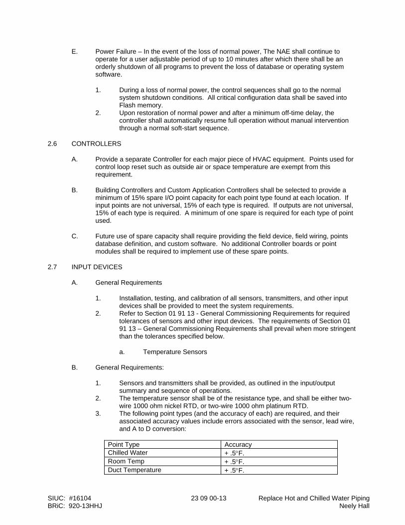
SIUC: #16104 23 09 00-13 Replace Hot and Chilled Water Piping BRiC: 920-13HHJ Neely Hall
E. Power Failure – In the event of the loss of normal power, The NAE shall continue to operate for a user adjustable period of up to 10 minutes after which there shall be an orderly shutdown of all programs to prevent the loss of database or operating system software.
1. During a loss of normal power, the control sequences shall go to the normal system shutdown conditions. All critical configuration data shall be saved into Flash memory.
2. Upon restoration of normal power and after a minimum off-time delay, the controller shall automatically resume full operation without manual intervention through a normal soft-start sequence.
2.6 CONTROLLERS
A. Provide a separate Controller for each major piece of HVAC equipment. Points used for control loop reset such as outside air or space temperature are exempt from this requirement.
B. Building Controllers and Custom Application Controllers shall be selected to provide a minimum of 15% spare I/O point capacity for each point type found at each location. If input points are not universal, 15% of each type is required. If outputs are not universal, 15% of each type is required. A minimum of one spare is required for each type of point used.
C. Future use of spare capacity shall require providing the field device, field wiring, points database definition, and custom software. No additional Controller boards or point modules shall be required to implement use of these spare points.
2.7 INPUT DEVICES
A. General Requirements
1. Installation, testing, and calibration of all sensors, transmitters, and other input devices shall be provided to meet the system requirements.
2. Refer to Section 01 91 13 - General Commissioning Requirements for required tolerances of sensors and other input devices. The requirements of Section 01 91 13 – General Commissioning Requirements shall prevail when more stringent than the tolerances specified below.
a. Temperature Sensors
B. General Requirements:
1. Sensors and transmitters shall be provided, as outlined in the input/output summary and sequence of operations.
2. The temperature sensor shall be of the resistance type, and shall be either two-wire 1000 ohm nickel RTD, or two-wire 1000 ohm platinum RTD.
3. The following point types (and the accuracy of each) are required, and their associated accuracy values include errors associated with the sensor, lead wire, and A to D conversion:
Point Type Accuracy Chilled Water + .5F. Room Temp + .5F. Duct Temperature + .5F.
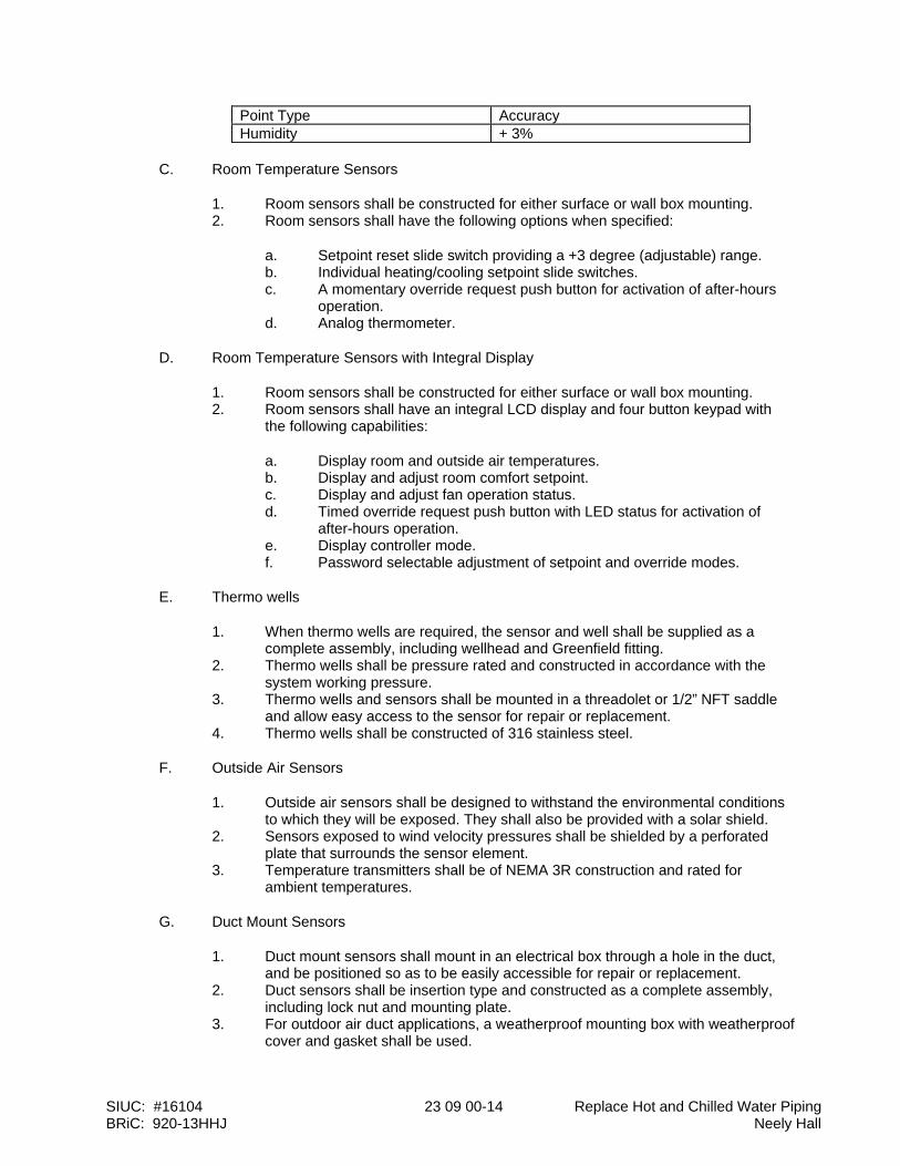
SIUC: #16104 23 09 00-14 Replace Hot and Chilled Water Piping BRiC: 920-13HHJ Neely Hall
Point Type Accuracy Humidity + 3%
C. Room Temperature Sensors
1. Room sensors shall be constructed for either surface or wall box mounting. 2. Room sensors shall have the following options when specified:
a. Setpoint reset slide switch providing a +3 degree (adjustable) range. b. Individual heating/cooling setpoint slide switches. c. A momentary override request push button for activation of after-hours
operation. d. Analog thermometer.
D. Room Temperature Sensors with Integral Display
1. Room sensors shall be constructed for either surface or wall box mounting. 2. Room sensors shall have an integral LCD display and four button keypad with
the following capabilities:
a. Display room and outside air temperatures. b. Display and adjust room comfort setpoint. c. Display and adjust fan operation status. d. Timed override request push button with LED status for activation of
after-hours operation. e. Display controller mode. f. Password selectable adjustment of setpoint and override modes.
E. Thermo wells
1. When thermo wells are required, the sensor and well shall be supplied as a complete assembly, including wellhead and Greenfield fitting.
2. Thermo wells shall be pressure rated and constructed in accordance with the system working pressure.
3. Thermo wells and sensors shall be mounted in a threadolet or 1/2” NFT saddle and allow easy access to the sensor for repair or replacement.
4. Thermo wells shall be constructed of 316 stainless steel.
F. Outside Air Sensors
1. Outside air sensors shall be designed to withstand the environmental conditions to which they will be exposed. They shall also be provided with a solar shield.
2. Sensors exposed to wind velocity pressures shall be shielded by a perforated plate that surrounds the sensor element.
3. Temperature transmitters shall be of NEMA 3R construction and rated for ambient temperatures.
G. Duct Mount Sensors
1. Duct mount sensors shall mount in an electrical box through a hole in the duct, and be positioned so as to be easily accessible for repair or replacement.
2. Duct sensors shall be insertion type and constructed as a complete assembly, including lock nut and mounting plate.
3. For outdoor air duct applications, a weatherproof mounting box with weatherproof cover and gasket shall be used.
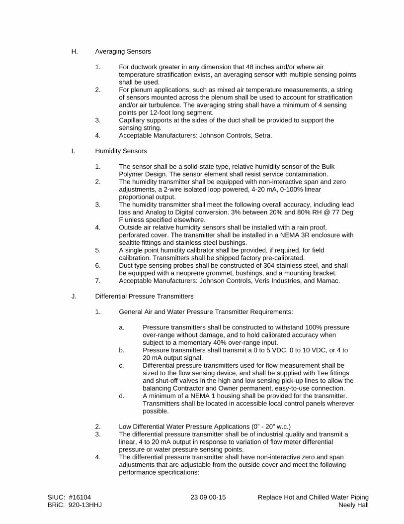
SIUC: #16104 23 09 00-15 Replace Hot and Chilled Water Piping BRiC: 920-13HHJ Neely Hall
H. Averaging Sensors
1. For ductwork greater in any dimension that 48 inches and/or where air temperature stratification exists, an averaging sensor with multiple sensing points shall be used.
2. For plenum applications, such as mixed air temperature measurements, a string of sensors mounted across the plenum shall be used to account for stratification and/or air turbulence. The averaging string shall have a minimum of 4 sensing points per 12-foot long segment.
3. Capillary supports at the sides of the duct shall be provided to support the sensing string.
4. Acceptable Manufacturers: Johnson Controls, Setra.
I. Humidity Sensors
1. The sensor shall be a solid-state type, relative humidity sensor of the Bulk Polymer Design. The sensor element shall resist service contamination.
2. The humidity transmitter shall be equipped with non-interactive span and zero adjustments, a 2-wire isolated loop powered, 4-20 mA, 0-100% linear proportional output.
3. The humidity transmitter shall meet the following overall accuracy, including lead loss and Analog to Digital conversion. 3% between 20% and 80% RH @ 77 Deg F unless specified elsewhere.
4. Outside air relative humidity sensors shall be installed with a rain proof, perforated cover. The transmitter shall be installed in a NEMA 3R enclosure with sealtite fittings and stainless steel bushings.
5. A single point humidity calibrator shall be provided, if required, for field calibration. Transmitters shall be shipped factory pre-calibrated.
6. Duct type sensing probes shall be constructed of 304 stainless steel, and shall be equipped with a neoprene grommet, bushings, and a mounting bracket.
7. Acceptable Manufacturers: Johnson Controls, Veris Industries, and Mamac.
J. Differential Pressure Transmitters
1. General Air and Water Pressure Transmitter Requirements:
a. Pressure transmitters shall be constructed to withstand 100% pressure over-range without damage, and to hold calibrated accuracy when subject to a momentary 40% over-range input.
b. Pressure transmitters shall transmit a 0 to 5 VDC, 0 to 10 VDC, or 4 to 20 mA output signal.
c. Differential pressure transmitters used for flow measurement shall be sized to the flow sensing device, and shall be supplied with Tee fittings and shut-off valves in the high and low sensing pick-up lines to allow the balancing Contractor and Owner permanent, easy-to-use connection.
d. A minimum of a NEMA 1 housing shall be provided for the transmitter. Transmitters shall be located in accessible local control panels wherever possible.
2. Low Differential Water Pressure Applications (0” - 20” w.c.) 3. The differential pressure transmitter shall be of industrial quality and transmit a
linear, 4 to 20 mA output in response to variation of flow meter differential pressure or water pressure sensing points.
4. The differential pressure transmitter shall have non-interactive zero and span adjustments that are adjustable from the outside cover and meet the following performance specifications:
SIUC: #16104 23 09 00-16 Replace Hot and Chilled Water Piping BRiC: 920-13HHJ Neely Hall
a. .01-20” w.c. input differential pressure range. b. 4-20 mA output. c. Maintain accuracy up to 20 to 1 ratio turndown. d. Reference Accuracy: +0.2% of full span.
5. Acceptable Manufacturers: Setra and Mamac.
K. Medium to High Differential Water Pressure Applications (Over 21” w.c.)
1. The differential pressure transmitter shall meet the low pressure transmitter specifications with the following exceptions:
a. Differential pressure range 10” w.c. to 300 PSI. b. Reference Accuracy: +1% of full span (includes non-linearity, hysteresis,
and repeatability).
2. Standalone pressure transmitters shall be mounted in a bypass valve assembly panel. The panel shall be constructed to NEMA 1 standards. The transmitter shall be installed in the panel with high and low connections piped and valved. Air bleed units, bypass valves, and compression fittings shall be provided.
3. Acceptable Manufacturers: Setra and Mamac.
L. Building Differential Air Pressure Applications (-1” to +1” w.c.)
1. The differential pressure transmitter shall be of industrial quality and transmit a linear, 4 to 20 mA output in response to variation of differential pressure or air pressure sensing points.
2. The differential pressure transmitter shall have non-interactive zero and span adjustments that are adjustable from the outside cover and meet the following performance specifications:
a. -1.00 to +1.00 w.c. input differential pressure ranges. (Select range appropriate for system application)
b. 4-20 mA output. c. Maintain accuracy up to 20 to 1 ratio turndown. d. Reference Accuracy: +0.2% of full span.
3. Acceptable Manufacturers: Johnson Controls and Setra.
M. Low Differential Air Pressure Applications (0” to 5” w.c.)
1. The differential pressure transmitter shall be of industrial quality and transmit a linear, 4 to 20 mA output in response to variation of differential pressure or air pressure sensing points.
2. The differential pressure transmitter shall have non-interactive zero and span adjustments that are adjustable from the outside cover and meet the following performance specifications:
a. (0.00 - 1.00” to 5.00”) w.c. input differential pressure ranges. (Select range appropriate for system application.)
b. 4-20 mA output. c. Maintain accuracy up to 20 to 1 ratio turndown. d. Reference Accuracy: +0.2% of full span.
3. Acceptable Manufacturers: Johnson Controls and Setra.
SIUC: #16104 23 09 00-17 Replace Hot and Chilled Water Piping BRiC: 920-13HHJ Neely Hall
N. Medium Differential Air Pressure Applications (5” to 21” w.c.)
1. The pressure transmitter shall be similar to the Low Air Pressure Transmitter, except that the performance specifications are not as severe. Differential pressure transmitters shall be provided that meet the following performance requirements:
a. Zero & span: (c/o F.S./Deg. F): .04% including linearity, hysteresis and repeatability.
b. Accuracy: 1% F.S. (best straight line) Static Pressure Effect: 0.5% F.S. (to 100 PSIG.
c. Thermal Effects: <+.033 F.S./Deg. F. over 40F. to 100F. (calibrated at 70F.).
2. Standalone pressure transmitters shall be mounted in a bypass valve assembly panel. The panel shall be constructed to NEMA 1 standards. The transmitter shall be installed in the panel with high and low connections piped and valved. Air bleed units, bypass valves, and compression fittings shall be provided.
3. Acceptable manufacturers: Johnson Controls and Setra.
O. Air Flow Monitoring
1. Fan Inlet Air Flow Measuring Stations
a. At the inlet of each fan and near the exit of the inlet sound trap, airflow traverse probes shall be provided that shall continuously monitor the fan air volumes and system velocity pressure.
b. Each traverse probe shall be of a dual manifolded, cylindrical, type 3003 extruded aluminum configuration, having an anodized finish to eliminate surface pitting and unnecessary air friction. The multiple total pressure manifold shall have sensors located along the stagnation plane of the approaching airflow. The manifold should not have forward projecting sensors into the air stream. The static pressure manifold shall incorporate dual offset static tops on the opposing sides of the averaging manifold so as to be insensitive to flow-angle variations of as much as + 20 in the approaching air stream.
c. The airflow traverse probe shall not induce a measurable pressure drop, nor shall the sound level within the duct be amplified by its singular or multiple presence in the air stream. Each airflow-measuring probe shall contain multiple total and static pressure sensors placed at equal distances along the probe length. The number of sensors on each probe and the quantity of probes utilized at each installation shall comply with the ASHRAE Standards for duct traversing.
d. Airflow measuring stations shall be manufactured by Air Monitor Corp., Tek-Air Systems, Inc., Ebtron, or Dietrich Standard.
2. Single Probe Air Flow Measuring Sensor
a. The single probe airflow-measuring sensor shall be duct mounted with an adjustable sensor insertion length of up to eight inches. The transmitter shall produce a 4-20 mA or 0-10 VDC signal linear to air velocity. The sensor shall be a hot wire anemometer and utilize two temperature sensors and a heater element temperature. The other sensor shall measure the downstream air temperature. The temperature differential shall be directly related to airflow velocity.
SIUC: #16104 23 09 00-18 Replace Hot and Chilled Water Piping BRiC: 920-13HHJ Neely Hall
3. Duct Air Flow Measuring Stations
a. Each device shall be designed and built to comply with, and provide results in accordance with, accepted practice as defined for system testing in the ASHRAE Handbook of fundamentals, as well as in the Industrial Ventilation Handbook.
b. Airflow measuring stations shall be fabricated of 14-gauge galvanized steel welded casing with 90 Deg. connecting flanges in configuration and size equal to that of the duct into which it is mounted. Each station shall be complete with an air directionalizer and parallel cell profile suppressor (3/4” maximum cell) across the entering air stream and mechanically fastened to the casing in such a way to withstand velocities up to 6000 feet per minute. This air directionalizer and parallel cell honeycomb suppressor shall provide 98% free area, equalize the velocity profile, and eliminate turbulent and rotational flow from the air stream prior to the measuring point.
c. The total pressure measurement side (high side) will be designed and spaced to the Industrial Ventilation Manual 16th Edition, Page 9-5. The self-averaging manifolding will be manufactured of brass and copper components.
d. The static pressure sensing probes (low side) shall be bullet-nosed shaped, per detailed radius, as illustrated in Industrial Ventilation Manual 16th Edition, Page 9-5.
e. The main take-off point from both the total pressure and the static pressure manifolds must be symmetrical.
f. Total and static pressure manifolds shall terminate with external ports for connection to control tubing. An identification label shall be placed on each unit casing, listing model number, size, area, and specified airflow capacity.
g. Acceptable manufacturers: Air Monitor Corp., Tek-Air, Ebtron, and Dietrich Standard.
h. Static Pressure Traverse Probe i. Duct static traverse probes shall be provided where required to monitor
duct static pressure. The probe shall contain multiple static pressure sensors located along exterior surface of the cylindrical probe.
j. Acceptable manufacturers: Cleveland Controls k. Shielded Static Air Probe l. A shielded static pressure probe shall be provided at each end of the
building. The probe shall have multiple sensing ports, an impulse suppression chamber, and airflow shielding. A suitable probe for indoor and outdoor locations shall be provided.
P. Water Flow Monitoring
1. Water flow meters shall be electromagnetic type with integral microprocessor-Based electronics. The meter shall have an accuracy of 0.25%.
2. Acceptable manufacturers: Onicon
Q. Power Monitoring Devices
1. Current Measurement (Amps)
a. Current measurement shall be by a combination current transformer and a current transducer. The current transformer shall be sized to reduce the full amperage of the monitored circuit to a maximum 5 Amp signal,

SIUC: #16104 23 09 00-19 Replace Hot and Chilled Water Piping BRiC: 920-13HHJ Neely Hall
which will be converted to a 4-20 mA DDC compatible signal for use by the Facility Management System.
b. Current Transformer – A split core current transformer shall be provided to monitor motor amps.
1) Operating frequency – 50 - 400 Hz. 2) Insulation – 0.6 Kv class 10Kv BIL. 3) UL recognized. 4) Five amp secondary. 5) Select current ration as appropriate for application. 6) Acceptable manufacturers: Veris Industries.
c. Current Transducer – A current to voltage or current to mA transducer shall be provided. The current transducer shall include:
1) 6X input over amp rating for AC inrushes of up to 120 amps. 2) Manufactured to UL 1244. 3) Accuracy: +.5%, Ripple +1%. 4) Minimum load resistance 30kOhm. 5) Input 0-20 Amps. 6) Output 4-20 mA. 7) Transducer shall be powered by a 24VDC regulated power
supply (24 VDC +5%). 8) Acceptable manufacturers: Veris Industries
R. Status and Safety Switches
1. General Requirements
a. Switches shall be provided to monitor equipment status, safety conditions, and generate alarms at the BAS when a failure or abnormal condition occurs. Safety switches shall be provided with two sets of contacts and shall be interlock wired to shut down respective equipment.
2. Current Sensing Switches
a. The current sensing switch shall be self-powered with solid-state circuitry and a dry contact output. It shall consist of a current transformer, a solid state current sensing circuit, adjustable trip point, solid state switch, SPDT relay, and an LED indicating the on or off status. A conductor of the load shall be passed through the window of the device. It shall accept over-current up to twice its trip point range.
b. Current sensing switches shall be used for run status for fans, pumps, and other miscellaneous motor loads.
c. Current sensing switches shall be calibrated to show a positive run status only when the motor is operating under load. A motor running with a broken belt or coupling shall indicate a negative run status.
d. Acceptable manufacturers: Veris Industries
S. Air Filter Status Switches
1. Differential pressure switches used to monitor air filter status shall be of the automatic reset type with SPDT contacts rated for 2 amps at 120VAC.
2. A complete installation kit shall be provided, including: static pressure tops, tubing, fittings, and air filters.
SIUC: #16104 23 09 00-20 Replace Hot and Chilled Water Piping BRiC: 920-13HHJ Neely Hall
3. Provide appropriate scale range and differential adjustment for intended service. 4. Acceptable manufacturers: Johnson Controls, Cleveland Controls
T. Air Flow Switches
1. Differential pressure flow switches shall be bellows actuated mercury switches or snap acting micro-switches with appropriate scale range and differential adjustment for intended service.
2. Acceptable manufacturers: Johnson Controls, Cleveland Controls
U. Air Pressure Safety Switches
1. Air pressure safety switches shall be of the manual reset type with SPDT contacts rated for 2 amps at 120VAC.
2. Pressure range shall be adjustable with appropriate scale range and differential adjustment for intended service.
3. Acceptable manufacturers: Johnson Controls, Cleveland Controls
V. Water Flow Switches
1. Water flow switches shall be equal to the Johnson Controls P74.
W. Low Temperature Limit Switches
1. The low temperature limit switch shall be of the manual reset type with Double Pole/Single Throw snap acting contacts rated for 16 amps at 120VAC.
2. The sensing element shall be a minimum of 15 feet in length and shall react to the coldest 18-inch section. Element shall be mounted horizontally across duct in accordance with manufacturers recommended installation procedures.
3. For large duct areas where the sensing element does not provide full coverage of the air stream, additional switches shall be provided as required to provide full protection of the air stream.
4. The low temperature limit switch shall be equal to Johnson Controls A70.
2.8 OUTPUT DEVICES
A. Actuators
1. General Requirements:
a. Damper and valve actuators shall be electronic and/or pneumatic, as specified in the System Description section.
B. Electronic Damper Actuators
1. Electronic damper actuators shall be direct shaft mount. 2. Modulating and two-position actuators shall be provided as required by the
sequence of operations. Damper sections shall be sized Based on actuator manufacturer’s recommendations for face velocity, differential pressure and damper type. The actuator mounting arrangement and spring return feature shall permit normally open or normally closed positions of the dampers, as required. All actuators (except terminal units) shall be furnished with mechanical spring return unless otherwise specified in the sequences of operations. All actuators shall have external adjustable stops to limit the travel in either direction, and a gear release to allow manual positioning.
SIUC: #16104 23 09 00-21 Replace Hot and Chilled Water Piping BRiC: 920-13HHJ Neely Hall
3. Modulating actuators shall accept 24 VAC or VDC power supply, consume no more than 15 VA, and be UL listed. The control signal shall be 2-10 VDC or 4-20 mA, and the actuator shall provide a clamp position feedback signal of 2-10 VDC. The feedback signal shall be independent of the input signal and may be used to parallel other actuators and provide true position indication. The feedback signal of one damper actuator for each separately controlled damper shall be wired back to a terminal strip in the control panel for trouble-shooting purposes.
4. Two-position or open/closed actuators shall accept 24 or 120 VAC power supply and be UL listed. Isolation, smoke, exhaust fan, and other dampers, as specified in the sequence of operations, shall be furnished with adjustable end switches to indicate open/closed position or be hard wired to start/stop associated fan. Two-position actuators, as specified in sequences of operations as “quick acting,” shall move full stroke within 20 seconds. All smoke damper actuators shall be quick acting.
5. Acceptable manufacturers: Johnson Controls, Mamac.
C. Electronic Valve Actuators
1. Electronic valve actuators shall be manufactured by the valve manufacturer. 2. Each actuator shall have current limiting circuitry incorporated in its design to
prevent damage to the actuator. 3. Modulating and two-position actuators shall be provided as required by the
sequence of operations. Actuators shall provide the minimum torque required for proper valve close-off against the system pressure for the required application. The valve actuator shall be sized Based on valve manufacturer’s recommendations for flow and pressure differential. All actuators shall fail in the last position unless specified with mechanical spring return in the sequence of operations. The spring return feature shall permit normally open or normally closed positions of the valves, as required. All direct shaft mount rotational actuators shall have external adjustable stops to limit the travel in either direction.
4. Modulating Actuators shall accept 24 VAC or VDC and 120 VAC power supply and be UL listed. The control signal shall be 2-10 VDC or 4-20 mA and the actuator shall provide a clamp position feedback signal of 2-10 VDC. The feedback signal shall be independent of the input signal, and may be used to parallel other actuators and provide true position indication. The feedback signal of each valve actuator (except terminal valves) shall be wired back to a terminal strip in the control panel for trouble-shooting purposes.
5. Two-position or open/closed actuators shall accept 24 or 120 VAC power supply and be UL listed. Butterfly isolation and other valves, as specified in the sequence of operations, shall be furnished with adjustable end switches to indicate open/closed position or be hard wired to start/stop the associated pump or chiller.
6. Acceptable manufacturers: Johnson Controls
D. Control Dampers
1. The BAS Contractor shall furnish all automatic dampers except those provided with air handling units. All automatic dampers shall be sized for the application by the BAS Contractor or as specifically indicated on the Drawings.
2. All dampers used for throttling airflow shall be of the opposed blade type arranged for normally open or normally closed operation, as required. The damper is to be sized so that, when wide open, the pressure drop is a sufficient amount of its close-off pressure drop to shift the characteristic curve to near linear.
3. All dampers used for two-position, open/close control shall be parallel blade type arranged for normally open or closed operation, as required.
SIUC: #16104 23 09 00-22 Replace Hot and Chilled Water Piping BRiC: 920-13HHJ Neely Hall
4. Damper frames and blades shall be constructed of either galvanized steel or aluminum. Maximum blade length in any section shall be 60”. Damper blades shall be 16-gauge minimum and shall not exceed eight (8) inches in width. Damper frames shall be 16-gauge minimum hat channel type with corner bracing. All damper bearings shall be made of reinforced nylon, stainless steel or oil-impregnated bronze. Dampers shall be tight closing, low leakage type, with synthetic elastomer seals on the blade edges and flexible stainless steel side seals. Dampers of 48”x48” size shall not leak in excess of 8.0 cfm per square foot when closed against 4” w.g. static pressure when tested in accordance with AMCA Std. 500.
5. Airfoil blade dampers of double skin construction with linkage out of the air stream shall be used whenever the damper face velocity exceeds 1500 FPM or system pressure exceeds 2.5” w.g., but no more than 4000 FPM or 6” w.g. Acceptable manufacturers are Johnson Controls D-7250 D-1250 or D-1300, Ruskin CD50, and Vent Products 5650.
6. One piece rolled blade dampers with exposed or concealed linkage may be used with face velocities of 1500 FPM or below. Acceptable manufacturers are: Johnson Controls D-1600, Ruskin CD36, and Vent Products 5800.
7. Multiple section dampers may be jack-shafted to allow mounting of piston pneumatic actuators and direct connect electronic actuators. Each end of the jackshaft shall receive at least one actuator to reduce jackshaft twist.
E. Control Relays
1. Control Pilot Relays
a. Control pilot relays shall be of a modular plug-in design with retaining springs or clips.
b. Mounting Bases shall be snap-mount. c. DPDT, 3PDT, or 4PDT relays shall be provided, as appropriate for
application. d. Contacts shall be rated for 10 amps at 120VAC. e. Relays shall have an integral indicator light and check button. f. Acceptable manufacturers: Johnson Controls, Lectro
F. Control Valves
1. All automatic control valves shall be fully proportioning and provide near linear heat transfer control. The valves shall be quiet in operation and fail-safe open, closed, or in their last position. All valves shall operate in sequence with another valve when required by the sequence of operations. All control valves shall be sized by the control manufacturer, and shall be guaranteed to meet the heating and cooling loads, as specified. All control valves shall be suitable for the system flow conditions and close against the differential pressures involved. Body pressure rating and connection type (sweat, screwed, or flanged) shall conform to the pipe schedule elsewhere in this Specification.
2. All chilled water control valves shall be pressure independent control valves. Modulating water valves shall be sized per manufacturer’s recommendations for the given application. In general, valves serving variable flow air handling unit coils shall be sized for a pressure drop equal to the actual coil pressure drop, but no less than 5 PSI.
3. Valves for terminal reheat coils shall be sized for a 2 PSIG pressure drop, but no more than a 5 PSI drop.
4. Ball valves shall be used for hot and chilled water applications, water terminal reheat coils, radiant panels, unit heaters, package air conditioning units, and fan coil units except those described hereinafter.
SIUC: #16104 23 09 00-23 Replace Hot and Chilled Water Piping BRiC: 920-13HHJ Neely Hall
5. Modulating plug water valves of the single-seat type with equal percentage flow characteristics shall be used for all special applications as indicated on the valve schedule. Valve discs shall be composition type. Valve stems shall be stainless steel.
6. Butterfly valves shall be acceptable for modulating large flow applications greater than modulating plug valves, and for all two-position, open/close applications. In-line and/or three-way butterfly valves shall be heavy-duty pattern with a body rating comparable to the pipe rating, replaceable lining suitable for temperature of system, and a stainless steel vane. Valves for modulating service shall be sized and travel limited to 50 degrees of full open. Valves for isolation service shall be the same as the pipe. Valves in the closed position shall be bubble-tight.
7. Acceptable manufacturers: Johnson Controls, Belimo Air Controls, Flow Control Industries.
G. Electronic Signal Isolation Transducers
1. A signal isolation transducer shall be provided whenever an analog output signal from the BAS is to be connected to an external control system as an input (such as a chiller control panel), or is to receive as an input signal from a remote system.
2. The signal isolation transducer shall provide ground plane isolation between systems.
3. Signals shall provide optical isolation between systems. 4. Acceptable manufacturers: Advanced Control Technologies
H. External Manual Override Stations
1. External manual override stations shall provide the following:
a. An integral HAND/OFF/AUTO switch shall override the controlled device pilot relay.
b. A status input to the Facility Management System shall indicate whenever the switch is not in the automatic position.
c. A Status LED shall illuminate whenever the output is ON. d. An Override LED shall illuminate whenever the HOA switch is in either
the HAND or OFF position. e. Contacts shall be rated for a minimum of 1 amp at 24 VAC.
2.9 MISCELLANEOUS DEVICES
A. Variable Frequency Motor Speed Control Drives – See Section 230514 – Variable Frequency Drives
B. Local Control Panels
1. All control panels shall be factory constructed, incorporating the BAS manufacturer’s standard designs and layouts. All control panels shall be UL inspected and listed as an assembly and carry a UL 508 label listing compliance. Control panels shall be fully enclosed, with perforated sub-panel, hinged door, and slotted flush latch.
2. In general, the control panels shall consist of the DDC controller(s), display module as specified and indicated on the plans, and I/O devices—such as relays, transducers, and so forth—that are not required to be located external to the control panel due to function. Where specified the display module shall be flush mounted in the panel face unless otherwise noted.

SIUC: #16104 23 09 00-24 Replace Hot and Chilled Water Piping BRiC: 920-13HHJ Neely Hall
3. All I/O connections on the DDC controller shall be provide via removable or fixed screw terminals.
4. Low and line voltage wiring shall be segregated. All provided terminal strips and wiring shall be UL listed, 300-volt service and provide adequate clearance for field wiring.
5. All wiring shall be neatly installed in plastic trays or tie-wrapped. 6. A convenience 120 VAC duplex receptacle shall be provided in each enclosure,
fused on/off power switch, and required transformers.
C. Power Supplies
1. DC power supplies shall be sized for the connected device load. Total rated load shall not exceed 75% of the rated capacity of the power supply.
a. Input: 120 VAC +10%, 60Hz. b. Output: 24 VDC. c. Line Regulation: +0.05% for 10% line change. d. Load Regulation: +0.05% for 50% load change. e. Ripple and Noise: 1 mV rms, 5 mV peak to peak.
2. An appropriately sized fuse and fuse block shall be provided and located next to the power supply.
a. A power disconnect switch shall be provided next to the power supply.
3. PERFORMANCE/EXECUTION
3.1 BAS SPECIFIC REQUIREMENTS
A. Graphic Displays
1. Provide a color graphic system flow diagram display for each system with all points as indicated on the point list. All terminal unit graphic displays shall be from a standard design library.
2. User shall access the various system schematics via a graphical penetration scheme and/or menu selection.
B. Custom Reports:
1. Provide custom reports as required for this project as directed by owner and defined in the points list.
C. Actuation Type
1. All Mechanical Equipment:
a. Actuation of Valves & Dampers to be Electric.
3.2 INSTALLATION PRACTICES
A. BAS Wiring
1. All conduit, wiring, accessories and wiring connections required for the installation of the Building Management System, as herein specified, shall be provided by the BAS Contractor unless specifically shown on the Electrical
SIUC: #16104 23 09 00-25 Replace Hot and Chilled Water Piping BRiC: 920-13HHJ Neely Hall
Drawings. All wiring shall comply with the requirements of applicable portions of 26 05 19 – Building Wire & Cable and all local and national electric codes, unless specified otherwise in this section.
2. All BAS wiring materials and installation methods shall comply with BAS manufacturer recommendations.
3. The sizing, type and provision of cable, conduit, cable trays, and raceways shall be the design responsibility of the BAS Contractor. If complications arise, however, due to the incorrect selection of cable, cable trays, raceways and/or conduit by the BAS Contractor, the Contractor shall be responsible for all costs incurred in replacing the selected components.
4. Class 2 Wiring
a. All Class 2 (24VAC or less) wiring shall be installed in conduit unless otherwise specified.
b. Conduit is not required for Class 2 wiring in concealed accessible locations. Class 2 wiring not installed in conduit shall be supported every 5’ from the building structure utilizing metal hangers designed for this application. Wiring shall be installed parallel to the building structural lines. All wiring shall be installed in accordance with local code requirements.
5. Class 2 signal wiring and 24VAC power can be run in the same conduit. Power wiring 120VAC and greater cannot share the same conduit with Class 2 signal wiring.
6. Provide for complete grounding of all applicable signal and communications cables, panels and equipment so as to ensure system integrity of operation. Ground cabling and conduit at the panel terminations. Avoid grounding loops.
B. BAS Line Voltage Power Source
1. 120-volt AC circuits used for the Building Management System shall be taken from panel boards and circuit breakers provided by 26 24 16 - Panelboards.
2. Circuits used for the BAS shall be dedicated to the BAS and shall not be used for any other purposes.
a. Basement: Panel GP-6: 13, 15, 17. b. Lower Level: Panel IP-6: 49, Panel IP-8: 44. c. First Floor: Panel 2P-8: 48. d. Second Floor: Panel 3p-8: 48.
3. DDC terminal unit controllers may use AC power from motor power circuits.
C. BAS Raceway
1. All wiring shall be installed in conduit or raceway except as noted elsewhere in this specification. Minimum control wiring conduit size 1/2”.
2. All conduits and raceways shall be installed level, plumb, at right angles to the building lines and shall follow the contours of the surface to which they are attached.
3. Flexible Metal Conduit shall be used for vibration isolation and shall be limited to 3 feet in length when terminating to vibrating equipment. Flexible Metal Conduit may be used within partition walls. Flexible Metal Conduit shall be UL listed.
4. BAS conduit shall be blue in color. See Specification Section 26 05 53 for identification for electrical systems.
SIUC: #16104 23 09 00-26 Replace Hot and Chilled Water Piping BRiC: 920-13HHJ Neely Hall
D. Penetrations
1. Provide fire stopping for all penetrations used by dedicated BAS conduits and raceways.
2. All openings in fire proofed or fire stopped components shall be closed by using approved fire resistive sealant.
3. All wiring passing through penetrations, including walls shall be in conduit or enclosed raceway.
4. Penetrations of floor slabs shall be by core drilling. All penetrations shall be plumb, true, and square.
E. BAS Identification Standards
1. Node Identification. All nodes shall be identified by a permanent label fastened to the enclosure. Labels shall be suitable for the node location.
2. Cable types specified in Item A shall be color coded for easy identification and troubleshooting.
F. BAS Panel Installation
1. The BAS contractor shall be responsible for coordinating panel locations with other trades and electrical and mechanical contractors.
G. Input Devices
1. All Input devices shall be installed per the manufacturer recommendation
Locate components of the BAS in accessible local control panels wherever possible.
H. HVAC Input Devices – Genera1
1. All Input devices shall be installed per the manufacturer recommendation 2. Locate components of the BAS in accessible local control panels wherever
possible. 3. The mechanical contractor shall install all in-line devices such as temperature
wells, pressure taps, airflow stations, etc. 4. Input Flow Measuring Devices shall be installed in strict compliance with ASME
guidelines affecting non-standard approach conditions. 5. Outside Air Sensors
a. Sensors shall be mounted on the North wall to minimize solar radiant heat impact or located in a continuous intake flow adequate to monitor outside air conditions accurately.
b. Sensors shall be installed with a rain proof, perforated cover.
6. Water Differential Pressure Sensors
a. Differential pressure transmitters used for flow measurement shall be sized to the flow-sensing device.
b. Differential pressure transmitters shall be supplied with tee fittings and shut-off valves in the high and low sensing pick-up lines.
c. The transmitters shall be installed in an accessible location wherever possible.
7. Medium to High Differential Water Pressure Applications (Over 21” w.c.):
SIUC: #16104 23 09 00-27 Replace Hot and Chilled Water Piping BRiC: 920-13HHJ Neely Hall
a. Air bleed units, bypass valves and compression fittings shall be provided.
8. Building/Space Differential Air Pressure Applications (-1” to +1” w.c.):
a. Transmitter’s exterior sensing tip shall be installed with a shielded static air probe to reduce pressure fluctuations caused by wind.
b. The interior tip shall be inconspicuous and located as shown on the drawings.
9. Air Flow Measuring Stations
a. Where the stations are installed in insulated ducts, the airflow passage of the station shall be the same size as the inside airflow dimension of the duct.
b. Station flanges shall be two inch to three inch to facilitate matching connecting ductwork.
10. Duct Temperature Sensors:
a. Duct mount sensors shall mount in an electrical box through a hole in the duct and be positioned so as to be easily accessible for repair or replacement.
b. The sensors shall be insertion type and constructed as a complete assembly including lock nut and mounting plate.
c. For ductwork greater in any dimension than 48 inches or where air temperature stratification exists such as a mixed air plenum, utilize an averaging sensor.
d. The sensor shall be mounted to suitable supports using factory approved element holders.
11. Space Sensors:
a. Shall be mounted per ADA requirements. b. Provide lockable tamper-proof covers in public areas and/or where
indicated on the plans.
12. Low Temperature Limit Switches:
a. Install on the discharge side of the first water or steam coil in the air stream.
b. Mount element horizontally across duct in a serpentine pattern insuring each square foot of coil is protected by 1 foot of sensor.
c. For large duct areas where the sensing element does not provide full coverage of the air stream, provide additional switches as required to provide full protection of the air stream.
I. Air Differential Pressure Status Switches:
1. Install with static pressure tips, tubing, fittings, and air filter.
J. Water Differential Pressure Status Switches:
1. Install with shut off valves for isolation.
K. HVAC Output Devices
SIUC: #16104 23 09 00-28 Replace Hot and Chilled Water Piping BRiC: 920-13HHJ Neely Hall
1. All output devices shall be installed per the manufacturer’s recommendation. The mechanical contractor shall install all in-line devices such as control valves, dampers, airflow stations, pressure wells, etc.
2. Actuators: All control actuators shall be sized capable of closing against the maximum system shut-off pressure. The actuator shall modulate in a smooth fashion through the entire stroke. When any pneumatic actuator is sequenced with another device, pilot positioners shall be installed to allow for proper sequencing.
3. Control Dampers: Shall be opposed blade for modulating control of airflow. Parallel blade dampers shall be installed for two position applications.
4. Control Valves: Shall be sized for proper flow control with equal percentage valve plugs. The maximum pressure drop for water applications shall be 5 PSI. The maximum pressure drop for steam applications shall be 7 PSI.
5. Electronic Signal Isolation Transducers: Whenever an analog output signal from the Building Management System is to be connected to an external control system as an input (such as a chiller control panel), or is to receive as an input a signal from a remote system, provide a signal isolation transducer. Signal isolation transducer shall provide ground plane isolation between systems. Signals shall provide optical isolation between systems.
3.3 TRAINING
A. The BAS contractor shall a minimum of four hours of on-site orientation by a system technician who is fully knowledgeable of the specific installation details of the project. This orientation shall, at a minimum, consist of a review of the project as-built drawings, the BAS software layout and naming conventions, and a walk through of the facility to identify panel and device locations.
3.4 SEQUENCE OF OPERATIONS
A. Hot/Chilled Water Pumps (HCWP-1, 2, 3 & 4):
1. The BAS enable/disable pump per campus schedule. 2. Pump will be set up as a constant flow pump, with the ability to be converted to a
variable flow pump in the future. For the present constant flow system, the variable frequency drive will be used to set design flow rate.
3. Summer Mode: When building is in the summer (cooling) mode and chilled water is available: a. The two-position valves located in the chilled water supply and chilled
water return piping shall be fully open. b. The two-position valves located in the hot water supply and hot water
return piping shall be fully closed. c. Three-Way Control Valve: The three-way control valve shall modulate
as required to maintain chilled water return temperature back the chilled water return main at a minimum of 52° F. (adjustable). Three-way control valve shall be fully open to the return, full closed to the bypass when chilled water return temperature is above 52° F. (adjustable). At no point shall the chilled water supply temperature be allowed to rise above 50° F. (adjustable).
4. Winter Mode: When building is in the winter (heating) mode and heating hot water is available: a. The two-position valves located in the chilled water supply and chilled
water return piping shall be fully closed.
SIUC: #16104 23 09 00-29 Replace Hot and Chilled Water Piping BRiC: 920-13HHJ Neely Hall
b. The two-position valves located in the hot water supply and hot water return piping shall be fully open.
B. Hot Water Pumps (HWP-1):
1. The BAS shall monitor outdoor air temperature and enable the hot water pump whenever outdoor air temperature drops below 60 F. (adjustable).
2. Pump will be set up as a constant flow pump, with the ability to be converted to a variable flow pump in the future. For the present constant flow system, the variable frequency drive will be used to set design flow rate.
3. The two-position valves located in the hot water supply and hot water return piping shall be fully open (valves shall be closed whenever pump is disabled).
C. Chilled Water Pump (CHWP-1):
1. The BAS shall monitor outdoor air temperature and enable the chilled water pump whenever outdoor air temperature rises above 65 F. (adjustable).
2. The BAS shall monitor system differential pressure and vary pump speed as required to maintain the specified system pressure.
3. The two-position valves located in the chilled water supply and chilled water return piping shall be fully open (valves shall be closed whenever pump is disabled).
4. The bypass valve shall modulate open as required to maintain the maximum system differential pressure set point (adjustable). The bypass valve shall be sized for maximum flow of 15% of the hot water pump flow rate (62 gpm). Provide temperature sensor in the bypass piping downstream of the bypass valve to monitor water temperature in the bypass piping for verification that bypass valve is fully closed unless commanded open.
3.5 POINTS LIST- APPENDIX A
END OF SECTION
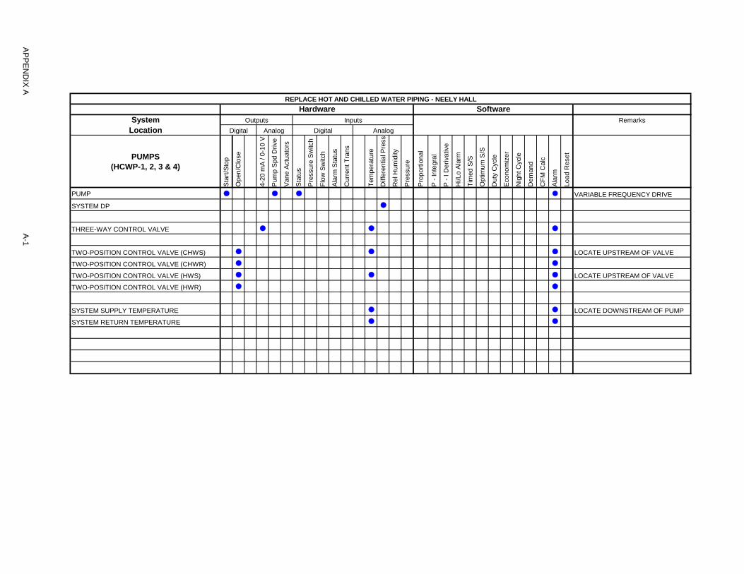
REPLACE HOT AND CHILLED WATER PIPING - NEELY HALL
Hardware SoftwareSystem Outputs Inputs Remarks
Location Digital Analog Digital Analog
PUMPS(HCWP-1, 2, 3 & 4)
Sta
rt/S
top
Op
en
/Clo
se
4-2
0 m
A /
0-1
0 V
Pu
mp
Sp
d D
rive
Va
ne
Act
ua
tors
Sta
tus
Pre
ssu
re S
witc
h
Flo
w S
witc
h
Ala
rm S
tatu
s
Cu
rre
nt T
ran
s
Tem
pe
ratu
re
Diff
ere
ntia
l Pre
ss
Re
l Hu
mid
ity
Pre
ssu
re
Pro
po
rtio
na
l
P -
Inte
gra
l
P -
I D
eri
vativ
e
Hi/L
o A
larm
Tim
ed
S/S
Op
timu
m S
/S
Du
ty C
ycle
Eco
no
miz
er
Nig
ht C
ycle
De
man
d
CF
M C
alc
Ala
rm
Lo
ad
Re
set
PUMP l l l l VARIABLE FREQUENCY DRIVE
SYSTEM DP l
THREE-WAY CONTROL VALVE l l l
TWO-POSITION CONTROL VALVE (CHWS) l l l LOCATE UPSTREAM OF VALVE
TWO-POSITION CONTROL VALVE (CHWR) l l
TWO-POSITION CONTROL VALVE (HWS) l l l LOCATE UPSTREAM OF VALVE
TWO-POSITION CONTROL VALVE (HWR) l l
SYSTEM SUPPLY TEMPERATURE l l LOCATE DOWNSTREAM OF PUMP
SYSTEM RETURN TEMPERATURE l l
AP
PE
ND
IX A
A-1
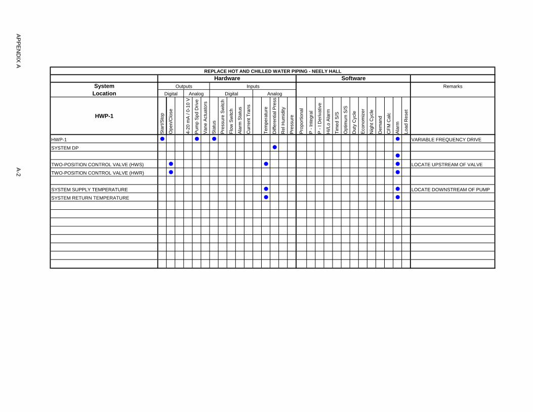
REPLACE HOT AND CHILLED WATER PIPING - NEELY HALL
Hardware SoftwareSystem Outputs Inputs Remarks
Location Digital Analog Digital Analog
HWP-1
Sta
rt/S
top
Op
en
/Clo
se
4-2
0 m
A /
0-1
0 V
Pu
mp
Sp
d D
rive
Va
ne
Act
ua
tors
Sta
tus
Pre
ssu
re S
witc
h
Flo
w S
witc
h
Ala
rm S
tatu
s
Cu
rre
nt T
ran
s
Tem
pe
ratu
re
Diff
ere
ntia
l Pre
ss
Re
l Hu
mid
ity
Pre
ssu
re
Pro
po
rtio
na
l
P -
Inte
gra
l
P -
I D
eri
vativ
e
Hi/L
o A
larm
Tim
ed
S/S
Op
timu
m S
/S
Du
ty C
ycle
Eco
no
miz
er
Nig
ht C
ycle
De
man
d
CF
M C
alc
Ala
rm
Lo
ad
Re
set
HWP-1 l l l l VARIABLE FREQUENCY DRIVE
SYSTEM DP l
l
TWO-POSITION CONTROL VALVE (HWS) l l l LOCATE UPSTREAM OF VALVE
TWO-POSITION CONTROL VALVE (HWR) l l
SYSTEM SUPPLY TEMPERATURE l l LOCATE DOWNSTREAM OF PUMP
SYSTEM RETURN TEMPERATURE l l
AP
PE
ND
IX A
A-2

REPLACE HOT AND CHILLED WATER PIPING - NEELY HALL
Hardware SoftwareSystem Outputs Inputs Remarks
Location Digital Analog Digital Analog
CHWP-1
Sta
rt/S
top
Op
en
/Clo
se
4-2
0 m
A /
0-1
0 V
Pu
mp
Sp
d D
rive
Va
ne
Act
ua
tors
Sta
tus
Pre
ssu
re S
witc
h
Flo
w S
witc
h
Ala
rm S
tatu
s
Cu
rre
nt T
ran
s
Tem
pe
ratu
re
Diff
ere
ntia
l Pre
ss
Re
l Hu
mid
ity
Pre
ssu
re
Pro
po
rtio
na
l
P -
Inte
gra
l
P -
I D
eri
vativ
e
Hi/L
o A
larm
Tim
ed
S/S
Op
timu
m S
/S
Du
ty C
ycle
Eco
no
miz
er
Nig
ht C
ycle
De
man
d
CF
M C
alc
Ala
rm
Lo
ad
Re
set
CHWP-1 l l l l VARIABLE FREQUENCY DRIVE
SYSTEM DP l
CHW BYPASS VALVE l l l
TWO-POSITION CONTROL VALVE (CHWS) l l l LOCATE UPSTREAM OF VALVE
TWO-POSITION CONTROL VALVE (CHWR) l l
SYSTEM SUPPLY TEMPERATURE l l LOCATE DOWNSTREAM OF PUMP
SYSTEM RETURN TEMPERATURE l l
AP
PE
ND
IX A
A-3
SIUC: #16104 23 21 13-1 Replace Hot and Chilled Water Piping BRiC: 920-13HHJ Neely Hall
DIVISION 23 - HEATING VENTILATING AND AIR CONDITIONING Section 23 21 13 – Hydronic Piping
1. GENERAL
1.1 WORK INCLUDES:
A. Base Bid:
1. Heating Contractor shall provide pipe and fitting materials, joining methods, special-duty valves, and specialties for the following:
a. Hot-water heating piping. b. Chilled-water piping.
B. Alternate Bid No. 1:
1. Heating Contractor shall provide pipe and fitting materials, joining methods, special-duty valves, and specialties for the chilled water piping associated with the installation of CHWP-1.
1.2 RELATED WORK
A. Specified elsewhere:
1. Section 23 21 23 - Hydronic Pumps for pumps, motors, and accessories for hydronic piping.
1.3 DEFINITIONS
A. PTFE: Polytetrafluoroethylene.
B. RTRF: Reinforced thermosetting resin (fiberglass) fittings.
C. RTRP: Reinforced thermosetting resin (fiberglass) pipe.
1.4 PERFORMANCE REQUIREMENTS
A. Hydronic piping components and installation shall be capable of withstanding the following minimum working pressure and temperature:
1. Working pressure is equal to the relief pressure plus the static height of the system and pumping head. The only working pressure mandated by authorities having jurisdiction is for makeup water.
2. Hot-Water Heating Piping: 200 deg F. 3. Chilled-Water Piping: 200 deg F.
1.5 SUBMITTALS
A. Product Data: For each type of the following:
1. Valves. Include flow and pressure drop curves based on manufacturer's testing for calibrated-orifice balancing valves and automatic flow-control valves.
2. Air control devices. 3. Chemical treatment. 4. Hydronic specialties.
B. Welding certificates.
SIUC: #16104 23 21 13-2 Replace Hot and Chilled Water Piping BRiC: 920-13HHJ Neely Hall
C. Field quality-control test reports.
D. Operation and Maintenance Data: For air control devices, hydronic specialties, and special-duty valves to include in emergency, operation, and maintenance manuals.
E. Water Analysis: Submit a copy of the water analysis to illustrate water quality available at Project site.
1.6 QUALITY ASSURANCE
A. Steel Support Welding: Qualify processes and operators according to AWS D1.1/D1.1M, "Structural Welding Code - Steel."
B. Welding: Qualify processes and operators according to ASME Boiler and Pressure Vessel Code: Section IX.
1. Comply with provisions in ASME B31 Series, "Code for Pressure Piping." 2. Certify that each welder has passed AWS qualification tests for welding
processes involved and that certification is current.
C. ASME Compliance: Comply with ASME B31.9, "Building Services Piping," for materials, products, and installation. Safety valves and pressure vessels shall bear the appropriate ASME label. Fabricate and stamp air separators and expansion tanks to comply with ASME Boiler and Pressure Vessel Code: Section VIII, Division 01.
2. PRODUCTS
2.1 COPPER TUBE AND FITTINGS
A. Drawn-Temper Copper Tubing: ASTM B 88, Type L.
B. Annealed-Temper Copper Tubing: ASTM B 88, Type K.
C. DWV Copper Tubing: ASTM B 306, Type DWV.
D. Wrought-Copper Fittings: ASME B16.22.
2.2 STEEL PIPE AND FITTINGS
A. Steel Pipe: ASTM A 53/A 53M, black steel with plain ends; type, grade, and wall thickness as indicated in Part 3 "Piping Applications" Article.
B. Cast-Iron Threaded Fittings: ASME B16.4; Classes 125 and 250 as indicated in Part 3 "Piping Applications" Article.
C. Malleable-Iron Threaded Fittings: ASME B16.3, Classes 150 and 300 as indicated in Part 3 "Piping Applications" Article.
D. Malleable-Iron Unions: ASME B16.39; Classes 150, 250, and 300 as indicated in Part 3 "Piping Applications" Article.
E. Cast-Iron Pipe Flanges and Flanged Fittings: ASME B16.1, Classes 25, 125, and 250; raised ground face, and bolt holes spot faced as indicated in Part 3 "Piping Applications" Article.
F. Wrought-Steel Fittings: ASTM A 234/A 234M, wall thickness to match adjoining pipe.
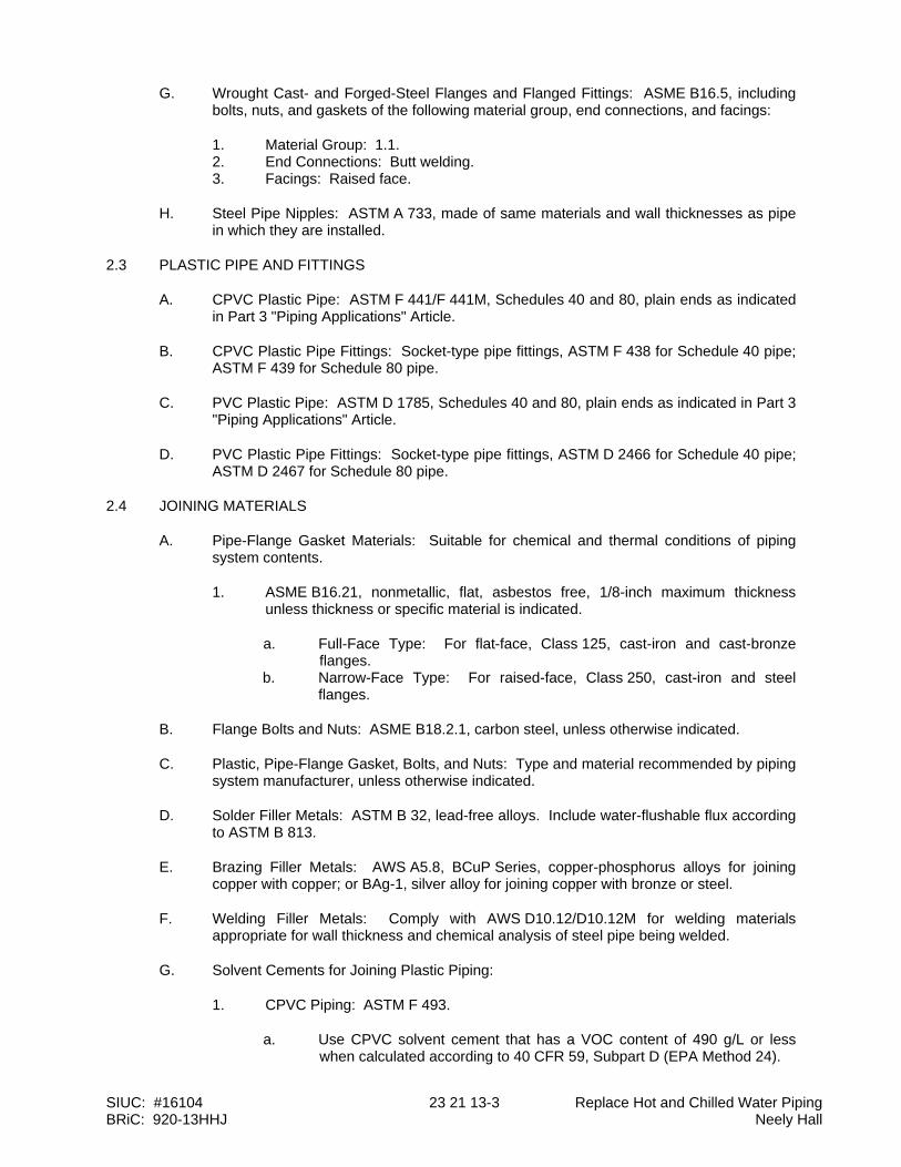
SIUC: #16104 23 21 13-3 Replace Hot and Chilled Water Piping BRiC: 920-13HHJ Neely Hall
G. Wrought Cast- and Forged-Steel Flanges and Flanged Fittings: ASME B16.5, including bolts, nuts, and gaskets of the following material group, end connections, and facings:
1. Material Group: 1.1. 2. End Connections: Butt welding. 3. Facings: Raised face.
H. Steel Pipe Nipples: ASTM A 733, made of same materials and wall thicknesses as pipe in which they are installed.
2.3 PLASTIC PIPE AND FITTINGS
A. CPVC Plastic Pipe: ASTM F 441/F 441M, Schedules 40 and 80, plain ends as indicated in Part 3 "Piping Applications" Article.
B. CPVC Plastic Pipe Fittings: Socket-type pipe fittings, ASTM F 438 for Schedule 40 pipe; ASTM F 439 for Schedule 80 pipe.
C. PVC Plastic Pipe: ASTM D 1785, Schedules 40 and 80, plain ends as indicated in Part 3 "Piping Applications" Article.
D. PVC Plastic Pipe Fittings: Socket-type pipe fittings, ASTM D 2466 for Schedule 40 pipe; ASTM D 2467 for Schedule 80 pipe.
2.4 JOINING MATERIALS
A. Pipe-Flange Gasket Materials: Suitable for chemical and thermal conditions of piping system contents.
1. ASME B16.21, nonmetallic, flat, asbestos free, 1/8-inch maximum thickness unless thickness or specific material is indicated.
a. Full-Face Type: For flat-face, Class 125, cast-iron and cast-bronze flanges.
b. Narrow-Face Type: For raised-face, Class 250, cast-iron and steel flanges.
B. Flange Bolts and Nuts: ASME B18.2.1, carbon steel, unless otherwise indicated.
C. Plastic, Pipe-Flange Gasket, Bolts, and Nuts: Type and material recommended by piping system manufacturer, unless otherwise indicated.
D. Solder Filler Metals: ASTM B 32, lead-free alloys. Include water-flushable flux according to ASTM B 813.
E. Brazing Filler Metals: AWS A5.8, BCuP Series, copper-phosphorus alloys for joining copper with copper; or BAg-1, silver alloy for joining copper with bronze or steel.
F. Welding Filler Metals: Comply with AWS D10.12/D10.12M for welding materials appropriate for wall thickness and chemical analysis of steel pipe being welded.
G. Solvent Cements for Joining Plastic Piping:
1. CPVC Piping: ASTM F 493.
a. Use CPVC solvent cement that has a VOC content of 490 g/L or less when calculated according to 40 CFR 59, Subpart D (EPA Method 24).
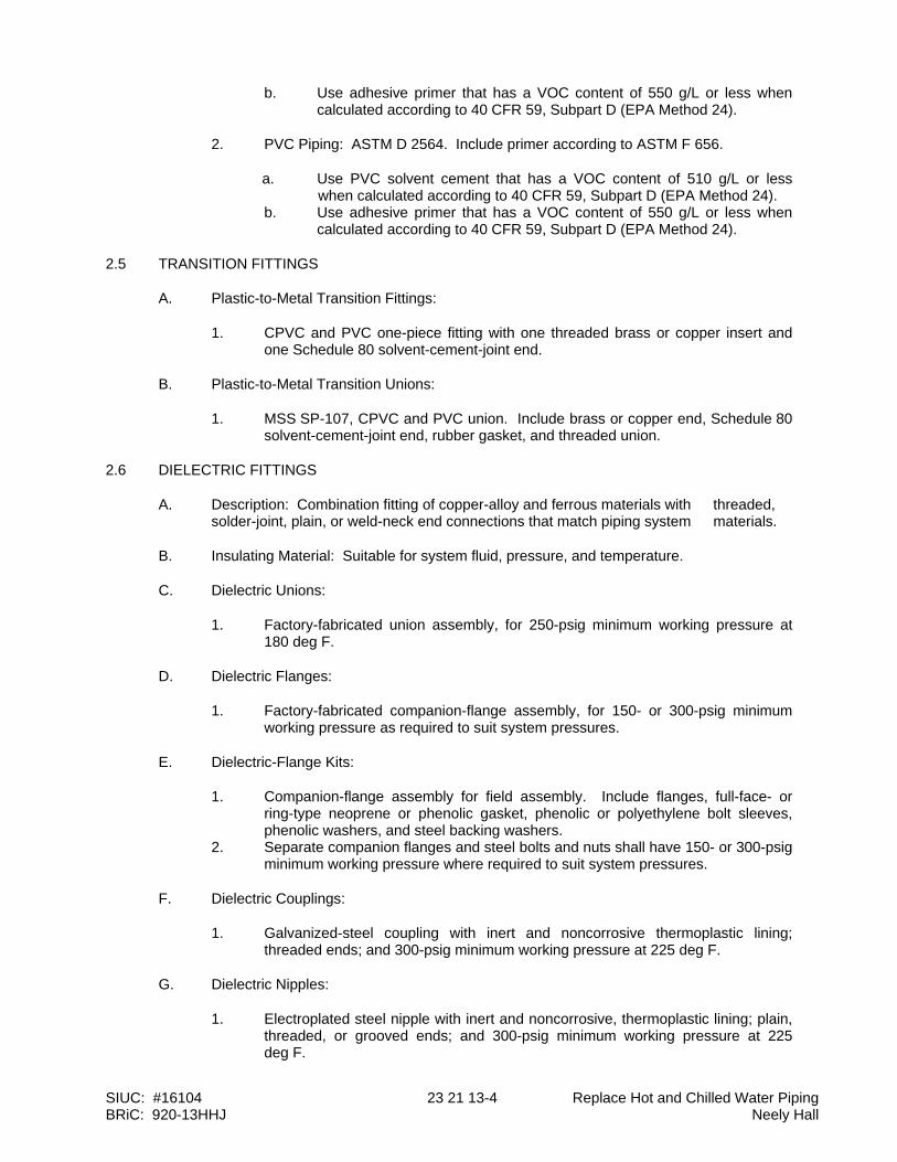
SIUC: #16104 23 21 13-4 Replace Hot and Chilled Water Piping BRiC: 920-13HHJ Neely Hall
b. Use adhesive primer that has a VOC content of 550 g/L or less when calculated according to 40 CFR 59, Subpart D (EPA Method 24).
2. PVC Piping: ASTM D 2564. Include primer according to ASTM F 656.
a. Use PVC solvent cement that has a VOC content of 510 g/L or less when calculated according to 40 CFR 59, Subpart D (EPA Method 24).
b. Use adhesive primer that has a VOC content of 550 g/L or less when calculated according to 40 CFR 59, Subpart D (EPA Method 24).
2.5 TRANSITION FITTINGS
A. Plastic-to-Metal Transition Fittings:
1. CPVC and PVC one-piece fitting with one threaded brass or copper insert and one Schedule 80 solvent-cement-joint end.
B. Plastic-to-Metal Transition Unions:
1. MSS SP-107, CPVC and PVC union. Include brass or copper end, Schedule 80 solvent-cement-joint end, rubber gasket, and threaded union.
2.6 DIELECTRIC FITTINGS
A. Description: Combination fitting of copper-alloy and ferrous materials with threaded, solder-joint, plain, or weld-neck end connections that match piping system materials.
B. Insulating Material: Suitable for system fluid, pressure, and temperature.
C. Dielectric Unions:
1. Factory-fabricated union assembly, for 250-psig minimum working pressure at 180 deg F.
D. Dielectric Flanges:
1. Factory-fabricated companion-flange assembly, for 150- or 300-psig minimum working pressure as required to suit system pressures.
E. Dielectric-Flange Kits:
1. Companion-flange assembly for field assembly. Include flanges, full-face- or ring-type neoprene or phenolic gasket, phenolic or polyethylene bolt sleeves, phenolic washers, and steel backing washers.
2. Separate companion flanges and steel bolts and nuts shall have 150- or 300-psig minimum working pressure where required to suit system pressures.
F. Dielectric Couplings:
1. Galvanized-steel coupling with inert and noncorrosive thermoplastic lining; threaded ends; and 300-psig minimum working pressure at 225 deg F.
G. Dielectric Nipples:
1. Electroplated steel nipple with inert and noncorrosive, thermoplastic lining; plain, threaded, or grooved ends; and 300-psig minimum working pressure at 225 deg F.

SIUC: #16104 23 21 13-5 Replace Hot and Chilled Water Piping BRiC: 920-13HHJ Neely Hall
2.7 VALVES
A. Globe, Check and Ball Valves: Comply with requirements specified in Section 23 05 23 - General-Duty Valves for HVAC Piping.
B. Automatic Temperature-Control Valves, Actuators, and Sensors: Comply with requirements specified in Section 23 09 00 – HVAC Instrumentation and Controls.
C. Bronze, Calibrated-Orifice, Balancing Valves:
1. Manufacturers: Subject to compliance with requirements, provide products by one of the following:
a. Armstrong Pumps, Inc. b. Bell & Gossett Domestic Pump; a division of ITT Industries. c. Griswold Controls. d. Taco.
2. Body: Bronze, ball or plug type with calibrated orifice or venturi. 3. Ball: Brass or stainless steel. 4. Plug: Resin. 5. Seat: PTFE. 6. End Connections: Threaded or socket. 7. Pressure Gage Connections: Integral seals for portable differential pressure
meter. 8. Handle Style: Lever, with memory stop to retain set position. 9. CWP Rating: Minimum 125 psig. 10. Maximum Operating Temperature: 250 deg F.
D. Cast-Iron or Steel, Calibrated-Orifice, Balancing Valves:
1. Manufacturers: Subject to compliance with requirements, provide products by one of the following:
a. Armstrong Pumps, Inc. b. Bell & Gossett Domestic Pump; a division of ITT Industries. c. Griswold Controls. d. Taco. e. Tour & Andersson; available through Victaulic Company of America.
2. Body: Cast-iron or steel body, ball, plug, or globe pattern with calibrated orifice or venturi.
3. Ball: Brass or stainless steel. 4. Stem Seals: EPDM O-rings. 5. Disc: Glass and carbon-filled PTFE. 6. Seat: PTFE. 7. End Connections: Flanged or grooved. 8. Pressure Gage Connections: Integral seals for portable differential pressure
meter. 9. Handle Style: Lever, with memory stop to retain set position. 10. CWP Rating: Minimum 125 psig. 11. Maximum Operating Temperature: 250 deg F.
E. Automatic Flow-Control Valves:
1. Manufacturers: Subject to compliance with requirements, provide products by one of the following:
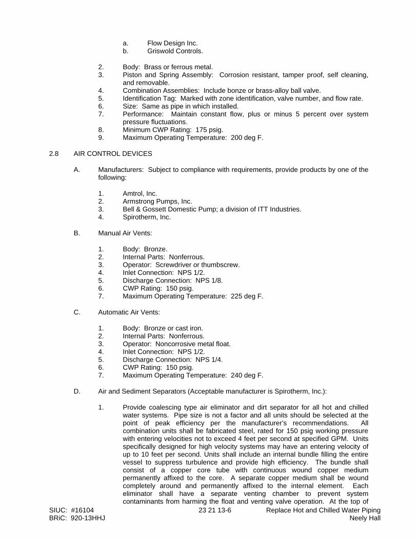
SIUC: #16104 23 21 13-6 Replace Hot and Chilled Water Piping BRiC: 920-13HHJ Neely Hall
a. Flow Design Inc. b. Griswold Controls.
2. Body: Brass or ferrous metal. 3. Piston and Spring Assembly: Corrosion resistant, tamper proof, self cleaning,
and removable. 4. Combination Assemblies: Include bonze or brass-alloy ball valve. 5. Identification Tag: Marked with zone identification, valve number, and flow rate. 6. Size: Same as pipe in which installed. 7. Performance: Maintain constant flow, plus or minus 5 percent over system
pressure fluctuations. 8. Minimum CWP Rating: 175 psig. 9. Maximum Operating Temperature: 200 deg F.
2.8 AIR CONTROL DEVICES
A. Manufacturers: Subject to compliance with requirements, provide products by one of the following:
1. Amtrol, Inc. 2. Armstrong Pumps, Inc. 3. Bell & Gossett Domestic Pump; a division of ITT Industries. 4. Spirotherm, Inc.
B. Manual Air Vents:
1. Body: Bronze. 2. Internal Parts: Nonferrous. 3. Operator: Screwdriver or thumbscrew. 4. Inlet Connection: NPS 1/2. 5. Discharge Connection: NPS 1/8. 6. CWP Rating: 150 psig. 7. Maximum Operating Temperature: 225 deg F.
C. Automatic Air Vents:
1. Body: Bronze or cast iron. 2. Internal Parts: Nonferrous. 3. Operator: Noncorrosive metal float. 4. Inlet Connection: NPS 1/2. 5. Discharge Connection: NPS 1/4. 6. CWP Rating: 150 psig. 7. Maximum Operating Temperature: 240 deg F.
D. Air and Sediment Separators (Acceptable manufacturer is Spirotherm, Inc.):
1. Provide coalescing type air eliminator and dirt separator for all hot and chilled water systems. Pipe size is not a factor and all units should be selected at the point of peak efficiency per the manufacturer’s recommendations. All combination units shall be fabricated steel, rated for 150 psig working pressure with entering velocities not to exceed 4 feet per second at specified GPM. Units specifically designed for high velocity systems may have an entering velocity of up to 10 feet per second. Units shall include an internal bundle filling the entire vessel to suppress turbulence and provide high efficiency. The bundle shall consist of a copper core tube with continuous wound copper medium permanently affixed to the core. A separate copper medium shall be wound completely around and permanently affixed to the internal element. Each eliminator shall have a separate venting chamber to prevent system contaminants from harming the float and venting valve operation. At the top of

SIUC: #16104 23 21 13-7 Replace Hot and Chilled Water Piping BRiC: 920-13HHJ Neely Hall
the venting chamber shall be an integral full port float actuated brass venting mechanism. Units shall include a valved side tap to flush floating dirt or liquids and for quick bleeding of large amounts of air during system fill or refill. Separator shall have the vessel extended below the pipe connections an equal distance for dirt separation. Air Eliminators shall be capable of removing 100% of the free air, 100% of the entrained air, and up to 99.6% of the dissolved air in the system fluid. Dirt separation shall be at least 80% of all particles 30 micron and larger within 100 passes. Separator shall include a removable lower head to facilitate removal of the internal bundle assembly for inspection or cleaning.
E. Air Purgers:
1. Body: Cast iron with internal baffles that slow the water velocity to separate the air from solution and divert it to the vent for quick removal.
2. Maximum Working Pressure: 150 psig. 3. Maximum Operating Temperature: 250 deg F.
2.9 CHEMICAL TREATMENT
A. Bypass Chemical Feeder: Welded steel construction; 125-psig working pressure; 5-gal. capacity; with fill funnel and inlet, outlet, and drain valves.
1. Chemicals: Specially formulated, based on analysis of makeup water, to prevent accumulation of scale and corrosion in piping and connected equipment.
2.10 HYDRONIC PIPING SPECIALTIES
A. Y-Pattern Strainers:
1. Body: ASTM A 126, Class B, cast iron with bolted cover and bottom drain connection.
2. End Connections: Threaded ends for NPS 2 and smaller; flanged ends for NPS 2-1/2 and larger.
3. Strainer Screen: 60-mesh startup strainer, and perforated stainless-steel basket with 50 percent free area.
4. CWP Rating: 125 psig.
B. Basket Strainers:
1. Body: ASTM A 126, Class B, high-tensile cast iron with bolted cover and bottom drain connection.
2. End Connections: Threaded ends for NPS 2 and smaller; flanged ends for NPS 2-1/2 and larger.
3. Strainer Screen: 40-mesh startup strainer, and perforated stainless-steel basket with 50 percent free area.
4. CWP Rating: 125 psig.
C. Stainless-Steel Bellow, Flexible Connectors:
1. Body: Stainless-steel bellows with woven, flexible, bronze, wire-reinforcing protective jacket.
2. End Connections: Threaded or flanged to match equipment connected. 3. Performance: Capable of 3/4-inch misalignment. 4. CWP Rating: 150 psig. 5. Maximum Operating Temperature: 250 deg F.
D. Spherical, Rubber, Flexible Connectors:
1. Body: Fiber-reinforced rubber body.
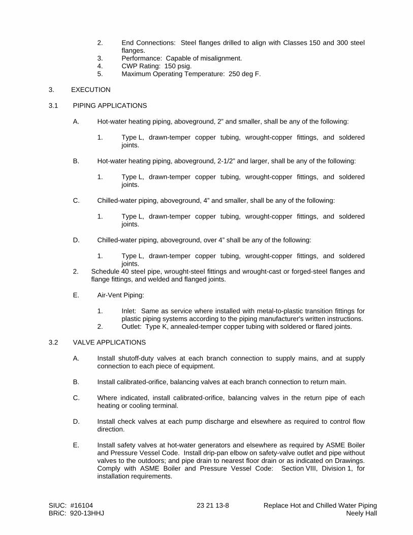
SIUC: #16104 23 21 13-8 Replace Hot and Chilled Water Piping BRiC: 920-13HHJ Neely Hall
2. End Connections: Steel flanges drilled to align with Classes 150 and 300 steel flanges.
3. Performance: Capable of misalignment. 4. CWP Rating: 150 psig. 5. Maximum Operating Temperature: 250 deg F.
3. EXECUTION
3.1 PIPING APPLICATIONS
A. Hot-water heating piping, aboveground, 2” and smaller, shall be any of the following:
1. Type L, drawn-temper copper tubing, wrought-copper fittings, and soldered joints.
B. Hot-water heating piping, aboveground, 2-1/2” and larger, shall be any of the following:
1. Type L, drawn-temper copper tubing, wrought-copper fittings, and soldered joints.
C. Chilled-water piping, aboveground, 4” and smaller, shall be any of the following:
1. Type L, drawn-temper copper tubing, wrought-copper fittings, and soldered joints.
D. Chilled-water piping, aboveground, over 4” shall be any of the following:
1. Type L, drawn-temper copper tubing, wrought-copper fittings, and soldered joints.
2. Schedule 40 steel pipe, wrought-steel fittings and wrought-cast or forged-steel flanges and flange fittings, and welded and flanged joints.
E. Air-Vent Piping:
1. Inlet: Same as service where installed with metal-to-plastic transition fittings for plastic piping systems according to the piping manufacturer's written instructions.
2. Outlet: Type K, annealed-temper copper tubing with soldered or flared joints.
3.2 VALVE APPLICATIONS
A. Install shutoff-duty valves at each branch connection to supply mains, and at supply connection to each piece of equipment.
B. Install calibrated-orifice, balancing valves at each branch connection to return main.
C. Where indicated, install calibrated-orifice, balancing valves in the return pipe of each heating or cooling terminal.
D. Install check valves at each pump discharge and elsewhere as required to control flow direction.
E. Install safety valves at hot-water generators and elsewhere as required by ASME Boiler and Pressure Vessel Code. Install drip-pan elbow on safety-valve outlet and pipe without valves to the outdoors; and pipe drain to nearest floor drain or as indicated on Drawings. Comply with ASME Boiler and Pressure Vessel Code: Section VIII, Division 1, for installation requirements.
SIUC: #16104 23 21 13-9 Replace Hot and Chilled Water Piping BRiC: 920-13HHJ Neely Hall
3.3 PIPING INSTALLATIONS
A. Drawing plans, schematics, and diagrams indicate general location and arrangement of piping systems. Indicate piping locations and arrangements if such were used to size pipe and calculate friction loss, expansion, pump sizing, and other design considerations. Install piping as indicated unless deviations to layout are approved on Coordination Drawings.
B. Install piping in concealed locations, unless otherwise indicated and except in equipment rooms and service areas.
C. Install piping indicated to be exposed and piping in equipment rooms and service areas at right angles or parallel to building walls. Diagonal runs are prohibited unless specifically indicated otherwise.
D. Install piping above accessible ceilings to allow sufficient space for ceiling panel removal.
E. Install piping to permit valve servicing.
F. Install piping at indicated slopes.
G. Install piping free of sags and bends.
H. Install fittings for changes in direction and branch connections.
I. Install piping to allow application of insulation.
J. Select system components with pressure rating equal to or greater than system operating pressure.
K. Install groups of pipes parallel to each other, spaced to permit applying insulation and servicing of valves.
L. Install drains, consisting of a tee fitting, NPS 3/4 ball valve, and short NPS 3/4 threaded nipple with cap, at low points in piping system mains and elsewhere as required for system drainage.
M. Install piping at a uniform grade of 0.2 percent upward in direction of flow.
N. Install condensate drain piping at a minimum slope of 1 percent downward in direction of flow.
O. Reduce pipe sizes using eccentric reducer fitting installed with level side up.
P. Install branch connections to mains using mechanically formed tee fittings in main pipe, with the branch connected to the bottom of the main pipe. For up-feed risers, connect the branch to the top of the main pipe.
Q. Install valves according to Section 23 05 23 - General-Duty Valves for HVAC Piping.
R. Install unions in piping, NPS 2 and smaller, adjacent to valves, at final connections of equipment, and elsewhere as indicated.
S. Install flanges in piping, NPS 2-1/2 and larger, at final connections of equipment and elsewhere as indicated.
T. Install strainers on inlet side of each control valve, pressure-reducing valve, solenoid valve, in-line pump, and elsewhere as indicated. Install NPS 3/4 nipple and ball valve in
SIUC: #16104 23 21 13-10 Replace Hot and Chilled Water Piping BRiC: 920-13HHJ Neely Hall
blowdown connection of strainers NPS 2 and larger. Match size of strainer blowoff connection for strainers smaller than NPS 2.
U. Identify piping as specified in Section 23 05 53 - Identification for HVAC Piping and Equipment.
3.4 HANGERS AND SUPPORTS
A. Hanger, support, and anchor devices are specified in Section 23 05 29 - Hangers and Supports for HVAC Piping and Equipment. Comply with the following requirements for maximum spacing of supports.
B. Install the following pipe attachments:
1. Adjustable steel clevis hangers for individual horizontal piping less than 20 feet long.
2. Adjustable roller hangers and spring hangers for individual horizontal piping 20 feet or longer.
3. Adjustable roller hangers and spring hangers for individual horizontal piping 20 feet or longer.
4. Pipe Roller: MSS SP-58, Type 44 for multiple horizontal piping 20 feet or longer, supported on a trapeze.
5. Spring hangers to support vertical runs. 6. Provide copper-clad hangers and supports for hangers and supports in direct
contact with copper pipe.
C. Install hangers for steel piping with the following maximum spacing and minimum rod sizes:
1. NPS 3/4: Maximum span, 7 feet; minimum rod size, 1/4 inch. 2. NPS 1: Maximum span, 7 feet; minimum rod size, 1/4 inch. 3. NPS 1-1/2: Maximum span, 9 feet; minimum rod size, 3/8 inch. 4. NPS 2: Maximum span, 10 feet; minimum rod size, 3/8 inch. 5. NPS 2-1/2: Maximum span, 11 feet; minimum rod size, 3/8 inch. 6. NPS 3: Maximum span, 12 feet; minimum rod size, 3/8 inch. 7. NPS 4: Maximum span, 14 feet; minimum rod size, 1/2 inch. 8. NPS 6: Maximum span, 17 feet; minimum rod size, 1/2 inch. 9. NPS 8: Maximum span, 19 feet; minimum rod size, 5/8 inch. 10. NPS 10: Maximum span, 20 feet; minimum rod size, 3/4 inch. 11. NPS 12: Maximum span, 23 feet; minimum rod size, 7/8 inch. 12. NPS 14: Maximum span, 25 feet; minimum rod size, 1 inch. 13. NPS 16: Maximum span, 27 feet; minimum rod size, 1 inch. 14. NPS 18: Maximum span, 28 feet; minimum rod size, 1-1/4 inches. 15. NPS 20: Maximum span, 30 feet; minimum rod size, 1-1/4 inches.
D. Install hangers for drawn-temper copper piping with the following maximum spacing and minimum rod sizes:
1. NPS 3/4: Maximum span, 5 feet; minimum rod size, 1/4 inch. 2. NPS 1: Maximum span, 6 feet; minimum rod size, 1/4 inch. 3. NPS 1-1/2: Maximum span, 8 feet; minimum rod size, 3/8 inch. 4. NPS 2: Maximum span, 8 feet; minimum rod size, 3/8 inch. 5. NPS 2-1/2: Maximum span, 9 feet; minimum rod size, 3/8 inch. 6. NPS 3: Maximum span, 10 feet; minimum rod size, 3/8 inch.
E. Support vertical runs at roof, at each floor, and at 10-foot intervals between floors.
SIUC: #16104 23 21 13-11 Replace Hot and Chilled Water Piping BRiC: 920-13HHJ Neely Hall
3.5 PIPE JOINT CONSTRUCTION
A. Join pipe and fittings according to the following requirements and Sections 23 21 13 and 23 22 13.
B. Ream ends of pipes and tubes and remove burrs. Bevel plain ends of steel pipe.
C. Remove scale, slag, dirt, and debris from inside and outside of pipe and fittings before assembly.
D. Soldered Joints: Apply ASTM B 813, water-flushable flux, unless otherwise indicated, to tube end. Construct joints according to ASTM B 828 or CDA's "Copper Tube Handbook," using lead-free solder alloy complying with ASTM B 32.
E. Threaded Joints: Thread pipe with tapered pipe threads according to ASME B1.20.1. Cut threads full and clean using sharp dies. Ream threaded pipe ends to remove burrs and restore full ID. Join pipe fittings and valves as follows:
1. Apply appropriate tape or thread compound to external pipe threads unless dry seal threading is specified.
2. Damaged Threads: Do not use pipe or pipe fittings with threads that are corroded or damaged. Do not use pipe sections that have cracked or open welds.
F. Welded Joints: Construct joints according to AWS D10.12/D10.12M, using qualified processes and welding operators according to Part 1 "Quality Assurance" Article.
G. Flanged Joints: Select appropriate gasket material, size, type, and thickness for service application. Install gasket concentrically positioned. Use suitable lubricants on bolt threads.
H. Plastic Piping Solvent-Cemented Joints: Clean and dry joining surfaces. Join pipe and fittings according to the following:
1. Comply with ASTM F 402 for safe-handling practice of cleaners, primers, and solvent cements.
2. CPVC Piping: Join according to ASTM D 2846/D 2846M Appendix. 3. PVC Pressure Piping: Join ASTM D 1785 schedule number, PVC pipe and PVC
socket fittings according to ASTM D 2672. Join other-than-schedule number PVC pipe and socket fittings according to ASTM D 2855.
4. PVC Nonpressure Piping: Join according to ASTM D 2855.
3.6 HYDRONIC SPECIALTIES INSTALLATION
A. Install manual air vents at high points in piping, at heat-transfer coils, and elsewhere as required for system air venting.
B. Install automatic air vents at high points of system piping in mechanical equipment rooms only. Manual vents at heat-transfer coils and elsewhere as required for air venting.
C. Install piping from air separator to expansion tank with a 2 percent upward slope toward tank.
D. Install air and sediment separator in pump suction. Install blowdown piping with gate or full-port ball valve; extend full size to nearest floor drain.
E. Install bypass chemical feeders in each hydronic system where indicated, in upright position with top of funnel not more than 48 inches above the floor. Install feeder in
SIUC: #16104 23 21 13-12 Replace Hot and Chilled Water Piping BRiC: 920-13HHJ Neely Hall
minimum NPS 3/4 bypass line, from main with full-size, full-port, ball valve in the main between bypass connections. Install NPS 3/4 pipe from chemical feeder drain, to nearest equipment drain and include a full-size, full-port, ball valve.
F. Install expansion tanks on the floor. Vent and purge air from hydronic system, and ensure tank is properly charged with air to suit system Project requirements.
3.7 TERMINAL EQUIPMENT CONNECTIONS
A. Sizes for supply and return piping connections shall be the same as or larger than equipment connections.
B. Install control valves in accessible locations close to connected equipment.
C. Install bypass piping with globe valve around control valve. If parallel control valves are installed, only one bypass is required.
D. Install ports for pressure gages and thermometers at coil inlet and outlet connections according to Section 23 05 19 - Meters and Gages for HVAC Piping.
3.8 CHEMICAL TREATMENT
A. Perform an analysis of makeup water to determine type and quantities of chemical treatment needed to keep system free of scale, corrosion, and fouling, and to sustain the following water characteristics:
1. pH: 9.0 to 10.5. 2. "P" Alkalinity: 100 to 500 ppm. 3. Boron: 100 to 200 ppm. 4. Chemical Oxygen Demand: Maximum 100 ppm. Modify this value if closed
system contains glycol. 5. Corrosion Inhibitor:
a. Sodium Nitrate: 1000 to 1500 ppm. b. Molybdate: 200 to 300 ppm. c. Chromate: 200 to 300 ppm. d. Sodium Nitrate Plus Molybdate: 100 to 200 ppm each. e. Chromate Plus Molybdate: 50 to 100 ppm each.
6. Soluble Copper: Maximum 0.20 ppm. 7. Tolyiriazole Copper and Yellow Metal Corrosion Inhibitor: Minimum 10 ppm. 8. Total Suspended Solids: Maximum 10 ppm. 9. Ammonia: Maximum 20 ppm. 10. Free Caustic Alkalinity: Maximum 20 ppm. 11. Microbiological Limits:
a. Total Aerobic Plate Count: Maximum 1000 organisms/ml. b. Total Anaerobic Plate Count: Maximum 100 organisms/ml. c. Nitrate Reducers: 100 organisms/ml. d. Sulfate Reducers: Maximum 0 organisms/ml. e. Iron Bacteria: Maximum 0 organisms/ml.
B. Fill system with fresh water and add liquid alkaline compound with emulsifying agents and detergents to remove grease and petroleum products from piping. Circulate solution for a minimum of 24 hours, drain, clean strainer screens, and refill with fresh water.
C. Add initial chemical treatment and maintain water quality in ranges noted above for the first year of operation.
SIUC: #16104 23 21 13-13 Replace Hot and Chilled Water Piping BRiC: 920-13HHJ Neely Hall
3.9 FIELD QUALITY CONTROL
A. Prepare hydronic piping according to ASME B31.9 and as follows:
1. Leave joints, including welds, uninsulated and exposed for examination during test.
2. Provide temporary restraints for expansion joints that cannot sustain reactions due to test pressure. If temporary restraints are impractical, isolate expansion joints from testing.
3. Flush hydronic piping systems with clean water; then remove and clean or replace strainer screens.
4. Isolate equipment from piping. If a valve is used to isolate equipment, its closure shall be capable of sealing against test pressure without damage to valve. Install blinds in flanged joints to isolate equipment.
5. Install safety valve, set at a pressure no more than one-third higher than test pressure, to protect against damage by expanding liquid or other source of overpressure during test.
B. Perform the following tests on hydronic piping:
1. Use ambient temperature water as a testing medium unless there is risk of damage due to freezing. Another liquid that is safe for workers and compatible with piping may be used.
2. While filling system, use vents installed at high points of system to release air. Use drains installed at low points for complete draining of test liquid.
3. Isolate expansion tanks and determine that hydronic system is full of water. 4. Subject piping system to hydrostatic test pressure that is not less than 1.5 times
the system's working pressure. Test pressure shall not exceed maximum pressure for any vessel, pump, valve, or other component in system under test. Verify that stress due to pressure at bottom of vertical runs does not exceed 90 percent of specified minimum yield strength or 1.7 times "SE" value in Appendix A in ASME B31.9, "Building Services Piping."
5. After hydrostatic test pressure has been applied for at least 10 minutes, examine piping, joints, and connections for leakage. Eliminate leaks by tightening, repairing, or replacing components, and repeat hydrostatic test until there are no leaks.
6. Prepare written report of testing.
C. Perform the following before operating the system:
1. Open manual valves fully. 2. Inspect pumps for proper rotation. 3. Set makeup pressure-reducing valves for required system pressure. 4. Inspect air vents at high points of system and determine if all are installed and
operating freely (automatic type), or bleed air completely (manual type). 5. Set temperature controls so all coils are calling for full flow. 6. Inspect and set operating temperatures of hydronic equipment, such as boilers,
chillers, cooling towers, to specified values. 7. Verify lubrication of motors and bearings.
END OF SECTION
SIUC: #16104 23 21 23-1 Replace Hot and Chilled Water Piping BRiC: 920-13HHJ Neely Hall
DIVISION 23 - HEATING VENTILATING AND AIR CONDITIONING Section 23 21 23 - Hydronic Pumps
1. GENERAL
1.1 WORK INCLUDES:
A. Base Bid:
1. Heating Contractor Provide:
a. Separately coupled, end-suction centrifugal pumps. b. Motor starters. c. Motor disconnect switches. d. Motor power wiring and conduit for connection to pumps.
B. Alternate Bid No. 1:
1. Heating Contractor Provide CHWP-1 including:
a. Separately coupled, end-suction centrifugal pumps. b. Motor starters. c. Motor disconnect switches. d. Motor power wiring and conduit for connection to pumps.
1.2 DEFINITIONS
A. Buna-N: Nitrile rubber.
B. EPT: Ethylene propylene terpolymer.
1.3 SUBMITTALS
A. Product Data: Include certified performance curves and rated capacities, operating characteristics, furnished specialties, final impeller dimensions, and accessories for each type of product indicated. Indicate pump's operating point on curves.
B. Shop Drawings: Show pump layout and connections. Include setting drawings with templates for installing foundation and anchor bolts and other anchorages.
1. Wiring Diagrams: Power, signal, and control wiring.
C. Operation and Maintenance Data: For pumps to include in emergency, operation, and maintenance manuals.
1.4 QUALITY ASSURANCE
A. Source Limitations: Obtain hydronic pumps through one source from a single manufacturer.
B. Product Options: Drawings indicate size, profiles, and dimensional requirements of hydronic pumps and are based on the specific system indicated.
C. Electrical Components, Devices, and Accessories: Listed and labeled as defined in NFPA 70, Article 100, by a testing agency acceptable to authorities having jurisdiction, and marked for intended use.
D. UL Compliance: Comply with UL 778 for motor-operated water pumps.
SIUC: #16104 23 21 23-2 Replace Hot and Chilled Water Piping BRiC: 920-13HHJ Neely Hall
1.5 DELIVERY, STORAGE, AND HANDLING
A. Manufacturer's Preparation for Shipping: Clean flanges and exposed machined metal surfaces and treat with anticorrosion compound after assembly and testing. Protect flanges, pipe openings, and nozzles with wooden flange covers or with screwed-in plugs.
B. Store pumps in dry location.
C. Retain protective covers for flanges and protective coatings during storage.
D. Protect bearings and couplings against damage from sand, grit, and other foreign matter.
E. Comply with pump manufacturer's written rigging instructions.
1.6 COORDINATION
A. Coordinate size and location of concrete bases. Cast anchor-bolt inserts into bases. Concrete, reinforcement, and formwork requirements are specified in 03 11 00 – Concrete Formwork, 03 20 00 – Concrete Reinforcement, and 03 30 00 – Cast-In-Place Concrete.
2. PRODUCTS
2.1 SEPARATELY COUPLED, BASE-MOUNTED, END-SUCTION CENTRIFUGAL PUMPS
A. Manufacturers
1. Armstrong Pumps Inc. 2. Bell & Gossett; Div. of ITT Industries. 3. Grundfos Pumps Corporation.
B. Description: Factory-assembled and -tested, centrifugal, overhung-impeller, separately coupled, end-suction pump as defined in HI 1.1-1.2 and HI 1.3; designed for base mounting, with pump and motor shafts horizontal. Rate pump for 175-psig minimum working pressure and a continuous water temperature of 200 deg F.
C. Pump Construction:
1. Casing: Radially split, cast iron, with replaceable bronze wear rings, threaded gage tappings at inlet and outlet, drain plug at bottom and air vent at top of volute, and flanged connections. Provide integral mount on volute to support the casing, and attached piping to allow removal and replacement of impeller without disconnecting piping or requiring the realignment of pump and motor shaft.
2. Impeller: ASTM B 584, cast bronze; statically and dynamically balanced, keyed to shaft, and secured with a locking cap screw. Trim impeller to match specified performance.
3. Pump Shaft: Steel, with copper-alloy shaft sleeve. 4. Mechanical Seal: Carbon rotating ring against a ceramic seat held by a
stainless-steel spring, and Buna-N bellows and gasket. 5. Packing Seal: Stuffing box, with a minimum of four rings of graphite-impregnated
braided yarn with bronze lantern ring between center two graphite rings, and bronze packing gland.
6. Pump Bearings: Grease-lubricated ball bearings contained in cast-iron housing with grease fittings.
D. Shaft Coupling: Molded rubber insert and interlocking spider capable of absorbing vibration. Couplings shall be drop-out type to allow disassembly and removal without removing pump shaft or motor.
SIUC: #16104 23 21 23-3 Replace Hot and Chilled Water Piping BRiC: 920-13HHJ Neely Hall
E. Coupling Guard: Dual rated; ANSI B15.1, Section 8; OSHA 1910.219 approved; steel; removable; attached to mounting frame.
F. Mounting Frame: Welded-steel frame and cross members, factory fabricated from ASTM A 36/A 36M channels and angles. Fabricate to mount pump casing, coupling guard, and motor.
G. Motors: Motor shall meet NEMA specifications and shall be the size, voltage and enclosure called for on the plans. Pump and motor shall be factory aligned, and shall be re-aligned by the Contractor after installation and prior to start up. Permanently lubricated ball bearings are available up through 5 hp. Larger motors have grease-lubricated ball bearings.
1. Motor shall have a Service Factor of 1.15. 2. Motors shall have a minimum power factor of 88.0. 3. Motors shall have a minimum nominal efficiency of 95%. 4. Motors shall be a premium efficiency design and suitable for installation with
variable frequency drive. The nominal efficiency and the minimum guaranteed efficiency shall be stamped on the nameplate on the motor. All efficiency testing and labeling shall be done in accordance with NEMA MG1-12.53 Standard.
3. EXECUTION
3.1 EXAMINATION
A. Examine equipment foundations and anchor-bolt locations for compliance with requirements for installation tolerances and other conditions affecting performance of work.
B. Examine roughing-in for piping systems to verify actual locations of piping connections before pump installation.
C. Examine foundations and inertia bases for suitable conditions where pumps are to be installed.
D. Proceed with installation only after unsatisfactory conditions have been corrected.
3.2 PUMP INSTALLATION
A. Install pumps with access for periodic maintenance including removal of motors, impellers, couplings, and accessories.
B. Independently support pumps and piping so weight of piping is not supported by pumps and weight of pumps is not supported by piping.
C. Set base-mounted pumps on concrete foundation. Disconnect coupling before setting. Do not reconnect couplings until alignment procedure is complete.
1. Support pump base plate on rectangular metal blocks and shims, or on metal wedges with small taper, at points near foundation bolts to provide a gap of 3/4 to 1-1/2 inches between pump base and foundation for grouting.
2. Adjust metal supports or wedges until pump and driver shafts are level. Check coupling faces and suction and discharge flanges of pump to verify that they are level and plumb.
3.3 ALIGNMENT
A. Align pump and motor shafts and piping connections after setting on foundation, grout
SIUC: #16104 23 21 23-4 Replace Hot and Chilled Water Piping BRiC: 920-13HHJ Neely Hall
has been set and foundation bolts have been tightened, and piping connections have been made.
B. Comply with pump and coupling manufacturers' written instructions.
C. Adjust pump and motor shafts for angular and offset alignment by methods specified in HI 1.1-1.5, "Centrifugal Pumps for Nomenclature, Definitions, Application and Operation."
D. After alignment is correct, tighten foundation bolts evenly but not too firmly. Completely fill baseplate with nonshrink, nonmetallic grout while metal blocks and shims or wedges are in place. After grout has cured, fully tighten foundation bolts.
3.4 CONNECTIONS
A. Piping installation requirements are specified in 23 21 13 – Hydronic Piping. Drawings indicate general arrangement of piping, fittings, and specialties.
B. Install piping adjacent to machine to allow service and maintenance.
C. Connect piping to pumps. Install valves that are same size as piping connected to pumps.
D. Install suction and discharge pipe sizes equal to or greater than diameter of pump nozzles.
E. Install check valve and throttling or triple-duty valve on discharge side of pumps.
F. Install Y-type strainer and shutoff valve on suction side of pumps.
G. Install flexible connectors on suction and discharge sides of base-mounted pumps between pump casing and valves.
H. Install pressure gages on pump suction and discharge, at integral pressure-gage tapping, or install single gage with multiple input selector valve.
I. Install electrical connections for power, controls, and devices.
J. Ground equipment according to Section 26 05 26 - Grounding and Bonding for Electrical Systems.
3.5 STARTUP SERVICE
A. Engage a factory-authorized service representative to perform startup service.
1. Complete installation and startup checks according to manufacturer's written instructions.
2. Check piping connections for tightness. 3. Clean strainers on suction piping. 4. Perform the following startup checks for each pump before starting:
a. Verify bearing lubrication. b. Verify that pump is free to rotate by hand and that pump for handling hot
liquid is free to rotate with pump hot and cold. If pump is bound or drags, do not operate until cause of trouble is determined and corrected.
c. Verify that pump is rotating in the correct direction.
5. Prime pump by opening suction valves and closing drains, and prepare pump for operation.
SIUC: #16104 23 21 23-5 Replace Hot and Chilled Water Piping BRiC: 920-13HHJ Neely Hall
6. Start motor. 7. Open discharge valve slowly.
3.6 DEMONSTRATION
A. Train Owner's maintenance personnel to adjust, operate, and maintain hydronic pumps.
END OF SECTION

SIUC: #16104 26 05 19 - 1 Replace Hot and Chilled Water Piping BRiC: 920-13HHJ Neely Hall
DIVISION 26 - ELECTRICAL Section 26 05 19 - Building Wire & Cable
1. GENERAL 1.1 WORK INCLUDES
A. Base Bid:
1. Electrical Contractor Provide:
a. Wiring and connections as shown on drawings or specified including feeders, branch circuit power and other systems specified.
b. Wiring to starters, variable frequency drives or controllers when such are provided by others. Wiring to motors, when starters are provided by Electrical Contractor including all disconnects.
B. Alternate Bid 1:
1. Electrical Contractor Provide:
a. Wiring and connections as shown on drawings or specified including feeders, branch circuit power and other systems specified.
b. Wiring to variable frequency drives or controllers when such are provided by others. Wiring to motors, when starters are provided by Electrical Contractor including all disconnects.
1.2 REFERENCES
A. ANSI/NFPA 70 - National Electrical Code. 1.3 QUALIFICATIONS
A. Manufacturer: Company specializing in manufacturing products specified in this Section with minimum three years documented experience.
1.4 SUBMITTALS
A. Submit shop drawings and product data under provisions of Section 01 33 23.
B. Indicate material specifications, dimensions, capacities, and color coding. C. Provide product data for all wire and cable. D. Submit manufacturer's installation instructions under provisions of Section 01 33 23.
1.5 REGULATORY REQUIREMENTS
A. Conform to requirements of ANSI/NFPA 70.
B. Furnish products listed and classified by Nationally Recognized Testing Laboratory as suitable for purpose specified and shown.
1.6 REFERENCES
A. Specified references, or cited portions thereof, current at date of bidding documents unless otherwise specified, govern that work. In conflict between referenced standards and contract documents, notify Architect/Engineer immediately. Confirm notifications in writing. Do not proceed with the work until the Architect/Engineer issues written instructions.

SIUC: #16104 26 05 19 - 2 Replace Hot and Chilled Water Piping BRiC: 920-13HHJ Neely Hall
B. National Electrical Manufacturers Association (NEMA):
1. WC 3 - Rubber-Insulated Wire and Cable for the Transmission and Distribution of
Electrical Energy. 2. WC 5 - Thermoplastic-Insulated Wire and Cable for the Transmission and
Distribution of electrical Energy. 3. WC 7 - Cross-Linked-Thermosetting-Polyethylene-Insulated Wire and Cable for the
Transmission and Distribution of electrical Energy.
C. National Fire Protection Association (NFPA): NFPA 70 - National Electrical Code.
D. Manufacturers' Catalogs: Specified manufacturers' catalogs are incorporated by reference to same force and effect as if repeated herein full.
1.7 PROJECT CONDITIONS
A. Verify that field measurements are as shown on Drawings.
B. Conductor sizes are based on copper. No aluminum wire will be allowed on project.
C. Wire and cable routing shown on Drawings is approximate unless dimensioned. Route wire and cable as required to meet Project Conditions. Include wire and cable lengths within 10 feet of length shown.
D. Where wire and cable routing is not shown, and destination only is indicated, determine
exact routing, lengths and cable required. 1.8 COORDINATION
A. Coordinate Work under provisions of Section 01 31 00.
B. Determine required separation between cable and other work.
C. Determine cable routing to avoid interference with other work.
D. Coordinate work with all other Contractors.
E. Obtain and review shop drawings, product data, and manufacturer's instructions for equipment furnished under other sections.
F. Determine connection locations and requirements with the supplying Contractor. G. Sequence rough in of electrical connections to coordinate with installation schedule for
equipment. H. Sequence electrical connections to coordinate with start up schedule for equipment.
1.9 DELIVERY, STORAGE AND HANDLING:
A. Materials shall be suitably packaged by manufacturer to prevent damage during shipment. Damaged materials will not be acceptable for use.
B. Store materials on site in clean, dry storage area.
C. Handle all materials carefully to preclude damage. Material with damage insulation shall not be acceptable for use.
SIUC: #16104 26 05 19 - 3 Replace Hot and Chilled Water Piping BRiC: 920-13HHJ Neely Hall
2. PRODUCTS
2.1 Acceptable Manufacturers
A. (IL) General Cable Corporation
B. Southwire
C. American Insulated Wire Corp.; a Leviton Company.
D. Senator Wire & Cable Company.
2.2 BUILDING WIRE
A. Thermoplastic insulated building wire: NEMA WC 5, UL-83 ICEA S-61-402 or S-66-524.
B. Feeders and branch circuits larger than 6 AWG: Copper, stranded conductor, 600 volt insulation (THHN/THWN).
C. Feeders and branch circuits 6 AWG and smaller: Copper conductor, 600 volt insulation THHN/THWN, 6 and 8 AWG stranded conductor, smaller than 8 AWG, solid or stranded.
D. Control Circuits: Copper, stranded conductor, 600 volt insulation, THW, THHN/THWN.
2.3 JOINTS AND SPLICES
A. Make terminations, taps and splices with an indent type pressure connector with insulating cover for 8 AWG and smaller.
B. Instead of indent type connectors insulated spring compression connectors may be used for 10 AWG and smaller.
C. Use mechanical compression or bolted type connector for 6 AWG or larger. Cover connector with insulating type or heat shrinkable insulation equivalent to 150% conductor insulation.
2.4 WIRE PULLING LUBRICANT
A. Pulling lubricant shall listed by a nationally recognized testing laboratory, water-based, polymer solution. Lubricants containing waxes or soaps are not acceptable.
B. The lubricant shall be compatible with the cable insulation and shall not cause any premature deterioration of the insulating material. When use on high voltage cable, the lubricant shall not affect the volume resistivity of any semi-conducting jacket or insulation shield present.
C. Dried residue from lubricant shall not become tacky or gum-up. Cables shall remain pullable after lubricant has dried.
D. The lubricant shall be approved by the cable manufacturer for use with their cables.
E. Acceptable Manufacturers/Products:
1. American Colloid/Poly-X. 2. American Polywater/Polywater J. 3. ARNCO/Hydra-Lube. 4. Buchanan/Quick Slip. 5. Condux/Super-Lube. 6. Ideal/Aqua-Gel.
SIUC: #16104 26 05 19 - 4 Replace Hot and Chilled Water Piping BRiC: 920-13HHJ Neely Hall
3. EXECUTION
3.1 EXAMINATION
A. Verify that interior of building has been protected from weather.
B. Verify that mechanical work likely to damage wire has been completed.
C. Verify that equipment is ready for electrical connection, wiring, and to be energized.
3.2 PREPARATION
A. Completely and thoroughly swab raceway before installing wire.
3.3 WIRING METHODS
A. Unless indicated otherwise use only building wire, type THHN/THWN insulation, in raceway.
B. Metal clad cable cannot be used except for connection to ceiling mounted light fixtures. This cable will not exceed 6 feet in length and will be provided with a ground wire.
3.4 INSTALLATION
A. Install products in accordance with manufacturer’s instructions.
B. Use conductor not smaller than 12 AWG for power and lighting circuits.
C. Use conductor not smaller than 14 AWG for control circuits.
D. Use 10 AWG conductors for 20 ampere, 120 volt branch circuits longer than 75 feet unless indicated otherwise.
E. Use 10 AWG conductors for 20 ampere, 277 volt branch circuits longer than 200 feet unless indicated otherwise.
F. Pull all conductors into raceway at same time.
G. Use suitable wire pulling lubricant for building wire 4 AWG and larger.
H. Protect exposed cable from damage.
I. Use suitable cable fittings and connectors.
J. Neatly train and lace wiring inside boxes, equipment, and panelboards.
K. Clean conductor surfaces before installing lugs and connectors.
L. Make splices, taps, and terminations to carry full ampacity of conductors with no perceptible temperature rise.
M. Place an equal number of conductors for each phase of a circuit in same raceway or cable.
N. Splice only in accessible junction, outlet boxes, cable tray or surface metal raceway.
O. Make conductor lengths for parallel circuits equal.
3.5 INTERFACE WITH OTHER PRODUCTS
A. Identify wire and cable under provisions of Section 26 05 53.
B. Identify each conductor with its circuit number or other designation indicated on Drawings.

SIUC: #16104 26 05 19 - 5 Replace Hot and Chilled Water Piping BRiC: 920-13HHJ Neely Hall
3.6 ELECTRICAL CONNECTIONS
A. Make electrical connections in accordance with equipment manufacturer's instructions.
B. Make conduit connections to equipment using flexible conduit. Use liquid-tight flexible conduit with watertight connectors in damp or wet locations.
C. Make wiring connections using wire and cable with insulation suitable for temperatures encountered in heat producing equipment.
D. Provide suitable strain relief clamps and fittings for cord connections at outlet boxes and equipment connection boxes.
E. Install disconnect switches, controllers, control stations, and control devices as indicated.
F. Modify equipment control wiring with terminal block jumpers as indicated.
G. Provide interconnecting conduit and wiring between devices and equipment where indicated.
3.7 FIELD QUALITY CONTROL
A. Inspect wire for physical damage and proper connection.
B. Measure tightness of bolted connections and compare torque measurements with manufacturer's recommended values.
C. Verify continuity of each branch circuit conductor
END OF SECTION
SIUC: #16104 26 0526 - 1 Replace Hot and Chilled Water Piping BRiC: 920-13HHJ Neely Hall
DIVISION 26 - ELECTRICAL Section 26 05 26 - Grounding & Bonding for Electrical Systems
1. GENERAL
1.1 WORK INCLUDES
A. Base Bid:
1. Electrical Contractor Provide:
a. Grounding for feeders and branch circuiting.
B. Alternate Bid 1:
1. Electrical Contractor Provide:
a. Grounding for feeders and branch circuiting.
1.2 QUALITY ASSURANCE
A. Regulatory Requirements:
1. Comply with National Electric Code. 2. Comply with Public Authorities having jurisdiction.
B. Source Quality Control
1. The authority having jurisdiction will inspect the installation for compliance with governing codes.
1.3 REFERENCES. Specified references, or cited portions thereof, current at date of bidding documents unless otherwise specified, govern the work. In conflict between referenced standards and contract documents, notify Architect/Engineer immediately. Confirm notification in writing. Do not proceed with the work until the Architect/Engineer issues written instructions.
A. National Fire Protection Association (NFPA): NFPA 70 - National electrical Code (NEC).
B. All products listed and labeled by independent testing laboratory.
C. Manufacturers' Catalogs: Specification manufacturers' catalogs are incorporated by reference to same force and effect as if repeated herein in full.
D. ANSI C2 - National Electrical Safety code.
1.4 SUBMITTALS
A. Submit shop drawings and product data under provisions of Section 01 33 23.
B. Indicate material specifications.
C. Provide product data for all connections and materials.
D. Submit manufacturer's installation instructions under provisions of Section 01 33 23.
E. Submit information regarding the exothermic weld process, mechanical weld process and crimp compression information.
SIUC: #16104 26 0526 - 2 Replace Hot and Chilled Water Piping BRiC: 920-13HHJ Neely Hall
2. PRODUCTS
2.1 MATERIALS
A. Connections:
1. All rod to rod, rod to cable, cable to cable, and cable to structural steel connections shall be by an approved exothermic or mechanical weld process.
2. Connections to metallic pipe may be by either exothermic weld or approved ground clamp.
3. Any splices to ground electrode conductors shall be exothermic weld only.
B. Terminating Lugs:
1. Exothermic weld, mechanical weld, or crimp compression type.
C. Wire:
1. Equipment grounding conductors shall be insulated. Insulation shall be 600 volt, same type as phase conductors, green in color. Use yellow tracer stripes to distinguish different grounding systems.
2. Ground electrode conductors shall be bare annealed copper.
3. EXECUTION
3.1 INSTALLATION
A. Provide a separate equipment grounding conductor in feeders and branch circuits. Terminate each end on grounding lug, bus or busing.
B. Size all grounding conductors to handle all available fault currents safely.
C. Bond all raceways, cabinet enclosures, and noncurrent-carrying parts of equipment to grounding system. Bond raceways such that a continuous path for current flow is maintained.
D. Separately Derived Systems:
1. Bond neutral of transformer to metal equipment enclosure or frame. Provide connection from enclosure to nearest metallic water pipe and ground conductor.
E. Bond all grounding systems together. Size of bonding conductors shall be as indicated on the drawings but at least the size of the largest grounding electrode conductor.
F. Ground electrode conductors shall be routed as indicated on the drawings. If conduit is needed for protection, Schedule 40 PVC conduit shall be used. All cable clamps and conduit supports shall be designed so they do NOT totally encircle conduit or cable in metal.
G. All connections to the metallic water piping shall be made using either approved clamps or exothermic welds. All connections to structural steel shall be by the exothermic weld process.
H. Install ground bus level with building floor and as indicated on the drawings. Install in location that is readily accessible. Install per drawings and per manufacturer’s installation instructions.
SIUC: #16104 26 0526 - 3 Replace Hot and Chilled Water Piping BRiC: 920-13HHJ Neely Hall
3.2 FIELD QUALITY CONTROL
A. Inspect grounding and bonding system conductors and connections for tightness and proper installation.
B. Use suitable test instrument to measure resistance to ground of system. Perform testing in accordance with test instrument manufacturer's recommendations using the fall-of-potential method.
C. Resistance measurement shall be from the system neutral connection at the service entrance to a convenient ground reference point. The ground reference point should be located to minimize the effects of other existing grounding electrodes.
D. Ground resistance shall not exceed 5 OHMS. When resistance exceeds 5 OHMS, one of the following measures shall be taken to reduce the ground resistance:
1. Drive and bond additional ground rods at two rod length intervals. 2. Treat the soil in the vicinity of the electrodes with metallic salts. 3. Remove soil from around the electrode and replace with bentonite. 4. Use a U.L approved electrolytic chemical ground rod.
END OF SECTION
SIUC: #16104 26 05 29 - 1 Replace Hot and Chilled Water Piping BRiC: 920-1HHJ Neely Hall
DIVISION 26 - ELECTRICAL Section 26 05 29 - Supporting Devices
1. GENERAL
1.1 WORK INCLUDES
A. Base Bid:
1. Electrical Contractor Provide:
a. Conduit and equipment supports. b. Anchors and fasteners.
B. Alternate Bid 1:
1. Electrical Contractor Provide:
a. Conduit and equipment supports. b. Anchors and fasteners.
1.2 REFERENCES
A. NECA - National Contractors Association.
B. ANSI/NFPA 70 - National Electrical Code.
1.3 REGULATORY REQUIREMENTS
A. Conform to requirements of ANSI/NFPA 70.
B. Furnish products listed and classified by Independent Testing Laboratory as suitable for purpose specified and shown.
2. PRODUCTS
2.1 PRODUCT REQUIREMENTS
A. Materials and Finishes: Provide adequate corrosion resistance.
B. Provide materials, sizes, and types of anchors, fasteners and supports to carry the loads of equipment and conduit. Consider weight of wire in conduit when selecting products.
C. Anchors and Fasteners:
1. Concrete Structural Elements: Use precast insert system, expansion anchors, preset inserts. Do not use powder or gas actuated anchors.
2. Steel Structural Elements: Use beam clamps steel ramset fasteners. 3. Concrete Surfaces: Use preset inserts and expansion anchors. 4. Hollow Masonry, Plaster, and Gypsum Board Partitions: Use toggle bolts and
hollow wall fasteners. 5. Solid Masonry Walls: Use expansion anchors and preset inserts. 6. Sheet Metal: Use sheet metal screws. 7. Wood Elements: Use wood screws.
SIUC: #16104 26 05 29 - 2 Replace Hot and Chilled Water Piping BRiC: 920-1HHJ Neely Hall
2.2 STEEL CHANNEL
A. Description: Galvanized, Combine channels to provide adequate strength and stability to support equipment as indicated on plans.
B. Acceptable Manufacturers
1. (IL) GS Metals Corp. 2. (IL) B-Line B22 3. Unistrut P-1000 4. Huskey HP-200 5. Kindorf B-901,
3. EXECUTION
3.1 INSTALLATION
A. Install products in accordance with manufacturer's instructions.
B. Do not fasten supports to pipes, ducts, mechanical equipment, and conduit.
C. Do not use spring steel clips and clamps.
D. Do not use powder or gas actuated anchors.
E. Do not drill or cut structural members to depths greater than that indicated on the drawings.
F. Fabricate supports from structural steel or steel channel. Rigidly weld members or use hexagon head bolts to present neat appearance with adequate strength and rigidity. Use spring lock washers under all nuts.
G. Install surface-mounted cabinets and panelboards with minimum of four anchors.
H. Use sheet metal channel to bridge studs above and below cabinets and panelboards recessed in hollow partitions.
END OF SECTION
SIUC: #16104 26 05 32 - 1 Replace Hot and Chilled Water Piping BRiC: 920-13HHJ Neely Hall
DIVISION 26 - ELECTRICAL Section 26 05 32 - Cabinets & Enclosures
1. GENERAL
1.1 WORK INCLUDES
A. Base Bid:
1. Electrical Contractor Provide:
a. Hinged cover enclosures. b. Cabinets. c. Terminal blocks. d. Accessories.
1.2 REFERENCES
A. NEMA 250 - Enclosures for Electrical Equipment (1000 Volts Maximum).
B. NEMA ICS 4 - Terminal Blocks for Industrial Control Equipment and Systems.
C. ANSI/NFPA 70 - National Electrical Code.
1.3 SUBMITTALS
A. Submit under provisions of Section 01 33 23.
B. Product Data: Provide manufacturer's standard data for enclosures and cabinets.
C. Manufacturer's Instructions: Indicate application conditions and limitations of use stipulated by Product testing agency specified under Regulatory Requirements.Include instructions for storage, handling, protection, examination, preparation, installation, and starting of Product.
1.4 REGULATORY REQUIREMENTS
A. Conform to requirements of ANSI/NFPA 70.
B. Furnish products listed and classified by Independent Testing Company as suitable for purpose specified and shown.
2. PRODUCTS
2.1 HINGED COVER ENCLOSURES
A. Construction: NEMA 250, Type 1 steel enclosure.
B. Covers: Continuous hinge, held closed by flush latch operable by key.
C. Enclosure Finish: Manufacturer's standard enamel.
2.2 CABINETS
A. Boxes: Galvanized steel.
B. Box Size: As indicated on drawings.
SIUC: #16104 26 05 32 - 2 Replace Hot and Chilled Water Piping BRiC: 920-13HHJ Neely Hall
C. Backboard: Provide 3/4 inch thick plywood backboard for mounting terminal blocks. Paint matte white.
D. Fronts: Steel, surface type with concealed trim clamps, screw cover front, concealed hinge, and flush lock keyed to match branch circuit panelboard. Finish with gray baked enamel.
E. Provide metal barriers to separate compartments containing control wiring operating at less than 50 volts from power wiring.
F. Provide accessory feet for free-standing equipment.
3. EXECUTION
3.1 EXAMINATION
A. Verify that surfaces are ready to receive work.
3.2 INSTALLATION
A. Install Products in accordance with manufacturer's instructions.
B. Install enclosures and boxes plumb. Anchor securely to wall and structural supports at each corner.
C. Install cabinet fronts plumb.
END OF SECTION

SIUC: #16104 26 05 33 - 1 Replace Hot and Chilled Water Piping BRiC: 920-13HHJ Neely Hall
DIVISION 26 - ELECTRICAL Section 26 05 33 - Conduit
1. GENERAL
1.1 WORK INCLUDES
A. Base Bid:
1. Electrical Contractor Provide:
a. Liquidtight flexible metal conduit. b. Electrical metallic tubing. c. Fittings and conduit bodies. d. Identification of all conduits.
B. Alternate Bid 1:
1. Electrical Contractor Provide:
a. Liquidtight flexible metal conduit. b. Electrical metallic tubing. c. Fittings and conduit bodies. d. Identification of all conduits.
1.2 REFERENCES
A. ANSI C80.1 - Rigid Steel Conduit, Zinc Coated.
B. ANSI C80.3 - Electrical Metallic Tubing, Zinc Coated.
C. ANSI/NEMA FB 1 - Fittings, Cast Metal Boxes, and Conduit Bodies for Conduit and Cable Assemblies.
D. ANSI/NFPA 70 - National Electrical Code.
E. NECA "Standard of Installation."
F. NEMA RN 1 - Polyvinyl Chloride (PVC) Externally Coated Galvanized Rigid Steel Conduit and Intermediate Metal Conduit.
G. NEMA TC 2 - Electrical Plastic Tubing (EPT) and Conduit (EPC-40 and EPC-80).
H. NEMA TC 3 - PVC Fittings for Use with Rigid PVC Conduit and Tubing.
1.3 DESIGN REQUIREMENTS
A. Conduit Size: ANSI/NFPA 70.
1.4 PROJCT RECORD DOCUMENTS
A. Submit under provisions of Section 01 78 39.
B. Accurately record actual routing of conduits larger than 2".
SIUC: #16104 26 05 33 - 2 Replace Hot and Chilled Water Piping BRiC: 920-13HHJ Neely Hall
1.5 REGULATORY REQUIREMENTS
A. Conform to requirements of ANSI/NFPA 70.
B. Furnish products listed and classified by Independent Testing Company as suitable for purpose specified and shown.
C. Provide products in accord with the Illinois Steel Products Procurement Act, as amended (Illinois Revised Statutes, ch. 48, par. 1801 et. seq.).
1.6 DELIVERY, STORAGE, AND HANDLING
A. Deliver, store, protect, and handle Products to site.
B. Accept conduit on site. Inspect for damage.
C. Protect conduit from corrosion and entrance of debris by storing above grade. Provide appropriate covering.
1.7 PROJECT CONDITIONS
A. Verify that field measurements are as shown on Drawings.
B. Verify routing and termination locations of conduit prior to rough-in.
C. Conduit routing is shown on Drawings in approximate locations unless dimensioned. Route as required to complete wiring system.
1.8 COORDINATION
A. Coordinate Work under provisions of Section 01 31 00.
B. Determine required separation between conduit and other work.
C. Determine conduit routing to avoid interference with other work.
D. Coordinate work with all other Contractors.
E. Obtain and review shop drawings, product data, and manufacturer's instructions for equipment furnished under other sections.
F. Determine connection locations and requirements with the supplying Contractor.
G. Sequence rough in of electrical connections to coordinate with installation schedule for equipment.
H. Sequence electrical connections to coordinate with start-up schedule for equipment.
I. Allow for locations within 15 feet of those shown on the Drawings without additional charges.
2. PRODUCTS
2.1 CONDUIT REQUIREMENTS
A. Minimum Size: Size conduit for conductor type installed, 3/4 inch unless otherwise indicated on the drawings.
SIUC: #16104 26 05 33 - 3 Replace Hot and Chilled Water Piping BRiC: 920-13HHJ Neely Hall
B. Dry Locations: Use Electric Metallic tubing.
C. Connection to Equipment or Devices:
1. Wet and Damp Location: Liquid tight flexible metal conduit. 2. Dry Locations: Liquid tight flexible metal conduit.
2.2 LIQUIDTIGHT FLEXIBLE METAL CONDUIT
A. Description: Interlocked steel construction with PVC jacket.
B. Fittings: ANSI/NEMA FB 1.
1. Connections; steel or malleable iron compression type with insulated throat and "O" ring assembly for liquidtight conduit.
2.3 ELECTRICAL METALLIC TUBING (EMT)
A. Description: ANSI C80.3; galvanized tubing.
B. Fittings and Conduit Bodies:
1. Couplings and connectors; steel compression type. Set screw type not acceptable. Comply with ANSI/NEMA FB 1.
2.4 SEALING
A. Fire Seal:
1. Seal penetrations of fire-rated walls, floors or ceilings by raceways for compliance with NEC 2011 300.21. Fill void around raceway. Use heavy wall steel pipe sleeves, anchored to building construction and finished plumb with wall, ceiling or floor lines. Acceptable products:
a. Chase Technology - CTC, PR-855. b. Dow Corning - Silicone RTV foam 3-6548. c. Nelson - Flamesafe. d. T & B - Flamesafe. e. 3 M - Fire Barrier.
B. Thermal Seal:
1. Seal penetrations of thermally insulated equipment or rooms to prevent heat transfer. Exterior of raceway with fiberglass or other seal material compatible to equipment or room and approved by Architect/Engineer. Interior of raceway with duct sealing compound at entry to equipment or room.
C. Water Seal:
1. Seal penetrations of perimeter walls or floors below grade to prevent entry of water. Use materials compatible with wall or floor construction and approved by Architect/Engineer. Use premanufactured fittings as detailed on the drawings.
2. Seal penetrations of roof with flashings compatible with roof design and approved by Roofing System Manufacturer and Architect/Engineer.
SIUC: #16104 26 05 33 - 4 Replace Hot and Chilled Water Piping BRiC: 920-13HHJ Neely Hall
2.5 SUPPORTING DEVICES
A. Suspended conduits less than 1 inch.
1. For exposed construction, provide strap type hangers supported from threaded rods. Hangers manufactured by Minerallac, Midwest Electric, Crouse-Hinds, T & B, (IL) B-Line or (IL) GS Metals Corp.
2. For conduits suspended above ceilings, anchor to building structural. When span exceeds NEC 2011 limits, provide channel steel between framing members. Tie wiring of conduit to air ducts, or other piping not permitted. Plumber's perforated strap not permitted. Do not attach conduit to ceiling support wires.
B. Suspended Conduit 1 inch or larger.
1. Provide threaded rod with "U" type hangers for single conduit. 2. Provide trapeze hanger assemblies with Unistrut P-1000, Husky HP-200, Kindorf B-
901, (IL) B-Line B-22 or (IL) GS Metals Corp and threaded rod for two or more conduits. Anchor conduits to hanger assembly with split pipe clamps.
3. Anchor threaded rod to insets in concrete.
C. Surface Mounted Conduit:
1. Provide one-hole galvanized steel straps for conduits one inch or less manufactured by Appleton, Steel City, (IL) B-Line, RACO or (IL) GS Metals. Provide clampbacks on exterior walls below grade or in wet areas.
2. For conduit larger than one inch and all exterior surfaces, use malleable iron pipe straps.
3. For multiple conduits, provide channel anchored to wall with conduit attached to channel with split pipe clamps. Provide space for 25% additional conduits.
3. EXECUTION
3.1 INTERFERENCES
A. Coordinate work with other contractors so that interference between piping, equipment, structural and electrical work will be avoided.
B. When interference develops, Architect/Engineer will decide which equipment will be relocated; regardless of which apparatus was installed first.
3.2 INSTALLATION
A. Install conduit in accordance with manufacturer's instructions.
B. Arrange supports to prevent misalignment during wiring installation.
C. Support conduit using coated steel or malleable iron straps, lay-in adjustable hangers, clevis hangers, and split hangers.
D. Group related conduits; support using conduit rack. Construct rack using steel channel; provide space on each for 25 percent additional conduits.
E. Fasten conduit supports to building structure and surfaces under provisions of Section 260529 and as indicated on the drawings.
F. Do not support conduit with wire or perforated pipe straps. Remove wire used for temporary supports
SIUC: #16104 26 05 33 - 5 Replace Hot and Chilled Water Piping BRiC: 920-13HHJ Neely Hall
G. Do not attach conduit to ceiling support wires.
H. Arrange conduit to maintain headroom and present neat appearance.
I. Route conduit parallel and perpendicular to walls.
J. Route conduit installed above accessible ceilings parallel and perpendicular to walls.
K. Maintain adequate clearance between conduit and piping.
L. Maintain 12 inch clearance between conduit and surfaces with temperatures exceeding 104 degrees F.
M. Cut conduit square using saw or pipecutter; de-burr cut ends.
N. Bring conduit to shoulder of fittings; fasten securely.
O. Use conduit hubs or sealing locknuts to fasten conduit to sheet metal boxes in damp and wet locations and to cast boxes.
P. Install no more than equivalent of three 90-degree bends between boxes. Use conduit bodies to make sharp changes in direction, as around beams. Use hydraulic one-shot bender to fabricate or factory elbows for bends in metal conduit larger than 2 inch size.
Q. Avoid moisture traps; provide junction box with drain fitting at low points in conduit system.
R. Provide suitable fittings to accommodate expansion and deflection where conduit crosses seismic, control and expansion joints.
S. Provide suitable pull string in each empty conduit except sleeves and nipples.
T. Use suitable caps to protect installed conduit against entrance of dirt and moisture.
U. Ground and bond conduit under provisions of Section 26 05 26.
V. Identify conduit under provisions of Section 26 05 53.
W. Make conduit connections to equipment using liquid-tight flexible conduit.
X. Use suitable insulating bushings and inserts in surface raceway at connections to outlets and corner fittings.
Y. Close ends of surface raceway and unused conduit openings.
Z. Provide all manufacturer’s standard surface raceway elbows, tees, caps, etc. to provide a full and complete installation.
3.3 INTERFACE WITH OTHER PRODUCTS
A. Install conduit to preserve fire resistance rating of partitions and other elements.
B. Install conduit to preserve moisture barrier of partitions and other elements.
END OF SECTION
SIUC: #16104 26 05 35 - 1 Replace Hot and Chilled Water Piping BRiC: 920-13HHJ Neely Hall
DIVISION 26 - ELECTRICAL Section 26 05 35 - Boxes
1. GENERAL 1.1 WORK INCLUDES
A. Base Bid:
1. Electrical Contractor Provide:
a. Wall and ceiling outlet boxes. b. Pull and junction boxes.
B. Alternate Bid 1:
1. Electrical Contractor Provide:
a. Wall and ceiling outlet boxes. b. Pull and junction boxes.
1.2 REFERENCES
A. ANSI/NEMA FB 1 - Fittings and Supports for Conduit and Cable Assemblies.
B. ANSI/NEMA OS 1 - Sheet-steel Outlet Boxes, Device Boxes, Covers, and Box Supports.
C. ANSI/NFPA 70 - National Electrical Code.
D. NEMA 250 - Enclosures for Electrical Equipment (1000 Volts Maximum).
1.3 REGULATORY REQUIREMENTS
A. Conform to requirements of ANSI/NFPA 70.
B. Furnish products listed and classified by Independent Testing Laboratory as suitable for purpose specified and shown.
1.4 PROJECT CONDITIONS
A. Verify field measurements are as shown on Drawings.
B. Electrical boxes are shown on Drawings in approximate locations unless dimensioned. Install at location required for box to serve intended purpose. Include installation within 10 feet of location shown.
2. PRODUCTS
2.1 BOXES, ENCLOSURES, AND CABINETS INSTALLED IN WET LOCATIONS SHALL BE CAST
BOXES FOR USE IN WET LOCATIONS.
SIUC: #16104 26 05 35 - 2 Replace Hot and Chilled Water Piping BRiC: 920-13HHJ Neely Hall
2.2 OUTLET BOXES
A. Sheet Metal Outlet Boxes: ANSI/NEMA OS 1, galvanized steel. Gangable boxes will be accepted.
B. Cast Boxes: NEMA FB 1, Type FD, cast. Provide gasketed cover by box manufacturer. Provide threaded hubs.
2.3 PULL AND JUNCTION BOXES
A. Sheet Metal Boxes: NEMA OS 1, galvanized steel.
B. Use Surface-Mounted Cast Metal Box in Wet Locations: NEMA 250, Type 4 flat-flanged, surface-mounted junction box.
1. Material: Galvanized cast iron. 2. Cover: Furnish with ground flange, neoprene gasket, and stainless steel cover
screws.
3. EXECUTION
3.1 INSTALLATION
A. Install electrical boxes as shown on Drawings, and as required for splices, taps, wire pulling, equipment connections and compliance with regulatory requirements.
B. Size all junction boxes in accordance with the N.E.C.
C. Install electrical boxes to maintain headroom and to present neat mechanical appearance.
D. Install pull boxes and junction boxes above accessible ceilings and in unfinished areas only.
E. Inaccessible Ceiling Areas: Install outlet and junction boxes no more than 6 inches from ceiling access panel or from removable recessed luminaire.
F. Install boxes to preserve fire resistance rating of partitions and other elements.
G. Align adjacent wall-mounted outlet boxes for switches, thermostats, and similar devices with each other.
H. Use flush mounting outlet boxes in finished areas.
I. Do not fasten boxes to ceiling support wires.
J. Support boxes independently of conduit, except cast box that is connected to two rigid metal conduits both supported within 12 inches of box.
K. Use gang box where more than one device is mounted together. Do not use sectional box.
L. Use gang box with plaster ring for single device outlets.
M. Use cast outlet box in exterior locations exposed to the weather and wet locations.
SIUC: #16104 26 05 35 - 3 Replace Hot and Chilled Water Piping BRiC: 920-13HHJ Neely Hall
N. Set floor boxes level.
O. Large Pull Boxes: Boxes larger than 100 cubic inches in volume or 12 inches in any dimension.
1. Interior Dry Locations: Use hinged enclosure under provisions of Section 260532 “Cabinets and Enclosures”.
2. Other Locations: Use surface-mounted cast metal box.
3.2 INTERFACE WITH OTHER PRODUCTS
A. Coordinate installation of outlet box for products furnished under other sections.
B. Locate flush mounting box in masonry wall to require cutting of masonry unit corner only. Coordinate masonry cutting to achieve neat opening.
C. Coordinate mounting heights and locations of outlets mounted above counters, benches and backsplashes.
D. Position outlet boxes to locate luminaires as shown on reflected ceiling plan.
3.3 ADJUSTING
A. Adjust floor box flush with finish flooring material.
B. Adjust flush-mounting outlets to make front flush with finished wall material.
C. Install knockout closure in unused box opening.
END OF SECTION
SIUC: #16104 26 05 53 - 1 Replace Hot and Chilled Water Piping BRiC: 920-13HHJ Neely Hall
DIVISION 26 - ELECTRICAL Section 26 05 53 - Identification for Electrical Systems
1. GENERAL
1.1 WORK INCLUDES
A. Base Bid:
1. Electrical Contractor Provide:
a. Nameplates and labels for:
1) Electrical Distribution Switchboards, Panelboards, Mechanical Equipment Control Equipment, Junction Boxes, and as indicated on the drawings.
b. Wire and cable markers. c. Conduit markers.
B. Alternate Bid 1:
1. Electrical Contractor Provide:
a. Nameplates and labels for:
1) Electrical Distribution Switchboards, Panelboards, Mechanical Equipment Control Equipment, Junction Boxes, and as indicated on the drawings.
b. Wire and cable markers. c. Conduit markers.
1.2 QUALITY ASSURANCE
A. Comply with:
1. ANSI A 13.1., Identification of Piping Systems. 2. National Electrical Code. (NEC) 3. Local Rules & Regulations.
1.3 REFERENCES. Specified references, or cited portions thereof, current at date of bidding documents unless otherwise specified, govern the work. In conflict between referenced standards and contract documents, notify Architect/Engineer immediately. Confirm notification in writing. Do not proceed with the work until the Architect/Engineer issues written instructions.
A. American National Standards Institute (ANSI): ANSI A13.1 - Identification of Piping Systems.
B. National Fire Protection Association (NFPA): NFPA 70 - National Electrical Code (NEC).
C. Manufacturers' Catalogs: Specification manufacturers' catalogs are incorporated by reference to same force and effect as if repeated herein in full.
1.4 SUBMITTALS
A. Submit product data under provisions of Section 01 33 23.
B. Submit list of wording, symbols, letter size, and color coding for each piece of equipment specified.
C. Submit manufacturer's installation instruction under provisions of Section 01 33 23.
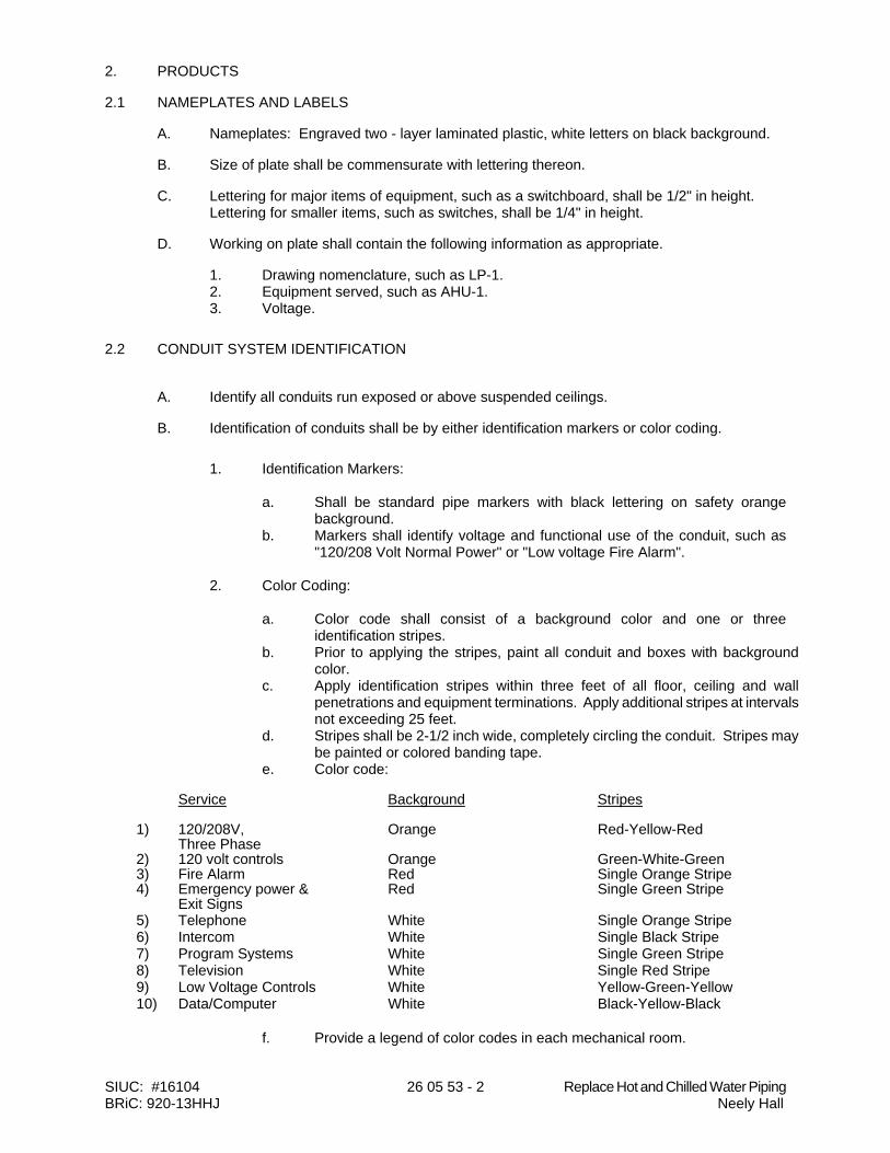
SIUC: #16104 26 05 53 - 2 Replace Hot and Chilled Water Piping BRiC: 920-13HHJ Neely Hall
2. PRODUCTS
2.1 NAMEPLATES AND LABELS
A. Nameplates: Engraved two - layer laminated plastic, white letters on black background.
B. Size of plate shall be commensurate with lettering thereon.
C. Lettering for major items of equipment, such as a switchboard, shall be 1/2" in height. Lettering for smaller items, such as switches, shall be 1/4" in height.
D. Working on plate shall contain the following information as appropriate.
1. Drawing nomenclature, such as LP-1. 2. Equipment served, such as AHU-1. 3. Voltage.
2.2 CONDUIT SYSTEM IDENTIFICATION
A. Identify all conduits run exposed or above suspended ceilings.
B. Identification of conduits shall be by either identification markers or color coding.
1. Identification Markers:
a. Shall be standard pipe markers with black lettering on safety orange
background. b. Markers shall identify voltage and functional use of the conduit, such as
"120/208 Volt Normal Power" or "Low voltage Fire Alarm".
2. Color Coding:
a. Color code shall consist of a background color and one or three identification stripes.
b. Prior to applying the stripes, paint all conduit and boxes with background color.
c. Apply identification stripes within three feet of all floor, ceiling and wall penetrations and equipment terminations. Apply additional stripes at intervals not exceeding 25 feet.
d. Stripes shall be 2-1/2 inch wide, completely circling the conduit. Stripes may be painted or colored banding tape.
e. Color code: Service Background Stripes
1) 120/208V, Orange Red-Yellow-Red
Three Phase 2) 120 volt controls Orange Green-White-Green 3) Fire Alarm Red Single Orange Stripe 4) Emergency power & Red Single Green Stripe
Exit Signs 5) Telephone White Single Orange Stripe 6) Intercom White Single Black Stripe 7) Program Systems White Single Green Stripe 8) Television White Single Red Stripe 9) Low Voltage Controls White Yellow-Green-Yellow 10) Data/Computer White Black-Yellow-Black
f. Provide a legend of color codes in each mechanical room.

SIUC: #16104 26 05 53 - 3 Replace Hot and Chilled Water Piping BRiC: 920-13HHJ Neely Hall
2.3 WIRE IDENTIFICATION
A. Provide wire markers on each conductor in panelboard gutters, pull boxes, outlet and junction boxes, and at load connection. Identify with branch circuit or feeder number for power and lighting circuits, and with control wire number as indicated on schematic and interconnection diagrams and equipment manufacturer's shop drawings for control wiring.
B. Wire Insulation Color:
120/208V 3 Phase Phase A Black Phase B Red Phase C Blue Neutral White
Equipment Ground Green
C. Code all wire and cable larger than color coded sizes available from manufacturer by application of electrical plastic tape in colors specified. Apply tape in uniform manner circling wire or cable. Half-lap tape for length of cable as required by Local Authorities or NEC. Tape shall be 3M, Plymouth or Permacel.
D. Maintain consistent coding throughout installation to ensure proper phase and system identification.
E. Control wiring may use numbered or lettered marker tape. Record wiring so marked on project documents. Marker tape shall be 3M Scotch Code, Panduit Insta-Code, T & B E-Z, Stranco Tuff-Code, Bradypack or Electrovert.
F. Wire insulation color coding and identification means shall be permanently posted and readily visible with the panel door open at each branch-circuit panelboard or similar branch-circuit distribution equipment per NEC 210.5(C).
3. EXECUTION
3.1 PREPARATION
A. Degrease and clean surfaces to receive nameplates and labels.
3.2 APPLICATION
A. Install nameplate and label parallel to equipment lines.
B. Secure nameplate to equipment front using screws, rivets, or adhesive.
C. Secure nameplate to inside surface of door on panelboard that is recessed in finished locations.
D. Paint colored band on each conduit longer than 6 feet.
END OF SECTION
SIUC: #16104 26 2416 - 1 Replace Hot and Chilled Water Piping BRiC: 920-13HHJ Neely Hall
DIVISION 26 - ELECTRICAL Section 26 24 16 - Panelboards
1. GENERAL 1.1 WORK INCLUDES
A. Base Bid:
1. Electrical Contractor Provide:
a. Branch circuit panelboards and circuit breakers.
B. Alternate Bid 1:
1. Electrical Contractor Provide:
a. Circuit breakers. 1.2 REFERENCES
A. NECA (National Electrical Contractors Association) "Standard of Installation." B. NEMA AB 1 - Molded Case Circuit Breakers. C. NEMA ICS 2 - Industrial Control Devices, Controllers, and Assemblies. D. NEMA KS 1 - Enclosed Switches. E. NEMA PB 1 - Panelboards. F. NEMA PB 1.1 - Instructions for Safe Installation, Operation and Maintenance of
Panelboards Rated 600 Volts or Less. G. 2011 Edition of NFPA 70 - National Electrical Code.
1.3 SUBMITTALS
A. Submit under provisions of Section 01 33 23. B. Shop Drawings: Indicate outline and support point dimensions, voltage, main bus capacity,
integrated short circuit ampere rating, circuit breaker and fusible switch arrangement and sizes.
C. Manufacturer's Installation Instructions: Indicate application conditions and limitations of
use stipulated by Product testing agency. Include instructions for storage, handling, protection, examination, preparation, installation, and starting of Product.
1.4 PROJECT RECORD DOCUMENTS
A. Submit under provisions of Section 01 78 39. B. Record actual locations of Products; indicate actual branch circuit arrangement in the typed
circuit directory for the panelboards. This circuit information shall include any room number changes or room changes.
C. Where adjustable trip breakers are provided the manufacturer shall provide the trip settings
SIUC: #16104 26 2416 - 2 Replace Hot and Chilled Water Piping BRiC: 920-13HHJ Neely Hall
for each breaker. 1.5 OPERATION AND MAINTENANCE DATA
A. Submit under provisions of Section 01 78 23 B. Maintenance Data: Include spare parts data listing; source and current prices of
replacement parts and supplies; and recommended maintenance procedures and intervals.
1.6 QUALITY ASSURANCE
A. Perform Work in accordance with NECA Standard of Installation.
1.7 QUALIFICATIONS
A. Manufacturer: Company specializing in manufacturing the Products specified in this section with minimum three years documented experience.
1.8 REGULATORY REQUIREMENTS
A. Conform to requirements of NFPA 70. B. Furnish products listed and classified Independent Testing Laboratory suitable for purpose
specified and indicated. 1.9 FIELD MEASUREMENTS
A. Verify that field measurements are as indicated on shop drawings.
2. PRODUCTS 2.1 BRANCH CIRCUIT PANELBOARDS
A. MANUFACTURERS
1. Square D. 2. Siemens 3. General Electric
B. Lighting and Appliance Branch Circuit Panelboards: NEMA PB1, circuit breaker type. C. Panelboard Bus: Copper ratings as indicated. Provide copper ground bus in each
panelboard. D. Minimum integrated short circuit rating: Shall be greater than as indicated on panel
schedules. E. Molded Case Circuit Breakers: NEMA AB 1, bolt-on type thermal magnetic trip circuit
breakers, with common trip handle for all poles. Provide circuit breakers listed as Type SWD for lighting circuits. Provide UL Class A ground fault interrupter circuit breakers where scheduled. Do not use tandem circuit breakers.
F. Enclosure: NEMA PB 1, Type 1. G. Cabinet Front: Flush or surface (as indicated) cabinet front with concealed trim clamps,
concealed hinge, and flush lock all keyed alike. Finish in manufacturer's standard gray enamel.
H. Size not to exceed 21" wide x 6" deep.
SIUC: #16104 26 2416 - 3 Replace Hot and Chilled Water Piping BRiC: 920-13HHJ Neely Hall
1. All locks shall be GE 75.
3. EXECUTION 3.1 INSTALLATION
A. Install panelboards in accordance with NEMA PB 1.1. B. Install panelboards plumb. Provide supports in accordance with Section 26 05 29. C. Height: 6 ft to top of panelboard; install panelboards taller than 6 ft with bottom no more
than 4 inches above floor. D. Provide filler plates for unused spaces in panelboards. E. Provide typed circuit directory for each branch circuit panelboard. Include information for
the load that is served by each breaker. Revise directory to reflect circuiting changes required to balance phase loads and any other circuit changes made during construction.
F. Provide engraved plastic nameplates under the provisions of Section 26 05 53.
3.2 FIELD QUALITY CONTROL
A. Field inspection and testing will be performed. B. Measure steady state load currents at each panelboard feeder; rearrange circuits in the
panelboard to balance the phase loads to within 20 percent of each other. Maintain proper phasing for multi-wire branch circuits.
C. Visual and Mechanical Inspection: Inspect for physical damage, proper alignment,
anchorage, and grounding. Check proper installation and tightness of connections for circuit breakers, fusible switches, and fuses.
END OF SECTION

SIUC: #16104 26 28 16 - 1 Replace Hot and Chilled Water Piping BRiC: 920-13HHJ Neely Hall
DIVISION 26 - ELECTRICAL Section 26 28 16 - Enclosed Switches 1. GENERAL 1.1 WORK INCLUDES
A. Base Bid:
1. Electrical Contractor Provide:
a. Fusible switches. b. Nonfusible switches. c. Fuses.
B. Alternate Bid 1:
1. Electrical Contractor Provide:
a. Fusible switches. b. Nonfusible switches. c. Fuses.
1.2 REFERENCES
A. NEMA KS 1 - Enclosed Switches.
B. 2011 Edition of NFPA 70 - National Electrical Code.
1.3 SUBMITTALS
A. Submit under provisions of 01 33 23
B. Product Data: Provide switch ratings and enclosure dimensions.
C. Manufacturer's Instructions: Indicate application conditions and limitations of use stipulated by Product testing agency specified under Regulatory Requirements. Include instructions for storage, handling, protection, examination, preparation, installation, and starting of Product.
1.4 QUALITY ASSURANCE
A. Perform Work in accordance with NECA Standard of Installation.
1.5 QUALIFICATIONS
A. Manufacturer: Company specializing in manufacturing Products specified in this Section with minimum three years documented experience.
1.6 REGULATORY REQUIREMENTS
A. Conform to requirements of NFPA 70.
B. Furnish products listed and classified Independent Testing Laboratory for purpose specified and shown.
SIUC: #16104 26 28 16 - 2 Replace Hot and Chilled Water Piping BRiC: 920-13HHJ Neely Hall
2. PRODUCTS
2.1 MANUFACTURERS
A. Square D.
B. Siemens.
C. General Electric
2.2 ENCLOSED SWITCHES
A. Fusible Switch Assemblies: NEMA KS 1, Type HD load interrupter enclosed knife switch with externally operable handle interlocked to prevent opening front cover with switch in ON position. Handle lockable in OFF position. Fuse clips: Designed to accommodate Class R fuses.
B. Nonfusible Switch Assemblies: NEMA KS 1, Type HD load interrupter enclosed knife switch with externally operable handle interlocked to prevent opening front cover with switch in ON position. Handle lockable in OFF position.
C. Enclosures: NEMA KS 1.
1. Interior Dry Locations: Type 1. 2. Exterior Locations: Type 3R.
2.3 FUSES
A. Manufacturers:
1. Bussman. 2. Gould. 3. Little Fuse.
B. Description: Dual element, current limiting, time delay, one-time fuse, 600 volt (480V Operation)or 250V (208V Operation, NRTL Class RK 1.)
C. Interrupting Rating: 200,000 rms amperes.
3. EXECUTION
3.1 INSTALLATION
A. Install disconnect switches where indicated.
B. Install fuses in fusible disconnect switches.
C. Provide adhesive label on inside door of each switch indicating UL fuse class and size for replacement.
END OF SECTION
SIUC: #16104 26 29 13 - 1 Replace Hot and Chilled Water Piping BRiC: 920-13HHJ Neely Hall
DIVISION 26 - ELECTRICAL Section 26 29 13 - Enclosed Motor Controllers
1. GENERAL
1.1 WORK INCLUDES
A. Base Bid:
1. Electrical Contractor Provide:
a. Power wiring to starter when provided as integral part of equipment specified, to motor when starter provided by Electrical Contractor.
b. Starters specified and shown on electrical drawings. c. Disconnects required in accord with NEC. d. Control and interlock wiring specified and shown on electrical drawings.
1.2 REFERENCES
A. 2011 Edition of NFPA 70 - National Electrical Code.
B. NEMA AB 1 - Molded Case Circuit Breakers.
C. NEMA ICS 2 - Industrial Control Devices, Controllers, and Assemblies.
D. NEMA ICS 6 - Enclosures for Industrial Controls and Systems.
E. NEMA KS 1 - Enclosed Switches.
1.3 SUBMITTALS
A. Submit product data in accordance with 01 33 23.
B. Product Data: Provide catalog sheets showing voltage, controller size, ratings and size of switching and overcurrent protective devices, short circuit ratings, dimensions, and enclosure details. For each motor indicated on the plans, indicate motor to be fed by starter on submittal.
C. Test Reports: Indicate field test and inspection procedures and test results.
D. Manufacturer's Installation Instructions: Indicate application conditions and limitations of use stipulated by Product testing agency specified under Regulatory Requirements. Include instructions for storage, handling, protection, examination, preparation, installation, and starting of Product.
1.4 OPERATION AND MAINTENANCE DATA
A. Submit O & M manuals in accordance with Section 01 78 23.
B. Maintenance Data: Include spare parts data listing; source and current prices of replacement parts and supplies; and recommended maintenance procedures and intervals.
1.5 QUALITY ASSURANCE
A. Perform Work in accordance with NECA Standard of Installation.
SIUC: #16104 26 29 13 - 2 Replace Hot and Chilled Water Piping BRiC: 920-13HHJ Neely Hall
1.6 QUALIFICATIONS
A. Manufacturer: Company specializing in manufacturing the Products specified in this section with minimum three years documented experience.
1.7 REGULATORY REQUIREMENTS
A. Conform to requirements of NFPA 70.
B. Furnish products listed and classified by a Nationally Recognized Testing Laboratory NRTL as suitable for purpose specified and indicated.
2. PRODUCTS
2.1 MANUFACTURERS
A. Square-D.
B. Siemens.
C. General Electric
2.2 MANUAL CONTROLLERS
A. Manual Motor Controller: NEMA ICS 2, AC general-purpose Class A manually operated, full-voltage controller with overload element, red pilot light, NO, NC auxiliary contact, and push button operator.
B. Fractional Horsepower Manual Controller: NEMA ICS 2, AC general-purpose Class A manually operated, full-voltage controller for fractional horsepower induction motors, with thermal overload unit, red pilot light, and toggle operator.
C. Motor Starting Switch: NEMA ICS 2, AC general-purpose Class A manually operated, full-voltage controller for induction motors, without thermal overload unit, with red pilot light and toggle operator. Minimum horsepower rating to feed motors designated.
D. Enclosure: NEMA ICS 6; Type 1 or flush mounted were indicated on the drawings.
2.3 AUTOMATIC CONTROLLERS
A. Magnetic Motor Controllers: NEMA ICS 2, AC general-purpose Class A magnetic controller for induction motors rated in horsepower.
B. All combination starter units shall utilize fusible switches. Fusible switches shall be quick make, quick break and shall accept Class R dimension fuses.
C. Line voltage starters shall be electrically operated, electrically held, three pole assemblies with arc extinguishing characteristics and shall have silver-to-silver renewable contacts.
D. Overload Relays: The overload relay assembly shall be of the thermal bimetallic type. Overload relays shall be reset from outside the enclosure by means of an insulated button. The overload relay shall have a built-in push-to-test button.
E. Enclosure: NEMA ICS 6, Type 1.
2.4 PRODUCT OPTIONS AND FEATURES
A. Provide options and features as indicated on the drawings.
SIUC: #16104 26 29 13 - 3 Replace Hot and Chilled Water Piping BRiC: 920-13HHJ Neely Hall
B. Auxiliary Contacts: NEMA ICS 2, rated 10A at 600 V AC. Provide one N.O. and one N.C. contact minimum for each automatic controller.
C. Indicating Lights: Transformer type. Provide green �run� and red �stop� lights for each starter.
D. Selector Switches: Rotary type. Provide Hand-Off-Auto switches for each automatic controller.
E. Relays: NEMA ICS 2, 120 V. Provide as indicated on the drawings. Where a relay is indicated for control of a motor, contacts shall be rated for 20 amps.
F. Control Power Transformers: Each motor control unit shall be provided with a 120 volt secondary, 480 volt or 208V primary control power transformer, sized as recommended by the motor control center supplier. Overcurrent protection shall be provided on primary and secondary of transformer.
2.5 DISCONNECTS
A. Combination Controllers: Combine motor controllers with fusible switch disconnect in common enclosure.
B. Nonfusible Switch Assemblies: NEMA KS 1, enclosed knife switch with externally operable handle.
2.6 FUSES
A. Manufacturers:
1. Bussmann 2. (IL) Little Fuse 3. Gould
B. Description: Dual element, current limiting, time delay, one-time fuse, 600 volt, UL 198E, Class RK 1.
C. Interrupting Rating: 200,000 rms amperes.
3. EXECUTION
3.1 INSTALLATION
A. Install enclosed controllers where indicated, in accordance with manufacturer's instructions.
B. Install enclosed controllers plumb. Provide supports in accordance with Section 26 05 29.
C. Height: 5 ft to operating handle.
D. Install fuses in fusible switches.
E. Select and install overload heater elements in motor controllers to match installed motor characteristics.
F. Provide engraved plastic nameplates under the provisions of Section 26 05 53.
G. Provide neatly typed label inside each motor controller door identifying motor served, nameplate horsepower, full load amperes, code letter, service factor, and voltage/phase rating.
SIUC: #16104 26 29 13 - 4 Replace Hot and Chilled Water Piping BRiC: 920-13HHJ Neely Hall
3.2 FIELD QUALITY CONTROL
A. Field inspection and testing will be performed.
B. Inspect and test each enclosed controller to NEMA ICS 2.
END OF SECTION