Embed Size (px)
Citation preview
SECTION 23 64 26 Page 1
SECTION 23 64 26
CHILLED, CHILLED-HOT, AND CONDENSER WATER PIPING SYSTEMS
PART 1 GENERAL
1.1 REFERENCES
The publications listed below form a part of this specification to the extent referenced. The publications are referred to within the text by the basic designation only.
AMERICAN SOCIETY OF SANITARY ENGINEERING (ASSE)
ASSE 1003 (2001; Errata, 2003) Performance Requirements for Water Pressure Reducing Valves
ASSE 1017 (2003; Errata 2004) Temperature Actuated Mixing Valves for Hot Water Distribution Systems
AMERICAN WATER WORKS ASSOCIATION (AWWA)
AWWA C606 (2006) Grooved and Shouldered Joints
AMERICAN WELDING SOCIETY (AWS)
AWS A5.8/A5.8M (2004; Errata 2004) Specification for Filler Metals for Brazing and Braze Welding
AWS BRH (2007) Brazing Handbook
AWS D1.1/D1.1M (2008) Structural Welding Code - Steel
AWS Z49.1 (2005) Safety in Welding, Cutting and Allied Processes
ASME INTERNATIONAL (ASME)
ASME B1.20.1 (1983; R 2006) Pipe Threads, General Purpose (Inch)
ASME B16.1 (2005) Standard for Gray Iron Threaded Fittings; Classes 125 and 250
ASME B16.11 (2005) Forged Fittings, Socket-Welding and Threaded
ASME B16.18 (2001; R 2005) Cast Copper Alloy Solder Joint Pressure Fittings
ASME B16.21 (2005) Nonmetallic Flat Gaskets for Pipe Flanges

SECTION 23 64 26 Page 2
ASME B16.22 (2001; R 2005) Standard for Wrought Copper and Copper Alloy Solder Joint Pressure Fittings
ASME B16.26 (2006) Standard for Cast Copper Alloy Fittings for Flared Copper Tubes
ASME B16.3 (2006) Malleable Iron Threaded Fittings, Classes 150 and 300
ASME B16.39 (1998; R 2006) Standard for Malleable Iron Threaded Pipe Unions; Classes 150, 250, and 300
ASME B16.5 (2003) Standard for Pipe Flanges and Flanged Fittings: NPS 1/2 Through NPS 24
ASME B16.9 (2007) Standard for Factory-Made Wrought Steel Buttwelding Fittings
ASME B18.2.2 (1987; R 2005) Standard for Square and Hex Nuts
ASME B31.9 (2004) Building Services Piping
ASME B36.10M (2004) Standard for Welded and Seamless Wrought Steel Pipe
ASME B40.100 (2006) Pressure Gauges and Gauge Attachments
ASTM INTERNATIONAL (ASTM)
ASTM A 105/A 105M (2005) Standard Specification for Carbon Steel Forgings for Piping Applications
ASTM A 106/A 106M (2008) Standard Specification for Seamless Carbon Steel Pipe for High-TemperatureService
ASTM A 181/A 181M (2006) Standard Specification for Carbon Steel Forgings, for General-Purpose Piping
ASTM A 183 (2003) Standard Specification for Carbon Steel Track Bolts and Nuts
ASTM A 193/A 193M (2007) Standard Specification for Alloy-Steeland Stainless Steel Bolting Materials for High-Temperature Service
ASTM A 194/A 194M (2007) Standard Specification for Carbon and Alloy Steel Nuts for Bolts for High-Pressureor High-Temperature Service, or Both
ASTM A 197/A 197M (2000; R 2006) Standard Specification for Cupola Malleable Iron
SECTION 23 64 26 Page 3
ASTM A 234/A 234M (2007) Standard Specification for Piping Fittings of Wrought Carbon Steel and Alloy Steel for Moderate and High Temperature Service
ASTM A 325 (2007a) Standard Specification for Structural Bolts, Steel, Heat Treated, 120/105 ksi Minimum Tensile Strength
ASTM A 47/A 47M (1999; R 2004) Standard Specification for Steel Sheet, Aluminum-Coated, by the Hot-DipProcess
ASTM A 53/A 53M (2007) Standard Specification for Pipe, Steel, Black and Hot-Dipped, Zinc-Coated,Welded and Seamless
ASTM A 536 (1984; R 2004) Standard Specification for Ductile Iron Castings
ASTM A 653/A 653M (2008) Standard Specification for Steel Sheet, Zinc-Coated (Galvanized) or Zinc-IronAlloy-Coated (Galvannealed) by the Hot-DipProcess
ASTM A 733 (2003) Standard Specification for Welded and Seamless Carbon Steel and Austenitic Stainless Steel Pipe Nipples
ASTM B 117 (2007a) Standing Practice for Operating Salt Spray (Fog) Apparatus
ASTM B 32 (2004) Standard Specification for Solder Metal
ASTM B 42 (2002e1) Standard Specification for Seamless Copper Pipe, Standard Sizes
ASTM B 62 (2002) Standard Specification for Composition Bronze or Ounce Metal Castings
ASTM B 75 (2002) Standard Specification for Seamless Copper Tube
ASTM B 813 (2000e1) Standard Specification for Liquid and Paste Fluxes for Soldering of Copper and Copper Alloy Tube
ASTM B 88 (2003) Standard Specification for Seamless Copper Water Tube
ASTM D 1384 (2005e1) Corrosion Test for Engine Coolants in Glassware
ASTM D 2000 (2008) Standard Classification System for Rubber Products in Automotive Applications
SECTION 23 64 26 Page 4
ASTM D 3308 (2006) PTFE Resin Skived Tape
ASTM D 520 (2000; R 2005) Zinc Dust Pigment
ASTM D 596 (2001; R 2006) Reporting Results of Analysis of Water
ASTM E 84 (2008a) Standard Test Method for Surface Burning Characteristics of Building Materials
ASTM F 1007 (1986; R 2007) Pipeline Expansion Joints of the Packed Slip Type for Marine Application
ASTM F 104 (2003) Standard Classification System for Nonmetallic Gasket Materials
ASTM F 1120 (1987; R 2004) Standard Specification for Circular Metallic Bellows Type Expansion Joints for Piping Applications
ASTM F 1199 (1988; R 2004) Cast (All Temperatures and Pressures) and Welded Pipe Line Strainers (150 psig and 150 degrees F Maximum)
CSA AMERICA, INC. (CSA/AM)
CSA/AM Z21.22 (1999; R 2004; A 2000, 2001; R 2004) Relief Valves for Hot Water Supply Systems
CSA/ANSI Z21.22 (1999; Addenda A 2000; Addenda B 2001; R 2004) Relief Valves for Hot Water Supply Systems
EXPANSION JOINT MANUFACTURERS ASSOCIATION (EJMA)
EJMA Stds (2003) EJMA Standards
HYDRAULIC INSTITUTE (HI)
HI 1.1-1.5 (1994) Centrifugal Nomenclature
MANUFACTURERS STANDARDIZATION SOCIETY OF THE VALVE AND FITTINGS INDUSTRY (MSS)
MSS SP-110 (1996) Ball Valves Threaded, Socket-Welding,Solder Joint, Grooved and Flared Ends
MSS SP-25 (1998) Standard Marking System for Valves, Fittings, Flanges and Unions
MSS SP-58 (2002) Standard for Pipe Hangers and Supports - Materials, Design and Manufacture
MSS SP-67 (2002a; R 2004) Standard for Butterfly Valves
MSS SP-69 (2003; R 2004) Standard for Pipe Hangers and Supports - Selection and Application
SECTION 23 64 26 Page 5
MSS SP-70 (2006) Standard for Cast Iron Gate Valves,Flanged and Threaded Ends
MSS SP-71 (2005) Standard for Gray Iron Swing Check Valves, Flanged and Threaded Ends
MSS SP-72 (1999) Standard for Ball Valves with Flanged or Butt-Welding Ends for General Service
MSS SP-78 (2005a) Cast Iron Plug Valves, Flanged and Threaded Ends
MSS SP-80 (2003) Bronze Gate, Globe, Angle and Check Valves
MSS SP-85 (2002) Standard for Cast Iron Globe & AngleValves, Flanged and Threaded Ends
NATIONAL ELECTRICAL MANUFACTURERS ASSOCIATION (NEMA)
NEMA 250 (2003) Enclosures for Electrical Equipment (1000 Volts Maximum)
NEMA MG 1 (2007; Errata 2008) Standard for Motors and Generators
NEMA MG 11 (1977; R 2007) Energy Management Guide for Selection and Use of Single Phase Motors
NATIONAL FIRE PROTECTION ASSOCIATION (NFPA)
NFPA 90A (2008) Standard for the Installation of Air Conditioning and Ventilating Systems
U.S. GENERAL SERVICES ADMINISTRATION (GSA)
CID A-A-50541 (Basic; Notice 1) Valves, Tank Float, Angle and Globe Pattern (Inch-Pound
1.2 SYSTEM DESCRIPTION
Provide the water systems having the minimum service (design) temperature-pressure rating indicated. Provision of the piping systems, including materials, installation, workmanship, fabrication, assembly, erection, examination, inspection, and testing shall be in accordance with the required and advisory provisions of ASME B31.9 except as modified or supplemented by this specification section or design drawings. This specification section covers the water systems piping which is located within, on, and adjacent to building(s) within the building(s) 5 foot line.
1.3 SUBMITTALS
Government approval is required for submittals with a "G" designation; submittals not having a "G" designation are for Contractor Quality Control approval for information only. When used, a designation following the "G" designation identifies the office that will review the submittal for the
SECTION 23 64 26 Page 6
Government. Submit the following submitted in accordance with Section 01 33 00 SUBMITTAL PROCEDURES:
SD-03 Product Data
Grooved Mechanical Connections For Steel; GGrooved Mechanical Connections For Copper; GCalibrated Balancing Valves; GAutomatic Flow Control Valves; GPump Discharge ValveWater Temperature Mixing Valve; GWater Temperature Regulating Valves; GWater Pressure Reducing ValvePressure Relief ValveCombination Pressure and Temperature Relief ValvesExpansion Joints; GPumps; GCombination Strainer and Pump Suction DiffuserExpansion TanksAir Separator TanksWater Treatment Systems; G
Proposed water treatment plan including a layout, control scheme, a list of existing make-up water conditions including the items listed in paragraph "Water Analysis", a list of chemicals, the proportion of chemicals to be added, the final treated water conditions, and a description of environmental concerns for handling the chemicals.
SD-06 Test Reports
Piping welds NDE reportPressure tests reports; G
Report shall be provided in bound 8 1/2 by 11 inch booklets. In the reports, document all phases of the tests performed. Include initial test summaries, all repairs/adjustments made, and the final test results.
Condenser Water Quality Test Reports; G
Test reports, each month for a period of one year after project completion, in bound 8-1/2 by 11 inch booklets. In the reports, identify the chemical composition of the condenser water. Also include the comparison of the manufacturer's recommended operating conditions for the cooling tower and condenser in relation to the condition of the condenser water. Document in the report any required corrective action taken.
One-Year Inspection Report For Cooling Water; G
At the completion of one year of service, in bound 8-1/2 by 11 inch booklets. In the report, identify the condition of each cooling tower and condenser. Include a comparison of the condition of the cooling tower and condenser with the manufacturer's recommended operating conditions. Identify all actions taken by
SECTION 23 64 26 Page 7
the Contractor and manufacturer to correct deficiencies during the first year of service.
SD-07 Certificates
Employer's Record Documents (For Welding)Welding Procedures and Qualifications
Certificates shall be submitted for the following items showing conformance with the referenced standards contained in this section.
Piping for Steam and CondensatePiping for High-Pressure Compressed-Air SystemsFittingsUnionsFlangesGasketsBolting
SD-08 Manufacturer's Instructions
Lesson plan for the Instruction Course; G
SD-10 Operation and Maintenance Data
Requirements for data packages are specified Section 01 78 23OPERATION AND MAINTENANCE DATA, except as supplemented and modified by this specification section.
Submit spare parts data for each different item of equipment specified, with operation and maintenance data packages. Include a complete list of parts and supplies, with current unit prices and source of supply, a recommended spare parts list for 1 year of operation, and a list of the parts recommended by the manufacturer to be replaced on a routine basis.
Submit a list of qualified permanent service organizations with operation and maintenance data packages. Include service organization addresses and service area or expertise. The service organizations shall be reasonably convenient to the equipment installation and be able to render satisfactory service to the equipment on a regular and emergency basis during the warranty period of the contract.
Water Treatment Systems; G
Submit one electronic (.pdf) version and 2 hard copies of an operation manual in bound 8 1/2 by 11 inch booklets listing step-by-step procedures required for system startup, operation, abnormal shutdown, emergency shutdown, and normal shutdown. Include testing procedures used in determining water quality.
Submit one electronic (.pdf) version and 2 hard copies of a maintenance manual in bound 8 1/2 by 11 inch booklets listing routine maintenance procedures, possible breakdowns and repairs, and a trouble shooting guide.
SECTION 23 64 26 Page 8
Calibrated Balancing Valves, Data Package 3; G
Automatic Flow Control Valves, Data Package 3; G
Pump Discharge Valve, Data Package 2; G
Water Temperature Mixing Valve, Data Package 3; G
Water Temperature Regulating Valves, Data Package 3; G
Water Pressure Reducing Valve, Data Package 3; G
Pressure Relief Valve, Data Package 2; G
Combination Pressure and Temperature Relief Valves, Data Package 2; G
Expansion Joints, Data Package 2; G
Pumps, Data Package 3; G
Combination Strainer and Pump Suction Diffuser, Data Package 2; G
Expansion Tanks, Data Package 2; G
Air Separator Tanks, Data Package 2; G
1.4 MODIFICATIONS TO REFERENCES
In each of the publications referred to herein, consider the advisory provisions to be mandatory, as though the word, "shall" had been substituted for "should" wherever it appears. Interpret references in these publications to the "authority having jurisdiction", or words of similarmeaning, to mean the Contracting Officer.
1.4.1 Definitions
For the International Code Council (ICC) Codes referenced in the contract documents, advisory provisions shall be considered mandatory, the word "should" shall be interpreted as "shall." Reference to the "code official" shall be interpreted to mean the "Contracting Officer." For Navy owned property, references to the "owner" shall be interpreted to mean the "Contracting Officer." For leased facilities, references to the "owner" shall be interpreted to mean the "lessor." References to the "permit holder" shall be interpreted to mean the "Contractor."
1.4.2 Administrative Interpretations
For ICC Codes referenced in the contract documents, the provisions of Chapter 1, "Administrator," do not apply. These administrative requirements are covered by the applicable Federal Acquisition Regulations (FAR) included in this contract and by the authority granted to the Officer in Charge of Construction to administer the construction of this project. References in the ICC Codes to sections of Chapter 1, shall be applied appropriately by the Contracting Officer as authorized by his administrative cognizance and the FAR.
SECTION 23 64 26 Page 9
1.5 SAFETY REQUIREMENTS
Exposed moving parts, parts that produce high operating temperature, parts which may be electrically energized, and parts that may be a hazard to operating personnel shall be insulated, fully enclosed, guarded, or fitted with other types of safety devices. Safety devices shall be installed so that proper operation of equipment is not impaired.
1.6 DELIVERY, STORAGE, AND HANDLING
Protect stored items from the weather, humidity and temperature variations, dirt and dust, or other contaminants. Proper protection and care of all material both before and during installation shall be the Contractor's responsibility. Any materials found to be damaged shall be replaced at the Contractor's expense. During installation, cap piping and similar openings to keep out dirt and other foreign matter. Any porous materials found to be contaminated with mold or mildew will be replaced at the Contractor's expense. Non-porous materials found to be contaminated with mold or mildew will be disinfected and cleaned prior to installation.
1.7 PROJECT/SITE CONDITIONS
1.7.1 Verification of Dimensions
The Contractor shall become familiar with all details of the work, verify all dimensions in the field, and advise the Contracting Officer of any discrepancy before performing any work.
1.7.2 Drawings
Because of the small scale of the drawings, it is not possible to indicate all offsets, fittings, and accessories that may be required. The Contractor shall carefully investigate the plumbing, fire protection, electrical, structural and finish conditions that would affect the work to be performed and shall arrange such work accordingly, furnishing required offsets, fittings, and accessories to meet such conditions.
1.7.3 Accessibility
Install all work so that parts requiring periodic inspection, operation, maintenance, and repair are readily accessible. Install concealed valves, expansion joints, controls, dampers, and equipment requiring access, inlocations freely accessible through access doors.
PART 2 PRODUCTS
2.1 STANDARD COMMERCIAL PRODUCTS
Materials and equipment shall be standard products of a manufacturer regularly engaged in the manufacturing of such products, which are of a similar material, design and workmanship. The standard products shall have been in satisfactory commercial or industrial use for 2 years prior to bid opening.
The 2 year use shall include applications of equipment and materials under similar circumstances and of similar size. The 2 years experience shall be
SECTION 23 64 26 Page 10
satisfactorily completed by a product which has been sold or is offered for sale on the commercial market through advertisements, manufacturer's catalogs, or brochures.
Products having less than a 2 year field service record shall be acceptable if a certified record of satisfactory field operation, for not less than 6,000 hours exclusive of the manufacturer's factory tests, can be shown.System components shall be environmentally suitable for the indicatedlocations.
The equipment items shall be supported by service organizations. These service organizations shall be reasonably convenient to the equipment installation and able to render satisfactory service to the equipment on a regular and emergency basis during the warranty period of the contract.
2.2 STEEL PIPING
Water piping shall be steel pipe or copper tubing. Provide steel piping with a ANSI/ASME Class 125 service rating, which for 150 degrees F, the pressure rating is 175 psig.
2.2.1 Pipe
Steel pipe, conform to ASTM A 53/A 53M, Schedule 40, Type E or S, Grades A or B. Do not use Type F pipe.
2.2.2 Fittings and End Connections (Joints)
Piping and fittings 1 inch and smaller shall have threaded connections.Piping and fittings larger than 1 inch and smaller than 3 inches shall have either threaded, grooved, or welded connections. Piping and fittings 3 inches and larger shall have grooved, welded, or flanged connections. The manufacturer of each fitting shall be permanently identified on the body of the fitting in accordance with MSS SP-25.
2.2.2.1 Threaded Connections
Use threaded valves and pipe connections conforming to ASME B1.20.1. Used threaded fitting conforming to ASME B16.3. Use threaded unions conforming to ASME B16.39. Use threaded pipe nipples conforming to ASTM A 733.
2.2.2.2 Flanged Connections
Flanges shall conform to ASME B16.1, Class 150. Gaskets shall be nonasbestos compressed material in accordance with ASME B16.21, 1/16 inch thickness, full face or self-centering flat ring type. These gaskets shall contain aramid fibers bonded with styrene butadeine rubber (SBR) or nitrile butadeine rubber (NBR). Bolts, nuts, and bolt patterns shall conform to ASME B16.1.
2.2.2.3 Welded Connections
Welded valves and pipe connections (both butt-welds and socket-welds types) shall conform to ASME B31.9. Butt-welded fittings shall conform to ASMEB16.9. Socket-welded fittings shall conform to ASME B16.11. Welded fittings shall be identified with the appropriate grade and marking symbol.
SECTION 23 64 26 Page 11
2.2.2.4 Grooved Mechanical Connections For Steel
Rigid grooved mechanical connections may only be used in serviceable aboveground locations where the temperature of the circulating medium does not exceed 230 degrees F. Flexible grooved connections shall be used only as a flexible connector with grooved pipe system. Unless otherwise specified, grooved piping components shall meet the corresponding criteria specified for the similar welded, flanged, or threaded component specifiedherein.
Each grooved mechanical joint shall be a system, including coupling housing, gasket, fasteners, all furnished by the same manufacturer. Joint installation shall be in compliance with joint manufacturer's written instructions.
Use fitting and coupling houses of malleable iron conforming to ASTM A 47/A 47M, Grade 32510; ductile iron conforming to ASTM A 536, Grade 65-45-12; or steel conforming ASTM A 106/A 106M, Grade B or ASTM A 53/A 53M. Use gaskets of molded synthetic rubber with central cavity, pressure responsive configuration and conforming to ASTM D 2000 Grade No. 2CA615A15B44F17Z for circulating medium up to 230 degrees F or Grade No. M3BA610A15B44Z for circulating medium up to 200 degrees F. Grooved mechanical connections shall conform to AWWA C606. Coupling nuts and bolts shall be steel and shall conform to ASTM A 183. Pipe connections and fittings shall be the product of the same manufacturer. Provide joint installation be in compliance with joint manufacturer's written instructions.
2.2.2.5 Dielectric Waterways and Flanges
Provide dielectric waterways with a water impervious insulation barrier capable of limiting galvanic current to 1 percent of short circuit current in a corresponding bimetallic joint. When dry, insulation barrier shall be able to withstand a 600-volt breakdown test. Provide dielectric waterways constructed of galvanized steel and have threaded end connections to match connecting piping. Dielectric waterways shall be suitable for the required operating pressures and temperatures. Provide dielectric flanges with the same pressure ratings as standard flanges and provide complete electrical isolation between connecting pipe and/or equipment as described herein for dielectric waterways.
2.3 PIPING FOR STEAM AND CONDENSATE
Steam and condensate piping for 150-, 350-, 2,000-, and 6,000-pound per square inch (psi) service shall be black carbon steel (BCS).
2.3.1 Type BCS-150 (150-psi Service)
Pipe or tube (1/8 inch through 10 inches): Schedule 40 for steam, Schedule 80 for condensate, seamless black carbon steel, conforming to ASTM A 106/A 106M, Grade B and ASME B36.10M
Fittings (1/8 inch through 2 inches): 300-psi working steam pressure (wsp) banded malleable iron, screwed end, conforming to ASTM A 197/A 197M and ASMEB16.3
SECTION 23 64 26 Page 12
Fittings (1/8 inch through 2 inches): 2,000-or 3,000-psi water, oil, or gas (wog) forged carbon steel, socket weld or screwed end, conforming to ASTM A 105/A 105M and ASME B16.11
Fittings (2-1/2 through 10 inches): Wall thickness to match pipe, long radius, butt weld, black carbon steel, conforming to ASTM A 234/A 234M,Grade WPB, and ASME B16.9
Unions (1/8 inch through 2 inches): 250-psi wsp, malleable iron, screwed end, ground joint, with brass or bronze seat insert, conforming to ASMEB16.39
Unions (1/8 inch through 2 inches): 2,000 or 3,000-psi wog, forged carbon steel; socket weld through 2-inch, screwed end through 1-inch, conforming to ASTM A 105/A 105M and ASME B16.11, with ground joint and stainless-steelseat insert
Flanges (2-1/2 through 10 inches): 150-pound, forged carbon steel, welding neck, with raised face or flat face and concentric finish, conforming to ASTM A 105/A 105M and ASME B16.5
Flange Gaskets: Compressed non-asbestos sheet conforming to ASTM F 104,Type 1, P1161A, coated on both sides with graphite or similar lubricant, containing not less than 75-percent non-asbestos fiber materials
Bolting: Bolting and flange bolting shall be hexheaded and shall conform to ASTM A 325. Heavy hex-nuts shall conform to ASME B18.2.2. Square-head bolts and nuts are not acceptable.
2.3.2 Type BCS-350 (350-psi Service)
Pipe or tube (1/8 inch through 10 inches): Schedule 40 for steam, Schedule 80 for condensate; seamless black carbon steel, conforming to ASTM A 106/A 106M, Grade B and ASME B36.10M
Fittings (1/8 inch through 2 inches): 2,000-or 3,000-psi wog to match pipe wall, forged carbon steel, socket weld or screwed end, conforming to ASTM A 105/A 105M and ASME B16.11
Fittings (1/8 inch through 10 inches): Schedule 40, long-radius, butt weld, black carbon steel, conforming to ASTM A 234/A 234M, Grade WPB, and ASMEB16.9
Unions (1/8 inch through 2 inches): 2,000-or 3,000-psi wog to match pipe wall, forged carbon steel, socket weld through 2-inch, screwed end through 1-inch, conforming to ASTM A 105/A 105M and ASME B16.11, with ground joint and stainless-steel seat insert
Flanges (2-1/2 through 10 inches): 300-pound, forged carbon steel, weld neck, with raised face and concentric serrated finish, conforming to ASTM A 181/A 181M, Class 70, and ASME B16.5
Gaskets: Spiral-wound, non-asbestos-fiber-filled, carbon steel, with centering provisions, conforming to ASME B16.5, Group 1
Bolting: Heavy hex-head, carbon-steel bolts or bolt studs and semifinishedheavy hexnuts, conforming to ASTM A 325.
SECTION 23 64 26 Page 13
Square-head bolts are not acceptable.
2.4 PIPING FOR HIGH-PRESSURE COMPRESSED-AIR SYSTEMS
2.4.1 Type BCS-2,000 (2,000-psi Service)
Pipe or tube (1/8 inch through 3 inches): Schedule 40, seamless black carbon steel, conforming to ASTM A 106/A 106M, Grade B, or ASTM A 53/A 53M,Grade B, Type S, and ASME B36.10M
Fittings (1/8 inch through 1-1/2 inches): 2,000-psi wog, forged carbon steel, socket weld, conforming to ASTM A 105/A 105M and ASME B16.11
Fittings (2 through 3 inches): Schedule 40, long radius, butt weld, black carbon steel, conforming to ASTM A 234/A 234M, Grade WPB, and ASME B16.9
Flanges (1 inch through 3 inches): 900-pound, forged carbon steel, welding neck, with raised face and concentric serrated finish, conforming to ASTM A 105/A 105M or ASTM A 181/A 181M, Class 60, and ASME B16.5
Gaskets: Spiral wound, non-asbestos-fiber-filled, carbon steel, with centering provisions, conforming to ASME B16.5, Group 1
Bolting: Alloy-steel bolt studs conforming to ASTM A 193/A 193M, Grade B7, and semifinished heavy hex-nuts, conforming to ASTM A 194/A 194M, Grade 2H
2.4.2 Type BCS-6,000 (6,000-psi Service)
Pipe or tube (1/2 inch through 3 inches): XXS, seamless, black carbon steel, conforming to ASTM A 106/A 106M, Grade B, or ASTM A 53/A 53M, Grade B, Type S and ASME B36.10M
Fittings (1/2 inch through 1-1/2 inches): 6,000-psi wog, forged carbon steel, socket weld, conforming to ASTM A 105/A 105M and ASME B16.11
Fittings (2 through 3 inches): XXS, long-radius, butt weld, black carbon steel, conforming to ASTM A 234/A 234M, Grade WPB, ASME B16.9, and ASMEB36.10M
Flanges (2 through 3 inches): 2,500-pound, forged carbon steel, welding neck with raised face and concentric serrated finish, conforming to ASTM A 105/A 105M and ASME B16.5
Gaskets: Spiral-wound, non-asbestos-filled, carbon steel, with centering provisions, conforming to ASME B16.5, Group 1
Bolting: Alloy steel bolt studs conforming to ASTM A 193/A 193M, Grade B7, and semifinished heavy hex-nuts, conforming to ASTM A 194/A 194M, Grade 2H
2.5 COPPER TUBING
Provide copper tubing and fittings with a ANSI/ASME Class 125 service rating, which for 150 degrees F., the pressure rating is 175 psig.
2.5.1 Tube
SECTION 23 64 26 Page 14
Use copper tube conforming to ASTM B 88, Type L or M for aboveground tubing, and Type K for buried tubing.
2.5.2 Fittings and End Connections (Solder and Flared Joints)
Wrought copper and bronze solder joint pressure fittings, including unions and flanges, shall conform to ASME B16.22 and ASTM B 75. Provide adapters as required. Cast copper alloy solder-joint pressure fittings , including unions and flanges, shall conform to ASME B16.18. Cast copper alloy fittings for flared copper tube shall conform to ASME B16.26 and ASTM B 62.ASTM B 42 copper pipe nipples with threaded end connections shall conform toASTM B 42.
Copper tubing of sizes larger than 4 inches shall have brazed joints. Brassor bronze adapters for brazed tubing may be used for connecting tubing to flanges and to threaded ends of valves and equipment.
Extracted brazed tee joints may be used if produced with an acceptable tool and installed in accordance with tool manufacturer's written procedures.
2.5.3 Grooved Mechanical Connections For Copper
Rigid grooved mechanical connections may only be used in serviceable aboveground locations where the temperature of the circulating medium does not exceed 230 degrees F. Flexible grooved connections shall be used only as a flexible connector with grooved pipe system. Unless otherwise specified, grooved piping components shall meet the corresponding criteria specified for the similar welded, flanged, or threaded component specified herein.
Each grooved mechanical joint shall be a system, including coupling housing, gasket, fasteners, all furnished by the same manufacturer. Joint installation shall be in compliance with joint manufacturer's written instructions.
Grooved fitting and mechanical coupling housing shall be ductile iron conforming to ASTM A 536. Provide gaskets for use in grooved joints shall constructed of molded synthetic polymer of pressure responsive design and shall conform to ASTM D 2000 for circulating medium up to 230 degrees F.Provide grooved joints in conformance with AWWA C606.
2.5.4 Solder
Provide solder in conformance with ASTM B 32, grade Sb5, tin-antimony alloy.Solder flux shall be liquid or paste form, non-corrosive and conform to ASTMB 813.
2.5.5 Brazing Filler Metal
Filler metal shall conform to AWS A5.8/A5.8M, Type BAg-5 with AWS Type 3 flux, except Type BCuP-5 or BCuP-6 may be used for brazing copper-to-copperjoints.
2.6 VALVES
Provide valves with a ANSI/ASME Class 125 service rating, which for 150 degrees F, the pressure rating is 175 psig.
SECTION 23 64 26 Page 15
Valves in sizes larger than 1 inch and used on steel pipe systems, may be provided with rigid grooved mechanical joint ends. Such grooved end valves shall be subject to the same requirements as rigid grooved mechanical joints and fittings and, shall be furnished by the same manufacturer as the grooved pipe joint and fitting system.
2.6.1 Gate Valve
Gate valves 2-1/2 inches and smaller shall conform to MSS SP-80 Class 125 and shall be bronze with wedge disc, rising stem and threaded, soldered, or flanged ends. Gate valves 3 inches and larger shall conform to MSS SP-70,Class 125, cast iron with bronze trim, outside screw and yoke, and flanged or threaded ends.
2.6.2 Globe and Angle Valve
Globe and angle valves 2-1/2 inches and smaller shall conform to MSS SP-80,Class 125. Globe and angle valves 3 inches and larger shall conform to MSSSP-85, Class 125.
2.6.3 Check Valve
Check valves 2-1/2 inches and smaller shall conform to MSS SP-80. Check valves 3 inches and larger shall conform to MSS SP-71, Class 125.
2.6.4 Butterfly Valve
Butterfly valves shall conform to MSS SP-67, Type 1 and shall be either the wafer or lug type. Valves smaller than 8 inches shall have throttling handles with a minimum of seven locking positions. Valves 8 inches and larger shall have totally enclosed manual gear operators with adjustable balance return stops and position indicators.
2.6.5 Plug Valve
Plug valves 2 inches and larger shall conform to MSS SP-78, have flanged or threaded ends, and have cast iron bodies with bronze trim. Valves 2 inches and smaller shall be bronze with NPT connections for black steel pipe and brazed connections for copper tubing. Valve shall be lubricated, non-lubricated, or tetrafluoroethylene resin-coated type. Valve shall be resilient, double seated, trunnion mounted with tapered lift plug capable of 2-way shutoff. Valve shall operate from fully open to fully closed by rotation of the handwheel to lift and turn the plug. Valves 8 inches or larger shall be provided with manual gear operators with position indicators.
2.6.6 Ball Valve
Full port design. Ball valves 1/2 inch and larger shall conform to MSS SP-72 or MSS SP-110 and shall be cast iron or bronze with threaded, soldered, or flanged ends. Valves 8 inches or larger shall be provided with manual gear operators with position indicators. Ball valves may be provided in lieu of gate valves.
2.6.7 Square Head Cocks
SECTION 23 64 26 Page 16
Provide copper alloy or cast-iron body with copper alloy plugs, suitable for 125 psig water working pressure.
2.6.8 Calibrated Balancing Valves
Copper alloy or cast iron body, copper alloy or stainless internal working parts. Provide valve calibrated so that flow can be determined when the temperature and pressure differential across valve is known. Valve shall have an integral pointer which registers the degree of valve opening. Valve shall function as a service valve when in fully closed position. Valve shall be constructed with internal seals to prevent leakage and shall be supplied with preformed insulation.
Provide valve bodies with tapped openings and pipe extensions with positive shutoff valves outside of pipe insulation. The pipe extensions shall be provided with quick connecting hose fittings for a portable differential pressure meter connections to verify the pressure differential. Provide metal tag on each valve showing the gallons per minute flow for each differential pressure reading. In lieu of the balancing valve with integral metering connections, a ball valve or plug valve with a separately installed orifice plate or venturi tube may be used for balancing.
2.6.9 Automatic Flow Control Valves
Valve shall automatically maintain the constant flow indicated on the design drawings. Valve shall modulate by sensing the pressure differential across the valve body. Valve shall be selected for the flow required and provided with a permanent nameplate or tag carrying a permanent record of the factory-determined flow rate and flow control pressure levels. Provide valve that controls the flow within 5 percent of the tag rating. Valve materials shall be the same as specified for the ball or plug valves.
Provide valve that are electric or pneumatic type as indicated. Valve shall be capable of positive shutoff against the system pump head, valve bodies shall be provided with tapped openings and pipe extensions with shutoff valves outside of pipe insulation. The pipe extensions shall be provided with quick connecting hose fittings and differential meter, suitable for the operating pressure specified. Provide the meter complete with hoses, vent, integral metering connections, and carrying case as recommended by the valve manufacturer.
2.6.10 Pump Discharge Valve
Valve shall perform the functions of a nonslam check valve, a manual balancing valve, and a shutoff. Valve shall be of cast iron or ductile iron construction with bronze and/or stainless steel accessories. Provide an integral pointer on the valve which registers the degree of valve opening.Flow through the valve shall be manually adjustable from bubble tight shutoff to full flow. Valves smaller than 2 inches shall have NPT connections. Valves 2 inches and larger shall have flanged or grooved end connections. Valve design shall allow the back seat for the stem to be replaced in the field under full line pressure.
2.6.11 Water Temperature Mixing Valve
Valve, ASSE 1017 for water service.
SECTION 23 64 26 Page 17
2.6.12 Water Temperature Regulating Valves
Provide copper alloy body, direct acting, pilot operated, for the intended service.
2.6.13 Water Pressure Reducing Valve
Valve, ASSE 1003 for water service, copper alloy body, automatic re-seating,with test lever.
2.6.14 Pressure Relief Valve
Valve shall prevent excessive pressure in the piping system when the piping system reaches its maximum heat buildup. Valve, CSA/AM Z21.22 and shallhave cast iron bodies with corrosion resistant internal working parts. The discharge pipe from the relief valve shall be the size of the valve outlet unless otherwise indicated.
2.6.15 Combination Pressure and Temperature Relief Valves
CSA/AM Z21.22, copper alloy body, automatic re-seating, test lever, and discharge capacity based on AGA temperature steam rating.
2.6.16 Float Valve
Valve, CID A-A-50541, Style A (angle pattern) and or Style B (globe pattern). Where float rods are extended for tank applications, extension shall be properly supported and guided to avoid bending of float rod or stressing of valve pilot linkage.
2.6.17 Drain Valves
Valves, MSS SP-80 gate valves. Valve shall be manually-operated, 3/4 inch pipe size and above with a threaded end connection. Provide valve with a water hose nipple adapter. Freeze-proof type valves shall be provided in installations exposed to freezing temperatures.
2.6.18 Air Venting Valves
Manually-operated general service type air venting valves, brass or bronze valves that are furnished with threaded plugs or caps. Automatic type air venting shall be the ball-float type with brass/bronze or brass bodies, 300 series corrosion-resistant steel float, linkage and removable seat. Air venting valves on water coils shall have not less than 1/8 inch threaded end connections. Air venting valves on water mains shall have not less than 3/4 inch threaded end connections. Air venting valves on all other applications shall have not less than 1/2 inch threaded end connections.
2.6.19 Vacuum Relief Valves
CSA/ANSI Z21.22.
2.7 PIPING ACCESSORIES
2.7.1 Strainer
SECTION 23 64 26 Page 18
Strainer, ASTM F 1199, except as modified and supplemented in this specification. Strainer shall be the cleanable, basket or "Y" type, the same size as the pipeline. Strainer bodies shall be fabricated of cast iron with bottoms drilled, and tapped. Provide blowoff outlet with pipe nipple, gate valve, and discharge pipe nipple. The bodies shall have arrows clearly cast on the sides indicating the direction of flow.
Provide strainer with removable cover and sediment screen. The screen shallbe made of minimum 22 gauge monel, with small perforations numbering not less than 400 per square inch to provide a net free area through the basket of at least 3.30 times that of the entering pipe. The flow shall be into the screen and out through the perforations.
2.7.2 Cyclonic Separator
Metal- bodied, with removal capability of removing solids 45 microns/325 mesh in size and heavier than 1.20 specific gravity, maximum pressure drop of 5 psi, with cleanout connection.
2.7.3 Combination Strainer and Pump Suction Diffuser
Angle type body with removable strainer basket and internal straightening vanes, a suction pipe support, and a blowdown outlet and plug. Strainer shall be in accordance with ASTM F 1199, except as modified and supplemented by this specification. Unit body shall have arrows clearly cast on the sides indicating the direction of flow.
Strainer screen shall be made of minimum 22 gauge monel, with small perforations numbering not less than 400 per square inch to provide a netfree area through the basket of at least 3.30 times that of the entering pipe. Flow shall be into the screen and out through the perforations. Provide an auxiliary disposable fine mesh strainer which shall be removed 30 days after start-up. Provide warning tag for operator indicating scheduled date for removal.
Casing shall have connection sizes to match pump suction and pipe sizes, and be provided with adjustable support foot or support foot boss to relieve piping strains at pump suction. Provide unit casing with blowdown port and plug. Provide a magnetic insert to remove debris from system.
2.7.4 Flexible Pipe Connectors
Provide flexible bronze or stainless steel piping connectors with single braid. Equip flanged assemblies with limit bolts to restrict maximum travel to the manufacturer's standard limits. Unless otherwise indicated, the length of the flexible connectors shall be as recommended by the manufacturer for the service intended. Internal sleeves or liners, compatible with circulating medium, shall be provided when recommended by the manufacturer. Provide covers to protect the bellows where indicated.
2.7.5 Pressure and Vacuum Gauges
Gauges, ASME B40.100 with throttling type needle valve or a pulsation dampener and shut-off valve. Provide gauges with 4.5 inch dial, brass or aluminum case, bronze tube, and siphon. Gauge shall have a minimum of with a range from 0 psig to approximately 1.5 times the maximum system working
SECTION 23 64 26 Page 19
pressure. Each gauge range shall be selected so that at normal operating pressure, the needle is within the middle-third of the range.
2.7.6 Temperature Gauges
Temperature gauges, shall be the industrial duty type and be provided for the required temperature range. Provide gauges with fixed thread connection, dial face gasketed within the case; and an accuracy within 2 percent of scale range. Gauges shall have Fahrenheit scale in 2 degree graduations scale (black numbers) on a white face. The pointer shall be adjustable. Rigid stem type temperature gauges shall be provided in thermal wells located within 5 feet of the finished floor. Universal adjustable angle type or remote element type temperature gauges shall be provided in thermal wells located 5 to 7 feet above the finished floor or in locations indicated. Remote element type temperature gauges shall be provided in thermal wells located 7 feet above the finished floor or in locations indicated.
2.7.6.1 Stem Cased-Glass
Stem cased-glass case shall be polished stainless steel or cast aluminum, 9 inches long, with clear acrylic lens, and non-mercury filled glass tube with indicating-fluid column.
2.7.6.2 Bimetallic Dial
Bimetallic dial type case shall be not less than 3-1/2 inches, stainless steel, and shall be hermetically sealed with clear acrylic lens. Bimetallic element shall be silicone dampened and unit fitted with external calibrator adjustment.
2.7.6.3 Liquid-, Solid-, and Vapor-Filled Dial
Liquid-, solid-, and vapor-filled dial type cases shall be not less than 3-1/2 inches, stainless steel or cast aluminum with clear acrylic lens. Fill shall be nonmercury, suitable for encountered cross-ambients, and connecting capillary tubing shall be double-braided bronze.
2.7.6.4 Thermal Well
Thermal well shall be identical size, 1/2 or 3/4 inch NPT connection, brass or stainless steel. Where test wells are indicated, provide captive plug-fitted type 1/2 inch NPT connection suitable for use with either engraved stem or standard separable socket thermometer or thermostat. Mercury shall not be used in thermometers. Extended neck thermal wells shall be of sufficient length to clear insulation thickness by 1 inch.
2.7.7 Pipe Hangers, Inserts, and Supports
Pipe hangers, inserts, guides, and supports: to MSS SP-58 and MSS SP-69.
2.7.8 Escutcheons
Provide one piece or split hinge metal plates for piping entering floors, walls, and ceilings in exposed spaces. Secure plates in place by internal spring tension or set screws. Provide polished stainless steel plates or
SECTION 23 64 26 Page 20
chromium-plated finish on copper alloy plates in finished spaces. Provide paint finish on metal plates in unfinished spaces.
2.7.9 Expansion Joints
2.7.9.1 Slip-Tube Type
Slip-tube expansion joints, ASTM F 1007, Class I or II. Joints shall be provided with internally-externally alignment guides, injected semi-plasticpacking, and service outlets. End connections shall be flanged or beveled for welding as indicated. Initial settings shall be made in accordance with the manufacturer's recommendations to compensate for ambient temperature at time of installation. Pipe alignment guides shall be installed as recommended by the joint manufacturer.
2.7.9.2 Flexible Ball Type
Flexible ball expansion joints shall be capable of 360 degrees rotation plus 15 degrees angular flex movement. Joints shall be constructed of carbon steel with the exterior spherical surface of carbon steel balls plated with a minimum 5 mils of hard chrome in accordance with EJMA Stds. Joint end connections shall be threaded for piping 2 inches or smaller. Joint end connections larger than 2 inches shall be grooved, flanged, or beveled for welding. Provide joint with pressure-molded composition gaskets suitable for continuous operation at twice design temperature.
2.7.9.3 Bellows Type
Bellows expansion type joints, ASTM F 1120 with Type 304 stainless steel corrugated bellows, reinforced with equalizing rings, internal sleeves, and external protective covers. Joint end connections shall be grooved, flanged, or beveled for welding. Guiding of piping on both sides of expansion joint shall be in accordance with the published recommendations of the manufacturer of the expansion joint.
2.8 PUMPS
Pumps shall be the electrically driven, non-overloading, centrifugal type which conform to HI 1.1-1.5. Pumps shall be selected at or within 5 percent of peak efficiency. Pump curve shall rise continuously from maximum capacity to shutoff. Pump motor shall conform to NEMA MG 1, be totallyenclosed, and have sufficient horsepower for the service required. Pump motor shall have the required capacity to prevent overloading with pump operating at any point on its characteristic curve. Pump speed shall not exceed 3,600 rpm, except where the pump head is less than 60 feet of water, the pump speed shall not exceed 1,750 rpm. Pump motor shall be equipped with an across-the-line magnetic controller in a NEMA 250, Type 1 enclosure with "START-STOP" switch in the cover.
2.8.1 Construction
Each pump casing shall be designed to withstand the discharge head specified plus the static head on system plus 50 percent of the total, but not less than 125 psig. Pump casing and bearing housing shall be close grained cast iron. High points in the casing shall be provided with manual air vents;low points shall be provided with drain plugs. Provide threaded suction and discharge pressure gage tapping with square-head plugs.
SECTION 23 64 26 Page 21
Impeller shall be statically and dynamically balanced. Impeller, impeller wearing rings, glands, casing wear rings, and shaft sleeve shall be bronze.Shaft shall be carbon or alloy steel, turned and ground. Bearings shall be ball-bearings, roller-bearings, or oil-lubricated bronze-sleeve type bearings, and be efficiently sealed or isolated to prevent loss of oil or entrance of dirt or water.
Pump and motor shall be mounted on a common cast iron base having lipped edges and tapped drainage openings or structural steel base with lipped edges or drain pan and tapped drainage openings. Pump shall be provided with steel shaft coupling guard. Base-mounted pump, coupling guard, and motor shall each be bolted to a fabricated steel base which shall have bolt holes for securing base to supporting surface. Close-coupled pump shall be provided with integrally cast or fabricated steel feet with bolt holes for securing feet to supporting surface. Close- coupled pumps shall be provided with drip pockets and tapped openings. Pump shall be accessible for servicing without disturbing piping connections. Shaft seals shall be mechanical-seals or stuffing-box type.
2.8.2 Mechanical Shaft Seals
Seals shall be single, inside mounted, end-face-elastomer bellows type with stainless steel spring, brass or stainless steel seal head, carbon rotating face, and tungsten carbide or ceramic sealing face. Glands shall be bronze and of the water-flush design to provide lubrication flush across the face of the seal. Bypass line from pump discharge to flush connection in gland shall be provided, with filter or cyclone particle separator in line.
2.8.3 Stuffing-Box Type Seals
Stuffing box shall include minimum 4 rows of square, impregnated TFE (Teflon) or graphite cord packing and a bronze split-lantern ring. Packing gland shall be bronze interlocking split type.
2.9 EXPANSION TANKS
Tank shall be welded steel, constructed for, and tested to pressure-temperature rating of 125 psi at 150 degrees F. Provide tanks precharged to the minimum operating pressure. Tank shall have a replaceable polypropylene or butyl lined diaphragm which keeps the air charge separated from the water; shall be the captive air type.
Tanks shall accommodate expanded water of the system generated within the normal operating temperature range, limiting this pressure increase at all components in the system to the maximum allowable pressure at those components. Each tank air chamber shall be fitted with a drain, fill, an air charging valve, and system connections. Tank shall be supported by steel legs or bases for vertical installation or steel saddles for horizontal installations. The only air in the system shall be the permanent sealed-in air cushion contained within the expansion tank.
2.10 AIR SEPARATOR TANKS
External air separation tank shall have an internal design constructed of stainless steel and suitable for creating the required vortex and subsequent air separation. Tank shall be steel, constructed for, and tested to
SECTION 23 64 26 Page 22
pressure-temperature rating of 125 psi at 150 degrees F.. Tank shall have tangential inlets and outlets connections, threaded for 2 inches and smaller and flanged for sizes 2 1/2 inches and larger. Air released from a tank shall be to the atmosphere or vented as indicated. Tank shall be provided with a blow-down connection.
Design to separate air from water and to direct released air to automatic air vent. Unit shall be of one piece cast-iron construction with internal baffles and two air chambers at top of unit; one air chamber shall have outlet to expansion tank and other air chamber shall be provided with automatic air release device. Tank shall be steel, constructed for, and tested to a ANSI Class 125 pressure-temperature rating.
2.11 WATER TREATMENT SYSTEMS
When water treatment is specified, the use of chemical-treatment products containing equivalent chromium (CPR) is prohibited.
2.11.1 Water Analysis
Conditions of make-up water to be supplied to the condenser and chilled water systems were reported in accordance with ASTM D 596 and are as follows:
Date of Sample _____Temperature _____ degrees F.Silica (Sino 2) _____ pp (mg/1)Insoluble _____ pp (mg/1)Iron and Aluminum Oxides _____ pp (mg/1)Calcium (Ca) _____ pp (mg/1)Magnesium (Mg) _____ pp (mg/1)Sodium and Potassium (Nan and AK) _____ pp (mg/1)Carbonate (HO 3) _____ pp (mg/1)Sulfate (SO 4) _____ pp (mg/1)Chloride (JCL) _____ pp (mg/1)Nitrate (NO 3) _____ pp (mg/1)Turbidity _____ unitpH _____ Residual Chlorine _____ pp (mg/1)Total Alkalinity _____ PM (me/1)Non-Carbonate Hardness _____ PM (me/1)Total Hardness _____ PM (me/1)Dissolved Solids _____ pp (mg/1)Fluorine _____ pp (mg/1)Conductivity _____ McMahon/cm
2.11.2 Chilled and Condenser Water
Water to be used in the chilled and condenser water systems shall be treated to maintain the conditions recommended by this specification as well as the recommendations from the manufacturers of the condenser and evaporator coils. Chemicals shall meet all required federal, state, and local environmental regulations for the treatment of evaporator coils and direct discharge to the sanitary sewer.
2.11.3 Glycol Solution
SECTION 23 64 26 Page 23
A 25 percent concentration by volume of industrial grade propylene glycol shall be provided in the chilled water. The glycol shall be tested in accordance with ASTM D 1384 with less than 0.5 mils penetration per year for all system metals. The glycol shall contain corrosion inhibitors. Silicate based inhibitors shall not be used. The solution shall be compatible with pump seals, other elements of the system, and water treatment chemicals used within the system.
2.11.4 Water Treatment Services
The services of a company regularly engaged in the treatment of condenser and chilled water systems shall be used to determine the correct chemicals required, the concentrations required, and the water treatment equipment sizes and flow rates required. The company shall maintain the chemical treatment and provide all chemicals required for the condenser or condenser and chilled water systems for a period of 1 year from the date of occupancy.The chemical treatment and services provided over the 1 year period shall meet the requirements of this specification as well as the recommendations from the manufacturers of the condenser and evaporator coils. Acid treatment and proprietary chemicals shall not be used.
2.11.5 Chilled Water System
A shot feeder shall be provided on the chilled water piping as indicated.Size and capacity of feeder shall be based on local requirements and water analysis. The feeder shall be furnished with an air vent, gauge glass, funnel, valves, fittings, and piping.
2.11.6 Condenser Water
The water treatment system shall be capable of automatically or continuously feeding chemicals and bleeding the system to prevent corrosion, scale, and biological formations. Automatic chemical feed systems shall automatically feed chemicals into the condenser water based on varying system conditions. Continuous chemical feed systems shall continuously feed chemicals into the condenser water at a constant rate. The system shall be initially set manually based on the water analysis of the make-up water.
2.11.6.1 Chemical Feed Pump
One pump shall be provided for each chemical feed tank. The chemical feed pumps shall be positive displacement diaphragm type. The flow rate of the pumps shall be adjustable from 0 to 100 percent while in operation. Thedischarge pressure of pumps shall not be less than 1.5 times the line pressure at the point of connection. The pumps shall be provided with a pressure relief valve and a check valve mounted in the pump discharge.
2.11.6.2 Tanks
Two chemical tanks shall be provided. The tanks shall be constructed of high density polyethylene or stainless steel with a hinged cover. The tanks shall have sufficient capacity to require recharging only once per 7 days during normal operation. A level indicating device shall be included with each tank. An electric agitator shall be provided for each tank.
2.11.6.3 Injection Assembly
SECTION 23 64 26 Page 24
An injection assembly shall be provided at each chemical injection point along the condenser water piping as indicated. The injection assemblies shall be constructed of stainless steel. The discharge of the assemblies shall extend to the centerline of the condenser water piping. Each assembly shall include a shutoff valve and check valve at the point of entrance into the condenser water line.
2.11.6.4 Water Meter
Water meters shall be provided with an electric contacting register and remote accumulative counter. The meter shall be installed within the make-up water line, as indicated.
2.11.6.5 Timers
Timers shall be of the automatic reset, adjustable type, and electrically operated. The timers shall be suitable for a 120 volt current. The timers shall be located within the water treatment control panel.
2.11.6.6 Water Treatment Control Panel
The control panel shall be a NEMA 12 enclosure suitable for surface mounting. The panel shall be constructed of stainless steel or steel with a hinged door and lock. The panel shall contain a laminated plastic nameplate identifying each of the following functions:
(1) Main power switch and indicating light(2) MAN-OFF-AUTO selector switch(3) Indicating lamp for bleed-off valve(4) Indicating lamp for each chemical feed pump(5) Set point reading for each timer
2.11.6.7 Chemical Piping
The piping and fittings shall be constructed of schedule 80 PVC or stainless steel suitable for the water treatment chemicals.
2.11.6.8 Sequence of Operation
The chemicals shall be added based upon sensing the make-up water flow rate and activating appropriate timers. A separate timer shall be provided for each chemical. The blow down shall be controlled based upon the make-upwater flow rate and a separate timer. The injection of the chemical required for biological control shall be controlled by a timer which can be manually set for proper chemical feed. Timer set points, blow down rates, and chemical pump flow rates shall be determined and set by the water treatmentcompany.
2.11.6.9 Test Kits
One test kit of each type required to determine the water quality as outlined within the operation and maintenance manuals shall be provided.
2.11.6.10 Bleed Line
A bleed line with a flow valve of the needle-valve type sized for the flow requirement or fixed orifice shall be provided in the pump return to the
SECTION 23 64 26 Page 25
tower. The bleed line shall be extended to the nearest drain for continuous discharge.
2.12 ELECTRICAL WORK
Provide motors, controllers, integral disconnects, contactors, and controls with their respective pieces of equipment, except controllers indicated as part of motor control centers. Provide electrical equipment, including motors and wiring, as specified in Section 26 20 00 INTERIOR DISTRIBUTION SYSTEM. Manual or automatic control and protective or signal devices required for the operation specified and control wiring required for controls and devices specified, but not shown, shall be provided. For packaged equipment, the manufacturer shall provide controllers including the required monitors and timed restart.
Provide high efficiency type, single-phase, fractional-horsepoweralternating-current motors, including motors that are part of a system, in accordance with NEMA MG 11.
Provide polyphase, squirrel-cage medium induction motors, including motors that are part of a system, that meet the efficiency ratings for premium efficiency motors in accordance with NEMA MG 1. Provide motors in accordance with NEMA MG 1 and of sufficient size to drive the load at the specified capacity without exceeding the nameplate rating of the motor.
Motors shall be rated for continuous duty with the enclosure specified.Motor duty requirements shall allow for maximum frequency start-stopoperation and minimum encountered interval between start and stop. Motor torque shall be capable of accelerating the connected load within 20 seconds with 80 percent of the rated voltage maintained at motor terminals during one starting period. Provide motor starters complete with thermal overload protection and other necessary appurtenances. Motor bearings shall be fitted with grease supply fittings and grease relief to outside of the enclosure.
Where two-speed or variable-speed motors are indicated, solid-statevariable-speed controllers may be provided to accomplish the same function. Use solid-state variable-speed controllers for motors rated 10 hp or less and adjustable frequency drives for larger motors.
2.13 PAINTING OF NEW EQUIPMENT
New equipment painting shall be factory applied or shop applied, and shall be as specified herein, and provided under each individual section.
2.13.1 Factory Painting Systems
Manufacturer's standard factory painting systems may be provided. The factory painting system applied will withstand 125 hours in a salt-spray fog test, except that equipment located outdoors shall withstand 500 hours in a salt-spray fog test.
Salt-spray fog test shall be in accordance with ASTM B 117, and for that test, the acceptance criteria shall be as follows: immediately after completion of the test, the paint shall show no signs of blistering, wrinkling, or cracking, and no loss of adhesion; and the specimen shall show no signs of rust creepage beyond 0.125 inch on either side of the scratch
SECTION 23 64 26 Page 26
mark. The film thickness of the factory painting system applied on the equipment shall not be less than the film thickness used on the test specimen.
If manufacturer's standard factory painting system is being proposed for use on surfaces subject to temperatures above 120 degrees F, the factory painting system shall be designed for the temperature service.
2.13.2 Shop Painting Systems for Metal Surfaces
Clean, retreat, prime and paint metal surfaces; except aluminum surfaces need not be painted. Apply coatings to clean dry surfaces. Clean the surfaces to remove dust, dirt, rust, oil and grease by wire brushing and solvent degreasing prior to application of paint, except metal surfaces subject to temperatures in excess of 120 degrees F shall be cleaned to bare metal.
Where hot-dip galvanized steel has been cut, resulting surfaces with no galvanizing shall be coated with a zinc-rich coating conforming to ASTM D 520, Type I.
Where more than one coat of paint is specified, apply the second coat after the preceding coat is thoroughly dry. Lightly sand damaged painting and retouch before applying the succeeding coat. Color of finish coat shall be aluminum or light gray.
a. Temperatures Less Than 120 Degrees F: Immediately after cleaning, the metal surfaces subject to temperatures less than 120 degrees F shall receive one coat of pretreatment primer applied to a minimum dry film thickness of 0.3 mil, one coat of primer applied to a minimum dry film thickness of one mil; and two coats of enamel applied to a minimum dry film thickness of one mil per coat.
b. Temperatures Between120 and 400 degrees F: Metal surfaces subject to temperatures between120 and 400 degrees F shall receive two coats of 400 degrees F heat-resisting enamel applied to a total minimum thickness of2 mils.
c. Temperatures Greater Than 400 degrees F: Metal surfaces subject to temperatures greater than 400 degrees F shall receive two coats of 600 degrees F heat-resisting paint applied to a total minimum dry film thickness of 2 mils.
2.14 FACTORY APPLIED INSULATION
Factory insulated items installed outdoors are not required to be fire-rated. As a minimum, factory insulated items installed indoors shall have a flame spread index no higher than 75 and a smoke developed index no higher than 150. Factory insulated items (no jacket) installed indoors and which are located in air plenums, in ceiling spaces, and in attic spaces shall have a flame spread index no higher than 25 and a smoke developed index no higher than 50. Flame spread and smoke developed indexes shall be determined by ASTM E 84.
Insulation shall be tested in the same density and installed thickness as the material to be used in the actual construction. Material supplied by a manufacturer with a jacket shall be tested as a composite material.
SECTION 23 64 26 Page 27
Jackets, facings, and adhesives shall have a flame spread index no higher than 25 and a smoke developed index no higher than 50 when tested in accordance with ASTM E 84.
2.15 NAMEPLATES
Major equipment including pumps, pump motors, expansion tanks, and air separator tanks shall have the manufacturer's name, type or style, model or serial number on a plate secured to the item of equipment. The nameplate of the distributing agent will not be acceptable. Plates shall be durable and legible throughout equipment life and made of anodized aluminum or stainless steel. Plates shall be fixed in prominent locations with nonferrous screws or bolts.
2.16 RELATED COMPONENTS/SERVICES
2.16.1 Drain and Make-Up Water Piping
Requirements for drain and make-up water piping and backflow preventer's is specified in Section 22 00 00 PLUMBING SYSTEMS.
2.16.2 Cathodic Protection
Requirements for cathodic protection systems is specified in Section 26 42 14.00 10 CATHODIC PROTECTION SYSTEM (SACRIFICIAL ANODE) Section 26 42 14.00 10 CATHODIC PROTECTION SYSTEM (GALVANIC ANODE) ANODE)and Section 26 42 17.00 10 CATHODIC PROTECTION SYSTEM (IMPRESSED CURRENT).
2.16.3 Field Applied Insulation
Requirements for field applied insulation is specified in Section 23 07 00THERMAL INSULATION FOR MECHANICAL SYSTEMS.
2.16.4 Field Applied Insulation
Requirements for field installed insulation is specified in Section 23 07 00THERMAL INSULATION FOR MECHANICAL SYSTEMS, except as supplemented and modified by this specification section.
2.16.5 Field Painting
Requirements for painting of surfaces not otherwise specified, and finish painting of items only primed at the factory, are specified in Section 09 90 00 PAINTING, GENERAL.
2.16.5.1 Color Coding
Requirements for color coding for piping identification are specified in Section 09 90 00 PAINTING AND COATINGS.
2.16.5.2 Color Coding For Hidden Piping
A color coding scheme for locating hidden piping shall be in accordance with Section 22 00 00 PLUMBING, GENERAL PURPOSE.
PART 3 EXECUTION
SECTION 23 64 26 Page 28
3.1 INSTALLATION
Cut pipe accurately to measurements established at the jobsite, and work into place without springing or forcing, completely clearing all windows, doors, and other openings. Cutting or other weakening of the building structure to facilitate piping installation is not permitted without written approval. Cut pipe or tubing square, remove burrs by reaming, and fashion to permit free expansion and contraction without causing damage to the building structure, pipe, joints, or hangers.
Notify the Contracting Officer in writing at least 15 calendar days prior to the date the connections are required. Obtain approval before interrupting service. Furnish materials required to make connections into existing systems and perform excavating, backfilling, compacting, and other incidental labor as required. Furnish labor and tools for making actual connections to existing systems.
3.1.1 Welding
Provide welding work specified this section for piping systems in conformance with ASME B31.9, as modified and supplemented by this specification section and the accompanying drawings. The welding work includes: qualification of welding procedures, welders, welding operators, brazers, brazing operators, and nondestructive examination personnel; maintenance of welding records, and examination methods for welds.
3.1.1.1 Employer's Record Documents (For Welding)
Submit for review and approval the following documentation. This documentation and the subject qualifications shall be in compliance with ASME B31.9.
a. List of qualified welding procedures that is proposed to be used to provide the work specified in this specification section.
b. List of qualified welders, brazers, welding operators, and brazing operators that are proposed to be used to provide the work specified in this specification section.
c. List of qualified weld examination personnel that are proposed to be used to provide the work specified in this specification section.
3.1.1.2 Welding Procedures and Qualifications
a. Specifications and Test Results: Submit copies of the welding procedures specifications and procedure qualification test results for each type of welding required. Approval of any procedure doesnot relieve the Contractor of the responsibility for producing acceptable welds. Submit this information on the forms printed in ASME BPVC SEC IX or their equivalent.
b. Certification: Before assigning welders or welding operators to the work, submit a list of qualified welders, together with data and certification that each individual is performance qualified as specified. Do not start welding work prior to submitting welder, and welding operator qualifications. The certification shall state
SECTION 23 64 26 Page 29
the type of welding and positions for which each is qualified, the code and procedure under which each is qualified, date qualified, and the firm and individual certifying the qualification tests.
3.1.1.3 Examination of Piping Welds
Conduct non-destructive examinations (NDE) on piping welds and brazing and verify the work meets the acceptance criteria specified in ASME B31.9. NDE on piping welds covered by ASME B31.9 is visual inspection only. Submit a piping welds NDE report meeting the requirements specified in ASME B31.9.
3.1.1.4 Welding Safety
Welding and cutting safety requirements shall be in accordance with AWSZ49.1.
3.1.2 Directional Changes
Make changes in direction with fittings, except that bending of pipe 4 inches and smaller is permitted, provided a pipe bender is used and wide weep bends are formed. Mitering or notching pipe or other similar construction to form elbows or tees is not permitted. The centerline radius of bends shall not be less than 6 diameters of the pipe. Bent pipe showingkinks, wrinkles, flattening, or other malformations is not acceptable.
3.1.3 Functional Requirements
Pitch horizontal supply mains down in the direction of flow as indicated.The grade shall not be less than 1 inch in 40 feet. Reducing fittings shall be used for changes in pipe sizes. Cap or plug open ends of pipelines and equipment during installation to keep dirt or other foreign materials out of the system.
Pipe not otherwise specified shall be uncoated. Connections to appliances shall be made with malleable iron unions for steel pipe 2-1/2 inches or less in diameter, and with flanges for pipe 3 inches and above in diameter.Connections between ferrous and copper piping shall be electrically isolated from each other with dielectric waterways or flanges.
Piping located in air plenums shall conform to NFPA 90A requirements. Pipe and fittings installed in inaccessible conduits or trenches under concrete floor slabs shall be welded. Equipment and piping arrangements shall fit into space allotted and allow adequate acceptable clearances for installation, replacement, entry, servicing, and maintenance. Electric isolation fittings shall be provided between dissimilar metals.
3.1.4 Fittings and End Connections
3.1.4.1 Threaded Connections
Threaded connections shall be made with tapered threads and made tight with PTFE tape complying with ASTM D 3308 or equivalent thread-joint compound applied to the male threads only. Not more than three threads shall show after the joint is made.
3.1.4.2 Brazed Connections
SECTION 23 64 26 Page 30
Brazing, AWS BRH, except as modified herein. During brazing, the pipe and fittings shall be filled with a pressure regulated inert gas, such as nitrogen, to prevent the formation of scale. Before brazing copper joints, both the outside of the tube and the inside of the fitting shall be cleaned with a wire fitting brush until the entire joint surface is bright and clean. Do not use brazing flux. Surplus brazing material shall be removed at all joints. Steel tubing joints shall be made in accordance with the manufacturer's recommendations. Piping shall be supported prior to brazing and not be sprung or forced.
3.1.4.3 Welded Connections
Branch connections shall be made with welding tees or forged welding branch outlets. Pipe shall be thoroughly cleaned of all scale and foreign matter before the piping is assembled. During welding, the pipe and fittings shall be filled with an inert gas, such as nitrogen, to prevent the formation of scale. Beveling, alignment, heat treatment, and inspection of weld shall conform to ASME B31.9. Weld defects shall be removed and rewelded at no additional cost to the Government. Electrodes shall be stored and dried in accordance with AWS D1.1/D1.1M or as recommended by the manufacturer.Electrodes that have been wetted or that have lost any of their coating shall not be used.
3.1.4.4 Grooved Mechanical Connections
Prepare grooves in accordance with the coupling manufacturer's instructions.Pipe and groove dimensions shall comply with the tolerances specified by the coupling manufacturer. The diameter of grooves made in the field shall be measured using a "go/no-go" gauge, vernier or dial caliper, or narrow-landmicrometer, or other method specifically approved by the coupling manufacturer for the intended application. Groove width and dimension of groove from end of pipe shall be measured and recorded for each change in grooving tool setup to verify compliance with coupling manufacturer's tolerances. Grooved joints shall not be used in concealed locations, such as behind solid walls or ceilings, unless an access panel is shown on the drawings for servicing or adjusting the joint.
3.1.4.5 Flared Connections
When flared connections are used, a suitable lubricant shall be used betweenthe back of the flare and the nut in order to avoid tearing the flare while tightening the nut.
3.1.4.6 Flanges and Unions
Except where copper tubing is used, union or flanged joints shall be provided in each line immediately preceding the connection to each piece of equipment or material requiring maintenance such as coils, pumps, control valves, and other similar items. Flanged joints shall be assembled square end tight with matched flanges, gaskets, and bolts. Gaskets shall be suitable for the intended application.
3.1.5 Valves
Isolation gate or ball valves shall be installed on each side of each piece of equipment, at the midpoint of all looped mains, and at any other points indicated or required for draining, isolating, or sectionalizing purpose.
SECTION 23 64 26 Page 31
Isolation valves may be omitted where balancing cocks are installed to provide both balancing and isolation functions. Each valve except check valves shall be identified. Valves in horizontal lines shall be installed with stems horizontal or above.
3.1.6 Air Vents
Air vents shall be provided at all high points, on all water coils, and where indicated to ensure adequate venting of the piping system.
3.1.7 Drains
Drains shall be provided at all low points and where indicated to ensure complete drainage of the piping. Drains shall be accessible, and shall consist of nipples and caps or plugged tees unless otherwise indicated.
3.1.8 Flexible Pipe Connectors
Connectors shall be attached to components in strict accordance with the latest printed instructions of the manufacturer to ensure a vapor tight joint. Hangers, when required to suspend the connectors, shall be of thetype recommended by the flexible pipe connector manufacturer and shall be provided at the intervals recommended.
3.1.9 Temperature Gauges
Temperature gauges shall be located on coolant supply and return piping at each heat exchanger, on condenser water piping entering and leaving a condenser, at each automatic temperature control device without an integral thermometer, and where indicated or required for proper operation of equipment. Thermal wells for insertion thermometers and thermostats shall extend beyond thermal insulation surface not less than 1 inch.
3.1.10 Pipe Hangers, Inserts, and Supports
Pipe hangers, inserts, and supports shall conform to MSS SP-58 and MSS SP-69, except as supplemented and modified in this specification section. Pipehanger types 5, 12, and 26 shall not be used. Hangers used to support piping 2 inches and larger shall be fabricated to permit adequate adjustment after erection while still supporting the load. Piping subjected to vertical movement, when operating temperatures exceed ambient temperatures, shall be supported by variable spring hangers and supports or by constant support hangers.
3.1.10.1 Hangers
Type 3 shall not be used on insulated piping. Type 24 may be used only on trapeze hanger systems or on fabricated frames.
3.1.10.2 Inserts
Type 18 inserts shall be secured to concrete forms before concrete is placed. Continuous inserts which allow more adjustments may be used if they otherwise meet the requirements for Type 18 inserts.
3.1.10.3 C-Clamps
SECTION 23 64 26 Page 32
Type 19 and 23 C-clamps shall be torqued per MSS SP-69 and have both locknuts and retaining devices, furnished by the manufacturer. Field-fabricated C-clamp bodies or retaining devices are not acceptable.
3.1.10.4 Angle Attachments
Type 20 attachments used on angles and channels shall be furnished with an added malleable-iron heel plate or adapter.
3.1.10.5 Saddles and Shields
Where Type 39 saddle or Type 40 shield are permitted for a particular pipe attachment application, the Type 39 saddle, connected to the pipe, shall be used on all pipe 4 inches and larger when the temperature of the medium is60 degrees F or higher. Type 40 shields shall be used on all piping less than 4 inches and all piping 4 inches and larger carrying medium less than60 degrees F. A high density insulation insert of cellular glass shall be used under the Type 40 shield for piping 2 inches and larger.
3.1.10.6 Horizontal Pipe Supports
Horizontal pipe supports shall be spaced as specified in MSS SP-69 and asupport shall be installed not over 1 foot from the pipe fitting joint at each change in direction of the piping. Pipe supports shall be spaced not over 5 feet apart at valves. Pipe hanger loads suspended from steel joist with hanger loads between panel points in excess of 50 pounds shall have the excess hanger loads suspended from panel points.
3.1.10.7 Vertical Pipe Supports
Vertical pipe shall be supported at each floor, except at slab-on-grade, and at intervals of not more than 15 feet, not more than 8 feet from end of risers, and at vent terminations.
3.1.10.8 Pipe Guides
Type 35 guides using, steel, reinforced polytetrafluoroethylene (PTFE) or graphite slides shall be provided where required to allow longitudinal pipe movement. Lateral restraints shall be provided as required. Slide materials shall be suitable for the system operating temperatures, atmospheric conditions, and bearing loads encountered.
3.1.10.9 Steel Slides
Where steel slides do not require provisions for restraint of lateralmovement, an alternate guide method may be used. On piping 4 inches and larger, a Type 39 saddle shall be used. On piping under 4 inches, a Type 40 protection shield may be attached to the pipe or insulation and freely rest on a steel slide plate.
3.1.10.10 Multiple Pipe Runs
In the support of multiple pipe runs on a common base member, a clip or clamp shall be used where each pipe crosses the base support member.Spacing of the base support members shall not exceed the hanger and support spacing required for an individual pipe in the multiple pipe run.
SECTION 23 64 26 Page 33
3.1.10.11 Seismic Requirements
Piping and attached valves shall be supported and braced to resist seismic loads as specified under Sections 13 48 00 SEISMIC PROTECTION FOR MISCELLANEOUSEQUIPMENT and 13 48 00.00 10 SEISMIC PROTECTION FOR MECHANICAL EQUIPMENT as shown on the drawings. Structural steel required for reinforcement to properly support piping, headers, and equipment but not shown shall be provided under this section. Material used for support shall be as specified under Section 05 12 00 STRUCTURAL STEEL.
3.1.10.12 Structural Attachments
Attachment to building structure concrete and masonry shall be by cast-inconcrete inserts, built-in anchors, or masonry anchor devices. Inserts and anchors shall be applied with a safety factor not less than 5. Supports shall not be attached to metal decking. Supports shall not be attached to the underside of concrete filled floors or concrete roof decks unless approved by the Contracting Officer. Masonry anchors for overhead applications shall be constructed of ferrous materials only. Structural steel brackets required to support piping, headers, and equipment, but notshown, shall be provided under this section. Material used for support shall be as specified under Section 05 12 00 STRUCTURAL STEEL.
3.1.11 Pipe Alignment Guides
Pipe alignment guides shall be provided where indicated for expansion loops, offsets, and bends and as recommended by the manufacturer for expansion joints, not to exceed 5 feet on each side of each expansion joint, and in lines 4 inches or smaller not more than 2 feet on each side of the joint.
3.1.12 Pipe Anchors
Anchors shall be provided where indicated. Unless indicated otherwise, anchors shall comply with the requirements specified. Anchors shall consist of heavy steel collars with lugs and bolts for clamping and attaching anchor braces, unless otherwise indicated. Anchor braces shall be installed in the most effective manner to secure the desired results using turnbuckles where required.
Supports, anchors, or stays shall not be attached where they will injure the structure or adjacent construction during installation or by the weight of expansion of the pipeline. Where pipe and conduit penetrations of vapor barrier sealed surfaces occur, these items shall be anchored immediately adjacent to each penetrated surface, to provide essentially zero movement within penetration seal.
3.1.13 Building Surface Penetrations
Sleeves shall not be installed in structural members except where indicated or approved. Except as indicated otherwise piping sleeves shall comply with requirements specified. Sleeves in nonload bearing surfaces shall be galvanized sheet metal, conforming to ASTM A 653/A 653M, Coating Class G-90,20 gauge. Sleeves in load bearing surfaces shall be uncoated carbon steel pipe, conforming to ASTM A 53/A 53M, Standard weight. Sealants shall be applied to moisture and oil-free surfaces and elastomers to not less than 1/2 inch depth. Sleeves shall not be installed in structural members.
SECTION 23 64 26 Page 34
3.1.13.1 Refrigerated Space
Refrigerated space building surface penetrations shall be fitted with sleeves fabricated from hand-lay-up or helically wound, fibrous glass reinforced polyester or epoxy resin with a minimum thickness equal to equivalent size Schedule 40 steel pipe. Sleeves shall be constructed with integral collar or cold side shall be fitted with a bonded slip-on flange or extended collar.
In the case of masonry penetrations where sleeve is not cast-in, voids shall be filled with latex mixed mortar cast to shape of sleeve and flange/external collar type sleeve shall be assembled with butyl elastomervapor barrier sealant through penetration to cold side surface vapor barrier overlap and fastened to surface with masonry anchors.
Integral cast-in collar type sleeve shall be flashed as indicated with not less than 4 inches of cold side vapor barrier overlap of sleeve surface.Normally noninsulated penetrating round surfaces shall be sealed to sleeve bore with mechanically expandable seals in vapor tight manner and remaining warm and cold side sleeve depth shall be insulated with not less than 4 inches of foamed-in-place rigid polyurethane or foamed-in-place silicone elastomer.
Vapor barrier sealant shall be applied to finish warm side insulation surface. Warm side of penetrating surface shall be insulated beyond vapor barrier sealed sleeve insulation for a distance which prevents condensation.Wires in refrigerated space surface penetrating conduit shall be sealed with vapor barrier plugs or compound to prevent moisture migration through conduit and condensation therein.
3.1.13.2 General Service Areas
Each sleeve shall extend through its respective wall, floor, or roof, and shall be cut flush with each surface. Pipes passing through concrete or masonry wall or concrete floors or roofs shall be provided with pipe sleeves fitted into place at the time of construction. Sleeves shall be of such size as to provide a minimum of 1/4 inch all-around clearance between bare pipe and sleeves or between jacketed-insulation and sleeves. Except in pipe chases or interior walls, the annular space between pipe and sleeve or between jacket over-insulation and sleeve shall be sealed in accordance with Section 07 92 00 JOINT SEALANTS.
3.1.13.3 Waterproof Penetrations
Pipes passing through roof or floor waterproofing membrane shall be installed through a .17 ounce copper sleeve, or a 0.032 inch thick aluminum sleeve, each within an integral skirt or flange.
Flashing sleeve shall be suitably formed, and skirt or flange shall extend not less than 8 inches from the pipe and be set over the roof or floor membrane in a troweled coating of bituminous cement. The flashing sleeve shall extend up the pipe a minimum of 2 inches above the roof or floor penetration. The annular space between the flashing sleeve and the bare pipe or between the flashing sleeve and the metal-jacket-covered insulation shall be sealed as indicated. Penetrations shall be sealed by either one of the following methods.
SECTION 23 64 26 Page 35
a. Waterproofing Clamping Flange: Pipes up to and including 10 inches in diameter passing through roof or floor waterproofing membrane may be installed through a cast iron sleeve with caulking recess, anchor lugs, flashing clamp device, and pressure ring with brass bolts. Waterproofing membrane shall be clamped into place and sealant shall be placed in the caulking recess.
b. Modular Mechanical Type Sealing Assembly: In lieu of a waterproofing clamping flange, a modular mechanical type sealing assembly may be installed. Seals shall consist of interlocking synthetic rubber links shaped to continuously fill the annular space between the pipe/conduit and sleeve with corrosion protected carbon steel bolts, nuts, and pressure plates. Links shall be loosely assembled with bolts to form a continuous rubber belt around the pipe with a pressure plate under each bolt head and each nut.
After the seal assembly is properly positioned in the sleeve, tightening of the bolt shall cause the rubber sealing elements to expand and provide a watertight seal rubber sealing elements to expand and provide a watertight seal between the pipe/conduit seal between the pipe/conduit and the sleeve. Each seal assembly shall be sized as recommended by the manufacturer to fit the pipe/conduit and sleeve involved. The Contractor electing to use the modular mechanical type seals shall provide sleeves of the proper diameters.
3.1.13.4 Fire-Rated Penetrations
Penetration of fire-rated walls, partitions, and floors shall be sealed as specified in Section 07 84 00 FIRESTOPPING.
3.1.13.5 Escutcheons
Finished surfaces where exposed piping, bare or insulated, pass through floors, walls, or ceilings, except in boiler, utility, or equipment rooms, shall be provided with escutcheons. Where sleeves project slightly from floors, special deep-type escutcheons shall be used. Escutcheon shall be secured to pipe or pipe covering.
3.1.14 Access Panels
Access panels shall be provided where indicated for all concealed valves, vents, controls, and additionally for items requiring inspection ormaintenance. Access panels shall be of sufficient size and located so that the concealed items may be serviced and maintained or completely removed and replaced. Access panels shall be as specified in Section 05 50 13MISCELLANEOUS METAL FABRICATIONS Section 05 51 33 METAL LADDERS Section 0552 00 METAL RAILINGS Section 05 51 00 METAL STAIRS.
3.2 ELECTRICAL INSTALLATION
Install electrical equipment in accordance with NFPA 70 and manufacturer’sinstructions.
3.3 CLEANING AND ADJUSTING
SECTION 23 64 26 Page 36
Pipes shall be cleaned free of scale and thoroughly flushed of all foreign matter. A temporary bypass shall be provided for all water coils to preventflushing water from passing through coils. Strainers and valves shall be thoroughly cleaned. Prior to testing and balancing, air shall be removed from all water systems by operating the air vents. Temporary measures, such as piping the overflow from vents to a collecting vessel shall be taken to avoid water damage during the venting process. Air vents shall be plugged or capped after the system has been vented. Control valves and other miscellaneous equipment requiring adjustment shall be adjusted to setting indicated or directed.
3.4 FIELD TESTS
Field tests shall be conducted in the presence of the QC Manager or his designated representative to verify systems compliance with specifications.Any material, equipment, instruments, and personnel required for the test shall be provided by the Contractor.
3.4.1 Equipment and Component Isolation
Prior to testing, equipment and components that cannot withstand the tests shall be properly isolated.
3.4.2 Pressure Tests
Each piping system shall be hydrostatically tested at a pressure not less than 188 psig for period of time sufficient to inspect every joint in the system and in no case less than 2 hours. Test pressure shall be monitored by a currently calibrated test pressure gauge. Leaks shall be repaired and piping retested until test requirements are met. No leakage or reduction in gage pressure shall be allowed.
Leaks shall be repaired by rewelding or replacing pipe or fittings.Caulking of joints will not be permitted. Concealed and insulated piping shall be tested in place before concealing.
Submit for approval pressure tests reports covering the above specified piping pressure tests; describe the systems tested, test results, defects found and repaired, and signature of the pressure tests' director. Obtain approval from the QC Manager before concealing piping or applying insulation to tested and accepted piping.
3.4.3 Condenser Water Quality Test Reports
The condenser water system shall be analyzed by the water treatment companya minimum of once a month for a period of one year after system acceptance.Submit for approval the specified condenser water quality test reports. The analysis and resulting reports shall include the following information recorded in accordance with ASTM D 596.
Date of Sample _____Temperature _____ degrees F.Silica (SiO2) _____ ppm (mg/1)Insoluble _____ ppm (mg/1)Iron and Aluminum Oxides _____ ppm (mg/1)Calcium (Ca) _____ ppm (mg/1)Magnesium (Mg) _____ ppm (mg/1)
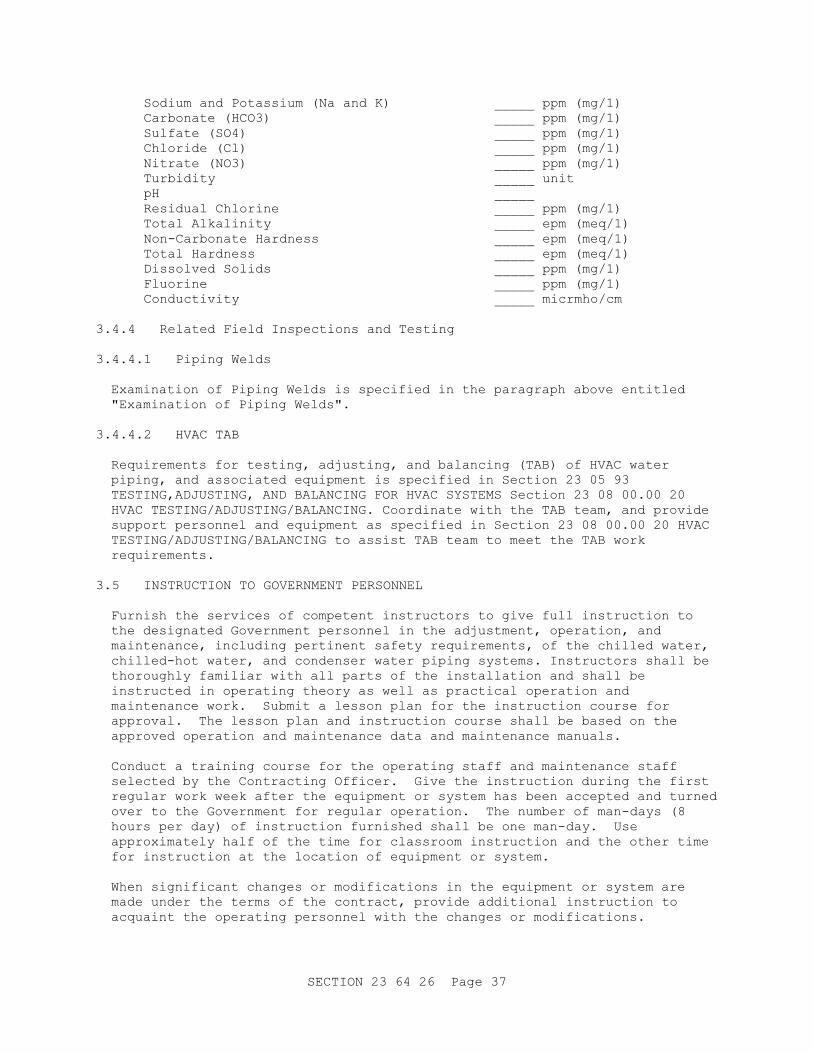
SECTION 23 64 26 Page 37
Sodium and Potassium (Na and K) _____ ppm (mg/1)Carbonate (HCO3) _____ ppm (mg/1)Sulfate (SO4) _____ ppm (mg/1)Chloride (Cl) _____ ppm (mg/1)Nitrate (NO3) _____ ppm (mg/1)Turbidity _____ unitpH _____Residual Chlorine _____ ppm (mg/1)Total Alkalinity _____ epm (meq/1)Non-Carbonate Hardness _____ epm (meq/1)Total Hardness _____ epm (meq/1)Dissolved Solids _____ ppm (mg/1)Fluorine _____ ppm (mg/1)Conductivity _____ micrmho/cm
3.4.4 Related Field Inspections and Testing
3.4.4.1 Piping Welds
Examination of Piping Welds is specified in the paragraph above entitled "Examination of Piping Welds".
3.4.4.2 HVAC TAB
Requirements for testing, adjusting, and balancing (TAB) of HVAC waterpiping, and associated equipment is specified in Section 23 05 93TESTING,ADJUSTING, AND BALANCING FOR HVAC SYSTEMS Section 23 08 00.00 20HVAC TESTING/ADJUSTING/BALANCING. Coordinate with the TAB team, and provide support personnel and equipment as specified in Section 23 08 00.00 20 HVACTESTING/ADJUSTING/BALANCING to assist TAB team to meet the TAB work requirements.
3.5 INSTRUCTION TO GOVERNMENT PERSONNEL
Furnish the services of competent instructors to give full instruction to the designated Government personnel in the adjustment, operation, and maintenance, including pertinent safety requirements, of the chilled water, chilled-hot water, and condenser water piping systems. Instructors shall be thoroughly familiar with all parts of the installation and shall be instructed in operating theory as well as practical operation and maintenance work. Submit a lesson plan for the instruction course forapproval. The lesson plan and instruction course shall be based on the approved operation and maintenance data and maintenance manuals.
Conduct a training course for the operating staff and maintenance staff selected by the Contracting Officer. Give the instruction during the first regular work week after the equipment or system has been accepted and turned over to the Government for regular operation. The number of man-days (8 hours per day) of instruction furnished shall be one man-day. Use approximately half of the time for classroom instruction and the other time for instruction at the location of equipment or system.
When significant changes or modifications in the equipment or system are made under the terms of the contract, provide additional instruction to acquaint the operating personnel with the changes or modifications.
SECTION 23 64 26 Page 38
3.6 ONE-YEAR INSPECTION REPORT FOR COOLING WATER
At the conclusion of the one year period, each connecting cooling tower and liquid chiller condenser inspect for problems due to corrosion, scale, and biological growth. If the equipment is found not to conform to the manufacturers recommended conditions, and the water treatment company recommendations have been followed; the water treatment company shall provide all chemicals and labor for cleaning or repairing the equipment as required by the manufacturer's recommendations.
-- End of Section --