Embed Size (px)
Citation preview

SEMATECHS2-93, S8-95
SEMI StandardS2-0703, S8-0701, F47-0200
®
HRZ Series
More effective energy-savingis achieved through use of aDC inverter compressor and an inverter pump.
Type of Fluorinated fluids/Ethylene glycol aqueous solution/ circulating fluid: Tap water, Deionized water
Temperature –20 to 40°C/20 to 90°C/–20 to 90°C range setting: Cooling 1 kW/2 kW/4 kW/8 kW/10 kW to Max.15 kW capacity: Temperature stability: ±0.1°C Refrigerant: R404A (HFC) /R134a (HFC)
Power consumption
1.1 kWh/h
Facility water
2 L/min
Inverter type
Circulating Fluid Temperature Controller Refrigerated Thermo-chiller
220
HR
SH
RS
090
HR
S100
/150
HR
SH
090
HR
SH
HR
SE
HR
ZH
RZ
DH
RW
HE
CR
HE
CH
ED
HE
BTe
chni
cal
Dat
a

Energy Saving
High Performance
HRZPower consumption:
Max.40% reduction (SMC comparison)In addition to the optimum control of the expansion valve by the original controller, by recycling the heat emitted from the facility water, power consumption is dramatically reduced.
Currentmodel
HRZ002-L 3.9 kWh/h
6.2 kWh/h
Operating conditions: –10°C, 0 kW with 50% load, 2 kW with 50% load
Reduced running cost Contribution to the environmental preservation
Circulating fluid:
Max.40% reduction (SMC comparison)Enhanced temperature control technology and the dual tank construction achieved the reduced circulating fluid required for operation.
Reduced initial cost Contribution to the environmental preservation
Currentmodel
HRZ002-H 12 L
20 L
Comparison of the required circulating fluid inside a Thermo-chiller
More effective energy-saving is achieved through use of a DC inverter compressor and an inverter pump.
Power consumption:
Max.82% reduction (SMC comparison)
Current model
Heated refrigerantemission gas
Cold refrigerant liquid
Cold refrigerant liquid
Heater
Circulating fluid Circulating fluid∗ This illustration is for an image only. For piping systems, refer to “Construction and Principles” on page 225.
Facility water:
Max.75% reduction (SMC comparison)Enhanced performance of a heat exchanger, recycle use of the emitted heat and the reduced power consumption achieved the reduced facility water amount.
Reduced facilities investment Space saved facility water equipment Reduced running cost
Currentmodel
HRZ002-L 5 L/min
20 L/min
Operating conditions: –10°C, 0 kW with 50% load, 2 kW with 50% load
Facility water:
Max.90% reduction (SMC comparison)
Currentmodel
HRZ010-WS 2 L/min
20 L/min
Operating conditions: –10°C, 0 kW with 50% load, 2 kW with 50% loadOperating conditions: –10°C, 0 kW with 50% load, 2 kW with 50% load
Currentmodel
HRZ010-WS
6.2 kWh/h
1.1 kWh/h
Cooling time: Max.43% reduction (SMC comparison)Special temperature control technology achieved the utmost performance, resulting in the reduced cooling time.
-19.0
-20.0
-21.0
-19.0
-20.0
-21.0
HRZ004-L
2 kW load
0 kW load
15 sec. Time
Circ
ulat
ing
fluid
tem
pera
ture
[°C
]
Circ
ulat
ing
fluid
tem
pera
ture
[°C
]
0
Current model
HRZ004-L
40
-20
120 sec.
Time43% reduction
Temperature stability: ±0.1°C(When a load is stable)Enhanced temperature control technology achieved ±0.1°C temperature stabilities when a load is stable.
Current model
221

40353025201510
Circulating fluid temperature setting [°C]
50-5-10-15-200
2
4
6
8
10
12
14
1615
Coo
ling
capa
city
[kW
]
HRZ008-L
PumpHeat exchanger
400 mm100 mm
380 mm845 mm
870 mm
Space Saving
Installation area:
Max.29% reduction (SMC comparison)By emitting the heat from the rear side, ventilation slits on the side are unnecessary offering reduced installation space.
Current model: Body space: W400 mm x D845 mm Ventilation space: 100 mm
HRZ008-H: Body space: W380 mm x D870 mm Ventilation space: 0
0.93 m20.66 m2HRZ008-H Current model
Leakless
All in tank Housing the pump or heat exchanger inside the tank has eliminated any external leakage of the circulating fluid.
Communications Contact input/output signal
Serial RS-485 communication
Analog communication (Refer to “Options” on page 249.)
DeviceNet communication (Refer to “Options” on page 249.)
Cooling capacity: Max.15 kWUp to 15 kW cooling capacity achieved.
Fluid contact parts adopt the materials compatible for various circulating fluids.(Stainless steel, EPDM, etc.)
• Fluorinated fluids: Flourinert™ FC-3283, FC-40
GALDEN® HT135, HT200• 60% ethylene glycol aqueous solution• Deionized water/Tap waterRegarding the fluid other than the above, please contact SMC. Flourinert™ is a trademark of 3M. GALDEN® is a registered trademark of Solvay Solexis, Inc.
TrademarkDeviceNet™ is a trademark of ODVA.
222
HR
SH
RS
090
HR
S100
/150
HR
SH
090
HR
SH
HR
SE
HR
ZH
RZ
DH
RW
HE
CR
HE
CH
ED
HE
BTe
chni
cal
Dat
a

HRZ
Easy Maintenance
Circulating fluid automatic recovery function (Refer to “Options” on page 249.)
Circulating fluid inside a thermo-chiller tank can be recovered automatically. (Recovery volume: 15 L to 17 L)
Reduced maintenance time Faster operation Reduced circulating liquid loss by evaporation or spill
Current model
Normal operation Fluid returns to the main tank from the circulating fluid recovery tank.
Circulating fluidrecovery
1 2 3
Option
User’sequipment
Internalpump
Circulatingpump
Heatexchanger
Maintank
N2 purge port
Option
N2
User’sequipment
Internalpump
Circulatingpump
Heatexchanger
Maintank
N2 purge port
Option
User’sequipment
Internalpump
Circulatingpump
Heatexchanger
Maintank
N2 purge port
Circulating fluid electric resistance ratio control function (Refer to “Options” on page 249.)
(DI control kit)
Easy maintenance Checking the electrical component parts accessible from the front side only
Possible to replace the maintenance parts (such as a pump) without removing the pipings and discharging the circulating fluid.
Various alarm displays (Refer to page 245.)
All you have to do is to
push the communication
button for recovery
and reset! All you have to do is to
push the communication
button for recovery
and reset!
223
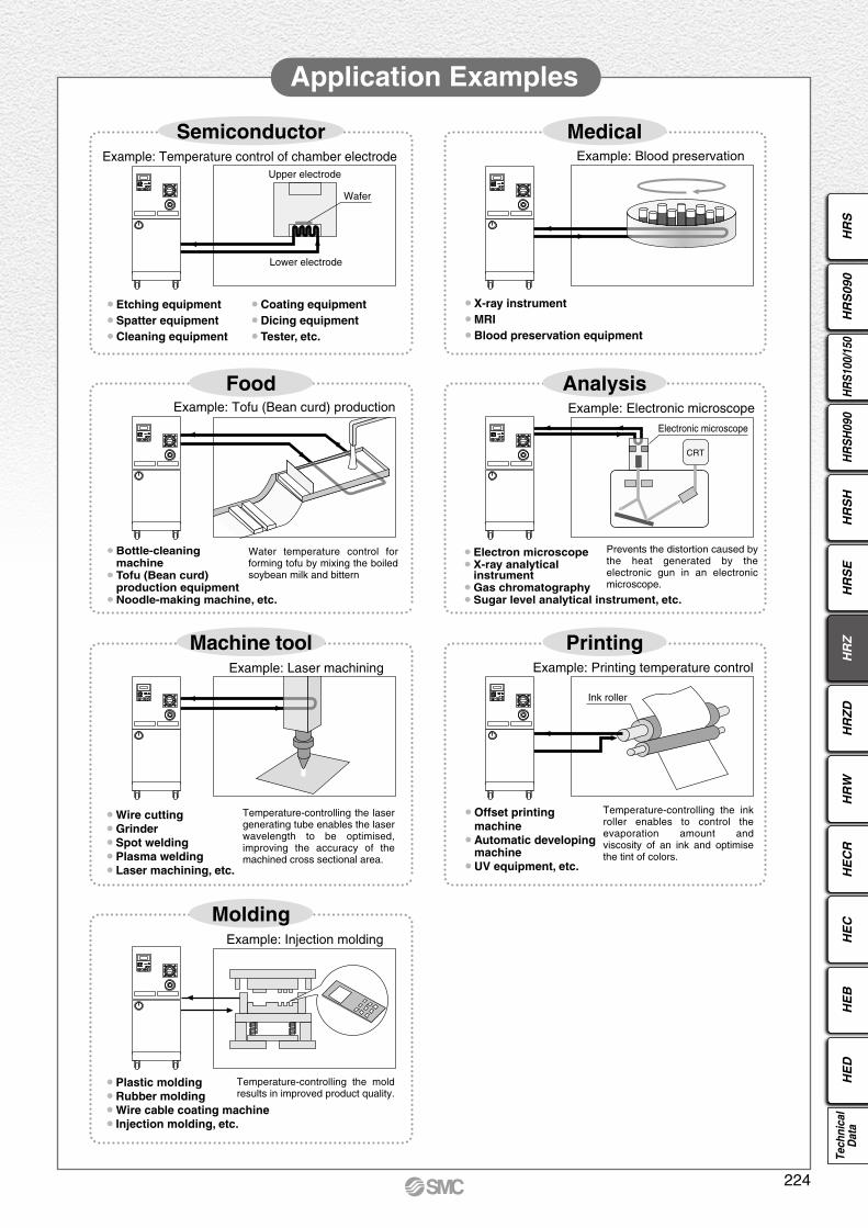
Application Examples
SemiconductorExample: Temperature control of chamber electrode
Upper electrode
Wafer
Lower electrode
• Etching equipment
• Spatter equipment
• Cleaning equipment
• Coating equipment
• Dicing equipment
• Tester, etc.
MedicalExample: Blood preservation
• X-ray instrument
• MRI
• Blood preservation equipment
FoodExample: Tofu (Bean curd) production
• Bottle-cleaning machine• Tofu (Bean curd) production equipment• Noodle-making machine, etc.
Water temperature control for forming tofu by mixing the boiled soybean milk and bittern
Analysis
CRT
Example: Electronic microscope
Electronic microscope
Prevents the distortion caused by the heat generated by the electronic gun in an electronic microscope.
• Electron microscope• X-ray analytical instrument• Gas chromatography• Sugar level analytical instrument, etc.
Machine toolExample: Laser machining
• Wire cutting• Grinder • Spot welding• Plasma welding• Laser machining, etc.
Temperature-controlling the laser generating tube enables the laser wavelength to be optimised, improving the accuracy of the machined cross sectional area.
PrintingExample: Printing temperature control
Ink roller
• Offset printing machine• Automatic developing machine• UV equipment, etc.
Temperature-controlling the ink roller enables to control the evaporation amount and viscosity of an ink and optimise the tint of colors.
MoldingExample: Injection molding
• Plastic molding• Rubber molding• Wire cable coating machine• Injection molding, etc.
Temperature-controlling the mold results in improved product quality.
224
HR
SH
RS
090
HR
S100
/150
HR
SH
090
HR
SH
HR
SE
HR
ZH
RZ
DH
RW
HE
CR
HE
CH
ED
HE
BTe
chni
cal
Dat
a

Circulating fluid circuitWith the circulating pump, circulating fluid will be discharged to the user’s equipment side. After the circulating fluid will heat or cool the user’s equipment side, it will be returned to the main tank via the heat exchanger.A sub-tank is not used under the normal operation. It will be used when a circulating fluid is recovered from the user’s equipment side.The internal pump is used to transfer a circulating fluid from the sub-tank to the main tank. (Refer to “Circulating fluid automatic recovery function” on page 223.)
Refrigeration circuitWhen the circulating fluid temperature is rising higher than the set temperature, open the expansion valve (a) to introduce refrigerant gas at a lower temperature to the heat exchanger. With this, the circulating fluid will be cooled down.Oppositely, when the circulating fluid is getting lower against the set temperature, open the expansion valve (b) and introduce refrigerant gas at a high temperature without going through the water-cooled condenser to the heat exchanger. With this heat, the circulating fluid will be heated.
Construction and Principles
Refrigeration circuit
Facility water circuit
Injection valve
Expansion valve (a)
Expansion valve (b)
Compressor
Water-regulating valve
Facilitywateroutlet
Water-cooled condenser
Facilitywaterinlet
Refrigerantdryer
High- pressuregauge
High-pressure shutoffpressure switch
Flow rate sensor
Circulating fluid circuit
Internalpump
Circulatingpump
Levelswitch
Levelswitch
Heatexchanger
Maintank
Temperaturesensor
Pressuresensor
Circulatingfluid outlet
Circulatingfluid returninlet
Sub-tank
225

C O N T E N T SHRZ Series
Model SelectionGuide to Model Selection.................................. Page 227
Required Cooling Capacity Calculation ............ Page 228
Precautions on Model Selection ....................... Page 229
Circulating Fluid Typical Physical Property Values ... Page 230
Fluorinated Fluid TypeHow to Order/Specifications ............................. Page 231
Cooling Capacity/Heating Capacity .................. Page 232
Pump Capacity ................................................. Page 233
Ethylene Glycol TypeHow to Order/Specifications ............................. Page 234
Cooling Capacity/Heating Capacity .................. Page 235
Pump Capacity ................................................. Page 236
Tap/Deionized Water TypeHow to Order/Specifications ............................. Page 237
Cooling Capacity/Heating Capacity/Pump Capacity ... Page 238
Double Inverter TypeHow to Order/Specifications ............................. Page 239
Cooling Capacity/Heating Capacity/Pump Capacity ... Page 240
Common SpecificationsDimensions ....................................................... Page 241
Communication Functions ................................ Page 243
· Contact Input/Output...................................... Page 243
· Serial RS-485 ................................................ Page 244
· Connector Location........................................ Page 244
Operation Display Panel ................................... Page 245
Alarm ................................................................ Page 245
Optional AccessoriesqBypass Piping Set ........................................ Page 246
wAnti-quake Bracket ....................................... Page 246
e4-Port Manifold ............................................. Page 247
rDI Filter ......................................................... Page 247
t Insulating Material for DI Filter ...................... Page 247
y60% Ethylene Glycol Aqueous Solution ....... Page 248
uConcentration Meter ..................................... Page 248
OptionsAnalog Communication ..................................... Page 249
DeviceNet Communication ............................... Page 249
NPT Fitting ........................................................ Page 249
DI Control Kit .................................................... Page 249
Circulating Fluid Automatic Recovery ............... Page 250
Specific Product Precautions ................................. Page 251
Refrigerated Thermo-chiller HRZ Series
226
HR
SH
RS
090
HR
S100
/150
HR
SH
090
HR
SH
HR
SE
HR
ZH
RZ
DH
RW
HE
CR
HE
CH
ED
HE
BTe
chni
cal
Dat
a

HRZ Series
Model Selection
HRZ004-H
HRZ008-H
HRZ002-H
HRZ001-H
Guide to Model Selection
1. How much is the temperature in degrees centigrade for the circulating fluid?
Temperature range which can be set with the thermo-chillerL : –20°C to 40°C (“L2” (tap water, deionized water specification) can be set 10°C to 40°C.) H : 20°C to 90°C W : –20°C to 90°C (Select “W” only when the temperature ranges of “L” or “H” are not applicable. HRZ010-W2S (tap water, deionized water specification) can be set 10°C to 60°C.)
Example) User requirement: 50°C ( Temperature range 20°C to 90°C, “H” type will be appropriate.)
2. What kind of the circulating fluids will be used?
Relationship between circulating fluid (which can be used with the thermo-chiller) and temperature
–20°C 10°C 20°C 40°C 60°C 90°C
Fluorinated fluids: Fluorinert™ FC-3283/GALDEN® HT135
Fluorinated fluids: Fluorinert™ FC-40/GALDEN® HT200
60% ethylene glycol aqueous solution
Tap water/Deionized water
Example) User requirement: Fluorinated fluids
Based on the results 1. and 2., Cooling capacity relating “Fluorinated fluids” and “Temperature range 20°C to 90°C” is shown on page 232.
[Cooling Capacity Graph] Circulating Fluid: Fluorinated Fluids, Temperature Range: 20 to 90°C
3. What is the kW for the required cooling capacity? ∗ To calculate the cooling capacity, referring to page 228.
Example) User requirement: 5 kW Plot the point of intersection between the operating temperature (50°C) and the cooling capacity (5 kW) in the cooling capacity graph.
Circulating fluid temperature setting [°C]
Coo
ling
capa
city
[kW
]
10
9
8
7
6
4
3
2
1
020 30 40 50 60 70 80 90
5
User requirement
The point plotted in the graph is the requirement from the user. Select the thermo-chiller models exceeding this point. In this case, select the HRZ004-H.
Fluorinert™ is a trademark of 3M. GALDEN® is a registered trademark of Solvay Solexis, Inc.
227

Model Selection HRZ Series
Required Cooling Capacity Calculation
Example 1: When the heat generation amount in the user’s equipment is known.
Cooling capacity = Considering a safety factor of 20%, 3.5 x 1.2 = 4.2 kW
Heat generation amount Q: 3.5 kW
Example 2: When the heat generation amount in the user’s equipment is not known.
: Unknown
: 6.0°C (6.0 K)
: 20°C (293.15 K)
: 26°C (299.15 K)
: 20 L/min
: Fluorinated fluid
Density : 1.80 x 10³ kg/m3
Specific heat C: 0.96 x 10³ J/(kg·K)(at 20°C)
Obtain the temperature difference between inlet and outlet by circulating the circulating fluid inside the user’s equipment.
Heat generation amount Q
Circulating fluid temperature difference T (= T2 – T1)
Circulating fluid outlet temperature T1
Circulating fluid return temperature T2
Circulating fluid flow rate L
Circulating fluid
∗ Refer to page 230 for the typical physical property valuesby circulating fluid.
Q =T x L x x C
60 x 1000
6.0 x 20 x 1.80 x 103 x 0.96 x 103
60 x 1000
= 3456 W = 3.5 kW
=
Cooling capacity = Considering a safety factor of 20%,
3.5 x 1.2 = 4.2 kW
L
Thermo-chiller
T2: Return temperature
T = T2 – T1
T1: Outlet temperature
User’sequipment
Unknown
6.0°C20°C26°C1.2 m3/h
Fluorinated fluid
Density : 1.80 x 10³ kg/m3
Specific heat C: 0.23 kcal/kg·°C(at 20°C)
∗ Refer to page 230 for the typical physical property values by circulating fluid.
Example of current measurement units (Reference)
Cooling capacity = Considering a safety factor of 20%,
3.5 x 1.2 = 4.2 kW
Q =T x L x x C
860
6.0 x 1.2 x 1.80 x 103 x 0.23860
= 3.5 kW
=
228
HR
SH
RS
090
HR
S100
/150
HR
SH
090
HR
SH
HR
SE
HR
ZH
RZ
DH
RW
HE
CR
HE
CH
ED
HE
BTe
chni
cal
Dat
a

Required Cooling Capacity Calculation
Cooled substance total volume V
Cooling time h
Cooling temperature difference T
Circulating fluid
∗ Refer to page 230 for the typical physical property valuesby circulating fluid.
Cooling capacity = Considering a safety factor of 20%,
2.3 x 1.2 =
T x V x x Ch x 60 x 1000
20 x 60 x 1.80 x 103 x 0.96 x 103
15 x 60 x 1000
(In this case, selected thermo-chiller model will be either HRZ002-L or HRZ004-H.)
0.06 m3
0.25 h
20°CFluorinated fluid
Density : 1.80 x 10³ kg/m3
Specific heat C: 0.23 kcal/kg·°C(at 20°C)
∗ Refer to page 230 for the typical physical property valuesby circulating fluid.
Example of current measurement units (Reference): 60 L
: 15 min
: 20°C (20 K)
(40°C – 20°C → 20°C)
: Fluorinated fluid
Density : 1.80 x 10³ kg/m3
Specific heat C: 0.96 x 10³ J/(kg·K)(at 20°C)
Example 3. When there is no heat generation, and when cooling the object below a certain temperature and period of time.
Q =
= 2304 W = 2.3 kW
=
2.8 kW (When the circulating fluid temperature is 20°C.)
Q =T x V x x C
h x 860
=20 x 0.06 x 1.80 x 103 x 0.23
0.25 x 860
= 2.3 kW
Cooling capacity = Considering a safety factor of 20%,
2.3 x 1.2 =
(In this case, selected thermo-chiller model will be either HRZ002-L or HRZ004-H.)
2.8 kW (When the circulating fluid temperature is 20°C.)
∗ This is the calculated value by changing the fluid temperature only. Thus, it varies substantially depending on the water bath or piping material or shape.
Thermo-chiller
Water bath
V20°C
After 15 min, cool 40°C down to 20°C.
1. Heating capacity When setting the circulating fluid temperature at a higher temperature than the room temperature, the circulating fluid temperature will be heated with the thermo-chiller. Heating capacity varies depending on the model of the HRZ series. Also, the heating capacity varies depending on the circulating fluid temperature. Consider the heat radiation amount or thermal capacity of the user’s equipment. Check beforehand if the required heating capacity is provided, based on the heating capacity graph for the respective model.
2. Pump capacity <Circulating fluid flow rate> Pump capacity varies depending on the model selected from the HRZ series. Also, circulating fluid flow varies depending on the circulating fluid discharge pressure. Consider the installation height difference between our thermo-chiller and a user’s equipment, and the piping resistance such as circulating fluid pipings, or piping size, or piping curves in the machine. Check beforehand if the required flow is achieved using the pump capacity curves for each respective model.
<Circulating fluid discharge pressure>Circulating fluid discharge pressure has the possibility to increase up to the maximum pressure in the pump capacity curves for the respective model. Check beforehand if the circulating fluid pipings or circulating fluid circuit of the user’s equipment are fully durable against this pressure.
Precautions on Model Selection
HRZ Series
229

Model Selection HRZ Series
Circulating Fluid Typical Physical Property Values∗ Shown below are reference values. Please contact circulating fluid supplier for details.
Fluorinated FluidsPhysical property
valueTemperature
–10°C
20°C
50°C
80°C
Density
[kg/m3] [g/L]
Specific heat C
[J/(kg·K)]
0.87 x 10³
0.96 x 10³
1.05 x 10³
1.14 x 10³
([kcal/kg·°C])
(0.21)
(0.23)
(0.25)
(0.27)
1.87 x 10³
1.80 x 10³
1.74 x 10³
1.67 x 10³
Water
Density : 1 x 10³ [kg/m3] [g/L] Specific heat C: 4.2 x 10³ [J/(kg·K)] (1.0 [kcal/kg·°C])
60% Ethylene Glycol Aqueous SolutionPhysical property
valueTemperature
–10°C
20°C
50°C
80°C
Density
[kg/m3] [g/L]
Specific heat C
[J/(kg·K)]
3.02 x 10³
3.15 x 10³
3.27 x 10³
3.40 x 10³
([kcal/kg·°C])
(0.72)
(0.75)
(0.78)
(0.81)
1.10 x 10³
1.08 x 10³
1.06 x 10³
1.04 x 10³
230
HR
SH
RS
090
HR
S100
/150
HR
SH
090
HR
SH
HR
SE
HR
ZH
RZ
DH
RW
HE
CR
HE
CH
ED
HE
BTe
chni
cal
Dat
a

Thermo-chillerHRZ Series
®
SEMI
Specifications (For details, please refer to our “Product Specifications” information.)
How to Order
001 LHRZFluorinated Fluid Type
Cooling capacitySymbol
001002004008
Cooling capacity1 kW2 kW4 kW8 kW
Temperaturerange setting 1 kW 2 kW 4 kW 8 kWSymbol
–20 to 40°C 20 to 90°C–20 to 90°C
—
—
LHW
Temperature range setting
NoneAnalog communicationDeviceNet communicationNPT fittingSI unit onlyCirculating fluid automatic recovery
NilCDN
W∗1
Z
Option (Refer to pages 249 and 250.)
∗1 It should have no condensation.∗2 Fluorinert™ is a trademark of 3M and GALDEN® is a registered trademark of Solvay Solexis, Inc. Regarding the fluid other than the above, please contact SMC.∗3 q Facility water temperature: 25°C, w Circulating fluid flow rate: Values at rated circulating fluid flow rate. Values common for 50/60 Hz.∗4 Value with a stable load without turbulence in the operating conditions. It may be out of this range depending on operating conditions.∗5 The capacity at the thermo-chiller outlet when the circulating fluid temperature is 20°C.∗6 Required flow rate for cooling capacity or maintaining the temperature stability. When used below the rated flow, use the individually sold, “Bypass Piping Set” (Refer to page 246).∗7 Minimum volume required for operating only the thermo-chiller. (Circulating fluid temperature: 20°C, including the thermo-chiller’s internal pipings or heat exchanger)∗8 Preliminary space volume without main tank capacity. Available for collecting the circulating fluid inside an external piping or for preliminary injection.∗9 Required flow rate when a load for the cooling capacity is applied at a facility water temperature of 25°C. ∗10 Weight in the dry state without circulating fluids
Model HRZ001-LCooling methodRefrigerantRefrigerant charge kgControl systemAmbient temp./humidity∗1
Circulating fluid∗2
Temp. range setting∗1 °C
Cooling capacity∗3 kW
Heating capacity∗3 kW
Temp. stability∗4 °C
Rated flow∗6 L/minMain tank capacity∗7 L Sub-tank capacity∗8 L Port sizeFluid contact material Temperature range °CPressure range MPaRequired flow rate (50/60 Hz)∗9 L/minPort sizeFluid contact materialPower supplyBreaker capacity A Rated current A AlarmCommunications
Pump capacity (50/60 Hz)∗5
MPa
Weight∗10 kgSafety standards
HRZ002-L HRZ004-L HRZ008-L HRZ001-H HRZ002-H HRZ004-H HRZ008-H HRZ002-W HRZ008-WWater-cooled refrigeration
R404A (HFC)
PID controlTemperature: 10 to 35°C, Humidity: 30 to 70%RH
20Approx. 15Approx. 16
30Approx. 22Approx. 17
20Approx. 12Approx. 15
Rc3/4Stainless steel, EPDM, Copper brazing (Heat exchanger), PPS, Silicone, Fluororesin
10 to 250.3 to 0.7
Rc1/2Stainless steel, EPDM, Copper brazing (Heat exchanger), Silicone, Brass, NBR
3-phase 200 VAC 50 Hz, 3-phase 200 to 208 VAC 60 Hz Allowable voltage range ±10%
Refer to page 245.Contact input/output (D-sub 25 pin) and Serial RS-485 (D-sub 9 pin) (Refer to pages 243 and 244.)
UL, CE marking, SEMI (S2-0703, S8-0701, F47-0200), SEMATECH (S2-93, S8-95)
3020 25
6046
165 175 275 145 165
2014
3023
5/5 6/6 15/22 18/23 3/4 5/6 9/10 13/14 6/7 13/14
Approx. 15Approx. 16
±0.1
–20 to 40 20 to 90 –20 to 901.0
(at –10°C)
0.45/0.65 (at 20 L/min) 0.45/0.65 (at 20 L/min)0.65/0.95(at 30 L/min)
0.40/0.60(at 20 L/min)
Fluorinert™ FC-3283/GALDEN® HT135 Fluorinert™ FC-40/GALDEN® HT200
• –20 to 40°C: Fluorinert™
FC-3283/GALDEN® HT135• 20 to 90°C: Fluorinert™ FC-40/GALDEN® HT200
2.0(at –10°C)
1.0(at 20°C)
2.0(at 20°C)
4.0(at 20°C)
8.0(at 20°C)
2.0(at 20°C)
8.0(at 20°C)
4.0(at –10°C)
8.0(at –10°C)
2.8(at –10°C)
3.2(at –10°C)
2.3(at 20°C)
2.6(at 20°C)
2.8(at 20°C)
3.0(at 20°C)
2.3(at 20°C)
3.3(at 20°C)
3.6(at –10°C)
5.9(at –10°C)
Cir
cula
tin
g f
luid
sys
tem
Cooli
ng w
ater s
ystem
Elec
trica
l sys
tem
1.15 1.15 1.3 2 0.75 0.75 1.15 1.15 1.15 1.15
Fluorinated Fluid Type
∗1 Unit selection function is not available in Japan due to new measurement law. If using this product within Japan, please select this option.Fixed unit: MPa/°C
231B

Thermo-chiller HRZ Series
HRZ001-L/002-L/004-L/008-L
HRZ002-W/008-W
HRZ001-H/002-H/004-H/008-H
HRZ001-L/002-L/004-L/008-L HRZ001-H/002-H/004-H/008-H
HRZ002-W/008-W
0
2
4
6
8
10
12
14
16
–20 –10 0 10 20 30 40
Circulating fluid temperature [°C]
Coo
ling
capa
city
[kW
]
HRZ001-L
HRZ002-L
HRZ004-L
HRZ008-L
0
1
2
3
4
5
6
7
8
9
10
20 30 40 50 60 70 80 90
Circulating fluid temperature [°C]
Coo
ling
capa
city
[kW
] HRZ008-H
HRZ004-H
HRZ002-H
HRZ001-H
0
1
2
3
4
5
6
7
8
9
–20 –10 0 10 20 30 40 50 60 70 80 90
Circulating fluid temperature [°C]
Coo
ling
capa
city
[kW
]
HRZ008-W
HRZ002-W
Circulating fluid temperature [°C]
Hea
ting
capa
city
[kW
]
0
1
2
3
4
–20 –10 0 10 20 30 40 50 60 70 80 90
HRZ008-W
HRZ002-W
Circulating fluid temperature [°C]
Hea
ting
capa
city
[kW
]
0
1
2
3
4
5
6
7
–20 –10 0 10 20 30 40
HRZ008-L
HRZ004-L
HRZ002-L
HRZ001-L
Circulating fluid temperature [°C]
Hea
ting
capa
city
[kW
]
0
1
2
3
4
20 30 40 50 60 70 80
HRZ008-HHRZ004-H
HRZ002-H
HRZ001-H
90
Cooling Capacity
Heating Capacity
232
HR
SH
RS
090
HR
S100
/150
HR
SH
090
HR
SH
HR
SE
HR
ZH
RZ
DH
RW
HE
CR
HE
CH
ED
HE
BTe
chni
cal
Dat
a

HRZ Series
HRZ001-H/002-HHRZ004-H/008-HHRZ002-W/008-W
Pump Capacity (Thermo-chiller Outlet)
HRZ001-L/002-L/004-L
0 10 20 30 40
0.9
0.8
0.7
0.6
0.5
0.4
0.3
0.2
0.1
0
50
40
30
20
10
0
HRZ008-L
0 10 20 30 40
1.21.11.00.90.80.70.60.50.40.30.20.10
70
60
50
40
30
20
10
0
0 10 20 30 40
0.8
0.7
0.6
0.5
0.4
0.3
0.2
0.1
0
40
30
20
10
00 10 20 30 40
0.9
0.8
0.7
0.6
0.5
0.4
0.3
0.2
0.1
0
50
40
30
20
10
0
[Outlet: 60 Hz]
[Outlet: 50 Hz]
[Return port]
Circulating fluid flow rate [L/min]Lifting height
[m]Pressure[MPa]
[Outlet: 60 Hz]
[Outlet: 50 Hz]
[Return port]
Circulating fluid flow rate [L/min]Lifting height
[m]Pressure[MPa]
[Outlet: 60 Hz]
[Outlet: 50 Hz]
[Return port]
Circulating fluid flow rate [L/min]Lifting height
[m]Pressure[MPa]
[Outlet: 60 Hz]
[Outlet: 50 Hz]
[Return port]
Circulating fluid flow rate [L/min]Lifting height
[m]Pressure[MPa]
∗ When the circulating fluid flow is below 6 L/min, the in-built operation stop alarm will be activated.It is not possible to run the equipment. (common for all models)
233
®
SEMI
Thermo-chillerHRZ Series
Specifications (For details, please refer to our “Product Specifications” information.)
How to Order
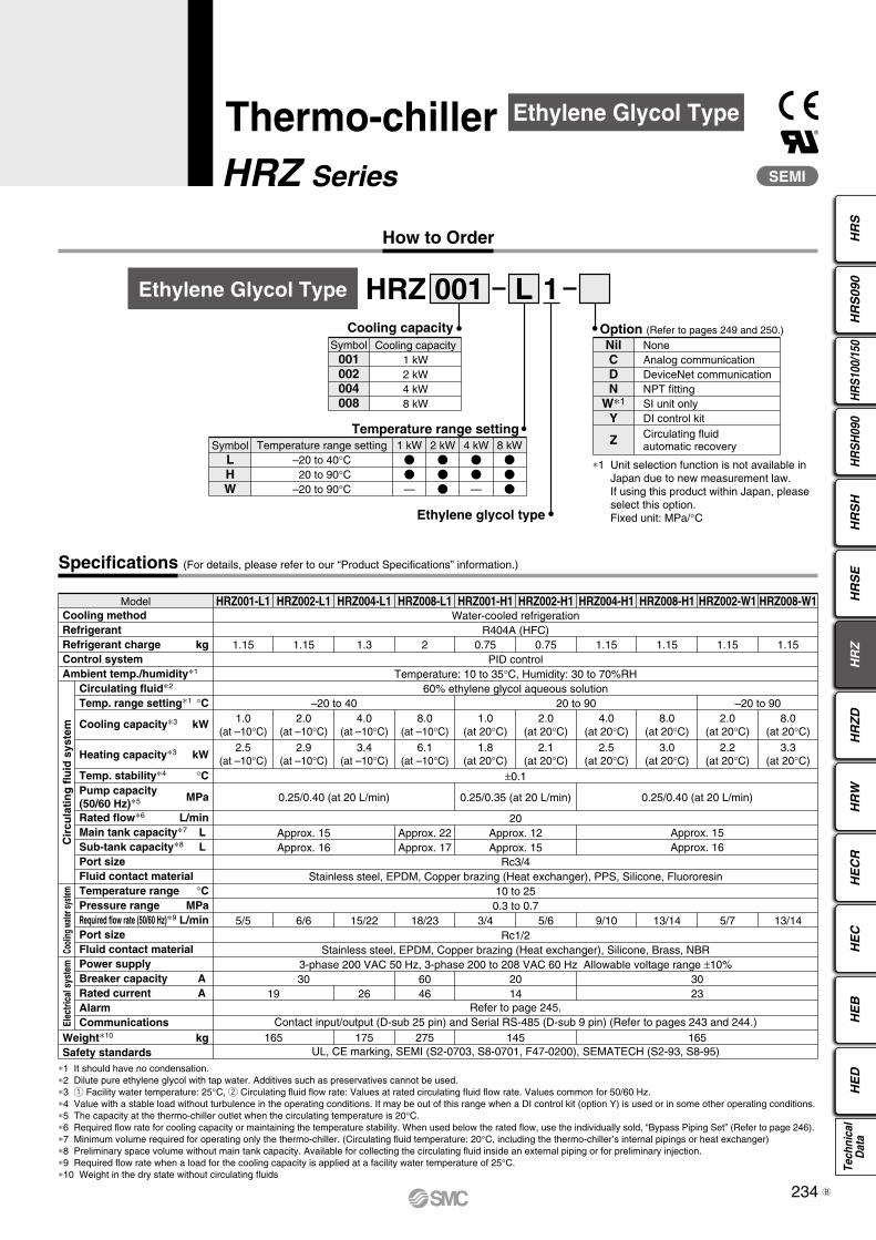
001 L 1HRZEthylene Glycol Type
Symbol001002004008
Cooling capacity1 kW2 kW4 kW8 kW
Cooling capacity
Temperature range setting–20 to 40°C 20 to 90°C–20 to 90°C
1 kW—
2 kW
4 kW—
8 kW
SymbolLHW
Temperature range setting
NoneAnalog communicationDeviceNet communicationNPT fittingSI unit onlyDI control kitCirculating fluidautomatic recovery
NilCDN
W∗1
Y
Z
Option (Refer to pages 249 and 250.)
Ethylene glycol type
∗1 It should have no condensation.∗2 Dilute pure ethylene glycol with tap water. Additives such as preservatives cannot be used.∗3 q Facility water temperature: 25°C, w Circulating fluid flow rate: Values at rated circulating fluid flow rate. Values common for 50/60 Hz.∗4 Value with a stable load without turbulence in the operating conditions. It may be out of this range when a DI control kit (option Y) is used or in some other operating conditions. ∗5 The capacity at the thermo-chiller outlet when the circulating temperature is 20°C.∗6 Required flow rate for cooling capacity or maintaining the temperature stability. When used below the rated flow, use the individually sold, “Bypass Piping Set” (Refer to page 246).∗7 Minimum volume required for operating only the thermo-chiller. (Circulating fluid temperature: 20°C, including the thermo-chiller’s internal pipings or heat exchanger)∗8 Preliminary space volume without main tank capacity. Available for collecting the circulating fluid inside an external piping or for preliminary injection.∗9 Required flow rate when a load for the cooling capacity is applied at a facility water temperature of 25°C. ∗10 Weight in the dry state without circulating fluids
Cooling methodRefrigerantRefrigerant charge kgControl systemAmbient temp./humidity∗1
Weight∗10 kgSafety standards
Circulating fluid∗2
Temp. range setting∗1 °C
Temp. stability∗4 °C
Cooling capacity∗3 kW
Heating capacity∗3 kW
Rated flow∗6 L/minMain tank capacity∗7 L Sub-tank capacity∗8 L Port sizeFluid contact material Temperature range °CPressure range MPaRequired flow rate (50/60 Hz)∗9 L/minPort sizeFluid contact materialPower supplyBreaker capacity A Rated current A AlarmCommunications
Water-cooled refrigerationR404A (HFC)
PID controlTemperature: 10 to 35°C, Humidity: 30 to 70%RH
60% ethylene glycol aqueous solution
±0.1
0.25/0.40 (at 20 L/min)
Approx. 15Approx. 16
5/5
3019
165 175 275 145 165
266046
2014
Refer to page 245.Contact input/output (D-sub 25 pin) and Serial RS-485 (D-sub 9 pin) (Refer to pages 243 and 244.)
UL, CE marking, SEMI (S2-0703, S8-0701, F47-0200), SEMATECH (S2-93, S8-95)
3023
6/6 15/22 18/23 3/4 5/6 9/10 13/14 5/7 13/14
Approx. 22Approx. 17
20Approx. 12Approx. 15
Rc3/4Stainless steel, EPDM, Copper brazing (Heat exchanger), PPS, Silicone, Fluororesin
10 to 250.3 to 0.7
Rc1/2Stainless steel, EPDM, Copper brazing (Heat exchanger), Silicone, Brass, NBR
3-phase 200 VAC 50 Hz, 3-phase 200 to 208 VAC 60 Hz Allowable voltage range ±10%
Approx. 15Approx. 16
0.25/0.35 (at 20 L/min) 0.25/0.40 (at 20 L/min)
–20 to 40 20 to 90 –20 to 901.0
(at –10°C)2.0
(at –10°C)1.0
(at 20°C)2.0
(at 20°C)4.0
(at 20°C)8.0
(at 20°C)2.0
(at 20°C)8.0
(at 20°C)
Model HRZ001-L1 HRZ002-L1 HRZ004-L1 HRZ008-L1 HRZ001-H1 HRZ002-H1 HRZ004-H1 HRZ008-H1 HRZ002-W1 HRZ008-W1
4.0(at –10°C)
8.0(at –10°C)
2.5(at –10°C)
2.9(at –10°C)
1.8(at 20°C)
2.1(at 20°C)
2.5(at 20°C)
3.0(at 20°C)
2.2(at 20°C)
3.3(at 20°C)
3.4(at –10°C)
6.1(at –10°C)
Pump capacity (50/60 Hz)∗5
MPa
Cir
cula
tin
g f
luid
sys
tem
Cooli
ng w
ater s
ystem
Elec
trica
l sys
tem
1.15 1.15 1.3 2 0.75 0.75 1.15 1.15 1.15 1.15
Ethylene Glycol Type
∗1 Unit selection function is not available in Japan due to new measurement law. If using this product within Japan, please select this option.Fixed unit: MPa/°C
234
HR
SH
RS
090
HR
S100
/150
HR
SH
090
HR
SH
HR
SE
HR
ZH
RZ
DH
RW
HE
CR
HE
CH
ED
HE
BTe
chni
cal
Dat
a
B

HRZ Series
HRZ002-W1/008-W1
HRZ001-H1/002-H1/004-H1/008-H1
HRZ001-L1/002-L1/004-L1/008-L1 HRZ001-H1/002-H1/004-H1/008-H1
HRZ002-W1/008-W1
HRZ001-L1/002-L1/004-L1/008-L1
0
2
4
6
8
10
12
14
16
–20 –10 0 10 20 30 40
Circulating fluid temperature [°C]
Coo
ling
capa
city
[kW
]
HRZ001-L1
HRZ002-L1
HRZ004-L1
HRZ008-L1
0
1
2
3
4
5
6
7
8
9
10
20 30 40 50 60 70 80 90
Circulating fluid temperature [°C]
Coo
ling
capa
city
[kW
] HRZ008-H1
HRZ004-H1
HRZ002-H1
HRZ001-H1
0
1
2
3
4
5
6
7
8
9
–20 –10 0 10 20 30 40 50 60 70 80 90
Circulating fluid temperature [°C]
Coo
ling
capa
city
[kW
]
HRZ008-W1
HRZ002-W1
Circulating fluid temperature [°C]
Hea
ting
capa
city
[kW
]
0
1
2
3
4
5
–20 –10 0 10 20 30 40 50 60 70 80 90
HRZ008-W1
HRZ002-W1
Circulating fluid temperature [°C]
Hea
ting
capa
city
[kW
]
0
1
2
3
4
5
6
7
–20 –10 0 10 20 30 40
HRZ008-L1
HRZ004-L1
HRZ002-L1
HRZ001-L1
Circulating fluid temperature [°C]
Hea
ting
capa
city
[kW
]
0
1
2
3
4
20 30 40 50 60 70 80 90
HRZ008-H1
HRZ004-H1
HRZ002-H1
HRZ001-H1
Cooling Capacity
Heating Capacity
235

Thermo-chiller HRZ Series
HRZ001-H1/002-H1
HRZ008-L1
HRZ001-L1/002-L1/004-L1HRZ004-H1/008-H1HRZ002-W1/008-W1
Pump Capacity (Thermo-chiller Outlet)
0 10 20 30 40
0.5
0.4
0.3
0.2
0.1
0
40
30
20
10
00 10 20 30 40
0.5
0.4
0.3
0.2
0.1
0
40
30
20
10
0
0 10 20 30 40
0.5
0.4
0.3
0.2
0.1
0
40
30
20
10
0
Circulating fluid flow [L/min]
Lifting height[m]
Pressure[MPa]
[Outlet: 60 Hz]
[Outlet: 50 Hz]
[Return port]
Circulating fluid flow [L/min]
Lifting height[m]
Pressure[MPa]
[Outlet: 60 Hz]
[Outlet: 50 Hz]
[Return port]
Circulating fluid flow [L/min]
Lifting height[m]
Pressure[MPa]
[Outlet: 60 Hz]
[Outlet: 50 Hz]
[Return port]
∗ When the circulating fluid flow is below 6 L/min, the in-built operation stop alarm will be activated.It is not possible to run the equipment. (common for all models)
236
HR
SH
RS
090
HR
S100
/150
HR
SH
090
HR
SH
HR
SE
HR
ZH
RZ
DH
RW
HE
CR
HE
CH
ED
HE
BTe
chni
cal
Dat
a

®
SEMI
Specifications (For details, please refer to our “Product Specifications” information.)
How to Order
Thermo-chillerHRZ Series
001 L 2HRZTap/Deionized Water Type
Symbol001002004008
Cooling capacity1 kW2 kW4 kW8 kW
Cooling capacity
Temperature range setting10 to 40°C
1 kW
2 kW
4 kW
8 kW
SymbolL
Temperature range setting
NoneAnalog communicationDeviceNet communicationNPT fittingSI unit onlyDI control kitCirculating fluid automatic recovery
NilCDN
W∗1
YZ
Option (Refer to pages 249 and 250.)
Tap/Deionized water type
∗1 It should have no condensation.∗2 If tap water or deionized water is used, please use water that conforms to Water Quality Standards of the Japan Refrigeration and Air Conditioning Industry Association (JRA GL-02-1994/cooling water system - circulation type - make-up water). The minimum electric conductivity of the deionized water used as the fluid should be 0.5 µS/cm (or electric resistivity 2 MΩ cm at maximum). ∗3 q Facility water temperature: 25°C, w Circulating fluid flow rate: Values at rated circulating fluid flow rate. Values common for 50/60 Hz.∗4 Value with a stable load without turbulence in the operating conditions. It may be out of this range when a DI control kit (option Y) is used or in some other operating conditions. ∗5 The capacity at the thermo-chiller outlet when the circulating fluid temperature is 20°C.∗6 Required flow rate for cooling capacity or maintaining the temperature stability. When used below the rated flow, use the individually sold, “Bypass Piping Set” (Refer to page 246).∗7 Minimum volume required for operating only the thermo-chiller. (Circulating fluid temperature: 20°C, including the thermo-chiller’s internal pipings or heat exchanger)∗8 Preliminary space volume without main tank capacity. Available for collecting the circulating fluid inside an external piping or for preliminary injection.∗9 Required flow rate when a load for the cooling capacity is applied at a facility water temperature of 25°C.∗10 Weight in the dry state without circulating fluids
Cooling methodRefrigerantRefrigerant charge kgControl systemAmbient temperature/humidity∗1
Circulating fluid∗2 Temperature range setting∗1 °C
Cooling capacity∗3 kW
Heating capacity∗3 kW
Temperature stability∗4 °CPump capacity (50/60 Hz)∗5 MPaRated flow∗6 L/minMain tank capacity∗7 L Sub-tank capacity∗8 L Port sizeFluid contact material Temperature range °CPressure range MPaRequired flow rate (50/60 Hz)∗9 L/minPort sizeFluid contact materialPower supplyBreaker capacity A Rated current A AlarmCommunications
Weight∗10 kgSafety standards
Water-cooled refrigerationR134a (HFC)
PID controlTemperature: 10 to 35°C, Humidity: 30 to 70%RH
Tap water, Deionized water10 to 40
±0.10.25/0.38 (at 20 L/min)
20Approx. 15Approx. 16
Rc3/4Stainless steel, EPDM, Copper brazing (Heat exchanger), PPS, Silicone, Fluororesin
10 to 250.3 to 0.7
Rc1/2Stainless steel, EPDM, Copper brazing (Heat exchanger), Silicone, Brass, NBR
3-phase 200 VAC 50 Hz, 3-phase 200 to 208 VAC 60 Hz Allowable voltage range ±10%3019
Refer to page 245.Contact input/output (D-sub 25 pin) and Serial RS-485 (D-sub 9 pin) (Refer to pages 243 and 244.)
165UL, CE marking, SEMI (S2-0703, S8-0701, F47-0200), SEMATECH (S2-93, S8-95)
5/5 6/6 15/22 18/23
1.0(at 20°C)
0.90(at 20°C)
2.0(at 20°C)
0.98(at 20°C)
4.0(at 20°C)
1.15(at 20°C)
8.0(at 20°C)
1.25(at 20°C)
Model HRZ001-L2 HRZ002-L2 HRZ004-L2 HRZ008-L2
Cir
cula
tin
g f
luid
sys
tem
Cooli
ng w
ater s
ystem
Elec
trica
l sys
tem
1.1 1.1 1.1 1.1
Tap/Deionized Water Type
∗1 Unit selection function is not available in Japan due to new measurement law. If using this product within Japan, please select this option.Fixed unit: MPa/°C
237B

Thermo-chiller HRZ Series
HRZ001-L2/002-L2/004-L2/008-L2
Heating Capacity
HRZ001-L2/002-L2/004-L2/008-L2
Pump Capacity (Thermo-chiller Outlet)
HRZ001-L2/002-L2/004-L2/008-L2
Cooling Capacity
Circulating fluid temperature [°C]
Hea
ting
capa
city
[kW
]
0
0.2
0.4
0.6
0.8
1.0
1.2
1.4
1.6
10 20 30 40
HRZ008-L2HRZ004-L2HRZ002-L2HRZ001-L2
0
1
2
3
4
5
6
7
8
9
10
10 20 30 40
HRZ008-L2
HRZ004-L2
HRZ002-L2
HRZ001-L2
Circulating fluid temperature [°C]
Coo
ling
capa
city
[kW
]
0 10 20 30 40
0.5
0.4
0.3
0.2
0.1
0
50
40
30
20
10
0
Circulating fluid flow rate [L/min]
Lifting height[m]
Pressure[MPa]
[Outlet: 60 Hz]
[Outlet: 50 Hz]
[Return port]
∗ When the circulating fluid flow is below 6 L/min, the in-built operation stop alarm will be activated.It is not possible to run the equipment. (common for all models)
238
HR
SH
RS
090
HR
S100
/150
HR
SH
090
HR
SH
HR
SE
HR
ZH
RZ
DH
RW
HE
CR
HE
CH
ED
HE
BTe
chni
cal
Dat
a
Specifications
How to Order
Thermo-chillerHRZ Series
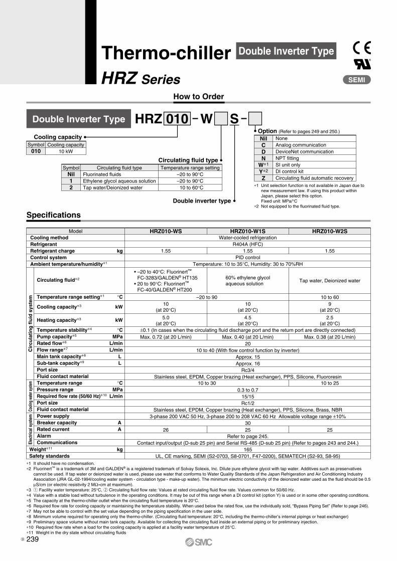
010 W SHRZDouble Inverter Type
Symbol010
Cooling capacity10 kW
Cooling capacity
Circulating fluid typeFluorinated fluidsEthylene glycol aqueous solutionTap water/Deionized water
Temperature range setting–20 to 90°C–20 to 90°C
10 to 60°C
SymbolNil12
Circulating fluid type
Double inverter type
NoneAnalog communicationDeviceNet communicationNPT fittingSI unit onlyDI control kitCirculating fluid automatic recovery
NilCDN
W∗1
Y∗2
Z
Option (Refer to pages 249 and 250.)
∗1 It should have no condensation.∗2 Fluorinert™ is a trademark of 3M and GALDEN® is a registered trademark of Solvay Solexis, Inc. Dilute pure ethylene glycol with tap water. Additives such as preservatives
cannot be used. If tap water or deionized water is used, please use water that conforms to Water Quality Standards of the Japan Refrigeration and Air Conditioning Industry Association (JRA GL-02-1994/cooling water system - circulation type - make-up water). The minimum electric conductivity of the deionized water used as the fluid should be 0.5 µS/cm (or electric resistivity 2 MΩ cm at maximum).
∗3 q Facility water temperature: 25°C, w Circulating fluid flow rate: Values at rated circulating fluid flow rate. Values common for 50/60 Hz.∗4 Value with a stable load without turbulence in the operating conditions. It may be out of this range when a DI control kit (option Y) is used or in some other operating conditions.∗5 The capacity at the thermo-chiller outlet when the circulating fluid temperature is 20°C.∗6 Required flow rate for cooling capacity or maintaining the temperature stability. When used below the rated flow, use the individually sold, “Bypass Piping Set” (Refer to page 246).∗7 May not be able to control with the set value depending on the piping specification in the user side.∗8 Minimum volume required for operating only the thermo-chiller. (Circulating fluid temperature: 20°C, including the thermo-chiller’s internal pipings or heat exchanger)∗9 Preliminary space volume without main tank capacity. Available for collecting the circulating fluid inside an external piping or for preliminary injection.∗10 Required flow rate when a load for the cooling capacity is applied at a facility water temperature of 25°C.∗11 Weight in the dry state without circulating fluids
Cooling methodRefrigerantRefrigerant charge kgControl systemAmbient temperature/humidity∗1
Circulating fluid∗2
Temperature range setting∗1 °C
Cooling capacity∗3 kW
Heating capacity∗3 kW
Temperature stability∗4 °CPump capacity∗5 MPaRated flow∗6 L/minFlow range∗7 L/minMain tank capacity∗8 L Sub-tank capacity∗9 L Port sizeFluid contact material Temperature range °CPressure range MPaRequired flow rate (50/60 Hz)∗10 L/minPort sizeFluid contact materialPower supplyBreaker capacity A Rated current A AlarmCommunications
Weight∗11 kgSafety standards
Water-cooled refrigerationR404A (HFC)
PID controlTemperature: 10 to 35°C, Humidity: 30 to 70%RH
Model HRZ010-WS HRZ010-W1S HRZ010-W2S
–20 to 90 10 to 60
±0.1 (In cases when the circulating fluid discharge port and the return port are directly connected)
2010 to 40 (With flow control function by inverter)
Approx. 15Approx. 16
Rc3/4Stainless steel, EPDM, Copper brazing (Heat exchanger), PPS, Silicone, Fluororesin
0.3 to 0.715/15Rc1/2
Stainless steel, EPDM, Copper brazing (Heat exchanger), PPS, Silicone, Brass, NBR3-phase 200 VAC 50 Hz, 3-phase 200 to 208 VAC 60 Hz Allowable voltage range ±10%
30
Refer to page 245.Contact input/output (D-sub 25 pin) and Serial RS-485 (D-sub 25 pin) (Refer to pages 243 and 244.)
165UL, CE marking, SEMI (S2-0703, S8-0701, F47-0200), SEMATECH (S2-93, S8-95)
10 to 30
10(at 20°C)
4.5(at 20°C)
Max. 0.40 (at 20 L/min)
25
9(at 20°C)
2.5(at 20°C)
Max. 0.38 (at 20 L/min)
10 to 25
25
60% ethylene glycolaqueous solution
Tap water, Deionized water
• –20 to 40°C: Fluorinert™
FC-3283/GALDEN® HT135• 20 to 90°C: Fluorinert™
FC-40/GALDEN® HT200
10(at 20°C)
5.0(at 20°C)
Max. 0.72 (at 20 L/min)
26
Cir
cula
tin
g f
luid
sys
tem
Cooli
ng w
ater s
ystem
Elec
trica
l sys
tem
1.55 1.551.55
Double Inverter Type®
SEMI
∗1 Unit selection function is not available in Japan due to new measurement law. If using this product within Japan, please select this option.Fixed unit: MPa/°C
∗2 Not equipped to the fluorinated fluid type.
239B

Thermo-chiller HRZ Series
HRZ010-WS/010-W1S HRZ010-W2S
HRZ010-WS/010-W1S/010-W2S
Cooling Capacity
Heating Capacity
HRZ010-WS HRZ010-W1S
HRZ010-W2S
Pump Capacity (Thermo-chiller Outlet)
12
10
8
6
4
2
0–20 –10 0 10 20 30 40 50 60 70 80 90
Circulating fluid temperature [°C]
Coo
ling
capa
city
[kW
]
HRZ010-WS/010-W1S
12
10
8
6
4
2
010 20 30 40 50 60
Circulating fluid temperature [°C]
Coo
ling
capa
city
[kW
]
HRZ010-W2S
0 10 20 30 40
0.5
0.4
0.3
0.2
0.1
0
50
40
30
20
10
0
∗ The pump capacity of the HRZ010-W1S is same as that of the HRZ001-L1 group on page 236.∗ The pump capacity of the HRZ010-W2S is same as on page 238.
∗ When pump inverter is operating at frequency of 60 Hz (maximum).
0 10 20 30 40
0.5
0.4
0.3
0.2
0.1
0
40
30
20
10
0
Circulating fluid temperature [°C]
Hea
ting
capa
city
[kW
]
7
6
5
4
3
2
1
0–20 –10 0 10 20 30 40 50 60 70 80 90
HRZ010-WS
HRZ010-W1S
HRZ010-W2S
0 10 20 30 400
0.1
0.2
0.3
0.4
0.5
0.6
0.7
0.8
0.9
1
50
40
30
20
10
0
Circulating fluid flow rate [L/min]
Lifting height[m]
Pressure[MPa]
[Outlet: Max.]
[Return port]
Circulating fluid flow rate [L/min]
Lifting height[m]
Pressure[MPa]
[Outlet: Max.]
[Return port]
Circulating fluid flow rate [L/min]
Lifting height[m]
Pressure[MPa]
[Outlet: Max.]
[Return port]
∗ When the circulating fluid flow is below 6 L/min, the in-built operation stop alarm will be activated. It is not possible to run the equipment. (common for all models)
∗ With flow control function by inverter
240
HR
SH
RS
090
HR
S100
/150
HR
SH
090
HR
SH
HR
SE
HR
ZH
RZ
DH
RW
HE
CR
HE
CH
ED
HE
BTe
chni
cal
Dat
a

HRZ Series
Common Specifications
Dimensions
SEL
ENT
ALARM
RUN
REMOTE
Rear side Front side
Rc3/4 (with plug)
Rc3/8 (with valve/plug)
Rc3/8 (with plug)
gauge
Breaker handle
55or less
Ventilation(expiration)
Refrigeranthigh pressure
Bolt for fixing the anti-quake bracketM8 stud bolt
DB A
C
Operation display panel
Emergency off [EMO] switch (Red, ø40 mm)With a guard ring (yellow)
Caster (unfixed)with brake
Caster (fixed)Bolt for fixing theanti-quake bracketM8 stud bolt
Sub-tank drain portRc3/8 (with valve/plug)
Facility water inletRc1/2 (with plug)
Facility wateroutletRc1/2 (with plug)
Model no. label
Power cable entry Cooling fan for the unit inside (exhaust)
85 or lessCirculating fluid fill port
Handle
Circulating fluid return portRc3/4 (with plug)
Circulating fluid level gauge
Circulating fluidoutlet
Main tank drain port
Drain pan port
Handle
HRZ001-HHRZ002-H
HRZ001-LHRZ002-L, WHRZ004-L, HHRZ008-H, WHRZ010-WS
HRZ001-L2HRZ002-L2HRZ004-L2HRZ008-L2HRZ010-W2S
HRZ001-H1HRZ002-H1
HRZ001-L1HRZ002-L1, W1HRZ004-L1, H1HRZ008-H1, W1HRZ010-W1S
A
[mm]
380
380
B C
860
950
D
ø18.5 to 20.5
ø18.5 to 20.5
870
870
Model
Fluorinated fluid type Ethylene glycol type Tap/Deionized water type
—
(Dimensional tolerance of A, B, and C: ±10 mm)
241

A
C
B
987
375
325
53 1080
1157
1217
350
30
Anti-quake bracket
Level foot
Anchor bolt location8 x ø9
D
Rear side Front side
Power cable entry
Cooling fan for the unit inside (exhaust)
Model no. label
Facility wateroutletRc1/2 (with plug)
Facility water inletRc1/2 (with plug)
Drain pan portRc3/8 (with plug)
Sub-tank drain portRc3/8 (with valve/plug)
Main tank drain port
Rc3/8 (with valve/plug)
Circulating fluid outletRc3/4 (with plug)
Circulating fluid level gauge
Circulating fluid return portRc3/4 (with plug)
Handle
Circulating fluid fill port
Handle
85 mm or less55 mmor less
Operation display panel Breaker handle
Ventilation(expiration)
Refrigeranthigh pressuregauge
Emergency off [EMO] switch (Red, ø40 mm)With a guard ring (yellow)
Caster (unfixed)Caster (unfixed)
Level foot
Anti-quake bracket mounting position (Dimensional tolerance: ±5 mm)
∗ Anchor bolts (M8, 8 pcs.) which are suitable for the floor material should be prepared by user.
HRZ008-L HRZ008-L1
A
[mm]
415
B C
1075
D
ø35.0 to 38.01080
(Dimensional tolerance of A, B, and C: ±10 mm)
Model
Fluorinated fluid type Ethylene glycol type
Common Specifications HRZ Series
242
HR
SH
RS
090
HR
S100
/150
HR
SH
090
HR
SH
HR
SE
HR
ZH
RZ
DH
RW
HE
CR
HE
CH
ED
HE
BTe
chni
cal
Dat
a

HRZ Series
Communication Functions (For details, please refer to our “Communication Specifications” information.)
4.7 kΩ
3
2
4.7 kΩ
16
4.7 kΩ
4
4.7 kΩ
17
6
19
7
20
8
5
18
13
15
14
25
INT 24 COM
1INT 24 VDC
To the thermo-chiller User’s equipment side
Pin assignment number
Run/Stop signal
—
—
Recovery signal
Run/Stop signal 1
Run/Stop signal 2
DIO REMOTEsignal 2
DIO REMOTEsignal 1
Item
Contact Input/Output
Connector no.
Connector type (on this product’s side)
Fixing bolt size
Insulation method
Rated input voltage
Operating voltage range
Rated input current
Input impedance
Insulation method
Rated load voltage
Operating load voltage range
Maximum load current
Leakage current
Surge protection
Rated load voltage
Maximum load current
Rated load voltage
Maximum load current
Input signal
Open collector output signal
Contact output signal(Alarm signal)
Contact output signal(EMO signal)
Specifications
P1 (Refer to page 244 for the connector location.)
D-sub 25 P type, Female connector
M2.6 x 0.45
Photocoupler
24 VDC
21.6 VDC to 26.4 VDC
5 mA TYP
4.7 kΩ
Photocoupler
24 VDC
21.6 VDC to 26.4 VDC
80 mA
0.1 mA or less
Diode
48 VAC or less/24 VDC or less
500 mA AC/DC (Resistance load)
48 VAC or less/24 VDC or less
800 mA AC/DC (Resistance load/Inductive load)
Circuit diagram
∗1 When using the power supply of the thermo-chiller, short circuit pins 1 and 2 and pins 14 and 15 respectively.When using the power supply of the user’s equipment, connect the lead wires to pins 2 and 15 and short circuit pins 14 and 15. Incorrect connections may cause a malfunction.
∗2 The custom function is equipped for contact input/output. Using the custom function enables the user to set the signal type for contact input/output or pin assignment numbers. For details, please refer to the “Communication Specifications” information.
Internalcircuit
24 VDC output (Output from the thermo-chiller)
24 COM output (Output from the thermo-chiller)
24 VDC input (Supply from the user’s equipment or thermo-chiller)∗1
24 COM input (Supply from the user’s equipment or thermo-chiller)∗1
Setting at the time ofshipment from factory Custom function∗2
Inpu
t sig
nal
Operation conditionsignal
Warning signal
Fault signal
Remote signal
Temp ready signal
Alarm signal
EMO signal
Output signal 1
Output signal 2
Output signal 3
Output signal 4
Output signal 5
Alarm signal
EMO signal
Out
put s
igna
l
Emergency off[EMO] switch
243A

SMC
ESOLC
NEPO
Rear side
Internal circuit
To the thermo-chiller User’s equipment side
5
7
2
The serial RS-485 enables the following items to be written and read out.<Writing> Run/Stop Circulating fluid temperature setting Circulating fluid automatic recovery start/stop∗1
<Readout> Circulating fluid present temperature Circulating fluid flow Circulating fluid discharge pressure Circulating fluid electric resistivity∗2
Alarm occurrence informationStatus (operating condition) information
∗1 Only when the circulating fluid automatic recovery function (option Z) is selected.
∗2 Only when the DI control kit (option Y) is selected.
Serial RS-485Item Specifications
Connector no.
Connector type (on this product’s side)
Fixing bolt size
Standards
Protocol
Circuit diagram
P2
D-sub 9 P type, Female connector
M2.6 x 0.45
EIA RS485
Modicon Modbus
SD+
SD–
SG
Connector LocationP3: Not used for the maintenance purpose portD-sub 9 (Male receptacle)
P2: Serial RS-485D-sub 9 (Female receptacle)
P1: Contact input/outputD-sub 25 (Female receptacle)
Power cable entry
Common Specifications HRZ Series
244
HR
SH
RS
090
HR
S100
/150
HR
SH
090
HR
SH
HR
SE
HR
ZH
RZ
DH
RW
HE
CR
HE
CH
ED
HE
BTe
chni
cal
Dat
a

Alarm
Operation Display Panel
REMOTE
RUN
A L A RM
S EL
EN T
START/STOP
RESET
q
w
e
u
y
t
r
!0
o
i
TEMP PV 20.0 °CFLOW PV 20.2 LPMPRESS. 0.56 MPa
DescriptionNo. Function
[START/STOP] key
[RESET] key
[SEL] key
[ENT] key
[] [] key
[] key
[REMOTE] lamp
[RUN] lamp
[ALARM] lamp
Operating condition of this unit/Circulating fluid discharge temperature/Circulating fluid flow/ Circulating fluid discharge pressure/Setting value/Alarm message, etc. are displayed.
Starts/Stops the operation.
Stops the alarm buzzing. Resets the alarm.
Switches the display.
Decides the settings.
Moves the cursor and changes the setting values.
Moves the cursor.
Lights up when the unit is in the remote status.
Lights up when the unit is in the operating status.
Lights up when the unit is alarming.
LCD
This unit can display 28 kinds of alarm messages as standard. Also, it can read out the serial RS-485 communication.
Alarm code Alarm messageOperation
status Main reason
01
02
03
04
05
06
07
08
09
11
12
13
14
15
16
17
18
19
20
21
22
23
24
25
26
27
28
Water Leak Detect FLT
Incorrect Phase Error FLT
RFGT High Press FLT
CPRSR Overheat FLT
Reservoir Low Level FLT
Reservoir Low Level WRN
Reservoir High Level WRN
Temp. Fuse Cutout FLT
Reservoir High Temp. FLT
Reservoir High Temp. WRN
Return Low Flow FLT
Return Low Flow WRN
Heater Breaker Trip FLT
Pump Breaker Trip FLT
CPRSR Breaker Trip FLT
Interlock Fuse Cutout FLT
DC Power Fuse Cutout WRN
FAN Motor Stop WRN
Internal Pump Time Out WRN
Controller Error FLT
Memory Data Error FLT
Communication Error WRN
DI Low Level WRN
Pump Inverter Error FLT
DNET Comm. Error WRN
DNET Comm. Error FLT
CPRSR INV Error FLT
Stop
Stop
Stop
Stop
Stop
Continue
Continue
Stop
Stop
Continue
Stop
Continue
Stop
Stop
Stop
Stop
Continue
Continue
Continue
Stop
Stop
Continue
Continue
Stop
Continue
Stop
Stop
Liquid deposits in the base of this unit.
The power supply to this unit is incorrect.
Pressure in the refrigeration circuit has exceeded the limitation.
Temperature inside the compressor has increased.
The amount of circulating fluid is running low.
The amount of circulating fluid is running low.
Filling the circulating fluid too much.
Temperature of the circulating fluid tank is raised.
Temperature of the circulating fluid has exceeded the limitation.
Temperature of the circulating fluid has exceeded the limitation set by user.
The circulating fluid flow has gone below 6 L/min.
The circulating fluid flow has gone below the limitation set by user.
Protection device for the electric circuit of the heater is activated.
Protection device for the electric circuit of the circulating pump is activated.
Protection device for the electric circuit of the compressor is activated.
Overcurrent is flown to the control circuit.
Overcurrent has flowed to the (optional) solenoid valve.
Cooling fan inside the compressor has stopped.
The internal pump continuously run for more than a certain period of time.
The error occurred in the control systems.
The data stored in the controller of this unit went wrong.
The serial communications between this unit and user’s system has been suspended.
DI level of the circulating fluid has gone below the limitation set by user. (Option)
An error has occurred in the inverter for the circulating pump.The alarm is only for the HRZ010-WS.
The DeviceNet communications between this unit and user’s system has been suspended. (Only for DeviceNet communication specification - option D)
An error has occurred in the DeviceNet communication system of this unit. (Only for DeviceNet communication specification - option D)
An error has occurred in the inverter for the compressor.The alarm is only for the HRZ010-WS.
HRZ Series
245

q Bypass Piping Set ∗ Necessary to be fitted by user.
w Anti-quake Bracket
Front side
Anchor bolt (M12)
Anti-quake bracket HRZ-TK002
2 pieces per set (4 nuts are included.)
160
111
904
Nut (M8) x 2(Accessory to anti-quake bracket)
• Fit it on the opposite side similarly.
When the circulating fluid goes below the rated flow, cooling capacity will be reduced and the temperature stability will be badly affected.In such a case, use the bypass piping set.
Approx. 126 mmMounting view (Rear side)
To circulating fluidreturn port 2 x Rc3/4
To circulating fluidoutlet
Bypass volume adjustment valve
Insulatingmaterial
Part no.
HRZ-BP001
HRZ-BP002
HRZ-BP008
Applicable model
HRZ001-H/HRZ001-H1HRZ002-H/HRZ002-H1
HRZ001-L/HRZ001-L1HRZ001-L2
HRZ002-L/HRZ002-L1HRZ002-L2
HRZ004-L/HRZ004-L1HRZ004-L2HRZ008-L2
HRZ004-H/HRZ004-H1HRZ008-H/HRZ008-H1HRZ002-W/HRZ002-W1HRZ008-W/HRZ008-W1
HRZ010-WSHRZ010-W1SHRZ010-W2S
HRZ008-L/HRZ008-L1
Bracket for earthquakesPrepare the anchor bolts (M12) which are suited to the floor material by user.
Part no.
HRZ-TK002
Applicable model
HRZ001-L/HRZ002-L/HRZ004-L/HRZ008-L2HRZ001-H/HRZ002-HHRZ004-H/HRZ008-H
HRZ002-W/HRZ008-W/HRZ010-WS
∗ 2 pieces per set (for 1 unit) (HRZ-TK002) ∗ Anti-quake bracket is attached as standard. (HRZ008-L, HRZ008-L1)
Anchor bolt location4 x ø14Top side
Front side
Anti-quake bracket
HRZ Series
Optional Accessories
246
HR
SH
RS
090
HR
S100
/150
HR
SH
090
HR
SH
HR
SE
HR
ZH
RZ
DH
RW
HE
CR
HE
CH
ED
HE
BTe
chni
cal
Dat
a

e 4-Port Manifold
Part no.
HRZ-MA001Applicable model
Common for all models
4-branching the circulating fluid enables 4 temperature controls at the maximum with the 1 unit thermo-chiller.
Mounting view (Rear side) Approx. 210 mm
4 x Rc1/2
2 pcs./set
r DI Filter
HRZ-DF001
This is the ion replacement resin to maintain the electric resistivity of the circulating fluid.Users who selected the DI control kit (option Y) need to purchase the DI filter separately.
∗ The DI filters are consumable. Depending on the status (electric resistivity set value, circulating fluid temperature, piping volume, etc.), product life cycles will vary accordingly.
Part no. Applicable model
Common for all models which can selectthe DI control kit. (option Y)
t Insulating Material for DI Filter
HRZ-DF002
When the DI filter is used at a high-temperature, we recommend that you use this insulating material to protect the radiated heat from the DI filter or possible burns. When the DI filter is used at a low-temperature, we also recommend that you use this to prevent heat absorption from the DI filter and to avoid forming condensation.
Part no. Applicable model
Common for all models which can selectthe DI control kit. (option Y)
App
rox.
508
mm
Approx.ø220 mm
Weight: Approx. 20 kg
HRZ Series
247

Approx. 170 mm
App
rox.
280
mm
Approx. 230 mm
Approx. 230 mm
App
rox.
35
mm
y 60% Ethylene Glycol Aqueous Solution u Concentration Meter
This solution can be used as a circulating fluid for ethylene glycol-type thermo-chillers. (Capacity: 10 L)
Part no.
HRZ-BR001Applicable model
Common for all ethylene glycol-type models
This meter can be used to control the condensation of ethylene glycol solution regularly.
Part no.
HRZ-BR002Applicable model
Common for all ethylene glycol-type models
Optional Accessories HRZ Series
248
HR
SH
RS
090
HR
S100
/150
HR
SH
090
HR
SH
HR
SE
HR
ZH
RZ
DH
RW
HE
CR
HE
CH
ED
HE
BTe
chni
cal
Dat
a

HRZ Series
Options
Rc3/4
DI tube(1 piece each attached for IN/OUT)
DI filter(Optional accessories)
(Refer to page 247.)∗ Please order separately.
Approx.156 mm
Analog CommunicationOption symbol
C
CHRZ
DeviceNet CommunicationOption symbol
D
DHRZ
DI Control KitOption symbol
Y
YHRZ
NPT FittingOption symbol
N SI Unit OnlyOption symbol
W
NHRZ
Analog communication
In addition to the standard contact input/output signal communication and the serial RS-485 communication, analog communication function can be added.The analog communication function enables to write and read out the following items.
<Writing> Circulating fluid temperature setting
Scaling voltage - circulating fluid temperature can be set arbitrarily by user.For details, please refer to our “Communication Specifications” information.
<Readout>Circulating fluid present temperature Electric resistivity∗1
∗1 Only when the DI control kit (option Y) is selected.
DeviceNetcommunication
In addition to the standard contact input/output signal communication and the serial RS-485 communication, DeviceNet function can be added.DeviceNet function enables to write and read out the following items.
<Writing>Run/Stop Circulating fluid temperature setting Circulating fluid automatic recoverystart/stop∗1
∗1 Only when the circulating fluid automatic recovery function (option Z) is selected. ∗2 Only when the DI control kit (option Y) is selected.
For details, please refer to our “Communication Specifications” information.
<Readout>Circulating fluid present temperature Circulating fluid flow Circulating fluid discharge pressure Electric resistivity∗2 Alarm occurrence informationStatus (operating condition) information
NPT fitting
An adapter is included to change the connection parts of circulating fluid piping and facility water piping to NPT thread type. The adapter must be installed by user.
DI control kit
Select this option if you want to maintain the electric resistance ratio (DI level) of the circulating fluid at a certain level. However, some components have to be fitted by user. For details, refer to specification table for this option.Please note that this is not applicable to the fluorinated liquid type.
60% ethylene glycol aqueous solution
0 to 20
0 to 2.0∗1
0 to 2.0
HRZ00-L1-YHRZ00-H1-YHRZ00-W1-YHRZ010-W1S-Y
HRZ00-L2-YHRZ010-W2S-Y
Allowable circulating fluid
DI level display range
DI level set range
DI level reduction alarm set range
—
MΩ·cm
MΩ·cm
MΩ·cm
Applicable model
Deionized water
∗1 The DI filter is needed to control the DI level. (SMC Part No.: HRZ-DF001) Please purchase additionally because the DI filter is not included in this option. Also, if necessary, additionally purchase the insulating material for the DI filter. (SMC Part No.: HRZ-DF002)
∗ Install the DI filter outside the thermo-chiller for piping. Secure the space for installing the DI filter on the rear side of the thermo-chiller.
∗ It may go outside of the temperature stability range of ±0.1°C when this option is used in some operating conditions.
∗ Options have to be selected when ordering the thermo-chiller. It is not possible to add them after purchasing the unit.
TrademarkDeviceNet™ is a trademark of ODVA.
The circulating fluid temperature and pressure are displayed in SI units only.Unit selection function is not available in Japan due to new measurement law.If using this product within Japan, please select this option.Fixed unit: MPa/°CIf this option is not selected, a product with a unit selection function will be provided by default.∗ No change in external dimensions
WHRZ
SI unit only
249A

Circulating Fluid Automatic RecoveryOption symbol
Z
ZHRZCirculating fluid
automatic recovery
Select this option for users who want to use the circulating fluid automatic recovery function.The automatic recovery function is a device which can recover the circulating fluid inside pipings into a sub-tank of the thermo-chiller by the external communication or operating display panel. Some components need to be fitted by user. For details, please refer to the “Product Specifications” information for these options.
15 16 17
HRZ001-H-ZHRZ001-H1-ZHRZ002-H-ZHRZ002-H1-Z
HRZ001-L-Z HRZ001-L1-ZHRZ002-L-Z HRZ002-L1-ZHRZ004-L-Z HRZ004-L1-ZHRZ004-H-Z HRZ004-H1-ZHRZ008-H-Z HRZ008-H1-ZHRZ001-L2-Z HRZ002-L2-ZHRZ004-L2-Z HRZ008-L2-ZHRZ002-W-Z HRZ002-W1-ZHRZ008-W-Z HRZ008-W1-ZHRZ010-WS-Z HRZ010-W1S-ZHRZ010-W2S-Z
HRZ008-L-ZHRZ008-L1-Z
Circulating fluid recoverable volume∗1
Purge gas
Purge gas supply port
Purge gas supply pressure
Purge gas filtration
Regulator set pressure
Recoverable circulating fluid temperature
Recovery start/stop
Timeout error
Height difference with the user system side
Applicable model
L
—
—
MPa
µm
MPa
°C—
sec
m
Nitrogen gas
Self-align fitting for O.D. ø8∗2
0.4 to 0.7
0.01 or less
0.15 to 0.3∗3
10 to 30
Start: External communication∗4 or operation display panel/Stop: Automatic
10 or less
Timer from recovery start to completionStops recovering when the timer turns to set time.
Possible set range: 60 to 300, at the time of shipping from the factory: 300
∗1 This is the space volume of the sub-tank when the liquid level of the circulating fluid is within the specification. Guideline of the recovery volume is 80% of the circulating fluid recoverable volume. ∗2 Before piping, clean inside the pipings with air blow, etc. Use the piping with no dust generation by purge gas. When using resin tube, where necessary, use insert fittings, etc. in order not to deform the tubings when connecting to self-align fittings. ∗3 At the time of shipping from factory, it is set to 0.2 MPa.∗4 For details, please refer to our “Communication Specifications” information.
Rc3/4
Approx.110 mm
Options HRZ Series
250
HR
SH
RS
090
HR
S100
/150
HR
SH
090
HR
SH
HR
SE
HR
ZH
RZ
DH
RW
HE
CR
HE
CH
ED
HE
BTe
chni
cal
Dat
a

HRZ SeriesSpecific Product Precautions 1
Sta
ndar
d ite
mR
efer
ence
item
Item
pH (at 25°C)
Electric conductivity (25°C)
Chloride ion (Cl–)
Sulfuric acid ion (SO42–)
Acid consumption amount (at pH4.8)
Total hardness
Calcium hardness (CaCO3)
Ionic state silica (SiO2)
Iron (Fe)
Copper (Cu)
Sulfide ion (S2–)
Ammonium ion (NH4+)
Residual chlorine (Cl)
Free carbon (CO2)
Unit
—
[µS/cm]
[mg/L]
[mg/L]
[mg/L]
[mg/L]
[mg/L]
[mg/L]
[mg/L]
[mg/L]
[mg/L]
[mg/L]
[mg/L]
[mg/L]
Standard value
Influence
CorrosionScale
generation
6.0 to 8.0
100∗1 to 300∗1
50 or less
50 or less
50 or less
70 or less
50 or less
30 or less
0.3 or less
0.1 or less
Should not be detected.
0.1 or less
0.3 or less
4.0 or less
∗1 In the case of [MΩ·cm], it will be 0.003 to 0.01. : Factors that have an effect on corrosion or scale generation. Even if the water quality standards are met, complete prevention of corrosion
is not guaranteed.
Design
Warning1. This catalog shows the specifications of a single unit.
1. For details, please refer to our “Product Specifications” and thoroughly consider the adaptability between the user’s system and this unit.
2. Although the protection circuit as a single unit is installed, the user is requested to carry out the safety design for the whole system.
Selection
Caution
Handling
Warning1. Thoroughly read the Operation Manual.
Read the Operation Manual completely before operation, and keep this manual available whenever necessary.
1. Model selectionIn order to select the correct thermo-chiller model, the amount of thermal generation from the user’s system, the operating circulating fluid, and its circulating flow are required. Select a model, by referring to the guideline to model selection on page 227.
2. Option selectionOptions have to be selected when ordering the thermo-chiller. It is not possible to add them after purchasing the unit.
Operating Environment/Storage Environment
Caution1. Do not use in the following environment
because it will lead to a breakdown. 1. Environment like written in “Temperature Control Equipment
Precautions.”2. Locations where spatter will adhere to when welding.3. Locations where it is likely that the leakage of flammable gas
may occur.4. Locations where the ambient temperature exceeds the limits
as mentioned below.During operation 10°C to 35°CDuring storage 0°C to 50°C (but as long as water or circulating fluid are not left inside the pipings)
5. Locations where the ambient relative humidity exceeds the limit as mentioned below.
During operation 30% to 70%During storage 15% to 85%
6. (Inside the operation facilities) locations where there is not sufficient space for maintenance.
7. In locations where the ambient pressure exceeds the atmospheric pressure.
2. The Thermo-chiller does not have clean room specification. It generates dust from the pump inside the unit and the cooling fan for the unit inside.
Circulating Fluid
Caution1. Avoid oil or other foreign matter entering the
circulating fluid.
Circulating Fluid
Tap Water (as Circulating Water) Quality StandardsThe Japan Refrigeration and Air Conditioning Industry AssociationJRA GL-02-1994 “Cooling water system – Circulating type – Supply water”
2. Use ethylene glycol that does not contain additives such as preservatives.
3. The condensation of ethylene glycol aqueous solution must be 60% or less. If the density is too high, the pump will be overloaded, resulting in occurrence of “Pump Breaker Trip FLT.” Also, if the density is to low, the unit will freeze at lower temperatures, resulting in product failure.
4. Avoid water moisture entering the fluorinated fluid. Otherwise, the unit will freeze, resulting in product failure.
5. Use tap water (including for diluting ethylene glycol aqueous solution) which must meet the water quality standards as mentioned below.
Be sure to read this before handling the products. Refer to page 383 for safety instructions and pages 384 to 387 for temperature control equipment precautions.
251

Mounting/Installation
Caution1. Avoid using this product outdoors. 2. Install on a rigid floor which can withstand this
product’s weight.3. Install a suitable anchor bolt for the anti-quake bracket
taking into consideration the user’s floor material.4. Avoid placing heavy objects on this product.
Piping
Caution1. Regarding the circulating fluid pipings, consider carefully the
suitability for shutoff pressure, temperature and circulating fluid.If the operating performance specifications are regularly exceeded, the pipings may burst during operation.
2. The surface of the circulating fluid pipings should be covered with the insulating materials which can effectively confine the heat.Absorbing the heat from the surface of pipings may reduce the cooling capacity performance and the heating capacity may be shortened due to heat radiation.
3. When using fluorinated liquid as the circulating fluid, do not use pipe tape. Liquid leakage may occur around the pipe tape.For sealant, we recommend that you use the following sealant: SMC Part No., HRZ-S0003 (Silicone sealant)
4. For the circulating fluid pipings, use clean pipings which have no dust, oil or water moisture inside the pipings, and blow with air prior to undertaking any piping works.If any dust, oil or water moisture enters the circulating fluid circuit, inferior cooling performance or equipment failure due to frozen water may occur, resulting in bubbles in the circulating fluid inside the tank.
5. The reciprocating total volume of the circulating fluid pipings must be less than the volume of the sub-tank.Otherwise, when the equipment is stopped, the in-built alarm may activate or the circulating fluid may leak from the tank. Refer to the specifications table for the sub-tank volume.
6. Select the circulating fluid pipings which can exceed the required rated flow.For the rated flow, refer to the pump capacity table.
7. For the circulating fluid piping connection, install a drain pan just in case the circulating fluid may leak.
8. Do not return the circulating fluid to the unit by installing a pump in the user system.
HRZ SeriesSpecific Product Precautions 2
Transportation/Carriage/Movement
Warning1. Transporting with forklift
1. It is not possible to hang this product.2. The fork insertion position is either on the left side face or
right side face of the unit. Be careful not to bump the fork against a caster or level foot and be sure to put through the fork to the opposite side.
3. Be careful not to bump the fork to the cover panel or piping ports.
2. Transporting with casters1. This product is heavy
and should be moved by at least two people.
2. Do not grip the pipings on the rear side or the handles of the panel.
Fork insertionside
Front side
Fork insertion sideRear side
Warning<Water-cooled refrigeration>1. The water-cooled refrigeration type thermo-chiller
radiates heat to the facility water.Prepare the facility water system that satisfies the facility water specifications below.
2. When using tap water as facility water, use tap water that conforms to the appropriate water quality standards.Use tap water that conforms to the standards shown below.
Facility Water Supply
3. Set the supply pressure between 0.3 to 0.7 MPa. Ensure a pressure difference at the facility water inlet/outlet of 0.3 MPa or more.If the supply pressure is high, it will cause water leakage. If the supply pressure and pressure difference at the facility water inlet/outlet is low, it will cause an insufficient flow rate of the facility water, and poor temperature control.
The Japan Refrigeration and Air Conditioning Industry AssociationJRA GL-02-1994 “Cooling water system – Circulation type – Circulating water”
<Tap Water (as Facility Water) Quality Standards>
Sta
ndar
d it
emR
efer
ence
item
Item
pH (at 25°C)Electric conductivity (25°C)Chloride ion (Cl−)Sulfuric acid ion (SO4
2−)Acid consumption amount (at pH4.8)Total hardnessCalcium hardness (CaCO3)Ionic state silica (SiO2)Iron (Fe)Copper (Cu)Sulfide ion (S2
−)Ammonium ion (NH4
+)Residual chlorine (Cl)Free carbon (CO2)
Unit
—[µS/cm][mg/L][mg/L][mg/L][mg/L][mg/L][mg/L][mg/L][mg/L][mg/L][mg/L][mg/L][mg/L]
Standard value
Influence
CorrosionScale
generation
6.5 to 8.2100∗1 to 800∗1
200 or less200 or less100 or less200 or less150 or less50 or less1.0 or less0.3 or less
Should not be detected.1.0 or less0.3 or less4.0 or less
∗1 In the case of [MΩ·cm], it will be 0.001 to 0.01. : Factors that have an effect on corrosion or scale generation. Even if the water quality standards are met, complete prevention of corrosion
is not guaranteed.
Be sure to read this before handling the products. Refer to page 383 for safety instructions and pages 384 to 387 for temperature control equipment precautions.
Electrical Wiring
Caution1. Power supply and signal cable should be pre-
pared by user. 2. Provide a stable power
supply which is not affect-ed by surge or distortion.If the voltage increase ratio (dV/dt) at the zero cross should exceed 40 V/200 µsec., it may result in malfunction.
Voltage
Voltageincreaseratio
Time
252
HR
SH
RS
090
HR
S100
/150
HR
SH
090
HR
SH
HR
SE
HR
ZH
RZ
DH
RW
HE
CR
HE
CH
ED
HE
BTe
chni
cal
Dat
a
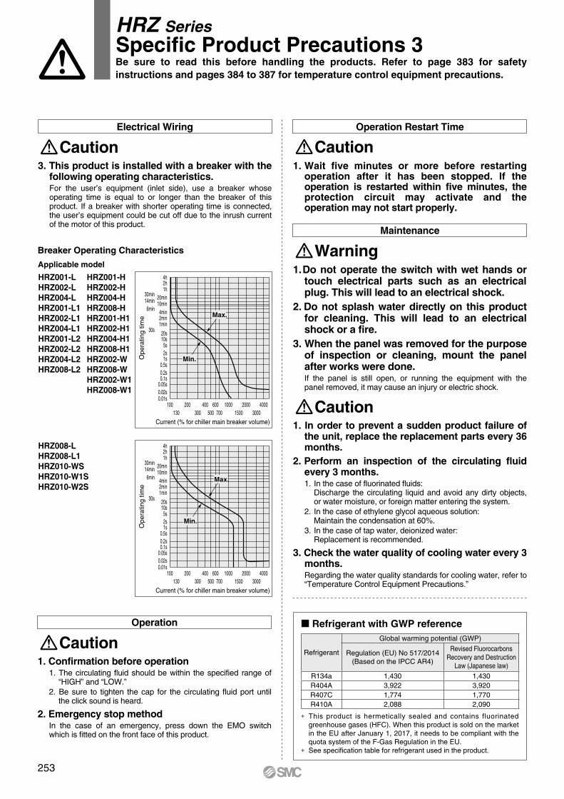
Operation
Caution1. Confirmation before operation
1. The circulating fluid should be within the specified range of “HIGH” and “LOW.”
2. Be sure to tighten the cap for the circulating fluid port until the click sound is heard.
2. Emergency stop method In the case of an emergency, press down the EMO switch which is fitted on the front face of this product.
Operation Restart Time
Caution1. Wait five minutes or more before restarting
operation after it has been stopped. If the operation is restarted within five minutes, the protection circuit may activate and the operation may not start properly.
Maintenance
Warning1. Do not operate the switch with wet hands or
touch electrical parts such as an electrical plug. This will lead to an electrical shock.
2. Do not splash water directly on this product for cleaning. This will lead to an electrical shock or a fire.
3. When the panel was removed for the purpose of inspection or cleaning, mount the panel after works were done.If the panel is still open, or running the equipment with the panel removed, it may cause an injury or electric shock.
Caution1. In order to prevent a sudden product failure of
the unit, replace the replacement parts every 36 months.
2. Perform an inspection of the circulating fluid every 3 months. 1. In the case of fluorinated fluids:
Discharge the circulating liquid and avoid any dirty objects, or water moisture, or foreign matter entering the system.
2. In the case of ethylene glycol aqueous solution:Maintain the condensation at 60%.
3. In the case of tap water, deionized water:Replacement is recommended.
3. Check the water quality of cooling water every 3 months. Regarding the water quality standards for cooling water, refer to “Temperature Control Equipment Precautions.”
HRZ SeriesSpecific Product Precautions 3
4h2h1h
0.01s0.02s0.05s
0.1s0.2s0.5s
1s2s5s
10s20s30s
1min2min4min6min
10min14min 20min30min
100 200 400 600 1000 2000 4000130 300 500 700 1500 3000
Max.
Min.
Current (% for chiller main breaker volume)
Ope
ratin
g tim
e
4h2h1h
0.01s0.02s0.05s
0.1s0.2s0.5s
1s2s5s
10s20s30s
1min2min4min6min
10min14min 20min30min
100 200 400 600 1000 2000 4000130 300 500 700 1500 3000
Current (% for chiller main breaker volume)
Ope
ratin
g tim
e
Max.
Min.
3. This product is installed with a breaker with the following operating characteristics. For the user’s equipment (inlet side), use a breaker whose operating time is equal to or longer than the breaker of this product. If a breaker with shorter operating time is connected, the user’s equipment could be cut off due to the inrush current of the motor of this product.
Electrical Wiring
Caution
Breaker Operating Characteristics
HRZ001-LHRZ002-LHRZ004-LHRZ001-L1HRZ002-L1HRZ004-L1HRZ001-L2HRZ002-L2HRZ004-L2HRZ008-L2
HRZ001-HHRZ002-HHRZ004-HHRZ008-HHRZ001-H1HRZ002-H1HRZ004-H1HRZ008-H1HRZ002-WHRZ008-WHRZ002-W1HRZ008-W1
HRZ008-LHRZ008-L1HRZ010-WSHRZ010-W1SHRZ010-W2S
Applicable model
Be sure to read this before handling the products. Refer to page 383 for safety instructions and pages 384 to 387 for temperature control equipment precautions.
253
Refrigerant with GWP reference
Refrigerant
Global warming potential (GWP)
Regulation (EU) No 517/2014(Based on the IPCC AR4)
Revised Fluorocarbons Recovery and Destruction
Law (Japanese law)
R134a 1,430 1,430R404A 3,922 3,920R407C 1,774 1,770R410A 2,088 2,090
* This product is hermetically sealed and contains fluorinated greenhouse gases (HFC). When this product is sold on the market in the EU after January 1, 2017, it needs to be compliant with the quota system of the F-Gas Regulation in the EU.
* See specification table for refrigerant used in the product.