Embed Size (px)
Citation preview
CAT.ES30-8 A
Refrigerated Air Dryer
IDF1EIDF2EIDF3EIDF4EIDF6EIDF8EIDF11E
0.100.200.320.520.751.221.65
0.120.2350.370.570.821.321.82
0.75 1.5 2.2 3.7 5.5 7.511
Rc3/8
Rc1/2
Rc3/4
HFC134aSaturation:
35°C0.7MPa
Standard inletair temperature
IDF
IDU3EIDU4EIDU6E
0.320.520.75
0.370.570.82
2.2 3.7 5.5
Rc3/8Rc1/2Rc3/4
HFC134aSaturation:
55°C0.7MPa
P.5-P.7
High inlet airtemperature
IDU
P.2-P.4
SeriesAir flow capacity m3/min (ANR)
50 Hz 60 HzApplicable air compressor output (Guide)
In case of screw type (kW) Port size PagesRefrigerantRated inletcondition
Increased up to the
max. 40%
Decreased up to the
max. 40%
Series IDF/IDU E
HFC134aCoefficient of destruction for ozone is zero.
Improved corrosion resistance with the use of stainless steel, plate type heat exchanger (Except IDF1E to 3E)
Air flow capacity
Power consumption
Refrigerant
IDF_IDU.qxd 04.8.23 4:33 PM ページ 1
1
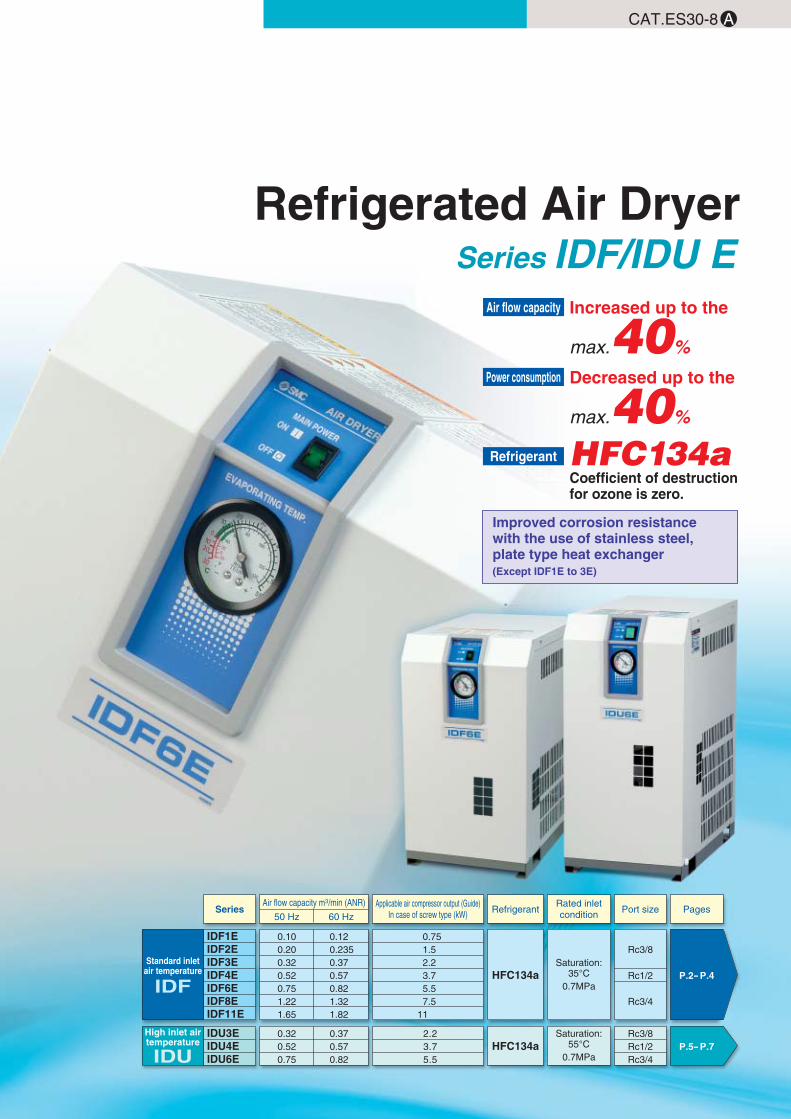
Series IDF/IDU ESelection Method
IDF selection example IDU selection exampleReading correction factor
Inlet air temperature (°C)
1.73
1.3
1
0.82
0.68
0.57
253035404550
Inlet air temperature (°C)
1.15
1.07
1
0.95
0.9
0.86
0.82
0.79
4550556065707580
Ambient temperature (°C)
1.14
1.04
1
0.96
0.9
2530323540
Model IDF1E0.10
0.12
IDF2E0.20
0.235
IDF3E0.32
0.37
IDF4E0.52
0.57
IDF6E0.75
0.82
IDF8E1.22
1.32
IDF11E1.65
1.82
Inlet air pressurem3/min (ANR)
50 Hz
60 Hz
Model IDU3E0.32
0.37
IDU4E0.52
0.57
IDU6E0.75
0.82
Inlet air pressurem3/min (ANR)
50 Hz
60 Hz
Ambient temperature (°C)
1.2
1.04
1
0.93
0.84
2530323540
Correctionfactor
Correctionfactor
Correctionfactor
Correctionfactor
Correctionfactor
0.59
1
1.68
51015
Inlet air pressure (MPa)
0.20.30.40.50.60.70.80.91
0.62
0.72
0.81
0.88
0.95
1
1.06
1.11
1.16
Outlet air pressure dew point (°C)
Data � Inlet air temperature
Series IDF Series IDU
Data � Ambient temperature
Series IDF
Data � Air flow capacity
Series IDF
Series IDU
Series IDU
Data � Outlet air pressure dew point Data � Inlet air pressure
Series IDF, IDU Series IDF, IDU
Obtain the correction factor � to � suitable for your operating condition from the graph at left.
1
Calculating corrected air flow capacity
Obtain the corrected air flow capacity from the following formula.
Corrected air flow capacity = Operating air flow capacity � (Correction factor � x � x � x �)
Corrected air flow capacity = 0.3 m3/min � (0.82 x 0.96 x 1 x 0.88) = 0.43 m3/min
Corrected air flow capacity = 0.4 m3/min � (0.95 x 0.93 x 1 x 0.88) = 0.51 m3/min
2
Selecting a modelSelect a model which corrected air flow capacity exceeds the air flow capacity from the specification table. (For air flow capacity, refer to the data below �.)
According to the corrected air flow capacity of 0.43 m3/min, IDF4E will be selected which air flow capacity is 0.52 m3/min at 50 Hz.
According to the corrected air flow capacity of 0.51 m3/min, IDU4E will be selected which air flow capacity is 0.57 m3/min at 60 Hz.
3
Selecting the type of threads, options and inter-national standards or not.
Refer to page 2 and 8. Refer to page 5 and 8.4
Model determination Refer to page 2. Refer to page 5.5Selecting accessories sold separately. Refer to page 10.6
40°C
35°C
10°C
0.5 MPa
0.3 m3/min
50 Hz
A
B
C
D
—
—
0.82
0.96
1
0.88
—
—
Inlet air temperature
Ambient temperature
Outlet air pressure dew point
Inlet air pressure
Air flow rate
Power supply frequency
Condition
Note) Values obtained from the table below.
60°C
35°C
10°C
0.5 MPa
0.4 m3/min
60 Hz
A
B
C
D
—
—
0.95
0.93
1
0.88
—
—
Inlet air temperature
Ambient temperature
Outlet air pressure dew point
Inlet air pressure
Air flow rate
Power supply frequency
Condition
Note) Values obtained from the table below.
Correctionfactor
Correctionfactor
Note) Correctionfactor
Datasymbol
Datasymbol
Note)
IDF_IDU.qxd 04.8.23 4:33 PM ページ 2
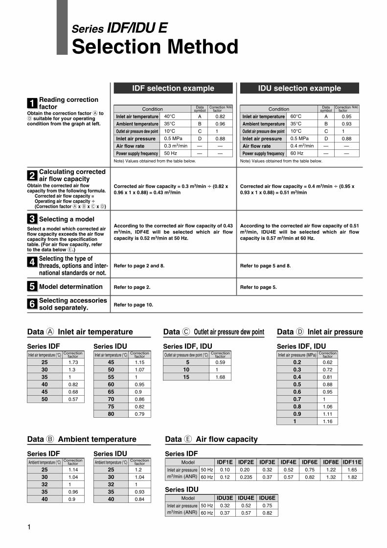
Note) Hexagonal nipple (R threads) is included as an accessory for the thread symbol “F”.
How to Order
Refrigerant HFC134aStandard inlet air temperature
Series IDF�E1E, 2E, 3E, 4E, 6E, 8E, 11E(Inlet air temperature: 35°C, Outlet air pressure dew point: 10°C)
2
IDF 8 10E
SizeSize
0.75 kW
1.5 kW
2.2 kW
3.7 kW
5.5 kW
7.5 kW
11 kW
12346811
Air compressor
Thread type
FN
Note)
Symbol
Nil
Thread
Rc
G
NPT
Voltage
Single phase100 VAC (50 Hz)100 to 110 VAC (60 Hz)
10
Single phase200 VAC (50 Hz)200 to 220 VAC (60 Hz)
20
Symbol VoltageApplicable size
1
�
–
2
�
–
3
�
�
4
�
�
6
�
�
8
�
�
11
�
�
Table of options and available combinations (Size/Option)
1
2
3
4
6
8
11
Symbol Note 1) Nil
Size
Optionspecifications None
�������
A
For coolcompressed
air
�������
C
With anti-corrosivetreatment
�������
H
–
–
–
–
���
K
–
–
–
–
���
L
With heavyduty auto-
drain
–
–
–
����
R
Withcircuit
breaker
–
–
–
����
M
With motoroperatedauto drain
–
–
–
����
T
With terminalblock for run &alarm signal
–
–
–
����
SPower source terminal
block connection(Voltage symbol
10 only)
�������
Nil
ACHKLMRST
Note 1) Enter alphabetically when multiple options are combined.However, the following combinations are not possible.• R and S (Because S function is also included in R.)• S and T (Because S function is also included in T.)
Note 2) Voltage symbol 20 (200 VAC) is the terminal block connection as standard. Option S cannot be chosen. Voltage symbol 10 (100 VAC) is the power cable with plug as standard.
Note 3) Refer to page 8 for further information on options
For medium air pressureCase for auto drain:
Metal case( )For medium air pressure
Case for auto drain:Metal case with level gauge( )
Note 2)
IDF_IDU.qxd 04.8.23 4:33 PM ページ 3
3
Series IDF E
Standard Specifications
Compressor for refrigeration
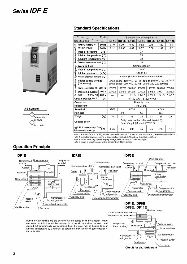
IDF1E IDF2E IDF3E
IDF4E, IDF6EIDF8E, IDF11E
Drain separator
Drain outlet
Compressed air inlet Compressed air outlet
Compressed air outlet
Capillary tube
Compressor for refrigeration
Evaporation thermometer
Reheater
Drain separator
Drain outlet
Compressed air inlet
Compressed air outlet
Pressure switch
Compressor for refrigeration
Drain separator
Drain outlet
Compressed air inlet
Pressure switch
Evaporation thermometerCapillary tube
Humid, hot air coming into the air dryer will be cooled down by a cooler. Water condensed at this time will be removed from the air by a drain separator and drained out automatically. Air separated from the water will be heated to near ambient temperature by a reheater to obtain the dried air, which goes through to the outlet side.
Volume control valve
Pressure switch
Fan motor
Condenser
Cooler
Reheater
Volume control valve
Cooler
Fan motor
Condenser
Cooler
Reheater
Evaporation thermometer
Condenser
Capillary tube Fan motor
0.7
35
32
10
Compressed air
5 to 50
0.15 to 1.0
2 to 40 (Relative humidity of 85% or less)
10 (100 VAC), 5 (200 VAC)
Air-cooled type
HFC134a
Inlet air pressure
Inlet air temperature
Ambient temperature
Outlet air pressure dew point
Working fluid
Inlet air temperature
Inlet air pressure
Ambient temperature (humidity)
Power consumption (W)
Operating current
Circuit breaker Note 4)
Condenser
Refrigerant
Auto drain
Port size
Weight
Coating color
Air flow capacity Note 1)
m3/min (ANR)
Model
Specifications IDF2EIDF1E IDF3E IDF4E IDF6E IDF8E IDF11E50 Hz
60 Hz
(MPa)
(°C)
(°C)
(°C)
(°C)
(MPa)
(°C)
50/60 Hz
100 V
200 V
(A)
(kg)
(kW)
0.10
0.12
0.20
0.235
0.32
0.37
0.52
0.57
0.75
0.82
1.22
1.32
1.65
1.82
180/202
2.4/2.5
—
180/202
2.4/2.5
—
180/202
2.4/2.5
1.2/1.3
180/202
2.4/2.5
1.2/1.3
180/202
2.4/2.5
1.2/1.3
208/236
3.0/3.1
1.5/1.5
385/440
5.7/5.7
3.4/3.0
16
0.75
3/8
17
1.5
18
2.2
1/2
22
3.7
23
5.5
AD48
3/4
27
7.5
28
11
Body panel: White 1 (Munsell 10Y8/0.5)Base: Gray 2 (Munsell 10Y5/0.5)
AD38AD37
Standard inlet air temperature
Note 1) The data for l/min (ANR) is under the conditions of 20°C, 1 atmospheric pressure and relative humidity of 65%..Note 2) Select air dryer according to the selection method (P. 1) and not the rated condition.Note 3) When selecting a power supply voltage, refer to “How to Order” on page 2.Note 4) Install a circuit breaker with a sensitivity of 30 mA or less.
Applicable air compressor output (Guide)In the case of a screw type
Refrigeratedair dryer
Auto drain
JIS Symbol
Operation Principle
Drain outletEvaporationthermometer
Drain separator
Heat exchanger
Capillary tube
Compressed air outlet
Pressure switch
Circuit for air, refrigerant
Compressed air inlet
Volume control valve
Compressor for refrigeration
CondenserFan motor
Rate
d co
nditi
ons
Note
2)
Oper
atin
g ra
nges
Elec
trica
l spe
cifica
tions
Volume control valve
Single phase: 100 VAC (50 Hz), 100 to 110 VAC (60 Hz)Single phase: 200 VAC (50 Hz), 200 to 220 VAC (60 Hz)
Note 3)Power supply voltage(frequency)
(A) 50/60 Hz
IDF_IDU.qxd 04.8.23 4:33 PM ページ 4

4
Dimensions
IDF1E to 3E
IDF4E to IDF11E
Refrigerated Air Dryer Series IDU E
Ventilation direction
Ventilation direction
Evaporation thermometer
Illuminated switch
Drain tube: O.D. ø10
(Thread symbol “N”: 3/8 inch)
Compressed air outlet
Port size
Compressedair inlet
Port size
[200 VAC specification]Power cord outlet (ø17)
Ventilation air inlet
[200 VAC specification]Terminal block
IDF3E-20 only
(820)
A
L K
N M
B
Q
P
E D
FG
H
J
C
[100 VAC specification]Power cord
[100 VAC specification]Power cord
Model
IDF1EIDF2EIDF3EIDF4EIDF6EIDF8EIDF11E
Port size
(mm)
3/8
A
226
B
410
453
455
485
C
413
473
498
568
D69
51
67
31
E101
125
42
F270
232
304
283
355
G 32
138
33
80
H
—
73
230
J
—
31
32
K
38
36
15
L
150
154
240
M21
24
21
80
N330
327
330
275
300
P
240
284
Q
15
13
15270
1/2
3/4
Compressedair inlet
Compressed air outlet
Port size
Port size
[200 VAC specification]Terminal block
[200 VAC specification]Power cord outlet (ø17)
4-ø13
Ventilation air outlet
Ventilation direction
Ventilation direction
Drain tube: O.D. ø10
(Thread symbol “N”: 3/8 inch)
Evaporation thermometer
Illuminated switch
FG
E D
J HMN
A
KL
(820)
C
Q
P
B
IDF_IDU.qxd 04.8.23 4:33 PM ページ 5
5
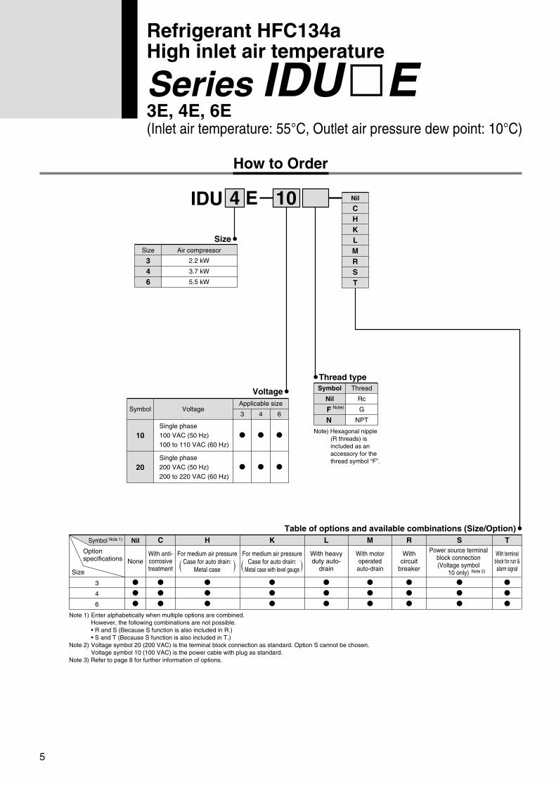
Refrigerant HFC134aHigh inlet air temperature
Series IDU�E3E, 4E, 6E(Inlet air temperature: 55°C, Outlet air pressure dew point: 10°C)
IDU 4 10E
Size
Voltage
Single phase100 VAC (50 Hz)100 to 110 VAC (60 Hz)
10
Single phase200 VAC (50 Hz)200 to 220 VAC (60 Hz)
20
Symbol VoltageApplicable size
3
�
�
4
�
�
6
�
�
Table of options and available combinations (Size/Option)
3
4
6
Symbol Note 1) Nil
Size
Optionspecifications None
���
C
With anti-corrosivetreatment
���
L
With heavyduty auto-
drain
���
R
Withcircuit
breaker
���
T
With terminalblock for run &alarm signal
���
S
���
Nil
CHKLMRST
Size
2.2 kW
3.7 kW
5.5 kW
346
Air compressor
Note 1) Enter alphabetically when multiple options are combined.However, the following combinations are not possible.• R and S (Because S function is also included in R.)• S and T (Because S function is also included in T.)
Note 2) Voltage symbol 20 (200 VAC) is the terminal block connection as standard. Option S cannot be chosen. Voltage symbol 10 (100 VAC) is the power cable with plug as standard.
Note 3) Refer to page 8 for further information of options.
M
With motoroperatedauto-drain
���
H
���
K
���
How to Order
Note) Hexagonal nipple (R threads) is included as an accessory for the thread symbol “F”.
Thread type
FN
Note)
Symbol
Nil
Thread
Rc
G
NPT
Power source terminalblock connection(Voltage symbol
10 only)
For medium air pressureCase for auto drain:
Metal case( )For medium air pressure
Case for auto drain:Metal case with level gauge( )
Note 2)
IDF_IDU.qxd 04.8.23 4:33 PM ページ 6
6
IDU3E, IDU4E, IDU6E
Refrigeratedair dryer
Auto drain
JIS Symbol
Applicable air compressor output (Guide)In the case of a screw type
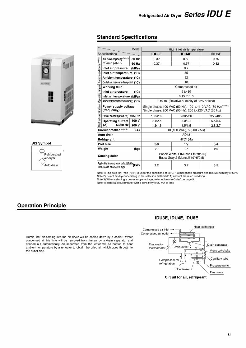
0.7
55
32
10
Compressed air
5 to 80
0.15 to 1.0
2 to 40 (Relative humidity of 85% or less)
10 (100 VAC), 5 (200 VAC)
AD48
HFC134a
IDU4EIDU3E IDU6E50 Hz
60 Hz
(MPa)
(°C)
(°C)
(°C)
(°C)
(MPa)
(°C)
50/60 Hz
100 V
200 V
(A)
(kg)
(kW)
0.32
0.37
0.52
0.57
0.75
0.82
180/202
2.4/2.5
1.2/1.3
208/236
3.0/3.1
1.5/1.5
350/405
5.5/5.6
2.8/2.7
3/8
23
2.2
1/2
27
3.7
3/4
28
5.5
Panel: White 1 (Munsell 10Y8/0.5)Base: Gray 2 (Munsell 10Y5/0.5)
High inlet air temperature
Note 1) The data for l /min (ANR) is under the conditions of 20°C, 1 atmospheric pressure and relative humidity of 65%.Note 2) Select air dryer according to the selection method (P. 1) and not the rated condition.Note 3) When selecting a power supply voltage, refer to “How to Order” on page 5.Note 4) Install a circuit breaker with a sensitivity of 30 mA or less.
Single phase: 100 VAC (50 Hz), 100 to 110 VAC (60 Hz)Single phase: 200 VAC (50 Hz), 200 to 220 VAC (60 Hz)
Drain outletEvaporationthermometer
Drain separator
Heat exchanger
Capillary tube
Compressed air outlet
Pressure switch
Circuit for air, refrigerant
Compressed air inlet
Volume control valve
Compressor for refrigeration
CondenserFan motor
(A) 50/60 Hz
Humid, hot air coming into the air dryer will be cooled down by a cooler. Water condensed at this time will be removed from the air by a drain separator and drained out automatically. Air separated from the water will be heated to near ambient temperature by a reheater to obtain the dried air, which goes through to the outlet side.
Refrigerated Air Dryer Series IDU E
Standard Specifications
Inlet air pressure
Inlet air temperature
Ambient temperature
Outlet air pressure dew point
Working fluid
Inlet air pressure
Inlet air temperature
Ambient temperature (humidity)
Power consumption (W)
Operating current
Circuit breaker Note 4)
Auto drain
Refrigerant
Port size
Weight
Coating color
Power supply voltage(frequency)
Air flow capacity Note 1)
m3/min (ANR)
Model
Specifications
Oper
atin
g ra
nges
Elec
trica
l spe
cifica
tions
Rate
d co
nditi
ons
Note
2)
Note 3)
Operation Principle
IDF_IDU.qxd 04.8.23 4:33 PM ページ 7
7
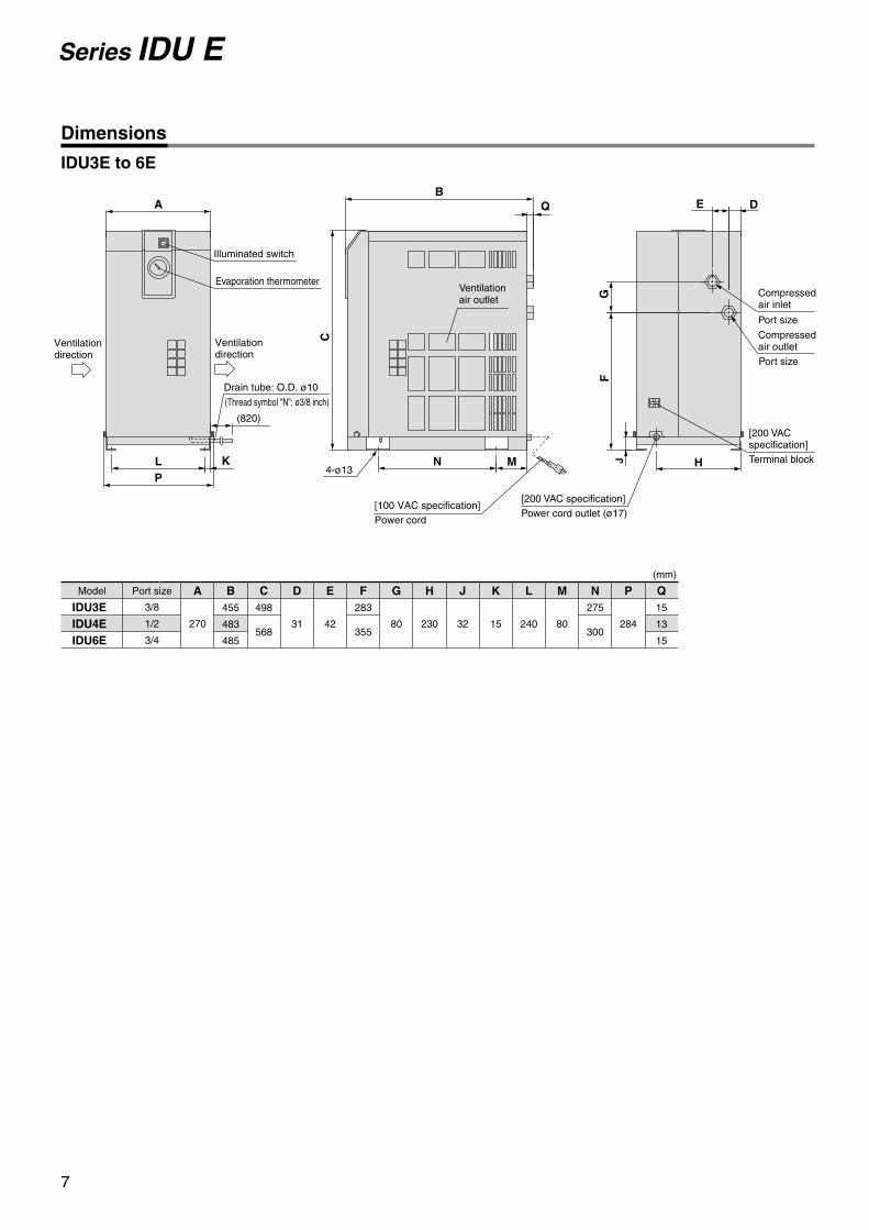
Series IDU E
IDU3E to 6E
[100 VAC specification]Power cord
Model
IDU3EIDU4EIDU6E
Port size
(mm)
3/8
1/2
3/4
A
270
B455
483
485
498
568
283
355
275
300
C D
31
E
42
F G
80 230 32 15 240 80 284
15
13
15
H J K L M N P Q
Compressedair inlet
Compressed air outlet
Port size
Port size
[200 VAC specification]Terminal block
[200 VAC specification]Power cord outlet (ø17)
4-ø13
Ventilation air outlet
Ventilation direction
Ventilation direction
Drain tube: O.D. ø10
(Thread symbol “N”: ø3/8 inch)
Evaporation thermometer
Illuminated switch
FG
E D
J HMN
A
KL
(820)
C
Q
P
B
Dimensions
IDF_IDU.qxd 04.8.23 4:33 PM ページ 8
8
Option Specifications 1Series IDF/IDU E
Refer to pages 2 and 5 for “How to Order” of options.
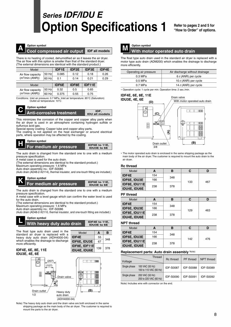
Cool compressed air outputOption symbol
There is no heating of cooled, dehumidified air as it leaves the air dryer. The air flow with this option is smaller than that of the standard dryer. (The external dimensions are identical with the standard product.)
Conditions: Inlet air pressure: 0.7 MPa, Inlet air temperature: 85°C (Saturation) Outlet air temperature: 10°C
Air flow capacity(m3/min (ANR))
Model IDF1E50 Hz
60 Hz
0.085
0.1
IDF2E0.12
0.14
IDF3E0.18
0.21
IDF4E0.26
0.29
Anti-corrosive treatmentOption symbol
This minimizes the corrosion of the copper and copper alloy parts when the air dryer is used in an atmosphere containing hydrogen sulfide or sulfurous acid gas. Special epoxy coating: Copper tube and copper alloy parts. The coating is not applied on the heat exchanger or around electrical parts, where operation may be affected by the coating.
C
For medium air pressureOption symbol
The auto drain is changed from the standard one to one with a medium pressure specification. A metal case is used for the auto drain.(The external dimensions are identical to the standard product.)Maximum operating pressure: 1.6 MPaAuto drain assembly no.: IDF-S0085(Auto drain (AD48-2-X2114), thermal insulator, and one-touch fitting are included.)
H
Air flow capacity(m3/min (ANR))
Model IDF6E 50 Hz
60 Hz
0.32
0.375
IDF8E0.5
0.55
IDF11E0.65
0.75
A IDF all models
IDF,IDU all models
IDF6E to 11E,IDU3E to 6E
For medium air pressureOption symbol
The auto drain is changed from the standard one to one with a medium pressure specification. A metal case with a level gauge which can confirm the water level is used for the auto drain. (The external dimensions are identical to the standard product.)Maximum operating pressure: 1.6 MPaAuto drain assembly no.: IDF-S0086(Auto drain (AD48-2-X2110, thermal insulator, and one-touch fitting are included.)
K IDF6E to 11E,IDU3E to 6E
The float type auto drain used in the standard air dryer is replaced with a motor type auto drain (ADM200) which enables the drainage to discharge more efficiently.
Operating air pressure
0.3 MPa
0.5 MPa
0.7 MPa
Air discharge without drainage
6 l (ANR) per cycle
10 l (ANR) per cycle
14 l (ANR) per cycle
∗ Operation cycle: 1 cycle per min. Operation time: 2 sec./min.
Note) Includes wire with connector on the end.
∗ The motor operated auto drain is enclosed in the same shipping package as the main body of the air dryer. The customer is required to mount the auto drain to the air dryer.
IDU3E, 4E, 6EIDF4E, 6E, 8E, 11E
(D)
(A)
(B)
(C)
Drain outlet
With motor operated auto drainDrain valve
3/8
With motor operated auto drainOption symbolM
IDF4EIDF6E, IDU3EIDF8E, IDU11EIDU4E, IDU6E
Model
154
166
238
A
348
378
B
133
C
467
DRc thread
IDF4EIDF6E, IDU3EIDF8E, IDU11EIDU4E, IDU6E
Model
154
166
238
A
348
378
B
129
C
463
DPF thread
IDF4EIDF6E, IDU3EIDF8E, IDU11EIDU4E, IDU6E
Model
154
166
238
A
348
378
B
142
C
476
DNPT thread
Single phase 100 VAC (50 Hz)100 to 110 VAC (60 Hz)
Single phase 200 VAC (50 Hz)200 to 220 VAC (60 Hz)
Thread
VoltageRc thread
IDF-S0087
IDF-S0090
IDF-S0088
IDF-S0091
IDF-S0089
IDF-S0092
PF thread NPT thread
Replacement parts: Auto drain assembly Note)
Model
55
67
139
IDF4EIDF6E, IDU3EIDF8E, IDF11EIDU4E, IDU6E
A
With heavy duty auto drainOption symbol
The float type auto drain used in the standard air dryer is replaced with a heavy duty auto drain (ADH4000-04) which enables the drainage to discharge more efficiently.
L IDF4E to 11E,IDU3E to 6E
Note) The heavy duty auto drain and the drain valve are both enclosed in the same shipping package as the main body of the air dryer. The customer is required to mount the parts to the air dryer.
348
378
B
IDF4E, 6E, 8E, 11EIDU3E, 4E, 6E
Drain outlet (B)
(A)
(207)
(157)
Drain valve
(ADH4000-04)
Heavy duty auto drain1/2
IDF_IDU.qxd 04.8.23 4:33 PM ページ 9
Option Specifications 2Series IDF/IDU E
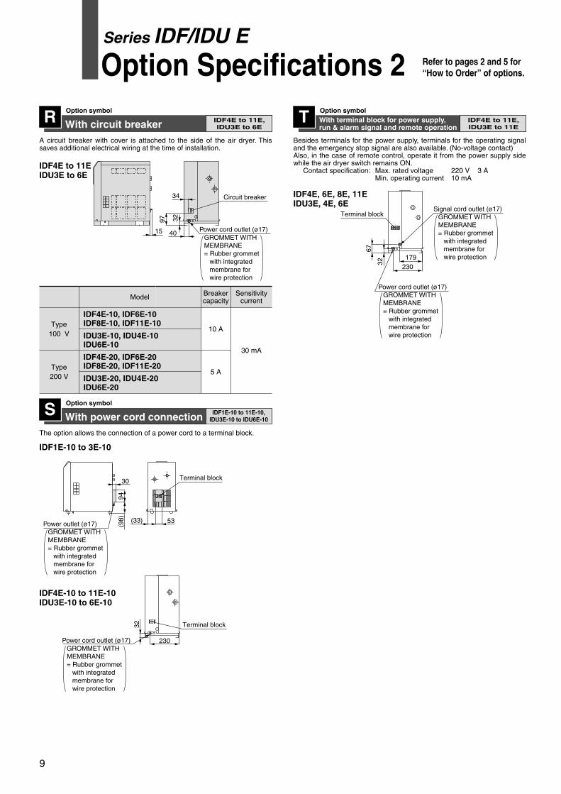
With circuit breakerOption symbolR
A circuit breaker with cover is attached to the side of the air dryer. This saves additional electrical wiring at the time of installation.
With power cord connectionOption symbol
IDF4E to 11E,IDU3E to 6E
SThe option allows the connection of a power cord to a terminal block.
With terminal block for power supply,run & alarm signal and remote operation
Option symbolTBesides terminals for the power supply, terminals for the operating signal and the emergency stop signal are also available. (No-voltage contact)Also, in the case of remote control, operate it from the power supply side while the air dryer switch remains ON. Contact specification: Max. rated voltage 220 V 3 A
Min. operating current 10 mA
IDF4E to 11E,IDU3E to 11E
IDF1E-10 to 11E-10,IDU3E-10 to IDU6E-10
Type100 V
10 A
30 mA
IDF4E-10, IDF6E-10IDF8E-10, IDF11E-10
IDU3E-10, IDU4E-10IDU6E-10
Type200 V
Breakercapacity
5 A
Sensitivitycurrent
IDF4E-20, IDF6E-20IDF8E-20, IDF11E-20
IDU3E-20, IDU4E-20IDU6E-20
IDF4E to 11EIDU3E to 6E
230179
67
32
Terminal block
230
32 Terminal block
(33)
30
(98)
94
Terminal block
32
34
97
15 Power cord outlet (ø17)GROMMET WITH MEMBRANE= Rubber grommet with integrated membrane for wire protection
Circuit breaker
40
IDF1E-10 to 3E-10
IDF4E-10 to 11E-10IDU3E-10 to 6E-10
IDF4E, 6E, 8E, 11EIDU3E, 4E, 6E
53
9
Refer to pages 2 and 5 for “How to Order” of options.
Model
Power cord outlet (ø17)GROMMET WITH MEMBRANE= Rubber grommet with integrated membrane for wire protection
Power outlet (ø17)GROMMET WITH MEMBRANE= Rubber grommet with integrated membrane for wire protection
Power cord outlet (ø17)GROMMET WITH MEMBRANE= Rubber grommet with integrated membrane for wire protection
Signal cord outlet (ø17)GROMMET WITH MEMBRANE= Rubber grommet with integrated membrane for wire protection
IDF_IDU.qxd 04.8.23 4:33 PM ページ 10
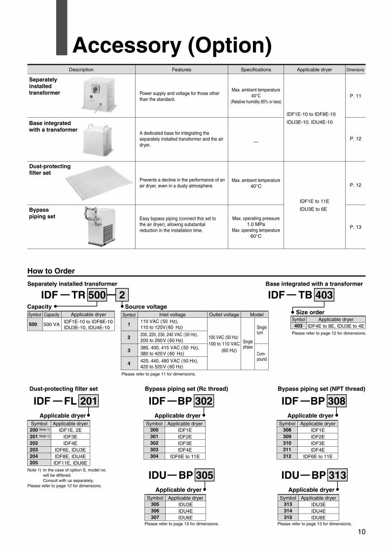
Accessory (Option)
How to Order
IDF TR 500 2Capacity
Separately installed transformer
IDF FL 201Applicable dryer
Dust-protecting filter set
Source voltage
IDF TB
Size order
Base integrated with a transformer
IDF BPApplicable dryer
Bypass piping set (Rc thread)
IDU BP 305Applicable dryer
Symbol
500
Capacity
500 VA
Applicable dryer
IDF1E-10 to IDF8E-10IDU3E-10, IDU4E-10
Symbol
1
2
3
4
Inlet voltage110 VAC (50 Hz), 110 to 120V(60 Hz)
200, 220, 230, 240 VAC (50 Hz),200 to 260V (60 Hz)
380, 400, 415 VAC (50 Hz), 380 to 420V (60 Hz)
420, 440, 480 VAC (50 Hz), 420 to 520V (60 Hz)
Outlet voltage
100 VAC (50 Hz)100 to 110 VAC (60 Hz)
Model
Single phase
Single turn
Com-pound
Symbol403
Applicable dryerIDF4E to 8E, IDU3E to 4E
Please refer to page 12 for dimensions.
Symbol200 Note 1)
201 Note 1)
202203204205
Applicable dryerIDF1E, 2E
IDF3EIDF4E
IDF6E, IDU3EIDF8E, IDU4EIDF11E, IDU6E
Symbol300301302303304
Applicable dryerIDF1EIDF2EIDF3EIDF4E
IDF6E to 11E
Symbol305306307
Applicable dryerIDU3EIDU4EIDU6E
Please refer to page 13 for dimensions.
Please refer to page 11 for dimensions.
Description Features Applicable dryer
IDF1E-10 to IDF8E-10
IDU3E-10, IDU4E-10
IDF1E to 11E
IDU3E to 6E
Power supply and voltage for those other than the standard.
A dedicated base for integrating the separately installed transformer and the air dryer.
Prevents a decline in the performance of an air dryer, even in a dusty atmosphere.
Easy bypass piping (connect this set to the air dryer), allowing substantial reduction in the installation time.
Specifications
Max. ambient temperature40°C
(Relative humidity 85% or less)
—
Max. ambient temperature40°C
Max. operating pressure1.0 MPa
Max. operating temperature60°C
Dimensions
P. 11
P. 12
P. 12
P. 13
Dust-protectingfilter set
Bypass piping set
Base integratedwith a transformer
Separatelyinstalledtransformer
403
Note 1) In the case of option S, model no. will be differed.Consult with us separately.
Please refer to page 12 for dimensions.
302 IDF BPApplicable dryer
Bypass piping set (NPT thread)
IDU BP 313Applicable dryer
Symbol308309310311312
Applicable dryerIDF1EIDF2EIDF3EIDF4E
IDF6E to 11E
Symbol313314315
Applicable dryerIDU3EIDU4EIDU6E
Please refer to page 13 for dimensions.
308
10
IDF_IDU.qxd 04.8.23 4:33 PM ページ 11
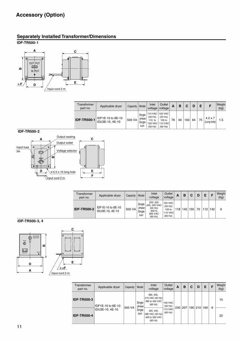
Accessory (Option)
Separately Installed Transformer/Dimensions
Transformerpart no.
Applicable dryer Capacity Model Inletvoltage
Outletvoltage
A B C D E F Weight(kg)
IDF-TR500-1 IDF1E-10 to 8E-10IDU3E-10, 4E-10
500 VA
Single phaseSingleturn
110 VAC(50 Hz)110 to
120 VAC(60 Hz)
100 VAC(50 Hz)100 to
110 VAC(60 Hz)
78 94 100 64 754.2 x 7
(Long hole)1.5
IDF-TR500-3, 4
IDF-TR500-1
IDF-TR500-2
Transformerpart no.
Applicable dryer Capacity ModelInlet
voltageOutlet
voltage A B C D E F Weight(kg)
IDF-TR500-2 IDF1E-10 to 8E-10IDU3E-10, 4E-10
500 VA
Single phaseSingleturn
200, 220230, 240 VAC
(50 Hz)200 to
260 VAC(60 Hz)
100 VAC(50 Hz)100 to
110 VAC(60 Hz)
118 140 150 70 112 142 6
Transformerpart no.
Applicable dryer Capacity ModelInlet
voltageOutlet
voltage A B C D E F Weight(kg)
IDF-TR500-3
IDF1E-10 to 8E-10IDU3E-10, 4E-10
500 VA
Single phaseSingleturn
380, 400, 415 VAC (50 Hz)380 to 420 VAC
(60 Hz)
420, 440,480 VAC (50 Hz)420 to 520 VAC
(60 Hz)
100 VAC(50 Hz)
110 VAC(60 Hz)
230 207 190 210 160 9
15
IDF-TR500-4 22
A
B
D4-F
C
E
Input cord 2 m
A
B
D4-øF
E
Input cord 2 m
C
OUT PUT
IN PUT
VOLUTAGESELECTOR
FUSE
OUT PUT IN PUT
E
C
F
B
D
A
Input cord 2 m
Output outlet
240V
200V
230V
220V
INPUT
Output sealing
Voltage selector
4-5.5 x 10 long hole
Input fuse
5A
11
IDF_IDU.qxd 04.8.23 4:33 PM ページ 12
Accessory (Option)
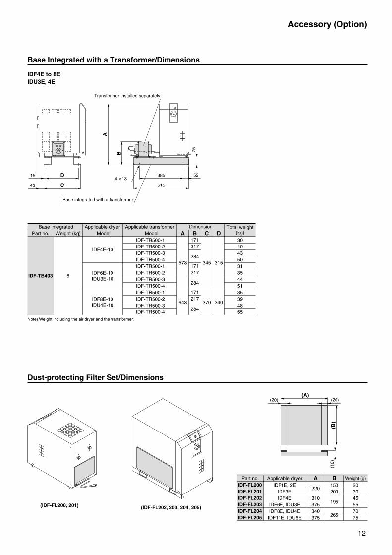
Base Integrated with a Transformer/Dimensions
Dust-protecting Filter Set/Dimensions
(IDF-FL200, 201) (IDF-FL202, 203, 204, 205)
(A)(20)
(B)
(10)
(20)
Base integrated Applicable dryerPart no. Model
Applicable transformerModel
Dimension Total weight(kg)AWeight (kg)
6
IDF4E-10
IDF6E-10IDU3E-10
IDF8E-10IDU4E-10
IDF-TR500-1IDF-TR500-2IDF-TR500-3IDF-TR500-4IDF-TR500-1IDF-TR500-2IDF-TR500-3IDF-TR500-4IDF-TR500-1IDF-TR500-2IDF-TR500-3IDF-TR500-4
573
643
B C
345
370
D
315
340
304043503135445135394855
IDF-TB403
171217
284
171217
284
171217
284
IDF4E to 8EIDU3E, 4E
Part no. Applicable dryer Weight (g)A BIDF1E, 2E
IDF3EIDF4E
IDF6E, IDU3EIDF8E, IDU4EIDF11E, IDU6E
220
310375340375
150200
195
265
203045557075
IDF-FL200IDF-FL201IDF-FL202IDF-FL203IDF-FL204IDF-FL205
B
52
45
15
C
D
75
385
515
A
Base integrated with a transformer
Transformer installed separately
4-ø13
Note) Weight including the air dryer and the transformer.
12
IDF_IDU.qxd 04.8.23 4:33 PM ページ 13
Accessory (Option)
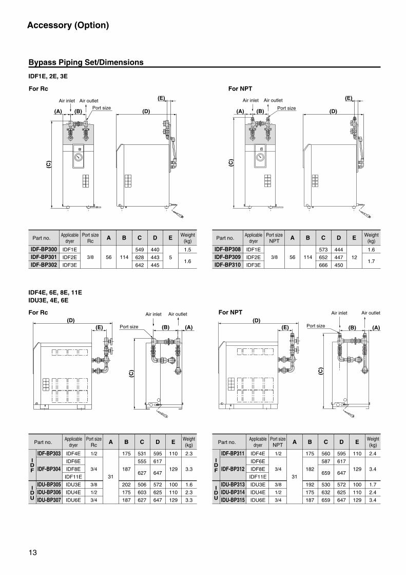
Bypass Piping Set/Dimensions
Part no.
IDF-BP300IDF-BP301IDF-BP302
Applicabledryer
IDF1E
IDF2E
IDF3E
Port sizeRc
A B C
56 114
549
628
642
D
440
443
445
E
5
Weight(kg)
1.5
1.6
IDF1E, 2E, 3E
IDF4E, 6E, 8E, 11EIDU3E, 4E, 6E
Part no.
IDF-BP303
IDF-BP304
IDU-BP305IDU-BP306IDU-BP307
Applicabledryer
IDF4E
IDF6E
IDF8E
IDF11E
IDU3E
IDU4E
IDU6E
Port sizeRc A B C
31
175
187
202
175
187
531
555
627
506
603
627
D
595
617
647
572
625
647
E
110
129
100
110
129
2.3
3.3
1.6
2.3
3.3
1/2
3/4
3/8
1/2
3/4
(C)
(B) (D)
(E)
(D)(A)
Air outletAir inlet
(B)(D)
(A)
(C)
Air outletAir inlet
Port size
Port size
3/8
Part no.
IDF-BP308IDF-BP309IDF-BP310
Applicabledryer
IDF1E
IDF2E
IDF3E
Port sizeNPT
A B C
56 114
573
652
666
D
444
447
450
E
12
1.6
1.73/8
IDF
IDU
Part no.
IDF-BP311
IDF-BP312
IDU-BP313IDU-BP314IDU-BP315
Applicabledryer
IDF4E
IDF6E
IDF8E
IDF11E
IDU3E
IDU4E
IDU6E
Port sizeNPT A B C
31
175
182
192
175
187
560
587
659
530
632
659
D
595
617
647
572
625
647
E
110
129
100
110
129
2.4
3.4
1.7
2.4
3.4
1/2
3/4
3/8
1/2
3/4
IDF
IDU
(C)
(B)(D)
(A)
For NPT Air outletAir inlet
(C)
(B)(A)Port size
Air outlet
For NPTFor Rc
Air inlet
Port size
13
For Rc
(E)
(E)(E)
Weight(kg)
Weight(kg)
Weight(kg)
IDF_IDU.qxd 04.8.23 4:33 PM ページ 14
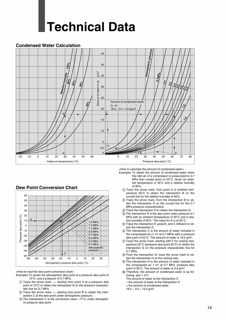
Technical Data
<How to calculate the amount of condensed water>Example) To obtain the amount of condensed water when
the inlet air of a compressor is pressurized to 0.7 MPa then cooled down to 25°C. Given an ambi-ent temperature of 30°C and a relative humidity of 60%.
� Trace the arrow mark, from point A of ambient tem-perature 30°C to obtain the intersection B on the curved line for the relative humidity of 60%.
� Trace the arrow mark, from the intersection B to ob-tain the intersection D on the curved line for the 0.7 MPa pressure characterisitics.
� Trace the intersection D to obtain the intersection E.� The intersection E is the dew point under pressure 0.7
MPa with an ambient temperature of 30°C and a rela-tive humidity of 60%. The value for E is at 62°C.
� Trace the intersection E upward, and C leftward to ob-tain the intersection D.
� The intersection C is the amount of water included in the compressed air (1 m3 at 0.7 MPa) with a pressure dew point of 62°C. The amount of water is 18.2 g/m3.
� Trace the arrow mark, starting with F for cooling tem-perature 25°C (pressure dew point 25°C) to obtain the intersection G on the pressure characteristic line for 0.7 MPa.
� From the intersection G, trace the arrow mark to ob-tain the intersection H on the vertical axis.
The intersection H is the amount of water included in the compressed air 1 m3 at 0.7 MPa, pressure dew point of 25°C. The amount of water is 3.0 g/m3.
Therefore, the amount of condensed water is as fol-lowing. (per 1 m3)The amount of water at the intersection C – the amount of water at the intersection H = the amount of condensed water18.2 – 3.0 = 15.2 g/m3
<How to read the dew point conversion chart>Example) To obrain the atmospheric dew point at a pressure dew point of
10°C, and a pressure of 0.7 MPa.� Trace the arrow mark �, starting from point A at a pressure dew
point of 10°C to obtain the intersection B on the pressure character-istic line for 0.7 MPa.
� Trace the arrow mark �, starting from point B to obtain the inter-section C at the dew point under atmospheric pressure.
� The intersection C is the conversion value –17°C under atmosphe-ric pressure dew point.
Dew Point Conversion Chart
Condensed Water Calculation
Intake air temperature (°C) Pressure dew point (°C)
-20 -10 0 10 20 30 40 50 60 0 10 20 30 40 50 60 70 80
45
40
35
30
25
20
15
10
5
0
3.0
Amount of condensed waterC—H18.2 - 3.0 = 15.2g/m3
E
H
Am
ount
of w
ater
in a
ir
g/m
3
0.2
0.3
0.4
0.5
0.6
0.7
0.8
Rel
ativ
e hu
mid
ity
100
%80
%
60%
40%
20%
1.0
1.5
0.1M
Pa
Atmospheric pressure dew point (°C)
Pre
ssur
e de
w p
oint
(°C
)
0
10
20
30
40
50
60
-60 -50-60
-50
-40 -30
-40
-30
-20
-10
-20 -10 0 10 20 30
A
B C
G
F
D
A
C
B
14
Atm
osp
her
ic p
ress
ure
1.5 MPa1.3 MPa1.1 MPa0.9 MPa0.7 MPa0.5 MPa0.3 MPa0.1 MPaAtmosphericpressure
IDF_IDU.qxd 04.8.23 4:33 PM ページ 15