Embed Size (px)
Citation preview
7/27/2019 rectificador- electronica.docx
http://slidepdf.com/reader/full/rectificador-electronicadocx 1/13
INSTITUTO POLITÉCNICO NACIONAL
ESCUELA SUPERIOR DE CÓMPUTO
ANALOG ELECTRONICS
PRACTICE #2
RECTIFIERS
PROFESSOR: JOSE ALFREDO MARTINEZ GUERRERO
GROUP: 2CV5
AURIOLES DELGADILLO, MAURICIO JOEL
JIMENEZ SANDOVAL, EDUARDO
SCHOOL CYCLE2013-2014/2
FEBRUARY 27 OF 2014
7/27/2019 rectificador- electronica.docx
http://slidepdf.com/reader/full/rectificador-electronicadocx 2/13
OBJECTIVES
The objectives of this practice are:
Analyze how rectifiers work with different diodes.
Analyze the behavior of different rectifiers with integration filter. Make an interpretation of the obtained values and the theoretical ones.
MATERIAL AND EQUIPMENT
MATERIAL1 Proto board4 1N4003 diodes112V @ 1A Transformer with central derivation1 100Ω @ 10W Resistance
1 22Ω @ 25W Resistance 1 470µF @ 50V Electrolytic Capacitor1 2200µF @ 50V Electrolytic Capacitor
EQUIPMENT1 Digital multimeters1 General purpose Oscilloscope2 BNC-Alligator cables for oscilloscope6 alligator-alligator cables
INTRODUCTION
Most of the electronic devices, televisions, stereo equipment and computers needa DC voltage to run continuously.
As voltage lines are alternate, the first thing to do is to convert the alternatingvoltage into DC voltage.The circuits that allow current to flow in one direction are called rectifiers.Now, the analysis of diodes should be extended to include the variable functions intime, such as the sine wave shape.
7/27/2019 rectificador- electronica.docx
http://slidepdf.com/reader/full/rectificador-electronicadocx 3/13
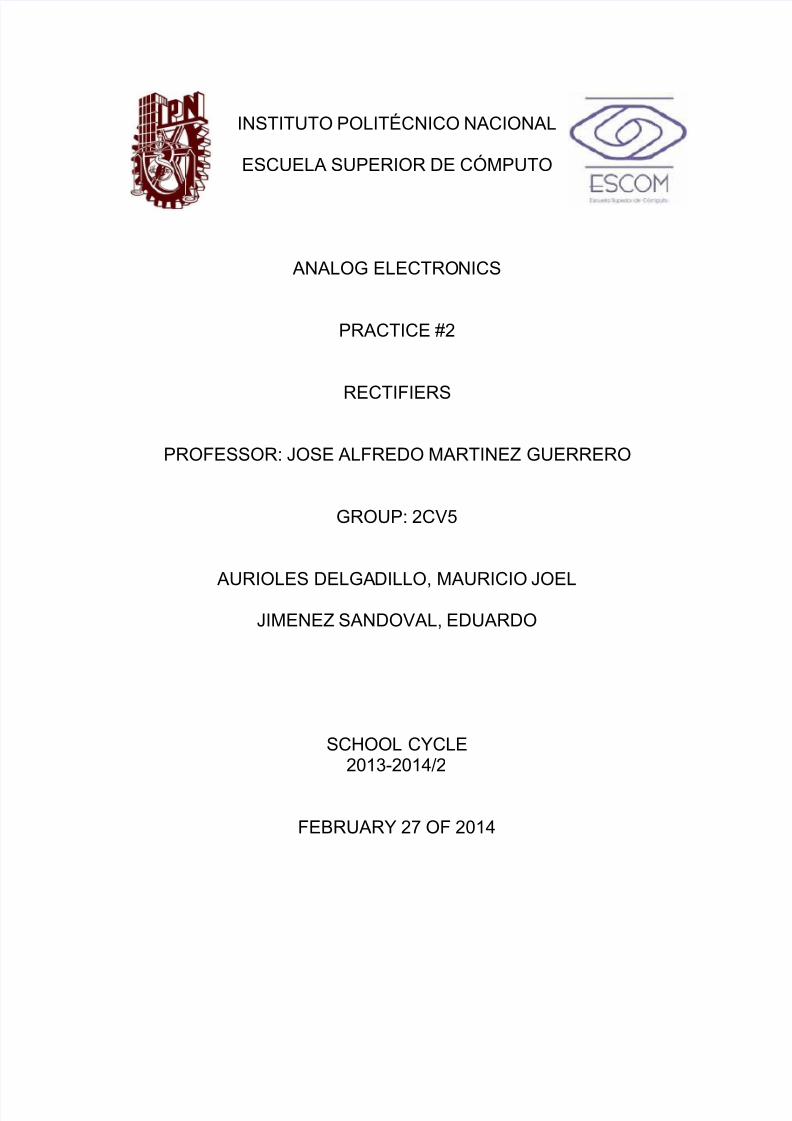
HALF-WAVE RECTIFIER
Half-wave rectifier is a circuit that eliminates half of thereceived signal at the entrance, depending on how is
polarized the diode: If the polarization is direct, eliminatethe negative part of the signal, and if the polarization isreverse, remove the positive part.
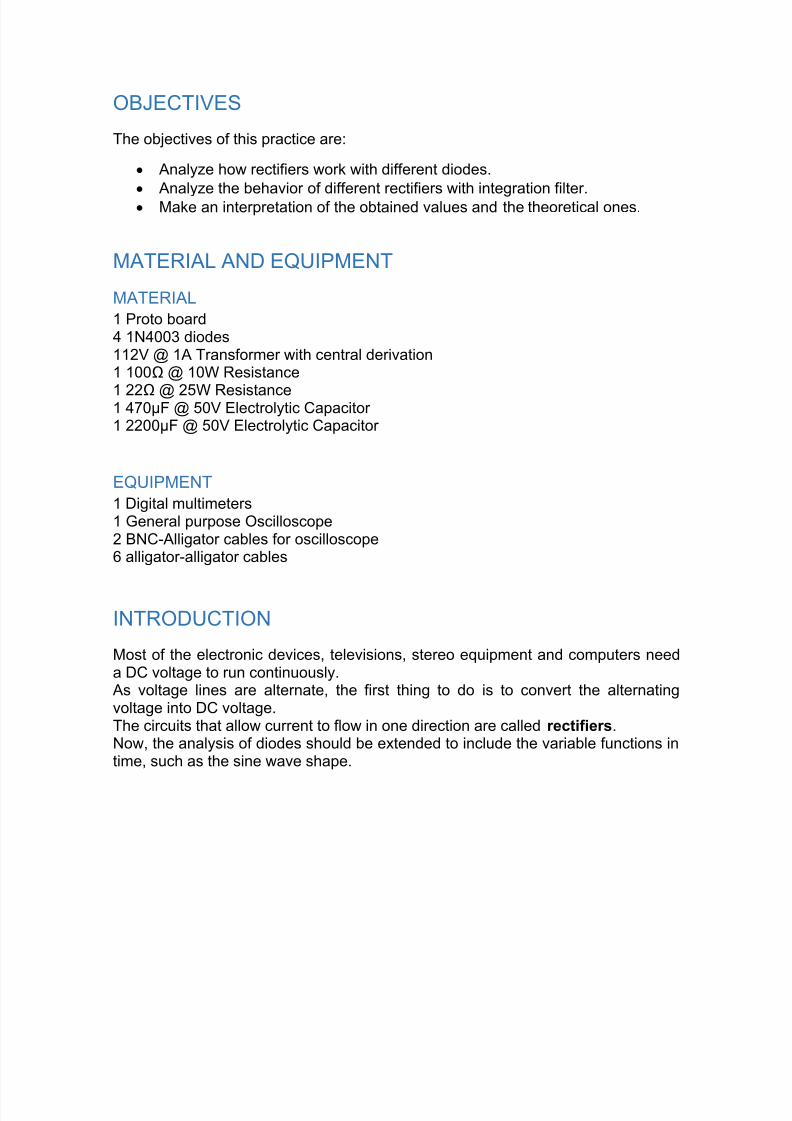
HALF-WAVE RECTIFIER WITH INTEGRATIONFILTER
A RC circuit serves as a filter to make the alternating voltage become direct almostlike a battery, this is thanks to the small oscillations the output voltage has, whichare practically nil.The first part of the circuit consists of an AC voltage source, followed by a diodethat on this occasion will be ideal (simply to facilitate the understanding of theoperation) and finally the RC filter.The circuit works in the following way:1. enter the AC signal to the circuit, which is
rectified with diode. (Only allows passing a semi-cycle of the signal, which in this case is thepositive semi-cycle)
2. at the moment coming voltage diode capacitorbegins to charge and the voltage drop is receivedin the resistance.
3. to understand what is happening and howcalculate the filter.
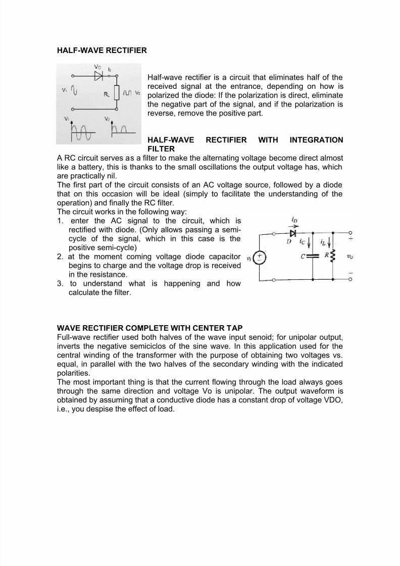
WAVE RECTIFIER COMPLETE WITH CENTER TAPFull-wave rectifier used both halves of the wave input senoid; for unipolar output,inverts the negative semiciclos of the sine wave. In this application used for thecentral winding of the transformer with the purpose of obtaining two voltages vs.equal, in parallel with the two halves of the secondary winding with the indicatedpolarities.The most important thing is that the current flowing through the load always goesthrough the same direction and voltage Vo is unipolar. The output waveform isobtained by assuming that a conductive diode has a constant drop of voltage VDO,i.e., you despise the effect of load.
7/27/2019 rectificador- electronica.docx
http://slidepdf.com/reader/full/rectificador-electronicadocx 4/13
FULL WAVE BRIDGE RECTIFIERIt is a rectifier full wave in which, unlike the previous, only necessary transformer ifthe output voltage should be a value other than the input voltage.In order to facilitate the explanation of the operation of this circuit, we are going tocall D-1 diode located above and D-2, D-3 and D-4 the following in descendingorder.
o During the half cycle in which the upper point of the secondary of thetransformer is positive with respect to the lower secondary said, the currentflows through the following way:
Top point of the secondary - > diode D-1 - > (+) R(-) load resistance - > diode D-4 -
> bottom point of the secondary.o In the next half-cycle, when the upper point of the secondary is negative and
the positive bottom it will do this by:Lowest point of the secondary - > diode D-2 - > (+) R (-) load resistance - > diodeD-3 - > upper point of the secondary.In this case, we see how current it circulates by charging, in the same sense, thetwo semiciclos, which both take advantage and gets a ground current more uniformthan in the case of the half-wave rectifier, where during a half-cycle the current flowis interrupted by the load.
In both types of full-wave rectifiers, the rectified output current waveform, is likely tobe a continuous pulse current, but with a frequency of double pulse of current ACpower.
7/27/2019 rectificador- electronica.docx
http://slidepdf.com/reader/full/rectificador-electronicadocx 5/13
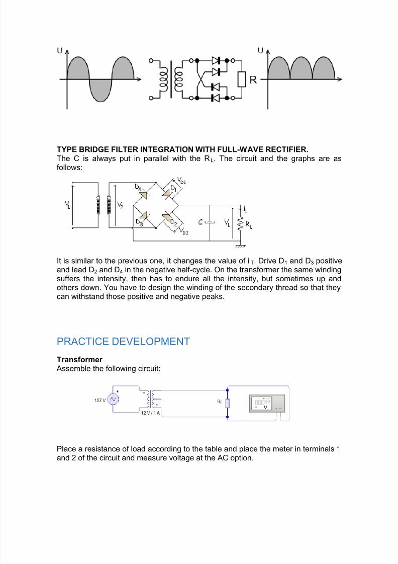
TYPE BRIDGE FILTER INTEGRATION WITH FULL-WAVE RECTIFIER.The C is always put in parallel with the RL. The circuit and the graphs are asfollows:
It is similar to the previous one, it changes the value of i T. Drive D1 and D3 positiveand lead D2 and D4 in the negative half-cycle. On the transformer the same windingsuffers the intensity, then has to endure all the intensity, but sometimes up andothers down. You have to design the winding of the secondary thread so that they
can withstand those positive and negative peaks.
PRACTICE DEVELOPMENT
Transformer Assemble the following circuit:
Place a resistance of load according to the table and place the meter in terminals 1and 2 of the circuit and measure voltage at the AC option.
7/27/2019 rectificador- electronica.docx
http://slidepdf.com/reader/full/rectificador-electronicadocx 6/13
100Ω 15.10v22 Ω 14.35v
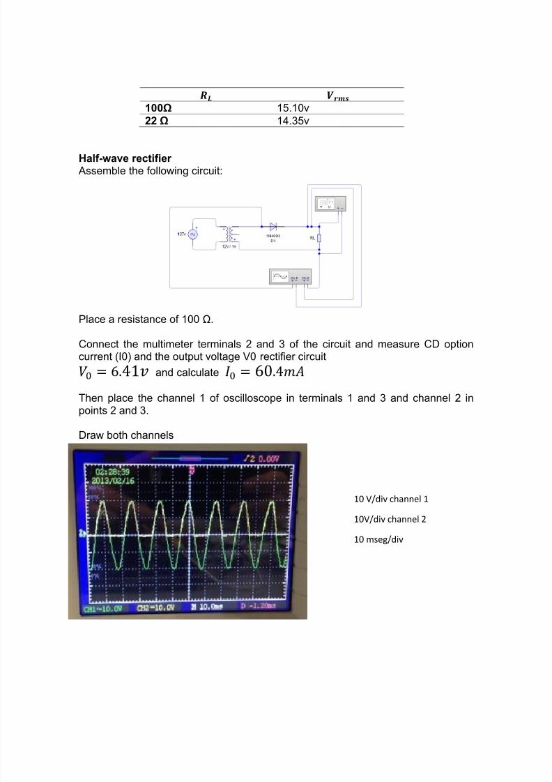
Half-wave rectifier Assemble the following circuit:
Place a resistance of 100 Ω.
Connect the multimeter terminals 2 and 3 of the circuit and measure CD optioncurrent (I0) and the output voltage V0 rectifier circuit
and calculate
Then place the channel 1 of oscilloscope in terminals 1 and 3 and channel 2 in
points 2 and 3.
Draw both channels
10 V/div channel 1
10V/div channel 2
10 mseg/div
7/27/2019 rectificador- electronica.docx
http://slidepdf.com/reader/full/rectificador-electronicadocx 7/13
Get the voltage peak of the channel 1 signal transformer
Get the peak voltage less channel 2 diode voltage
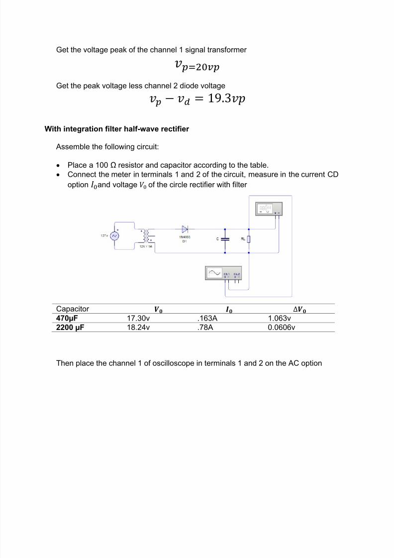
With integration filter half-wave rectifier
Assemble the following circuit:
Place a 100 Ω resistor and capacitor according to the table. Connect the meter in terminals 1 and 2 of the circuit, measure in the current CD
option and voltage of the circle rectifier with filter
Capacitor 470µF 17.30v .163A 1.063v2200 µF 18.24v .78A 0.0606v
Then place the channel 1 of oscilloscope in terminals 1 and 2 on the AC option
7/27/2019 rectificador- electronica.docx
http://slidepdf.com/reader/full/rectificador-electronicadocx 8/13
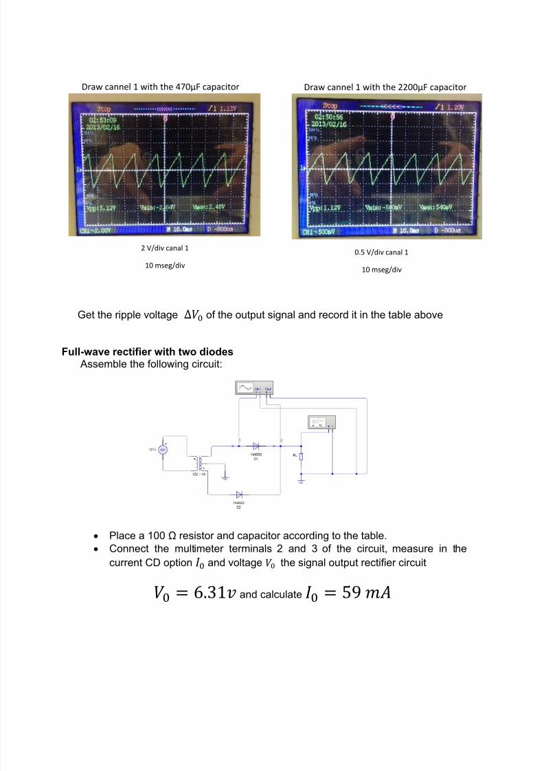
Get the ripple voltage of the output signal and record it in the table above
Full-wave rectifier with two diodes Assemble the following circuit:
Place a 100 Ω resistor and capacitor according to the table. Connect the multimeter terminals 2 and 3 of the circuit, measure in thecurrent CD option and voltage the signal output rectifier circuit
and calculate
Draw cannel 1 with the 470µF capacitor Draw cannel 1 with the 2200µF capacitor
2 V/div canal 1
10 mseg/div
0.5 V/div canal 1
10 mseg/div
7/27/2019 rectificador- electronica.docx
http://slidepdf.com/reader/full/rectificador-electronicadocx 9/13
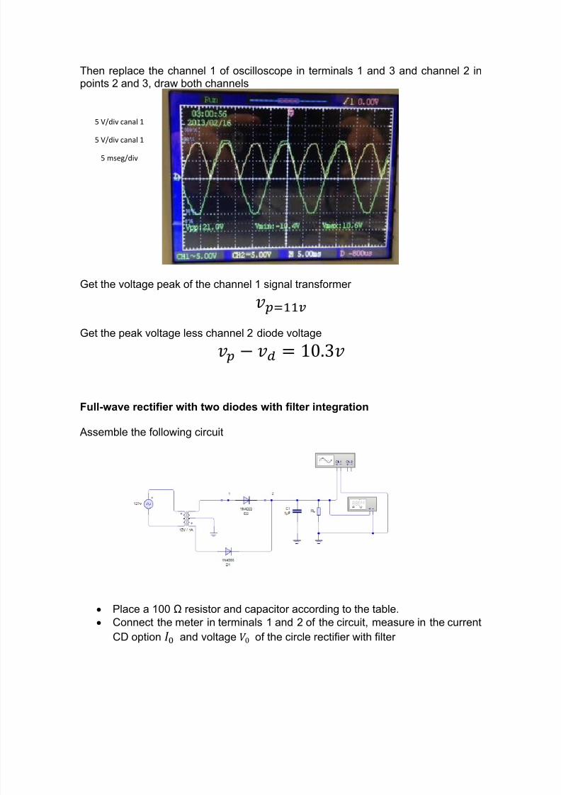
Then replace the channel 1 of oscilloscope in terminals 1 and 3 and channel 2 inpoints 2 and 3, draw both channels
Get the voltage peak of the channel 1 signal transformer
Get the peak voltage less channel 2 diode voltage
Full-wave rectifier with two diodes with filter integration
Assemble the following circuit
Place a 100 Ω resistor and capacitor according to the table. Connect the meter in terminals 1 and 2 of the circuit, measure in the current
CD option and voltage of the circle rectifier with filter
5 V/div canal 1
5 V/div canal 1
5 mseg/div
7/27/2019 rectificador- electronica.docx
http://slidepdf.com/reader/full/rectificador-electronicadocx 10/13
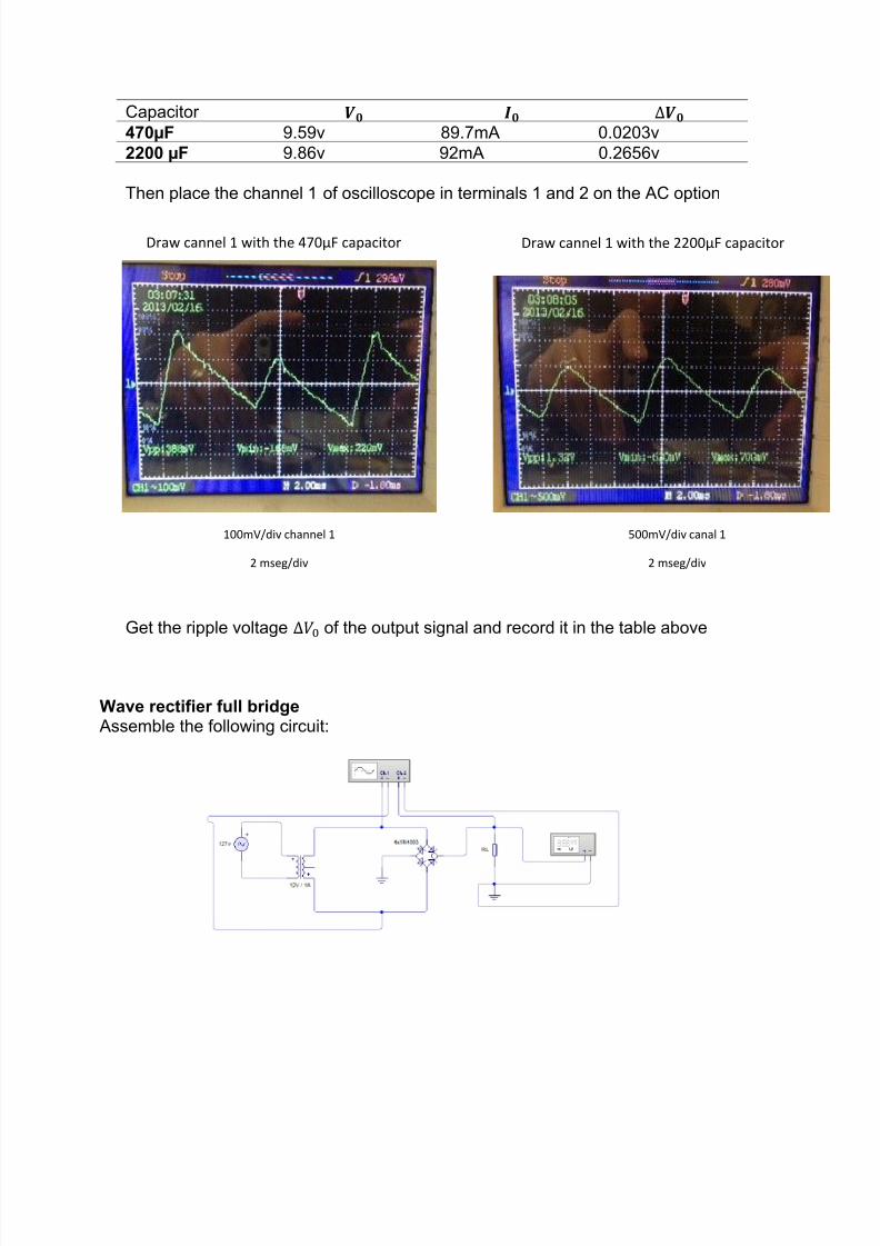
Capacitor 470µF 9.59v 89.7mA 0.0203v2200 µF 9.86v 92mA 0.2656v
Then place the channel 1 of oscilloscope in terminals 1 and 2 on the AC option
Get the ripple voltage of the output signal and record it in the table above
Wave rectifier full bridge Assemble the following circuit:
Draw cannel 1 with the 470µF capacitor Draw cannel 1 with the 2200µF capacitor
100mV/div channel 1
2 mseg/div
500mV/div canal 1
2 mseg/div
7/27/2019 rectificador- electronica.docx
http://slidepdf.com/reader/full/rectificador-electronicadocx 11/13
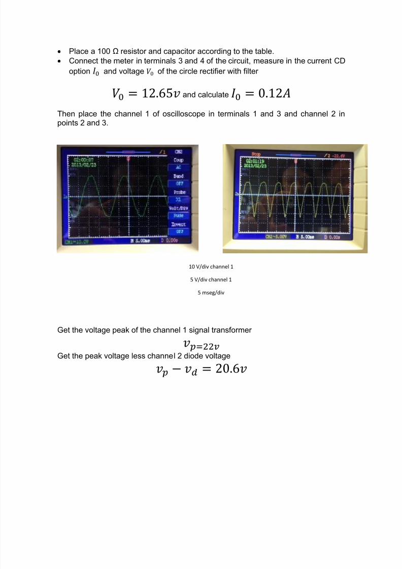
Place a 100 Ω resistor and capacitor according to the table. Connect the meter in terminals 3 and 4 of the circuit, measure in the current CD
option and voltage of the circle rectifier with filter
and calculate
Then place the channel 1 of oscilloscope in terminals 1 and 3 and channel 2 inpoints 2 and 3.
Get the voltage peak of the channel 1 signal transformer
Get the peak voltage less channel 2 diode voltage
10 V/div channel 1
5 V/div channel 1
5 mseg/div
7/27/2019 rectificador- electronica.docx
http://slidepdf.com/reader/full/rectificador-electronicadocx 12/13
Full-wave rectifier type bridge integration filter Assemble the following circuit:
Place a 100 Ω resistor and capacitor according to the table.
Connect the meter in terminals 1 and 2 of the circuit, measure in the currentCD option and voltage of the circle rectifier with filter
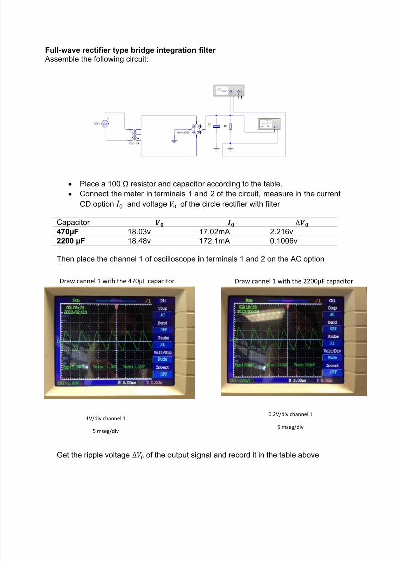
Capacitor 470µF 18.03v 17.02mA 2.216v2200 µF 18.48v 172.1mA 0.1006v
Then place the channel 1 of oscilloscope in terminals 1 and 2 on the AC option
Get the ripple voltage of the output signal and record it in the table above
Draw cannel 1 with the 470µF capacitor Draw cannel 1 with the 2200µF capacitor
1V/div channel 1
5 mseg/div
0.2V/div channel 1
5 mseg/div
7/27/2019 rectificador- electronica.docx
http://slidepdf.com/reader/full/rectificador-electronicadocx 13/13
CALCULATIONS
QUESTIONNAIRE
CONCLUSIONS
Eduardo JimenezEn esta práctica, observamos cada una de las gráficas de los distintos diodosrectificadores y su voltaje de rizo, con respecto a las gráficas vimos como era suvoltaje de entrada y al pasar por el rectificador, su grafica en el voltaje de salidacambiaba.
Mauricio AuriolesEn la segunda práctica, usamos los diferentes tipos de rectificadores. Armamosdiferentes circuitos para reconocer las gráficas que nos daba en el osciloscopio.
Es importante aprender cada una de sus graficas porque la mayoría nos dabanuna de entrada y una de salida, por lo que conectamos los circuitos en los doscanales del osciloscopio. Medimos voltajes en las diferentes resistencias de cargay corrientes de salida de cada uno de los circuitos; y finalmente, calculamos losvoltajes de rizo utilizando los valores obtenidos.