Embed Size (px)
Citation preview

RealScan 7883Installation and OwnerGuide
12623
497-0424789Release DOctober 7, 2002
Information ProductsRSD-Atlanta

NCR RealScan 7883 Installation and Owner Guide
10/07 497-0424789 Release D2 of 74
The program products described in this book are licensed products of NCRCorporation. It is the policy of NCR to improve products as new technology,components, software, and firmware become available. Therefore, NCR reserves theright to change specifications without prior notice. All features, functions, andoperations described herein may not be marketed by NCR in all parts of the world.Therefore, before using this document, consult your NCR representative or NCR officefor information that is applicable and current.
ContentsContents..................................................................................................................................2Revision Record .....................................................................................................................2Obtaining Additional Information .......................................................................................3Obtaining Technical Assistance ............................................................................................3NCR RealScan 7883 Mountings ............................................................................................4Installation Instructions.........................................................................................................5Step 1 - Installing Power Supply and Interface Cables .......................................................6Step 2 - Setting Program Parameters and Verifying Host Connection............................10Step 3 - Setting RealScan 7883 Scan Zone...........................................................................18Step 4 - Mounting the RealScan 7883..................................................................................21Operating the Scanner .........................................................................................................25Cleaning the Scanner ...........................................................................................................26Correcting Scanner Problems..............................................................................................27Interface Information...........................................................................................................29NCR RealScan 7883 Specifications......................................................................................31NCR RealScan 7883, METTLER TOLEDO® Scale, & Sensormatic ScanMaxTMHS..........34Programming Worksheets...................................................................................................45ASCII Code Chart ................................................................................................................53Regulatory Information .......................................................................................................54Laser Safety ..........................................................................................................................57Programming Tags...............................................................................................................59
Revision Record
Date Pages Issue Remarks02/26/02 All A First printing.07/18/02 All B Updated to match latest units.09/09/02 All C Added USB Interface
Updated to match latest units.10/07/02 59-72 D Added Programming Tags

NCR RealScan 7883 Installation and Owner Guide
497-0424789 Release D 10/07 3 of 74
Obtaining Additional InformationOther Information Products
Order Number TitleB005-0000-1436 NCR RealScan 7883 User GuideB005-0000-1437 NCR RealScan 7883 Repair GuideBST0-2121-74 NCR Scanner Programming TagsBD20-1074-A NCR Scanner/Scale Interface Programmer’s Guide
How To Obtain Information ProductsWeb Sites• http://inforetail.AtlantaGA.NCR.
COM (NCR only)• http://www.info.NCR.COM
(Anyone)
Online Order• Connect System (NCR only)
Phone Order• 800-543-2010 (US area)• 622-3727 (VOICEplus)• 44-181-242-5350 (International)
Fax Order• 937-445-6245 (US area)• 44 (0) 20 8 242 5355 (International)
E-Mail• [email protected]
(US area)• [email protected].
COM (International)
Mail Order• NCR Corporation IPP-Dayton
1529 Brown St.IPP EMD-2Dayton, OH 45479USA
• NCR Corporation915 High RoadNorth FinchleyLondon N12 0HN United Kingdom
Obtaining Technical Assistance
Technical assistance is available as follows.
• Technical assistance in the United States: 1-800-262-7782• Technical assistance in other countries: call your local NCR office• To order parts: 1-800-438-7830
Note: If you find any defective parts during installation of a new scanner, contact theCustomer Satisfaction Hotline at one of the following.
• In the United States, call: 1-800-528-8658 (USA)• In all other countries call: your local NCR office• E-mail: [email protected]
NCR RealScan 7883 Installation and Owner Guide
10/07 497-0424789 Release D4 of 74
NCR RealScan 7883 Mountings
RealScan 7883 ScannerThe NCR RealScan 7883 Scanner is a small, compact laser scanner with many of thesame features as the larger scanners. It can be mounted horizontally in a checkstand orvertically above the checkstand. Various mounts are available for the RealScan 7883.
Scanner
Vertical Mount
Top Plate(Horizontal Mount)
Horizontal MountFlat Plate Adapter
Horizontal Mount7820 Adapter
Horizontal Mount7852 Adapter
Vertical MountWith Top Plate
18681

NCR RealScan 7883 Installation and Owner Guide
497-0424789 Release D 10/07 5 of 74
Installation Instructions
When installing a RealScan 7883, it is recommended that you first mount the PowerSupply and run all the cables. After connecting the unit to the host terminal, make anynecessary programming changes and scan some good tags to verify that the scanner iscommunicating with the host terminal. After verifying that everything is workingcorrectly, mount the unit in the checkstand. If the RealScan 7883 does not workproperly, refer to the problem correcting section in this document: Correcting ScannerProblems.
The following flowchart shows the sequence of installation steps. Detailed descriptionsof each step follow.
19762
Installing Power Supply andInterface Cables
Step 1
Step 2
Step 3
Step 4
Setting Program Parameters andVerifying Host Connection
Setting the Scan Zone
Mounting the RealScan 7883
NCR RealScan 7883 Installation and Owner Guide
10/07 497-0424789 Release D6 of 74
Step 1 - Installing Power Supplyand Interface Cables
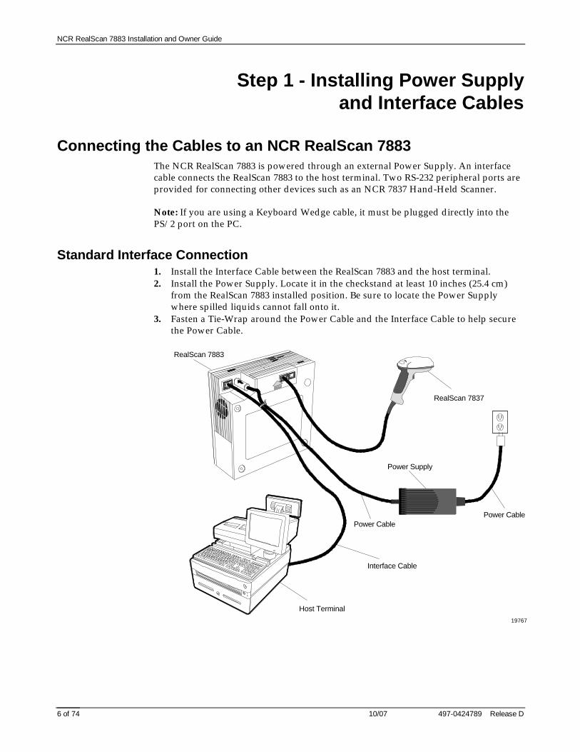
Connecting the Cables to an NCR RealScan 7883The NCR RealScan 7883 is powered through an external Power Supply. An interfacecable connects the RealScan 7883 to the host terminal. Two RS-232 peripheral ports areprovided for connecting other devices such as an NCR 7837 Hand-Held Scanner.
Note: If you are using a Keyboard Wedge cable, it must be plugged directly into thePS/2 port on the PC.
Standard Interface Connection1. Install the Interface Cable between the RealScan 7883 and the host terminal.2. Install the Power Supply. Locate it in the checkstand at least 10 inches (25.4 cm)
from the RealScan 7883 installed position. Be sure to locate the Power Supplywhere spilled liquids cannot fall onto it.
3. Fasten a Tie-Wrap around the Power Cable and the Interface Cable to help securethe Power Cable.
RealScan 7883D
C
Interface Cable
Host Terminal
19767
RealScan 7837
Power Supply
Power CablePower Cable

NCR RealScan 7883 Installation and Owner Guide
497-0424789 Release D 10/07 7 of 74
USB Interface Connection
Connecting a RealScan 7883 Scanner to a USB port on a host terminal requires a specialcable. One end of the Dongle Adapter Cable connects to the host terminal. The otherend has an Interface Box that contains a printed circuit board with all the necessarycircuitry. The host terminal supplies power for this circuitry. An Interface cableconnects the scanner to this box. A Power Supply connected to the scanner is requiredfor all configurations.
19406
RealScan 7883
DC
Power Cord
Dongle Adapter Cable
Host Terminal
RealScan 7837
Power Supply
Interface Cable
Interface Box
Power Cable
NCR RealScan 7883 Installation and Owner Guide
10/07 497-0424789 Release D8 of 74
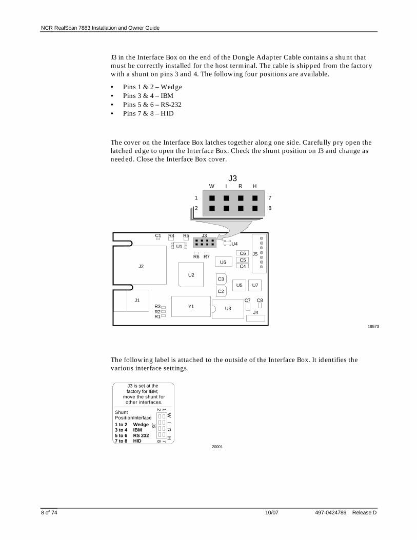
J3 in the Interface Box on the end of the Dongle Adapter Cable contains a shunt thatmust be correctly installed for the host terminal. The cable is shipped from the factorywith a shunt on pins 3 and 4. The following four positions are available.
• Pins 1 & 2 – Wedge• Pins 3 & 4 – IBM• Pins 5 & 6 – RS-232• Pins 7 & 8 – HID
The cover on the Interface Box latches together along one side. Carefully pry open thelatched edge to open the Interface Box. Check the shunt position on J3 and change asneeded. Close the Interface Box cover.
19573
J1
J2
J3
J4
J5
R1R2R3
R4 R5
R6 R7
C1
C2
C3
C4C5C6
C7 C8
U1
U2
U3
U4
U5
U6
U7
Y1
1
2
7
8
W I R HJ3
The following label is attached to the outside of the Interface Box. It identifies thevarious interface settings.
J3 is set at thefactory for IBM;
move the shunt forother interfaces.
ShuntPositionInterface1 to 23 to 45 to 67 to 8
WedgeIBMRS 232HID
1278
W I R
H
J3
20001

NCR RealScan 7883 Installation and Owner Guide
497-0424789 Release D 10/07 9 of 74
Auxiliary RS-232 PortThe Auxiliary RS-232 Port provides a connection for an RS-232 device such as anNCR RealScan 7837 Hand-Held Scanner. The following table gives wiring informationabout the connector.
Auxiliary RS-232 PortPin Number Signal Name1 +5 Vdc2 NC3 GND4 TXD5 RXD6 + 12 Vdc7 CTS8 RTS9 Frame10 Frame
NCR RealScan 7835/7836
• 1416-C313-0040 – Interface Cable• 1416-C397-0010 – Extension Cable
NCR RealScan 7837
• 1416-C445-0025 – Interface Cable• 1416-C397-0010 – Extension Cable
The RealScan 7883 auxiliary RS-232 port hardware is limited to the following fixedparameters.
Baud Rate 9600Parity OddStop Bits 1Number of Data Bits 7Hardware Handshaking NoneTerminator Character CRLFUPC-A Prefix Character dUPC-E Prefix Character dEAN 8 Prefix Character dEAN 13 Prefix Character dCode 128 Prefix Character fCode 39 Prefix Character aInterleaved 2 of 5 Prefix Character b
Note: ASCII data cannot be sent from the auxiliary RS-232 port when the 7883 is set forOCIA Short format. In this case, the RealScan 7883 generates an error beep.
When a RealScan 7836 is attached to a RealScan 7883, the 7836 requires the followingprogramming.
• Reset to serial (default values) – Label ZA• Enable code ID (default values) – Label FB
NCR RealScan 7883 Installation and Owner Guide
10/07 497-0424789 Release D10 of 74
Step 2 - Setting ProgramParameters and Verifying Host
Connection
Now you need to turn on the NCR RealScan 7883. After making any necessaryprogram changes, scan a few tags to verify that the RealScan 7883 is communicatingwith the host terminal.
Turning on the RealScan 7883The RealScan 7883 does not have an On/Off switch. Use the circuit breaker switch inthe checkstand that supplies power to the unit as the On/Off switch. Put this switch inthe On position.
Programming the RealScan 7883Caution: Some host terminals can corrupt the RealScan 7883 program if they arerunning and are connected to the RealScan 7883 while you are making programchanges. Either turn off the host terminal or disconnect the interface cable beforescanning any programming tags.

NCR RealScan 7883 Installation and Owner Guide
497-0424789 Release D 10/07 11 of 74
Programming DefaultsScanning the Default programming tag sets most program parameters to factorydefined values as shown in the following chart. However, some parameters do nothave default values so they are not changed, they stay as they are programmed.
01 Communications ProtocolProtocol No default value – remains as programmed
11 Good Read ToneTone On/Off OnTone Frequency Choice 6 of 8 LevelsTone Length Choice 3 of 16 LevelsTone Volume Choice 4 of 8 LevelsNot-On-File Volume Choice 2 of 8 Levels
12 TimersLockout Time 450 MillisecondsRestart Lockout Timer OnActive Time 15 Minutes
13 Bar Codes – 1UPC/EAN EnableVersion D NoneExtend UPC-A To EAN-13 DisableExtend UPC-E To UPC-A DisablePeriodical Codes DisablePeriodical Code Extension 2-Digit & 5-DigitSend Data Data As Decoded
14 Bar Codes – 2Code 39 DisableMinimum Characters Allowed 8Full ASCII DisableCheck Digit Present DisableTransmit Check Digit DisableAllow 1- or 2-Character Tags Disable
15 Bar Codes – 3Interleaved 2 of 5 DisableBar Code Length Range CheckValue 1 08Value 2 16Check Digit Present DisableTransmit Check Digit Disable
17 Bar Codes – 4Code 128 DisableMinimum Data Characters 3UCC 128 Disable

NCR RealScan 7883 Installation and Owner Guide
10/07 497-0424789 Release D12 of 74
16 Label IdentifiersIdentifier Type Default PrefixCommon Byte 1 5DCommon Byte 2 42Bar Code Type No Default value – remains as programmed
UPC-A UPC-E EAN-8 EAN-13 Code 39 Code 128 I 2 of 5
Common Byte 0 0 0 0 2 2 2Unique Identifier 41 Hex 45 Hex 46 Hex 46 Hex 31 Hex 33 Hex 32 Hex
20 RS-232 Parameters – 1Baud Rate 9600Parity OddStop Bits & Character Length 1 Stop Bit, 7-Bit CharacterHandshake RTS High Wait For CTS
21 RS-232 Parameters – 2BCC Options DisableInterface Control NoneCheck Digit Enable UPC-A, Enable EAN-8,
Enable EAN-13, Disable UPC-E
22 RS-232 Prefix BytePrefix Byte DisableASCII Code 02
23 RS-232 Terminator ByteTerminator Byte EnableASCII Code 03
24 RS-232 Communications OptionsMessage Delay 10 MillisecondsScanner or Scanner/Scale Format Scanner OnlyNormal Or Eavesdrop Mode Normal Mode
32 Miscellaneous ParametersIBM Tone Control EnableIBM Rexmit Control 3 TimesIBM Tag Data Format Hex

NCR RealScan 7883 Installation and Owner Guide
497-0424789 Release D 10/07 13 of 74
Programming for USB ConnectionThe RealScan 7883 Scanner must be properly programmed when using the USB Dongleconnection to the host terminal. This programming depends on the type of hostterminal being used.
RS-232 Communications
The RealScan 7883 Scanner must be programmed for RS-232 communications protocoland some of the RS-232 parameters must be set to specific values. Other parametersmay be set as required by the host terminal. Set the required program parameters byscanning the following sequence of programming tags. These must be the first tagsscanned after supplying power to the unit.
1. Default – sets all parameters to standard default values.2. Programming Mode – puts scanner in base programming state.3. Hex 1, Hex 0, Hex E, Hex 0 – sets the required RS-232 programming parameters.
• RS-232 communications protocol• 9600 baud• Odd parity• 1 stop bit, 7-bit character
4. Change any other parameters as required by the host terminal.5. Save and Reset – saves the program just entered and resets the scanner.
The host terminal software may now be configured to use the communication portassigned by the IO Network driver when the Dongle Adapter Cable was plugged intothe USB port.
IBM Communications
The host terminal should assign the port and associate the scanner with the applicationwhen the USB connection is made. When programming a RealScan 7883 for IBM USBcommunications, all parameters are set to the standard default values, and thecommunications protocol is set to IBM USB. This is accomplished by scanning thefollowing sequence of programming tags. These must be the first tags scanned aftersupplying power to the unit.
1. Default - sets all parameters to standard default values.2. Programming Mode tag - puts scanner in base programming state.3. Hex 1, Hex 0, Hex D - sets the communication protocol to IBM USB.4. Hex 4, Hex 8, Hex 5 – turns off configuration message processing.5. Change any other parameters as required by the host terminal.6. Save and Reset - saves the program just entered and resets the RealScan 7883
Scanner.
NCR RealScan 7883 Installation and Owner Guide
10/07 497-0424789 Release D14 of 74
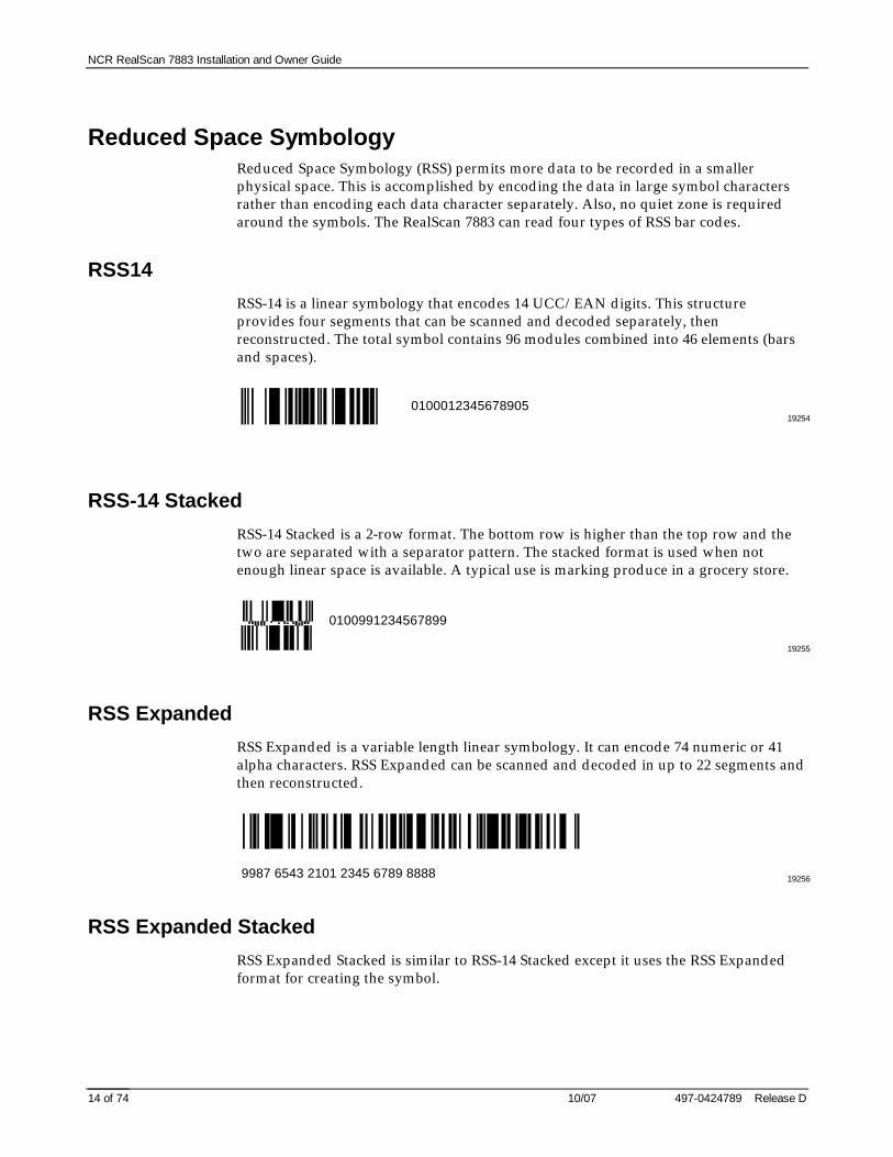
Reduced Space SymbologyReduced Space Symbology (RSS) permits more data to be recorded in a smallerphysical space. This is accomplished by encoding the data in large symbol charactersrather than encoding each data character separately. Also, no quiet zone is requiredaround the symbols. The RealScan 7883 can read four types of RSS bar codes.
RSS14
RSS-14 is a linear symbology that encodes 14 UCC/EAN digits. This structureprovides four segments that can be scanned and decoded separately, thenreconstructed. The total symbol contains 96 modules combined into 46 elements (barsand spaces).
192540100012345678905
RSS-14 Stacked
RSS-14 Stacked is a 2-row format. The bottom row is higher than the top row and thetwo are separated with a separator pattern. The stacked format is used when notenough linear space is available. A typical use is marking produce in a grocery store.
19255
0100991234567899
RSS Expanded
RSS Expanded is a variable length linear symbology. It can encode 74 numeric or 41alpha characters. RSS Expanded can be scanned and decoded in up to 22 segments andthen reconstructed.
192569987 6543 2101 2345 6789 8888
RSS Expanded Stacked
RSS Expanded Stacked is similar to RSS-14 Stacked except it uses the RSS Expandedformat for creating the symbol.

NCR RealScan 7883 Installation and Owner Guide
497-0424789 Release D 10/07 15 of 74
19257
0192 1234 5698 7457 3202 0000 9939 0200 296
Enabling RSS1. Turn on the circuit breaker to the RealScan 7883.2. Enable the Reduced Space Symbology feature by scanning the following sequence
of programming tags. These must be the first tags scanned after applying power tothe unit.• Programming Mode - Puts the RealScan 7883 in the Programming Mode.• Hex 1, Hex 8, Hex A, Hex 3.• Save and Reset - Saves the parameter setting.
Disabling RSS1. Turn on the circuit breaker to the RealScan 7883.2. Enable the Reduced Space Symbology feature by scanning the following sequence
of programming tags. These must be the first tags scanned after applying power tothe unit.• Programming Mode - Puts the RealScan 7883 in the Programming Mode.• Hex 1, Hex 8, Hex A, Hex 0.• Save and Reset - Saves the parameter setting.
Making Other Program ChangesIf you still need to make program changes after setting the communication parameters,you can enter information directly from the Programming Worksheets. TheProgramming Worksheets, located at the back of this book, identify all the availableprogram parameters. Each worksheet relates to a specific programming mode. Mostprogramming options have defaults, identified by a heavy box, that are determined atthe factory. Scanning the Default tag as the first tag after applying power to theRealScan 7883 sets the parameters to these values.
Changing the RealScan 7883 program is accomplished by scanning the propersequence of programming tags, which are included with the unit. Following are threemajor steps for making program changes.
1. Enter the Base Programming State by scanning the Programming Mode tag as thefirst tag after applying power to the RealScan 7883.
2. Select a Programming Worksheet and enter its parameter data by scanning theappropriate Hex tags.
3. Save the program by scanning the Save and Reset tag.
Note: In most instances the factory determined defaults are the correct parametersetting. However, if you do need to make changes, it is recommended that you first setall parameters to default values, then make any necessary changes to the appropriateparameters.

NCR RealScan 7883 Installation and Owner Guide
10/07 497-0424789 Release D16 of 74
Scan Sample TagsNow you should scan some sample tags to verify that the RealScan 7883 iscommunicating with the host terminal. Following are four good tags that you can use.After verifying that the RealScan 7883 is communicating properly with the hostterminal, continue with the installation.
Note: For maximum performance, full size labels must be used. The UPC SymbolSpecification Manual gives the exact size requirements for UPC labels. If the bar heightis less than specified, more precise presentation to the scanner is required, reducingproductivity.
UPC-A
1 7 7 0 6 2 3 7 9 2 0 4
Code 39
1 7 7 0 6 2 3 7 9 2 0
Code 128
1 7 7 0 6 2 3 7 9 2 0
Interleaved 2 of 5
0 1 7 7 0 6 2 3 7 9 2 0

NCR RealScan 7883 Installation and Owner Guide
497-0424789 Release D 10/07 17 of 74
Determining Label QualityMany labels in a typical retail environment are unreadable. The following illustrationshows some of the common problems. Vendors and printers regularly supply productsto the market with bar codes that are overprinted, underprinted, or truncated. Somelabels have missing margins. Others may be printed around the corners of packages, oron media not likely to remain flat when picked up.
01234 6785 90 6
01234 6785 90 6
01234 6785 90 6
R0026
01234 6785 90 6
01234 6785 90 601234 6785 90 6
Bar Code Scratched Bar Code Folded Bar Code Truncated
Bar Code Torn Poor Color Contrast Red Bar Code OnRed Background
The readability of a label depends on variables such as size, placement, color, papertype, ink viscosity, and package coatings. The middle of a printing run can yielderroneous labels due to the many variants involved. In particular, poor color contrastand marginal print quality can make a label hard to read.
UPC bar code requirements are identified in the UPC Symbol Specification Manualthat is published by the Uniform Code Council, Inc. Contact the following for a copy ofthis document.
Uniform Code Council, Inc.8163 Old Yankee Road, Suit JDayton, OH 45458Phone: 513-435-3870
Contact the following for information on Code 39 or "3 of 9" bar code labels.
AIM – USA634 Alpha Dr.Pittsburgh, PA 15238-2802Phone: 412-963-8588
EAN bar code requirements are identified in General Specification for ArticleSymbol Marking, Copyright EAN-1977.

NCR RealScan 7883 Installation and Owner Guide
10/07 497-0424789 Release D18 of 74
Step 3 - Setting RealScan 7883Scan Zone
The scan zone on a NCR RealScan 7883 Scanner can be set to horizontal or vertical.Changing the scan zone changes the angle of the scan lines coming from the scanner.
16011
HorizontalScanning
VerticalScanning
You change the scan zone by turning the screw on the bottom of the cabinet. Be sure toturn the screw all the way in one direction or the other, do not leave it turned partway.
Complies with FDA radiationPerformance standards 21CFR Subchapter J.
One or more of the U.S. Patents listed below apply:
4,868,375 4,797,551 4,851,667 4,235,018 4,272,675 4,282,426, 4,679,154 5,194,722 5,276,316 5,334,825 5,262,625 5,256,865 5,144,114 5,065,842 5,023,818 5,459,310 5,588,621 5,661,297 5,773,767 5,975,417
This device complies with Part 15 of the FCC Rules. Operation is subject to
the following two conditions: (1) This device may not cause harmful interference, and (2) this device must accept any interference received
including interference that may cause undesired operation.
This apparatus does not exceed the Class A limits for radio noise emissions set out in the Radio Interference Regulations of Canada.
Le présent appareil ñ émet pas de bruits radioeléctriques depassant les limites de la Classe A prescrites dans le Reglement sur le brouillage radioeléctrique du Canada.
VCCI-1
NCR CorporationDuluth, Ga. 30096
Horizontal
Vertical
Class: 7883 Serial:Model: Made In:Date Manufactured:5/12/ -12VDC; 1.2/0.4/0.2A 15W (max)
LISTEDI.T.E.
E152553
Scan ZoneAdjusting Screw
20152
When selecting the scan zone, you must also consider how you are mounting thescanner, horizontally or vertically. This permits you to optimize the performance foryour particular installation. Following are four common installations that identify theinstallation type and the scan zone setting. They are given in order of scanningefficiency with the first being the most efficient, and the last being the least.

NCR RealScan 7883 Installation and Owner Guide
497-0424789 Release D 10/07 19 of 74
Horizontal - Pass-by ScanningThis installation provides the most efficient way to scan items. It is typically used incheckouts where speed is extremely important. In this installation, the operator slidesitems from the input area on the checkstand, across the scanner, and to the output areaon the checkstand.
16012
Typical Installation - Hyper/Super Market
Scan Zone - Horizontal
Installation - Horizontal
Vertical - Pass-by ScanningThis installation is used where the checkstand is not large enough to mount thescanner horizontally, but pass-by scanning is needed. In this installation, the operatorslides items from the input area on the checkstand, past the scanner, and to the outputarea on the checkstand.
Typical Installation - Drug Stores Super Market in Europe With Operator Seated
Scan Zone - Horizontal
Installation - Vertical
16013
OR

NCR RealScan 7883 Installation and Owner Guide
10/07 497-0424789 Release D20 of 74
Vertical - Presentation Scanning from TopThis installation is used on small checkout counters that do not have enough room forpass-by scanning. Here the operator picks up the item, presents it toward the top of thescanner, and then bags the item all in one motion.
16014
Typical Installation - Specialty Store
Scan Zone - Vertical
Installation - Vertical
Vertical - Presentation Scanning from BottomThis installation is used on very small checkout counters. In this installation theoperator picks up the item, presents it toward the bottom of the scanner, and then bagsthe item all in one motion.
16015
Typical Installation - Convenient Store
Scan Zone - Vertical
Installation - Vertical

NCR RealScan 7883 Installation and Owner Guide
497-0424789 Release D 10/07 21 of 74
Step 4 - Mounting theRealScan 7883
Rubber FeetThe NCR RealScan 7883 Scanner is supplied with rubber feet that can be attached tothe sides of the cabinet. This permits the scanner to sit on the checkstand in a verticalposition without being mounted to the Vertical Mounting Bracket. There are roundrecesses in each side of the cabinet that accept the rubber feet. Remove the paperbacking from the rubber feet and stick them to the cabinet in the round recesses.
Plastic Top PlateYour installation may use a Plastic Top Plate. Make sure no rubber feet are attached tothe cabinet.
1. Properly align the scanner with the Plastic Top Plate.2. Fasten the scanner to the Top Plate making sure that all four latches are securely
latched around the scanner.
Plastic Top Plate
Mounting Latches
19770B
Scanner

NCR RealScan 7883 Installation and Owner Guide
10/07 497-0424789 Release D22 of 74
3. Install two Latch Clips – horizontal installation only. These clips secure theRealScan 7883 to the Plastic Top Plate in case something falls on the assembledunit.
DC
Plastic Top Plate
Latch Clip
19771
Scanner
Mounting Screw

NCR RealScan 7883 Installation and Owner Guide
497-0424789 Release D 10/07 23 of 74
Vertical Mounting Bracket
Laser ScanDirection
Laser ScanDirection
Laser ScanDirection
Vertical Mount BracketScanner
Interface Cable
Power Cable
Mounting Screws (Three)
Ground Wire
16016
RS-232 Peripheral Cable

NCR RealScan 7883 Installation and Owner Guide
10/07 497-0424789 Release D24 of 74
Checkstand Cutout1. Put the RealScan 7883 into the hole in the checkstand. Diagrams in NCR
RealScan 7883 Specifications show the various dimensions of the hole.2. Align the RealScan 7883 to the Checkstand. The leading edge of the Top Plate must
be flush or up to 1/16 in. (0.15 cm) below the top of the checkstand. The trailingedge of the Top Plate must be flush or up to 1/16 in. (0.15 cm) above the top of thecheckstand.
Correct Alignment
High SurfaceLow SurfaceHigh SurfaceLow Surface
14231Scanner Too LowBad Alignment
Bad AlignmentScanner Too High
Checkpoint CableIf you are installing a RealScan 7883 Scanner, with the Checkpoint feature, on a VerticalMounting Bracket, route the Checkpoint Cable along side the Interface Cable.
Note: If the installation includes the Checkpoint feature, a representative fromCheckpoint must connect the Checkpoint Cable to the Checkpoint equipment after youinstall the RealScan 7883.
Cable ClampsThe RealScan 7883 is supplied with two Cable Clamps (006-0687102). Install theseclamps under the checkstand as needed to support the cables and keep them out of theoperator’s way.

NCR RealScan 7883 Installation and Owner Guide
497-0424789 Release D 10/07 25 of 74
Operating the Scanner
The NCR RealScan 7883 is a fixed position device that is not handled or moved by theoperator during operation. It is maintained and serviced by trained service personnelonly. The operator has no access to any laser module components.
The RealScan 7883 does not have a power switch. However, you turn it on and off byusing the circuit breaker switch, located in the checkstand, that supplies power to theunit. Be sure this switch is in the On position.
The Red Indicator is on when the RealScan 7883 is ready. When the scanner reads a barcode, the Red Indicator turns off and the Green Indicator turns on. Nothing happens ifthe bar code is not read. The correct way to do pass-by scanning is to just slide the itempast the scan window without lifting the item. With presentation scanning, you lift theitem, move it straight toward the scan window, then bring the item back away fromthe scanner.
11959
Horizontal Mount In Counter
Motion Detector Red/Green Status Indicator
Scan Window
Item Flow
Vertical MountTable Top Mount

NCR RealScan 7883 Installation and Owner Guide
10/07 497-0424789 Release D26 of 74
Cleaning the Scanner
Keeping the scan windows clean helps keep the read rate exceptionally high. Duringnormal operation the scan windows get dirty, and if you permit the dirt to accumulate,performance degrades to the point where the scanner cannot read bar codes. Use a softcloth to clean the scan windows, using a common, non-abrasive, liquid windowcleaner. Be sure to spray the cleaner onto the cloth, not directly onto the scanner.
15937
Wiping Action

NCR RealScan 7883 Installation and Owner Guide
497-0424789 Release D 10/07 27 of 74
Correcting Scanner Problems
When the RealScan 7883 is first turned on, several diagnostic tests are run to check thestatus of various components. If a failure occurs, a series of beeps and flashes of theGreen Status Indicator identify it. The number of beeps (flashes) identifies the problem.The problem indication is repeated continuously with a 3-second pause between eachindication series. Following the first problem indication, the beeps are turned off andonly the Green Status Indicator flashes to identify the problem.
If the diagnostics identify a problem, you must have the scanner repaired. Refer toObtaining Technical Assistance on page 3. Although several conditions can be identified,following are the most common.
GreenStatusIndicator Tones Problem Suspect Component
2 Flashes 2 Beeps RAM – Write / Read failure Printed Circuit Board
3 Flashes 3 Beeps Spinner motor running whenit should be off
Printed Circuit Board
4 Flashes 4 Beeps Interface Failure Codereceived
Printed Circuit Board
5 Flashes 5 Beeps Motor running too slow • Motor• Printed Circuit Board
6 Flashes 6 Beeps EEPROM failure – cannotload contents into memory
Printed Circuit Board
7 Flashes 7 Beeps No +12 Vdc or –12 Vdc Power Supply
8 Flashes 8 Beeps Laser Diode On when itshould be Off
Printed Circuit Board
11 Flashes 11 Beeps Laser Diode Off when itshould be On
Printed Circuit Board
12 Flashes 12 Beeps ROM sum check failure Printed Circuit Board

NCR RealScan 7883 Installation and Owner Guide
10/07 497-0424789 Release D28 of 74
There are other conditions that are not identified by the diagnostics when you turn onthe RealScan 7883. The following chart identifies some of the more common problems.
ProblemStatusIndicators Tone
PossibleCause Corrective Action
Scanner does notoperate
Red OffGreen Off
Off No power to the unit • Check theelectrical outletfor proper power
• Verify that ACPower Cord isproperlyconnected
Scanner is quiet Red & Green flashingcontinuously
Off Sleep mode • Pass anything infront of themotion detector
Scanner reads onlytwo labels
Red flashing Green Off
Off Communications isIBM 468x and scanneris off-line
• Verify that IBMhost is turned on
• Verify that IBMhost isrecognizing theRealScan 7883
• Verify that theinterface cable isproperlyconnected
Scanner reads onlytwo labels
Red On Green Off
Off NCR 7883 is notcommunicating withthe host
• Check forexpectedcommunicationprotocol
• Check hostterminal forproper operation
• Check interfacecable connections
Scanner does notread any labels
Red flashingrapidly
Off Scanner has beendisabled by the hostterminal
• Terminal shouldenable scannerlater in thetransaction
Scanner does notread any labels
Red On Green Off
Off Internal failure • Remove powerfrom theRealScan 7883and then supplyagain
• Have scannerrepaired

NCR RealScan 7883 Installation and Owner Guide
497-0424789 Release D 10/07 29 of 74
Interface Information
Interface Connector
20151
10 1
123456789
10
RDATARTNRDATA/SDATA/CLKOUT/CLKIN/TERMRTNNCNCNCGND
NCNCNCNCNCNCTMPWRTRATRBGND
DSR (IN)DTR (OUT)TXD (OUT)RTS (OUT)CTS (IN)RXD (IN)NCNCNCGND
NCKBCLK/NCNCNCNCPCCLK/PCDATA/
Pin OCIA IBM RS-232 WEDGE
Ground Lug
Complies with FDA radiationPerformance standards 21CFR Subchapter J.
One or more of the U.S. Patents listed below apply:
4,868,375 4,797,551 4,851,667 4,235,018 4,272,675 4,282,426, 4,679,154 5,194,722 5,276,316 5,334,825 5,262,625 5,256,865 5,144,114 5,065,842 5,023,818 5,459,310 5,588,621 5,661,297 5,773,767 5,975,417
This device complies with Part 15 of the FCC Rules. Operation is subject to the following two conditions: (1) This device may not cause harmful interference, and (2) this device must accept any interference received
including interference that may cause undesired operation.
This apparatus does not exceed the Class A limits for radio noise emissions set out in the Radio Interference Regulations of Canada.
Le présent appareil ñ émet pas de bruits radioeléctriques depassant les limites de la Classe A prescrites dans le Reglement sur le brouillage radioeléctrique du Canada.
VCCI-1
NCR CorporationDuluth, Ga. 30096
Horizontal
Vertical
Class: 7883 Serial:Model: Made In:Date Manufactured:5/12/ -12VDC; 1.2/0.4/0.2A 15W (max)
LISTEDI.T.E.
E152553
Most Common Interface Cables• 1416-C011-0040 OCIA Single Cable• 1416-C019-0040 RS-232 to PC• 1416-C020-0040 IBM port 17• 1416-C070-0040 IBM port 9A/9E• 1416-C142-0040 IBM port 5B• 1416-C676-0030 PS/2 Keyboard wedge

NCR RealScan 7883 Installation and Owner Guide
10/07 497-0424789 Release D30 of 74
Communications ProtocolThe Communications Protocol function identifies the communications protocol theRealScan 7883 is using. Scan the Diagnostics Mode and Hex 3 programming tags(must be first tags scanned after applying power). Three beeps sound after scanningthe Hex 3 tag, identifying the programming tag. Next, the Status Indicator flashesgreen and a series of beeps sound that identify the communications protocol. Use thefollowing table to determine the communication protocol.
Tone Communication Protocol1 Beep (Short high pitched) OCIA NCR Short / Datachecker1 Beep OCIA NCR Long2 Beeps OCIA Non-NCR3 Beeps IBM 468x (4A)4 Beeps IBM 468x (4B)6 Beeps RS-2327 Beeps OCIA Single-Cable
10 Beeps Keyboard Wedge11 Beeps Casio / OCIA Non-NCR
Scan the Hex 3 tag to repeat; remove power to end.
Programming Worksheet
COMMUNICATIONS PROTOCOL1 0
ProtocolOCIA
NCR LongIBM
Slot ScannerOCIA
Non NCRDual Cable
OCIASingle Cable
RS-232
CasioDual Cable
OCIA NCRDual Cable
IBMHand-HeldBar CodeReader
0
OCIANCR Short
(Datachecker)
IBM 1520 Bar CodeReader
TECDual Cable
IBM USB
14391A
1 2 3 4 5
6 7 A B C D
E 0
NCR (RS-232) USB

NCR RealScan 7883 Installation and Owner Guide
497-0424789 Release D 10/07 31 of 74
NCR RealScan 7883Specifications
Checkstand Hole –RealScan 7883 Horizontal Mount
11981
E
SIDE VIEW
C
Item Flow
D
C
D
E
A B C D E
8 5/8 in.21.91 cm
8 5/8 in.21.91 cm
1/16 in.0.16 cm
1 1/16 in.2.70 cm
1/2 in.1.27 cm
Features
F062
9 5/8 in.24.45 cm
11 5/16 in.28.73 cm
1/16 in.0.16 cm
1 1/16 in.2.70 cm
1/2 in.1.27 cm
K011 (7852 Mount)
20 1/8 in.51.12 cm
11 5/8 in.29.53 cm
1/16 in.0.16 cm
13/32 in.1.03 cm
7/16 in.1.11 cm
K010 (7820 Mount)
A
B
B

NCR RealScan 7883 Installation and Owner Guide
10/07 497-0424789 Release D32 of 74
Checkstand Hole –RealScan 7883 Flat Mount
11993
SIDE VIEW
A B C DFeatures8 3/4 in.22.22 cm
8 3/4 in.22.22 cm
1/16 in.0.16 cm
1/16 in.0.16 cm
K012
A
B
C
Item Flow
D
C
BD

NCR RealScan 7883 Installation and Owner Guide
497-0424789 Release D 10/07 33 of 74
Ventilation RequirementsThe NCR RealScan 7883 is designed to operate without an exhaust fan in thecheckstand; however, there must be adequate convection air flow. The ambienttemperature inside the checkstand cannot be higher than 104° F (40° C). Also, theambient temperature inside the checkstand cannot be higher than 12.6° F (7° C) abovethe ambient temperature outside the checkstand. For example, if the ambienttemperature outside the checkstand is 76° F (24.4° C), the ambient temperature insidethe checkstand cannot be greater than 88.6° F (31.4° C). If the checkstand contains otherheat producing equipment, you may need to use forced air to keep the temperaturewithin the specified range. However, air coming into or leaving the checkstandMUST NOT enter or exit past the RealScan 7883.
Electrical Wiring
Feeder wiring and insulated ground frommain service panel to distribution panelto be run in metal conduit.
The electrical wiring must meet allelectrical codes, laws, and regulations.
Note:
Circuit Breakers
NCR circuits should be run inseparate metal Conduits.
Isolated/InsulatedGround Bus
Isolated Ground Receptacles
Neutral andGround Bus
NeutralBus
InputVoltage
Input Voltage L1, L2 Circuit BreakersU.S., Canada, &Japan
European
International
100Vac to 120Vac
220Vac
220Vac to 240Vac
100Vac to 120Vac
220Vac
220Vac to 240Vac
Standard single-pole; valuedetermined by type of devicebranch and by electrical code.
European double-pole.
Circuit B: Terminal
Installation Type
NCR circuits must be dedicated toNCR equipment or other logicallyconnected electronic equipment(modems, DAA, bridges, etc.)
Note:
Circuit C: ScannerReceptacle should be easilyaccessible and near the scanner
L2
L3
Distribution Panel
Main ServicePanel
Conduit
CheckstandFrame
Circuit A: Checkstand
BeltMotor
Belt ControlLighting
Misc. Equip.N
G
L1
20254

NCR RealScan 7883 Installation and Owner Guide
10/07 497-0424789 Release D34 of 74
NCR RealScan 7883,METTLER TOLEDO® Scale, &
Sensormatic ScanMaxTMHS
20203
The NCR RealScan 7883, METTLER TOLEDO® 8217AS, & Sensormatic ScanMaxTMHSsystem is composed of components from three companies. NCR manufactures thescanner, METTLER TOLEDO manufactures the scale, and Sensormatic manufacturesthe tag deactivation system. Depending upon the customers' requirements, any one ofthese companies, or a combination of them, may fill an order for the system and mayinstall or service it. Therefore, the system may be delivered in three separate boxes orall together in one box. More information is available at the following.
• www.mt.com or call 614-438-4771• www.Sensormatic.com or call 561-912-6544
NCR Components
20204
RealScan 7883
Power Supply
Reset Scale Tag
Scale / InterlockCable
Velcro MountingStrips
InterfaceCable
PowerCable

NCR RealScan 7883 Installation and Owner Guide
497-0424789 Release D 10/07 35 of 74
METTLER TOLEDO Components
20206
Bridge PlateTop Plate
Mounting BracketWith Scale Attached
Sensormatic Components
20207
ControllerBox
DeactivationBrick
Key SwitchAlarm Box
AC PowerCord
NCR RealScan 7883 Installation and Owner Guide
10/07 497-0424789 Release D36 of 74
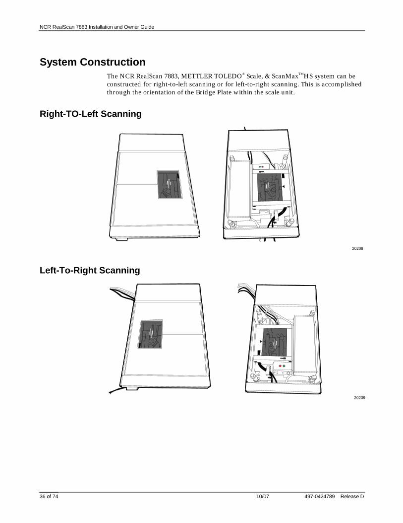
System ConstructionThe NCR RealScan 7883, METTLER TOLEDO® Scale, & ScanMaxTMHS system can beconstructed for right-to-left scanning or for left-to-right scanning. This is accomplishedthrough the orientation of the Bridge Plate within the scale unit.
Right-TO-Left Scanning
20208
Left-To-Right Scanning
20209

NCR RealScan 7883 Installation and Owner Guide
497-0424789 Release D 10/07 37 of 74
Configuring the ScaleFirst determine if the system needs to be configured for scanning from right-to-left orfrom left-to-right. Install the Bridge Plate on the scale unit inside the Mounting Bracketaccordingly.
Right-To-Left
20210
Left-To-Right
20211

NCR RealScan 7883 Installation and Owner Guide
10/07 497-0424789 Release D38 of 74
Installing the Scanner1. Using the Velcro Strips provided by NCR, attach the Key Switch Alarm Box to the
RealScan 7883 as shown.
Note: The top of the Key Switch Alarm Box must be below the top of theRealScan 7883. Refer to the illustrations under Configuring the Scale.
2. Connect the Power Cable, Interface Cable, and the Scale Cable to the RealScan7883.
20212
Interface Cable
Power Cable
Scale Cable
Key SwitchAlarm Box
3. Position the RealScan 7883 on top of the Bridge Plate as shown under Configuringthe Scale. The Scale Cable runs through a slot in the Bridge Plate.
20213
Interface Cable
PowerCable
ScaleCable

NCR RealScan 7883 Installation and Owner Guide
497-0424789 Release D 10/07 39 of 74
Connecting Sensormatic Components1. Position the Deactivation Brick on top of the Bridge Plate as shown under
Configuring the Scale. The cable from the Deactivation Brick must be routed fromthe bottom of the brick toward the center of the Bridge Plate.
20214
Deactivation Brick Cable
2. Connect the cables to the Controller Box.
20215
Interlock Cable - From Scanner
Key SwitchAlarm Box Cable
DeactivationBrick Cable

NCR RealScan 7883 Installation and Owner Guide
10/07 497-0424789 Release D40 of 74
Routing the CablesHow the cables are routed depends on the configuration, right-to-left or left-to-rightscanning. In either case the cables are held in place with a cable clamp attached to theBridge Plate.
Right-To-Left ScanningCustomer End
20216
Checkout System End
20217

NCR RealScan 7883 Installation and Owner Guide
497-0424789 Release D 10/07 41 of 74
Left-To-Right ScanningCustomer End
20218
Checkout System End
20219
Completing the InstallationPosition the unit inside the cutout in the self-checkout terminal. Then install the TopPlate. The Top Plate must positioned correctly for the type of scanning. Refer toConfiguring the Scale.

NCR RealScan 7883 Installation and Owner Guide
10/07 497-0424789 Release D42 of 74
Calibrating the METTLER TOLEDO® Scale1. Use a screw driver or car key to pry up the Top Plate until you can get hold of it,
then lift if off the unit.
20220
2. Remove the Calibration Switch cover screw.
20221
Calibration SwitchCover Screw
3. Press the Calibration Button. One short beep per second starts to sound.4. Place the Top Plate on the scale. Do not put anything on the Top Plate.5. Scan the Reset Scale tag. Two short beeps per second start to sound.6. Place 20 pounds on the Top Plate.7. Scan the Reset Scale tag. One long beep per second starts to sound.8. Remove the 20 pounds from the Top Plate.9. Scan the Reset Scale tag. All beeps stop.10. Replace the Calibration Switch Cover Screw.11. Scan the Reset Scale tag.

NCR RealScan 7883 Installation and Owner Guide
497-0424789 Release D 10/07 43 of 74
Sensormatic Deactivation IndicatorsThe Key Switch Alarm Box that is fastened to the RealScan 7883 with Velcro strips,contains two indicators to indicate the status of the unit.
• Solid Green – Unit has received an interlock signal.• Flashing Green – Unit has power.• Flashing Red – Unit is deactivating a tag.
20222
Red Indicator
Green Indicator
Sensormatic Programmable FunctionsYou can program the RealScan7883 to enable or disable the Sensormatic interlock. Theinterlock must be enabled for the Sensormatic deactivation function to work. You canalso program the RealScan7883 to sound a series of beeps when deactivation occurs.This programming is accomplished by scanning the proper sequence of programmingtags as the first tags scanned after applying power to the scanner.
• Enable InterlockProgramming Mode, Hex 4, Hex 2, Hex B, Save and Reset
• Disable InterlockProgramming Mode, Hex 4, Hex 2, Hex A, Save and Reset
• Enable Deactivation BeepsProgramming Mode, Hex 4, Hex B, Hex B, Save and Reset
• Disable Deactivation BeepsProgramming Mode, Hex 4, Hex B, Hex A, Save and Reset

NCR RealScan 7883 Installation and Owner Guide
10/07 497-0424789 Release D44 of 74
TroubleshootingFor the most part, the function of each of the three units; scanner, scale, anddeactivation unit; work independently from each other. However, there are someinteractions. Following are some basic things to check if the system is not workingproperly. You may need to refer to the manufacturer's documentation for each unit.
Scanner Problems
If the scanner does not operate, check the following.
• Power Cable connections.• Interface Cable connections.• Red laser light is being generated.• Spinner mirrors are rotating.• Diagnostic failures (see Installation Guide).
Scale Problems
If scale is not weighing items properly, check the following.
• Scanner Power Cable connections.• Scanner Interface Cable connections.• Scale Cable connection to the RealScan 7883.• Program RealScan 7883 to enable scale by scanning the following sequence of tags
Programming Mode, Hex 3, Hex 0, Hex 3, Save and Reset.
If the scale is still not weighing items properly, perform the following.
1. Remove all items from the Top Plate.2. Scan the Reset Scale tag – Scale should read 0.00.3. Put some weight on the Top Plate – Scale should read some weight (not 0.00).4. Remove all items from the Top Plate – Scale should read 0.00.5. Remove the Top Plate.6. Remove any debris from the scale mechanism or Top Plate posts.
Sensormatic Deactivation
If the Sensormatic deactivation is not working, check the following.
• Controller Box Power Cable connections.• Scanner Power Cable connections.• Deactivation Brick Cable connection.• Key Switch Alarm Box Cable connections.• Interlock Cable connection (from RealScan 7883).• Program scanner to enable interlock by scanning the following sequence of tags
Programming Mode, Hex 4, Hex 2, Hex B, Save and Reset
NCR RealScan 7883 Installation and Owner Guide
497-0424789 Release D 10/07 45 of 74
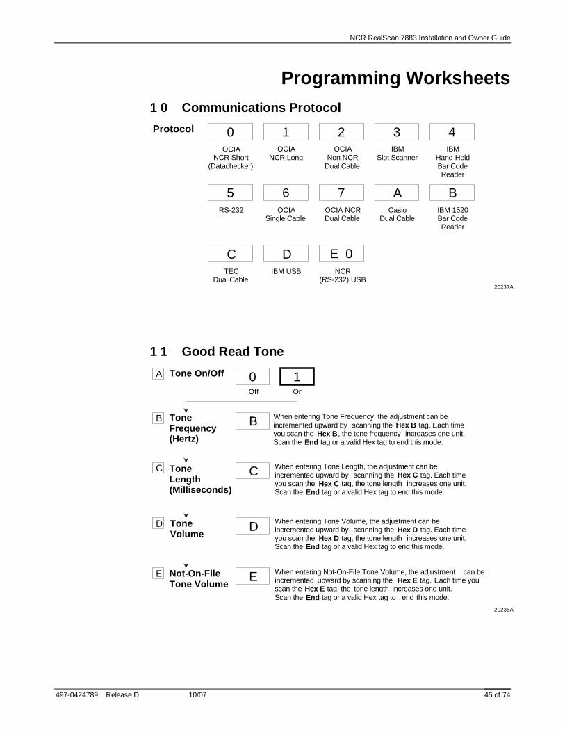
Programming Worksheets
1 0 Communications Protocol
0OCIA
NCR LongIBM
Slot ScannerOCIA
Non NCRDual Cable
IBMHand-HeldBar CodeReader
OCIANCR Short
(Datachecker)
Protocol 1 2 3 4
5OCIA
Single CableOCIA NCRDual Cable
RS-232
6 7Casio
Dual CableIBM 1520Bar CodeReader
A B
CIBM USB NCR
(RS-232) USBTEC
Dual Cable
D E 0
20237A
1 1 Good Read Tone
Tone On/OffA
Off
ToneFrequency(Hertz)
ToneVolume
Tone Length(Milliseconds)
Not-On-FileTone Volume
When entering Tone Frequency, the adjustment can be incremented upward by scanning the Hex B tag. Each time you scan the Hex B, the tone frequency increases one unit. Scan the End tag or a valid Hex tag to end this mode.
When entering Tone Length, the adjustment can be incremented upward by scanning the Hex C tag. Each time you scan the Hex C tag, the tone length increases one unit. Scan the End tag or a valid Hex tag to end this mode.
When entering Tone Volume, the adjustment can be incremented upward by scanning the Hex D tag. Each time you scan the Hex D tag, the tone length increases one unit. Scan the End tag or a valid Hex tag to end this mode.
When entering Not-On-File Tone Volume, the adjustment can be incremented upward by scanning the Hex E tag. Each time you scan the Hex E tag, the tone length increases one unit. Scan the End tag or a valid Hex tag to end this mode.
0
B
On
1
B
C C
D D
E E
20238A

NCR RealScan 7883 Installation and Owner Guide
10/07 497-0424789 Release D46 of 74
1 2 Timers
Lockout Time(Milliseconds)
A
Restart Lockout Timer
B
Active Time(Minutes)
C
NOTE: NCR suggests that you do not set the Active Timeparameter to 0. Leaving the laser light on all the time reducesits life expectancy.
NOTE: To use E or F, first scan the Hex A tag. Then scan the Hex E or Hex F tags as needed, followed by the End tag.
350
8450
0600
1750
2900
3
1050
41200
51350
61500
7
Decrement 50
EIncrement 50
F
Off
0On
1
0
010
115
220
325
4
20239A

NCR RealScan 7883 Installation and Owner Guide
497-0424789 Release D 10/07 47 of 74
1 3 Bar Codes – 1UPC/EAN 0
Disable
A 1Enable
B Version D 0Disable
C Extend UPC-ATo EAN-13
0Disable
1Enable
D Extend UPC-ETo UPC-A
0Disable
1Enable
E PeriodicalCodes
0Disable
1Enable
F PeriodicalCodeExtension
02-DigitOnly
15-DigitOnly
22-Digit &5-Digit
Send Data 0Data ASDecoded
1All Data If
Periodical CodePresent
2CF Hex ExtensionIf Periodical Data
Not Decoded 20240A

NCR RealScan 7883 Installation and Owner Guide
10/07 497-0424789 Release D48 of 74
1 4 Bar Codes - 2
Code 39A 0Disable
1Enable
MinimumCharactersAllowed
B 82 - F Default
Full ASCIIC 0Disable
1Enable
Check DigitPresent
D 0Disable
1Enable
TransmitCheck Digit
E 0Disable
1Enable
Allow 1- or2-CharacterTags
F 0Disable
1Enable
20241-A

NCR RealScan 7883 Installation and Owner Guide
497-0424789 Release D 10/07 49 of 74
1 5 Bar Codes - 3
Interleaved2 of 5
Bar CodeLength
Check DigitPresent
TransmitCheck Digit
Value 1 CharactersMinimum
Default:
Value 2 CharactersMaximum
A
B
C
D
0 8
Default: 1 6
0Disable
1Enable
0RangeCheck
SpecificCheck
0 - 3Character 1
0 - 9Character 2
0 - 3Character 1
0 - 9Character 2
1
0Disable
1Enable
0Disable
1Enable 20242-A
1 7 Bar Codes - 4
Code 128A 0Disable
1Enable
Minimum DataCharactersAllowed
B 1 2 3 4 5
UCC 128C 0Disable
1Enable 20243-A

NCR RealScan 7883 Installation and Owner Guide
10/07 497-0424789 Release D50 of 74
1 6 Label Identifiers
Common Byte 1B
Common Byte 2C
Bar Code TypeD
1
Common Byte
Unique Identifier
0 - 7 5 Default
Hex Character(ASCII Code Chart)
0 - 7Hex Character
(ASCII Code Chart)
0 - 7 Default
Hex Character(ASCII Code Chart)
0 - 7Hex Character
(ASCII Code Chart)
Identifier TypeDefault Prefix
ANone Unique Prefix
0 2 3
UPC-A
0UPC-E
2EAN-8
3EAN-13
4
Code 39
5Code 128
6Interleaved
2 of 5
7
None
0Common Byte 1
1Common Byte 2
2Both Common Bytes
3
10 - 7Hex Character
(ASCII Code Chart)
0 - FHex Character
(ASCII Code Chart)
Common Byte andUnique Identifier Defaults varyaccording to Bar Code Type
D
4 2
20244-A
2 0 RS-232 Parameters - 1
Baud RateA 0300
1600
21200
32400
44800
59600
619200
ParityB
Stop BitsAndCharacterLength
C
HandshakeD
0Odd
1Even
4None
01 Stop Bit
7-Bit Character
11 Stop Bit
8-Bit Character
22 Stop Bits
7-Bit Character
32 Stop Bits
8-Bit Character
0RTS Low
Ignore CTS
1RTS High
Ignore CTS
2Raise RTSWait For
CTS
3Raise RTSIgnore CTS
4RTS LowWait For
CTS
5RTS HighWait For
CTS20245-A

NCR RealScan 7883 Installation and Owner Guide
497-0424789 Release D 10/07 51 of 74
2 1 RS-232 Parameters - 2
Note: Check Digit parameter also applies to UPC-Ewhen using OCIA communications.
BCC OptionsA
Interface ControlB
Check DigitC
0Disable
1Enable
0None
1ACK/NAK
2XOn/XOff
3ACK/NAK
&XOn/XOff
5Special
ACK/NAK
0Disable UPC-ADisable EAN-8Disable EAN-113Disable UPC-E
1Enable UPC-AEnable EAN-8Enable EAN-113Disable UPC-E
2Disable UPC-ADisable EAN-8Disable EAN-113Enable UPC-E
3Enable UPC-AEnable EAN-8Enable EAN-113Enable UPC-E
20246-A
2 2 RS-232 Prefix Byte
Prefix ByteA
ASCII CodeB
0Disable
1Enable
0 - 7Hex Character
(ASCII Code Chart)
0 - FHex Character
(ASCII Code Chart)
0 Default2
20247-A
2 4 RS-232 Terminator Byte
Terminator ByteA
ASCII CodeB
0Disable
1Enable
0 - 7Hex Character
(ASCII Code Chart)
0 - FHex Character
(ASCII Code Chart)
0 Default3
20248-A

NCR RealScan 7883 Installation and Owner Guide
10/07 497-0424789 Release D52 of 74
2 4 RS-232 Communications Options
Message Delay
Normal orEavesdropMode
No Delay
010 ms Delay
1
Normal Mode
6Eavesdrop
Mode
7
50 ms Delay
2
20249-A
3 2 Miscellaneous Parameters
IBM Tone Control(Good Read Tone Control)
IBM Rexmit Control
IBM Tag Data Format
Disable
3Enable
4
3 Times
7Forever
8
Hex
EASCII
F
20250A

NCR RealScan 7883 Installation and Owner Guide
497-0424789 Release D 10/07 53 of 74
ASCII Code Chart
70
71
72
7374
75
76
77
78
79
7A
7B7C
7D
7E
7F
p
q
r
s
t
u
v
w
x
y
z
{
|
}
DEL
60
61
62
6364
65
66
67
68
69
6A
6B6C
6D
6E
6F
a
b
c
d
e
f
g
h
i
j
k
l
m
n
o
50
51
52
5354
55
56
57
58
59
5A
5B5C
5D
5E
5F
P
Q
R
S
T
U
V
W
X
Y
Z
[
\
]
^
_
40
41
42
4344
45
46
47
48
49
4A
4B4C
4D
4E
4F
@
A
B
C
D
E
F
G
H
I
J
K
L
M
N
O
30
31
32
3334
35
36
37
38
39
3A
3B3C
3D
3E
3F
0
1
2
3
4
6
5
7
8
9
:
;
<
=
>
?
20
21
22
2324
25
26
27
28
29
2A
2B2C
2D
2E
2F
SP
!
"
#
$
%
&
'
(
)
*
+
,
-
.
/
10
11
12
1314
15
16
17
18
19
1A
1B1C
1D
1E
1F
DLE
DC1
DC2
DC3
DC4
NAK
SYN
ETB
CAN
EM
SUB
ESC
FS
GS
RS
US
00
01
02
0304
05
06
07
08
09
0A
0B0C
0D
0E
0F
NULL
SOH
STX
ETX
EOT
ENQ
ACK
BEL
BS
HT
LF
VT
FF
CR
S0
S1
ASCII Code Chart
~
R0040

NCR RealScan 7883 Installation and Owner Guide
10/07 497-0424789 Release D54 of 74
Regulatory Information
Federal Communications Commission (FCC)Radio Frequency Interference Statement
Note: This equipment has been tested and found to comply with the limits for aClass A digital device, pursuant to Part 15 of the FCC Rules. These limits are designedto provide reasonable protection against harmful interference when the equipment isoperated in a commercial environment. This equipment generates, uses, and canradiate radio frequency energy and, if not installed and used in accordance with theinstruction manual, may cause harmful interference to radio communications.Operation of this equipment in a residential area is likely to cause harmful interferencein which case the user is required to correct the interference at his own expense.
Information to User: This equipment must be installed and used in strict accordancewith the manufacturer’s instructions. However, there is no guarantee that interferenceto radio communications will not occur in a particular commercial installation. If thisequipment does cause interference, which can be determined by turning the equipmentoff and on, the user is encouraged to consult an NCR service representativeimmediately.
Caution: NCR is not responsible for any radio or television interference caused byunauthorized modifications of this equipment or the substitution or attachment ofconnecting cables and equipment other than those specified by NCR. Suchunauthorized modifications, substitutions, or attachments may void the user’sauthority to operate the equipment. The correction of interference caused by suchunauthorized modifications, substitutions, or attachments is the responsibility of theuser.
Voluntary Control Council for Interference (VCCI)Radio Frequency Interference Statement
16105
Canadian Department of CommunicationsRadio Frequency Interference Statement
This digital apparatus does not exceed the Class A limits for radio noise emissionsfrom digital apparatus set out in the Radio Interference Regulations of the CanadianDepartment of Communication.
Le présent appareil numérique n’émet pas de bruits radioélectriques dépassant leslimites applicables aux appareils numériques de la Class A prescrites dans leRèglement sur le brouillage radioélectriques édicté par Ministère des Communicationsdu Canada.

NCR RealScan 7883 Installation and Owner Guide
497-0424789 Release D 10/07 55 of 74
Identification LabelsThe Identification Labels are molded into the bottom of the cabinet. They providenecessary information about the unit: power requirements, radio interferenceinformation, and applicable NCR patents.
19763
NCR CorporationDuluth, Ga. 30096
Complies with FDA radiationPerformance standards 21CFR Subchapter J.
One or more of the U.S. Patents listed below apply:
4,868,375 4,797,551 4,851,667 4,235,018 4,272,675 4,282,426, 4,679,154 5,194,722 5,276,316 5,334,825 5,262,625 5,256,865 5,144,114 5,065,842 5,023,818 5,459,310 5,588,621 5,661,297 5,773,767 5,975,417
This device complies with Part 15 of the FCC Rules. Operation is subject to the following two conditions: (1) This device may not cause harmful interference, and (2) this device must accept any interference received including interference that may cause undesired operation.
This apparatus does not exceed the Class A limits for radio noise emissions set out in the Radio Interference Regulations of Canada.
Le présent appareil ñ émet pas de bruits radioeléctriques depassant les limites de la Classe A prescrites dans le Reglement sur le brouillage radioeléctrique du Canada.
VCCI-1
Horizontal
Vertical
Class: 7883 Serial:Model: Made In:Date Manufactured:5/12/ -12VDC; 1.2/0.4/0.2A 15W (max)
LISTEDI.T.E.
E152553
Complies with FDA radiationPerformance standards 21CFR Subchapter J.
One or more of the U.S. Patents listed below apply:
4,868,375 4,797,551 4,851,667 4,235,018 4,272,675 4,282,426, 4,679,154 5,194,722 5,276,316 5,334,825 5,262,625 5,256,865 5,144,114 5,065,842 5,023,818 5,459,310 5,588,621 5,661,297 5,773,767 5,975,417
This device complies with Part 15 of the FCC Rules. Operation is subject to
the following two conditions: (1) This device may not cause harmful interference, and (2) this device must accept any interference received including interference that may cause undesired operation.
This apparatus does not exceed the Class A limits for radio noise emissions set out in the Radio Interference Regulations of Canada.
Le présent appareil ñ émet pas de bruits radioeléctriques depassant les limites de la Classe A prescrites dans le Reglement sur le brouillage radioeléctrique du Canada.
VCCI-1
NCR CorporationDuluth, Ga. 30096
Horizontal
Vertical
Class: 7883 Serial:Model: Made In:Date Manufactured:5/12/ -12VDC; 1.2/0.4/0.2A 15W (max)
LISTEDI.T.E.
E152553
CE Mark ApplicabilityThis product conforms to the requirements of the following European Union (EU)New Approach Directives.
• 89/336/EECEMC• 73/23/EECLow Voltage

NCR RealScan 7883 Installation and Owner Guide
10/07 497-0424789 Release D56 of 74
Declaration of Conformity
We, NCR Corporation, Retail Solutions Division Atlanta, 2651 Satellite Boulevard,Duluth, Georgia, 30096-5810, U.S.A., declare under our sole responsibility that theproduct NCR RealScan 7883 Bar Code Scanner to which this declaration relates is inconformity with the following standard or other normative document following theprovisions of the noted Directives.
EU Directive Harmonized Standard(s)89/336/EEC (EMC) EN 55022: 1994 + A1 (1995) + A2 (1997)
EN 50082-1, Part 1 (1992)IEC 801-2: 1984, Severity Level 3IEC 801-3: 1984, Severity Level 2IEC 801-4: 1988, Severity Level 2
72/23/EEC (Low Voltage) EN 60950: 1992 A1, A2, A3, A4, and A11EN 60825-1: 1993+A1+A2
Director of Quality Assurance European ContactNCR CorporationRSD-Atlanta2651 Satellite BoulevardDuluth, GA 30096-5810U.S.A.
EU Patent AttorneyNCR Limited206 Marylebone RoadLondon NW1 6LYEngland

NCR RealScan 7883 Installation and Owner Guide
497-0424789 Release D 10/07 57 of 74
Laser Safety
The NCR RealScan 7883 is not intended for long-term viewing of the direct laser light.However, the unit is safe if used as it was intended.
Note: The NCR RealScan 7883 is a CDRH Class IIa and IEC Class 1 Laser Product
Laser Safety Label
18546
(IEC CLASS 1 LASER PRODUCT)
CDRHClass IIa Laser Product - Avoid
Long-Term Viewing of Direct Laser Light.
Appareil à Laser de classe I Ia EviterToute Exposition Prolongeè de la vueà la lumierè laser directe.Producto Laser de Clase IIa. Evite laExposiciòn Prolongada de la vista ala Luz del Rayo Laser.
(IEC CLASS 1 LASER PRODUCT)
CDRHClass IIa Laser Product - Avoid
Long-Term Viewing of Direct Laser Light.
Appareil à Laser de classe IIa EviterToute Exposition Prolongeè de la vueà la lumierè laser directe.Producto Laser de Clase IIa. Evite laExposiciòn Prolongada de la vista ala Luz del Rayo Laser.
(IEC CLASS 1 LASER PRODUCT)
CDRHClass IIa Laser Product - Avoid
Long-Term Viewing of Direct Laser Light.
Appareil à Laser de classe IIa EviterToute Exposition Prolongeè de la vueà la lumierè laser directe.Producto Laser de Clase IIa. Evite laExposiciòn Prolongada de la vista ala Luz del Rayo Laser.
Product Laser Classe IIa. Evite othar directamente os raios laser por muita tempo.

NCR RealScan 7883 Installation and Owner Guide
10/07 497-0424789 Release D58 of 74
Laser Module Label
This laser moduledoes not complywith 21CFR1040.USE ONLY AS ACOMPONENT.
18547
Laser PowerThe NCR RealScan 7883 meets the following laser power requirements.
• Class 1 EN 60825-1: 1994 (Europäische Norm)• Class 1 IEC 825-1: 1993 (International Electrotechnical Commission)• Class IIA CDRH (Center for Devices and Radiological Health) FDA, U.S.A.
Following is the radiant energy of the laser light as applied to each of the specifiedrequirements.
Maximum Radiant Power (CDRH Calculation) 2.7 MicrowattsMaximum Radiant Power (EN 60825-1 / IEC Calculation) 0.82 MilliwattsAccessible Emission Limit (CDRH Calculation) 3.9 MicrowattsAccessible Emission Limit (EN 60825-1 / IEC 825-1 Calculation) 0.80 Milliwatts
Warning – Use of controls or adjustments or performance of procedures other thanspecified herein may result in hazardous radiation exposure.

NCR RealScan 7883 Installation and Owner Guide
497-0424789 Release D 10/07 59 of 74
Programming Tags
Volume Adjustment
11817
Reset
11818

NCR RealScan 7883 Installation and Owner Guide
10/07 497-0424789 Release D60 of 74
Default
R0046
Programming Mode
R0042

NCR RealScan 7883 Installation and Owner Guide
497-0424789 Release D 10/07 61 of 74
End
R0043
Save and Reset
R0044

NCR RealScan 7883 Installation and Owner Guide
10/07 497-0424789 Release D62 of 74
Abort
R0045
Diagnostic Mode
R0041

NCR RealScan 7883 Installation and Owner Guide
497-0424789 Release D 10/07 63 of 74
RS-232 Temporary Service Mode
16576
Mode 1
11500

NCR RealScan 7883 Installation and Owner Guide
10/07 497-0424789 Release D64 of 74
Mode 2
11501
Reset Tallies
11502

NCR RealScan 7883 Installation and Owner Guide
497-0424789 Release D 10/07 65 of 74
Hex 0
R0048
Hex 1
R0049

NCR RealScan 7883 Installation and Owner Guide
10/07 497-0424789 Release D66 of 74
Hex 2
R0050
Hex 3
R0051

NCR RealScan 7883 Installation and Owner Guide
497-0424789 Release D 10/07 67 of 74
Hex 4
R0052
Hex 5
R0053

NCR RealScan 7883 Installation and Owner Guide
10/07 497-0424789 Release D68 of 74
Hex 6
R0054
Hex 7
R0055

NCR RealScan 7883 Installation and Owner Guide
497-0424789 Release D 10/07 69 of 74
Hex 8
R0056
Hex 9
R0057

NCR RealScan 7883 Installation and Owner Guide
10/07 497-0424789 Release D70 of 74
Hex A
R0058
Hex B
R0059

NCR RealScan 7883 Installation and Owner Guide
497-0424789 Release D 10/07 71 of 74
Hex C
R0060
Hex D
R0061

NCR RealScan 7883 Installation and Owner Guide
10/07 497-0424789 Release D72 of 74
Hex E
R0062
Hex F
R0063

NCR RealScan 7883 Installation and Owner Guide
497-0424789 Release D 10/07 73 of 74

NCR RealScan 7883 Installation and Owner Guide
10/07 497-0424789 Release D74 of 74
Copyright © 2002 by NCR Corporation