Embed Size (px)
Citation preview
RealScan 7875Installation/Owner Guide
16044
497-0001843Release KMarch 27, 2003
Information ProductsRSD-Atlanta
NCR RealScan 7875 Installation/Owner Guide
03/03 497-0001843 Release K2 of 68
The program products described in this book are licensed products of NCRCorporation. It is the policy of NCR to improve products as new technology,components, software, and firmware become available. Therefore, NCR reserves theright to change specifications without prior notice. All features, functions, andoperations described herein may not be marketed by NCR in all parts of the world.Therefore, before using this document, consult your NCR representative or NCR officefor information that is applicable and current.
NOTE: Connection of EPOS/PC terminals to weighing or measuring devices requiresgovernmental approval before the connected devices can by placed into service forretail trade. Before connecting any NCR device to a retail weighing or measuringsystem contact the NCR, Weights and Measures Coordinator, Retail Atlanta toauthenticate that NCR Certificates of Conformance/Approval are not infringed.

NCR RealScan 7875 Installation/Owner Guide
497-0001843 Release K 03/03 3 of 68
Contents
Contents ........................................................................................................................................3
Revision Record ...........................................................................................................................5
Obtaining Additional Information ............................................................................................6
Obtaining Technical Assistance .................................................................................................6
Scanner Models ............................................................................................................................7
Installation Instructions ..............................................................................................................8
Step 1 – Verify Checkstand Preparation ...................................................................................9Checkstand Cutout – RealScan 7875-1000/2000................................................................9Checkstand Cutout – RealScan 7875-3000 ........................................................................10Checkstand Cutout – RealScan 7875-4000 ........................................................................11Checkstand Cutout – RealScan 7875-7000/8000..............................................................12Display Clarence ...................................................................................................................13Service Clearance ..................................................................................................................13Item Diverter..........................................................................................................................14Ventilation Requirements ....................................................................................................14Electrical Wiring to the Checkstand ...................................................................................15Hole Requirements for Cables.............................................................................................16
Step 2 – Connect the Cables......................................................................................................17Single Cable Installation.......................................................................................................17Dual Cable Installation.........................................................................................................18RealScan 7875-7000/8000.....................................................................................................19Bizerba Scale Installation .....................................................................................................20Sensormatic Antenna............................................................................................................21RS-232 Peripheral Cables .....................................................................................................22Power Supply Location ........................................................................................................22
Step 3 – Install RealScan 7875 in Checkstand.........................................................................23Set the Communications Protocol Switch ..........................................................................23Installing the RealScan 7875 into the Checkstand Cutout ...............................................24Align the RealScan 7875 to the Checkstand.......................................................................24Set Scale AC Voltage Frequency .........................................................................................25
Step 4 – Calibrate the Scale.......................................................................................................26Exercise the Scale ..................................................................................................................26Access the Calibration Switch .............................................................................................27Calibrate the Scale.................................................................................................................29Verify the Calibration ...........................................................................................................29Secure the Calibration Switch..............................................................................................31
Step 5 – Set Program Parameters .............................................................................................32Setting the Program Parameters .........................................................................................32Determining the Communication Protocol........................................................................33Reduced Space Symbology..................................................................................................34Sensormatic Deactivation System .......................................................................................36

NCR RealScan 7875 Installation/Owner Guide
03/03 497-0001843 Release K4 of 68
Step 6 – Check the Scanner Operation ....................................................................................38Scan Sample Tags..................................................................................................................38Check Sensormatic Deactivation System ...........................................................................39
Operating the Scanner...............................................................................................................40
Operating the Scale....................................................................................................................41
Operating the Sensormatic Deactivation System ..................................................................42Normal Operation.................................................................................................................42Manual Deactivation ............................................................................................................42
Cleaning the RealScan 7875......................................................................................................43
Correcting Scanner Problems...................................................................................................44
Correcting Scale Problems........................................................................................................45
Isolating Bizerba Scale Problems .............................................................................................45
Isolating Sensormatic Problems ...............................................................................................46Voice Messages......................................................................................................................46Tones.......................................................................................................................................46
Programming Worksheets ........................................................................................................471 0 – Communications Protocol...........................................................................................471 1 – Good Read Tone...........................................................................................................481 2 – Timers ............................................................................................................................481 3 – Bar Codes - 1 .................................................................................................................491 4 – Bar Codes - 2 .................................................................................................................511 5 – Bar Codes - 3 .................................................................................................................521 7 – Bar Codes - 4 .................................................................................................................531 8 – Bar Codes - 5 .................................................................................................................531 6 – Label Identifiers............................................................................................................542 0 – RS-232 Parameters - 1 ..................................................................................................552 1 – RS-232 Parameters - 2 ..................................................................................................562 2 – RS-232 Prefix Byte ........................................................................................................572 3 – RS-232 Terminator Byte...............................................................................................572 4 – RS-232 Communications Options ..............................................................................583 0 – Scale Parameters...........................................................................................................583 2 – Miscellaneous Parameters...........................................................................................593 6 – Dual Cable Interface Options .....................................................................................60ASCII Code Chart .................................................................................................................61
Regulatory Information.............................................................................................................62Federal Communications Commission (FCC) Radio Frequency InterferenceStatement................................................................................................................................62Voluntary Control Council for Interference (VCCI) Radio Frequency InterferenceStatement................................................................................................................................62Canadian Department of Communications Radio Frequency Interference Statement62Scale Regulatory....................................................................................................................63
Declaration of Conformity........................................................................................................64
Laser Safety.................................................................................................................................65Laser Safety and Name Plate Labels ..................................................................................65

NCR RealScan 7875 Installation/Owner Guide
497-0001843 Release K 03/03 5 of 68
Laser Module Label ..............................................................................................................65IEC Class 1 Laser Identification ..........................................................................................66Laser Power ...........................................................................................................................66
Revision RecordDate Issue Pages Remarks09/30/1996 A 1 though 64 First Printing12/10/1997 B All Complete Revision07/09/1998 C 5 Added 7875-3000 Information11/23/1998 D 6 Added 7875-3000 Cutout Drawing
10 Added Hole Requirements for Cables11, 12 Added 7825 Compact Display
2/19/1999 E 17-21 Modified Scale Calibration11/9/1999 F 30, 32, 35, 36 Updated Programming Parameters10/08/2001 G 8, 15, 20, 32, 44 Added 7875-4005 Information12/17/2002 H All Added Super ASIC and 7875-7000/8000
Information02/14/2003 J All Modified Entire Document03/27/2003 K 53 Added Worksheet 18 – Bar Codes - 5

NCR RealScan 7875 Installation/Owner Guide
03/03 497-0001843 Release K6 of 68
Obtaining Additional InformationOther Information Products
Order Number TitleB005-0000-1085 NCR RealScan 7875 User GuideB005-0000-1086 NCR RealScan 7875 Repair GuideBST0-2121-74 NCR Scanner Programming TagsBD20-1074-A NCR Scanner/Scale Interface Programmer's Guide
How To Obtain Information Products
Web Sites• http://inforetail.AtlantaGA.NCR.COM
(NCR only)• http://www.info.NCR.COM (Anyone)
Online Order• Connect System (NCR only)
Phone Order• 800-543-2010 (US area)• 622-3727 (VOICEplus)• 44-181-242-5350 (International)
Fax Order• 937-445-6245 (US area)
44 (0) 20 8 242 5355 (International)
E-Mail• [email protected]
M (US area)• [email protected].
NCR.COM (International)
Mail Order• NCR Corporation IPP-Dayton
1529 Brown St.IPP EMD-2Dayton, OH 45479USA
• NCR Corporation915 High RoadNorth FinchleyLondon N12 0HN United Kingdom
Obtaining Technical Assistance
Technical assistance is available as follows.
• Technical assistance in the United States: 1-800-262-7782• Technical assistance in other countries: call your local NCR office• To order parts: 1-800-438-7830
Note: If you find any defective parts during installation of a new scanner, contact theCustomer Satisfaction Hotline at one of the following.
• Phone: 1-800-528-8658 (USA)• Phone: 770-623-7400 (International)• E-mail: [email protected]

NCR RealScan 7875 Installation/Owner Guide
497-0001843 Release K 03/03 7 of 68
Scanner Models
The RealScan 7875 is available in several different configurations. The following tablegives the major models. Within these there are several sub-models.
Model ASIC Description
7875-1000 Full Size – Scanner Only• 7875-10xx• 7875-12xx
Single/Dual ASICSuper ASIC
7875-2000 Full Size – Scanner / Scale• 7875-20xx• 7875-22xx
Single/Dual ASICSuper ASIC
7875-3000 Compact – Scanner Only• 7875-30xx• 7875-32xx
Single/Dual ASICSuper ASIC
7875-4000 Compact Scanner – Price Computing Scale Ready• 7875-40xx• 7875-42xx
Single/Dual ASICSuper ASIC
7875-7000 Deep Bucket – Scanner Only – Sensormatic Deactivation• 7875-70xx• 7875-72xx
Single/Dual ASICSuper ASIC
7875-8000 Deep Bucket – Scanner / Scale – Sensormatic Deactivation• 7875-80xx• 7875-82xx
Single/Dual ASICSuper ASIC

NCR RealScan 7875 Installation/Owner Guide
03/03 497-0001843 Release K8 of 68
Installation Instructions
When installing a RealScan 7875, it is recommended that you follow the installationsteps shown in the following diagram. Skip step 4 if your unit does not have a scale.
Step 1 Verify Checkstand Preparation - Page 9
Checkstand CutoutDisplay ClearanceService ClearanceItem Diverter
Ventilation RequirementsElectrical WiringCable Hole Requirements
Step 2 Connect the Cables - Page 17
Power SupplyRemote DisplayInterface Cables
RS-232 Peripheral CableBizerba ScaleSensormatic Deactivation
Step 3 Install RealScan 7875 in Checkstand - Page 23
Set Communications Protocol SwitchPut the 7875 in Checkstand CutoutAlign the 7875 to the Checkstand
Step 4 Calibrate the Scale - Page 26
Exercise the ScaleAccess Calibration SwitchPerform Calibration
Validate the CalibrationSecure Calibration Switch
Step 5 Set Program Parameters - Page 32
Modify Program ParametersScan Valid Bar Code Tags
Step 6 Check the Scanner Operation - Page 38
Scan Valid Bar Code TagsOperate ReanScan 7875Isolate Problems
16045

NCR RealScan 7875 Installation/Owner Guide
497-0001843 Release K 03/03 9 of 68
Step 1 – Verify CheckstandPreparation
Checkstand Cutout –RealScan 7875-1000/2000
14956
G
F
A
C C
B
D D
E
H
I
A
B
E
C
C
D
A B C D E
11 5/8 in.29.51 cm
20 1/16 in.50.95 cm
1 3/8 in.3.49 cm
3/8 in.0.95 cm
17 5/16 in.43.97 cm
7875-1000Scanner
12 1/16 in.30.63 cm
20 1/16 in.50.95 cm
1 3/8 in.3.49 cm
1/2 in.1.27 cm
17 5/16 in.43.97 cm
7875-2000Scanner/Scale
7875-1000Scanner
7875-2000Scanner/Scale
F G1 3/8 in.3.49 cm
5 1/8 in.13.0 cm
1 3/8 in.3.49 cm
5 1/8 in.13.0 cm
H I7 1/8 in.
18.10 cm7 1/4 in.
18.42 cm
7 in.17.78 cm
7 1/4 in.18.42 cm
Note: Dimension A for a RealScan 7875-2000 includes a spacer along each side of the unit so that it fits an existing RealScan 7870-2000 cutout.
Recommended shelf to catch7875-1000 and 7875-2000 ifdropped during installation.
*
F*
No electronics under RealScan 7875

NCR RealScan 7875 Installation/Owner Guide
03/03 497-0001843 Release K10 of 68
Checkstand Cutout –RealScan 7875-3000
16640
F
A
D
G
H
A
BC
D
A B C D E
Note:
No electronics under RealScan 7875
11 5/8 in. 16 1/8 in. 3/8 in. 14 3/41 3/8 in.29.51 cm 40.96 cm 0.95 cm 37.47 cm3.49 cm
F G H
4 15/16 in. 7 1/8 in. 7 1/4 in.
12.54 cm 18.10 cm 18.42 cm
The RealScan 7875-3000 MUST sit on a shelf below the checkstand surface.Also, the shelf should be open at the front and back.
C
E
B

NCR RealScan 7875 Installation/Owner Guide
497-0001843 Release K 03/03 11 of 68
Checkstand Cutout –RealScan 7875-4000
G
F
C
B
D
E
A B C D
E
29.21 cm 43.94 cm 18.10 cm 18.42 cm
12.93 cm
11.5 in. 17 5/16 in 7 1/8 in. 7 1/4 in.
5 1/16 in.
G H
44.26 13.0 cm
17 7/16 in. 5 1/8 in.
F
29.51 cm
11 5/8 in.
A
F
H
No electronics under the RealScan 7875
19306
Note: The RealScan 7875-4000 MUST sit on a shelf below the checkstand surface. Also, the shelf should be open at the front and back.
NCR RealScan 7875 Installation/Owner Guide
03/03 497-0001843 Release K12 of 68
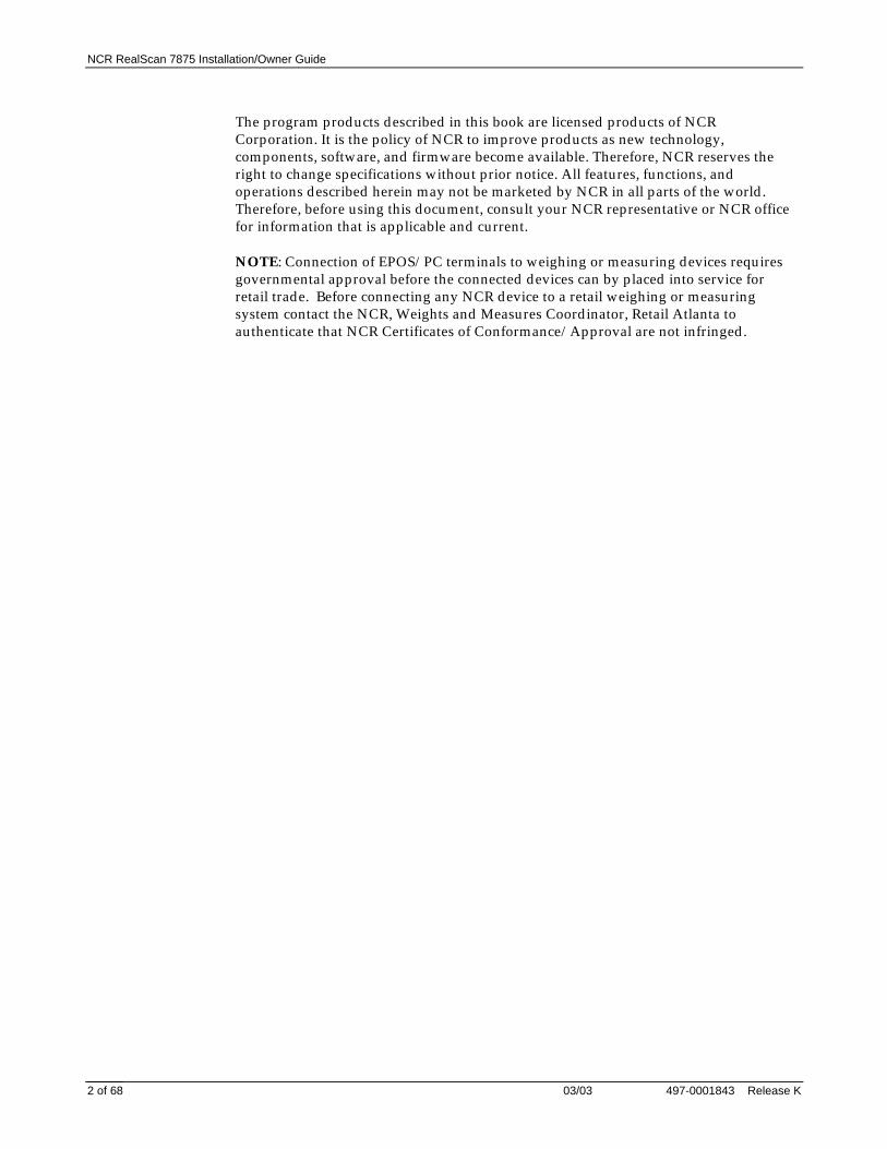
Checkstand Cutout –RealScan 7875-7000/8000
20551
GD D
H
I
A
B
E
C
C
D
A B C D E
11 5/8 in.29.51 cm
20 1/16 in.50.95 cm
1 3/8 in.3.49 cm
3/8 in.0.95 cm
17 5/16 in.43.97 cm
7875-7200Scanner
12 1/16 in.30.63 cm
20 1/16 in.50.95 cm
1 3/8 in.3.49 cm
1/2 in.1.27 cm
17 5/16 in.43.97 cm
7875-8200Scanner/Scale
7875-7200Scanner
7875-8200Scanner/Scale
F G1 3/8 in.3.49 cm
7 1/8 in.18.1 cm
1 3/8 in.3.49 cm
7 1/8 in.18.1 cm
H I7 1/8 in.
18.10 cm7 1/4 in.
18.42 cm
7 in.17.78 cm
7 1/4 in.18.42 cm
Note: Dimension A for a 7875-7200 includes a spacer along each side of the unit so that it fits an existing 7870-2000 cutout.
Recommended shelf to catchRealScan 7875 if dropped during installation.
*
No electronics under RealScan 7875
C C
B
EF
A
F*

NCR RealScan 7875 Installation/Owner Guide
497-0001843 Release K 03/03 13 of 68
Display Clarence
30
This area must be clearfor viewing optionalintegrated display. 60
50
60
14954
Service Clearance
A = 8.0 in. (20.3 cm) minimum if checkstand structure is not removable for servicing. 1.0 in. (2.5 cm) minimum if checkstand structure is removable for servicing.B = 14.0 in. (35.6 cm) minimum if checkstand structure is not removable for servicing. 7.0 in. (17.8 cm) minimum if checkstand structure is removable for servicing.C = 5.1in. (13.0 cm) minimum clearance to closest checkstand panel. The 7875-1000/2000/4005 must not be supported by this panel.
A A
C
B
Mounting surface for keyboard mustbe removable for servicing andvertical window replacement.
Item Flow Area
All Installations Installations Without An Integrated Display
14955

NCR RealScan 7875 Installation/Owner Guide
03/03 497-0001843 Release K14 of 68
Item Diverter
Item Diverter(Must be removable to service Scanner/Scale in checkstand)
7.25 in. (18.4 cm)
14957
Ventilation RequirementsThe RealScan 7875 is designed to operate without an exhaust fan in the checkstand;however, there must be adequate convection airflow. The ambient temperature insidethe checkstand cannot be higher than 40° C (104° F). Also, the ambient temperatureinside the checkstand cannot be higher than 7° C (12.6° F) above the ambienttemperature outside the checkstand. For example, if the ambient temperature outsidethe checkstand is 24.4° C (76° F), the ambient temperature inside the checkstand cannotbe greater than 31.4° C (88.6° F). If the checkstand contains other heat producingequipment, you may need to use forced air to keep the temperature within the specifiedrange. However, air coming into or leaving the checkstand MUST NOT enter or exitpast the RealScan 7875.

NCR RealScan 7875 Installation/Owner Guide
497-0001843 Release K 03/03 15 of 68
Electrical Wiring to the Checkstand
Feeder wiring and insulated ground frommain service panel to distribution panelto be run in metal conduit.
The electrical wiring must meet allelectrical codes, laws, and regulations.
Note:
Circuit Breakers
NCR circuits should be run inseparate metal Conduits.
Isolated/InsulatedGround Bus
Isolated Ground Receptacles
Neutral andGround Bus
NeutralBus
InputVoltage
Input Voltage L1, L2 Circuit BreakersU.S., Canada, &Japan
European
International
100Vac to 120Vac
220Vac
220Vac to 240Vac
100Vac to 120Vac
220Vac
220Vac to 240Vac
Standard single-pole; valuedetermined by type of devicebranch and by electrical code.
European double-pole.
Circuit B: Terminal
Installation Type
NCR circuits must be dedicated toNCR equipment or other logicallyconnected electronic equipment(modems, DAA, bridges, etc.)
Note:
Circuit C: Scanner/ScaleReceptacle should be easilyaccessible and near theScanner/Scale
L2
L3
Distribution Panel
Main ServicePanel
Conduit
CheckstandFrame
Circuit A: Checkstand
BeltMotor
Belt ControlLighting
Misc. Equip.N
G
L1
R0121
Note: The RealScan 7875 outlet in the checkstand must be connected to a circuit breakerswitch. This switch must be located close to the operator and is used as the On/Offswitch for the RealScan 7875.

NCR RealScan 7875 Installation/Owner Guide
03/03 497-0001843 Release K16 of 68
Hole Requirements for CablesWhen you run the various cables through the checkstand, you might have to drill holesin some of the panels. The holes must be large enough for the connector on one end ofthe cable to pass through. You must also ensure that there are no sharp edges to cut thecable. The following table gives the minimum hole size for each of the RealScan 7875cables.
Cable Cable Length Minimum Hole SizePower Cord – Outlet to PowerSupply
3.05 meters (10 feet) 3.18 centimeters (3/4 inch)
Power Cord – Power Supply toRealScan 7875
1.22 meters (4 feet) 1.52 centimeters (1/2 inch)
Interface Cable 8.0 meters (26.24 feet) 1.90 centimeters (3/4 inch)4.0 meters (12.12 feet) 1.90 centimeters (3/4 inch)
Remote Display Cable 8.0 meters (26.24 feet) 1.90 centimeters (3/4 inch)4.0 meters (12.12 feet) 1.90 centimeters (3/4 inch)
NCR RealScan 7875 Installation/Owner Guide
497-0001843 Release K 03/03 17 of 68
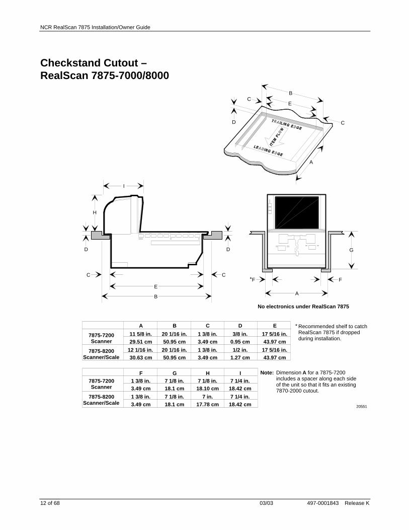
Step 2 – Connect the Cables
There are several cables associated with the RealScan 7875, some are required withevery installation and some are optional, depending on the system. Check to make surethat you have all the necessary cables for your installation. Connect the cables accordingto one of the following illustrations.
Note: If the RealScan 7875 contains the Checkpoint feature, you need to have aCheckpoint representative connect the cable to their equipment.
Single Cable Installation
14958
DCPower Cable
RemoteDisplay
ACPowerCord
PowerSupply RealScan 7875
InterfaceCable
HostTerminal
PORT 1 PORT 2
DUAL PERIPHERAL PORTS
RS-232Peripheral
DC
PO
WE
R
RE
MO
TE
DIS
PL
AY
5A M
AX
SC
AN
NE
R
Check switch settings
5V
Or
DC
PO
WE
R
RE
MO
TE
DIS
PL
AY
5A M
AX
SC
AN
NE
R
US
B
5V
RS
-232
IBM
-RS
-485

NCR RealScan 7875 Installation/Owner Guide
03/03 497-0001843 Release K18 of 68
Dual Cable Installation
20594
DCPower Cable
RemoteDisplay
ACPowerCord
PowerSupply RealScan 7875
ScaleInterfaceCable
HostTerminal
RS-232Peripheral
DC
PO
WE
R
RE
MO
TE
DIS
PL
AY
5A M
AX
SC
AN
NE
R
AU
X P
OR
T/
DA
TA
CH
KR
Check switch settings
5V
ScannerInterfaceCable
PORT 1 PORT 2
DUAL PERIPHERAL PORTS

NCR RealScan 7875 Installation/Owner Guide
497-0001843 Release K 03/03 19 of 68
RealScan 7875-7000/8000
BCAN I/O POS SERVICE REMOTE ANTENNAEXPANSIONBR
MNS
PROGSTATUS
20553
DC
PO
WE
R
RE
MO
TE
DIS
PL
AY
5A M
AX
SC
AN
NE
R
Check switch settings
5V
DCPower Cable
RemoteDisplay
ACPowerCord
PowerSupply RealScan 7875
InterfaceCable
HostTerminal
RS-232Peripheral
PORT 1 PORT 2
DUAL PERIPHERAL PORTS
SensormaticScanMax™ Pro Controller
SensormaticInterlock Cable
SensormaticAntennaCable
AC PowerCord

NCR RealScan 7875 Installation/Owner Guide
03/03 497-0001843 Release K20 of 68
Bizerba Scale Installation
19318
DCPower Cable
ACPowerCord
PowerSupply RealScan 7875
ScaleCable
HostTerminal
BizerbaDisplay
kg T kg Preis/kg Preis
InterfaceCable
DC
PO
WE
R
RE
MO
TE
DIS
PL
AY
5A M
AX
SC
AN
NE
R
US
B
5V
RS
-232
IBM
-RS
-485
Or
DC
PO
WE
R
RE
MO
TE
DIS
PL
AY
5A M
AX
SC
AN
NE
R
Check switch settings
5V

NCR RealScan 7875 Installation/Owner Guide
497-0001843 Release K 03/03 21 of 68
Sensormatic Antenna
20574
Sensormatic Antenna Cable
Sensormatic Antenna
Note: The Sensormatic Antenna is very heavy; do not to drop it in the scanner.
The Sensormatic Antenna can be positioned on either side of the RealScan 7875. Itshould always be placed on the trailing side. If the installation is setup to scan fromright to left, put the Sensormatic Antenna on the left side of the scanner.
1. Feed the Sensormatic Antenna Cable through the large hole in the front of theMounting Bracket (bucket). This must be the hole on the side where you areinstalling the antenna.
2. Carefully place the Sensormatic Antenna in position, setting it on the Sub Plate.3. Route the Sensormatic Antenna Cable down through the slot in the front of the
Mounting Bracket (bucket).4. Connect the Sensormatic Antenna Cable and Sensormatic Interlock Cable.
20592
RealScan 7875
SensormaticInterlock Cable
SensormaticAntennaCable
ScanMax™ Pro Controller
ACPowerCord
BCAN I/O POS SERVICE REMOTE ANTENNAEXPANSIONBR
MNS
PROGSTATUS
Back Front

NCR RealScan 7875 Installation/Owner Guide
03/03 497-0001843 Release K22 of 68
RS-232 Peripheral CablesThe cable on some RS-232 hand-held peripheral devices is not long enough to connect tothe RealScan 7875 (under the checkstand) and still permit easy use of the device. Inthese cases, NCR recommends that you install an extension cable. You can obtain onefrom NCR (Corporate ID Number 1416-C313-0040) or you can make your own. If youmake your own, it should be approximately 39 inches (1 meter) long with 8-pin phonetype connectors on each end.
J1 P1
16046
12345678
12345678
12345678
J1 Wire Number P11
8
1
8
Power Supply LocationLocate the Power Supply in a convenient place inside the checkstand. It must be closeenough for the Power Cable to reach the RealScan 7875. However, do not place thePower Supply where spilled liquids can run down onto it.

NCR RealScan 7875 Installation/Owner Guide
497-0001843 Release K 03/03 23 of 68
Step 3 – Install RealScan 7875 inCheckstand
Set the Communications Protocol SwitchNote: RealScan 7875 Super ASIC models do not have Communications ProtocolSwitches. Continue on to the next task.
Before setting the RealScan 7875 into the cutout in the checkstand, verify that theCommunications Protocol Switch is properly set. Single cable units have one switch,dual cable units have two. The switches are located on the Interface Board and you canaccess them through holes in the side of the unit. For RS-232 communications, bothswitches must be toward the front (operator side) of the unit. For all othercommunication protocols, both switches must be toward the back (customer side) of theunit.
14960
AUX PORT/DATACHKR
SCANNER
DATACHKR OCIA/IBM
RS-232 RS-232
Make sure power isoff before changingswitch setting
Switches

NCR RealScan 7875 Installation/Owner Guide
03/03 497-0001843 Release K24 of 68
Installing the RealScan 7875 into the Checkstand CutoutGrasp the RealScan 7875 as shown and lower it into the checkstand cutout. Be carefulnot to damage any of the cables. After the unit is properly sitting on its supports, installthe Top Plate.
Note: It is important that the RealScan 7875 does not rock on its supports. Make surethat all adjustable supports are securely fastened and that the RealScan 7875 is sitting onall supports.
15184A15184B
Align the RealScan 7875 to the CheckstandThe leading edge of the Top Plate must be flush or up to 1/16 in. (0.15 cm) below thetop of the checkstand. The trailing edge of the Top Plate must be flush or up to 1/16 in.(0.15 cm) above the top of the checkstand.
Note: The four adjustable support posts on the Scale Hinge Assembly are set at thefactory. Do not attempt to adjust the Top Plate using these posts. Adjust theRealScan 7875 supports to align the Top Plate with the checkstand.
If the Top Plate is properly aligned with the checkstand, an item should easily slidefrom the checkstand onto the Top Plate and then from the Top Plate onto thecheckstand. The following illustration shows this alignment.

NCR RealScan 7875 Installation/Owner Guide
497-0001843 Release K 03/03 25 of 68
14961
Correct Alignment
Bad AlignmentScanner Too High
Bad AlignmentScanner Too Low
High SurfaceLow SurfaceHigh SurfaceLow Surface
Set Scale AC Voltage FrequencyThe RealScan 7875-2000/8000 units contain a scale that must be set for the correct ACvoltage frequency before the scale is calibrated.
1. Turn on the AC Power by turning on the circuit breaker.2. Set the AC voltage frequency by scanning the following sequence of programming
tags. These must be the first tags scanned after applying power to the unit.
60 Hz AC Voltage Programming Mode, Hex 3, Hex 0, Hex F – Default setting50 Hz AC Voltage Programming Mode, Hex 3, Hex 0, Hex E
3. Calibrate the scale by going to Step 4 – Calibrate the Scale.
NCR RealScan 7875 Installation/Owner Guide
03/03 497-0001843 Release K26 of 68
Step 4 – Calibrate the Scale
If you are not installing a RealScan 7875-2000/8000, do not perform this step but godirectly to Step 5 – Set the Program Parameters.
Note: The Bizerba computing scale, used in a RealScan 7875-4000, is calibrated at thefactory and cannot be calibrated in the field. However, you can reset the scale byturning off the power, then turning it back on with no weight on the Top Plate. If youare installing a RealScan 7875-4000 with a Bizerba scale do not attempt to calibrate thescale, but continue to Step 5 – Check the Scanner Operation.
Note: You MUST calibrate the scale when you install a RealScan 7875-2000/8000. To bein compliance with governmental weights and measures regulations, you must becertified to calibrate the scale.
Note: Calibration information is NOT sent to the host terminal. If your RealScan 7875does not have voice enabled or does not have a remote display, you must use a FieldService Calibration Display.
Note: Be sure the Interface Cable between the RealScan 7875 and the host terminal isdisconnected during scale calibration. Some host terminals can cause interference thatcan invalidate the scale calibration.
You can calibrate the scale after power has been supplied for 30 minutes if the ambienttemperature has been 20° C (68° F) for at least 24 hours. If this condition is not met, thenthe scale must be on for at least 6 hours before you can calibrate it. Also, you must use acertified weight set to calibrate and certify the scale.
The RealScan 7875 maintains an audit trail of scale calibration and programmingactivity. The audit trail records the number of times the scale has been calibrated. Youcan display the audit trail count on a Remote 7825 or Field Service Calibration Displayby pressing the Scale Zero Button on the Operator Display Panel. The display alternatesbetween Cal xxx and PAr xxx.
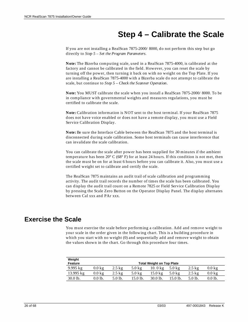
Exercise the ScaleYou must exercise the scale before performing a calibration. Add and remove weight toyour scale in the order given in the following chart. This is a building procedure inwhich you start with no weight (0) and sequentially add and remove weight to obtainthe values shown in the chart. Go through this procedure four times.
WeightFeature Total Weight on Top Plate9.995 kg 0.0 kg 2.5 kg 5.0 kg 10. 0 kg 5.0 kg 2.5 kg 0.0 kg13.995 kg 0.0 kg 2.5 kg 5.0 kg 15.0 kg 5.0 kg 2.5 kg 0.0 kg30.0 lb. 0.0 lb. 5.0 lb. 15.0 lb. 30.0 lb. 15.0 lb. 5.0 lb. 0.0 lb.

NCR RealScan 7875 Installation/Owner Guide
497-0001843 Release K 03/03 27 of 68
Access the Calibration SwitchThe Calibration Switch is located below the Top Plate. Remove the Top Plate.
RealScan 2000
If your RealScan 7875-2000 has a Produce Guard, it must be removed to access theCalibration Switch Cover. Lift the Cover up to remove.
Calibration Switch Cover
14962
Remove the screw that secures the Calibration Switch Security Cover. Also remove theseal if one is present. Rotate the Calibration Switch Cover to gain access to theCalibration Switch.
Calibration SwitchSecurity Cover
Screw
Wire Seal
Calibration Switch
16047

NCR RealScan 7875 Installation/Owner Guide
03/03 497-0001843 Release K28 of 68
RealScan 7875-8000
The RealScan 7875-8000 does not have a plastic Calibration Switch Cover. Do notremove the Produce Guard if one is present.
Remove the screw that secures the Calibration Switch Security Cover. Also remove theseal if one is present. Rotate the Calibration Switch Cover to gain access to theCalibration Switch.
Screw
Wire Seal
Calibration SwitchSecurity Cover
20587
Calibration Switch

NCR RealScan 7875 Installation/Owner Guide
497-0001843 Release K 03/03 29 of 68
Calibrate the Scale1. Press the Scale Zero Button to display the Cal and PAr values. Record these values.2. Install the Produce Guard if one is included then install the Top Plate. Raise the
front edge of the Top Plate enough to access the Calibration Switch and press it,then quickly lower the Top Plate. The display should show Ready C-00 kg (00 lb.).
3. Follow the sequence of steps in the following chart.
Display Add Weight Remove WeightReady C-2.5 kg (05 lb.) 2.50 kg (5.00 lb.)Ready C-05 kg (15 lb.) 2.50 kg (10.00 lb.)Ready C-10 kg (30 lb.) 5.00 kg (15.00 lb.)Ready C-00 kg (00 lb.) 10.00 kg (30.00 lb.)Ready 0.000 kg (0.00 lb.)
Verify the CalibrationThe scale accuracy test meets government requirements of testing the accuracy of thescale after performing a scale calibration. It contains a series of four tests that must berun in the continuous sequence given.
Increasing Load Test
This test checks the scale’s accuracy when incrementally adding weight to the center ofthe top plate. Use weights that correspond to the RealScan 7875 weight feature.
Step Weight Feature Add Weight Remove Weight Display Result1 9.995 kg 0.1 kg 0.1 ± 0.00 kg
13.995 kg 0.1 kg 0.1 ± 0.00 kg30.0 lb. 0.2 lb. 0.2 ± 0.00 lb.
2 9.995 kg 2.5 kg 0.1 kg 2.5 ± 0.00 kg13.995 kg 2.5 kg 0.1 kg 2.5 ± 0.00 kg30.0 lb. 5.0 lb. 0.2 lb. 5.0 ± 0.00 lb.
3 9.995 kg 2.5 kg 5.0 ± 0.005 kg13.995 kg 4.5 kg 7.0 ± 0.005 kg30.0 lb. 5.0 lb. 10.0 ± 0.01 lb.
4 9.995 kg 2.5 kg 7.5 ± 0.005 kg13.995 kg 3.0 kg 10.0 ± 0.005 kg30.0 lb. 10.0 lb. 20.0 ± 0.01 lb.
5 9.995 kg 2.495 kg 9.995 ± 0.005 kg13.995 kg 3.995 kg 13.995 ± 0.005 kg30.0 lb. 10.0 lb. 30.0 ± 0.01 lb.
Note: Do NOT remove any weight from the Top Plate.
NCR RealScan 7875 Installation/Owner Guide
03/03 497-0001843 Release K30 of 68
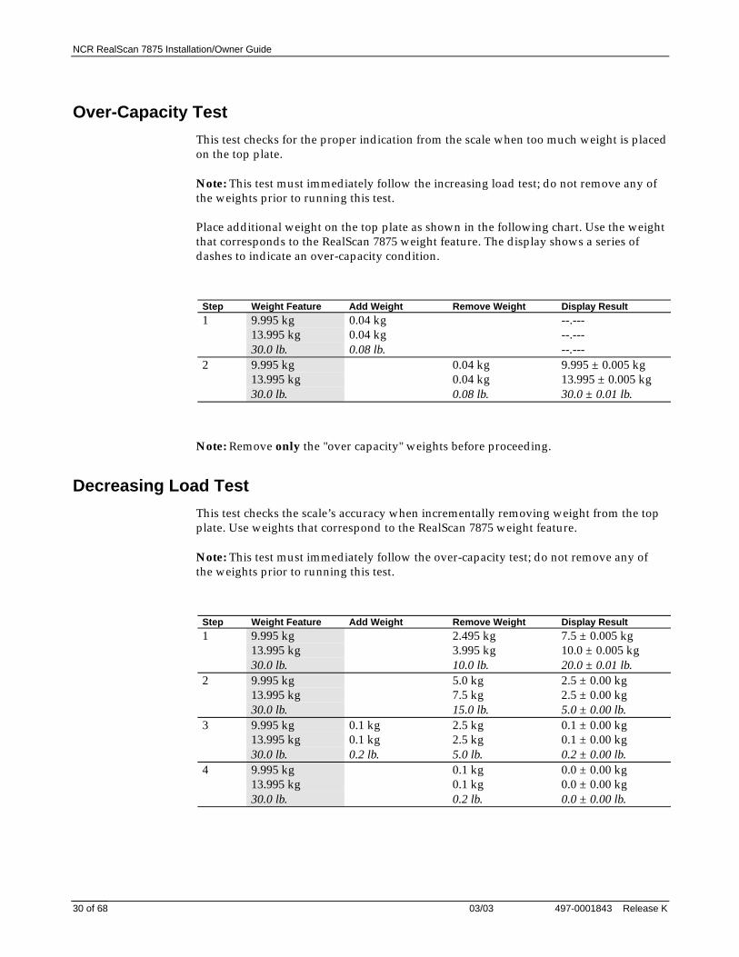
Over-Capacity Test
This test checks for the proper indication from the scale when too much weight is placedon the top plate.
Note: This test must immediately follow the increasing load test; do not remove any ofthe weights prior to running this test.
Place additional weight on the top plate as shown in the following chart. Use the weightthat corresponds to the RealScan 7875 weight feature. The display shows a series ofdashes to indicate an over-capacity condition.
Step Weight Feature Add Weight Remove Weight Display Result1 9.995 kg 0.04 kg --.---
13.995 kg 0.04 kg --.---30.0 lb. 0.08 lb. --.---
2 9.995 kg 0.04 kg 9.995 ± 0.005 kg13.995 kg 0.04 kg 13.995 ± 0.005 kg30.0 lb. 0.08 lb. 30.0 ± 0.01 lb.
Note: Remove only the "over capacity" weights before proceeding.
Decreasing Load Test
This test checks the scale’s accuracy when incrementally removing weight from the topplate. Use weights that correspond to the RealScan 7875 weight feature.
Note: This test must immediately follow the over-capacity test; do not remove any ofthe weights prior to running this test.
Step Weight Feature Add Weight Remove Weight Display Result1 9.995 kg 2.495 kg 7.5 ± 0.005 kg
13.995 kg 3.995 kg 10.0 ± 0.005 kg30.0 lb. 10.0 lb. 20.0 ± 0.01 lb.
2 9.995 kg 5.0 kg 2.5 ± 0.00 kg13.995 kg 7.5 kg 2.5 ± 0.00 kg30.0 lb. 15.0 lb. 5.0 ± 0.00 lb.
3 9.995 kg 0.1 kg 2.5 kg 0.1 ± 0.00 kg13.995 kg 0.1 kg 2.5 kg 0.1 ± 0.00 kg30.0 lb. 0.2 lb. 5.0 lb. 0.2 ± 0.00 lb.
4 9.995 kg 0.1 kg 0.0 ± 0.00 kg13.995 kg 0.1 kg 0.0 ± 0.00 kg30.0 lb. 0.2 lb. 0.0 ± 0.00 lb.

NCR RealScan 7875 Installation/Owner Guide
497-0001843 Release K 03/03 31 of 68
Shift Test
This test involves moving a weight off the center point of the top plate to check forcontinued accuracy.
1. Place 5.00 kg (15.00 lb.) of weight in position 1 on the Top Plate.2. Move the weight to position 2 on the Top Plate. The display should show 5.00 ±
0.005 kg (15.00 ± 0.01 lb.).3. Repeat step 2 for positions 3, 4, and 5.4. Move the weight to position 1 again.5. Remove all weights. The display should read 0.000 ± 0.000kg (0.00 ± 0.00 lb.).6. Press the Scale Zero Button. Record the Cal and PAr values shown on the display.
14967
1
2
34
5
Secure the Calibration SwitchRemove the Top Plate. If the unit is a RealScan 7875-2000, remove the Produce Guard, ifincluded. Rotate the Calibration Switch Security Cover into position and install thescrew.
When you perform a scale calibration, someone must seal the Calibration SwitchSecurity Cover. This may be done with a Lead/Wire Seal (NCR part number603-8001097) using a Lead/Wire Seal Press (NCR part number 603-9000157) or aFilm/Paper seal (obtained locally). The type of seal you use depends on your local laws;also, Weights and Measures officials may be required to attach the seal.
NOTE: In the United States and Canada, the audit trail can serve as an acceptablesecurity seal if an NCR 7825 Display is used as the weight display.
After securing the Calibration Switch, if the unit is a RealScan 7875-2000, install theplastic Calibration Switch Cover and the Produce Guard if included. Install the TopPlate.

NCR RealScan 7875 Installation/Owner Guide
03/03 497-0001843 Release K32 of 68
Step 5 – Set Program Parameters
Now you need to make any necessary programming changes to the RealScan 7875. TheRealScan 7875 does not have an On/Off switch. Use the circuit breaker switch in thecheckstand that supplies power to the unit as the On/Off switch.
Setting the Program ParametersCaution: Some host terminals can corrupt the RealScan 7875 program if they arerunning and are connected to the RealScan 7875 while you are making programchanges. Either turn off the host terminal or disconnect the interface cable beforescanning any programming tags.
To make changes to the program parameters, enter information from the ProgrammingWorksheets located toward the back of this book. The Programming Worksheetsidentify all the available program parameters. Each worksheet relates to a specificprogramming mode. Most programming options have defaults, identified by a heavybox, which are determined at the factory. Scanning the Default tag as the first tag afterapplying power to the unit sets the parameters to these values.
Changing the RealScan 7875 program is accomplished by scanning the proper sequenceof programming tags. Following are three major steps for making program changes.
1. Enter the Base Programming State by scanning the Programming Mode tag; mustbe first tag scanned after applying power.
2. Select a Programming Worksheet and enter its parameter data by scanning theappropriate Hex tags.
3. Save the program by scanning the Save and Reset tag.
Note: In most cases the factory determined defaults are the correct parameter setting.However, if you do need to make changes, it is recommended that you first set allparameters to default values then make any necessary changes to the appropriateparameters.

NCR RealScan 7875 Installation/Owner Guide
497-0001843 Release K 03/03 33 of 68
Determining the Communication ProtocolDetermine the communications protocol with the following procedure.
1. Apply power to the RealScan 7875.2. Scan the Diagnostic Mode tag; must be the first tag scanned after applying power.
Scan the Hex 3 tag. The good read tone for this tag sounds (three beeps).
If the Voice feature enabled, the communications protocol is given audibly. If Voiceis not enabled, the Status indicator flashes green and the tone beeps a specificnumber of times to identify the communication protocol.
1 Short, high-pitched beepOCIA NCR Short
1 BeepOCIA NCR Long
2 BeepsOCIA Non-NCR Dual Cable
3 BeepsIBM 468x Port 4A
4 BeepsIBM 468x Port 4B (HHBCR)
6 BeepsRS-232
7 BeepsOCIA Single-Cable
8 BeepsOCIA Dual-Cable
11 BeepsCasio 4-Bit Parallel Dual Cable
12 BeepsIBM 1520 (BCR)
13 BeepsTEC 4-Bit Parallel Dual Cable
3. Remove power from the RealScan 7875.
NCR RealScan 7875 Installation/Owner Guide
03/03 497-0001843 Release K34 of 68
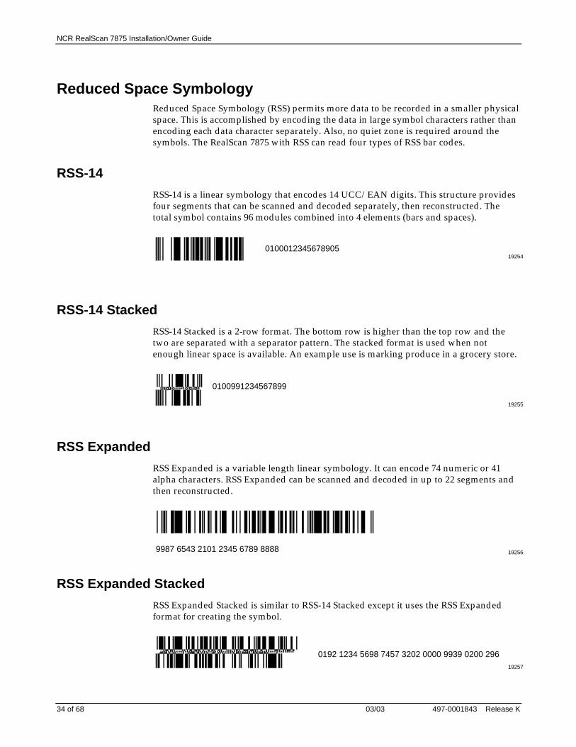
Reduced Space SymbologyReduced Space Symbology (RSS) permits more data to be recorded in a smaller physicalspace. This is accomplished by encoding the data in large symbol characters rather thanencoding each data character separately. Also, no quiet zone is required around thesymbols. The RealScan 7875 with RSS can read four types of RSS bar codes.
RSS-14
RSS-14 is a linear symbology that encodes 14 UCC/EAN digits. This structure providesfour segments that can be scanned and decoded separately, then reconstructed. Thetotal symbol contains 96 modules combined into 4 elements (bars and spaces).
192540100012345678905
RSS-14 Stacked
RSS-14 Stacked is a 2-row format. The bottom row is higher than the top row and thetwo are separated with a separator pattern. The stacked format is used when notenough linear space is available. An example use is marking produce in a grocery store.
19255
0100991234567899
RSS Expanded
RSS Expanded is a variable length linear symbology. It can encode 74 numeric or 41alpha characters. RSS Expanded can be scanned and decoded in up to 22 segments andthen reconstructed.
192569987 6543 2101 2345 6789 8888
RSS Expanded Stacked
RSS Expanded Stacked is similar to RSS-14 Stacked except it uses the RSS Expandedformat for creating the symbol.
19257
0192 1234 5698 7457 3202 0000 9939 0200 296

NCR RealScan 7875 Installation/Owner Guide
497-0001843 Release K 03/03 35 of 68
Enabling RSS
Enable the Reduced Space Symbology feature by scanning the following sequence ofprogramming tags. These must be the first tags scanned after applying power to theunit.
1. Programming Mode – Puts the RealScan 7875 in the Programming Mode2. Hex 1, Hex 8, Hex A, Hex 3 – Enables RSS-14 and RSS Expanded.3. Save and Reset – Saves the parameter setting.
Disabling RSS
Disable the Reduced Space Symbology feature by scanning the following sequence ofprogramming tags. These must be the first tags scanned after applying power to theunit.
1. Programming Mode – Puts the RealScan 7875 in the Programming Mode.2. Hex 1, Hex 8, Hex A, Hex 0 – Disables RSS feature.3. Save and Reset – Saves the parameter setting.

NCR RealScan 7875 Installation/Owner Guide
03/03 497-0001843 Release K36 of 68
Sensormatic Deactivation SystemNote: Refer to the Sensormatic ScanMax™ Pro Controller documentation forinformation about setting up the controller.
When the RealScan 7875 is first turned on, all the Sensormatic parameters should be attheir default settings. Use the following procedure to program the system and make itoperational.
1. Scan the Restore Sensormatic Parameters tag. The security tag deactivationfunction must be disabled (default).• Security tag deactivation function is enabled.• Security tag deactivated tone is enabled.• Security tag deactivated tone is set to a single long tone.• Security tag detected tone is enabled.• All other necessary parameters in the RealScan 7875 are set to default values.• The RealScan 7875 checks the parameters set in the Sensormatic ScanMax™ Pro
Controller. If the parameters are set to match the RealScan 7875 defaults, theRealScan 7875 generates the voice message EAS Online, otherwise the RealScan7875 generates the voice message EAS Online Mode One.
2. Two options are available if the EAS Online Mode One message is given:download the RealScan 7875 parameter defaults to the ScanMax™ Pro Controller ormake necessary changes directly to the ScanMax™ Pro Controller.
Download 7875 Parameters to ScanMax™ Pro Controller
To use the RealScan 7875 parameter defaults, scan the Restore Sensormatic Parameterstag. This downloads the default parameters to the ScanMax™ Pro Controller.
Set ScanMax™ Pro Controller Parameters at the Controller
If the RealScan 7875 default parameters are not exactly what are needed, you can makechanges directly to the ScanMax™ Pro Controller. Refer to the Sensormatic ScanMax™Pro Controller documentation.
1. Make all the necessary changes to the ScanMax™ Pro Controller according to theSensormatic documentation.
2. Scan the Reset tag and listen for Change in Parameters.3. Scan the Save Sensormatic Parameters tag. This sets the RealScan 7875 parameter
defaults to those set in the ScanMax™ Pro Controller.
Should the ScanMax™ Pro Controller lose its settings or be replaced, scan theRestore Sensormatic Parameters tag and restore the parameters at the controller.
Note: Scanning the Save Sensormatic Parameters tag enables soft defaults in theRealScan 7875 and sets them to the ScanMax™ Pro Controller values. To permit theDefault tag to restore parameters to the factory defined values, disable the soft defaultfunction by scanning the following sequence of programming tags.
Programming Mode, Hex 3, Hex 4, Hex 0, Save and Reset.

NCR RealScan 7875 Installation/Owner Guide
497-0001843 Release K 03/03 37 of 68
Specific Function Programming
There are several Sensormatic Security Tag Deactivation functions that can beprogrammed separately. These parameters are also set when the Restore SensormaticParameters tag is scanned. Refer to step 1 in Sensormatic Deactivation System.
Security Tag Deactivation
This parameter enables or disables the entire Sensormatic Deactivation function.
Enable Security Tag DeactivationProgramming Mode, Hex 4, Hex 2, Hex B, Save and Reset.
Disable Security Tag DeactivationProgramming Mode, Hex 4, Hex 2, Hex A, Save and Reset.
Security Tag Detected Tone
This parameter enables or disables a tone while a security tag is being detected. Whenenabled and a security tag is within the detection zone, a continuous beeping tone isproduced that sounds similar to a Geiger counter.
Enable Security Tag Detected ToneProgramming Mode, Hex 6, Hex 2, Hex D, Save and Reset.
Disable Security Tag Detected ToneProgramming Mode, Hex 6, Hex 2, Hex C, Save and Reset.
Deactivated Tone
This parameter enables or disables a tone following a security tag deactivation.
Enable Security Tag Deactivated ToneProgramming Mode, Hex 4, Hex B, Hex B, Save and Reset.
Disable Security Tag Deactivated ToneProgramming Mode, Hex 4, Hex B, Hex A, Save and Reset.
Deactivated Tone Type
This parameter determines the type of tone to produce when a security tag isdeactivated.
Series of TonesProgramming Mode, Hex 4, Hex B, Hex E, Save and Reset.
Single Long ToneProgramming Mode, Hex 4, Hex B, Hex F, Save and Reset.
Deactivated Tone Frequency and Length
The Deactivated Tone frequency and length can be adjusted by scanning theappropriate tags. Each time you scan the Deactivated Tone Frequency tag the tonefrequency increases until it reaches a maximum level. At this point the cycle continuesfrom the lowest level. Each time you scan the Deactivated Tone Length tag the tonelength increases until it reaches a maximum time. At this point the cycle continues fromthe shortest time.
NCR RealScan 7875 Installation/Owner Guide
03/03 497-0001843 Release K38 of 68
Step 6 – Check the ScannerOperation
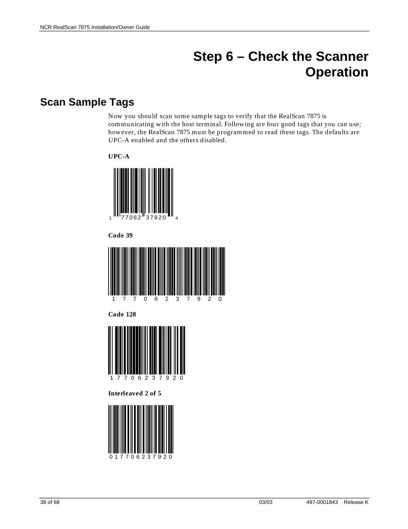
Scan Sample TagsNow you should scan some sample tags to verify that the RealScan 7875 iscommunicating with the host terminal. Following are four good tags that you can use;however, the RealScan 7875 must be programmed to read these tags. The defaults areUPC-A enabled and the others disabled.
UPC-A
1 7 7 0 6 2 3 7 9 2 0 4
Code 39
1 7 7 0 6 2 3 7 9 2 0
Code 128
1 7 7 0 6 2 3 7 9 2 0
Interleaved 2 of 5
0 1 7 7 0 6 2 3 7 9 2 0

NCR RealScan 7875 Installation/Owner Guide
497-0001843 Release K 03/03 39 of 68
Check Sensormatic Deactivation SystemIf you installed a RealScan 7875-7000/8000 with the Sensormatic Deactivation System,check out the deactivation function. Obtain a security tag. Scan a bar code and withintwo seconds pass the security tag through the deactivation zone. The Deactivated Toneshould sound if it is enabled. Refer to the Operating the Sensormatic Deactivation Systemsection for detailed operating instructions.

NCR RealScan 7875 Installation/Owner Guide
03/03 497-0001843 Release K40 of 68
Operating the Scanner
The RealScan 7875 is a fixed position device that is installed in a checkout counter. It isnot handled or moved by the operator during operation. The RealScan 7875 ismaintained and serviced by trained service personnel only. The operator has no accessto any laser module components.
The RealScan 7875 does not have a power switch. However, you turn it on and off byusing the circuit breaker switch, located in the checkstand, that supplies power to theunit. Be sure this switch is in the On position.
The Status Indicator on the Operator Display Panel is Red when the RealScan 7875 isready. The correct way to scan is to slide an item from the checkstand, across thescanner, and back onto the checkstand. With a good scan, the Status Indicator FlashesGreen, then turns Red. Nothing happens if the bar code is not read.
14966
Status Indicator

NCR RealScan 7875 Installation/Owner Guide
497-0001843 Release K 03/03 41 of 68
Operating the Scale
The RealScan 7875 typically takes from 1.0 to 2.0 seconds to weigh an item, dependingon the item’s weight. The heavier the item, the longer it takes. Before weighing an item,make sure the scale display is displaying all zeros. If not, press the Scale Zero Button.
Note: The item you are weighing should be placed in the center of the Top Plate. Makesure the item does not overhang onto the checkstand; whatever is weighed must fit fullyon the Top Plate. If the RealScan 7875 includes the Produce Guard, larger items may restagainst it.
When the scale weighs an item, the Status Indicator flashes Green and a good weightone is sounded. Nothing happens if the scale cannot weigh an item.
Status Indicator
Scale Zero Button
Integrated Display
16048
Top Plate
Note: If you have a RealScan 7875-4000 with a Bizerba scale, refer to the Bizerbadocument for additional scale operating procedures if needed.

NCR RealScan 7875 Installation/Owner Guide
03/03 497-0001843 Release K42 of 68
Operating the SensormaticDeactivation System
Normal OperationThe operating procedures can vary according to the parameter settings. The followingprocedure assumes the Sensormatic parameters are set to the following values.
• Security tag deactivation function is enabled.• Security tag deactivated tone is enabled.• Security tag deactivated tone is set to a single long tone.• Security tag detected tone is enabled.
Following procedure assumes the RealScan 7875 and the Sensormatic ScanMax™ ProController are turned on and functioning properly.
1. Pass an item across the scanner.2. As the bar code goes through the scan zone, the RealScan 7875 reads it and sounds a
Good Read tone.3. As the security tag goes through the Sensormatic deactivation zone, the Sensormatic
system deactivates the security tag and a Security Tag Deactivated tone sounds.This normally happens fast enough that the Security Tag Detected Tone does notsound.
Note: The security tag must be detected by the Sensormatic system with twoseconds after the RealScan 7875 reads the bar code. If more than two seconds elapse,the security tag is not deactivated even when it does come into the deactivationzone. In this case, the Security Tag Detected Tone sounds while the tag is in thedeactivation zone. The sound is similar to a Geiger counter. When this conditionoccurs, the security tag must be deactivated manually.
Manual DeactivationIf for some reason the security tag is not deactivated in the normal manner, it can bedeactivated manually. This normally occurs when too much time elapses after theRealScan 7875 reads the barcode. There are two ways to initiate a manual security tagdeactivation.
1. Press the Volume button on the RealScan 7875 or scan the Manual Deactivation tag.The RealScan 7875 laser light and spinner motor turn off, disabling the scanner.
2. Pass the security tag into the deactivation zone. The Security Tag Detected Tonesounds (similar to a Geiger counter) and the tag is deactivated. The RealScan 7875laser light and spinner motor turn on, enabling the scanner.

NCR RealScan 7875 Installation/Owner Guide
497-0001843 Release K 03/03 43 of 68
Cleaning the RealScan 7875
Keeping the scan windows clean helps keep the read rate exceptionally high. Duringnormal operation the scan windows get dirty, and if you permit the dirt to accumulate,performance degrades to the point where the scanner cannot read bar codes. The PleaseClean Window indicator flashes when the scan windows need cleaning. Use a soft clothmoistened with a common, non-abrasive, liquid window cleaner to clean the scanwindows. Be sure to spray the cleaner onto the cloth, not directly onto the RealScan 7875
Note: Scale problems can occur from debris collecting under the Top Plate. Be sure tokeep the plastic Subplate clean to prevent interference with the Top Plate whenweighing items. Debris can also collect behind and under the Produce Guard. Keep thisarea clean, which requires removing the Produce Guard.
16049
Top Plate
Plastic SubplateWiping Action

NCR RealScan 7875 Installation/Owner Guide
03/03 497-0001843 Release K44 of 68
Correcting Scanner Problems
ProblemStatusIndicator Tone
Possible Cause Corrective Action
Scanner doesnot operate
Red OffGreen Off
Off No power to theunit
Check electrical outletfor proper power.
Scanner doesnot operate
RedFlashingGreenFlashing
Off Sleep mode Pass anything in frontof the Motion Detector.
Scanner doesnot operate
RedFlashingGreen Off
Off Communicationsis IBM 468x andscanner is off-line
• Verify that the IBMterminal is turnedon.
• Verify that the IBMterminal isrecognizing theRealScan 7875.
• Verify that theInterface Cable isproperlyconnected.
Scanner doesnot read tags
RedFlashingGreen Off
Off Internal failure Remove power fromthe RealScan 7875 andthen supply poweragain. If the problem isnot corrected, havescanner repaired.
Scanner readsonly two tags
Red OnGreen Off
Off RealScan 7875 notcommunicatingwith host terminal
• Verify that theInterface Cable isproperlyconnected.
• Remove powerfrom theRealScan 7875 andthen supply poweragain. If theproblem is notcorrected, havescanner or hostterminal repaired.

NCR RealScan 7875 Installation/Owner Guide
497-0001843 Release K 03/03 45 of 68
Correcting Scale ProblemsProblem Possible Cause Corrective Action
Error code5---- displays
Scale drift Verify that nothing is on the scale. Liftthe Top Plate and verify that noobjects are under it. Push Scale Zerobutton. If error code persists, haveunit repaired.
Error code4---- displays
Possible scale error Press Scale Zero button and retry. Iferror code persists, have unitrepaired.
Error code4---- displays
Slight vibration to scalewhen calibrating
Calibrate scale, being sure not topermit any external scale movementwhile the weights are on the scale.
Scale display isblank
Top Plate is beingprevented from movingdown.
• Remove interference around edgeof Top Plate and checkstand.
• Remove any foreign objects fromunder the Top Plate.
Note: If you suspect a scale problem with a RealScan 7875-4000 with a Bizerbacomputing scale, replace the entire scale unit, including the Bizerba display.
Isolating Bizerba Scale Problems
Problem Possible Cause Corrective Action
Scanner NotWorkingScale Is Working
Scanner related problem Refer to Correcting Scanner Problemschart
Scanner IsWorkingScale NotWorking
Scale problem • Reset scale – Remove power fromthe 7875, then apply power withno weight on the Top Plate.
• Replace Bizerba scale. Refer to theNCR RealScan 7875 Repair Guide.
Scanner NotworkingScale Notworking
Power Supply or scannerDigital Board may befaulty
• Verify that proper power is beingsupplied to the unit. Refer to theElectrical Wiring to the Checkstandsection.
• If the input is correct, have theunit repaired. Refer to the NCRRealScan 7875 Repair Guide.

NCR RealScan 7875 Installation/Owner Guide
03/03 497-0001843 Release K46 of 68
Isolating Sensormatic Problems
Problem Possible Cause Corrective Action
Does notdeactivate tags
Sensormatic ScanMax™Pro Controller not turnedon.
Check the On/Off switch on theScanMax™ Pro Controller for beingon.
Does notdeactivate tags
Sensormatic ScanMax™Pro Controller is notproperly programmed.
Scan Restore SensormaticParameters tag.
Does notdeactivate tags
Improper cableconnection.
• Assure the Sensormatic AntennaCable is properly connected to theScanMax™ Pro Controller.
• Assure that the SensormaticInterlock Cable is properlyconnected to one of the RS-232Peripheral Ports on the back ofthe RealScan 7875 and to the POSconnector on the ScanMax™ ProController.
Does notdeactivate tags
Faulty antenna. Replace Sensormatic antenna.
Does notdeactivate tags
Faulty Controller Replace Sensormatic ScanMax™ ProController
The RealScan 7875 uses audio messages to identify the Sensormatic deactivation status.This includes voice messages and tones.
Voice Messages• EAS Online – Given when the Sensormatic ScanMax™ Pro Controller is turned on
if it is operational and properly connected to the RealScan 7875.• EAS Offline – Given when the Sensormatic ScanMax™ Pro Controller is turned off,
has become non-operational, or becomes disconnected from the RealScan 7875.• EAS Online Mode One – Given if the parameters in the Sensormatic ScanMax™
Pro Controller do not match those in the RealScan 7875.
Tones• Deactivated Tone – During normal operation, the RealScan 7875 can sound a tone
when a tag is deactivated. This feature can be turned on or off with programmingtags. The frequency, length, and type can also be programmed.
• Security Tag Detected – When passing an active tag around the SensormaticAntenna, the RealScan 7875 produces a clicking tone similar to a Geiger counter.This can be used to check the size of the detection zone. This can also be turned onor off with programming tags.

NCR RealScan 7875 Installation/Owner Guide
497-0001843 Release K 03/03 47 of 68
Programming Worksheets
1 0 – Communications Protocol
Single/Dual ASIC
ProtocolOCIA
NCR LongIBM
Slot ScannerOCIA
Non NCRDual Cable
OCIASingle Cable
RS-232
CasioDual Cable
OCIA NCRDual Cable
IBMHand-HeldBar CodeReader
0
OCIANCR Short
(Datachecker)
IBM 1520 Bar CodeReader
TECDual Cable
IBM USB
14391
1 2 3 4 5
6 7 A B C D
E 0
NCR (RS-232) USB
Super ASIC
20552
Protocol
IBMSlot Scanner
3IBM
Hand-HeldBar CodeReader
4RS-232
5
IBM 1520Bar CodeReader
BIBM USB
DNCR
(RS-232)USB
E 0

NCR RealScan 7875 Installation/Owner Guide
03/03 497-0001843 Release K48 of 68
1 1 – Good Read Tone
Single/Dual ASIC and Super ASIC
Tone On/OffA
Off
0
On
ToneFrequency(Hertz)
ToneVolume
Tone Length(Milliseconds)
Not-On-FileTone Volume
When entering Tone Frequency, the adjustment can be incremented upward by scanning the Hex B tag. Each time you scan the Hex B, the tone frequency increases one unit. Scan the End tag or a valid Hex tag to end this mode.
When entering Tone Length, the adjustment can be incremented upward by scanning the Hex C tag. Each time you scan the Hex C tag, the tone length increases one unit. Scan the End tag or a valid Hex tag to end this mode.
When entering Tone Volume, the adjustment can be incremented upward by scanning the Hex D tag. Each time you scan the Hex D tag, the tone length increases one unit. Scan the End tag or a valid Hex tag to end this mode.
When entering Not-On-File Tone Volume, the adjustment can be incremented upward by scanning the Hex E tag. Each time you scan the Hex E tag, the tone length increases one unit. Scan the End tag or a valid Hex tag to end this mode.
B
C
D
B053
1
B
C
D
EE
1 2 – Timers
Single/Dual ASIC and Super ASIC
R0136
Lockout Time(Milliseconds)
A
RestartLockoutTimer
B
8
350
0
Off
1
On
Active Time(Minutes)
C 0
0
1
15
2
30
3
60
No Time-out (Always Active)
Note: NCR suggests that you do not set the Active Timeparameter to 0. Leaving the laser light on all the time reducesits life expectancy.
0
450
1
600
2
750
3
900
4
1050
5
1200
6
1350
7
1500

NCR RealScan 7875 Installation/Owner Guide
497-0001843 Release K 03/03 49 of 68
1 3 – Bar Codes - 1
Single/Dual ASIC
ADisable
0
PeriodicalCodeExtension
SendData
UPC/EAN
Version D
Extend UPC-ATo EAN-13
Extend UPC-ETo UPC-A
PeriodicalCodes
B
C
D
E
Enable
1
None
0
Disable
0Enable
1
Disable
0Enable
1
Disable
0Enable
1
2-DigitOnly
05-DigitOnly
12-Digit &5-Digit
2
Data AsDecoded
0Periodical Code
Data Only
12CF Hex
If Periodical DataNot Decoded
2
14393
Must be set to 0 (None)

NCR RealScan 7875 Installation/Owner Guide
03/03 497-0001843 Release K50 of 68
Super ASIC
ADisable
0
PeriodicalCodeExtension
SendData
UPC/EAN
Extend UPC-ATo EAN-13
Extend UPC-ETo UPC-A
PeriodicalCodes
C
D
E
Enable
1
Disable
0Enable
1
Disable
0Enable
1
Disable
0Enable
1
2-DigitOnly
05-DigitOnly
12-Digit &5-Digit
2
Data AsDecoded
0Periodical Code
Data Only
12CF Hex
If Periodical DataNot Decoded
2
20556

NCR RealScan 7875 Installation/Owner Guide
497-0001843 Release K 03/03 51 of 68
1 4 – Bar Codes - 2
Single/Dual ASIC and Super ASIC
Code 39
Disable
0
MinimumCharactersAllowed
Full ASCII
Check DigitPresent
TransmitCheck Digit
2 - F Default:
Allow One- orTwo-CharacterTags
A
B
C
D
E
F
Enable
1
8
Disable
0
Enable
1
Disable
0
Enable
1
Disable
0
Enable
1
Disable
0
Enable
1
14394
NCR RealScan 7875 Installation/Owner Guide
03/03 497-0001843 Release K52 of 68
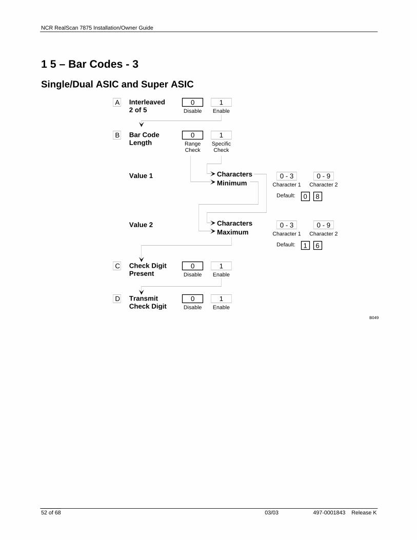
1 5 – Bar Codes - 3
Single/Dual ASIC and Super ASIC
Interleaved2 of 5
Bar CodeLength
Check DigitPresent
TransmitCheck Digit
Value 1 CharactersMinimum
Default:
Value 2 CharactersMaximum
Disable
0A
B
C
D
Enable
1
RangeCheck
0SpecificCheck
1
Character 1
0 - 3Character 2
0 - 9
0 8
Default:
Character 1
0 - 3Character 2
0 - 9
1 6
Disable
0Enable
1
Disable
0Enable
1
B049

NCR RealScan 7875 Installation/Owner Guide
497-0001843 Release K 03/03 53 of 68
1 7 – Bar Codes - 4
Single/Dual ASIC and Super ASIC
Minimum DataCharactersAllowed
Code 128
UCC 128
0Disable
A
B
C
1Enable
1 2 3 4 5
0
Disable
1
EnableB050
1 8 – Bar Codes - 5
Single/Dual ASIC and Super ASIC
20596
RSS Enable
Scans RequiredOn RSS 14
B
A
Disable
0Enable
RSS 14 Only
1
1 Scan
12 Scans
23 Scans
34 Scans
4
Enable RSS14E Only
2Enable
RSS 14 &RSS 14E
3
Scans RequiredOn RSS 14E
C
1 Scan
12 Scans
23 Scans
34 Scans
4
UCC-128EmulationMode
D
Normal Mode
0UCC-128
Emulation Mode
1

NCR RealScan 7875 Installation/Owner Guide
03/03 497-0001843 Release K54 of 68
1 6 – Label Identifiers
Single/Dual ASIC and Super ASIC
0
5
0
R0143
UPC-A
Identifier TypeDefault Prefix
Common Byte 1 Default:
Common Byte 2
Unique Identifier Default: Varies according to Bar Code Type.
Bar Code Type
Common Byte
A
B
C
D
2None
3Unique Prefix
0 - 7Hex Character
0 - FHex Character
Default:
D
4 20 - 7Hex Character
0 - FHex Character
2UPC-E
3EAN-8
4EAN-13
5Code 39
6Code 128
7Interleaved
2 of 5
0None
1Common Byte 1
2Common Byte 2
3Both Common
Bytes
0 - 7Hex Character
0 - FHex Character

NCR RealScan 7875 Installation/Owner Guide
497-0001843 Release K 03/03 55 of 68
2 0 – RS-232 Parameters - 1
Single/Dual ASIC and Super ASIC
0300
11809
Stop Bits AndCharacterLength
Note: Parity must be Odd or Even on a scale unit. Odd is used ifNone is selected.
Baud Rate
Handshake
Parity
A
B
C
D
1600
21200
32400
44800
59600
619200
0Odd
1Even
4None
01 Stop Bit
7-Bit Character
11 Stop Bit
8-Bit Character
22 Stop Bits
7-Bit Character
32 Stop Bits
8-Bit Character
0RTS Low
CTS Ignored
1RTS High
CTS Ignored
2Raise RTS
Wait for CTS
3Raise RTSIgnore CTS
4RTS Low
Wait for CTS
5RTS High
Wait for CTS

NCR RealScan 7875 Installation/Owner Guide
03/03 497-0001843 Release K56 of 68
2 1 – RS-232 Parameters - 2
Single/Dual ASIC
BCC Options
Disable
0 Default: Scanner Only - DisableScanner/Scale - Enable
InterfaceControl
B
Check DigitC
Note: Check Digit parameter also applies to UPC-Ewhen using for OCIA communictions.
11810
A
Enable
1
None
0ACK/NAK
1XOn/XOff
2ACK/NAK & XOn/XOff
3
0Disable UPC-ADisable EAN-8Disable EAN-13Disable UPC-E
1 2 3Enable UPC-AEnable EAN-8Enable EAN-13Disable UPC-E
Disable UPC-ADisable EAN-8Disable EAN-13Enable UPC-E
Enable UPC-AEnable EAN-8Enable EAN-13Enable UPC-E
Super ASIC
BCC Options Default: Scanner Only - DisableScanner/Scale - Enable
InterfaceControl
B
Check DigitC
20554
A
Disable
0Enable
1
None
0ACK/NAK
1XOn/XOff
2ACK/NAK & XOn/XOff
3
0Disable UPC-ADisable EAN-8Disable EAN-13Disable UPC-E
1Enable UPC-AEnable EAN-8Enable EAN-13Disable UPC-E
2Disable UPC-ADisable EAN-8Disable EAN-13Enable UPC-E
3Enable UPC-AEnable EAN-8Enable EAN-13Enable UPC-E

NCR RealScan 7875 Installation/Owner Guide
497-0001843 Release K 03/03 57 of 68
2 2 – RS-232 Prefix Byte
Single/Dual ASIC and Super ASIC
Prefix ByteA
ASCII Code
Disable
0
0 - 7 0 Default
Hex Character(ASCII Code Chart)
Enable
1
B 0 - F
Hex Character(ASCII Code Chart)
2
R0035
2 3 – RS-232 Terminator Byte
Single/Dual ASIC and Super ASIC
NOTE: A Terminator Byte is required on ascale unit. If you select Disable, it is ignored and an ETX (03) is sent.
Terminator ByteA
ASCII Code
Disable
0
0 - 7 0 Default
Hex Character(ASCII Code Chart)
Enable
1
B 0 - F
Hex Character(ASCII Code Chart)
3
11811

NCR RealScan 7875 Installation/Owner Guide
03/03 497-0001843 Release K58 of 68
2 4 – RS-232 Communications Options
Single/Dual ASIC and Super ASIC
Message Delay 0
No Delay
Scanner orScanner/ScaleFormat
Normal orEavesdropMode
Good Weigh Tone
1
10 ms Delay
2
50 ms Delay
4
Scanner Only
5
Scanner/Scale
6
Normal Mode
7
EavesdropMode
8
Disable
9
Enable12163
3 0 – Scale Parameters
Single/Dual ASIC and Super ASIC
Scanner/Scale
Model Number
IBM Address
3
9.995 kg / 13.995 kg
Scanner Only
4
Address 6A
5
Address 6B
6
Address 6E
7
Toggle Between9.995 kg and
13.995 kg
B
11812

NCR RealScan 7875 Installation/Owner Guide
497-0001843 Release K 03/03 59 of 68
3 2 – Miscellaneous Parameters
Single/Dual ASIC
IBM Tone Control(Good Read Tone Control)
OCIA Price Display
IBM Rexmit Control
OCIA Blank Display in Price Mode
Enable/Disable Voice Messages
IBM Tag Data Format
5-Second Weight Display TimerDisable
1Enable
2
Disable
3Enable
4
Disable
5Enable
6
3 Times
7Forever
8
Disable
9Enable
A
Toggle
D Default: Enabled
Hex
EASCII
F
11823
Super ASIC
IBM Tone Control(Good Read Tone Control)
IBM Rexmit Control
Enable/Disable Voice Messages
IBM Tag Data Format
Disable
3Enable
4
3 Times
7Forever
8
Toggle
D Default: Enabled
Hex
EASCII
F
20557

NCR RealScan 7875 Installation/Owner Guide
03/03 497-0001843 Release K60 of 68
3 6 – Dual Cable Interface Options
Single/Dual ASIC
Scale Type 0
No AdapterExit Parameter
A 1
Avery
2
Weightronix
3
TECParallel
4
CasioParallel
5
Datachecker
6
Toledo
14396
Note: The Super ASIC does not support Dual Cable Interface.

NCR RealScan 7875 Installation/Owner Guide
497-0001843 Release K 03/03 61 of 68
ASCII Code Chart
70
71
72
73
74
75
76
77
78
79
7A
7B
7C
7D
7E
7F
p
q
r
s
t
u
v
w
x
y
z
{
|
}
DEL
60
61
62
63
64
65
66
67
68
69
6A
6B
6C
6D
6E
6F
a
b
c
d
e
f
g
h
i
j
k
l
m
n
o
50
51
52
53
54
55
56
57
58
59
5A
5B
5C
5D
5E
5F
P
Q
R
S
T
U
V
W
X
Y
Z
[
\
]
^
_
40
41
42
43
44
45
46
47
48
49
4A
4B
4C
4D
4E
4F
@
A
B
C
D
E
F
G
H
I
J
K
L
M
N
O
30
31
32
33
34
35
36
37
38
39
3A
3B
3C
3D
3E
3F
0
1
2
3
4
6
5
7
8
9
:
;
<
=
>
?
20
21
22
23
24
25
26
27
28
29
2A
2B
2C
2D
2E
2F
SP
!
"
#
$
%
&
'
(
)
*
+
,
-
.
/
10
11
12
13
14
15
16
17
18
19
1A
1B
1C
1D
1E
1F
DLE
DC1
DC2
DC3
DC4
NAK
SYN
ETB
CAN
EM
SUB
ESC
FS
GS
RS
US
00
01
02
03
04
05
06
07
08
09
0A
0B
0C
0D
0E
0F
NULL
SOH
STX
ETX
EOT
ENQ
ACK
BEL
BS
HT
LF
VT
FF
CR
S0
S1
ASCII Code Chart
~
R0040

NCR RealScan 7875 Installation/Owner Guide
03/03 497-0001843 Release K62 of 68
Regulatory Information
Federal Communications Commission (FCC)Radio Frequency Interference Statement
Note: This equipment has been tested and found to comply with the limits for a Class Adigital device, pursuant to Part 15 of the FCC Rules. These limits are designed toprovide reasonable protection against harmful interference when the equipment isoperated in a commercial environment. This equipment generates, uses, and can radiateradio frequency energy and, if not installed and used in accordance with the instructionmanual, may cause harmful interference to radio communications. Operation of thisequipment in a residential area is likely to cause harmful interference in which case theuser is required to correct the interference at his own expense.
Information to User: This equipment must be installed and used in strict accordancewith the manufacturer’s instructions. However, there is no guarantee that interferenceto radio communications will not occur in a particular commercial installation. If thisequipment does cause interference, which can be determined by turning the equipmentoff and on, the user is encouraged to consult an NCR service representativeimmediately.
Caution: NCR is not responsible for any radio or television interference caused byunauthorized modifications of this equipment or the substitution or attachment ofconnecting cables and equipment other than those specified by NCR. Suchunauthorized modifications, substitutions, or attachments may void the user’s authorityto operate the equipment. The correction of interferences caused by such unauthorizedmodifications, substitutions, or attachments are the responsibility of the user.
Voluntary Control Council for Interference (VCCI)Radio Frequency Interference Statement
16105
Canadian Department of CommunicationsRadio Frequency Interference Statement
This digital apparatus does not exceed the Class A limits for radio noise emissions fromdigital apparatus set out in the Radio Interference Regulations of the CanadianDepartment of Communication.
Le présent appareil numérique n’émet pas de bruits radioélectriques dépassant leslimites applicables aux appareils numériques de la Class A prescrites dans le Règlementsur le brouillage radioélectriques édicté par Ministère des Communications du Canada.

NCR RealScan 7875 Installation/Owner Guide
497-0001843 Release K 03/03 63 of 68
Scale RegulatoryCountry, state, and local regulatory agency notification of an installation of a weighinginstrument or Point of Service terminal’s device is required. Failure to comply withgovernment Weights and Measures regulations can result in criminal prosecution ofindividuals and can jeopardize the ability to conduct normal business. The NCR 7875Scanner/Scale has been certified in many countries. Contact the NCR office of Weights& Measures and Laser Safety for specific country approvals.
NCR Office of Weights & Measures and Laser SafetyDennis A. Krueger2651 Satellite BoulevardDuluth, GA 30096-5810
Phone: 770-623-7743Fax: 770-623-7827E-Mail: [email protected]

NCR RealScan 7875 Installation/Owner Guide
03/03 497-0001843 Release K64 of 68
Declaration of ConformityManufacturer’s Name NCR Corporation
Manufacturer’s Address NCR CorporationRetail Systems Division - Atlanta2651 Satellite BoulevardDuluth, GA 30096-5810
Type of Equipment Information Technology Equipment - Bar Code Scanner
Model Number NCR RealScan 7875
NCR Corporation, 1700 South Patterson Boulevard, Dayton, OH 45459, USA, declaresthat the equipment specified above conforms to the referenced EU Directives andHarmonized Standards.
EU Directive Harmonized Standard(s)89/336/EEC (EMC) EN 55022: 1987 (CISPR 22)
EN 50082-1, Part 1: 1992IEC 801-2: 1984, Severity Level 3IEC 801-3: 1984, Severity Level 2IEC 801-4: 1988, Severity Level 2
73/23/EEC (Low Voltage) EN 60950: 1992 A1, A2, A3, A4, and A11EN 60825-1: 1993+A1+A2
*90/384/EEC(Non-Automatic WeighingInstruments)
EN45501: 1994
* This Directive is not applicable to scanner only models.
Director of Quality AssuranceNCR CorporationRetail Systems Division — Atlanta2651 Satellite BoulevardDuluth, GA 30096-5810
European Contact: International IP Counsel206 Marylebone RoadLondon, NW1 6LY, England

NCR RealScan 7875 Installation/Owner Guide
497-0001843 Release K 03/03 65 of 68
Laser Safety
Laser Safety and Name Plate LabelsThe NCR RealScan 7875 Scanner is not intended for long term viewing of the directlaser light. However, the unit is safe if used as it is intended.
16103
Class IIa Laser Product. Avoid Long-term Viewing of direct Laser Light.
Appareil à Laser de classe IIa Eviter Toute ExpositionProlongèe de la vue à la lumiè re laser directe.
Class IIa Producto Laser. Tratè De no ver directamente èl RayoLaser por mucho tiempò. (IEC CLASS 1 LASER PRODUCT)
NCR CORPORATIONDuluth, GA 30096
Date Manufactured
Class 7875Model
SerialTracer
This device complies with Part 15 of the FCC Rules.Operation is subject to the following two conditions:
undesired operation.
(1) This device may not cause harmful interference,and (2) this device must accept any interferencereceived, including interference that may cause
This apparatus does not exceed the Class A limitsfor radio noise emissions set out in the RadioInterference Regulations of Canada.
Le presént appareil n'emet pas de bruits
brouillage radioélectnique du Canada.
radioélectriques dépassant les limites de laClassé A prescrites dans le Reglement sur le
VDC 5 3 A12 2
-12 0.3One or more of the U.S. Patents listed below apply: Patents Pending 5,229,588; 4,868,375; 4,575,623; 4,797,551; 4,851,667; 4,253,018; 4,272,675; 4,282,426; 4,679,154; 5,194,722; 5,276,316; 5,334,825; 5,262,625; 5,256,865; 5,144,114; 5,152,355; 5,065,842; 5,023,818; 4,656,344; 4,715,457; 4,716,281; 4,760,539; 5,459,308; 5,531,293; D368,398; 5,886,336; 6,059,189; 6,082,186; 6,158,660
Complies with 21 CFR 1040.10 and 1040.11except for deviations pursuant to laser notice No 50, July 26, 2001
LISTEDI.T.E.E152553
ACN 000 003 592
VCCI-A
Assembly in Mexico
Laser Module Label
This laser moduledoes not complywith 21CFR1040.USE ONLY AS ACOMPONENT.
14953

NCR RealScan 7875 Installation/Owner Guide
03/03 497-0001843 Release K66 of 68
IEC Class 1 Laser IdentificationThe NCR RealScan 7875 is a CLASS 1 LASER PRODUCT.
Laser PowerThe NCR RealScan 7875 Scanner meets the following laser power requirements.
• Class IIa CDRH (Center for Devices and Radiological Health)• Class 1 EN60-825 (Europäische Norm)• Class 1 IEC 825-1 1993 (International Electrotechnical Commission)
Following is the radiant energy of the laser light as applied to each of the specifiedrequirements.
Maximum Average Radiant Power (CDRH Calculation) 1.4 microwattsAccessible Emission Limit (CDRH Calculation) 3.9 microwattsMaximum Radiant Power (EN60825-1 / IEC 825-1 Calculation) 1.19 milliwattsAccessible Emission Limit (EN60825-1 / IEC 825-1 Calculation) 1.20 milliwatts
Caution: Use of controls or adjustments or performance of procedures other thanspecified herein may result in hazardous radiation exposure.

NCR RealScan 7875 Installation/Owner Guide
497-0001843 Release K 03/03 67 of 68

NCR RealScan 7875 Installation/Owner Guide
03/03 497-0001843 Release K68 of 68
Copyright © 1996 – 2003 by NCR Corporation