Embed Size (px)
Citation preview

Outlines: Research:
•Magnet Designs: single/double bore, cold/warm yoke•Design Parameters: short sample limit, field quality,mechanics, quench protection, etc.
Development:•Short model Design and Technology•Cable, insulation, structural materials•Short Model Fabrication Status
R&D of Cos-theta Nb3Sn High-Field Dipolesfor VLHC
A.V. Zlobin, Fermilab
Second Annual VLHC MeetingOctober 16-18, 2000
Danfords, Port Jefferson, Long Island, NY

VLHC Annual Meeting16-18 October 2000
A. ZlobinR&D of Cos-theta Nb3Sn High-Field Dipoles for VLHC
2
First Nb3Sn Dipole Models
Several Nb3Sn short d ipole models were fabricated and testedto demonstrate the possibility to reach the field >10 T at 4.3 K.
Laboratory CERN UT LBNLAperture (mm) 50 50 50Number of layers 2 2 4Coil thickness (mm) 34 40 54Design Bmax @4.3 K (T) 10.0 11.5 13.0Test 1989 1995 1997
CERN/ELIN MSUT D20

VLHC Annual Meeting16-18 October 2000
A. ZlobinR&D of Cos-theta Nb3Sn High-Field Dipoles for VLHC
3
Design Parameters and Criteria
Target design parameters and requirements:– nominal field : Bnom=10-12 T– field range: Bnom/ Binj=50TeV/ 3TeV=17 Binj=0.6-0.7 T– good field quality in the operation cycle: 1986 SSC specs– sufficient physical & dynamic aperture: magnet bore >40 mm
Additional considerations:– mechanical stability: coil support structure– quench protection: minimal stored energy, low inductance– low cost: small coil & magnet x-sections, simple & inexpensive
technology– applicability of design and technological solution for full-scale magnets

VLHC Annual Meeting16-18 October 2000
A. ZlobinR&D of Cos-theta Nb3Sn High-Field Dipoles for VLHC
4
Magnetic Design Study
Cable 1.80x14.23mm 2 1.46x15.4mm2
Strand d iam. (mm) 1.0 1.0 1.0 0.81Bore d iam. (mm) 50 45 40 40Bss (T) 12.4 12.4 12.5 12.5Energy@11T (kJ/ m) 289 256 221 230Inductance (mH/ m)2.75 2.32 1.67 2.53Coil area (cm2) 33.0 30.1 26.6 28.7Pole width (mm) 17.5 16.2 15.0 14.6
bore diameter range 40-50 mm is OK large cable is better
Cross-sections of coils withbore diameter of 40-50 mm
Basic parameters: 2 layers cos-theta coilcoil thickness ~30 mm

VLHC Annual Meeting16-18 October 2000
A. ZlobinR&D of Cos-theta Nb3Sn High-Field Dipoles for VLHC
5
Cos-theta Coil Cross-Section
0 10
Rel. field errors
0 2 4 6 8 10 12 14 16 18 20
(x10E-5)
Strand : Nb3Sn 1.00 mm Cu:nonCu=0.85:1 Jc(12T, 4.2K)=2.0 kA/ mm 2
Cable: 28 strands 14.24×1.80 mm2, Keystone angle 0.9 degree Packing factor 0.88
Insulation: Thick 2*0.125 mm (20-50% overlap)
Coil: Two layers cos-theta Bore d iameter 43.5 mm 24 turns (11+13)Technique: Wind& react
VLHC Annual Meeting16-18 October 2000
A. ZlobinR&D of Cos-theta Nb3Sn High-Field Dipoles for VLHC
6
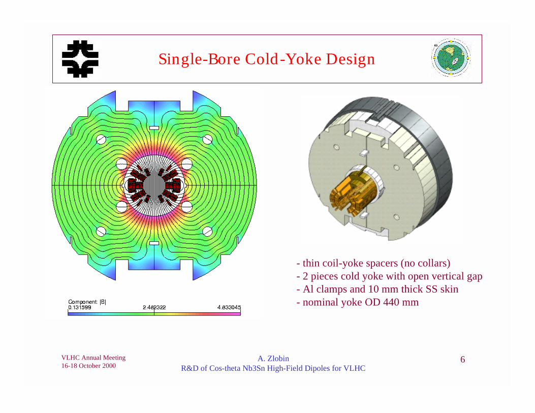
Single-Bore Cold-Yoke Design
- thin coil-yoke spacers (no collars)- 2 pieces cold yoke with open vertical gap- Al clamps and 10 mm thick SS skin- nominal yoke OD 440 mm

VLHC Annual Meeting16-18 October 2000
A. ZlobinR&D of Cos-theta Nb3Sn High-Field Dipoles for VLHC
7
Double-Bore Cold-Yoke Design
- bore d iameter 43.5 mm (same coil block)- bore separation 180 mm- 3 piece cold yoke with vertical gap- yoke OD 520 mm cryostat OD ~0.8-0.9 m- 10 mm thick SS skin- correction holes, gap along flux lines

VLHC Annual Meeting16-18 October 2000
A. ZlobinR&D of Cos-theta Nb3Sn High-Field Dipoles for VLHC
8
Double-Bore Warm-Yoke Design
- bore d iameter 43.5 mm- bore separation 180 mm- cold mass size 385 mm- thin SS skin- yoke OD 580 mm = cryostat OD- yoke thickness 40 mm- asymmetric coils

VLHC Annual Meeting16-18 October 2000
A. ZlobinR&D of Cos-theta Nb3Sn High-Field Dipoles for VLHC
9
Short Sample Limit & Nominal Field
Critical current margin - 15%Critical current degradation - 10%Cu:nonCu ration - 1.2:1
Maximum field vs. Jc@12T in the coilCu:nonCu=0.85:1
8
9
10
11
12
13
14
1000 1200 1400 1600 1800 2000 2200 2400 2600 2800 3000
Jc(12T), A/mm^2
B0, T
Single and double cold
Double w arm
Cold yoke Warm yokeJc(12T,4.2K), kA/mm2 Bnom, T Bmax, T Bnom, T Bmax, T 2.2 10 11.5 9.4 10.8 3.0 11 12.7 10.4 11.9
Bnom=11-12(cold yoke)/10-11 T(warm yoke)

VLHC Annual Meeting16-18 October 2000
A. ZlobinR&D of Cos-theta Nb3Sn High-Field Dipoles for VLHC
10
Field Quality
0.001
0.01
0.1
1
10
1 2 3 4 5 6 7 8 9 10 11
Harmonic numberan
, bn
(10^
-4)
SSC specs, bn
SSC specs, an
FNAL VLHC, bn&an
Random geometrical field errors @1 cm
∞
=
−
−
++×=+1
1
14 )(10),(),(
n
n
refnnxy R
iyxiabByxiByxB
Systematic geometrical field errors @1 cm
Bx(x,y) and By(x,y) – horizontal and vertical field components; B1 – dipole (main) component; Ref - reference radius (Rref =1 cm); bn and an – normal and skew harmonic coefficients.
Fieldharmonics
Coldyoke*
Warmyoke**
SSCspecs
b2 - 0.000 -b3 0.000 0.000 0.008b4 - 0.000 -b5 0.000 0.001 0.018b6 - -0.012 -b7 0.000 -0.011 0.040b8 - 0.031 -b9 -0.091 -0.13 0.089
b10 - -0.011 -*) Symmetric coil**) Asymmetric coil

VLHC Annual Meeting16-18 October 2000
A. ZlobinR&D of Cos-theta Nb3Sn High-Field Dipoles for VLHC
11
Iron Saturation Effect
Quadrupole vs. bore field
-1
-0.8
-0.6
-0.4
-0.2
0
0.2
0.4
0 2 4 6 8 10 12 14B0, T
b2, 1
0^-4
Double warmDouble cold
Sextupole vs. bore field
-4
-3
-2
-1
0
1
0 2 4 6 8 10 12 14B0, T
b3, 1
0^-4
Double warmDouble coldSingle cold
Summary:- cold yoke design - holes, Rout- warm yoke design - asymmetric coil, Rin
Transfer function vs. bore field
0.20
0.30
0.40
0.50
0.60
0.70
0 2 4 6 8 10 12 14B0, T
B0/I,
T/k
A
Cos(T) cold yoke
Cos(T) warm yoke

VLHC Annual Meeting16-18 October 2000
A. ZlobinR&D of Cos-theta Nb3Sn High-Field Dipoles for VLHC
12
Coil Magnetization Effect
-25
-20
-15
-10
-5
0
5
10
0 2 4 6 8 10 12
Bo, T
b3, 1
0^-4
w/o correction
0.15mm 'strips on the pipe'
Summary:Persistent currents: - small deff<40µm, passive correctionEddy current effects: - strand: small lp~10-20 mm
- cable: large Ra (cable with SS or iron core)

VLHC Annual Meeting16-18 October 2000
A. ZlobinR&D of Cos-theta Nb3Sn High-Field Dipoles for VLHC
13
Mechanical Analysis
Peak equivalent stress in the coil (MPa)
Design 300K 4.2 K, 0T 4.2K, 12 T
Single cold yoke 80 121 104Double cold yoke 120 132 125Double warm yoke 132 118 121
Summary:•coil stress: σeq<150 MPa and σaz>0 at all conditions•coil bore deformation is small: ∆R<100 µm•all structural elements work in elastic regime
4.2 K
11 T
300 K
1
2
3
4

VLHC Annual Meeting16-18 October 2000
A. ZlobinR&D of Cos-theta Nb3Sn High-Field Dipoles for VLHC
14
Quench Protection
Short model quench parameters:Quench integral, MIIT 12Tmax inner coil, K 180Tmax outer coil, K 130Vmax turn-turn, V 15Vmax coil-ground, V 100
Summary:•For long (10-15 m) magnets Cu:nonCu=1.2:1•Minimum heater energy: to be studied experimentally
Jcu~1.8-2.0 kA/mm2

VLHC Annual Meeting16-18 October 2000
A. ZlobinR&D of Cos-theta Nb3Sn High-Field Dipoles for VLHC
15
Research: Summary
The magnetic and mechanical design of single and double aperture d ipolemagnets for VLHC based on the cos-theta coil geometry with cold and warmiron yoke has been developed. All magnets met the target requirements:
• Bmax~10-11 T for commercially available Nb3Sn strands• Bnom~11-12 T with 15% margin will be achieved using new R&D strands• accelerator field quality is provided in the field range of 1-12 T. Field range can be
expended by reducing deff in R&D Nb3Sn strands and using simple passive correction• chosen mechanical designs and the coil prestress level provides the coil mechanical
stability in the fields up to 11-12 T but safe for Nb3Sn strand.• quench protection provided by the internal quench heaters. All quench parameters are
on the acceptable level. Some increase of the Cu content in full-scale coils is required.The cos-theta magnets provide higher maximum field in the same magnet bore,
have lower stored energy and smaller coil volume than common coil magnetsThe cos-theta design with warm yoke provides also significant reduction of
magnet size without a noticeable degradation of its characteristics

VLHC Annual Meeting16-18 October 2000
A. ZlobinR&D of Cos-theta Nb3Sn High-Field Dipoles for VLHC
16
Short Model Features
Design Features:•Nb3Sn cable•High temperature ceramic insulation•Bronze End Parts and Pole Pieces•Aluminum Spacers•400 mm Vertically Split Iron Yoke•Aluminum Clamps•8 mm thick Stainless Steel Skin•Stainless Steel Skin Alignment Key•50 mm thick SS end plates
We use some tooling and magnet parts from the HGQ project
Technology:•Wind and react technique•No Interlayer Splice•Simultaneous Reaction and Impregnation of two Half-Coils•Coil prestress provided by both Al clamps and SS Skin
VLHC Annual Meeting16-18 October 2000
A. ZlobinR&D of Cos-theta Nb3Sn High-Field Dipoles for VLHC
17
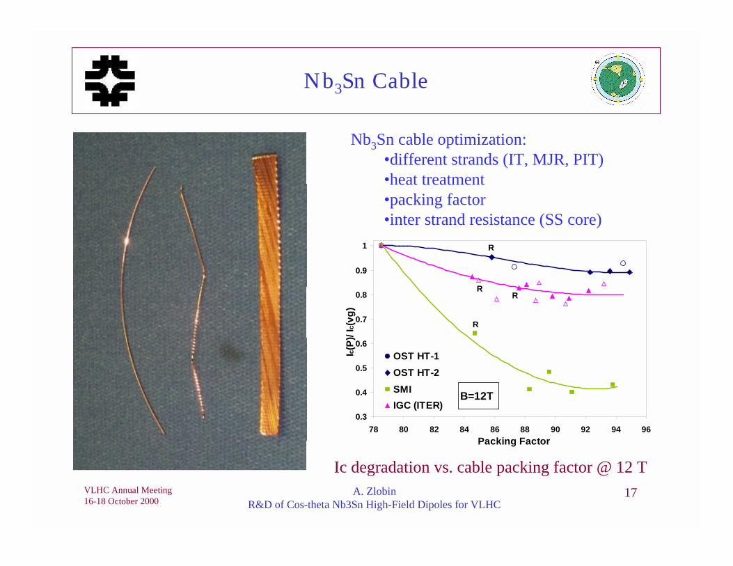
Nb3Sn Cable
Nb3Sn cable optimization:•different strands (IT, MJR, PIT)•heat treatment•packing factor•inter strand resistance (SS core)
Ic degradation vs. cable packing factor @ 12 T
0.3
0.4
0.5
0.6
0.7
0.8
0.9
1
78 80 82 84 86 88 90 92 94 96Packing Factor
Ic(P)
/ Ic(v
g)OST HT-1OST HT-2SMIIGC (ITER)
R
R
RR
B=12T

VLHC Annual Meeting16-18 October 2000
A. ZlobinR&D of Cos-theta Nb3Sn High-Field Dipoles for VLHC
18
Insulation
S-2 Fiber Glass Tape:• affordable, traditionally being used to insulate Nb3Sn cable• involves lot of pre-processing• was very weak to be used with an automated wrapping
machine• was improved in collaboration with a weaving company
by orienting the fibers in the favorable d irection• were recently successfu l in using S-2 glass tape w/ o any
organic binder
Ceramic Fiber Tape:• does not contain any organic binder• is strong enough to use for wrapping around the cable• expensive
Ceramic Binder (CTD Inc.):• is an inorganic adhesive• used to improve cable insulation stiffness before coil
winding and to form the coils into right shape during coilcuring.
Cable insulation using theInsulation Wrapping Machine

VLHC Annual Meeting16-18 October 2000
A. ZlobinR&D of Cos-theta Nb3Sn High-Field Dipoles for VLHC
19
25º
10º
BEND suggested angle = 43.2°
End Part Optimization
C o s t f o r 4s e t s
( 8 4 p a r t s )
C o s tp e r p a r t
M a c h i n i n gT i m e
( m i n u t e s )
5 - a x i s m i l l i n g 3 2 , 0 0 0 3 8 0 6 0 - 1 2 05 - a x i s w a t e r j e t
m a c h i n i n g1 4 , 0 0 0 1 6 0 1 0 - 1 5
Summary:•Rapid prototyping techniques reduce the time and cost of end part optimization process.•Emerging technologies such as water jet machining promise of significant reduction ofthe end part fabrication cost.

VLHC Annual Meeting16-18 October 2000
A. ZlobinR&D of Cos-theta Nb3Sn High-Field Dipoles for VLHC
20
Coils Winding and Curing
445.4 mm 343.8 mm210.8 mm
Two half coils ready to be reacted
Inner layer winding

VLHC Annual Meeting16-18 October 2000
A. ZlobinR&D of Cos-theta Nb3Sn High-Field Dipoles for VLHC
21
Coil Reaction
Coils Assembled in the Reaction Fixture
Reaction cycle:575 oC for 200 h followed by 700 oC for 40 hwith a ramp rate of 25 oC/h
Good bonding between the turns after reaction(allows to handle the coil easily and even performsize measurements under pressure)
Coil after reaction

VLHC Annual Meeting16-18 October 2000
A. ZlobinR&D of Cos-theta Nb3Sn High-Field Dipoles for VLHC
22
Epoxy Impregnation
Impregnation set up
Impregnated Coil
Impregnation:•epoxy CTD 101K•time 5 h
Curing: •temperature 125oC •duration 20 h

VLHC Annual Meeting16-18 October 2000
A. ZlobinR&D of Cos-theta Nb3Sn High-Field Dipoles for VLHC
23
Mechanical Measurements
-0.6
-0.4
-0.2
0
0.2
0.4
0.6
0.8
1
1.2
0 5 10 15 20 25 30 35Pressure, MPa
Dev
iatio
n fr
om N
omin
al S
ize,
mm
After Reaction
Before Reaction
Azimuthal Size Variation
Summary: Azimuthal size of the coils should be less than nominal•Reduces the compaction of coils in the reaction fixture•Coil will grow to the nominal size after reaction
InductanceµµµµH
QualityFactor
ResistancemΩΩΩΩ
BEFORE REACTIONFirst Half Coil 232.4 6.01 56.5
Second Half Coil 236.4 6.36 62.8AFTER REACTION
First Half Coil 94.3 0.93 78.6Second Half Coil 200.8 2.68 81.9
Coil Azimuthal Size: increased after reaction by 0.7 mmCoil Length Variation: increased by 9mm after reactionObservation: - turn-to-turn shorts in the first half coil
- tin leakage in the coils.Possible Cause: - strand/cable mechanical defects, - removal of low temperature (200 oC) step
from the reaction cycle - high compaction of coils in the fixture before reaction.
Electrical Measurements

VLHC Annual Meeting16-18 October 2000
A. ZlobinR&D of Cos-theta Nb3Sn High-Field Dipoles for VLHC
24
Coil and Yoke Assembly
Short model assembled with iron yoke

VLHC Annual Meeting16-18 October 2000
A. ZlobinR&D of Cos-theta Nb3Sn High-Field Dipoles for VLHC
25
Mechanical Model
Coil block Yoked MechanicalModel
CoilPole
SpacerMid-Plane Pole
ModelUnder Press 154 88 152Under Press + Clamp 156 91 161After Spring back 32 40 51
AnalysisUnder Press 145 122 156After Spring back 40 43 50
Mechanical calculations and measurements correlate quite well.
Azimuthal Stress Measurements (MPa)

VLHC Annual Meeting16-18 October 2000
A. ZlobinR&D of Cos-theta Nb3Sn High-Field Dipoles for VLHC
26
Development: Short Model Program Status
The developed coil design and fabrication technique resulted in a coilwith good mechanical properties.
Coil size and reaction process needs to be optimized to eliminate over-sizing, tin leaks and turn-to-turn shorts.
The magnet assembly procedure and the ANSYS analysis have beenverified using short model assembly and mechanical models
Fabrication of new coils for the first short model is in progress and weexpect to complete the production in January 2001 and test it inFebruary 2001.
Fabrication of cable for second and third short models is scheduled forNovember. Magnet fabrication will starts in December 2000.
Second model tests are expected in May 2001.
VLHC Annual Meeting16-18 October 2000
A. ZlobinR&D of Cos-theta Nb3Sn High-Field Dipoles for VLHC
27
Acknowledgments
N. Andreev, G. Ambrosio, E. Barzi, P. Bauer, D. Chichili, V. Kashikhin,P.J. Limon, I. Terechkine, J.C. Tompkins, S. Yadav, R. Yamada,V. Yarba, FNAL, Batavia, IL, USAS. Caspi, R. Scanlan LBNL, Berkeley, CA, USAM. Wake, KEK, Tsukuba, Japan


![p.dmm.com · 2016-08-05 · Instagram RICOH THETA theta3600fficial RICOH RICOH THETA official RICOH THETA 13 I Tube RICOH THETA . RICOH imagine. change. rRlCOH THETA ETA] RIC THETA](https://img.dokumen.tips/doc/110x75/5fa315d5ae82834598690dcf/pdmmcom-2016-08-05-instagram-ricoh-theta-theta3600fficial-ricoh-ricoh-theta.jpg)