Embed Size (px)
Citation preview

Ray Tracing and Full-wave Simulation of KSTAR LH Wave
2016 KO-JA Workshop on Physics and Technology of Heating and Current Drive
Presented by Young-soon Bae
NFRIaW. Namkung, aM.H. Cho, bS. Shiraiwa, cS.C. Kim, cY.S.
HwangaPOSTECH, bMIT, cSNU
Outline
LH wave accessibility and Landau damping
Off-midplane and inside launching
Ray tracing study of outside midplane launcher
Full-wave simulation for wave coupling and propagation
Summary
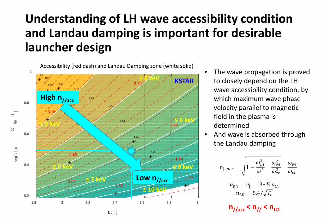
Understanding of LH wave accessibility condition and Landau damping is important for desirable launcher design
1.691.79
1.92
2.112.22
2.32
2.43
2.54
2.64
2.75
2.85
2.96
3.07
3.17
3.28
3.393.49
3.63.7
1.73
1.83
1.94
2.07
2.24
2.45
2.74
3.16
1.8 2 2.2 2.4 2.6 2.8 3
Bt [T]
0.2
0.4
0.6
0.8
1
ne(0
) [10
20/m
3]
≤ 3 keV
≤ 4 keV
≤ 5 keV
≤ 6 keV
≤ 7 keV
≤ 8 keV
≤ 10 keV𝑣𝑣𝑝𝑝𝑝 = 𝑣𝑣|| = 3~5 𝑣𝑣𝑡𝑡𝑝𝑛𝑛𝐿𝐿𝐿𝐿 = 5.4/ 𝑇𝑇𝑒𝑒
Accessibility (red dash) and Landau Damping zone (white solid)
𝑛𝑛||,𝑎𝑎𝑎𝑎𝑎𝑎 = 1 −𝜔𝜔𝑝𝑝𝑝𝑝2
𝜔𝜔2 +𝜔𝜔𝑝𝑝𝑒𝑒2
𝜔𝜔𝑎𝑎𝑒𝑒2+𝜔𝜔𝑝𝑝𝑒𝑒𝜔𝜔𝑎𝑎𝑒𝑒
KSTAR• The wave propagation is proved
to closely depend on the LH wave accessibility condition, by which maximum wave phase velocity parallel to magnetic field in the plasma is determined
• And wave is absorbed through the Landau damping
n//acc < n// < nLD
Low n//acc
High n//acc

Wave accessibility and Landau damping for H-mode density profile
Outside(Outboard)Inside
“Inside launch”: higher field increases the window for accessibility and strong LD allowing lower n// to penetrate, which improves efficiency since η ~ 1/n//
2

The off-midplane launch has a benefit of significant upshift on the evolution n//
• Off-midplane launchRobust accessibility and off-axis current drive avoiding wave interactions in SOL region (PDI, power spectrum splitting, collisional damping, etc)
Y.S. Bae et al, PPCF 58 (2016) 075003

Outside midplane launcher in KSTAR 5 GHz LHCD
• Conventional grill waveguide launcher
• To be replaced by steady state launcher (PAM)

Ray tracing and Fokker Planck calculation for KSTAR outside midplane LH launcher using GENRAY/CQL3D code
For simplicity, only main forward peak is considered in GENRAY/CQL3D simulations- total launched power of 1.5 MW loaded to forward power
Plasma density and temperature profile- Theoretical H-mode pedestal profile near rho = 0.9
Midplane launcher:4-row 5.8 cm height waveguide grills launcher 2-cm behind LCFS
LCFS

Multiple reflections in 2 T case even with high n// = 2.5
2T 2.5T
ne=3e19/m3, Te=5keV

LH-drive current profile is strongly dependent upon temperature and density profiles both for n// = 2.0 and 2.5
B0= 2.5 T, n//=2.0
Temperature Density
B0= 2.5 T, n//=2.5

Current drive efficiency for Bt = 2.0 T
Current drive dependency on the density for various Te(0) and n//(2.0, 2.2, 2.5)
• for ne(0)=7x10¹⁹/m3, 80~150kA/MW and η = 1~2.8x10¹⁹ Am-2W-1 for Te(0)=3-10keV
η = ne*R*Icd/Pabs
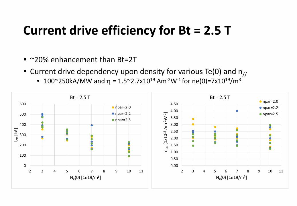
Current drive efficiency for Bt = 2.5 T
~20% enhancement than Bt=2T Current drive dependency upon density for various Te(0) and n//
• 100~250kA/MW and η = 1.5~2.7x10¹⁹ Am-2W-1 for ne(0)=7x10¹⁹/m3

Current drive efficiency for Bt = 3.0 T Similar CD efficiency as Bt=2.5T Current drive dependency upon density for various Te(0) and n//
• 120~200kW/MW and η = 1.5~3.0x10¹⁹ Am-2W-1 for ne(0)=7x10¹⁹/m3

Effect of fast electron diffusion
Confinement time of fast electronτF/τE ~ γαα = 3~4In Cylindrical geometry,χF ≈ a2/(6τF)
If 100 keV, γ = 1.1956; For KSTAR,τF = τE γα ≈ 0.1 s x 1.19563 ~ 0.2 sχF ~ 0.2 m2/s
ne(0)=5x10¹⁹/m3
Te(0)=7 keV
ICD decreases by ~20%

Reversed spectrum from the launcher with forward to reverse power loading, 70:30% results in reduced current drive by ~ 40%
With reversed spectrumICD = 180 kA
7:3
With only main peakICD = 320 kA
n// = ∆𝝋𝝋𝒌𝒌𝟎𝟎𝒑𝒑
+ 𝟐𝟐𝝅𝝅𝒎𝒎𝑵𝑵𝒌𝒌𝟎𝟎𝒑𝒑
,𝒎𝒎 = 𝒍𝒍𝑵𝑵, 𝒍𝒍 = 𝟎𝟎, ±𝟏𝟏, ±𝟐𝟐, …
p is periodN is number of active waveguide in each PAM module
∆ϕ=270deg l=0, n//=-2.5 (main lobe)l=-2, n//=4.2 (opposite lobe)
Only main peak
With reversed spectrum

Multiple side lobes results in much smoother spectral gap “filling”
Multiple high ntor side lobes are predicted by theoretical calculation of power spectrum from the grill launcher
- 3 high ntor peaks are included for n0 = 2.5- Different from customary approach with the only main
peak, which tends to result in poorer spectral phase space “filling”

Proposed configuration of KSTAR 3 MW PAM launcher using 8 x 0.5 MW klystrons
PA
4 active x 4 passive
4-way splitter
3-dB hybrid splitterK1 2 way x 4 way x 4 active x 8 klys = 256
active wgs (32 toroidal x 8 poloidal)n// = ∆𝝋𝝋
𝒌𝒌𝟎𝟎𝒑𝒑+ 𝜹𝜹𝝋𝝋−𝟏𝟏𝟏𝟏𝟎𝟎°
𝑵𝑵𝒘𝒘𝒘𝒘𝒌𝒌𝟎𝟎𝒑𝒑×𝟏𝟏𝟏𝟏𝟎𝟎/𝝅𝝅=2.5
A P
7mm 5 mm 3 mm
180deg
∆ϕ=270deg
Power flux3MW/256/(58mmx7mm)= 28.8MW/m2
ITER design: 33 MW/m2
Tore Supra: 25 MW/m2 (2.7 MW during 78 s) to be increased to > 30 MW/m2
55 mm
X 8
Kn-1 Knδϕ=180deg
Nwg = 4p = 18mm250kW CW
BeO window
~600
mm

RF power reflection calculation in PAM launcher from the edge plasma using FEM-based full-wave simulation
COMSOL Multiphysics® model16 active and 17 passive waveguidesWith bA = 7 mm, bP = 7 mm (5 mm), e = 3mm (2mm)
Plasma model: Dielectric tensor in Stix’s frame
𝑘𝑘 × 𝑘𝑘 × 𝐸𝐸 − 𝑘𝑘02 𝜖𝜖𝑟𝑟 − 𝑖𝑖𝜎𝜎𝜔𝜔𝜖𝜖0
𝐸𝐸 = 0
Wave equation
𝜖𝜖𝑟𝑟 =𝑆𝑆 −𝑖𝑖𝑖𝑖 0𝑖𝑖𝑖𝑖 𝑆𝑆 00 0 𝑃𝑃
Plasma
Plasma with high conductivity
Perfect Matched Layer (PML)
Bt

Wave propagation from the PAM grill waveguides shows two main lobes of the radiation spectrum
Nwg = 16nmain = -2.5; nopp = 4.1
bA=7mm,bP=5mm,e=3mmne(0)=0.6x10¹⁸/m3
bA=7mm,bP=7mm,e=2mmne(0)=0.6x10¹⁸/m3
Directivity = 55 %
Fourier Transform of Ex near the launcher

Power reflection as a function of edge density (ne_edge) and density gradient (ne/∇ne)
bA=7mm, bP=5mm, e=3 mm
• Reflection changes significantly with density gradient at the low density regime, but less effect at high density regime
bA=7mm, bP= 7 mm, e = 2 mm

LH wave propagation inside tokamak using FEM-based full-wave simulation Collaboration with MIT
Conventional PDE solved by COMSOLConvolution integral done in LiveLink® Matlab

Stix’s dielectric tensor should be rotated with two angles defined by 3D equilibrium magnetic field data (Bx, By, Bz)
• Dielectric tensor in Stix’s frame KSTAR
𝜀𝜀 =𝑆𝑆 −𝑖𝑖𝑖𝑖 0𝑖𝑖𝑖𝑖 𝑆𝑆 00 0 𝑃𝑃 − 𝑖𝑖𝜀𝜀𝐸𝐸𝐿𝐿𝐿𝐿
R(θ, φ) • ε • R(-θ, -φ)θ and φ is defined with Bx, By, Bz
• Rotation of dielectric tensor

Summary
Using GENRAY/CQL3D code, the wave ray tracing and its current drive are studied for KSTAR outside midplane launcher.
The simulation results show that high toroidal magnetic field or high launched n// is recommended according to accessibility condition and strong Landau damping.
A significant LH wave current drive could be obtained for the wave spectrum with peak value n// = 2.5 if a toroidal magnetic field Bt = 2.5 ~ 3.0 T is applied.
Further studies in full wave simulation is planned for the investigation of the of LH wave non-linear interaction in SOL region and edge region.
Proposed off-midplane (top launcher) for strong single pass absorption hence high CD efficiency in KSTAR LHCD is being considered for future upgrade

Next time, I hope to see you again in Hokkaido (?) with another topic of top launcher of ECH

Lower hybrid wave penetration and absorption
Lower hybrid wave frequency in tokamak
24
𝜔𝜔𝐿𝐿𝐿𝐿 =𝜔𝜔𝑝𝑝𝑝𝑝
1 + �𝜔𝜔𝑝𝑝𝑒𝑒2𝜔𝜔𝑎𝑎𝑒𝑒2
1/2
𝜔𝜔 > 5𝜔𝜔𝐿𝐿𝐿𝐿
𝑛𝑛||1 = 1 +𝜔𝜔𝑝𝑝𝑒𝑒2
𝜔𝜔𝑎𝑎𝑒𝑒21 −
𝜔𝜔𝑎𝑎𝑒𝑒𝜔𝜔𝑎𝑎𝑝𝑝
𝜔𝜔2 +𝜔𝜔𝑝𝑝𝑒𝑒𝜔𝜔𝑎𝑎𝑒𝑒
𝑛𝑛||2 =30
𝑇𝑇𝑒𝑒(𝑘𝑘𝑘𝑘𝑘𝑘)↔ 𝑣𝑣𝑝𝑝𝑝 = 𝑣𝑣|| = 3𝑣𝑣𝑡𝑡𝑝
𝑛𝑛||2 =49
𝑇𝑇𝑒𝑒(𝑘𝑘𝑘𝑘𝑘𝑘)↔ 𝑣𝑣𝑝𝑝𝑝 = 𝑣𝑣|| = 2.3𝑣𝑣𝑡𝑡𝑝
• Accessibility
• Landau damping
𝜔𝜔𝐺𝐺𝐺𝐺2 = 𝜔𝜔𝑎𝑎𝑒𝑒𝜔𝜔𝑎𝑎𝑝𝑝
Linear
QuasiLinear
Density limit (related to PDI)ne(0) = 1 x 10²⁰/m3, Bt = 2 T


![Optimized Deployment of Millimeter Wave …human body blockage and user orientation. In [6], the authors used 3D ray tracing to evaluate In [6], the authors used 3D ray tracing to](https://img.dokumen.tips/doc/110x75/5f0a573e7e708231d42b2c27/optimized-deployment-of-millimeter-wave-human-body-blockage-and-user-orientation.jpg)