Embed Size (px)
Citation preview

Ramp/Soak Process Controller E5CK--TA--180
Ramp/Soak Process Controller
E5CK--TAdvanced, 1/16-DIN Ramp/SoakProcess Controllers Ideal forWorldwide Use
D Offers one pattern of simple programming control, up tofour patterns with communications (16 steps perpattern).
D Water-resistant front face meets IP66/NEMA 4 (indooruse).
D Modular structure, one-stock type.
D Heat/Cool control.
D Serial communications (RS-232C and RS-485).
D Temperature and analog inputs.
D High-accuracy: 100 ms sampling (for analog input).
D Conforms to international EMC and safety standards.
D 3-year warranty.
RC
Ordering InformationOrder control output boards and option boards separately. A single output board and option board can be mounted to each base unit. Forexample, for a relay control output, order the E53-R4R4 output board in addition to the E5CK-TAA1-500 Process Controller. Model with
-500 has a terminal cover for finger protection
JProcess ControllersStock Note: Shaded models are normally stocked.
Description DIN size Supply voltage Model
Base unit with terminal cover 1/16 DIN(48 48 )
100-240 VAC E5CK-TAA1-500 AC100-240/(48 x 48 mm)
E5CK-TAA1 AC100-240
Note: Part numbers ending in -500 available at Omron USA, non -500 numbers available in Omron Canada only. Model with -500 has a
terminal cover for finger protection.
JOptional Output BoardsStock Note: Shaded models are normally stocked.
Description Specifications Max. quantity Model
Relay/Relay SPST/SPST, 5 A, 250 VAC 1 E53-R4R4
Relay/Pulse SPST, 5 A/NPN, 24 VDC 1 E53-Q4R4y/
SPST, 5 A/PNP, 24 VDC 1 E53-Q4HR4
Relay/Linear current SPST, 5 A/4--20 mA 1 E53-C4R4y/
SPST, 5 A/0-20 mA 1 E53-C4DR4
Relay/Linear voltage SPST, 5 A/0-10 VDC 1 E53-V44R4
Pulse/Pulse NPN/NPN, 24 VDC 1 E53-Q4Q4/
PNP/PNP, 24 VDC 1 E53-Q4HQ4H
Computer communications RS-232C 1 E53-CK01p
RS-485 1 E53-CK03
Event input For remote set point 1 E53-CKB
Transfer output 4 to 20 mA 1 E53-CKF
Note: If the control period is less than 5 seconds, use an SSR (solid state relay) or pulse voltage output.

Ramp/Soak Process Controller E5CK--T A--181
JAccessories (Order Separately)
Stock Note: Shaded models are normally stocked.
Description Specifications Compatible controller Max. quantity Model
Current transformer; orderonly if using heater
50 A load, 5.8 mm hole dia. E5CK-T 1 E54-CT1only if using heaterburnout alarm function 120 A load, 12 mm hole dia. E5CK-T 1 E54-CT3
Terminal cover (suppliedwith -500 models)
Provides finger protection fromterminals (VDE0106 part 100)
E5CK-T 1 E53-COV07
Software For setup and monitoring;requires optional computercommunications board
All 1 Thermo Tools(see Note)
Note: Contact Omron for current version information.
Specifications
JRatingsModel E5CK-T
Supply voltage 100 to 240 VAC, 50/60 Hz
Power consumption 15 VA
Operating voltage range 85% to 110% of rated supply voltage
Input Thermocouple K, J, T, E, L, U, N, R, S, B, W, PLIIp
Platinum resis-tance thermometer
JPt100, Pt100
Current input 4 to 20 mA, 0 to 20 mA
Voltage input 1 to 5 V, 0 to 5 V, 1 to 10 V
Input impedance Current input 150 Ωp p
Voltage input 1 MΩ min.
Control output According to Output Board (see Output Board Ratings and Characteristics)
Auxiliary output SPST-NO, 1 A at 250 VAC (resistive load)
Control method ON/OFF or advanced PID control
Setting method Digital setting using front panel keys or communications features
Indication method 7-segment digital display and LEDs
Additional functions Standard Manual output, heating/cooling control, SP limiter, loop burnout alarm, MV limiter,MV change rate limiter, input digital filter, input shift, run/reset, protect functions,scaling function

Ramp/Soak Process Controller E5CK--TA--182
JCharacteristicsIndication accuracy(S N t 1)
Thermocouple ±0.3% of indication value or ±1°C, whichever greater, ±1 digit max.y(See Note 1)
Platinumresistancethermometer
±0.2% of indication value or ±0.8°C, whichever greater, ±1 digit max.
Analog input ±0.2% of indication value, ±1 digit max.
Hysteresis 0.01% to 99.99% FS (in units of 0.01% FS)
Proportional band (P) 0.1% to 999.9% FS (in units of 0.1% FS)
Integral (reset) time (I) 0 to 3,999 s (in units of 1 s)
Derivative (rate) time (D) 0 to 3,999 s (in units of 1 s)
Control period 1 to 99 s (in units of 1 s)
Manual reset value 0.0% to 100.0% (in units of 0.1%)
Alarm setting range --1,999 to 9,999 or --199.9 or 999.9 (decimal point position dependent on input type)
Set time 0 to 99 hrs 59 min or 0 to 99 min 59 s
Program capacity 1 pattern, 16 steps (possible to use up to 4 patterns with the communications func-tion.)
Programming method Time or ramp setting method
Time accuracy ±0.2% (±500 ms) of the set value
Sampling period(S N t 2)
Temperature input 250 msp g p(See Note 2)
Analog input 100 ms
Insulation resistance 20 MΩ min. (at 500 VDC)
Dielectric strength 2,000 VAC, 50/60 Hz for 1 min between terminals of different polarities
Vibration resistance Malfunction 10 to 55 Hz, 10 m/s2 (approx. 1G) for 10 min each in X, Y, and Z directions
Destruction 10 to 55 Hz, 20 m/s2 (approx. 2G) for 2 hrs each in X, Y, and Z directions
Shock resistance Malfunction 200 m/s2 min. (approx. 20G), 3 times each in 6 directions (100 m/s2 (approx. 10G)applied to the relay)
Destruction 300 m/s2 min. (30G), 3 times each in 6 directions
Ambient temperature Operating --10°C to 55°C (with no icing)/3-year warranty period: --10°C to 50°Cp
Storage --25°C to 65°C (with no icing)
Ambient humidity Operating 35% to 85%
Enclosure ratings Front panel NEMA 4 for indoor use (equivalent to IP66)g
Rear case IEC standard IP20
Terminals IEC standard IP00
Memory protection Non-volatile memory (number of writings: 100,000 operations)
Weight Approx. 170 g;Adapter: approx. 10 g
EMC Emission Enclosure: EN55011 Group 1 class AEmission AC Mains: EN55011 Group 1 class AImmunity ESD: EN61000-4-2: 4kV contact discharge (level 2)
8kV air discharge (level 3)Immunity RF-interference: ENV50140: 10V/m (amplitude modulated,
80 MHz to 1 GHz) (level 3)10 V/m (pulse modulated, 900MHz)
Immunity Conducted Disturbance: ENV50141: 10V (0.15 to 80 MHz ) (level 3)Immunity Burst: EN61000-4-4: 2kV power-line (level 3)
2kV I/O signal-line (level 4)
Approved standards UL1092, CSA22.2 No. 14, CSA22.2 No. 1010-1Conforms to EN50081-2, EN50082-2, EN61010-1 (IEC1010-1)Conforms to VDE0106/part 100 (Finger Protection), when the separately-orderedterminal cover is mounted.
Note: 1. The indication accuracy of the K1, T, and N thermocouples at a temperature of -100°C max. is ±2°C ±1 digit maximum. Theindication accuracy of the U and L thermocouples at any temperature is ±2°C ±1 digit maximum.The indication accuracy of the B thermocouple at a temperature of 400°C max. is unrestricted.The indication accuracy of the R and S thermocouples at a temperature of 200°C max. is ±3°C ±1 digit maximum.The indication accuracy of the W thermocouple at any temperature is (±0.3% of the indicated value or ±3°C, whichever is great-er) ±1 digit maximum. The indication accuracy of the PLII thermocouple at any temperature is (±0.3% or ±2°C, whichever isgreater) ±1 digit maximum.
2. The sampling period of the standard model with CT and remote SP inputs is 250 ms.
Ramp/Soak Process Controller E5CK--T A--183
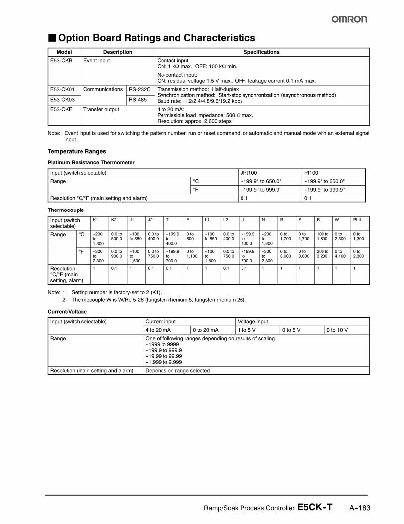
JOption Board Ratings and Characteristics
Model Description Specifications
E53-CKB Event input Contact input:ON: 1 kΩ max., OFF: 100 kΩ min.
No-contact input:ON: residual voltage 1.5 V max., OFF: leakage current 0.1 mA max.
E53-CK01 Communications RS-232C Transmission method: Half-duplexSynchronization method: Start-stop synchronization (asynchronous method)
E53-CK03 RS-485Synchronization method: Start-stop synchronization (asynchronous method)Baud rate: 1.2/2.4/4.8/9.6/19.2 kbps
E53-CKF Transfer output 4 to 20 mA:Permissible load impedance: 500 Ω max.Resolution: approx. 2,600 steps
Note: Event input is used for switching the pattern number, run or reset command, or automatic and manual mode with an external signal
input.
Temperature Ranges
Platinum Resistance Thermometer
Input (switch selectable) JPt100 Pt100
Range °C --199.9° to 650.0° --199.9° to 650.0°
°F --199.9° to 999.9° --199.9° to 999.9°
Resolution °C/°F (main setting and alarm) 0.1 0.1
Thermocouple
Input (switchselectable)
K1 K2 J1 J2 T E L1 L2 U N R S B W PLII
Range °C --200to1,300
0.0 to500.0
--100to 850
0.0 to400.0
--199.9to400.0
0 to600
--100to 850
0.0 to400.0
--199.9to400.0
--200to1,300
0 to1,700
0 to1,700
100 to1,800
0 to2,300
0 to1,300
°F --300to2,300
0.0 to900.0
--100to1,500
0.0 to750.0
--199.9to700.0
0 to1,100
--100to1,500
0.0 to750.0
--199.9to700.0
--300to2,300
0 to3,000
0 to3,000
300 to3,200
0 to4,100
0 to2,300
Resolution°C/°F (mainsetting, alarm)
1 0.1 1 0.1 0.1 1 1 0.1 0.1 1 1 1 1 1 1
Note: 1. Setting number is factory-set to 2 (K1).
2. Thermocouple W is W/Re 5-26 (tungsten rhenium 5, tungsten rhenium 26).
Current/Voltage
Input (switch selectable) Current input Voltage input
4 to 20 mA 0 to 20 mA 1 to 5 V 0 to 5 V 0 to 10 V
Range One of following ranges depending on results of scaling--1999 to 9999--199.9 to 999.9--19.99 to 99.99--1.999 to 9.999
Resolution (main setting and alarm) Depends on range selected

Ramp/Soak Process Controller E5CK--TA--184
Nomenclature
JE5CK-T
Operation Indicators
RUN/RST Key
Up Key/Down Key
Display Key
Display 1
Display 2
Dimensions
Unit: mm (inch)
JE5CK-T
60(2.36)min.
Panel Cutouts65
(2.56)min.
48(1.89)
58 (2.28)
13.3(0.52)
100 (3.94)53L x 53W
44.8X44.8
JAccessoriesTerminal CoverE53-COV07
44.3(1.74)
44.3(1.74)
1.5(0.06)
Note: Terminal cover is supplied for controller with -500 in the part number; for non-500 model, order separately.
Ramp/Soak Process Controller E5CK--T A--185
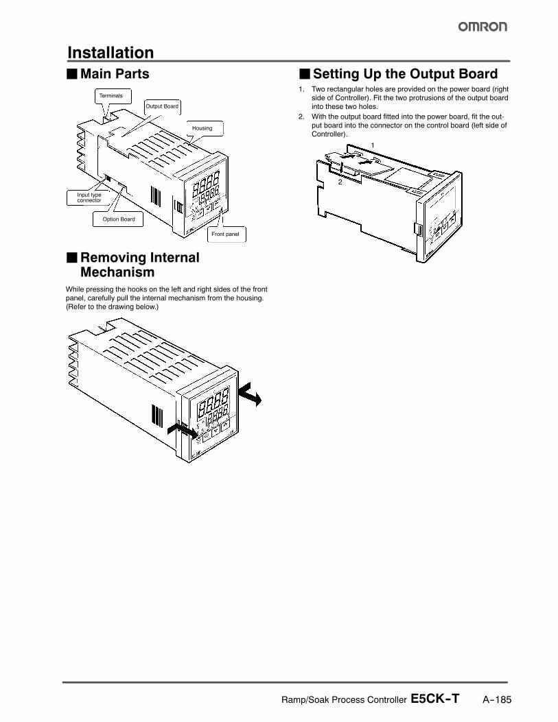
Installation
JMain Parts
Terminals
Output Board
Housing
Front panel
Option Board
Input typeconnector
JRemoving InternalMechanism
While pressing the hooks on the left and right sides of the front
panel, carefully pull the internal mechanism from the housing.(Refer to the drawing below.)
JSetting Up the Output Board1. Two rectangular holes are provided on the power board (right
side of Controller). Fit the two protrusions of the output boardinto these two holes.
2. With the output board fitted into the power board, fit the out-
put board into the connector on the control board (left side ofController).
1
2
Ramp/Soak Process Controller E5CK--TA--186
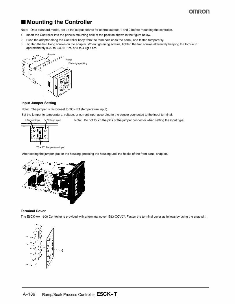
JMounting the Controller
Note: On a standard model, set up the output boards for control outputs 1 and 2 before mounting the controller.
1. Insert the Controller into the panel’s mounting hole at the position shown in the figure below.
2. Push the adapter along the Controller body from the terminals up to the panel, and fasten temporarily.
3. Tighten the two fixing screws on the adapter. When tightening screws, tighten the two screws alternately keeping the torque to
approximately 0.29 to 0.39 N S m, or 3 to 4 kgf S cm.
Adapter
Panel
Watertight packing
I: Current input V: Voltage input
TC S PT: Temperature input
Note: Do not touch the pins of the jumper connector when setting the input type.
Note: The jumper is factory-set to TC S PT (temperature input).
Set the jumper to temperature, voltage, or current input according to the sensor connected to the input terminal.
Input Jumper Setting
After setting the jumper, put on the housing, pressing the housing until the hooks of the front panel snap on.
Terminal Cover
The E5CK-AA1-500 Controller is provided with a terminal cover E53-COV07. Fasten the terminal cover as follows by using the snap pin.
Ramp/Soak Process Controller E5CK--T A--187
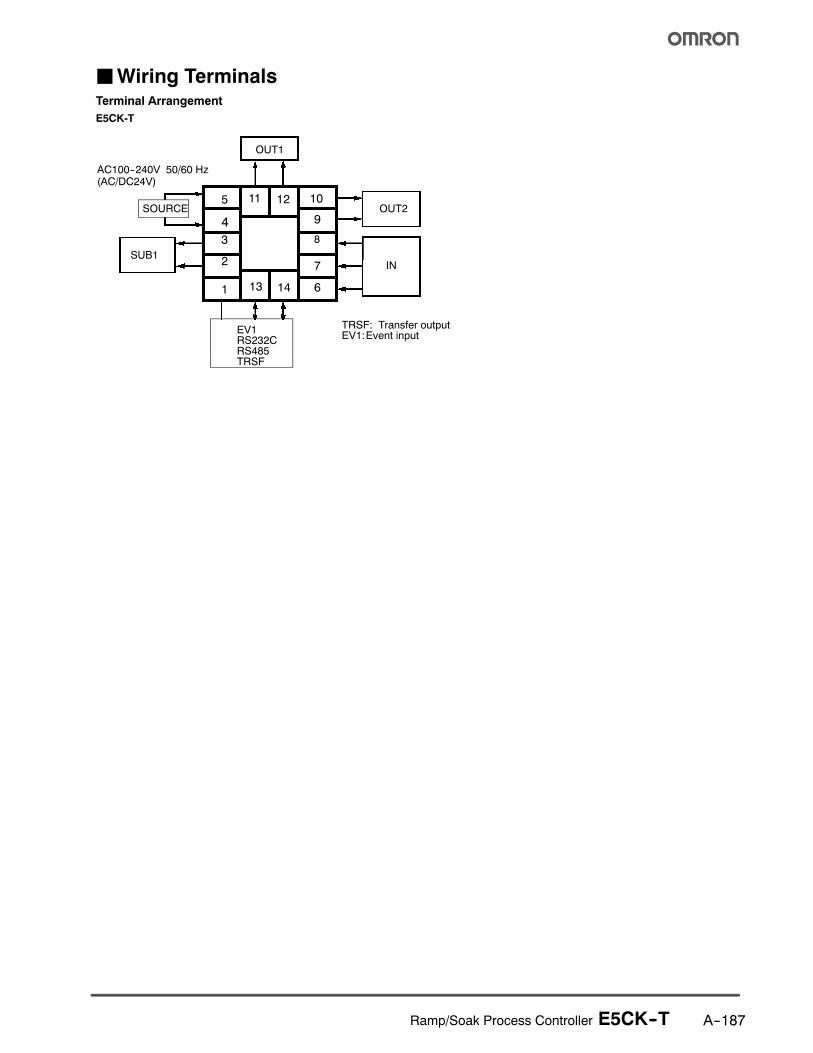
JWiring TerminalsTerminal Arrangement
E5CK-T
5
4
3
2
1
10
9
8
7
613 14
11 12
OUT1
OUT2
SUB1IN
SOURCE
EV1RS232CRS485TRSF
TRSF: Transfer outputEV1:Event input
AC100--240V 50/60 Hz(AC/DC24V)
Ramp/Soak Process Controller E5CK--TA--188
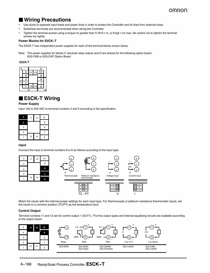
JWiring Precautions• Use ducts to separate input leads and power lines in order to protect the Controller and its lines from external noise.
• Solderless terminals are recommended when wiring the Controller.
• Tighten the terminal screws using a torque no greater than 0.78 N S m, or 8 kgf S cm max. Be careful not to tighten the terminal
screws too tightly.
Power Blocks for E5CK--T
The E5CK-T has independent power supplies for each of the terminal blocks shown below.
Note: The power supplies for blocks C (exclude relay output) and D are shared for the following option board:
E53-CKB or E53-CKF Option Board
E5CK-T
A C5
4
3
2
1
10
9
8
7
6
C
D B
11 12
13 14
JE5CK-T WiringPower Supply
Input 100 to 240 VAC to terminal numbers 4 and 5 according to the specification.
5
4
3
2
1
10
9
8
7
613 14
11 12
Input
Connect the input to terminal numbers 6 to 8 as follows according to the input type.
8
7
6
8
7
6
8
7
6
8
7
6
-
+
-
+
-
+
V mA
TC ⋅ PT V I
Thermocouple Platinum resistancethermometer
Voltage input Current input
5
4
3
2
1
10
9
8
7
613 14
11 12
Match the inputs with the internal jumper settings for each input type. For thermocouple or platinum resistance thermometer inputs, setthe inputs to a common position (TC/PT) as the temperature input.
Control Output
Terminal numbers 11 and 12 are for control output 1 (OUT1). The five output types and internal equalizing circuits are available according
to the output board.
5
4
3
2
1
10
9
8
7
613 14
11 12 11
12
11
12
L
11
12
L
11
12
L
11
12
L
E53-R4R4 E53-Q4R4E53-Q4Q4
E53-Q4HR4E53-Q4HQ4H
E53-V44R4 E53-C4R4E53-C4DR4
NPN PNP 0 to 10 V 4 to 20mA
+v+
-
+
-
+
-
+
-GND
mA
Relay
V
+v
GND

Ramp/Soak Process Controller E5CK--T A--189
Terminal numbers 9 and 10 are for control output 2 (OUT2). The three output types and internal equalizing circuits are available according
to the output board.
10
9
10
9
L
10
9
L
+V
+
-
+
-GND
E53-Q4Q4 E53-Q4HQ4H
NPN PNP
E53-R4R4 /E53-V44R4E53-Q4R4 /E53-C4R4E53-Q4HR4/E53-C4DR4
Relay
+V
GND
Specifications for Each Type of Output
Output type Specifications
RelayVoltage (NPN)Voltage (PNP)
3 A at 250 VAC20 mA at 12 VDC (with short-circuit protection)20 mA at 12 VDC (with short-circuit protection)
0 to 10 V4 to 20 mA
0 to 10 VDC, permissible load impedance: 1 kΩ min., resolution: approx. 2,6004 to 20 mA, permissible load impedance: 500 Ω max., resolution: approx. 2,600
Auxiliary Output 1
Terminal numbers 2 and 3 are for auxiliary output 1 (SUB1).
The internal equalizing circuit for auxiliary output 1 is as follows:
5
4
3
2
1
10
9
8
7
613 14
11 12
3
2
Relay specifications are as follows: SPST-NO, 250 VAC, 1 A
Option
Terminal numbers 1, 13, and 14 are valid only when the option board is set in the Controller.
The following four connections are possible depending on the model of the option board.
5
4
3
2
1
10
9
8
7
613 14
11 12 13
14
1
13
14
1
13
14
1
13
14
1
SD
RD
SG
A
B
+
--
4 to 20mA
E53-CK01
RS-232C
E53-CK03
RS-485
E53-CKB E53-CKF
Event input Transfer output
Use event inputs under the following conditions:
Contact input ON: 1 kΩ max., OFF: 100 kΩ min.
No-contact input ON: residual voltage 1.5 V max., OFF: leakage current 0.1 mA max.
The polarity for no-contact input is as follows:
13
14
1
+
--
Transfer output specifications are as follows: 4 to 20 mA, load: 500 Ω max., resolution approx. 2600

Ramp/Soak Process Controller E5CK--TA--190
Precautions
JOperating Environment• Operate the Controller within the rated ambient operating
temperature, ambient operating humidity, and storage tem-
perature ranges.
• Use the Controller according to the vibration resistance,
shock resistance, and enclosure ratings.
• Do not install the Controller in places with corrosive gas or
excessive dust.
• Do not install the Controller near machines generating high-
frequency noise.
JMounting• The dimensions of the Controller conform to DIN 43700.
• Recommended panel thickness is 1 to 8 mm.
• Mount the Unit horizontally.
JConnection• To reduce inductive noise influence, the lead wires connect-
ing the input type to the Controller must be separated from
the power lines and load lines.
• Use the specified compensating conductors for thermocou-
ples. Use lead wires having a small resistance for platinum
resistance thermometers.
JConnection Example• Wire the terminals of the Unit using solderless terminals.
• The tightening torque applied to the terminal screws of the
Unit must be approximately 0.78 N S m or 8 kgf S cm.
• Use the following type of solderless terminals for M3.5
screws.
7.2 mm max.
7.2 mm max.
JOperation• The alarm outputs of a model with an alarm function may not
turn ON correctly when the model malfunctions. The use of
alarm equipment with the Controller is recommended.
• The parameters and internal switch are set before shipping
so that the Unit will function normally. Change the settings of
the parameters and internal switch according to the
application if necessary.
• After power has been supplied to the Controller, several se-
conds are required until the relay is turned ON. Consider this
time delay when designing sequenced circuits which
incorporate a Controller.
• Do not use excessive force when removing the internal
mechanism from the housing. Protect the internal connector
or electronic parts of the Unit from shock.
• Protect against static discharge when changing the settings
of the internal switch. Changing the settings on a grounded
conductive mat is recommended.
• When connecting the control output board to the Tempera-
ture Controller or Process Controller, make sure that the
control output board is the appropriate type, or the system
may malfunction.

Ramp/Soak Process Controller E5CK--T A--191
JSSRConnection Example of Process Controller and SSR
+
--
+
--
Digital Controller
Voltage outputterminal(for driving SSR)
Connectable
Load
HeaterPower supplyfor load
Power SSR
SSR
E5jK-T
Process Controller withVoltage Output(12 VDC,40 mA max.)
See the following table.
E5CK-T
Controller withVoltage Output(12 VDC,20 mA max.)
INPUT LOAD
Model G3PA/G3PB G3NA G3NE
Appearance
SSRsconnected in par-allel
E5AK-/E5EK-T:8 pcs.E5CK-T: 4 pcs.
E5AK-/E5EK-T:5 pcs.E5CK-T: 2 pcs.
E5AK-/E5EK-T: 2 pcs.E5CK-T: 1 piece
Ratedinputvoltage
5 to 24 VDC 5 to 24 VDC 12 VDC
Features Thin, SSR with built-in heat sink;1-phase and 3-phase models
Standard model with screw termi-nals
Compact, low-cost model with tabterminals

! ! "! # # ! $ %& ''(% %%) * + !! #
! %) % *
, - ( ! ! # * ! . !% # + *
/ 011 %2 $# # * % % ! %
## !%# # 3 " $
4 . . ! # . ! ! 3 % % !! ! # !! $ ! . ! ! # . % %*
5 67 * % ! # 3 # 7* 8 ! % $ $* !"% ! ! %* * # %
9 ( & %) * .
: 6 ;) % % # % ! 38 ! !!8 % ! % ! ! % ! ! 8 3 #
1 - # < . % = % % % % * #
# * $% 6* "
% ! 8 $ * !# $ %*
- # 8 $
. ( % *
$% # % ,1 "% % # $
> &.# > + .# $% 8 # % . % ! . % '&''&?;@&A>??AB??&?&&A7A!&C?&? 7;'7&-!*<AA"7A6?7A$&;&A!;&?(DA*7'"7B ? 67A& 6? ?7(<'? <?& 6 D& $-*<B&?(@A>'&-$&D7'A&D-&&?;7A&-DD&$- >7'' <7*'B ;&& D& ?&E<7?&;&A 6 D&7?7A&A-&-<& % . % % $ " * ? + %" % * % % # "$! + ! * 3 $# # % % ! ! . $ + $ ! ! %) "!% ! ? %* % # % % % % %% $% !! % % # # ! # ! % %#
, - '&&''&?D''A*&'7*'&6?&(7'!7A-7"?&( ? (A&E<&A7' -;$&! ' 6 ?67 ? ?"-<(7A?(;;&?(7''7AAB>B(AA&(&->7DD&$-!>D&D&?<(D('7;7*&-7A(A?(!>??AB!A&$'7$&A(&??7('7*7'7B 6 ! # % . # $%
/ 7 * ! % ! ! ! . + . !# "! * + $> !* . % . % $ *
2 ( % $ .# * A" * ! .# % * $ " ! * % #
4; ># A % . % * # % % * + % * $!"#% # % # %7# # #!## # * # # !
%< % % "! % $ * + $* + 3 ! # % $% % $ % ! ! ! . % # % .# % $! % % $= ! ##
! % & !% ! !#
! 3 ! !# ! 3 !%) #
! 3 8 8% # % % $
A&F&?<&D&?-<(6?A'7(7A7AF'F7A$&?7<?7@'76&??&?B>7D<&A<?7A$DD&B&;>D'&D*&&A-&7$A&---?&D&?7@!A-DD& &''&?+ ?-<( 7 ?&?'B ?&- A- 7A''&- 6?D&7A&A-&-<&>7D7AD&F&?''&E<7;&A?B&;
% % % + "% $! 3
, - # # % 7 + ! " 3 %) +>''%
/ ( % % # 7" % % ! D # ! " $% > %! % % . %8 + # $
2 & % 8 % # % # ! % ! !

$%"=GG<"=GGG ("=GG
Cat. No. H301-E3-1 6/04 Specifications subject to change without notice Printed in USA
! "#992; # !;*2F9
$%&'&&$&(
( -# %!7'415,
$)$*)+,,6< 3 =
,,((&&)&&
- ./ 012
111# # 3H/- 2.2"/4#
!56 ## !%11,:,5# !%11,25