Embed Size (px)
Citation preview

Quick Start Guide
TWR-K70F120M High-Performance MCUs with Graphics LCD, Connectivity and Security
TOWER SYSTEM

2
Quick Start Guide
Get to Know the TWR-K70F120M
Primary Connector
Infra-Red
General Purpose Tower Plug-In (TWRPI) Socket
SW3 (Reset)
Power/OSJTAG Mini-B USB Connector
Secondary Connector
SW1
SW2
Touch TWRPI Socket
LED/Touch Buttons
E1–E4
MK70FN1M0VMJ12 Microcontroller
MMA8451 Accelerometer
1 Gb 16-bit wide LPDDR2 Memory
Figure 1: Front side of TWR-K70F120M module (TWRPI devices not shown).
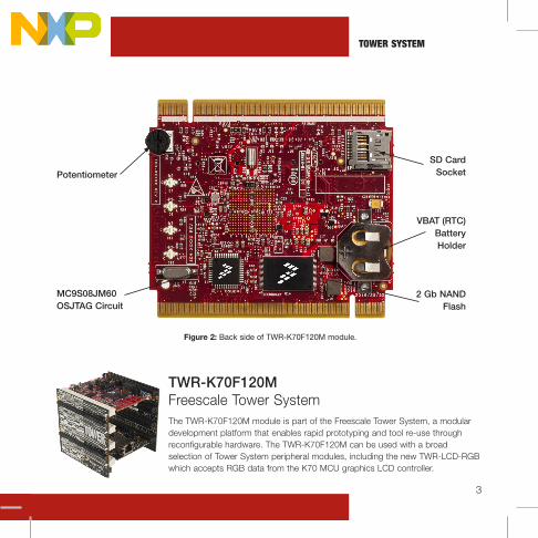
Figure 2: Back side of TWR-K70F120M module.
3
TOWER SYSTEM
TWR-K70F120M Freescale Tower SystemThe TWR-K70F120M module is part of the Freescale Tower System, a modular development platform that enables rapid prototyping and tool re-use through reconfigurable hardware. The TWR-K70F120M can be used with a broad selection of Tower System peripheral modules, including the new TWR-LCD-RGB which accepts RGB data from the K70 MCU graphics LCD controller.
Potentiometer
MC9S08JM60 OSJTAG Circuit
Figure 2: Back side of TWR-K70F120M module.
SD Card Socket
VBAT (RTC) Battery Holder
2 Gb NAND Flash

4
Quick Start Guide
TWR-K70F120M Features
• MK70FN1M0VMJ12 MCU (120 MHz, 1 MB flash, graphics LCD, Ethernet, USB OTG, tamper detection, encryption, NAND flash and DDR controller, 256 MBGA)
• Interfaces to the new TWR-LCD-RGB Tower peripheral module (accepts RGB data directly from the K70 MCU LCD controller)
• MC9S08JM60 open source JTAG (OSJTAG) circuit
• Micron MT47H64M16HR-25 1 Gb 16-bit wide LPDDR2 memory
• Micron MT29F2G16ABAEAWP 2 Gb NAND flash
• Four user-controlled status LEDs
• Four capacitive touch pads and two mechanical push buttons
• General-purpose TWRPI socket (Tower plug-in module)
• TWRPI-TOUCH-STR socket (touch-sensing Tower plug-in module)

5
TOWER SYSTEM
Step-by-Step Installation Instructions
Install the Software and ToolsInstall the P&E Micro Kinetis Tower toolkit. The toolkit includes the OSJTAG and USB to serial drivers. These can be found on the DVD under Software.
Configure the HardwareInstall the included battery into the VBAT (RTC) battery holder. Then, connect one end of the USB cable to the PC and the other end to the Power/OSJTAG mini-B connector on the TWR-K70F120M module. Allow the PC to automatically configure the USB drivers if needed.
Tilt the BoardTilt the board side to side to see the LEDs on E1–E4 light up as it is tilted. While the board is held flat, touch the pads on E1–E4 to toggle the LEDs.
Play the Memory GamePress SW2 to play a memory recall game using the touch pads E1–E4. A sequence will light up, then press the touch pads in the order flashed. If an incorrect sequence is touched or too much time has elapsed, all the lights will blink rapidly and the game will reset.
Press SW1 to return to the accelerometer demo.
1
4
3
2
TWR-K70F120M Features

6
Quick Start Guide
TWR-K70F120M Jumper OptionsThe following is a list of all jumper options. The default installed jumper settings are shown in white text within the red boxes.
Download the TWR-K70F120M User Manual and Demonstration LabsDownload the TWR-K70120M user manual and demonstration labs at freescale.com/TWR-K70F120M.
Jumper Option Setting Description
J8 MCU Power Connection ON Connect on-board 3.3-volt supply to MCU
OFF Isolate MCU from power (connect an ammeter to measure current)
J20 MCU VDD_INT Power Connection
ON Connect VDD and VDD_INT rails together
OFF Isolate MCU VDD_INT from power (connect an ammeter to measure current)
J17 VBAT Power Selection 1-2 Connect VBAT to on-board 3.3-volt supply
2-3 Connect VBAT to the higher voltage between on-board 3.3-volt supply or coin-cell supply
Download the Freescale CodeWarrior IDE and MQX™ RTOSDownload the Freescale CodeWarrior IDE and MQX RTOS by clicking on the relevant links on the Software tab of the Tower Kit DVD.
5 6

7
TOWER SYSTEM
TWR-K70F120M Jumper Options (continued)
Jumper Option Setting Description
J8 MCU Power Connection ON Connect on-board 3.3-volt supply to MCU
OFF Isolate MCU from power (connect an ammeter to measure current)
J20 MCU VDD_INT Power Connection
ON Connect VDD and VDD_INT rails together
OFF Isolate MCU VDD_INT from power (connect an ammeter to measure current)
J17 VBAT Power Selection 1-2 Connect VBAT to on-board 3.3-volt supply
2-3 Connect VBAT to the higher voltage between on-board 3.3-volt supply or coin-cell supply
Jumper Option Setting Description
J18 Oscillator output enable OFF 50 MHz oscillator output enabled
ON 50 MHz oscillator output disabled
J10 OSJTAG Bootloader Selection
ON OSJTAG bootloader mode (OSJTAG firmware reprogramming)
OFF Debugger mode
J19 50 MHz Oscillator Power
ON ON = on-board 50 MHz oscillator powered
OFF OFF = on-board 50 MHz oscillator not powered*
J12 JTAG Board Power Connection
ON Connect on-board 5-volt supply to JTAG port (supports powering board from JTAG pod supporting 5-volt supply output)
OFF Disconnect on-board 5-volt supply to JTAG port
J2 IR Transmitter Connection
ON Connect PTD7/CMT_IRO to IR transmitter (D1)
OFF Disconnect PTD7/CMT_IRO from IR transmitter (D1)
J16 IR Receiver Connection ON Connect DAC1_OUT/CMP2_IN3 to IR receiver
OFF Disconnect DAC1_OUT/CMP2_IN3 from IR receiver
J1 VREGIN Power Connection
ON Connect USB0_VBUS from elevator to VREGIN
OFF Disconnect USB0_VBUS from elevator to VREGIN
*NOTE: This option must be selected whenever a Tower System module card that provides a clock on primary elevator pin B24 is connected to the CPU module.

For more information, visit freescale.com/Tower
Join the online Tower community at towergeeks.orgFreescale, the Freescale logo and CodeWarrior are trademarks of Freescale semiconductor, Inc., Reg. U.S. Pat. & Tm. Off. All other product or service names are the property of their respective owners. © 2012 Freescale Semiconductor, Inc.
Doc Number: TWRK70F120MQSG REV 1Agile Number: 926-78651 REV B
Visit freescale.com/TWR-K70F120M, freescale.com/K70 or freescale.com/Kinetis for information on the TWR-K70F120M module, including:
• TWR-K70F120M user guide• TWR-K70F120M schematics• Tower System fact sheet
SupportVisit freescale.com/support for a list of phonenumbers within your region.
WarrantyVisit freescale.com/warranty for complete warranty information.
Quick Start GuideQuick Start Guide


![QUICK MENU [4] DISABLE CANCEL QUICK MENU [1] THU CH5 …konics.co.kr/upload/data/KRN100_KEP-K-0121_20150416_W.pdf · quick menu [3] quick menu [1] quick menu [4] disable cancel quick](https://img.dokumen.tips/doc/110x75/5a9da0aa7f8b9a21688d17b5/quick-menu-4-disable-cancel-quick-menu-1-thu-ch5-menu-3-quick-menu-1.jpg)