Embed Size (px)
Citation preview

DEC. 1945
1/6 Vol. LI. No. 12
-
IN THIS AC /DC QUALITY AMPLIFIER ISSUE :

Advertisements Wireless World December 1945
IN 1...w. ..twrs. In . n.r. ... : en MIMI w::::u .wi.:üi :u..u.N:Ó . .w.wuN :.lin .. Y ..w. W W 2:i.i liuuw.NO. =
I
N......w1 .... u. .w :i::.iiiwsi: .iii u.w1u.. =ME -:GÜ-::=ai:3 iißiü f=: u.=.Ní iiiiwsniiirieeüiw. .ii: i:{: 1 w.. .
1 .NI\... NNW i:: . .
i
... .N 1,11
11 11
,r4i6i. tttt1
F:=1 1! ,
TS-
i
i ieiiuuu3
f1:ll::: i
Components Tte 6ttye
made by the organisation with the greatest experience
n
,,..%: a.,rorn-.
:..1..:..`._.:.. o..i... O.u.Nu .nu öiu::i tC Inn .It N
LIMITED :I:::
.... N...'
uni .wr BRITISH GEORGIAN HOUSE, BURY STREET, ST.JAMES'S
LONDON S.W.I. ENGLAND
Robert Sharp & Partners

December 1945 Wireless World
Rpd. Trade Mark
PRECISION
TESTING INSTRUMENTS
HIGH accuracy, simplicity, excep-
tional versatility and proven reliability have won for " AVO " Instruments a
world-wide reputation for supremacy wherever rapid precision test work is
demanded. There is an " AVO " Instru- ment for every essential electrical test.
Sole Proprietor, cased Manufaetwere THE AUTOMATIC COIL WINDER & ELECTRICAL EQUIPMENT CO. LTD., Winder House, Douglas Street, London, S.W.I. 'Phone: VICtoria 3404 18
Advertisements i
The MODEL 7 50 -Range Universal
AVOMETER Electrical Measuring Instrument
A self- contained, precision moving -coil instrument, conforming to B.S. sot Grade accuracy requirements. Has 5o ranges, providing for measuring A.C. & D.C. volts, A.C. & D.C. amperes, resistance, capacity, audio -frequency power output and decibels. Direct readings. No external shunts or series resistances. Provided with automatic compensation for errors arising from variations in temperature, and is protected by an automatic cut -out against damage through overload.
A111II
I
a...., 9f Ko216 lfy, G140;,'é;j?,'iil20 pf;2
Illlimni For Peak Performance
u
1
0/4 4# //a&yr U.I.C. Fixed Ceramic Pot and Plate
Capacitors have been primarily developed for use in transmitter circuits. Made only from the highest grade raw materials and subjected to the most rigorous mechanical and electrical inspection, their performance especially with H.F. loads and high voltages is unsurpassed. TYPE APPROVED. Full details on request.
CERAMIC 0°4-0- - iYde yy
CAPACITORS UNITED INSULATOR CO., LTD., 12.22 LAYSTALL ST. LONDON, E.C.I.
Tel. TERminus 7383 (5 lines) Grams: Calanel. Smith, London

2 Advertisements
Technical Reasons Why
Is the Finest Cored Solder in the World
3 CORES OF FLUX
Three Cores of Flux ensure flux con- tinuity. No lengths without flux are wasted. Consistent high quality joints are obtained with comparatively unskilled labour. Exactly the correct proportions of solder to flux are provided. Separate fluxing operations are obviated and no extra flux is required. The three cores of flux being evenly distributed over the cross section of the solder provide thinner
solder walls than otherwise. This gives rapid melting and
speeds up soldering. The flux does not tend to run out of
the cores ; so there is always a supply available for the next joint. The utmost economy of solder and flux is achieved.
Ersin, contained in the three cores of Ersin Multicore Solder, is the fastest non- corrosive flux. Possessing all the non- corrosive advantages of rosin, it enables joints to be speedily made on oxidised or difficult " surfaces such as nickel. Ersin not only avoids oxidation during soldering but removes surface oxide already present -this is particularly advantageous in respect of materials that
have been in stock or apparatus that is being serviced. The use of Ersin Multicore, with correct soldering technique, avoids " HR " or dry joints.
Ersin Multicore Solder is made in most gauges between IO and 22 S.W.G. ( 128 -028 ") (3251 -7109 m; ms). For general radio and electrical production and maintenance 13 and 16 S.W.G. are in most demand.
Five alloys of Ersin Multicore Solder, made
Virgin from virgin metals, are available -all
Tin &Lead antimony free. Under present circum- stances 45% tin and 5S°ß lead is the most widely used alloy.
Technically, Ersin Multicore Solder other cored solder. A practical laboratory or production test will demonstrate this and show you that it is the most economi- cal solder to use. The majority of British and overseas manu- facturers already enjoy the advantages of Multicore. If you do not, and are engaged upon Government contracts, write for further technical information and free samples
is far superior to any
Single reel rate nominal 1 lb. reels.
13 SWG - 4/10 16 SWG - 5/3
Above prices subject to usual trade discount.
} cwt.- ton lots at bulk rate. 6d. cartons for home use, available at most good radio and electrical dealers, ironmongers, etc.
MULTICORE SOLDERS LTD. Mellier House, Albemarle St., London, W.I.
Tel.: REGont 1411 (P.B.X. 4 Lines).
Wireless World December 1945
Slow- Motion Dials High grade reduction drives have been in short supply. We can now offer famous Burndept slow- motion dial, dual ratio, panel mounting instrument type, calibrated
12,6 degrees, 31in. overall diameter ..
Four -Gang Condensers Ceramic insulation, 300 m.mfd. per sec- 17
Ó tion, capacity increases anti -clockwise
EDDYSTONE Specialised radio components are now becoming easier in supply. New designs keep EDDYSTONE the pre- eminent name In Short -wave technique.
Flexible Driving Shaft Type 5530. Frequentite insulation, drives through 90 deg. Length adjust- able between 41in.and 6in. .. .. .. 5i-
H.F. Chokes Type 1010. The best S.W. choke,
5;180 metres ..
Type 1022. Transmitting 250 m.a.
Type 1011. U.H.F., 2.5 to 12 metres . .
Type 1066. All Wave Choke. 12.5 to 2,000 metres ..
2/- 3/- 1/6
2/9
Neutralising Condensers Type S481. New and compact design, size I }in. x tin. x I }in. high. 1.5 to 4
m.mfd., Frequentite insulation, silver plated brass. 2,000 v. R.M.S. max. .. 3/6
Insulators Type 916. Beehive type stand -off .. 1/3
Type 999. Aerial, low leakage type 1/- Type 1019. Midget stand -off .. .. 6d.
Type 1018. Cone type lead through .. 1/3
Temporary leaflet showing other available EDDYSTONE components 21d. post free.
14 Soho Street, Oxford Street, London, W.I
Telephone : Gerrard 2089
we are available 4 a.m. till 6 p.m. for OFFICIAL business, but please note our revised SHOP HOURS -9 a.m. to
I p.m. weekdays. (Saterdays 9 a.m. to I p.m.)
December 1945 Wireless World Advertisements 3
o
en Si' ronds Count... _-
o o
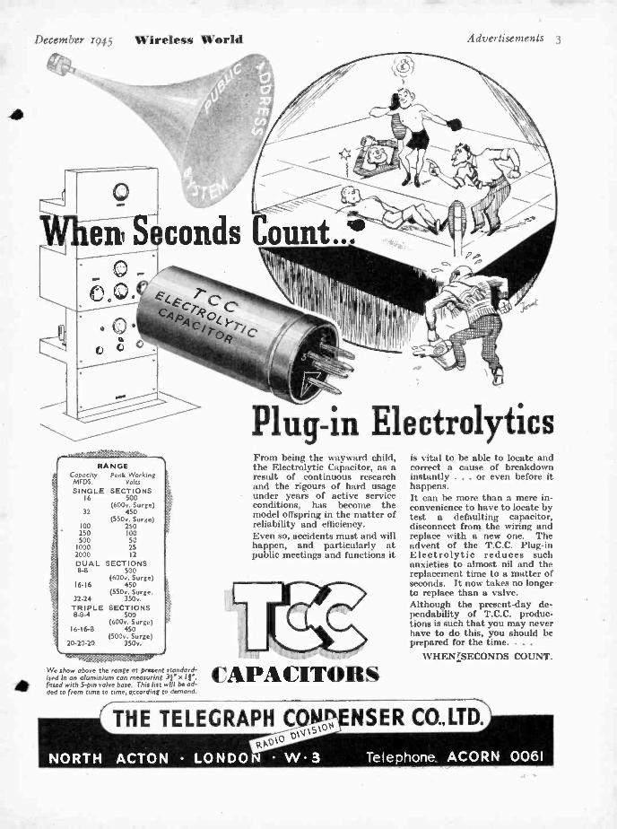
RA NGE Capacity Peak Working MFDS. Volts
SINGLE SECTIONS 16 500
(600v. Surge) 32 450
(550v. Surge) 100 250 250 100 500 50
1000 25 2000 12
DUAL SECTIONS 8-8 500
(600v. Surge) 16-16 450
(550v. Surge, 32-24 350v. TRIPLE SECTIONS 8-8-4 500
(600v. Surge) 16 -16-8 450
(500v. Surge) 20-20 -20 350v.
k
We show above the ronge at present standard- ised In an aluminium can measuring 3I' x 1l', fitted with S-pin valve base. This list will be ad- ded to from time to time, according to demand.
Plug -in Electrolytics From being the wayward child, the Electrolytic Capacitor, as a result of continuous research and the rigours of hard usage under years of active service conditions, has become the model offspring in the matter of reliability and efficiency. Even so, accidents must and will happen, and particularly at public meetings and functions it
CAPACITORS
is vital to be able to locate and correct a cause of breakdown instantly ... or even before it happens. It can be more than a mere in- convenience to have to locate by test a defaulting capacitor, disconnect from the wiring and replace with a new one. The advent of the T.C.C. Plug -in Electrolytic reduces such anxieties to almost nil and the replacement time to a matter of seconds. It now takes no longer to replace than a valve. Although the present -day de- pendability of T.C.C. produc- tions is such that you may never have to do this, you should be prepared for the time. . . .
WHENLSECONDS COUNT.

4 Advertisements
gx.
TAYLOR A.C. BRIDGE MODEL naa
These instruments give quick and accurate measure-
ments of Capacity and Resistance. There are six
Capacity ranges covering from .00001 to 120 mfd. and
the Power factor can also be measured on each range.
Six Resistance ranges are available measuring from
I ohm to 12 megohms. This bridge is A.C. mains
operated and a leakage test is also available for detecting
leaky paper or mica condensers. Price E14 I4s. Od.
Please write for technical leaflet.
Wireless World December 1945
6 RANGES OF CAPACITY RANGES OF RESISTANCE
Send your enquiries to :- TAYLOR ELECTRICAL INSTRUMENTS LTD
cì. o r electrical
419 -424 MONTROSE AVE., SLOUGH, BUCKS. Tel: Slough 21381 (4 lines) ' Grams: "Taylins ", Slough.
31" unit 9,Òe0 lines. kArkdiJe
LOUD SPEAKERS
These two units, although so diff- erent in size, have much in common. Both are fitted with new high- effici- ency Magnets, and die -cast, rustless, non - resonant chassis with accurate rear - suspension and both .. . .
are Wharfedale products. W.12
13,000 LINES 130r-
MADE AND GUARANTEED BY
WHARFEDALE WIRELESS WORKS SOLE PROPRIETOR: D. E. BRIGGS
HUTCHINSON LANE, BRIGHOUSE,YORKS. 'PHONE: BRIGHOUSE 50. 'GRAMS: ' WHARFDEL."
5 V TC N uL ZCe
Manufactured by
BRITISH ® CO., LTD. K E I G H LEY YORKSHIRE London Once: 25, MANCHESTER SQUARE, W.I 'Phone: Welbeck 7941 'Grams : Enesef, London

December 1945 Wireless World Advertisements 5
Is your showroom "Skyrod" working... ?
"SKYROD"
* TELEVISION Aerials
ma-trio pia alrrl
111.11,..311
aum!il
IPII...2 Iriqlul :..
f; 'MI !TRW U I
N ono WJIIII W...II-
SNI IIW I IIIIIIIIII IIWIIIII T-.77
AArss l a i r e eal
INTERFERENCE Suppressors
AT last we are able to offer our range
of aerials and suppressors. They are
not yet in stock all over the country, but
difficulties are being overcome.
Dealers . . . are your "Skyrod" and
Television Aerials ready for showroom
demonstration ? Those of you in the area
served by the Alexandra Palace transmitter
should check up, or get in touch with us.
BELLING&LEE LTD CAMBRIDGE ARTERIAL ROAD. ENFIELD. MIDDX
GA

6 Advertisements
MARCONI ST. ALBANS, HERTFORDSHIRE
Wireless World /h rnrbrr ,
till g,.. U ___ __
ems -
In communications, wherever measurement for testing
purposes is involved, empiricism can be ruled out. Of no
avail without scientific instruments is anything the eye can
see, the hand feel or the most observant remember. The radio engineer, therefore, must have test gear on which he
can rely and, thanks to the foresight of Marconi
Instruments Ltd., has a wide selection from which to
choose. And he finds exemplified in these Marconi
products the qualities so characteristic of British engin-
eering craftsmanship -rational design, precise workmanship
and technical efficiency.
INSTRUMENTS, LTD Telephone : St. Albans 4323 -6
COSMOCORD LTD ENFIELD
M.G.1, 2 or 3 GANG
CONDENSER This small size condenser is of rigid construction, and is made in various capacities up to 540mmf. with tropical finish. It can be supplied with trimmers built in if required. The 2 Gang Frame is 21 "xl; ;y "x2;',;" over all.
JACKSON BROS (LONDON) LIMITED
1 D 1 KIN WADDON SURREY A TELEPHONE. TELEGRAMS: WALFILCO. Y CROYDON 2754 -5 PHONE. LONDON

December 1945 Wireless World Advertisements 7
4;400- THE COUNTERSIGN OF DEPENDABILITY IN ANY ELECTRONIC EQUIPMENT 'CJ SS
Front ri. w of the 23,} watt, 1la tnc. Motorola transmitter. now gi,- ing Mimi police toe
learnt rf coverage for a radios of 30 miler.
Pa- IN FM POLICE SYSTEMS
EIMAC TETRODE 4 -125A
Top honors to Galvin Manufacturing Corporation for building it, and a salute to the police and fire departments of Miami, Florida, for putting it to work in spite of the skeptics! Its the first two -way police radiotelephone system in the United States on frequencies above too me.
Twenty -four hours a day, 12 patrol cars in Miami's busy area tune in on signals as solid as a dinner table conversa- tion from this Motorola 250 watt, 118 mc. FM transmitter.
From the earliest experimental stages of FM broadcast. ing, Eimac valves have been lending a hand. Naturally, there are Eimac 4.125A tetrodes (pictured above) in the vital power output stage of Galvin's new Motorola success. Eimac 4.125A's were a logical choice for this transmitter because of their superlative high frequency performance capabilities and their low driving power requirements.
FOLLOW THE LEADERS TO Arb for 'owe cop of E/ettnole T.l.t.t. tb. Ob. page booklet ern tog Me I oda tal( of lern .t .n,. It well kelp el...
t.err rngse.rn .,:plato the ..hl.a to o. Are, labte to iów md obl ao o/ tower.
Ne
IITII- M.CYllOUIN, Im.. 1074 fa. Mates A . fan Irene. Colle.
Mots laeted at: ion Irene. Calllarnie and 0 11 labe Cite. Utah
lptt Agents: From I Hon..., 701 Cloy It., san (tontine 11. Celit., U. 5. A.
ELECTRICAL CHARACTERISTICS- 4 -125A TETRODE
f dament. Thoriated tungsten 0(.0,11 le.trodeCopxit (Average(
Voltage . S 0.01.. God Plate (Without shielding,
Current a 2 ampere* base grounded) . . . . 0030u14.
Plot. D,,pot.cn Input 10 7 .old. . IM a.,muml 125 watt. Oelpet 7 0 sold.
Iron.tondoelonte i,. 0 50 me. Is = 2500.. 1,l =400 ..I . 2450 .0hae
Authorised. Distributors: BERRY S (SHORT -WAVE) LTD., 25 HIGH HOLBORN, LONDON, W.C.I.

8 Advertisements
The GOODMANS
I RANGE Includes Loudspeakers from 21 dia. (I watt output) to 18 in. cone
models and Industrial Types up to 20 watts output.
i
Wireless World December 1945
u y Lll' y lot TOMORROW.... ,
THAT tomorrow must be taken care of today has always been Goodmans I policy. Constantly thinking and planning ahead Goodmans inevitably
found themselves leaders in the field of Sound Reproduction. As a result, during the past critical years Goodmans have been entrusted with many onerous tasks in the designing and production of Loudspeakers, Microphones, and Earphones. True to their policy Goodmans tested and sifted to build data which might serve in the days to come. Now Goodmans stand ready to give of their greatly enhanced knowledge to the no less onerous tasks of Peace.
The TYPE T2 /I2. Overall Dia. 1233/8 in. Voice Coil Impedance 15 ohms at 400 C.P.S. Power Handling Capacity 12 w. Peak A.C. on flat 4 ft. baffle (15 w. horn loaded). Flux. Density 13,000 gauss.
c000r>aans
GOODMANS INDUSTRIES LTD LANCELOT R D WEMBLEY MIDDX
DELIVERY EX STOCK (subject to
being unsold on receipt of order).
WESTINGHOUSEM*
METAL RECTIFIERS TYPES LT.41, LT.42, HT.41 & HT.42
TYPE OUTPUT
PRICE VOLTS AMPS
LT.41 12 I 27/-
LT.42 6 I 2I/-
HT.41 200 0.1 25/-
HT.42 450 0.1 38/6
Subject to alteration without notice.
Write for details to Dept. W.W.
WESTINGHOUSE BRAKE & SIGNAL CO., LTD. Pew Hill House, Chippenham, Wilts.
M.R. SUPPLIES of the following brand -new and first-class RADIO and ELECTRICAL MATERIAL from stock. Prompt despatch. All prices nett. ROTQEEMZ =BRUSH PIEZO- CRYSTAL MICROPHONES. Resumption of our former popular offer of D.104, specially housed with knuckle-joint mount (for angle adjustment) and with Eft. screened lead. To -day', greatest value In "quality" microphones, 7816. STANDS to suit, Table model, all chromium, extending. 2916. Collapsible Floor model, ext. to 5ft. 615. and folding to 2ft. all chrom., 47/6. P.A. PROJECTOR SPEAKERS (we are large stockists of this equipment). Latest Vitavox 10 -watt P.M. Unit (15 ohms) with 30 -Inch all -metal square projection Horn. spec. offer. 29 10s. (deep. 7/6). Or with 42 -Inch all -metal round projection Horn, £10 10s. (deep. 7/61. Also new O.E.C. type "A" Unit (10 watt, 16 ohms) with line transformer incorporated, on 30 -Inch Horn (a above), LU (dap. 7/6). On 42-inch Horn (a above). £12 (deep. 7/6). Immediate despatch. HIGH- FIDELITY M /COIL SPEAKERS. The celebrated Vitavox K12 /10 (10 watts, 15 ohms coli) fitted high-efficiency 'Moral Magnet. 12 -inch die.. £7. Also the 1112/20 (same spec. handling 20 watts(. £11 (deep. either 5 /.1. We also supply from stock the amazing new Vltavoz " Bltoue" Speaker comprialog 12.inch p1 -fi F.M. Unit and special " Tweeter " P.M. Unit with 6-cell horn and Hater. all in massive grey-enamelled cabinet 32 by 17 by 15 Inches, £31 10s. (ex till. address, or we CAD
quote for despatch). B.T.C. METAL RUMMERS for max. 12 -volt charge at 6 amps, 39/6. Same voltage, 10 amps, 49/6 (deep. either 2/ -). Also email relay- operating or bps B.T.C. Rectifiers, delivery 26 v. 75 m.a., 61 -. STEP -DOWN MAINS TRANSFORMERS. 200/240 v. (tapped) to 5, 12 and 17 v. at 0 amps (suitable for 6 -coup Rectifier, above), 49/6 (deep. 2/ .). Also 200 /240 v. (tapped) to 7. 11 and 15 v. at 2 amps, 20/ -. Also 200 /240 v. (tapped) to 22 v. at 2 amps. 18/6. HEATER TRANSFORMERS. 220 /230 v. to 6.3 y. 1 amp and 5 v. 1 amp, 17/6. SLIDING BESIBTAACES, all fully enclosed and constantly rated. 100-watt range 4 ohms 6 amps, 10 ohms 3 amps. 60 ohms 1.4 amp. 100 ohms 1 amp, 200 ohms 0.7 amp and 400 ohms 0.5 amp, any one 26/ -. Alan 160 watts, 1100 ohms 0.375 amp, 29/6. DIMMERS for Stage Lighting, controlling stated load from full- bright to blackout (220/240 v.) with slow motion drive and handwhee1, 5000 watts, £612..6d.; 1500 watts, £8 8.. ; 2500 watts. £9 17.. 6d. (dap. either 7/6 plus 20/. for returnable saw). L.Y. CHOKES, 10 henry 150 ma. (160 ohms), 18/6 ; 16 henry 100 ma. (320 ohms),
MAINS TRANSFORMERS, tropical epee., per cent. o4er.oCT. Prim. 1801250 v. (tapped). Bray.: 300/0/300 v. 60/76 m.a., 6.3 v., 1.6 a., 4 v. CT. 2.6 a.a m mat brackets with terminal board, 35/ -. Also name spec. Prim. : 180/260 v. (tapped); Sec. : 120 and 160 v. at 400 m.a.. 2916. TRANSFORMER BOBBINS, standard replacements for many popular receivers. Core opening 11 eq. and 11 through. ('rim. 200 /240 y. (tapped); Secs. : 360/0 /360 v. 76 m.a., 4 v. 6 a., and 4 v. 3 a., 18 /6. HEAVY DUTY OUTPUT TRANSFORMERS. W.W." epee., handling 25 watt., 11 ratio. from 12/1 to 76/1 with C.T. for push -pull and tapped we.. weight 91 lb... 59/6 (dap. 2 /-). There I. no better output trausformer. PRECISION MEASURIBO INSTRUMENTS, awn mtg.: 011 m.a. 2iln. 4916. 311e.
63 / -. 0/600 microamp.. 3í1n. 69'6. PORTABLE CODED IISTRUI KNTS in crahproof bakellte case. 6 by 4 by 3 Ina.. with handle. 1000 ohms /volt, AC /DC reading. m.a. 0 /1. 0/10. 0 /100, 0 /600. volts, 0 /10. 0/50. 0 /100 and 01600, ohms, 0/5000 £6 17.. 6d.
(Guaranteed product. of British Physical laboratories.) Flame include sufficient for despatch where not stated.
M.R. SUPPLIES, 68, New Oxford Street, London, W.C.1 (Telephone : MUSeum 2958)

December 1945 Wirrlcccs World Advertisements 9
POLYETHYLENE MOULDED CONNECTORS
Pressure moulded by a new process that cannot yet be described in detail, these fittings are terminations and connec- tions used in electronic circuits. The production of these polyethylene mouldings in quantity is the result of a new manufacturing technique successfully evolved by this company.
BRITISH INSULATED CALLENDER'S CABLES LIMITED NORFOLK HOUSE, NORFOLK STREET, LONDON, W.C.2

io Advertisements
STATIC TWO - DIMENSIONAL visual delineation of any recurrent law. RELATIVE TIMING OF EVENTS and other comparative measure- ments with extreme accuracy.
PHOTOGRAPHIC RECORDING of transient phenomena.
SIMULTANEOUS INDICATION of two variables on a common time axis. INDUSTRIAL INDICATING and TESTING afford in-
creasing scope for the Cathode Ray Tube as the only
device with the above inherent features of which the
last is unique in the Cossor DOUBLE BEAM Tube.
The Model 339 Cossor Oscillograph thus equipped
is invaluable on all problems of research, production or operational testing, when the effect examined is
applied as a voltage. When recurrent the traces are
studied visually and when transient are recorded
photographically, using Model 427 camera.
A. C. COSSOR LTD., INSTRUMENT DEPT.
Cossor House, London, N.5. 'Phone : CANonbury 1234 (33 lines). 'Grams: Amplifiers Phone London.
gr-
Wireless World December 1945
THERE ARETRIX ANN PIERS
FP. PRIOR
500 V A
SFOP
THE TRIX ELECTRICAL CO,LTD. 5.5. NNAIPRE PLACE. TOTTEMNAM Cl. RD.
LONDON. W. I,.... Ml.)!1' ',Ai; 6s. --"Adel TA t11110 MPSDO.t ONDOSI.
TYPE S.__C.
6 LINEAR CAPAC'TY
19
eaaeitoid SYDNEY S. BIRD & SONS LTD.
CAMBRIC:E ARTERIAL ROAD. ENFIELD.

December 194.5 Wireless World Advertisements I I
Made in Three Principal Materials
FREQUELEX An insulating material of Low Dielectric Loss, for Coil Formers, Aerial Insulators, Valve Holders, etc.
PERMALEX A High Permittivity Material. For the construction of Condensers of the small- est possible dimensions.
TEMPLEX A Condenser material of medium per- mittivity. For the construction of Condensers having a constant capacity at all temperatures.
'Bullera B U L L E R S LOW L O S S C E R A M I C S
B U L L E R S LTD., 6 , L A U R E N C E P O U N T N E Y HILL, LONDON, E. C. 4 Telephone : Mansion House 9971 (3 lines) Telegrams : ' Butlers, Cannon, London " Manchester Office : 196, Deansgate, Manchester

12 Advertisements Wireless World December 1945
-pSSO qyP
Idyl P
LASSO is making a mark for itself
Lassu Self- Adhesive Tape solves all your marking problems. These brilliant filmic markers can be cut off to length desired, are easy to apply, are ever -legible and are impervious to heat and fluids. Supplied in 10 -yard rolls or individual labels, in colours to B.S. Specification and in shades matched to customers' requirements. Any type of wording, letter- ing or diagram produced.
IDENTIFICATION :
Numbering of parts to simplify assembly of com- plicated circuits. Stores reference
numbers. e te
m
gMP ,
S No ,---
,,.
INSPECTION : ÿ TED ;' Pp=''
AC71VA `
Facilitates in- ,---"` - , 6) spection by indi- eating treatment of components.
.c.
a,:`` , SPE I0401C
ai
il
la
- HEAT TREpTE `'I
ÑOtI 00,11= - C SPlttry. t - --.
INSTRUCTIONS : ., Í OO NOT N Labels with details for fa_'I ' ? ' er TNIS C
sembly work or ty f v finished comp"- i ' ' DO f101 LAR
CfAt\ HANDLE LIKE EGGS_,
NAME TAPES: Ideal for sealing and labellin:: packages or finished compo- nents with your name.
r,RUNOr L,D
GRusol liti.
PERIBRAID"I Grade " C
DGO.W7 Spec
corpsrrLreNO . .. .
e.., CAr nun*"
iiii<.i:i3333üilaii:ks:ccn:c:::aNiRiiRi,H#
GRUNpy ut. GRUNDY up. ,--.-
Nptf
oDst`1 Full details from CABLE ASSEMBLIES LTD. (Subsidiary of Herts Pharmaceuticals Ltd.) BESSEMER ROAD, WELWYN GARDEN CITY
C) Telephone: Welwyn Garden 3333 6 Telegrams: Cablsembly, Welwyn Garden City
Designers and Manufacturers of Radio
and Electronic Devices.
ROMAC RADIO CORPN. LTD.
Announce a range of AMPLIFIERS
12 watts -25 watts, built to a
quality specification as regards
performance, construction and to meet the requirements of the discerning purchaser. Full details,
specification, price on request. The above can be delivered with Speakers, Microphones and Turn- table units if required.
THE HYDE ' HENDON LONDON, N.W.9
. +
+ THE STATIC +
+
+
+
+
+
+ *Manufacturers of
+ STATIC + CONDENSERS
+
+
+
+
+
+
-0- -0-- -4e- -0- -0- -0- -0-.;. +
CONDENSER Co. Ltd.
TOUTLEY WORKS, WOKINGHAM, Berks
Telephone : WOKINGHAM 708
:.« +.... +

December 1945 'n'ircIc ss U'orld
WORLD'S LARGEST RADIO
COIL MANUFACTURERS RADIQ FREQUENCY INDUCTORS INTERMEDIATE FREQUENCY
TRANSFORMERS RADIO FREQUENCY CO'L
CHOKES MICA COMPRESSION
CONDENSERS AIR DIELECTRIC CONDENSERS MICA MOULDED CONDENSERS SICKLES SILVER CAP
CONDENSERS GANGED PERMEABILITY TUNING COMMUNICATIONS EQUIPMENT F.M. EQUIPMENT PARTS U.H.F. RADIO EQUIPMENT SPECIAL ELECTRONIC
EQUIPMENT
The F. W. SICKLES Co. CHICOPEE, MASS., U.S.A.
RAYTHEON "FLAT" Hearing Aid Tubes
So tiny they must be built under a high powered magnifying glass . .
just as a jeweller assembles rare gems in a costly brooch. They're the hearts of famous hearing aids, providing ut- most clarity and richness of tone.
RAYTHEON MANUFACTURING COMPANY
NSA.INO AID TUBE DIVISION N.., Maa.A.,.,l,
P. R. M IIORY tì. CO. Inc.
Y MALLORY VIBRATORS ARE ALWAYS DEPENDABLE
Along every front Mallory has pioneered in Vibrator design to ensure safety, depend-
ability and long service. Mallory offers syn- chronous and non- synchronous Vibrators for 6, 12 and 32 volt input, also a complets: range of "STRATOSPHERE " Vibrators plu. the world- fafnous Mallory " VIBRAPACK (Reg. Trade Mark).
* Vibra pack is a registered trade mark, the property of P. R. Mallory & Co., Inc. Indianapolis, U.S.A. Units which do not bear this trade mark ore not o {enuine Mallory manufacture.
P. R. MALLORY & CO. INC. INDIANAPOLIS, INDIANA,
U.S.A. Radio and Electronics Division
ALSO
"MYKROY" CERAMIC INSULATING MATERIALS GENERAL ELECTRONIC VACUUM CONDENSERS
FOR THE FUTURE These Manufacturers will help solve you post -war problems. Register your name now for full details which will be sent you when supply conditions again permit.
FAN1( ll'V!EÍR LIMITED
Kingsley Road, BIDEFORD N. Devon
Advertisements 13
VICTORY PRODUCTION
TYPE 2600 MIDGET VARIABLE CONDENSER
WE are now ready to help win the peace by making the best use of
the :till greater knowledge and experi- ence gained in the manufacture of variable condensers, mechanical tuners, drives, etc
THE GENERAL INSTRUMENT
CORPORATION
ELIZABETH, N.J., U.S.A.
RADIO
AIR CONDITIONING HEATING
and
REFRIGERATION
EQUIPMENT
DOMESTIC
APPLIANCES etc., etc.
Ad. Att1'ientit, Itic. Manufacturers' Export Managers
89 BROAD STREET, NEW YORK, 4 N.Y.
U.S.A

14 Advertisements
a4ve, -ae, _and. u u /
WHERE
NOISE-
LEVEL
IS HIGH! In any noisy workshop. " music - while - you - work " demands a projector - type loudspeaker. Lately. P.A. engineers have not been able to tackle these " high- noise -level " spots. but now Grampian are able to announce the release of the Grampian type PVH Projector- Speaker. Go over your P.A. systems now and see where this type PVH would improve audibility. Early GRAMPIAN SPEAKER -Projector Type delivery can be given. P.V.H. Unit. Max. loading 10 watts. Impedance IS ohms. Horn, length 4r, diem.
£ 13 5 GRAMPIAN MICRO - 24'. Cut off, 170 C.P.S. PRICE ! PHONE, TYPE M. C.8. Pressure operated. Swivel stand - adaptor. Fre-
fluency 70-8000c.
IIN Impedance 20
t o
Sensitivity 42 ,.. LOUDSPEAKERS d.b. PRICE
GRAMPIAN REPRODUCERS LTD., Hampton Road, Hanworth, Middx. 'Phone: Felthatn 2457
Scientific G3
FAMOUS FASTENERS
HIGH TENSILE HEXAGON BOLT Three distinct tests ensure the standard of Linread Bolts. The first is checking of raw material, the second is specialised Quality Control during manu- facture, and the third, inspection of finished products. Specialists in Cold Forging; Roll Threaded Screws; Solid and Tubular Rivets; Nuts and Bolts in all metals; Small Pressings;
Auto and Capstan- turned Parts. UNREAD LTD., STIRLING WORKS, COX ST., BIRMINGHAM, 3.
TELEPHONE No.: CEN. 3951 P.B.X. TELEGRAMS: " LINREAD BIRMINGHAM."
London Office: Clifton House, Euston Road, London, N.W.1. Tele. No.: Euston 82e I.
SPSCIDtIS15 IM COLD ,ORGiMi
Wireless World D, c, rnbcr 1945
AND DIELECTRIC COMPOUNDS TO GOVERNMENT SPECIFICATIONS -FOR
CONDENSERS CABLES TRANSFORMERS COILS
A.I.D. AND C.I.E.M.E. TYPE APPROVED FOR ARCTIC AND TROPICAL CONDITIONS
Used and Recommended for Service Components
ASTOR BOISSELIER & LAWRENCE LTD
SALES DEPT.
NORFOLK HOUSE,r,NORFOLK ST., STRAND, LONDON, W.C.2 Telephone: TEMpie 5927
LOW LEVELS in capables
and attenuation Of CO-AX
C
mean ne possibilities in electronic
w p toi the
equipment design
effort and for thepost - war
electronic age.
Write for characteristics
BASICALLY BETTER* AIR SPACED
QoVaFZ IOWlO1f CCLa Da E S TRANSRADID LTD. I6THE HIGHWAY BEACONSFIELD.4-BUCKS.

December 1945 N íreIesti %%'orld Advertisements 15
DUBILIER ELECTROLYTIC CAPACITORS AGAIN AVAILABLE
"-trio ¡ MFR
CAPAÇIT OR
"DRILITIC CAPACITORS OUT of evil - good ! The destruction of our Electrolytic Capacitor Depart-
ment by German bombs was a first class disaster at the time both for us and
our customers. But it has led to two great advances :
We have designed an entirely new series of electrolytic capacitors, smaller and more efficient than any previously available. And we have fortunately
been able to Install completely new plant for their manufacture.
Capaci- tance uF.
Working Voltage
max.
Type No.
Retail Price
EACH
Size ins' Terminals Ripple
Current max. m.a.
Capacitance tolerance
Dia. L.
50
8
50
500
BR.5o5
BR.85o
3/6
4/-
I
I
2
2
e long zo SWG Tinned Copper Wires
190
Too
-o.o% + 150%
- 0.0 % + 75%
TO SERVICE ENGINEERS AND RETAILERS
Production has commenced. Initial deliveries are being made and it is confidently expected we shall meet the demand promptly. The first of the new types avail- able - the BR DRILITIC CAPA- CITORS, described below, are suitable for all general replace- ment purposes.
TO DESIGNERS
Plans are in hand for range and productive capacity to meet all requirements.
DUBILIE ( the CONDENSER CO. (1925) ETD. S.iì coneezJ- C.R.C.2

i6 Advertisements Wireless World December r945
Hermetically sealed to resist heat and moisture
pt MOULDED TUBULAR
( CAPACITORS \lanul.trtured In a wide range of eapaLnles and lot- corking voltages up to and including 6,000 D.C. For high- voltage operation they provide the most effective solution where size and weight are important considerations and are designed to operate continuously in extremely arduous conditions of temperature and humidity. Manufactured in three sizes and supplied with soldering tags at each end, or alternatively with one soldering tag and a stud for base fixing.
BRITISH INSULATED CALLENDER'S CABLES LTD.
Main Works : Erith Heisby Leigh (Lancs.) ¿ Prucot
FOR THE RADIO SERVICEMAN DEALER AND OWNER The man who enrols for an I.C.S. Radio Cou rse learns radio thoroughly, completely, practically. When he earns his Diploma, he will KNOW radio. We are not content merely to teach the principles of radio, we want to show our students how to apply that training in practical, every -day radio service work. We train them to be successful ! special terms for Members of H.M. Forces and
discharged disabled members of H.M. Armed Forces
You may use this Coupon INTERNATIONAL CORRESPONDENCE SCHOOLS Ltd DEPT. U, INTERNATIONAL BUILDINGS, KINGSWAY, LONDON,W.C.2 Please explain fully about your Instruction in the subject marked X
Complete Radio Engineering. Radio Service Engineers. Elementary Radio.
And the following Radio Examinations :- British Institution of Radio Engineers.
P.M.G. Certificates for Wireless Operators. City and Guilds Telecommunications.
Wireless Operator and Wireless Mechanic, R.A.F.
Name Age
Address
VY !' Y10I° F V¢SC cQ'
.P QG Tnot.6oy1°le t16 y0f rs<y . 230 °`°'. ` y1 t4 t1e e< i L vo`e
t.l{arx 14 °,.
N N T S[ tic.
`gkCE cpMp BACKRD..SHERNdALLST..WALTHAMSTOW.Ei7. PtillE-iAñkSWOCD4366$
\\ \ 7AIOASTItA.
if SECTIONAL STEEL RADIO MASTS Sena' {O /Card /ogee /YQ /3.30
POLES U.°. rveuRS e! FR01.6TOM
RIPMINGHAM 24

December 1945 Wireless World
ARE YOU -. SLEEVING USING THE
G BEST SUITED TO THE
" Best suited " means an insulating sleeving
that meets every Service or general require-
ment. The DE LA F L E X range includes
non -fraying Woven Fibre Glass and Tropical
Grade ROLLED SILK in a complete range of
colours and in sizes from 0.5 mm. to 35 mm.
Thus, a recommendation from De La Rue
Insulation Limited is unbiassed ... you get
the sleeving best suited to your needs, not
only from the standpoint of efficiency, but of
. economy as well. Fullest details, samples
and prices gladly sent on request.
Utlaflrx DE LA RUE INSULATION LTD 84 REGENT STREET LONDON W.1 T E L E P H O N E R E G E N T 2 9 0 1
-- --=,,, -= R O L L E D S I L K
........ : . ......,.,,,.,.,,,, M E T A L S C R E E N E D
: . 1 7 . . - 2 M I J I L V M _ V A R N I S H E D COTTON W O V E N F I B R E G L A S S
VARNISHED ART SILK
Advertisements 17
PULIN INSTRUMENTS
Alf II I I:1111i1 H;l) ACCI R:1('Y
.. i
SERIES 35 for panel mounting or as bench instruments
Available either as single range panel instru- ments or mounted In sturdy bench stands, as illustrated, with up to three ranges self -contained. Scale length 3; ".
size, 4h" x 4ö" ; Instrument opening, 3f ".
Can be supplied (I) Moving coil - microammeters, milliammeters, ammeters, millivoltmeters, voltmeters, ohmmeters, deci- belmeters.
(2) Rectifier - microammeters, milllam- meters, voltmeters, decibelmeters.
(3) Thermocouple - milliammeters, am- meters, voltmeters. All available in all stan- dard ranges.
panel
MEASURING INSTRUMENTS (PULLIN) LTD
WINCHESTER STREET. LONDON. W.? Please address all correspondence to:
Phoenix Works, Great West Road, Brent ford, Middlesex Ealing 0011
B

18 Advertisements Wireless World December 1945
dr WHEN the 'jaws' of a Spire Nut grip the thread of a
bolt, there's no letting go. The whole assembly is hell fast -as though a trap
had been sprung. And indeed that is exactly w hat does happen. A Spire Nut
tightens and locks itself, biting hard on the bolt thread. Send us along the
details (parts or draw ings) on any light assembly job, and we'll see if
Spire could make a better, simpler, quicker job of it.
, )1( A BETTER way of fixing
THAT'S Fixed THAT! The NP 164 is the simplest form of plate -type Spire fixing. It looks small and slim compared with the hexagon nut and washer it replaces, but it does the work of both of them more quickly, more firmly and more permanently. In other words it saves weight and material but increases security and simplifies assembly. No wonder that it is
increasingly used throughout industry
Simmonds Aerocessories Limited Great West Road London A Company of the Simmonds Group

Proprietors :
ILIFFE & SONS LTD.
Managing Editor :
HUGH S. POCOCK, M.I.E.E.
Editor :
H. F. SMITH
Wireless World
Editorial, Advertising and Publishing Offices :
DORSET HOUSE, STAMFORD STREET,
LONDON, S.E.S.
Telephone :
Waterloo 3333 (35 lines).
Telegrams :
"Ethaworld, Sadist, London."
A PUBLISHED MONTHLY
Price : 1/6
(Publication date 26th of preceding month)
Subscription Rate: !Home and .4 broad
201- per annum.
Radio and Electronics 35th YEAR OF PUBLICATION
DECEMBER 1945 MONTHLY COMMENTARY .
" WIRELESS WORLD " AC DC AMPLIFIER . .
THE SHORT TIME -CONSTANT CIRCUIT By M. G. Scroggie
PULSE -WIDTH MODULATION .. FUNDAMENTALS OF RADAR -3 UNBIASED
By " Free Grid " CRYSTAL -CONTROLLED FREQUENCY MODU-
LATION By S. K. Lewer
TELEVISION DEVELOPMENTS .
BIOLOGICAL AMPLIFIERS (concluded) By Dr. D. H. Parnum
WAR REPORTING By W. D. Richardson and P. H. Walker
WORLD OF WIRELESS .. ARMY SET No. 5o .. LETTERS TO THE EDITOR RANDOM RADIATIONS
By " Diallist " .. . .
353 354
358 365
363
366
367 375
373
377 380
383 384
388
Branch Offices :
COVENTRY :
8 -l0, Corporation Street, Telephone : Coventry 5210.
Telegrams :
" Autocar, Coventry."
BIRMINGHAM :
Guildhall Buildings, Navigation Street, 2.
Telephone :
Midland 2971 (5 lines). Telegrams :
" Autopress, Birmingham."
MANCHESTER :
260, Deensgate, 3. Telephone :
Blacktriars 4412 (4 lines). Telegrams :
" Ilile, Manchester."
Guscow : 26e, Renfield Street, C.2.
Telephone : Central 4857. Telegrams : "Iñ1e Glasgow."
A As many of the circuits and apparatus described in these pages are covered by patents, readers are advised, before making use of them, to satisfy themselves that they would
not be infringing patents.
VIBRATORS TRANSFORMERS SWITCHES COILS
[MEET A GREAT LITTLE I.F!
Specially designed to give the maximum gain and selectivity combined with lilliputian dimensions*- Wearite I.F. Transformers are provided with one - hole fixing, the terminal wires being fed through insulated bushings thus preventing movement after mounting. They are available in the following "preferred" frequencies. M.400.........460 Kc /s M.405 1 6 Mc /s M.411 2 1 Mc /s M.415 4.86 Mc's
M.418 9 72 Mc /s as well as in frequencies for particular applications.
Coils enclosed in pot -type iron dust cores Tuning by means of adjustable iron dust centre cores Fixed tuning condensers contained in screening can
* Dimensions : - } ' square x 1 lr high.
1
ullest details of the corn-
piece range of Wearite I.F. Transformers will gladly be sent on request.
WRIGHT & WEAIRE LTD A Name as Old as the Radio Industry
HIGH ROAD TOTTENHAM LONDON N 17 TELEPHONE: TOTTENHAM 3847-9

20 A dvertisements Wireless World December 1945
The letter Eta
(the Greek long e)
is known by
engineers as the symbol for Efficiency.
The Philips emblem is
another symbol for efficiency. The world -wide
reputation of Philips
electrical products is based on the utmost efficiency
in design, construction and performance.
PHILIPS LAMPS RADIO X -RAY COMMUNICATIONS EQUIPMENT
AND ALLIED ELECTRICAL PRODUCTS
PHILIPS LAMPS LTD CENTURY HOUSE SHAFTESBURY AVENUE LONDON W.C.2
cI=6n

WirelessWorld Radio and Electronics
vol. LI. No. 12 DECEMBER 1945
Invitation to the Industry
Price Is. 6d.
Mónthly Commentary SPEAKING to a conference of research associations early this month, Mr. Herbert Morrison, Lord President of the Council, said that the present Government
would do everything possible to encourage British industry to use scientific research. He hoped that large firms would establish or extend research departments of their own, and went on to stress the advantages of co- operative organisations to the smaller concerns, which cannot be expected to have adequate departments of their own. Most of Mr. Morrison's speech was on this subject of co- operative research, to which he gave not only general assurances of Government support, but also concrete promises of financial help. Grants will be made indefinitely to a research organisation so long as the Department of Scientific and Indus- trial Research is satisfied with its work. In addi- tion, extra grants may be made " to finance capital expenditure for such special purposes as buildings and re- equipment, the purchase of particularly expensive apparatus or the provision of semi -scale plant."
In radio we have all seen during the past few years the blessings of research, which has yielded radar as a kind of unexpected bonus. To many members of the industry the Government gesture, though made to no one in particular, will seem almost like an unspoken invitation to those con- cerned to form a co- operative Radio Research Association. Should such an invitation be accepted ?
We imagine that few of the smaller manufactur- ing firms would welcome a state of affairs where their factories would become mere assembly lines, turning out products developed and designed by a central organisation. But that is not the idea ;
so much was made quite clear by Sir Edward Appleton, secretary of the Department of Scientific and Industrial Research, the body which has the task of implementing Government policy in this matter. Sir Edward's speech, which followed that of Mr. Morrison at the conference, touched as many points of real interest to the wireless industry.
He supported the idea that even the smaller firms should employ some scientific staff, even though they could not afford research organisations of their own. He also stressed the need for workers in research associations to retain their originality and freshness by frequent contacts with other organisations and expressed the opinion that one of the results of the war would be that many first - rate recruits for such associations would come forward.
The question of whether or not we need a Radio Research Association is arguable, but it is a ques- tion that should at least be argued -very fully and dispassionately. The first point to be settled is whether there are in fact suitable lines of research that could usefully be investigated by such an organisation for the benefit of a reasonably large proportion of its potential member firms. As Sir Edward Appleton shrewdly pointed out, a suc- cessful organisation is not brought into being by thinking of a sum of money, doubling it, and then trying to devise ways of spending it.
* * * IS it inevitable that the broadcast listener should continue to endure a hangover from the wartime system of distribution ? Now, nearly eight months after the end
of the European war, complaints as to the poor quality of B.B.C. transmissions are coming in thick and fast from many parts of the country. Those whose great interest used to lie in high - quality musical reproduction have cheerfully tolerated six years of wartime conditions, but are now out of patience with a system that sometimes fails even to afford intelligible speech. We all know something of post -war difficulties, buf at the least a frank and detailed statement from the B.B.C. is overdue.
Another wartime hangover is the excessive use of recordings. The greatest asset of broadcasting is its power of presenting living actualities, and failure to exploit this power is a psychological error of the first magnitude.
Wartime Hangovers

354
" Wireless World"
Wireless World December 1945
AC /DC QUALITY AMPLIFIER Two -watt Output : Negative Feedback
IN AC /DC equipment there is virtually no alternative to the pentode output valve
because of the limited HT voltage available. A pentode has a higher power efficiency than a triode, and it requires less grid bias. As bias is invariably obtained from the HT supply it robs the anode voltage, and when the HT voltage is fixed a valve needing a high value of bias must be operated at a lower anode voltage than one needing but little bias. This again results in a higher output from a pentode than from a triode.
These two factors make the pentode much more suitable than the triode for the output stage of AC /DC apparatus. But a pentode has certain drawbacks. Its anode AC resistance is very high, with the result that amplitude distor- tion is very likely to occur in the output transformer. The load circuit exercises very little straightening effect on the dynamic characteristics of the valve, and because of this, amplitude dis- tortion in the valve itself is likely to be higher than with a triode.
Fortunately the same remedy cures both these faults. Negative feedback can give the amplifier a low output resistance, which eases transformer design, and it linearises the valve characteristic. From the point of view of quality the 'pentode with negative feed- back can equal the triode, but its improved power efficiency is retained.
What is lost in using negative feedback is the high sensitivity of the pentode. The ability to obtain a large power output for a small signal input is sacrificed to obtain quality, and on both sensitivity and quality triode - type performance is obtained.
If the pentode with feedback gives results which are so close to those of a triode, it may be asked why one should contemplate its use, for the triode is not only
a simpler valve, but its circuit is simpler and demands fewer components. In the case of AC equipment in which the use of a mains transformer permits any desired HT voltage to be obtained easily, the choice between the two alternatives is often a difficult one.
If there is nothing to choose between the two on the grounds of quality and sensitivity, the selec- tion must be made on the basis of their relative simplicity, relia- bility and cost. The pentode amplifier is slightly the more complicated and needs rather more components, but its higher power efficiency demands a smaller power supply.
There are two cases where the preference nearly always lies with pentodes. The first is in AC/DC equipment because of the limited HT voltage. The second is in AC apparatus of large output - say, over 15 watts-because the higher power efficiency cheapens the HT supply unit.
In AC equipment with outputs below 15 watts, there is often very little to choose between the two methods, and the greater simplicity of the triode is often the deciding factor in its favour.
Output Transformer The AC/DC method of opera-
tion is particularly convenient when an undistorted output of less than about 2 watts will . suffice, for this can be obtained with an HT current within the limitations of a single rectifier valve. If larger outputs are needed the HT current is heavier and the voltage lost in the smoothing equipment is greater ; also more than a single rectifier valve will often be needed. The AC /DC system then soon becomes unecon- omic.
Even when the output is 2 watts only, transformer distortion can be serious unless negative feedback is
used. It is convenient to assess the distortion reduction of feed- back in terms of the reduction of the effective output resistance of the amplifier, since this enables a direct comparison with a triode to be made. In general, sufficient feedback to bring the output resistance to about the same figure as with a triode should be applied. This entails sufficient feedback to reduce a valve resistance of some 35,000 ohms to about r,000 ohms.
The low- frequency response of the output stage and transformer is then governed by the reactance of the transformer primary in relation to the parallel values of the output resistance and the load resistance. If these are r,000 ohms and 4,500 ohms, respectively, their combined value is 8zo ohms. At roo c /s, a primary inductance of 6H causes a drop in response of only z db. A considerably greater drop than this is usually permissible from the point of view of quality, and it would seem that a lower primary inductance could be used.
It is, however, necessary to consider the effect of the induc- tance on the load of the valve. At low frequencies the total load is the load resistance in shunt with the reactance of the primary of the transformer. With the above values, it becomes 2,85o ohms only.
With a pentode without nega- tive feedback, the reduction of the load does not affect valve distortion to any appreciable extent. The alternating current is substantially independent of the load, and the voltage falls off as the load falls.
With a triode, however, there is an increase of distortion because with the low resistance of the valve the current increases and, with its optimum load, the valve is already giving its maximum undistorted current output. The effect with a

December 1945 Wireless World
pentode and negative feedback is similar although the mechanism is different. The fall in output voltage with a drop in the load results in a smaller feedback voltage and hence in an increased input voltage to the output valve. This in turn increases the output current and the valve cannot give a bigger current without dis- tortion. Matters are made still worse by the fact that the load has a reactive element and there is a phase angle between current and voltage.
For this effect to be negligible the transformer primary reactance should be some four times the load resistance, or about 18,000 ohms in this case. At zoo c /s, this calls for an inductance of 29 H and at 5o c /s, some 58 H. A single output valve means that the anode current, which is rarely less than 4o mA, flows through the primary, and it is not practicable to employ such large inductances with such values of direct current. They could be obtained, of course, but it would almost certainly be cheaper to adopt a push -pull output stage.
somewhat át the input to the amplifier, then the - conditions as regards amplitude distortion be- come very much as though the transformer had a large primary inductance.
If the input is constant at all frequencies, then the output cur- rent tends to constancy, but the output power falls off at low frequencies. Without the pre - attenuation, the output current would increase and become dis- torted at low frequencies, but the output power would not fall off as much.
This procedure is a very satis- factory one to adopt in apparatus of limited output, where it is impracticable to employ a trans- former inductance as high as theory would indicate to.be neces- sary. With careful design, the loss of bass is small and it becomes possible to employ a 6 -H primary with a pre -attenuation of only 4 db. at Ioo c /s. In general, however, it is not necessary to go as far as this and a loss of some 2 db. only at this frequency is a reasonable compromise.
Fig. T shows the circuit of a
o SPEAKER
355
amplification with negative feed- back, a high gain is needed in the input 'stage. An RE pentode is used and without any feedback its voltage amplification is about Too times. Internal feedback from its cathode resistor reduces this to about 26 times.
The output valve is a high -slope pentode and the main feedback is taken from the output transformer secondary through R4 to the cathode of VI. The bias resistance of Vi consists of R3 and R4 in parallel, some 2,300 ohms. The
CIRCUIT VALUES RI - Volume control with tapered ale.
ment and value to suit input circuit (0.25 DLí2 is a good average value).
R2 2.2 M52, 1 /10 watt, 20 per cent.
R4 ) See Table I, 1/10 watt. ,
R5 - 100,000 9, f watt, 20 per cent. R0 - 22,000 52, 20 per cent. R7 = 330,00052, 1 /10 watt, 20 per cent. R8 = 470,000 D, 1 /10 watt, 20 per cent. R9 - 680 52, I watt, 20 per cent.
R10 - 220 52, f watt, 20 per cent. R11 - 4752, } watt, 20 per cent. R12 See Table II.
Cl - 0.001µF 200 volta working. C2 - 0.2 F C3 - 2µF 350 volta working. C4 - 0.01µF C5 - 25µF 12 volts working. C8 - C7 - C8 = 8µF 350 volte working. ¡CO - 0.001µF 250 volta AC working. V1 - EFB or EF36. V2 - Pen 36e or CL33. V3 - URIC.
Chl - Ch2 - 10 -20 H, 250 ,D DC resist- ance, 60 mA.
F1 - F2 - Fuse, 0.3 A. Ti = Output transformer. See Table I
for ratio, also text.
CHASSIS (NOT EARTH)
Fig. I. The circuit diagram of the amplifier. The values of the feedback components R3 and R4 depend on the ratio of the output transformer Tx.
two -stage amplifier built on these lines. The pre- attenuation circuit is CIR2 ; R2 is made as high as possible -some 2 MSl -and CI is made only o.00r µF.
In order to obtain adequate
As amplitude distortion is much worse than frequency distortion, the most practical course is to convert the amplitude distortion to frequency distortion. If the lower frequencies are attenuated
amount of feedback depends on the transformer ratio and Du
the values of R3 and R4, while the transformer ratio depends c a the speech -coil impedance of the loud speaker.

356
AC/DC Quality Amplifier - Table I gives the correct trans-
former ratios for a number of different speech -coil impedances and also the theoretical values for R3 and R4. The nearest " Preferred Values " are also given for a 5 per cent. tolerance. Such a tolerance is very desirable and puts a io per cent. tolerance on the amount of feedback. Re-
TABLE I
Wireless World December '945
level inaudible without using very large capacitance values. The smoothing capacitors C6, C7 and C8 need be no more than 8µF apiece. They can be paper -di- electric types or electrolytic. If only one choke were used, it would not only have to be of considerably higher inductance than these, but the capacitors would have to be at least 16µF
and possibly 32µF. Such a large capaci- tance for the reservoir capaci- t o r greatly increases t h peak current in V3 and so re- duces its life.
There are three things in the circuit which run very hot -the rectifier, the output valve and R12. It is important, therefore, to give these parts ample ventilation and to keep all capacitors well away from
Speech Coil I mpedance
Q
Trans- former Ratio
Ideal Values (D)
5 per cent. Preferred Values (Q)
R3 R4 R3 R4 2.6 39.5 3,100 9,300 3,000 9,100 4 30.8 2,850 12,500 2,700 12,000 7.6 22.6 2,640 18,000 2,700 18,000
10 19.6 2,600 21,400 2,700 22,000 15 15.9 2,550 26,500 2,700 27,000
sistors of this tolerance are likely to be hard to obtain at present, but the desirability of using them does not entail the necessity for buying them, merely for checking the ones used. Thus, for a 12,000 - ohm resistor, the value can be 11,40o- 12,600D. One may well find a 20 per cent. tolerance resistor of io,00oD rating which is suitable, since a high limit resistor would be 12,000 ohms.
Two resistors . R9, Rio are shown for the cathode bias of V2, simply because the required value 167 ohms, is not a standard one. It can be obtained, however, by two standard values in parallel.
Values of components are listed under the heading " Circuit Values," together with their mini- mum ratings. There is, of course, no objection to using capacitors of higher voltage or resistors of higher power ratings. The value of R12 depends on the mains voltage and this will be found in Table II.
It will be noted that two smoothing chokes are used. This is unusual in AC /DC apparatus, but is necessary to keep the hum
TABLE II
Mains Voltage
R12
200 210 220 230 240 250
D.
000 650 700 750 800 850
Watts
24 26 28 30 32 34
them. The grid of VI is
point for hum. The must be kept very short, and it is a good plan to mount Ci and R2 on a small paxolin panel combined with the grid clip and so carried by the top cap of Vi. The leads can then easily be kept down to less than one- half inch. Even so, it may be necessary to fit a metal shield over the top of the valve and these components, the shield being joined to the chassis.
If used on radio, the volume control RI, can be the diode load resistance and a value of o.25 MD is normally suitable. For gramo- phone work, the value of Ri depends on the pick -up ;
0.25 M D is a good average value, but for a piezo -electric type some 2 MD is generally better.
It must not be forgotten that the chassis is live to the mains and it must, therefore, be protected against accidental contact. Do not forget to make sure that the grub screw of the volume control knob is deeply sunk and then
a danger grid lead
covered with wax so that acci- dental contact is impossible. These are but elementary precautions with AC /DC equipment.
Some little difficulty arises in the pick -up connections from the safety point of view. A screened lead is necessary to avoid hum and the screening must be joined to chassis, not a local earth, if it is to be fully effective. It is, therefore, live to the mains. The screened lead itself must conse- quently be insulated, and there are in existence screened cables having external insulation, so that this point is satisfactorily covered.
The real difficulty is with a metal frame pick -up. It is definitely unsafe to connect the frame to the chassis, which is the right thing from the point of view of mini- mising hum. Some experiment may be needed to find the best solution, but in general, the pick- up frame should be earthed and connected to chassis through a capacitor. This capacitor should be rated for 25o volts AC working and be as small as possible ; r- I Ile -Al
o _t
Fig. 2. This cross -section through a transformer bobbin shows typical windings for an output transformer. The secondary turns and wire
gauge will vary with the ratio required.
PRIMARY 1.250 TURNS NO 34 ENAMELLED
SECONDARY SO TURNS NP IS ENAMELLED
PRIMARY 1,250 TURNS No 34 ENAMELLED
CORE STALLOY NP30 STACKED TO 0'9"
AIR CAP IN CORE OF 0.008
Illo BOBBIN WALLS
0.001 µF is ideal, but hum con- siderations may demand a larger value.
The output obtainable is some 2 watts for a total distortion of rather less than 2 per cent. each of second and third harmonic. The input needed is o.6 volt RMS.
Some details of a suitable out- put transformer are given in Fig. 2.

December r945 Wireless
The primary consists of two sec- tions wound in the same direction each of 1,25o turns of No. 34 enamelled wire. The outside of the inner section is connected to - the inside of the outer. The secondary turns are 8o for a 4-52 speech coil and No. 18 enamelled
World
wire is suitable. They should be wound in the same direction. The connections for negative feed- back will then be right if the insides of the primary and second- ary are joined respectively to positive H -r and chassis.
For other speech -coil impe-
357
dances the number of secondary turns is found by dividing 2,500 by the turns ratio required. The wire gauge must, of course, be appropriately altered. Insulation between the sections is obtained by winding two layers of Empire tape between them.
RADAR PRE -HISTORY RF Scanning : French "Obstacle Detectors"
A Wireless World readers know, radar did not emerge fully fledged from nothing-
ness during the war ; its technique has been built up stage -by -stage from the contributions of many workers, and its history goes back for quite a respectable number of years. The main steps in the direct line of development have already been described in our pages, but as time goes on many other early uses of the radio echo principle will doubtless come to light.
British Patent No. 292,185, applied for by John Logie Baird as long ago as 1926, describes an arrangement that bears on the face of it a surprising resemblance to HzS, one of the most refined and highly developed applications of modern radar. Baird pointed out that wireless waves can be reflected and refracted like visible light waves, and contemplated "a method of viewing an object consisting in projecting upon it electromagnetic waves of short wavelength." Reflections from the object were passed through a scanning device to a receiver. The output of this receiver was to be used for modulating a source of visible light. A spot of light pro- jected from this source would traverse a screen " in synchro- nism with the exploration of the object." The most obvious difference between Baird's scheme of 1926 and the present -day HzS is that scanning was done on the
-irreceiver side, and not by explor- ing the object with the trans- mitter beam.
French technicians were early in the radar field, and it would seem that the first "commercial " application of the principle was
in the " obstacle detector " installed aboard the Normandie in 1935. In a general review of French technical progress, including that made under great difficulties during the German occupation, P. Brenot, of the Société Française Radioélectrique, gives some interesting sidelights on early radar work. In this review, published in L'Onde Electrique for September, 1945, there is a short description of an experi- mental " obstacle location " station in- stalled in 1936 by SFR at the entrance to the port of Havre. The apparatus worked on decimetre waves.
me*
From "L'Onde Electrique"
The Sainte Adresse (Havre) experimental obstacle detector. The two parabolic reflectors explored a large sector. The surprisingly mod- ern- looking "display " is also shown. The series of traces indicate echoes from a tug ; they grow in amplitude up to the time that the tug cuts the axis of the project- or, which was fixed for this test. The trace length represents a total distance of rokm ;
the measured distance of the tug is here about
4km-

Wire!c i World
The
SHORT -TIME -CONSTANT CIRCUIT Graphical Illustration of the Fourier Principle
LAVING aside those who by some freak of nature are born mathematical, most
students no doubt receive with a certain lack of conviction the teaching that any waveform which repeats during equal time periods can be regarded as being composed of sine waves of appropriate amplitude and phase and integral multiples of frequency. It is not so much that the instructor's word is doubted -after all, it is little use doubting it, for he can always reply with a heavy barrage of mathematical symbols -but that the student has difficulty in actually visualising how extreme shapes, such as narrow perfectly squared -off pulses, can be made up of easy flowing sine curves and nothing else. And even when this by no means obvious fact is apprehended there is still room for doubt concerning how far what may appear to be a mere theore- tical concept is able to stand up to the sort of treatment to which fancy waveforms are subjected in actual circuits.
For example, when a square wave (Fig. ¡a) is passed through a short- time -constant circuit (Fig. lb) the result is a peaky wave (Fig. rc). The usual explanation of this process says nothing about the sine waves of which (a) is alleged to be composed. If these sine waves are followed separately through (b), will the results add up to the same as (c) ?
The most convincing answer is to try to see for oneself. Un- fortunately, the process of plotting and adding up an infinite number of sine waves twice over (or even a selection of the most prominent of them) is unbearably tedious. So the atmosphere of suspicion hangs as thickly as ever around the doctrine of the late M. Fourier.
The war brought this matter well within the province of great numbers of students of the non- academic kind, and it will pro- bably continue to be so in post- war radio technique. So the writer
By M. G. SCROGGIE, B.Sc., A.M.I.E.E.
has plotted sufficient component sine waves to add up to a reason- ably convincing square wave ; has calculated what comes out of a typical Fig. rb circuit when each of these sine waves is separately applied to it ; and has plotted these output waves and added them up together, giving what he hopes is a reasonably convincing approximation to the result that would have been obtained by the more normal classroom treatment. All he asks from readers is either that they take his word that the differences between his results and perfect square and peaky waves are due solely to the limited number of component sine waves he had the patience to draw, or that they keep on drawing more of them until belief does set in.
To make sure of what it is with which this roundabout alternative
VOLtTA6E
momentarily appears across R as shown in Fig. re, causing a current to start flowing through R into C, charging it in the well -known exponential manner.* The smaller R is, the greater the current ; and the smaller C is, the quicker a given current will charge it ;
therefore if C X R is small the voltage across C will rise rapidly. Because the applied voltage is constant, that part of it which is across R will correspondingly die away, as shown by the exponential curve in Fig. rc between tt and t2. The circuit is described as having a short time constant ; the time constant being the time necessary for the condenser to charge to 63 per cent. of the steady applied voltage. It is numerically equal to CR. At t, the process is repeated in the negative direction. And so on for successive waves.
Now for the synthetic method. The Fourier series for a square wave is a simple one ; it consists of the fundamental and odd har-
t
1C
INPUT
t2 R OUTPUT
TIME --P.
(a) (b) (c) Fig. r. When square waves, of which a sample is shown at (a), are applied to the input of a CR circuit (b) having a short time constant, the output is a peaked wave (c). This conclusion is arrived at via an unusual
method in the following diagrams.
method is being compared, here is a condensed version of the " normal classroom treatment." At time tt in the cycle of the perfect square wave, the Fig. 16
circuit instantaneously receives a certain positive voltage. It is im- possible for a condenser to acquire a new voltage instantaneously through a resistance, as it needs time to charge ; and therefore the whole of the applied voltage
monies only, the amplitude of each harmonic being reduced in pro- portion to the number of the harmonic, and each is a sine wave starting off from scratch with no phase delay. It is, in fact, this simultaneous start of an infinite number of waves that adds up to
I.e., one in which the rate of charge at any instant is proportional to the difference between the condenser voltage and the constant applied voltage, sn that however rapidly it starts it dies away gradually.

411.
December 1945 Wireless World
form an infinitely steep wave front. Expressed mathematically, and assuming for simplicity that
o
c
- 0
04
06
06
I0
half -cycle that if they were con- tinued for the second half -cycle they would make the same pattern
359
mental and the other harmonics at all corresponding parts of their cycles. The i,000,00ith harmonic
he
_ i a L., w vu illbL as steeply as fundamental, and as all start gether the slope of the combit wave is infinitely great. It is o:
Fig. 2. When a sine wave funda mental and in- hase odd har p monic of proportionately decreasing ampli tude are combined, the resulting wav (heavy line) approximates more or les closely to a square wave (dotted line according to whether many or fev
harmonics are included.
I I!t HARMONIC, (FUNDAMENTALS
I rh911 , IS ?h; Aht
3 ?h
?h
IW2ILI'i MrII
SUM OF HARMONICS I TO IS
)° 30° 60° 6o° I°n° ....o .._° _
..
the peak amplitude of the funda- mental is r, the series is :
Sin wt .. sin 3 wt +sin 5 wt
3 5 sin 7wt sin 9wt
to 00 7 9
where w is 2a times the frequency of the square wave and t is time. The amplitude of the 3rd harmonic is thus 1/3, that of the 5th har- monic 1/5, and so on. As tables of sines are in terms of angles, it is more convenient to express the
series as sin 0 .+ sin 3 B etc., one
3 whole cycle of the square wave, or fundamental, being divided into 3600. Fig. 2 shows the series lotted up to and including the
r5th harmonic, for half a cycle. Adding up the ordinates at fre- quent intervals along the half - cycle gives the waveform drawn in heavy line. It is obvious from the way the harmonics come into phase again at the end of the
PHASE OF FUNDAMENTAL WAVE
but inverted ; and so the com- posite wave has been repeated upside down to complete the cycle. It will be seen to fit fairly closely around a square wave drawn, in heavy dotted line, with amplitude 1r /4 (about o.8) times that of the fundamental sine wave, The frequency of the superimposed ripple is the same as that of the highest harmonic included. If more harmonics were used, the ripple would become higher in frequency and less in amplitude, until ultimately it would be indistinguishable from the square wave. Incidentally, the heavy line illustrates the amount of distortion that would be suffered by a perfect square wave passed through a system having a top cut -off just above 55 times the frequency of the square wave.
As each harmonic in the series is reduced in scale from the funda- mental by the same factor in both horizontal and vertical dimensions, it has the same slope as the funda-
240 270 300° 330°
to- ted fly
360°
at half -cycle intervals that all harmonics come into phase and form the vertical parts of the square wave ; everywhere else the increasing values of some harmonics are offset by decreasing values of the others, and the total remains constant to form the flats of the square wave.
Va (OUTPUT VOLTAGE)
(CC R)
r
NQ
Vc (xX)
Fig. 3. Familiar graphical method of determining relative amplitudes
of output and input sine waves.
rr
Having pandered this suffi- ciently for the manufacture of sharp corners using only smooth curved ingredients to begin to look

360
Short -Time- Constant (lironit- less like a conjuring trick, the reader should turn to consider the simple device through which it is proposed to pass the mixture -the short -time -constant circuit, Fig. ib. Again there is absolutely no deception ; only well- understood basic principles of simple sine - wave AC are to be used. There are a variety of methods of finding the amplitude and phase of the voltage at the output of such a circuit,
6
2
o
08
0.6
0.4
02
o
o
o
- O.
- O.
- I.
Wireless World December 1945
relative to the input. In all of them it is necessary to know the ratio of the condenser's reactance, X, to the resistance, R ; and this is derived from the time constant. For the sake of a nicely- propor- tioned diagram and simple num- bers, the time constant has here been chosen to be equal to one - tenth of a full cycle of the fund- amental. As the duration of a cycle is the reciprocal of the frequency, this relationship can be written as :
frequency is :
X, = r /2ef1C which, from the foregoing
= roR /zn = 1.6R Similarly
X3 = í.6R13, X5 = r.6R15, and so on.
A graphical method of deriving the output phase and amplitude for each harmonic is shown in Fig. 3. In this, the lengths of VR and V respectively represent to the same scale the output and input voltages, and is the angle
¡
1
CR = z /rof1 by which the phase of the forme where the suffix i indicates that is advanced. For the funda fr is the frequency of the funda- mental, Vc is drawn 1.6 times mental (and, later on, other suffixes long as VR (that is to say, in prc will distinguish the harmonics portion to X, and R respective!) concerned). The reactance, X1, of and at right angles to it ; anc a condenser at the fundamental if the drawing is accurate, tb
Fig. 4. Recombining the separate harmonics at the output gives a wave - form heavy line) approximating to that dotted line) obtained by an alternative method or by including all the odd harmonics to infinity).
Ì y a 1{1 HARMONIC LI.(FUNDAMENTAL)
I
, , I SO MI, -, I
TE6 9tA W
9-7 lA
\
` IrPnr2r 110111 ::;.¡:
iso V
11 Air sum OF HARMONICS I TO IS
I
I
30° 60° 90° 120° 1
PHASE OF FUNDAMENTAL INPUT WAVE
300 °

December 1945 Wireless World
amplitude ratio, Val/V1 is found to be 0.53, and Y'1 is 58 °. For the third harmonic, Vc is drawn one- third as long, so 43 is much less and VR3 (the third harmonic voltage across R) is more nearly equal to V3. But it is really VR3 /V1 (ratio of third harmonic output voltage to fundamental input) that we want for plotting, and of course that is one -third as great. Similarly the phase shift in terms of the fundamental cycle is one -third as great as ¢3.
The graphical method calls for an accurate large -scale drawing ;
and as chr is the angle whose tan- gent is X /R, and VRn /V1 is cos ¢n /n, it is probably easier to derive them from tan and cos tables. Here are the results tabulated up to the 15th harmonic:
Columns 3 and 5 give the data with which each harmonic that
emerges from the " peaker " has .
been plotted in Fig. 4. Re- assembling these mangled bits by adding ordinates again, the result is the heavy -line curve. Comparing this with the heavy dotted line, which is the exponential curve obtained by the " classroom " method, it must be admitted that
Har- monic monic
(n) 4. Y',, /n cos
On
003 4w /n
1 58° 58° 0.53 0.53 3 28° 9.3° 0.88 0.293 5 17.5° 3.5° 0.95 0.190 7 13° 1.9° 0.97 0.138 9 10° 1.1° 0.98 0.109
11 8.5° 0.75° 0.985 0.090 13 7° 0.54° 0.99 0.074 15 6° 0.4° 0.992 0.066
361
it clings too closely for the resem- blance to be dismissed as, in the film sense, merely " coincidental." In the geometrical sense, however, it would actually coincide if all the (infinite number of) harmonics were included.
Some of us, oppressed with experience of our own fallibility, are never very happy or confident about the correctness of our calculations, be they financial or scientific, unless they reach the same answer by at least two entirely different routes. So it is hoped that the recognisably similar results achieved by such different approaches as the exponential charge and discharge of a con- denser, and Fourier analysis and synthesis combined with plain alternating current theory, will increase readers' confidence in both these methods.
PULSE -WIDTH MODULATION The Basic Principles Described
OF recent years pulses have become associated with radar to such an extent that one
almost begins to believe that this is their only use. In fact, how- ever, it is only one among many applications. Pulse technique was used in pre -war television to a very large extent and one has only to recall the line and frame synchronising pulses of the vision signal to realise their importance.
The use of pulses in sound trans- mission is not so widely known, however, and in certain cases it has important advantages. Before going into this, it will be well to clear up a possible source of misunderstanding, for the term " pulse modulation " is unfor- tunately often used in two differ- ent senses. It is used to describe the modulation of a radio -fre- quency carrier by pulses and also for the modulation of a series of pulses by some, usually audio, signal. In the former case, the pulses themselves may or may not be modulated and in the latter the modulated pulses may or may not themselves be used to modulate an RF carrier. In
Pulse modulation has many practical applications. One ex- ample of its use will be found in the Army 10 Set " described elsewhere in this issue. l he pulse -width system explained in this article is employed in the Pye television sound apparatus, details of which are given on
another page.
radar, the carrier is modulated by pulses which are themselves unmodulated ; in a communica- tion system, the carrier is modu- lated by modulated pulses so that it is analogous to a sub - carrier system in which the pulses form the sub -carrier. In this article, pulse modulation refers to the modulation of the pulses by an audio signal.
If a series of recurrent pulses is generated, it is possible to employ it to carry intelligence by varying some characteristic of the pulses in accordance with the intelligence. One can vary the amplitude, the duration, or the interval between the pulses for this purpose. For the present we need consider only one of these
-pulse -duration (or pulse- width) modulation.
Ten pulses of a recurrent un- modulated series are shown in Fig. i (c). Each pulse lasts for a time interval tl and is followed by an interval ti in which nothing is transmitted. The total time ti and tz of one pulse and one interval is the time of one pulse cycle, and the pulse recurrence frequency is the reciprocal of this. It is usual to speak of recurrence frequency or pulse frequency and of pulse duration or width. To say that the pulse frequency is to kc /s and the pulse width is 4o µsec. means that there are io,000 complete pulse cycles a second and that one pulse cycle, therefore, lasts for i /io,000 sec., or loo µsec. The interval between pulses is then 6o µsec. Referring to Fig. i (c), in such a case t1 is 4o µsec., and t, 6o µsec.
When such a pulse train is modulated in duration, the width of individual pulses is varied so that it is proportional to the amplitude of the modulating signal at that instant. This

362
Pulse -width Modulation - is shown in (a) and (b) of Fig. s (a) is one cycle of a sine wave and represents the modulating signal and (c) is ten cycles of the pulse waveform in the unmodu- lated condition ; (b) shows the modulated wave.
In the case shown the trailing edges (i.e., the right -hand edges) of the pulses occur at the same time whether they are modulated or not, but the timing of the leading edges depends on the modulating signal. It is clear that as the waveform (a) grows, the pulses of (b) start earlier and earlier, so that their duration increases. The maximum width occurs when the voltage (a) has
Fig. z. This diagram shows a single sine wave at (a), and an unmodulated pulse train of ten times the recurrence fre- quency at (c). The modulated pulses are shown at (b) ;
note that their dura- tion depends on the instantaneous am- plitude of the modu-
lating wave (a).
Wireless World
about the maximum allowable. For the case quoted of 40 µsec pulses this would mean a varia- tion of 32 µsec., so that the minimum or maximum pulse lengths would be 8 µsec. and 72 µsec. respectively. .
It will be observed that the system virtually samples the modulating signal at intervals and in consequence the signal is not transmitted continuously. There is a minimum number of pulses needed for each cycle of the wave to be transmitted, therefore, if faithful reproduction is to be obtained. One would expect this would be at least several hundred, but in actual fact no more than three pulses
o
. a
< o-
o
its maximum positive value. After this point the pulse width decreases, and when (a) swings negatively the leading edges of the pulses start later than those of the unmodulated ones. There- fore the pulses are shorter. The minimum width occurs at the negative maximum of (a).
Modulation Depth If the unmodulated pulse width
is 11 and it is symmetrically modulated, the maximum possible amplitude of modulation is also t1 and then the pulse varies be- tween the limits of ti ± t1, or from zero to 2t1. This is, of course, provided that the pulse t1 is equal to or less than the interval t= between unmodulated pulses. This represents zoo per cent. modulation.
In practice, such deep modula- tion is undesirable because it means the disappearance of the pulse on the negative peak of modulation and in addition very narrow pulses demand an exces- sive frequency band for their transmission. In general, a modu- lation depth of 8o per cent, is
TIME
(a)
(b)
(C)
axe needed and with some care quite good results are obtainable with two pulses per cycle only I
Usually, one takes it that the minimum pulse recurrence fre- quency is three times the highest modulating frequency, or some 3o kc /s for high -fidelity repro- duction or 9 kc /s for ordinary commercial grade telephony.
So long as the sides of the pulses are vertical, the linearity of the apparatus handling the modulated pulses is unimportant ;
it is possible to use amplitude filters without causing distortion and often with a considerable reduction of noise. This is analogous to the methods fre- quently adopted in television reception of limiting the sync pulses to reduce the effects of noise and other interference.
The disadvantage of pulse modulation is the wide band of frequencies needed for its trans- mission. The highest frequency needed is of the order of the reciprocal of the narrowest pulse duration. In the example above this was 8 µsec., so that the highest frequency is about 125
December 1945
kc/s. This is very high for a maximum modulation frequency of some 3 -5 kc /s only. The band- width radiated is, of course, double this for the usual double sideband transmission, so that the system is not one which is ever likely to be adopted on ordinary wavelengths where the space available is strictly limited.
Multi -Channel Systems It is; however, of very great
advantage on very short wave- lengths where ordinary methods of modulation are difficult and where the band -width needed becomes unimportant. It also lends itself well to multi -channel working.
If the unmodulated pulse dura- tion is considerably less than the interval between successive pulses, then another series of pulses, representing another channel of communication, can be inserted in these intervals. This is what is done in the Pye television system described elsewhere in this issue. The sound pulses are of 3 µsec. duration and vary between z µsec. and 5 µsec. The whole vision signal, repre- senting a second channel, is in- serted in the gaps between them.
Before concluding, something should be said on the demodula- tion of the pulses to produce the audio -signal again at the receiver. With a single channel, the de- tector output is of the form of Fig. z (b) and it is necessary to produce from this the original wave (a). Surprising as it may seem, this can be done with nothing more than a simple low - pass filter. Mathematical analysis of the wave (b) shows that it is nothing but the wave (a) with the addition of a large number of higher frequency components of which the lowest is the pulse recurrence frequency and it is only necessary to filter out all these to obtain the original wave.
With the multi -channel systems, it is first necessary to sort out the pulses for each individual channel. In the Pye system, the pulses of the sound channel are of greater amplitude than the vision signal and can be separated by a simple amplitude filter. Passing the separated pulses through a low -pass filter then produces the audio signal.

December 1945 Wireless World
FUNDAMENTALS OF RADAR 3. Radar as a Weapon of Offence
IN the previous two articles in this series we examined radar in its original role as detector
and locator of enemy aircraft, first from the ground as a warning device and later both from ground and air for counter -offensive action. This was part of what may be called the RDF phase of radar.
Airborne radar reached its peak with the introduction of HzS, and this month we shall examine the workings of H2S and its close relation ASV.
From September 1939 to the end of hostilities a continuous battle went on in the Atlantic, which was only kept in precarious balance by the sustained efforts in the radar laboratories. Only the use of ASV (" air to surface vessel " radar) enabled the sub- marine offensive to be contained. ASV development went through several stages of wavelength shortening, just as did AI, each new design appearing as the radar - tactical situation changed.
The first experimental ASV equipment was demonstrated during the fleet manoeuvres in September 1938. It became opera- tional in October, 1939, and was thus the first airborne radar of the war ; improvements in 1941 made possible the detection of sur- faced submarines. This first ASV was in the 15 metre band, in which most of the equipments of the period were working. It closely resembled the correspond- ing marks of AI equipment in principle. The transmitting aerial was carried on the nose of the air- craft and was beamed slightly to floodlight the sea in front of the aircraft. Out on each wing were mounted receiving aerials. These were usually of the " Yagi " type, giving a fairly narrow beam. The echoes from a target were picked up by the receiving aerials and presented alternately on the cathode ray tube by means of a rotating switch. This " split " display enabled the operator to judge when the aircraft was heading towards the target by the consequent equality of the echoes.
The distance of the target was given by the interval between the transmitted pulse and the echo. The final attack was made by visual bombing, eventually assisted at night by the Leigh Light which was introduced in the summer of 1942.
The range of this 1} metre ASV equipment was about to miles for ship detection, but surfaced submarines could only be detected at shorter ranges. A single aircraft could, however, sweep a very large area of sea during a single flight. Another important feature of ASV was that aircraft returning from anti -sub- marine patrols could home on beacons, which transmitted arti- ficial echoes when illuminated by radar pulses. Navigation problems were thereby simplified. for when the aircraft had arrived within about go -loo miles of its base it could be navigated by ASV. This greatly increased the number of patrols. which could be flown in bad weather.
By the end of the summer of 1942 it had become clear that radar was acting not only as a detector of submarines but also as a warn- ing to them. Listening sets picked up the ASV pulses at ranges of possibly go miles, and long before the echoes were strong enough to be detected by the aircraft the submarine could submerge un- detected. This installation of listening sets was part of a private
: ASV and H2S war which went on all the time, about which very little can be written. The original idea of radar was to detect " non co- operating objects." In doing so, the radar station itself co- operated in enabling the " object " to find the radar station. The blacked -out ship and unlit aircraft were carry- ing brilliant radiators of electro- magnetic waves, and it was constantly necessary to introduce new wavelengths so that the enemy could not use the informa- tion thus offered to him. Much of the story of wartime radar de- velopment is a story of a search for novelty which would provide the element of surprise.
The ASV problem was already solved. Centimetre equipment was ready to go 'into service by the early spring of 1943, just as the enemy were seeking to profit by his 1 jt metre listening sets and his apparent tactical freedom from air attack. The impact of a new radar technique against the unjustified confidence of the enemy submarine commander had a most devastating effect.
In many ways centimetre ASV resembles centimetre AI. The family likeness appears in the use of the magnetron, the Sutton tube local oscillator and the gas gap for common transmission and reception from the same aerial. We may digress at this point to indicate the action and use of the gas gap. ; The problem is to
The blister enclosing the H2S scanner on the latest R.A.F. heavy bomber, the Lincoln, can be seen below the roundel.

364
Fundamentals of Radar - connect, as efficiently as possible, a powerful transmitter and a sensitive receiver with a crystal mixer to the same aerial. Without some special precautions the crystal would be burnt out by the transmitter power, and the re- ceiver would also absorb much of the power. The basic circuit is
T
COUPLING LOOP
Wireless World
of course, it resembled the Bell- man's Chart*
" representing the sea, Without the least vestige of
land :
And the crew were much pleased when they found it to
be A map they could all under-
stand."
xIs xIs
R
GAS GAP
TO AERIAL
Fig. i. Aerial switching arrangement in centimetre radar equipment.
shewn in Fig. i. The gas gap consists basically of two electrodes in a " soft " valve. When the transmitter is on " space," the coupling loop acts as a short circuit, and by the usual imped- ance- transforming property of a quarter -wave line an infinite im- pedance is presented by the left -hand section at J. Received pulses therefore pass to the re- ceiver. The gas in the protective tube being unionised, the gap absorbs no energy and the whole signal reaches the receiver. When the transmitter " marks," the gap breaks down and the ionised gas provides an effective short circuit. The receiver line presents infinite impedance at J and all the power goes to the aerial. In practice refinements are neces- sary ; the capacity of the gas gap must be allowed for in design- ing the system, impedance trans- formations are introduced to give maximum protection, and biasing voltages are applied to encourage the gas gap to ionise as soon as the transmitter mark begins. These details are not material to the present outline.
The display unit of ASV differs from that of AI in using a true PPI, which provides the observer with a map of the sea, with ships and coastline shown, just as the GCI operator was given a picture of the position of aircraft in the sky, so the ASV operator could see, as though plotted on a chart, the positions of all ships and coastlines within range. Often,
For convoy protection, however, the view of the whole convoy was invaluable.
Beam Shape in ASV The aerial system was mounted
in a turret placed below the nose or belly of the landplanes of
December 1945
A cut -down paraboloid is used and the resulting beam is narrow in azimuth, where the reflector has its full dimensions. In eleva- tion, however, the beam is spread out in such a way that although most of the energy is sent out at a few degrees below the hori- zontal, the lobe is deformed at greater angles from the horizontal, and is free from minima (Fig. 2). The shape of the deformed lobe is such that an aircraft flying at its normal operational height will receive echoes of approximately equal strength from all targets within range.
By rotating the aerial system the whole sea can be searched within a circle whose radius equals the range of the equip- ment. As the aerial system rotates, the radial timebase of the PPI goes round in synchron- ism, and echoes brighten up the beam of the cathode -ray tube. When the aircraft comes within range of land the coastline is clearly shown and salient features can be used for navigation. This fact was made full use of in the development of 112S.
Centimetre ASV was a purely war -like weapon, but its close relation, H2S, has tremendous peace -time possibilities, in addi- tion to being a truly offensive
ELEVATION
PLAN TARGET m
Fig. 2. Approximate shape of aerial polar diagram for ASV search.
Coastal Command. Inside the fairing an aerial and reflector were mounted so that they could rotate about a vertical axis.
"Hwwting of the Sew*, Fit the Second."
war- weapon. If an ASV set is operated over a coastline it is found that in general land scatters back more energy than water' and buildings scatter back more than open country. Thus over

December 1945 Wireless World
land, rivers and lakes appear as black marks against a faint " land " background, while towns stand out quite brightly on the PPI. Changes in detail design
A transmitter T is at a height ht, above the ground, and a re- flecting object O is at a height ha. Both heights are such that we may consider the ground range
Fig. 3. In later types of H2S the height of the aircraft is taken into account and a correction is applied
to the time base to compensate for r the difference in the
a _ ratios r, /r,' and ra/r,' .
are necessary, for the operating height of a bomber is greater than that of a sea reconnaissance machine. In addition, the map presented on the PPI is a " slant range " map and is thus badly distorted in the region imme- diately below the aircraft. This is inconvenient both for naviga- tion and for bombing, and it is necessary to distort the PPI timebase to make the H2S map resemble the ordinary geographi- cal map. The difference can be seen from Fig. 3.
The H2S system is probably the most interesting radar device. It represents the introduction of a new sense for man, that of vision at centimetre wavelengths, with apparatus which can be carried in a fairly small aircraft.
We saw last month that the range of a radar system in free space was proportional to the fourth root of the transmitter power. In calculating the range of air -to- ground radar systems we must take into account the effect of the wave which reaches the target after reflection from the ground as well as the direct wave. For the case of horizontal polarisation we proceed as follows.
m m R equal to the slant range : that is we can write s /R' in the inverse square law. The field strength at O produced by a transmitter of power W at T can be shown to be
4onhihs . VW A R'
R
Fig. 4. Ground reflections must be taken into account in the HzS
radar system.
If the power scattering coefficient of the reflector is Q, the power re- radiated will be
(4oahih,\' W A )R4
This produces at T an available signal power which is proportional
14 !' to This expression
must be multiplied by the power gains of receiving and transmitting aerials, and if these are both
Q
,l'R"
365
equal to G the power available at the receiver will be
Qh'4h G2 W: 2 . W
* aaHa
Thus as the range is fixed by the minimum detectable value of W,,, which is a constant of the receiver, the range R is pro- portional to Wi, the eighth root of the power. The use of ten times the power results in a range only 33 per cent. greater. As we saw in the description of the free space case, the choice of G and a are the most important factors in radar system design.
IThe photograph of mechanism for spiral scanning on p. 328 of Part 2 of this series was reproduced by courtesy of the makers, Nash and Thompson of Tolworth, who were the principal producers of radar scanners. -En.]
RADAR MAP THE illustration on the front
cover of this issue shows the trace reproduced on the CR tube of the latest version of H2S (designated H2X) when the aircraft was flying in dense cloud over the Thames estuary.
RADIO IN NORWAY SIX of the sixteen broadcasting
stations in Norway were de- stroyed during the war. They are those at Porsgrunn, Notodden, Vigra, Vadsoe, Narvik and Bodoe. As a result, listening conditions in many districts, particularly in the north, are very poor. To alleviate the difficulty a transportable 20 -kW transmitter has been erected at Vigra until the new roo -kW trans- mitter is completed. New trans- mitters are being constructed as well as replacing those destroyed. Among the new stations is a 5o -kW short- wave transmitter, which will re- place the present 5 -kW station, and is intended particularly for Norwe- gian listeners abroad.
Wireless sets valued at about i 20,000,000 kroner (approximately £ó,000,000) were confiscated by the Germans in Norway in 5945. A large number of these have now been restored to their owners, but many more are needed to meet the demand. The present policy is to import the components and manu- facture the sets in Norway. The Norwegian Broadcasting Service has, therefore, ordered components for 22o,000 sets, some of which are expected to be on sale at Christmas_

366 Wireless World December '945
UNBIASED A New Menace
DISQUIETING rumours reach me from some of my fifth columnists
who toil for certain of the big wire- less manufacturers. From what I hear, it seems that when the in- dustry gets settled down once more to real and full-time peace produc- tion, we are likely to be provided with push- button broadcast re- ceivers without any tuning dial at all, the argument being that push- buttons form the quickest and best method of tuning, and the elimina- tion of dial tuning will greatly cheapen production, which will please the average citizen, who won't have to pay for a feature of the set which he doesn't want.
I can only hope that my informa- tion is wrong and that the counter- intelligence service of the manufac- turers is putting out these rumours to throw dust in my eyes, for no policy could be more short- sighted and misguided than the omission of dial tuning. To illustrate my point let us suppose that we do get saddled with " push- buttons -only " sets. People will get to like them because of their simplicity, and in a few years a generation will spring up which has no more idea of how to tune in a station than the present - day motorist has of how ignition could be provided by non -electrical means which, of course, it actually was, round about the time of Majuba Hill, as I well remember.
"I hear from my spies."
Once this new generation has sprung up, the first part of the mis- chief will have been done although it could only bring forth its evil fruit in the admittedly not very likely event of some home -grown Adolf suddenly seizing power in this country and dealing with us as the original Adolf did with his fellow Teutons. The nett result would be
By
FREE
GRID
almost as bad as if broadcasting by radio had been replaced by some wired method of programme dis- tribution ; namely, we should have to listen to what the " govern- ment " of the day wanted us to hear, for very few people would have the skill to delve into the set's innards and readjust the pre -set tuners to the wavelength of an over- sea freedom station.
It is true that the freedom trans- mitter could adjust itself to the fixed wavelength of one of the receiving channels, but all the same I don't like it. The people must retain their old skill and cunning with a tuning dial and they can only do that if manufacturers continue to turn out sets fitted with dials as well as with push buttons.
The most disquieting thing of all is that I hear from my spies that the whole business is sponsored by the G.P.O. mandarins as a sort of thin end of the wedge to a revival of their pre -war wired broadcasting ambitions which were so effectively nipped in the bud by those who saw the menace.
"Sursum Corda" LATELY I have been spending a
good deal of time reading wire- less literature in the shape of ele- mentary text -books in general, and, in particular, the instructional manuals which set manufacturers always give away with their pro- ducts. As a result of my reading I am in a very depressed state in- deed. To possess a wireless set is, I can well see, not for me and still less is it for the average non -tech- nical citizens. The care and atten- tions which a set requires obviously calls for more time and patience than I or anybody else can afford to spend on it unless we are to desert our wives and children and all bther interests and enter the cloisters of a sort of wireless monastery in order to devote our whole lives to it.
My complaint against these books is that trouble -with a capital " T " -is the theme -song running through them with nary a sursum corda any-
" Misere Mei.''
where to enlighten what Newman so aptly described as the " encircling gloom." Unfortunately, the writers of these books, however learned they may be in matters pertaining to the " elements " of wireless, don't seem to have studied the ele- ments of psychology, for there is no joy in their writings. I am, there- fore, thinking of writing a hand- book myself on the elements of writing an elementary book on wire - less-or, for that matter, on any other subject, for wireless books are not the only ones at fault.
Pick up an instructional book on any subject you like ; keeping a dog, for instance. What do you find? Unless the dog is brushed regularly and its ears carefully examined every morning, the very least of its troubles will be mange and canker, whilst further " neglect " will mean diseases too ghastly to mention. An even worse instance is afforded by the " Keep Fit " and " Every Man His Own Doctor " books. I recently read one of these with the result that I had only just sufficient strength to totter to the telephone and ring up for the undertaker to come and take me away. It was fortunate for me that I got the wrong number and instead of the sepulchral voice which I had ex- pected, I heard the comparatively joyous tones of the local dentist.
But to return to the wireless books. My aerial (so the book tells me) must be high but at the same time the downlead must be short, and, of course, the insulators must be cleaned regularly, whilst periodic- ally the earth plate must be dug up and inspected. The receiver must be placed in such a position that it is free from damp but at the same time it must not be near the fireplace owing to the evil effects of the " products of combustion " (smoke, I suppose) which may get into it; in fact, I mustbe on the lit look -out for this during my diurnal dusting of the condenser vanes.
But I give up. Misere Mei. I would end it all with my ceremonial hara -kiri sword, but apparently Mrs. Free Grid is using it stuck in a flower -pot as an earth connection.

December 1945 ir4.14 % orld
CRYSTAL -CONTROLLED FREQUENCY MODULATION
Direct Modulation of the Natural Frequency of the Crystal
q By S. K. LEWER, B.Sc. ONE of the most difficult prob-
lems in the design of FM transmitters is to provide
for adequate variation of the fre- quency of the modulating signal while retaining a satisfactory mea- sure of stabilisation of the mean frequency of the carrier.
It is customary in some types of FM transmitter to use a crystal - controlled oscillator for the gener- ation of a frequency -stabilised mean carrier frequency and to pro- duce the required frequency modu- lation by transitorily varying the phase of the oscillations in accord- ance with the modulation signal. This is the method used in Arm- strong's system.' Unfortunately the extent to which the frequency can be made to deviate from its mean value by this application of phase modulation is quite small. In some applications, as in high - quality broadcast, it is necessary to increase the effective deviation by a process of frequency multi- plication, perhaps as much as 3,000 times, but where the require- ments are less stringent a multi- plication of about 75 times has proved sufficient.'
In another system, a valve is used as a variable reactance in conjunction with the tuned cir- cuit which determines the fre- quency of the fundamental oscil- lation. Although the degree of frequency excursion which can be accomplished by this method is so much greater as to require a multiplication of only a few times, it is necessary to incorporate a rather elaborate arrangement for the self -stabilisation of the mean frequency. This adds consider- ably to the general complexity of the complete transmitter.
Other methods have been pro- posed, but like the two just men-
' E. H. Armstrong, Proc. I R.E., May 1936, Vol. 24, pp. 689-740. ' A. Hund, " Frequency Modulation," (McGraw HM) pp. 118, 231.
tioned they all suffer from various drawbacks. With sufficient en- terprise these drawbacks can in most cases be eliminated, but the possibility remains that with further effort new methods may be brought to light and eventually prove superior.
The problem is fundamentally one of varying the frequency suffi- ciently without appreciably alter- ing its mean value.
The system of frequency modu- lation described here is offered as an alternative to the schemes which have so far been considered. Whether or not it possesses any features which might render it preferable to the methods at pre- sent in favour is a matter for further experiment.
Crystal Cuts The basic principle of the new
method is the direct modulation of the natural frequency of the piezoelectric element which is used for controlling the mean carrier frequency. As is well - known, a piezoelectric crystal pos- sesses the property of changing its dimensions when a potential gradient is applied parallel to the electric axis. For the purpose of the present description there is no need to go into the question of crystal structure and the orienta- tion of the various crystallo- graphic axes. It will be sufficient to consider the properties of the simplest and most convenient type of crystal element, namely, an X -cut quartz plate.'
Nowadays the X -cut crystal is seldom mentioned in radio engi- neering. It has been superseded for most purposes by more intri- cate cuts, such as the AT and BT- cuts, in the demand for higher
frequency -stability.` Neverthe- less, the old- fashioned X -cut has certain features which can be util- ised to great advantage in FM systems.
In high- frequency crystal plates the natural frequency of vibration is dependent on the thickness of the plate. The frequency is in- versely proportional to the thickness. This is true for the thickness -shear vibration, as used in the AT and BT -cuts, and also for the simple thickness vibration, as used in the X -cut.
When a polarising potential - difference is applied to the elec- trodes of an X -cut plate there is a corresponding change in the thickness of the plate. The natural frequency of the thickness vibration is then modified, rising when the direction of the polaris- ing potential is in such a direction as to cause a diminution of the thickness and falling when the direction is reversed. Over a range wide enough to be of prac- tical interest, the relation between the frequency of oscillation and the polarising potential is substan- tially linear.
In comparison, the AT and BT- cuts would appear to be unsuit- able for use in this system. The applied potential produces a thickness -shear in such plates, and the variation of natural fre- quency with potential- difference would be negligibly small, if not actually non -existent.
Experimental m e a s u r e- ments have shown that with an X -cut plate having a fundamental frequency of 6.8 Mc /s an applied voltage of 30o volts DC produces a shift in frequency of 6o c /s. Over this range the variation was observed to be strictly linear. Expressing this in general terms, the relationship is 8f / f =3V x ró ",
' C. F. Booth and E. J. C. Dixon, J.I. E. E., 1935, ' W. P. Mason, Bell Syst. Tech. J., January 1940 Vol. 77, p. 197. 74.

368
Crystal -controlled Modulation - where f is measured in cycles per second and V in volts.
The fundamental frequency f of an X -cut plate is related to its thickness t by the equation f x t= 2.87 x Ioe where f is again in cycles per second and t is in milli- metres. Therefore, the FM characteristic of an X-cut plate may be expressed as 8f = f x 3V x to-8=8.61x to-2 V /t.
Obviously a limit will be set to the frequency shift by the maxi- mum permissible value of V / t, for this is the potential gradient across the crystal, but from a practical standpoint a value of V/t =boo volts /mm. is perfectly safe. It is not suggested that this figure is a working maximum, and it is quite possible that much higher values may be found satis- factory. The experimental figures quoted here are intended merely to show that the effect is of a practicable order.
Although the principle in itself is simple, certain other aspects of the problem must be considered, such as the choice of fundamental frequency of the modulated crystal and the question of tem- perature stabilisation. These problems are discussed later.
MODULATOR + HT
UODULAT IOR. VOL TACE
I
o '
o
L
Wireless World
modulating voltage from affecting the oscillator valve directly. Equally it will be necessary to ex- clude RF currents from the modu- lator system. Since the crystal- oscillator frequency is likely to be at least loo times the maximum modulation frequency, this should be a straightforward matter of high -pass and low -pass filters.
The essential elements of a cir- cuit arrangement utilising the principle of direct modulation of the crystal frequency are shown in Fig. 1. In the right -hand sec- tion there appears a conventional crystal -controlled RF oscillator, X being the frequency -determining crystal. The left -hand section shows the final stage of a normal AF modulation amplifier. The output from the latter is applied through a suitable impedance- matching transformer T and a low -pass filter LC' to the elec- trodes of the crystal.
If the modulation voltage were allowed to reach the grid of the oscillator valve, a certain amount of amplitude modulation would result. Probably the modulation voltage thus applied would also influence the frequency of oscilla- tion adversely by reason of the varying impedance load across
C2
OSCILLATOR
EM CRYSTAL CONTROLLED OUTPUT
L= +H7
i - Hó
Fig. 1. Essential elements of a frequency- modulated crystal oscillator.
The frequency - determining crystal forms part of the RF generating circuit and also consti- tutes a load on the modulating system. Consequently, the modu- lator will be connected to the RF generator. In order to avoid spurious modulation effects, care should be exercised to prevent the
the crystal. A low -stop filter RIC2 is therefore inserted between the crystal and the oscillator grid.
The impedance -matching trans- former T is desirable in view of the high impedance which the crystal presents over the range of modulation frequency. The use of a shunt resistance R2 to provide
December 1945
a suitable load simplifies the de- sign problem and assists in achieving a linear overall fre- quency / voltage characteristic.
A numerical example will now be given to illustrate the prac- ticability of the method and to in- dicate the magnitude of the various factors involved.
It is assumed in the first place that the mean carrier frequency will be of the order of 5o Mc /s, for FM is hardly suitable as a system of communication at fre- quencies much lower than this. Further, it may be supposed that the mean carrier frequency is to be maintained constant to within ±0.01 per cent. The maximum deviation will be taken as ±75 kc /s, which is the figure at present accepted as standard for high -quality broadcasting.
Some degree of frequency multi- plication will obviously be neces- sary, for the grinding of X-cut crystals to a frequency as high as 5o Mc /s is still a prohibitively ex- pensive proposition and nothing short of scientific trickery. To simplify the arrangement of fre- quency- multipliers and amplifiers as far as possible, it would be pre- ferable to choose a crystal having a high fundamental frequency. Since the frequency deviation achieved by the piezoelectric change of thickness for a given modulation voltage increases with the fundamental frequency, this constitutes a further reason for choosing a crystal with as high a frequency as possible.
Taking the figures specified above, it is seen that the required shift of frequency of 75 kc / s in 5o Mc / s is 0.15 per cent. To pro- duce a frequency deviation of this order directly with an X -cut plate would call for a peak modulation voltage of over 50,000 volts (according to the relationship Sf / f =3V x ro 8). This is unques- tionably excessive from several points of view. With a lower volt- age, no amount of direct fre- quency multiplication would yield this degree of frequency deviation.
It is therefore necessary to re- sort to the method used in Arm- strong's system whereby the per- centage deviation is artificially in- creased. The frequency -modu- lated oscillation is subjected first to a reasonable amount of multi- plication, perhaps io times, and
rik
t

December 1945 Wireless World
the resultant is heterodyned with a fixed oscillation having a fre- quency suitably close to it. The heterodyne difference -frequency is, of course, much lower than either of the two component fre- quencies, but the amount of the deviation of the difference -fre- quency from its mean value is the same as that of the modulated component.
Thus, suppose the initial gen- erator produces an oscillation of r Mc /s which is modulated to the extent of t 5o c /s. After a multi- plication of io times, this modu- lated oscillation has a frequency of io Mc /st5oo c /s. If this is heterodyned with a fixed oscilla- tion of 10.02 Mc /s (or 9.98 Mc /s), the mean difference- frequency will be 20 kc /s and this will be modu- lated to the extent of t 500 c / s.
AF MnDUT A'nR
The highest frequency for which an X -cut plate can be prepared, apart from laboratory curiosities, is about io Mc /s. Let us suppose that a 5 -Mc /s crystal is used. From the experimental relation- ship Sf =3fV x io-8, we may expect a frequency variation of t r5o c / s for a modulating potential of t r,000 volts peak. The frequency deviation directly obtainable is thus 15o /5 x roR or 0.003 per cent. This must be increased to o.55 per cent. if we are to produce a modu- lation of ± 95 kc /s with a carrier frequency of 5o Mc /s as speci- fied above.
Suppose the initial crystal -con- trolled modulated oscillation of 5.o Mc /s t 15o c /S is multiplied 5 times so that it becomes 25.o Mc /s t 75o c / s. By heterodyning this with a fixed oscillation of
A
FM CRYSTAL
OSCILLATOR 5 MC /S
soMcs t Isocls
Fig. 2. Simplified system for producing 75 kc /s modulation for a 5o Mc /s crystal- controlled
carrier.
Here the original modulation of 50 /5.000,000 or 0.005 per cent. has been converted to one of goo /20,000 or 2.5 per cent.
This carrier frequency of 20 kc / s could be multiplied again by, say, 5o times, after which the fre- quency would again be r Mc /s but now with a modulation of
t 25 kc /s. If necessary, a further stage of the heterodyning and multiplying process could be added to increase the percentage frequency deviation at the same carrier output frequency.
The degree of frequency multi- plication and the frequency at which heterodyning is best effected are matters to be settled by consideration of the specific circumstances. No definite rules can be laid down. - For the pre- sent, it need only be remarked that the principle of magnifying the deviation is sound, that it is being successfully used and that there is a large measure of flexi- bility in adapting the principle to a specific problem.
MULTIPLIER x
369
lators with a reasonably high stability and to provide automatic correction for the other oscillator so as to stabilise the difference frequency. Oscillator A must de- pend on an X -cut crystal, since this is required for the modulation process, and therefore . it will be subject to a closely predictable variation of frequency with tem- perature. An X -cut crystal has a frequency- terfiperature coefficient of - 23 cycles / Mc / deg. C., where- as with other high -frequency cuts
zsoMcs tssoc s
fi +
FIXED 05CILLATCR MULTIPLIER', 25 '5 Mcls
7 soMc/s + s kc/s
OUTPUT PA
r
MULTIPLIER . IOO
255 MC/5
25.5 Mc /s (or 24.5 Mc / s), a modulated difference frequency of 0.5 Mc /s t 75o c /S is obtained. When this is multiplied ioo times, the required output of 50 Mc / s t 75 kc / s is produced.
A block diagram setting out the general arrangement of such a system is shown in Fig. 2.
The degree of frequency stab- ilisation (t o.or per cent. in the above example) specified for the output obviously applies to the master oscillator stage from which the output is multiplied. The same degree of stabilisation is not necessarily required in each of the oscillators (A and B in Fig. z), for it is merely the difference between their frequencies which has to be maintained constant within o.oz per cent. If they both drifted higher or lower with a constant difference (in a manner analogous to tracking in a superheterodyne receiver) there would be no effect on the output frequency.
It would be preferable, how- ever, to maintain one of the oscil-
MIXER
os Mcls ± 750 cls
the temperature coefficient, al- though much smaller, varies with the temperature and is dependent ' to some extent on the dimensions of the particular crystal. The oscillator may well be provided with any convenient high -stability crystal, perhaps thermostatically controlled, so as to generate a stable output of 25.5 Mc /s (or 24.5 Mc /s) through one or two multipliers.
The variation of frequency with temperature in the X -cut crystal of oscillator A can be used in the difference - frequency stabilising process by means of temperature control. Normally, the X -cut crystal would operate at some ele- vated temperature, say 6o deg. C., and its frequency would then' be adjusted automatically higher or lower by a suitable lowering or raising of its temperature. The heating current fed to its oven would have to be made to depend on the amount of drift of the difference - frequency from its mean value.

370
Crystal- controlled Modulation - At this stage the problem in-
volves nothing which is not al- ready available in established techniques, and for the sake of brevity only an outline will be given of a suggested arrangement.
The difference frequency which is to be stabilised can be hetero- dyned by a standard oscillator having an output of, say, 50o kc /s. Such an oscillator can be designed to have a very high order
AF MODULATOR
Fig. 3. Basic arrange- ment of a complete FM system using a tempera- ture - stabilised crystal
oscillator.
N'irelcsti World
city of the temperature- control- ling device, all transitory changes in the frequency due to normal modulation will be smoothed out.
Of course, any other method of automatic frequency -control may be used for maintaining the re- quired difference- frequency, pro- vided that it holds the frequency within sufficiently close limits. The technique of AFC is now well established and its adapta- tion to the present problem should
FM CRYSTAL
OSCILLATOR S MCA
soMc/s ±I50 c/s
TEMPERATURE CONTROL
MULTIPLIER 5
FIRED OSCILLATOR
+ MULTIPLIERS 25-S MC /5
z5oMc/s ±750 c/s
December 1945
purpose is merely to outline a pos- sible method of frequency -modu- lating a crystal- controlled oscilla-
so Mc/s ± 75 kc/s
OUTPUT PA
MULTIPLIER IOO
of stability. A 500 kc /s crystal mounted in a thermostatically controlled oven which regulates the temperature to within r deg. C. may be expected to maintain its frequency to within a tenth of a cycle per second.
The output thus obtained can be passed through a frequency- selective filter and - rectified, so that a variation in the main difference -frequency will appear as a variation in a rectified vol- tage. This can be used to control the temperature of the oven in which the X -cut crystal is mounted (for instance by means of a gas triode) and so regulate the difference -frequency.
Any variation in the frequency of oscillator B in Fig. z is auto- matically taken care of and, in effect, the mean frequency of oscillator A will follow any shift in B while maintaining a stabil- ised difference.
Fig. ) illustrates the basic arrangement of the suggested fre- quency- stabilising system.
It will be readily appreciated that the modulation of frequency which appears throughout the generator system has no effect on the stabilising process for, as a consequence of the thermal capa-
FREQUENCY - SELECT IVE FILTER
25-5 MC/5
MIXER
be a straightforward matter. This article is not intended to
be in any sense exhaustive. Its
AU%ILIARY MIXER
o-5Mc s ± 750C S /1
STANDARD OSCILLATOR
500 kc /s
tor and to suggest the directions in which experimental work could most profitably be undertaken.
THE TELEMOBILE portable control desk for use with two television cameras. The equipment is mounted on hinged chassis which can be opened out for maintenance. It operates from AC and several units can be employed together if more than two cameras are used. It is
designed by Television Products Inc., Hollywood, U.S.A.

December 1945 reles% World
TELEVISION DEVELOPMENTS Sound
N extremely interesting de- velopment in television technique was recently de-
monstrated by Pye, Ltd. It con- sists in utilising the time normally wasted by the transmission of synchronising pulses for the sound accompaniment. This not only saves the separate sound trans- mitter normally required but much of the sound receiver, and at the same time it reduces the total frequency band occupied by a complete television system.
The television signal itself is quite unchanged. The scanning system and video signals, and general form of the synchronising pulses. are the same as in pre -war transmission. This means that the line scanning frequency is Io,I25 c /s, so that the time
and Vision on One available for scanning each line and transmitting the line sync pulse is 98.5 psec. Of this time the sync pulse itself occupies to µsec., and it is obtained by suppressing the carrier of the vision transmitter for this period.
The leading edge of the pulse triggers the time -base in the receiver at the end of the line and the pulse itself also suppresses the spot on the cathode -ray tube during the fly -back. While a pulse length of to psec. is not necessary for synchronising, a time interval of this order is needed for the fly -back, and it is .difficult to reduce it economically. It does, however, represent waste time as far as the actual picture is concerned.
This time, however, can now
371
Carrier be utilised to convey the sound programme without detriment to the picture. Within the period devoted to the line sync pulse, a pulse- duration modulated signal can be inserted. This is a series of pulses with a mean duration of 3 psec. and a recurrence frequency of 10,125 c/s -the same as the line frequency. These pulses are all of constant amplitude, but their duration varies, within the limits of I psec. to 5 psec., in accordance with the amplitude of the sound signal at the instant of their occurrence.
The pulse amplitude is greater than the maximum video ampli- tude, and if the former is taken as too per cent. of the RF carrier, the maximum video amplitude corresponding to a peak " white "
(b)
(c)
This diagram shows how a width -modulated pulse carrying the sound programme is inserted within the line sync pulse.

372
Television Developments - signal is about 75 per cent. The waveform is shown in the figure where (a) shows one cycle of the audio wave and (b) illustrates a few lines of the complete tele- vision signal. The video signal and line sync pulses are clearly seen, and within the latter are the large- amplitude pulses con- veying the sound signal.
Separation of the sound signal in the receiver is accomplished by a simple limiter which passes only signals of greater amplitude than the level corresponding to peak white. It thus provides an output only on the sound pulses of greater amplitude, and this sepa- rated waveform is shown at (c).
The sound causes no inter- ference with the vision signal because it is non -existent during the scan time. It occurs during the fly -back, and it is necessary only to ensure that the scanning spot is completely blacked out during this time to avoid any trace of the sound signal on the picture.
This entails some slight compli- cation in the receiver, for the sync pulse itself is usually em- ployed to suppress the spot during the fly -back. It will no longer do this because of the sound pulse within it, but other methods of blacking out the spot are not hard to find.
The advantages of the system are obvious. Applied to a system such as that used before the war it would reduce the frequency band from 6 Mc /s to 5 Mc/s, since, as there is no separate sound transmitter, the i Mc/s guard band between the two is abolished also. This eases the design of the receiving aerial.
There is an obvious saving in the transmitter, since no separate sound transmitter is required and there is also a saving in the receiver. This is not quite so obvious, for many sets had several valves common to both sound and vision. The chief saving comes about through the easier separa- tion of the sound and vision signals. With separate trans- mitters this must be effected by tuned circuits, and it is not always easy to secure adequate selec- tivity. With the new system only a simple limiter is needed. A further advantage is that with the
Wireless World
pulse system ignition interference on sound should be less. The large amplitude sound pulses also provide an easy way of obtaining automatic gain control.
The sound frequency response obtainable is, of course, limited by the recurrence frequency of the pulses and this in turn is fixed by the number of lines in the picture. Sound and picture quality thus becomes intimately tied together. With the 1o,125 -c /s pulse frequency set by a 4o5 -line picture, the sound frequency limit is about 5,000 c/s and in practice would probably be somewhat less. The system is, therefore, one which lends itself better to very high definition television. With a i,000-line 25 -frame system, for instance, the pulse recurrence frequency would be 25 kc /s and there should then be no difficulty in obtaining high quality sound with a response up to 10,000 c /s.
The system was demonstrated using a local transmitter and gave exceedingly good results. Picture and sound were normal and free from mutual inter- ference. The sound quality was of the standard reached in ordi- nary broadcasting and it was impossible to tell by looking or listening that sound and vision were on a common carrier.
The principle of inserting pulses within the time allocated to sync pulses is one which can be carried further. It would, for instance, be quite possible to insert two pulses in each line pulse and so obtain two independent sound channels which could be used to give binaurial sound. Such pulses could also be used for conveying some of the additional information required in colour television.
December 1945
LONG -WAVE ADAPTOR
Add -on Unit for Wartime Civilian Receivers
THE description, in last month's issue, of a long -wave converter
for the Wartime Civilian Receiver has brought details of a commer- cially made article which provides the same facilities. This employs a 6K8 frequency changer, pre -set tuning and a range switch and it is designed to fit inside the cabinet of the parent receiver.
Installation is very simple as no modifications are required to the set; HT and LT are obtained by removing the output valve, plugging in an adaptor and inserting the valve in a socket provided on this adaptor.
The unit is designed for per- manent fitting and should be screwed to the inside of the cabinet, a lin. diameter hole being required to pass out the spindle of the range switch. This range switch serves a three -fold purpose. In one position it provides long -wave reception, in another the 6K8 valve is converted into a low -gain RF amplifier, while in the third position the converter is muted and the aerial changed over to the parent receiver, thus revert- ing to the normal state.
The oscillator in the converter is pre -tuned before despatch to 36o kc / s, so that for reception on 200 kc /s (i,5oom) the parent set must be tuned to 56o kc /s (536m). Reception is also possible of the BBC European programme on 250 kc /s (r,2oom) by tuning the parent set to ózo kc /s (492m).
Made by I. Raleigh and Co., 239, Kilburn High Road, London, N.W.6, the converter, which is for AC sets, costs £2 r7s. 6d. complete with valve.
CYLINDRICAL DRAWING " BOARD "
This " board '' was devised by Metro - vick draughtsmen for their own use in preparing circuit diagrams. The drum, covered with semi - transparent paper backed by guide lines, is free to rotate. Hori- zontal lines are drawn along the straight edge, while vertical lines are made by rotating the drum against a fixed pencil point.

Wireless World Advertisements 21
Ellüsaw 4.1IUMFAH;:? :i::..
IL! LINAGLOW LIMITED ...ti ..,
........_...stlf!i@i!if!iSSí°iiYi'ex..76
01- We have purchased from a prominent manufacturer valuable stocks of all
types of Radio Components, New and Unused, ex- Government Surplus
Full details will be published in next month's issue. In the meantime we have selected the following :
EXTENSION LOUD SPEAKERS In Bakelite Moulded Oases. Brown with white, green or red grille. State colour preferred. Dimensions, l Ito. x 12in. x lin., fitted with 81n. P.M. Speaker and Pen- tode Transformer, excel- lent In appearance and performance, 55/. com- plete.
AERIAL AND OSCILLATOR COILS. -Bat D.B.C. wire- wound, colour coded on bakelite formers. Short, medium and long -wave, 18 /50 m., 200 /650 m., 1,000/ 2,000 m., with circuit diagram, 15/- the set. I.P. TRANSFORMERS. -466 H.O.'s, Iron -pond, li s wound, aluminium can. Limned quantity, 17/9 matched pair ; 99 each. S.H. and L. T.B.P. COILS. -Phillips bat quality In screened aluminium cane. 17.51, 220 -686, 726.2.000 metres. (These colle equal to performance of superhet.) Complete with diagram. 9/6 the pair. WAVE CHANGE SWITCH. to suit all above coils, 5/9. MODEL RK, loin. MADE ENERGISED LOUD. SPEAKERS. -1,000 ohm., field ; 15 ohms, speech; weight, 28 lbs. Reconditioned as new. Ideal for P.A. work. £215s. METAL RECTIFIER& -$ultable for chargers, etc., 11 w e 11.'1'. 1:,11;401 v., 50/200 m.a., 71 -. METAL RECTIFIERS.- Suitable for small chargers, relays, etc., 12 v., hell wave, 100 M.A., 3/. ; 6 e. H /wove, 20 ma., 3 / -; 4 v. 1I/wave, 30 ma., 21- ; 2 v. H /wave, 15 ma., 2/- ; Hl, 24 v., D.C., 10 ma., 2/- ; 120 60 m.n., F.W., 2/ -. PUSH -BUTTON UNITS.- Complete with escutcheon and knobs, 4 -way, new, 4Iß, VALVEHOLDERS.- Amphenol type. International or English octal, chassis mounting, each, 6d. SUPERIOR QUALITY KNOBS. -Suitable for radio for fin. spindles; with grub screw, 141n., 9d. ; 2in., 1/ -. White Ivodne, tin., with grub screw, 8d. WANDER PLUGS. -In two colours, 1/- per dozen. MAINS SWITCHES.- O.P.O. type, D.P.D.T. panel mounting, 1/6. CAR AERIAL& -Telescopic, scuttle fixing, extending to an. 6in., elmnite Insulators, nickel- plated, 12/6. TUBULAR PAPER CONDENSERS.- 360/500 v. D.C. working. New, .0001, 3d. each; .01, 4d. each ; .1, 8d each ; .25, 1'- each ; .6. 1/6 each. 1.8 mid., 250 v 1/3 ; .025 Intl., 11d. each ; .05 mfd., Bd. each. ; .008, 74. each ; .002, 64. each ; .00026, 4d. each ; .0005. 54. each ; .00005, 44. each.
NOTE THE PRICES ! ELECTROLYTICS.- Tubular, 6-mid. x 60 v , 1,8 ;
-mfd. x 38 v., 1/8 : 25 -mfd. x 26 v., 1/9 ; 60 -mfd. 12 v., 1/9. Tubular tag end, 8 -mid., 600 V., 3/6 ;
n x 8 -mfd., 500 v., 51 ; 32 -mfd., 350 v., 5/9 ;
450 v., 3/-, Wet aluminium can, 8 -mfd., 440 v., 8/9 ;
16 -mfd., 440 v., 8/6. LOUDSPEAKER TRANSFORHEES.- Pentode output. 40 : I, 50 m.a., 2/6 : Multi -ratio, 40:1, 60:1, 80 : I. 9i6 ; also push-pull, 9/6 ; heavy-duty multi -ratio. 24:1, 41:1, 48:I, 68:1, 82:1, 116:1 and P.P.. 80 m.a., 14 /- ; S : 1 toter -valve, 7/6 ; push-pull output. 20 -watt, 4,000 -0 -4,000 primary, 2.6, 7.5 'and 12/16 ohms, secondary, 251 -.
P.M. LOUDSPEAKERS. -3 ohm, Voice coil. Sin., with transformer, 22/6 ' 241n., leas transformer, 20/- ; Lau transformer, 25,-; 81n., leas transformer, 20/- ;
12ín. heavy magnet, less transformer, £4 10.. ; 10in. Mains, energised 250 ohm., lees transformer, 15 / -. 10in. Maine, energised 1,140 ohms, with transformer, 30 /- ; Bin. energised, 2,000 ohms, with transformer, 25/6. VOLUME 00IITROLS. -6, 20, 60 and 100 thousand ohms, 4, 4. 1 and 2 meg., without switch, 3'- each ; es above, with switch, 4/9 ; 100,000 ohm.. f -meg., doable -pole switch, bat American, 6/6 ; 2,000 ohms only. win wound, 1/3 ; 1,000 ohms only, carbon screw adjust- ment. 1/- ; Midget, { -meg., with switch. 4/6, lea switch, 1/6. VARIABLE CONDENSERS. -Midget two -gang, .00035,
H.W. DETECTOR. -36 v, R.M.B., 0.25 m.n., 2/6. MAINS TRANSFORMERS. 350.0.350. 4 v. 6 amp. t'.T. ; 4 v arnp., 100 ma. ; heavy laminations; bargain, 25' -. 350.0.350, 6.3 v. 3 amp. O.T. ; 6 v. - amp.. 100 ma.. 25;-. L.F. CHOKE8. -40 henries, 400 ohms, 160 m. , 10/6. RELAYS.-Complete with etreuit breaking switch. 200/250 v. A.O., 60/80 v. ; D.C., 300 ma.; 16 -amp.
witch, each, 218. SPECIAL OFFER BATTERY CHARGERS. -1 amp. t ype, '2, 6 or 12 volt, 200/240 volt input. Finished In black metal cabinet. Small and compact. £2 19s. 64.
VIBRATORS. -1 -pin, 6 -volt, beat qualify American. 9 6.
VALVEHOLDERS.- Englsh wafer type. 8 -pin. octal, 6 o r 1 3. LINE CORD. -3 -wa heavy duty, 3 amp, 360 ohms, 8'6 ; 480 ohms, 13/6 ' 600 ohm., 15/9 ; 2 -way. 360 ohms, 5/6 ; 480 ohms, 7/6 : 600 ohms. 9/3.
DE LUXE ALL -WAVE SERVICE SIGNAL GENERATOR
A.O. Maine, 200 1 :,o r 60 cycles, range covers from 20 M.C. to 100 K.C., all fundamentally in 6 bands, without gape, S/M dial. Direct calibra- tion In frequencies. Coarse and fine output attentuator. Internal modulation. 400 c /s. iron-cored colis. The generator Is entirely screened ln heavy metal cabinet. Dim., 101n. x loin. x 121n.. 16 gos. Cave and packing, 10 /- extra (refunded upon return of the case).
VALVES. -American typa at B.O.T., controlled retail prices. For replacement purposes only. 12PS. 12J6, 1H6. 9/2 ; ma. 11/- ; 6Q7. 11/7 ; BFe, 6HB, 12110 345, 106, 12/10 : 6Ae, ORB. 1A7, 14 - ; 3010. 11/- SOLO. 12/10. All O.T. type. Also British valves at manufacturai lint. prias. 6715. QUA. UQB, 111- ;
TDD4, 11/7 ; AO/VP2. CIA, EF39, KTW61, PEN46, ßP41, SP42, T41, VP41, 12 /10. Dl diode, lin. Peanut valve with valveholder, 12/10 ; EOH3, %63, 14/0 ;
AcOPen, ELMS, PEN46, 1121, 61.6, 18 /3. Prices Include Purchase Tax. Please add 3d. per valve, postage. HIGH VOLTAGE BRAIDED SLEEVING. -1, 14, 2 and 5 mm., first-clam quality, 3/6 per dozen. ALUMINIUM CHASSIS.- Partially drilled. Dimensions, 1041n. 0 Sin. x 211n., and 1041n. x 1041n. o 241n., 16- gauge. Either type, 4/- each. MACMUBDO SILVER CHASSIS. -Heavy drilled chime's, chromium- plated, 201n. x 12in., o 3in., 14- gauge, 17;8 each.
FERRANTI TEST METERS
' , mulete In level her :and velvet - I.oed case. Spec., 1,000 ohms lie' volt on all ronges; 600 v. A.t'. /D.O., 0 -750 milliamps, 0- 50,000 ohms. without external batteries, up to 20 megohms, with external batteries. New and unused, complete with test prods, multipliera and instruc- tions, $8,16s. 6d.
£8 16s. 6d. SCREENED INTERLACED FLEXIBLE MICROPHONE CABLE. =Twin 6 yds. for 6.0 : single, 1/- Per y.rd.
LINTONE 5 - VALVE MIDGET SUPERHET
CONSTRUCTORS KIT
Complete with Cabinet. 16 -50, 200-550 metres.
A SUPER- SENSITIVE AND SELECTIVE CIRCUIT. Brief specification : Frequency changer, 6 timed circuit, 465 K.C.'e Iron cored I.F.'.. 4-watt output. P.M. speaker and output transformer, all valves, chassis, practical and theoretical diagrams. Parts Wt, nuts. bolts and wire and modern cabinet. Dimensions : 1210. x ß1n. x Bin. deep. Ready to assemble. 200 /250 volts, A.C. 14vío new and ex. television. Including Purchase Tax. ee111
Case and puking 10/. extra )refund.-. 132 Gus' 111 au return of ram,,
WE POST ORDERS ONLY HANDLE SHOWROOM EOR CALLER RADE
BUSINESS WE FURTHERANOTICE
'Phone
LINAGLOW LTD.. Dept. MO 52, 61, HIGHGATE HIGH ST., N.6 43e:

22 Advertisements Wireless World December rq¢j
Jtandard Crystals O'OVer 3.5/10 Me/s, - but can be supplied for other frequencies and for a wide range of frequency - temperature characteristics. Made in hundreds of thousands per annum for the services all over the world.
made 61
SALFORD ELECTRICAL INSTRUMENTS LTD. PEEL WORKS, SALFORD, 3.
Proprietors: THE GENERAL ELECTRIC Co. Ltd., of England
oN
Commu,iiaiiotn fquipmeh
VORTEXION "SUPER FIFTY WATT"
AMPLIFIER ":BIIPER FIFTY WATT" AMPLIFIER has e response
of 30 cps. to 15,000 cps. within + db, under 2 per cent. distortion at 40 wette and 1 per cent. at 15 watts. Elec- tronic mixing for microphone and gramophone of either high or low impedance with top and base controls. Out- put for 15/250 ohms with generous voice roll feedback to minimise speaker distortion. New style easy eccces steel case gives recessed controls, making transport safe and easy. Exceedingly well ventilated for long life. Amplifier complete in' steel case. with bulltdn' 16 ohnr mu -metal shielded microphone tran +former, tropical finish frire 291 gras. Muds only, with valves Price 251 gnx.
or Complete with fitted microphone transformer
Price 284 gna RECORD REPRODUCER.-This is a development Laboratory Model, 10 of the A.0.20 amplifier with special attention to low -' ab. .re e e cas
cps. to 55,000 cps.,
noise level, good response (90- 18.000 cps.) and low Frirce
e 42 gras.
harmonic distortion (1 per cent. at 10 watts). Suitable A.C.20 AMPLIFIER.- -This well -known model has been for any type of plek -up with switch for record compen- retained. and has a response 30- 15,000 crie., mixing 4 -WAY MIXER WM for lise with Record Reproducer, rtlon, double negative feedback circuit to minimise arranged for crystal pick -up and microphone, large suitable for high or low impedance pick-ups and two distortion generated by speaker. Has fitted plug to output transformer for 4 -7.5 and 15 ohms to deliver l5 ohm microphones. Mn -metal ehlelded trsnefurmen supply 6.3 v. 3 amp. L.T. and 300 v. 90 Ka. A.T. to a 15 watt at lase than 5 per cent. total harmonic distortion re built in. All or any of the microphone. can he used mixer or feeder unit . Price 218 0 0 to the speaker. Price 215 15 0 at once Price 213 10 0
DEALERS AND EXPORT AGENTS should fur >te for special terms to:-
VORTEXION LTD. 257-261 THE BROADWAY WIMBLEDON,
Telegrams : VORTEXION, WIMBL.,` LONDON Telephones : LIBerty 2814 and 6128

December 1945 Wircic sy World 373
BIOLOGICAL AMPLIFIERS 2. -" Compressor" Input Stages : Design for a
IF push -pull stages throughout are not desired, the output from the balanced input stage
must be " compressed " to operate a single -ended amplifier. Apart from the saving in cost and com- plexity, the final indicator may well be a cathode -ray tube of the type which needs an earthed input, so that the signal must be compressed sooner or later. The original Matthews circuit (Fig. 2 in Part I of this article) can be used for this purpose by a simple device. First the output is earthed at Q ; but if the cathodes are also directly earthed, the second valve will be shorted out from anode to cathode, so the cathodes are earthed through a high resistance. This amounts to connecting the resistance across the anode and cathode of the second valve, reducing its gain and slightly unbalancing the stage. The unbalance could be corrected by connecting an equal resistance across anode and cathode of the other valve. But the stage is not really satisfactory, because it is almost entirely floating above earth. The floating batteries will be likely to cause erratic effects, and so will bad subject - earth insulation. In view of later developments there is no necessity to use this type of compressor to -day.
The circuit of Fig. 8 (a), de- scribed in the same year by both Matthews` and Tönnies', has been widely used. VI and V2 are valves of the same type ; there is a large common cathode re- sistor Rk, but only VI has an anode load, across which the output is taken.
For inphase signals the output is obviously small, since there is
Öadding of currents in Rk and much negative feedback. The action for antiphase signals is understood better from Fig. 8 (b). Half the signal is applied to A and the other half, in opposite phase, to B. Since V2 has no anode load it acts as a cathode- follower, and,
Complete Amplifier
By D. H. PARNUM, B.Sc., A.R.C.S., Ph.D.
(Concluded from page 340 of as November issue.)
the signal at B appears with very little loss at C, in the same phase. This voltage e' is injected into the cathode circuit of VI at D. Thus the total grid- cathode vol- tage of VI is e + e', which is practically 2e, the total signal. It might appear, however, that VI would suffer negative feed- back since its cathode returns to earth through Rk ; but this is not so, because the cathode im- pedance of VI is the output impedance of V2 acting as a cathode -follower. This is very low, about zoo dì if the mutual conductance of V2 is 5 mA/V. The antiphase gain is therefore practically the full gain of VI ;
actually VI behaves as if its internal resistance were doubled.
The exact expression for the
This result has been given in full because it has been incorrectly given elsewhere. An article by Debski' derives an incorrect result which is unfortunately quoted by Parr and Walter/ in an otherwise excellent paper. Debski also makes the error of comparing interference of e at each grid to a signal of + e and - e, i.e. a total signal of ze. This naturally makes the stage look more favour- able by a factor of 2.
When the valves are of the same type, µ1 - µ, is small if we also assume that Ra is much less than Rk, r becomes prac- tically I /gRk, where g, is the mutual conductance of Vz. With
= 5 mA /V and Rk = 50,000.f2, this is 1/25o. The condition for good discrimination is high gm and Rk, valve matching being unimportant. If VI is a pentode, the signal gain is increased.
- µs is no longer small, and
( a ) (b) Fig. 8. "Compressor " input stage due to Matthews and Tönnies for
feeding single -ended amplifier.
gain ratio (which for compressor stages is obviously the same as the output ratio) is :
µ1Ra + (µi + µs + 2µiµ,) where Ra = internal resistance of V2, is = amplification factor of VI,
= amplification factor of V2.
re- arrangement of the expression for r gives roughly r = I /µ,, i.e. of the order of 115o.
The discrimination is quite good, and the circuit has been used successfully by many workers, but it is natural to en- quire if r cannot be reduced to zero. The condition is at once

374
Biological Amplifiers - found by putting the exact ex- pression for r equal to zero, which gives
= µsRk /(Rk +Ra) This shows that pi must be
somewhat less than pi. The required reduction in µi can be made by shunting Vi from anode to cathode with a resistance of value Rk. Unfortunately this reduces the signal gain noticeably -it effectively increases the in- ternal resistance of VI four times, if Rk is half the anode load -and if the shunt is made variable so as to act as an interference control,
Wireless World December 1945
end of Rk tó a negative battery tapping. This tapping is adjusted initially to give approximately correct bias, and the final adjust- ment made by adjusting Rk.
Fig. 9 (b) shows an AC version. Grid bias is now obtained by taps on Rk, and blocking condensers are used in the grid leads. This circuit is not really suitable as an input stage for biological work, because it requires an earth return on the subject. It is included because it is a useful compressor circuit for AF amplifiers. As Vi and V2 can now be given separate bias, it is convenient to do this, as shown, and run both valves at the same HT voltage. The circuit gives signal gain, and will handle a large inphase input -roughly µ times its normal input. For this application the fitting of a correct- ing shunt to give zero r is practic- able, but it is simpler in this case to reduce the input to Vi slightly with a grid potential divider as shown.
It has already been noted that any balanced stage may be used as a single -ended amplifier. Fig. 9 is interesting in this way ; a signal
+HT
(a)
Fig. 9. Tönnies compres- sor circuit in a ZF ampli- fier. (a) with batteries (b) suitable for mains
operation.
the gain variations would be a nuisance. Also there are practical difficulties in applying such a shunt. Alto- gether this stage is little better adapted to inter- ference control than the push -pull circuits.
Fig. 9 (a) shows the practical arrangement of the Tönnies com- pressor as a ZF amplifier ; this is also the only suitable arrangement as a biological input stage. V2 operates at a lower HT voltage than Vi in order to bring the anode currents to roughly the same value. Correct grid bias is obtained by returning the lower
B -I
(b)
applied between A and earth gives a reversed phase output in the usual way, but when applied between B and earth gives an output in the same phase. The non -active grid must be tied to earth.
An interesting compressor has been described by Schmitt' using two pentodes. Signals are applied
to the two control grids ; one pentode reverses the phase of its own signal and applies it to the screen of the other. By suitable adjustments inphase signals can be made to cancel in the " mixing " pentode. This stage would not probably handle large inphase inputs, since there is no negative feedback and screen characteris- tics are seldom linear. It has the merit that variation of r is possible.
Inter -stage Coupling There is one main choice : RC
coupling or some type of ZF coup- ling. RC coupling is really satis- factory for nearly all biological work ; the only point to consider is the LF loss. Suppose 4µF con- densers and i M Q grid resistors are used ; the time constant RC is 4 sec. The fractional loss per stage at frequency f is i /8,r'(f RC)' provided the loss is not too large. At f = o.i c/s the loss per stage is about 9 per cent. For four stages the loss will be about 3o per cent. This is probably good enough even for cardiography. RC coupling has considerable advantages : there is no difficulty about grid bias, the amplifier is not subject to long - period drift, and complicated initial adjustments are not needed. The only operating objection is that the later grids block when an abnormal input signal occurs, and owing to the long time constant it is some time before the amplifier is usable again. The trouble usually occurs when making ad- justments to the subject, and as the gain control can be turned down while doing so, the objection is not serious.
Where there must be no doubt about the LF response, however, a ZF amplifier is the only solution. Since this means effectively a direct connection from each anode to the grid of the next stage, the chief practical difficulty is obtain- ing correct grid bias for all stages beyond the first. The difficulty of eliminating the effect of drift, due to valves or batteries in the first stage is almost as great. Un- 4 doubtedly the best solution of both difficulties is to use push -pull throughout in the manner of Fig. 6 of Part i of this article. Considering the coupling between the first and second stages as an example, the second stage cathodes

December 1945 Wireless World
are lifted above earth by the drop in the common cathode resistor, and this backs off the large positive voltage received from the first stage anodes. Push -pull working is essential to remove the otherwise intolerable loss of gain due to negative feedback in the cathode resistor. It follows that the cathodes of each succeed- ing stage are at a progressively higher voltage, so that eventually no HT- cathode voltage is avail- able, but. with the number of stages normally needed this point is never reached.
The effect of valve and battery drift is greatly reduced by this method, because such drift is about the same in each half of the amplifier and is equivalent to an inphase signal. There is also the considerable practical advantage that only one HT supply, without tapping points, is needed. Good- win states about the circuit of Fig. 6 that, after running -in, drift is less than zoo µV per hour, and less than io µV per hour when precautions against room temperature variations, etc., are taken.
An interesting variant of this method is used by Miller's ; it consists of a series of Tönnies stages used as single -ended ZF amplifiers with the non -active grids held at a fixed voltage. This circuit is not really so good as a push -pull amplifier, since it uses just as many valves and does
not have the push -pull freedom from drift.
Power Supplies
It is common practice to operate at least the first stage, and often the first two, entirely by batteries. This is not so inconvenient as it sounds, because in these stages the signal level is very small, and only a small HT voltage is needed. The advantages are considerable : good stability over long periods is assured ; the whole stage and its power supplies can be isolated and screened ; and there is no possibility of AC ripple being introduced (even with sta- bilised mains HT, ripple may enter via the heaters if these are fed with AC). To secure these advantages with a mains -operated supply is complicated and costly. Miller's amplifier is all- mains, but even here the valve heaters are fed in series from an electronic voltage regulator employing 5 valves, and the maximum gain is only 250,000. For gains of over z million batteries are not only cheaper but better.
It must not be .forgotten that the LF response of biological amplifiers is so good that ordinary decoupling of the HT feeds is useless ; so that if one supply is used to feed more than two stages instability will result. HT batteries help here, because they can be used for the first two
375
stages and mains HT for the las+ two. More than four stages are seldom needed.
It seems wise in general to stabilise mains HT where used. Gas -tube regulatorse have slight inherent flicker and drift, but should be quite satisfactory for any but ZF amplifiers. Elec- tronic regulators can be as good as is desired ; references (4), (io) and (f a) will be found helpful.
Design of an Amplifier
Some general conclusions will have emerged from the foregoing. A balanced input stage is essential. The main choice is then between push -pull throughout, or a com- pressor followed by a single -ended amplifier. If frequencies below about o.z cis must be passed, then the choice is a ZF push -pull amplifier. Fig. 6 of Part z is an excellent prototype.
For frequencies above o. z cis, RC coupling with a time constant of 4 sec. is perfectly satisfactory. Most of the push -pull advantages are not needed, and a Tönnies compressor input stage (Fig. 9a) followed by a single -ended ampli- fier is one of the best solutions.
The purpose of negative feed- back has sometimes been mis- understood. Although the details cannot be gone into here, it can be said that it gives no reduction in background noise or valve drift. It has chiefly been used
CAIN CONTROL
Fig. Io. Suggested amplifier circuit with input (interference control and feedback in the output stage. Heaters of first two stages are fed from batteries.

376 Wircle%s N'orld December 1945
Biological Amplifiers-- in the early stages ; its value here, as has been shown, is to give inphase /antiphase discrimination ;
but it is pointless to use it on the signal, because the voltage level is so low that there is no possi- bility of distortion. There is a good case for using signal feedback over the output stages, but here the principle of varying the feed- back factor to control gain is not worth while unless the feedback is enormous. It seems better to use the maximum feedback available and reduce gain in steps by a tapped grid resistor in a preceding stage.
Fig. io is shown more as an illustration of these and some other points than as a recom- mended circuit ; it has not been given a practical test. The output indicator is assumed to be a cathode -ray tube with a sensitivity of about IV /mm, and requiring an earthed input. The first stage is push -pull without a large bias resistor, and fitted with an inter- ference control as in Fig. 7 of Part i ; the adjustment shown will control interference inequality of about ± 1%. One of the fixed anode loads is larger than the other to compensate for the residual inphase transmission o the second stage, which is f Tönnies compressor. These twa stages are operated from a 90 Vo battery, tapped at 45 V ; this allows the grid bias of both compressor valves to be the same, and makes the full battery voltage available for the first stage. The last two stages are supplied from a " Stabilovolt " regulator, which is convenient because it provides a 70 V low- impedance source for the screens.
Using high -slope triodes for the first two stages, or triode -con- nected high -slope pentodes, their gain will be at least i,000. The last two stages, using SP4r's, have an internal gain (allowing for the negative feedback in the cathode resistors) of about 14,000 ;
the overall feedback reduces this to about x,000. The total gain is thus about i million, giving an output sensitivity of about i µV /mm. The output feedback reduces distortion to about 1/15, and a swing of Zoo V peak -to- peak is available with not more than z per cent. distortion. Gain
control is by the tapped grid resistor of the third stage, operated by a good -quality selector switch. This can con- veniently be arranged to give gain ratios of I, 2, 4, 8, etc., or I, 2, 5, to, etc., as desired. The basic gain can be adjusted to a con- venient round figure by the variable portion of the feedback resistor. When the correct value has been found by calibration, the variable might well be re- placed by a fixed resistor to improve stability. The z- megohm resistor must in any case be a high- stability component.
A simple HF filter is fitted between the second and third stages. It is always desirable to limit the HF response to that required by the signal, because this reduces background noise considerably. As far as thermal agitation and shot noise is con- cerned, analysis shows that there is no advantage in using anything sharper than a simple RC filter. The three values shown give pass - bands of about o.i, i, and to kc /s ;
the exact value depends on the internal resistance of the pre- ceding valve, which has been assumed to be Io,000- zo,000.Q.
It is emphasised that many of the component values shown are tentative. The cathode resistors of the first two stages need adjusting to give a bias between o.8 and i V, to avoid grid current yet to maintain gain. The bias of the output stages should be adjusted to give an anode voltage of about r5o V. The use of cathode bias, instead of battery bias, throughout allows the optimum bias to be given to every stage. There is no LF loss on this account because all the bias resistors are un- bypassed.
The writer wishes to thank Dr. G. H. Bell, of Glasgow University, for the suggestion that he should undertake this review, and also for supplying a number of references.
REFERENCES
5) Matthews J. Pkysiol., 1938, 93, p. 25P. 6) TBnnies, Rev. Sci. Inst., 1938, 9, p. 95. 7) Debski, Electronic Eng., 1942 16, p. 80. 8) Parr and Walter, Journal I.E.E., 1943,
Vo . 90. Pt. III, p. 129. 9) Schmitt, Rev. Sci. Inst., 1937, 8, p. 126. 10) Miller, Electronics, November 1941, p. 27. 11) Forbes and Grass, J. Physiol., 1937, 91,
p. 81. (12) Hogg, Wireless World, Nov. -Dec., 1943,
pp. 827 and 371.
TIMING BY RADAR THE Radar Division of the
Royal Aircraft Establish- ment recently installed ex-
perimental equipment at Herne Bay for investigating the poten- tialities of radar for timing the high -speed Meteor aircraft.
Basic radar principles of measur- ing the time a pulse of radio energy takes to travel from a transmitter to an aircraft and back to an adjacent receiver are employed, but additional circuits have been added to an otherwise standard centimetre -wave radar set. By means of these additions two artificial signals are mixed with the received signals ; the timing of these artificial signals is so adjusted that if they were fed to a cathode -ray tube, with a suitable time -base, they would appear as " blips," one corre- sponding to the distance of the start of the course from the transmitter, and the other mark- ing its finish.
When the echo signal from the aircraft exactly coincides with the first marker pulse a circuit is tripped and an electronic device commences to count the pulses emitted by the transmitter.
The pulse repetition frequency of the transmitter, and the fre- quency of the marker pulses are both known very accurately, so that the number of pulses emitted during the time the aircraft echo takes to travel from the first to the second marker pulse is a measure of the speed and is easily '
converted into miles per hour. Actual measurement of distance
is unnecessary with this method, as distance is converted into time intervals 'in terms of pulse repeti- tion frequency and the velocity of radio waves. Thus in order to obtain an artificial course length of 3 km, the time interval between the two marker pulses must be r /5o,000th second, bearing in mind the fact that a radar signal makes a double journey. This is the exact time of one complete cycle of a 5o kc /s oscillation.
Taking into account all sources of error it seems possible Lo achieve an accuracy in timing to r mph in boo mph and the speed can be given in a matter of seconds after the aircraft has finished its run. Il. 13. D.

!h rcn,b, r ir.l; írele%s World
THE FIRST LIST OF
&Waited W4oeesaee*s
of
'-_ 11 IrAvox.
Advertisements 23
SOUND EOUIPMENT meC»'m Lampant Wholesalers Only :
A. J. Dew & Co., Ltd.,
Flinders (W'sale) Ltd., Lawton Bros. (Sales) Ltd.
Lugton & Co., Ltd.,
Robshaw Bros.
Priestly & Ford, Ltd.,
Westradio, Limited
Wholesale, Demonstration Films & Equipments, Ltd.,
R. G. Jones
Sound Limited
15-20, New Inn Broadway, LONDON, E.C.2. IPSWICH and Branches. 13, Henry Square, ASHTON- UNDER -LYNE. 210 -2, Tottenham Ct. Road, LONDON, W.I. Canford Chambers, St. Peter's Road, BOURNEMOUTH and 9, Chapel Place. TUNBRIDGE WELLS, Kent. 49, John Bright Street, BIRMINGHAM, S.
6, Park Row, BRISTOL, I.
and Service :
138, Wardour Street, LONDON, W.I. Morden Park Sound Studios, London Road, MORDEN, Surrey. 46-48, Charles Street. CARDIFF.
AGENT FOR INDIA AND CEYLON A. J. Snell 6, Phillips Street. Aston,
BIRMINGHAM, 6.
It will be appreciated if dealers would send all enquiries for VITAVOX Equipment, Loudspeakers and Microphones to any of the Wholesalers listed.
Retail enquiries should be made of your nearest dealer.
V I T A V O X LIMITED WESTMORELAND ROAD LONDON N.W.9
TELEPHONE: COLINDALE 8671 -2 -3
.We asked an artist to produce some form of illustrat- ion which would take your eye and at the same time be typical
of PARMEKO. Of course he turns out this silly coat of arms and
we can't talk about that . . .
we know nothing about heraldry, it is'nt our line of country at
all. u e c n tell what e s u our street . . .
TRANSFORMERS . . . millions of 'em in small or large quantities. Our research dept. can design Transformers for your particular individual needs and we have a large factory which was specially laid out to do the whole job in
the finest possible way. We specialise in Transfor-
mers and our whole staff and plant has been got together for the purpose and . . . you know the more you look at that coat of arms above the more you see in it . . . that artist is'nt the fool we thought if he can set us talking like this.
PARMEKO LTD., LEICESTER, Makers of Transformers b

24 Advertisements Wireless World December 1945
.P76.18F//re., ;-
The engineering resources which produced hundreds of millions of Erie components for war -time needs are now at your service. May we advise you, quote you, or send you samples ?
ERIE RESISTOR LTD. CARLISLE ROAD, THE HYDE,
LONDON, N.W.9. Telephone : Colindale 8011
FACTORIES : London, England Toronto, Canada Erie, Pa., U.S.A.
Woden Amplifiers are designed and built to give adequate volume and perfect reproduction when used with suitable microphones and speakers. Two models are available -the 15 -watt "Junior " and the 50 - watt "Classic." We will gladly
WODEN send you fullest details
and data on request.
WODEN TRANSFORMER CO. LTD MOXLEY RD BILSTON STAFFS TEL BILSTON 41959 1075
VITREOUS ENAMELL RE-WOUND REStS
ILIEatII "IIDf1111rr, 1E (ID NIE" RANGE OF
ALMOST DISTORTIONLESS IMPIIIIIRS
Here are performance figures, inclusive of out -' put transformer, for the type 15: - TOTAL DISTORTION. including hum and noise, for 15 watts output . - 1,000 c.p.s. -0.1% (one -tenth of one per cent!
60 c.p.s. -02% (one -fifth of one per cent) FREQUENCY RESPONSE: level within 0.25db. 20- 20,000 c. p. s.
LOAD DAMPING FACTOR: 20 (10 times better than for average Class A triode). GAIN : The basic amplifier requires 0.5v RMS at grid impedance. An additional two stages can be supplied built into the chassis, thus reducing the input to 0.005v R.M.S.
Full information on leaflet S.'s. SPECIAL NOTE - The above figures establish such radically new standards that they may occasion some surprise. We therefore wish to stress that no error appears in this announce- ment. The circuits are original, and result from war - time research in our laboratory.
H. I. LEAK & COMPANY LIMITED 4 7 0 UXBRIDGE ROAD LONDON W.1 2
T E L E P H O N E : S H E P H E R D S B U S H 5 6 2 6

s
December 1945 WIrelerm World
WAR REPORTING Equipment Used by the B.B.C.
LONG before the invasion of Europe it was decided that means must be pro-
vided for giving B.B.C. listeners direct reports from the front line, starting from the first landings and continuing up to the conclu- sion of the campaign. Clearly, radio provided the only possible means, but the detailed problem was not easy. The initial radio link might have to cover merely a short Channel crossing or, if the landings' were made at more re- mote point$, distances of several hundred miles. In the first case short waves would be unsuitable, but medium waves would be equally unsuitable for longer dis- tances ; therefore a wide range of frequencies would be needed. It was finally decided that the fol- lowing sets of equipment, com- plete with their own power sup- plies and accessories, should be designed and built :-
(I) One highly mobile 25o -watt set, covering the frequency range 5oo- 15,000 kc /s for use at the invasion land- ings.
(2) Two 7¡ - kW equipments, less highly mobile, to work on short waves only ; at the stage where they would corne into operation, t h e Army would have advanced beyond economical medium - wave range of U.K. One or more fixed stations.
All the gear had to be arranged for morse trans- missions, to provide a link between London H.Q. (where a morse transmitter was installed in Broadcasting House) and the various units on the Continent. The full- est possible use was made of available coni mercial apparatus cap- able of being adapted for use as mobile trans-
(3)
By W. D. RICHARDSON and
P. H. WALKER, B.Sc., A.M.I.E.E.
(Engineering Division, British Broadcasting
Corporation)
mitters, but much of the inciden- tal technical equipment had to be specially developed. For example, commentators used a midget disc recorder,* designed for almost automatic operation and weighing under 3o lb. More substantial disc recorders were installed in ambulance trucks.
The 25o -watt transmitter, which gave its output into a balanced load of 600 ohms or an unbalanced load of 5o ohms, was mounted in a three -ton Army lorry together with its z -kW petrol- driven motor generator set, drive unit, re- broadcast and communication receivers, a small desk equipped with morse key and microphone, and all tools, spares, aerial and portable mast equip-
Wirslass World, May, 1944.
377
ment. Needless to say, the lay- out was somewhat cramped, but in spite of this the transmitter gave sterling service on the Nor- mandy beachhead and after- wards.
No mobile transmitters of the required power were available for the 7,f -kW sets and the B.B.C. decided to convert two stationary broadcast sets for the purpose. These transmitters used air -blast cooled valves, and their size and weight was such that it was im- possible to mount them as they stood in any single vehicle. It was, therefore, decided to divide each transmitter into two parts :
(a) the RF unit, complete with its modulator, and (b) the various HT and GB rectifiers.
These units were mounted directly on to the chassis of separate trailers with anti- vibra- tion mountings of the bonded rubber -to -metal type. To save weight, the modulation feed re- actor, weighing ro cwt., was dis- pensed with, the HT feed to the modulated amplifier being passed
through the secondary of the modulation trans- former ; quality was not sensibly affected, and was quite satisfactory for the service contem- plated. The RF trailer (No. r) carried complete speech input equipment, re- broadcast and com- munication receivers, a complete twin -turntable gramophone unit, also monitoring and morse transmitting gear.
The second trailer car- ried the z,000V, 4,000V and 6,000V HT recti- fiers, the 1,5ooV grid bias rectifiers and the two RF drive units.
All connections be- tween the two trailers were made by zo -yd. lengths of flexible cable. The power supply cabli was roo yds. long so that advantage could be taken of any available alternative supply, and
MCN parked in a factory yard in Germany. The transmitter trailers are in the rear while the studio and stores vehicles are in the foreground. In this instance factory chimneys were used for supporting
the aerial.

378
War Reporting - in order to cater for such an even- tuality the transmitter was powered via an auto -transformer covering the range of 38o to 44o volts input.
One of the towing vehicles car- ried a 29.5 -kVA diesel generator set, three iioft. portable masts, stays, anchor plates, aerials and feeders. The other was loaded with sets of spares and tools to meet all eventualities.
A third lorry housed complete studio facilities, including repro- ducing gear, microphones and amplifiers sufficient to enable the various commentators to broad- cast " live " to the listeners at home or to record their material for use later on. The power sup- ply for this unit (a 6 -kVA diesel generator set) was separate and independent of that used for the transmitters so that, if necessary, the studio could be divorced from the rest of the unit.
The whole unit was equipped with both main and emergency lighting, power sockets, etc., and in addition to normal equipment and a vast number of spares, a prismatic compass, first -aid box, cooking stoves, heaters and a bat- tery charger were supplied.
The centre of the home organi- sation was the Traffic Room at Broadcasting House, London, where transmission schedules were arranged, and material re- ceived was passed on. The re- ception routine was not rigid, and could be modified to suit immedi- ate needs. On one occasion we were unable to transmit an impor- tant story until after the 9 p.m. news had started, and yet we heard the story coming back in War Report only twelve minutes after it had been sent to London. On other occasions despatches were broadcast from the field transmitter direct into the B.B.C. programmes, but owing to the many interests of the Corporation it was impossible to make a regu- lar practice of simultaneous re- broadcasting. American require- ments were simpler, and whether their commentators spoke over our transmitters or their own whenever possible their des- patches went " live " into the American network programmes. Australia, too, took from us many " live " contributions, relayed to
Wireless World December 1945
them via the B.B.C. overseas ser- vice.
Traffic Room was linked with the Normandy beachhead first with the 25o -watt set, described earlier. This, together with a petrol generator set, portable masts, aerial gear, microphone amplifiers, all fitted into a 3 -ton truck, with a crew of four engin- eers and the call sign MCO, set out on D plus 7. Using a tent and later a room in a château near Bayeux as a studio, this trans- mitter was responsible for sending home a large proportion of the Second Front news stories used by the B.B.C. in the first eight weeks of the invasion.
MCO was followed by a 5 -kW double -channel short-wave set of
MCN, arrived at the Mulberry port of Arromanches during the subsequent British breakthrough.
MCN travelled to Brussels be- fore going into service. The site 4111 used was formerly a Belgian Government receiving station, though, as we found it, it had been stripped of all its equipment, including masts, by the Germans. From here MCN covered British Army and R.A.F. operations until shortly after the withdrawal of the remnants of the airborne forces from Arnhem. We were more than grateful to the Belgian radio authorities for the facilities given to us at their studios and transmitter, and for their efforts to get the badly damaged cable between their studios and our
Royal Canadian Air Force photograph The filament leads being replaced on an air -cooled CATS valve on arrival
at a new site very compact design, crated and packed with all accessories into two 3 -ton trucks ready for instal- lation in a building as a fixed station on arrival in France. Due to delays, the transmitter was not in operation till after the Ameri- can break -through from the beachhead and the people for whom it was intended had moved forward. This station was later reinstalled in Paris for the use of correspondents at SHAEF. It was timely that the first of the 7.5 -kW mobile transmitters,
transmitter site into working order again.
Soon after Arnhem, MCN moved up to Eindhoven and remained there until just before the Rhine crossing. In the meanwhile, some changes were made to the equip- ment. The towing trucks were replaced by Matador medium -gun tractors. It would be hard to find ehicles which were more suitable
for the job. The 27.5 -kVA Diesel generator
set was mounted on the floor of one Matador while the other
Top

December 1945 Wireless World
Matador was fitted up as a work- shop, mess room and general store for transmitter spares, workshop materials and aerial gear.
As stated, MCN had been pro- vided with additional studio facili- ties installed in another three -ton truck. Using the four -channel gramophone turntable unit, the most complicated mixing job could be handled easily ; by let- ting down the small table a num- ber of speakers could be grouped round a floor stand microphone, while the control room at the far end had in addition to normal microphone amplifiers and mix- ing circuits a comprehênsive set of telephone line testing and equalising equipment. Every facility provided in this truck was used at one time or another and apart perhaps for smaller gramo- phone desks there is little that we would have had different in it.
Frequencies allocated to us were in the middle of Army opera- tional bands, and, frankly, the Army did not like our high -power sets, because of the interference they caused. The use of direc- tional aerials to reduce interfer- ence was desirable, but here vari- ous difficulties were encountered. Where necessary a rhombic aerial was used. This had the advan- tages that one aerial could be used for several wavelengths and any length of feeder required at a new site could be fitted without the need for retuning the transmitter output stage.
The transmitters in the Ameri- can sector used principally dipole aerials, and sometimes horizontal V's -their fairly low power mak- ing it unnecessary to trouble un- duly about back and side radia- tions. But the low power itself was a drawback in view of the tasks ahead. Arrangements were made for the second 7.5-kW mo- bile transmitter to come over and join the Americans. This set landed at Ostend and paused for a while at Brussels for testing, change -over to Matador towing vehicles, and for the modifications found desirable on MCN. The fixed station at Paris had been closed down and dismantled by this time so the new mobile took over the call sign MCP.
MCP went on from Brussels via Namur to Luxemburg, and thence followed the American armies to
and over the Rhine, eventually reaching Berlin to report the tri- umphal march through the city, and commentaries on the Pots- dam conference.
Before crossing the Rhine, the allocation of a new and higher frequency in the 7 Mc /s band enabled the transmitters to oper- ate further away from the Service channels and anti -interference measures were less necessary. At first the frequency was so high relative to the distance from Lon- don that complete fadeouts were experienced, but as the advance continued the channel provided very reliable communication. The allocation of the new frequency coincided with experiments to find an easily erected fairly direc- tional aerial. The type used by all transmitters till the end of the tour was a centre -fed horizontal one of 1.25 wavelength overall length, sometimes with two 0.g- wavelength directors, all sus - pended from two masts using side strainers to get the necessary spacing. This *length of aerial gave a forward gain of some 3 db. over that from the normal full - wave dipole.
With the help of the new fre- quency the ego -watt transmitter continued to give good service and was in operation in Flensburg almost immediately after the Ger- man surrender and before British troops arrived there in force. MCN was at Luneberg at the time and was able to transmit to Lon- don recordings of the German sur- render to Field Marshal Mont- gomery.
In spite of the size of the 7.g- kW equipment, it was possible after some experience, and the modifications made, to be in operation 24 hours after arrival at a new site -compared with two days when first erected at Brus- sels. Morning despatches could be transmitted, the unit dis- mantled and moved some 6o to 8o miles, and be in operation again in time to send news reports home the same evening.
Much of the smoothness of the operation during the whole cam- paign was due to willing co- opera- tion from the Public Relations Services, Royal Signals, and other technical units. This opportunity is taken of thanking them all for their assistance.
379
s
5
w'
Save Valuable Executive Time
by installing THE
TANNOY LOUDSPEAKER
SOUND SYSTEM
For . Staff Location, Announcements, ' Music While You Work' Programmes, Canteen Concerts, Alarm and Time Sig- nals, the TAN NOY is an assurance of greater general efficiency, both in Factory and in:Office
TANNOY Ike roil ad eople
TANNOY is the registered trade mark of equipment manufactured by
GUY R. FOUNTAIN LTD. WEST NORWOOD, LONDON, &E.47, & Branches
Phone : Gipsy Hill 1131
The largest organisation in Great Britain specialising SOLELY in Sound Equipment

38o Wireless World December 1945
WORLD OF WIRELESS BROADCAST RECEIVERS
THE manufacture and supply of receivers is still controlled
under the Musical Instruments and Wireless Receivers Order, 1944 (S.R. & 0., 658/45); licences have, therefore, been granted by the Board of Trade to some 70 manufacturers for the production of civilian sets, of which about one million are planned for the next twelve months. Of this quantity 4o0,000 are intended for export. It is stated that under- takings have been given by the in- dustry that 5o per cent. by value of the production for the home market will be devoted to sets to be retailed at ¡15 or less, exclusive of Purchase Tax.
Owing to the limited quantity of timber available for cabinets, many of the manufacturers will be using plastic materials.
Before the war, the average an- nual production of sets in this coun- try was about 1,400,000, of which approximately 66,000 were ex- ported. It will be seen, therefore, that whereas the present pro- gramme visualises an overall pro- duction of only about 70 per cent. of the pre -war figure, there is a six- fold increase in exports.
WEATHER REPORTS TIIE removal of wartime restric-
tions on the use of radio by ships at sea permits officers of British merchant ships to resume their observations for the Meteoro- logical Office. Since November 1st they have again been transmitting
5924. One of the first pictures received by radio after crossing
the Atlantic.
routine weather reports, a voluntary service undertaken for many years.
An Atlantic weather bulletin is now broadcast for merchant ships. This transmission, which is in plain language, - includes details of exist- ing weather and area forecasts in the North Atlantic.
The bulletin will follow the routine messages to British and Allied merchant ships broadcast by the Admiralty at r000 and 2200 GMT. The frequencies employed are 149, 7.355 and 12,455 kc /s at 10oo, and 149, 4,025 and 7,355 kc /s at 2200.
PICTURES BY WIRELESS TWENTY -ONE years ago, on
November 30th, 1924, the first picture was transmitted by wireless across the Atlantic.
When the half -plate photograph of the then Prince of Wales, repro- duced below, was received in New York -having been transmitted from London -it had taken approxi- mately twenty minutes to send. Now it takes only about six minutes to transmit a photograph double the size.
Before the war, Cable and Wire- less operated only three phototele- graphic circuits, with Melbourne, New York and Buenos Aires. Traffic, however, was negligible, ex- cept on the New York circuit, which handled about 45 pictures every month.
To -day, although the whole of the London phototelegraph apparatus was lost in the fire which destroyed the company's Central Telegraph Station at Moorgate in May, 1941, eleven services are being operated with Empire and foreign countries. and nearly 2,000 photographs and facsimile documents a month are being transmitted and received. In addition to the direct circuits be- tween London and Montreal, Mel- bourne, Capetown, Bombay, New York, San Francisco (relayed from New York by R.C.A.), Buenos Aires, Moscow, Stockholm, Berne and Cairo, there is a broadcast sys- tem from London, the phototele- grams being received regularly by Stockholm, Berne, Rome, Paris, Brussels, Lisbon, Casablanca, Leo- poldville, Johannesburg, Cairo, Bombay and Istanbul.
Some idea of the advance made in phototelegraphy will be gained from a comparison of the two untouched photographs reproduced here.
The sub -carner frequency -modu- lation system of transmission, which is at present in use, was introduced in 5939.
IN PARLIAMENT THE Assistant Postmaster -
General revealed in the House of Commons that no decision had yet been reached on the question whether the undertakings of broad- cast relay companies should be acquired on the expiration of their licences as recommended by the Ullswater Committee in 1935, or whether the development of a Post Office service should be, revived, plans for which were suspended in 1940. He also stated that the num- ber of subscribers to the 274 relay exchanges was 584,018 on June 3oth.
Several questions have been tabled regarding amateur activities.
Mr. W. A. Burke, the Asst. P.M.G., stated that no substantial change was contemplated in the con- ditions under which licences would be granted for experimental radio transmitters.
In reply to a question on November 1st it was stated that it was in- tended to begin returning im- pounded amateur gear to the 6o,000 owners " in about a fortnight's time," but it would take some weeks to complete. Regarding the reallocation of wavelengths it was announced that the military authori- ties hoped to be able to release a limited number of frequencies for amateur working very shortly.
When asked whether, in view of the fact that many of those with special certificates as wireless oper- ators were unable to qualify by sea service for second -class certificates
1945. A test picture transmitted from Stockholm and received in
London in October.

December 1945 Wireless World 381
owing to the absence of suitable vacancies, he would relax the con- dition as to sea service, or, alterna- tively, give some compensating ad- vantage to holders of such certifi- cates, the Asst. P.M.G. replied that as from January 1st, 1946, holders of special certificates as wireless operators might take the examina- tion for second class certificates without having had any previous sea service ; additionally, holders of special certificates obtained up to the end of 1945 might continue to serve on all British merchant ships until December 31st, 1946.
The President of the Board of Trade was asked if he was aware that " users of radio valves were being compelled to pay high prices through the operations of the B.V.A. ring." In reply he stated that he was asking the Central Price Regu- lation Committee to make enquiry and report whether the prices were, in their opinion, fair.
It is understood on enquiry from the B.R.V.M.A. that the Associa- tion has offered its help to the Cen- tral Price Regulation Committee in obtaining any information required.
The question of adapting wartime civilian receivers for the reception of long waves was raised by one M.P. In reply the President of the Board of Trade said that arrangements had been made with manufacturers for sets to be modi- fied. Owners of utility sets who wish to have them adapted should get in touch with their retailers. The President stated that an adaptor costing 43s., including pur- chase tax, was on the market.
The Minister of Information an- nounced that the B.B.C.'s capital expenditure on engineering works and equipment during the period September 1st, 1939, to March 31st, 1945, was about £3,550,000. In addition, Lend -Lease equipment to the value of ¿350,000 was brought into service by the Corporation.
It was stated by the Minister of Information, in reply to a question on the future of television, that steps were being taken to set up a Television Advisory Committee on the lines recommended in the Han - key Report. He added that, until this Committee is constituted and has taken stock of the position, it would be premature for him to make any statement on future television al rangements.
4151' WIRELESS WORLD DIARY PRODUCTION difficulties have
delayed the publication of the Wireless World Diary, 1946, and it is regretted that copies will not be available until early in December. Owing to limited supplies, they will only be obtainable through book- sellers or stationers, price 3s. 41d.
AM /FM SETS AMERICAN listeners have been
advised by a member of the Federal Communications Commis- sion to buy a combined AM and FM receiver when purchasing a new set. It was pointed out that the speed with which FM develops will depend on " how rapidly listeners accept this new method of trans- mission."
The commissioner predicted that within four or five years at least half the homes of the U.S. will have sets equipped to receive FM trans- missions. He stated that the extra cost for the FM equipment in a re- ceiver would not be great -perhaps not more than that paid for the short-wave coverage in an ordinary broadcast set.
PERSONALITIES Dr. C. C. Paterson, F.R.S., Director
of the G.E.C. Research Laboratories, is now one of the members of the Advisory Council to the Committee of the Privy Council for Scientific and Industrial Research.
Capt. Spencer Freeman has re- linquished his special duties in relation to the reconversion of the radio industry and his position as business member of the Industrial and Export Council.
A. P. Rowe, C.B.B., has been appointed Deputy Controller for Research and Development at the Admiralty, in which position he assists the Controller of the Navy in super- vising the application of science, tech- nology and design engineering and advises the Board of Admiralty on research and development generally. During the war he was head of T. R. E. Malvern -the largest radar establish- ment in the country-which has been responsible for the radar equipment both of the R.A.F. and Fleet Air Arm.
Dr. P. Dunsheath, O.B.H., President of the I.E.E., Director and Chief En- gineer of W. T. Henley's Telegraph Works Co., has been appointed Con- sultant and Adviser to the Director of Electrical Engineering at the Ad- miralty.
Maurice Gorham, B.A. (Hone) is to take charge of the B.B.C.'s television service. He joined the B.B.C. in x926, from 1933-41 he was Editor of the Radio Times and from 1941 -44 Director of the North American Service.
D. R. Parsons has joined the staff of R.M. Electric, Ltd., Team Valley Estate, Gateshead, where he will be responsible for the Development Laboratory of the Receiver Section. For the past eight years he has held a similar position with G.E.C.
IN BRIEF 1946 Components Bxhibition.-Pre-
liminary arrangements have been made for the 1946 Radio Component Manu- facturers' Federation Exhibition, which is to be held at Grosvenor House, Park
H.A.5 DEAF -AID CRYSTAL MICROPHONE
ASTATIC is ready to you again
with high quality piezo- electro devices now that the 'All Clear ' of Victory has sounded. Asiatic deaf -aid microphones can be supplied only if Import Permits are established. Model H.A.5 illustrated is used as standard by America's leading hearing -aid instrument makers.
THE ASTATIC CORPORATION CONNEAUT, OHIO, U.S.A. and
TORONTO, CANADA. -Exclusively Represented by
Frank Heaver ltd. Kingsley Road, Bideford, N. Devon
CRONAME..' gesi9nln ond
e 9 n9ineerin 9:; ',<áy»,`w ..í .r
will again be a factor In the plain of far-sighted maoof:w tore= of electronic equip -
ent. From building Pre- cision parte for artime devices the ehuname grout, will turn tu the prote +iug o1
mechanical and decorative Items for the electronic industry.
A plaoe in the Crowe sohednles tus meant attrac- tive. practical, saleable mar - ohaoloo tu many. Our twilitiee may he valuable to yea
Dial Scales. Tuning mechanisms.
Pointers. Escutcheons. Precision Oootrola. Knobs.
Erau..tee4 Reepn ostnl ta Great Britain sp
FRANK HEAVER LTD. Kingsley Road. Bideford.
N. Devon.
Volume 9,cd Mlr1Y
((wive !(lima >lat,. %%(anujactu54nq o.l CHICAGO, ILL. U.S.A.

382
World of Wireless- - Lane, London, from February 19th-22nd inclusive. As in previous years, admis- sion will be by ticket only, and it will not be open to the general public.
Anglo-French Relations. -Sir Edward Appleton, Secretary of the Department of Scientific and Industrial Research and President of the International Scientific Radio Union, recently ad- dressed the French Society of Radio Electricians at the Sorbonne, Paris, on " Recent Radio Research in Great Britain." Professor H. Abraham, President of the Society in 1g4o, and many members were arrested and de- ported to Germany during the occupa- tion. There is still no news of their whereabouts.
American Amateurs have again been on the air. The F.C.C. authorised transmission on the 112 -1I5.5 Mc /s band for about two months. During this time they shared the band with the War Emergency Radio Service, the operation of which ended on Novem- ber 15th. holders of licences which were valid up to December 15th, 1942, were permitted to operate their stations.
Radio Luxembourg. -The United States Army has handed back the high - powered broadcasting station in Luxem- bourg to the Government of the Duchy. It appears from this that there is now little likelihood of using it as a United Nations station as was proposed. A new network of stations, comprising Frankfurt, Stuttgart and Munich, is now operating in the American zone of Germany.
Restoration. -Four of the twelve Cable and Wireless Far Eastern stations which were occupied by the Japanese- Singapore, Hongkong, Batavia and Penang -have now been wholly or partially restored. From Singapore two-way wireless circuits are being operated via the " Press Ship " in the harbour.
Motor Jubilee. -Few realise that it is only so years since the first demonstra- tion in this country of the " Horseless Carriage." This fact is brought vividly to mind by the publication of the Special Jubilee Number of our asso- ciate The Autocar -the world's first motoring journal -on November 16th.
U.S.S.R. Radio. -According to a broadcast from Moscow a powerful new transmitter has been completed in the capital and is working on 360.6 m.
Cabinet Design. -" Shapes of Things to Come " is the title of a competition organised by the Central Institute of Art and Design. Designs for all types of household furniture are invited from British subjects of either sex under the age of 3o, for which cash prizes are offered. Section 3 includes designs for radio cabinets. Entry forms can be obtained from The Central Institute of Art and Design, The National Gallery, Trafalgar Square, W.C.2; closing date for entries is March 31st, 1946.
Juvenile Radio Lectures will be given by Sir Robert Watson Watt at the Royal Institution, 21, Albemarle Street, London, W.z, on December 27th, 29th and January 1st, 3rd, 5th and 8th, com- mencing at 2.30. The fee for juveniles
Wireless World December .1945
between the ages of 10 and 17 is half a guinea.
Romford Radio Society is now having regular weekly meetings on Tuesdays at 8.3o at the Y.M.C.A. Red Triangle Club, North Street, Romford. Hon. Sec. -R. C. E. Beardow (G3FT), 3, Geneva Gardens, Whalebone Lane North, Chadwell Heath, Essex.
Edgware Short -Wave Society has commenced fortnightly meetings on the first and third Wednesdays of the month at the Constitutional Club, Edgware. Further details can be ob- tained from the Secretary, P. A. Thorogood (G4KD), 35, Gibbs Green, Edgware.
Leicester Radio Society is holding meetings at the Charles Street United Baptist Church (side entrance) at 7.3o on November 27th and December 11th. Hon. Secretary is O. D. Knight, 16, Berners Street, Leicester.
Decca Navigator. -It was announced by the Chairman of the Decca Record Company at the annual general meet- ing that the world rights and patents of the Decca Navigator, which we hope to describe in a forthcoming issue, are being transferred to the new subsidiary Decca Navigator Company.
BLESSINGS OF DIVERSITY. The advantages derived from diversity reception are graphically shown in this illustration. It shows three pairs of undulator tapes simultaneously recording the same transmission ; the upper of each pair was recorded on a good single -channel receiver and the lower on a diversity'receiver. It will be seen from the centre pair that seven letters " lost " in single -channel reception were re- gained by diversity. Illustration from AWA Technical Review
(Australia), March, 1945.
Change of Address. -The sales depart- ment of Measuring Instruments (Pullin), Ltd., is now at Phoenix Works, Great West Road, Brentford, Middx. (Tele- phone: Ealing ootr.)
Multicore Solders. -Owing to the continued Government requisitioning of their offices at Bush House, Multicore Solders, Ltd., are unable to return there. Their permanent address will, therefore, be Mellier House, Albemarle Street, London, W.1. (Telephone: Regent 1411.)
Marconi Instruments have estab- lished a Northern office at 3o, Albion Street, Hull. (Telephone: Hull 16144.)
" Power Laundry." -This journal has now been acquired by our Publishers, and will in future be issued from Dorset House.
MEETINGS Institution of Electrical Engineers
Radio Section. -Discussion on " Film Forming Materials used in Insulation " to be opened by C. R. Pye, B.Sc., on November 27th.
" The Design and Use of Radio- Frequency Open -Wire Transmission Lines and Switchgear for Broadcasting Systems" by F. C. McLean, B.Sc., and F. D. Bolt, B.Sc. December 5th.
Discussion on " The Servicing of Radio and Television Receivers " to be opened by R. C. G. Williams, Ph.D., B.Sc. (Eng.) on December 11th.
All meetings commence at 5.3o and will be held at the I.E.E., Savoy Place, London, W.C.z.
London Students' Section.-'Atmos- pherics and their Location " by C. Clarke, at 7.o, on December 18th at the I.E.E., London.
Cambridge Radio Group.- Repeat of Inaugural Address as Chairman of the London Radio Section by A. H. Mumford, B.Sc. (Eng.) at 6.o, on December moth, in the Technical College, Collier Road, Cambridge. British Institution of Radio Engineers
London Section. - " Ultra - High - Frequency Aerial Technique" by S. G. Button, at 6.o, on December 19th, at the Institution of Structural Engineers. II, Upper Belgrave Street, S.W.m.
North- Western Section. - Discussion on " Post -War European Broad- casting" (R.I.C. Report), to be opened by G. Bernard Baker at 6.15, on Nov- ember 28th, at Reynolds Hall, College of Technology, Manchester.
Scottish Section. - "Ultra - High - Frequency Technique " by Prof. M. G. Say, at 7.30, on December 11th, at the Herriot - Watt Memorial College, Edinburgh.
North -Eastern Section. - "Review of Industrial Electronics " by J. Hare and J. C. Finlay, at 6.o, December 12th, at the Mining Institute, Neville Hall, Westgate Road, Newcastle.
Midlands Section. - "Ultra-High- 4 Frequency Aerial Technique " by S. G. Button, at 6.15, on December 14th, at Birmingham Chamber of Commerce, 95, New Street, Birmingham, 2.
Institute of Physics Electronics Group. - " Dielectric
Heating" by A. J. Maddock at s.io, on November 28th, in the Lecture Theatre of the Royal Institution, zr, Albemarle Street, London, W.I.

December 1945 Wireless World 383
ARMY SET No. 10 * Centimetre Waves : Pulse Modulation :
Multi-Channel COON after D -day the Army
brought into use a piece of wireless equipment which was
unique in the history of military communications. It was unique in that it combined the security from interception of the line circuit with the flexibility of wireless, and it achieved this primarily through the use of centimetre waves.
The military user of wireless communication has continually at the back of his mind the danger of enemy interception, and he has to regulate his use of wireless accordingly. There has conse- quently been in the past an under- standable preference for line com- munications with which the chances of interception are much smaller.
The great drawbacks to lines, however, are the man-power and time needed for their erection and maintenance, and their vulner- ability to enemy action. This will be realised when it is remembered that a line of only 20 miles requires the erection of some 700 poles for its support. The impossibility of erecting line circuits to follow up a rapid advance, such as that through France, is self -evident. It is here that centimetre -wave wireless steps in. Because of the peculiar properties of such waves, almost complete freedom from inter- ception can be obtained, and yet a circuit can be established so quickly that communications can keep pace with the most rapid advance.
Centimetre Waves ' The great advantage of the
No. ro set -its freedom from Öenemy interception -is secured
through what is often considered to be a drawback of centimetre waves. This is the fact that their laws of propagation are very similar to those of light. Radia- tion progresses along substantially straight -line paths, and it is interrupted by any sizeable
obstacles in its way. It is, how- ever, unaffected by fog and rain, and it takes but little notice of small obstacles.
In addition, the aerial can be large in terms of wavelength while still small physically, so that the radiation can be confined to a narrow beam, not unlike that of a searchlight. It is easy to see that under these conditions enemy interception is virtually impossible unless the beam is pointing straight at his territory. This, of course, cannot always be avoided, for one naturally desires to work to and from one's own lines, but it is here that the liability of centimetre waves to interruption by obstacles comes in. By siting the station so that there is a hill between the receiver and the enemy the signal can be prevented from reaching him.
By the use of beams and by choosing sites so that there are hills to block the beam from the enemy, it is not difficult to secure freedom from interception. It should be noted, too, that these same factors also prevent mutual interference between one's own sets -a very important point in peace as well as war.
The range obtainable is limited chiefly by the terrain, for while it is desirable to site stations so that hills interrupt the beam beyond the receiver, it is necessary to site them so that it is not interrupted along the required path. The range depends more on the nature of the country than on the equip- ment, therefore, and is usually about 20 miles. It is, however, sometimes well over 5o miles.
The use of centimetre waves confers another advantage. Ether space is not restricted, and large band -widths can be used. This in its turn permits the use of pulse modulation, and this is very desirable if only because it lends itself to .a particularly simple form of multi -channel operation.
The No. to set is designed to handle eight speech channels
THE °FLUXITE QUINS " AT WORK
"Would you believe it 7 " said OH, ' 1 can't get this wireless to go ..." "Nonsense, old boy. Hark I its talking," cried 01,
"But it's FLUXITE it's needing, yknow,"
See that FLUXITE is always by you - in the house-garage - workshop - wherever speedy soldering is needed. Used for over 30 years in Government works and by leading engineers and manufacturers. Of all Iron - mongers-in tins, 8d., 1/4 & 2/8.
Ask to see the FLUXITE POCKET BLOW LAMP. Price 2/6.
TO CYCLISTS ! Your wheels will NOT keep rand and true unless the
spokes are tied with fine wire at the cross-
ings AND SOLDERED. This makes a
much stronger wheel. It's simple-with FLUXITE -hut IMPORTANT.
The FLUXITE GUN puts FLUXITE where you want it by a simple pressure. Price I /6, or fi Iled 2/6.
ALL MECHANICS WILL
LUXIin IT SIMPLIFIES ALL SOLDERING
Write for Book: on the ART OF " SOFT " SOLDERING and for Leaflets on CASE- HARDENING STEEL and TEMPERING TOOLS with FLUXITE. Price Id. each.
FLUXITE LTD. (Dept. W.W.). Bermondsey Street, S.E.1

384
simultaneously. The transmitter accepts the audio signals from eight lines, arranges for each channel to modulate a train of pulses, mixes the eight trains, and radiates bursts of RF energy corresponding to the pulses. The receiving equipment performs the inverse function ; it sorts out the received pulses, routes them to their correct channels and de- modulates them into the audio signals again.
The complete No. io set station is housed in a four -wheel trailer and is thus readily transportable. Circular mirrors form the aerials and are mounted on the roof, but if additional height is needed, a special transportable 6of t. tower can be employed to carry the ,mirrors.
The sets work in pairs to pro- vide eight duplex telephone channels, and long distances can
Wireless World December 1945
be covered by using relay stations. Great use was made of such relays on the Continent, and on at least one occasion no fewer than ten links were used to connect Lune- berg and Brussels. At Brussels the circuit joined the normal land line. Direct communication be- tween Luneberg and Whitehall was thus maintained by a mixture of centimetre-wave wireless and ordinary land line.
Development and Use
The idea of the No. io set first arose as far back as 1941, and the credit must go chiefly to W. A. S. Butement, A. V. Oxford, E. W. Anderson and J. G. Mac- millan of the Ministry of Supply. In 1942 the first experimental two -stage link was set up between Horsham and the roof of Berkeley Court in London. Later trials
were carried out on an overseas path from Ventnor, Isle of Wight, to Beachy Head, and then, just after D -day, came the first opera- tional link- between Ventnor and Cherbourg. Thereafter, No. io sets followed the advance. For several weeks they provided the only speech communication over the Maas and the Rhine ; Field - Marshal Montgomery's Tactical H.Qs. were never out of touch with the whole of 21 Army Group and the War Office for more than one hour.
The security obtained was abso- lute, for although after the sur- render the Germans claimed to have intercepted our wireless transmissions with ease, careful examination showed that they had never intercepted No. Io set signals, and were completely un- aware that we even possessed such equipment.
Letters to the Editor
Electrolytics : American Views Colour -Coding for
Valves Radar Maintenance in the Field
In Defence of Electrolytics
WE are in sympathy with J. C. Finlay's defence of electro-
lytics, in the July issue. How- ever, we are not in agreement on the method of rating he suggests or the implication that etched plate electrolytics cannot be made which perform satisfactorily in service.
In the first place we have exam- ined some British electrolytics, and have found that a condenser rated boo volts cannot be oper- ated at this voltage continuously, particularly at a normal ambient temperature of 6o deg. C.
Consequently, this is not a '
` true rating " but rather indi- cates the maximum transient vol- tage which the condenser will withstand. Our practice is to put on the nameplate the maximum voltage at which the electrolytic condenser will operate continu- ously at a 6o deg. C. or 85 deg. C. ambient as the case may be. The condenser, however, will with- stand a considerably higher vol-
tage ; on the average, up to 20 per cent. over the nameplate value without breakdown.
The Services in this country have used etched plate electro- lytics with good results. The diffi- culties that have arisen resulted from the fact that certain con- densers were " designed " by the equipment manufacturers and then the condenser manufacturers were required to make them.
We agree with the analysis that electrolytic condenser failures are due to improper design (or im- proper use, depending on the point of view). We would add that the quality of the product is a major consideration. What we would like to emphasise is that if the requirements of use such as maximum and minimum tem- perature, AC ripple voltage, maximum surge voltage, and operating voltage are specified we can design an electrolytic con- denser, be it etched or plain plate, to meet the service. Furthermore, this results in the best compro-
mise between reliability and mini- mum volume (two essentially contradictory requirements) for a given capacity and voltage rating.
J. BURNHAM, Assistant Disector of Research, Sprague Electric Company.
North Adams, Mass., U.S.A.
Valve Coding
RV. SHARMAN, in his letter in your July issue, seems to
have overlooked that my original suggestion (June Wireless World) to colour -code valves was made under the assumption that valve standardisation comes through.
In both the previous attempts to standardise, viz., the American and the Continental European ones, it was the coding of heater ratings which let us down.
Otherwise I quite agree with him. The coding of functional groups should be done by letters preceding the type number. The Continental standard, of which we know in this country only its last

December 1945 Wireless
survivors, the " Red E " Séries, showed a way. This, of course, will have to be improved on to satisfy present demands ; for ex- ample :- Coding Letter Would stand for
A Detector-diode or double -diode with common cathode.
B High AC- resistance triode. C Medium AC- resistance triode. D Low AC- resistance triode (power
triode). E Variable -mu HF pentode for
critical -space tetrode). F Straight HF pentode (or critical -
space tetrode). G High -slope television pentode (or
critical -space tetrode). H Hexode or heptode (suppressor
grid hexode). K Octode or pentagrid (mixer -osc.
heptode). L Power pentode or beam tetrode. M Magic eye. N Neon stabiliser. P Gas (trigger) triode. R Barretter.
One -way vacuum rectifier. W Two-way vacuum rectifier. Y Three -way vacuum rectifier. X Two-way gas -filled rectifier. Such a system is quite flexible.
Valves with more than one elec- tron path could be coded by two letters ; for example :-
AA for split -cathode double - diodes.
AC for double -diode and med- ium AC- resistance triode.
BM for high AC- resistance triode and magic eye;
CH for triode + hexode or triode + heptode.
DD for double triode (class B). VV for double one -way rectifier
(voltage doubler), and so on.
If colour -coding is adopted for heater -rating and letter- coding for functional groups the type num-
World
ber can be counted through quite irrespective of these.
It is obvious that even the most complex system cannot obviate occasional reference to data sheets. But what can be done to simplify recognition of types should be done.
K. E. MARCUS. Uxbridge, Middx.
Radar Mechanics THE IE story of radar (during
1940 -42 particularly) is in- complete without mention of the radar mechanic. The work in- volved keeping radar equipment serviceable in aircraft and on the ground, especially during the night blitzes, was far from neg- ligible. It not only necessitated brains, but fortitude, physical en- durance and mechanical ability. Faults had to be diagnosed and rectified very quickly, and many modifications had to be effected in order to obtain first -class " air- borne " serviceability. This work fell mainly on the shoulders of radar mechanics, at test -benches and in aircraft, and in many cases alternate 24 -hour duties were carried out over a long period. Without exaggeration the air- crews concerned received invalu- able help and advice on the opera- tion of the radar equipment, and many voluntary flying hours were spent by the mechanics in testing apparatus and rectifying faults which were not evident on ground checks.
Experienced amateurs and pre- war radio mechanics composed the nucleus of this R.A.F. trade
Books issued in conjunction with " Wireless World " Net By
Price Post FOUNDATIONS OF WIRELESS. Fourth Edition, by M. G.
Scroggie . ... 7/6 7/10 TELEVISION RECEIVING EQUIPMENT, by W. T. Cocking ... 10/6 10 /10 RADIO LABORATORY HANDBOOK, by M. G. Scroggie.
Second Edition ... ... ... ... 12/6 12/11 WIRELESS SERVICING MANUAL, by W. T. Cocking. Sixth
Edition ... 7/6 7/10 HANDBOOK OF TECHNICAL INSTRUCTION FOR WIRELESS
TELEGRAPHISTS, by H. M. Dowsett and L. E. Q. Walker. 30¡- 30/7 Seventh Edition ... ... ...
RADIO DATA CHARTS. Third Edition, Revised by J. McG. Sowerby, B.A., Grad. I.E.E. ... ... ... 7/6 7/10
RADIO INTERFERENCE SUPPRESSION, by G. W. Ingram ... 5/- 5/4 LEARNING MORSE. 335th thousand ... ... ... ... 6d. 72d. INTRODUCTION TO VALVES, by F. E. Henderson ... ... 5/- 5/4 RADIO WAVES AND THE IONOSPHERE, by T. W. Bennington 6/- 6/3
Obtainable from leading booksellers or by post from ILIFFE & SONS LTD., Dorset House, Stamford Street, London, S.E.1
385
GALPINS ELECTRICAL STORES,
408, HIGH ST., LEWISHAM,
LONDON, S.E.13.
TERMS : CASH WITH ORDER. No C.O.D.
ELECTRIC LIGHT CHECK METERS, first -class condition, electrically guaranteed, for A.C. mains, 2_ /260 volts 60 cy. 1 phase 5 amp. load, each
METAL RECTIFIERS, large size, output 50 volts 1 amp., 35/ -.
METAL RECTIFIERS,.ntput 12 volts 1 amp., 17/6.
50 VOLT MOTOR, D.C., input 4 amps., { h.p., ball bearing, double ended shaft 4in. dia., slow speed, only 500 r.p.m., shunt wound, condition as new, also make good slow speed generator. Price 50 / -.
MOVING COIL METERS, all tin. dia., flush mounting, 0 -5 MIA, 40/- ; 0.20 M /A, 40/- ; 0 -50 M/A, 37/6.
LARGE PAXOLIN PANEL, size 14x7xlin., fitted massive switch arm, 12 large studs and contact blade, very smooth action, price 7/6 each.
BLOCK CONDENSERS, 2 MF, 1,600 v. D.C. working, 7/6 each.
X -RAY TRANSFORMER in oil, input 200 v., output 80,000 volts, rating 5 K.V.A., with Coolidge winding, 150 ; ditto, 2¡ K.V.A. at 90,000 volts S45 ; ditto, dental type, 45,000 volts, S30.
FLUORESCENT SCREENS, sett, 15x 12, with lead ,71 £5.
LARGE FAN MOTORS, all direct current, approx. i h.p., 110 v..-ries wound, in first -class condition, 20/- each ; ditto, complete with stand, starter, cage and fan, 30/ -.
D.C. MOTORS, as above, only for 220 volts, in perfect order, 25/- ; ditto, complete with stand, starter, cage and fan, 35/ -.
ROTARY CONVERTER, input 230 v. D.C., output 2:30 v. A.C., 50 cycle, single phase, 1} kW., con- stant rating, a high -grade job of very solid con- struction, 535.
TRANSFORMER CORE to suit 21 kW. trans- former, complete with clamps and bolts, 25/ -.
LARGE OUTDOOR BELLS, 110 v. D.C. working, 8 in. gong, 17/S.
D.C. MOTOR, totally enclosed, shunt wound, 220 v. D.C. 1 /10 b.h.p.,large size, high -grade, 45/ -.
AUTO TRANSFORMERS, tapped 0- 110. 200 -220-
watts240
stepis! ss p or ,l n, 500 watts, 53 /100; 2,000 ,
MOVING COIL METER, reading 0-100 milliamps, " -!.in. dia., flush mounting, F.S.D., 5 M /A., 30/ -.
METAL RECTIFIERS, output 12 volts, 2 amps. large size, 32/S.
PREPAYMENT METER for 230 v., A.C. 60 cycle, single phase, as new, 1/- slot, sixpence per unit, 5 amp. load, Si, B LOCK CONDENSERS, large size, in metal cases, 20 M.F., 300 v. A.C. working, 15/ -.
ROTARY CONVERTOR, input 220 v. D.C. at f) amps., output 68 /125 volts, five hundred cycles, single phase, 1} kW., massive construction. Price 512.
B LOCK CONDENSER, large size, 4 M.F., 8,000 volts working, 20/ -.
FIXED RESISTANCES on fireproof mounts, size 12in. by lin., 2 ohms, to carry 10 amps., 2 6.
CLOSED hail -day Thursday. Open all day Saturday.

386
and their work formed a very valuable link between the " Bof- fins " and the air crews.
Fault- finding and replacement of equipment in a night -fighter at dead of night or very early morn- ing, aided by the glow from a dimmed torch and sometimes in complete darkness, is a unique ex- perience, I assure you!
WALTER F. BALL. Sutton, Surrey.
Telepathy or Radio - Telepathy ?
WHAT is Wireless World up to?
" Telepathy " and " astral phenomena " ! What next? Pre- sumably, we shall soon be reading serious attempts to explain " what the stars foretell " in terms of some ultra -electronic energy. It is to be hoped a serious radio periodical will not lend scientific colour to such beliefs.
But granting there is good evi- dence for telepathy : it is the height of fantasy to look to radio for the explanation. No doubt there are still mechanists who would say " thought " is an " electronic phenomenon," though they would probably think it a little far -fetched to talk of ideas being " radiated."
We had better stick to things concrete, and cease joining the hopeful behaviourists who devote their days to finding the explana- tion for what they think in " brain currents."
" DUALIST."
Wireless World December 1945
" Channel Hogging"
IT might have been added to the interesting letter in your June
issue that quite a number of com- mercial morse stations seem to find it necessary to work on top of broadcast stations. Yet other parts of the dial are often, if not always, clear of transmissions. But, in spite of this, there is a movement afoot - notably in America -to stop international short-wave broadcasting on the grounds of lack of space.
Coupled with the emphasis be- ing laid on wired broadcasting in certain quarters, it makes one wonder whether some political reason(s) exists for the above state of affairs. Perhaps international short-wave broadcasting does not lend itself to censorship so easily as the Press or wired broadcast- ing systems.
The opinion has been expressed that all fixed points should be con- nected by land or submarine cable, so surely the commercial
stations should surrender fre- quencies, if any need to be sur- rendered for new services.
D. O. FRENCH. Norwich.
" E I" Amateurs IN the November issue of Wire-
less World you state that ama- teur transmitters are again allowed to operate in Eire. This is not correct ; our amateurs are not back on the " air." It is true that the Emergency Order under which our apparatus was seized and our licences cancelled has been revoked. The impounded apparatus held by the authorities has also been returned ; but on condition that it is dismantled, and not used for transmitting pur- poses. No licences are being re- issued until the international posi- tion regarding amateur radio is clarified.
ANDREW C. WOODS, Hon. Secretary, The Irish Radio
Transmitters' Society. Dublin.
A.I.D. TEST HOUSE Production Testing of Aircraft Equipment
SITUATED at Harefield, some zo miles N.W. of London, are the
central testing laboratories of the Aeronautical Inspection Directorate of the Ministry of Aircraft Produc- tion. The main purpose of this establishment is to provide facilities for check testing the products of firms engaged in the manufacture of materials, parts, sub -assemblies and
accessories used in the construction of aircraft. Considerable time is also devoted to the investigation of methods of testing in order that hidden flaws and imperfections may be the more readily detected during production testing at the factory. There is quite a large section de- voted to the radio industry.
One piece of apparatus in the
General view of the A.I.D. Electrical Standards Laboratory showing in the background !left) the standard frequency RF generator, with a beat frequency AF oscillator and harmonic analyser on its right.

December 1945 Wireless World
Electrical Standards Laboratory illustrates the care taken to ensure a high order of accuracy. This con- sists of a master radio -frequency oscillator from which is derived harmonics and sub -divisions of the frequency for check- testing standard frequency generators. A funda- mental frequency of 50 kc /s is generated by a crystal-controlled oscillator contained in a tempera- ture- controlled oven. The output from the oscillator is fed to a series of multi- vibrators, some of which operate at a higher frequency and some at a lower frequency than the master oscillator. These are locked either to its harmonics, or to others in the chain that are so locked, and together they provide a number of spot frequencies up to 1 Mc /s.
The subdivision of frequency is carried down to roo c/s and this is used to drive an electric clock which is periodically checked against Greenwich time signals. By a sys- tem of recording, differences of a minute fraction of a second can be determined and converted back as a check on the frequency of the master oscillator. Further checks are made by using the standard fre- quency transmissions rediated by WWV, Maryland, U.S.A.
Radio technique often plays a part in testing materials which are not themselves being used in the construction of radio apparatus. For example, use is made of a method similar to that described in our May, 1945, issue (p. 157) of testing by examination of echoes of super -sonic pulses propagated through metal objects. The system, of which the previously described application was for the measurement of thickness, is used for the detec- tion of flaws, which, due to change of density, cause secondary reflec- tions.
SELF- SOLDERING AN apparently incongruous part-
nership between the Ministry of Supply, Bryant and May and the firm of MulticoreSolders resulted in the production during the war of a novel soldering device. The " self - soldering sleeve," as it was called, was used for jointing field telephone cables, and not for wireless purposes, though the principle employed might well have applications in that field. The sleeve consists of a length of copper tube, partly filled with fluxed Multicore solder and coated externally with igniting material.
To make a joint, the bared ends of the cables are inserted in the sleeve and the covering is ignited by striking it with the edge of the packing box. Cable ends, sleeve and solder are heated to over 375 deg. C. and an excellent joint is made.
387
EVERY MILE OF THAT
LONG, LONG ROAD...
EL ALAMEIN, Tunis, Sicily, Rome, Normandy, and over
the Rhine . . .
Bulgin Components have travelled every mile of that road. With the tanks and the guns, in the planes that blasted the way ahead, in the little ships that covered our landings. It was a long bitter road, through dust, heat
and sandstorms. A road that stretched so far, through rain and cold and slush, that only the strong could make it.
Those hardships were Bulgin's finest test. With every- thing against them, grit, mildew and rough handling, they did their job. Right from the word "go" until the white sheets were fluttering in Berlin.
You could not buy that Bulgin Coil, condenser or re-
sistance you wanted while they were on vital work. You
couldn't rebuild your old set or start planning that new
one. Now the news is good news.
BULCIN COMPONENTS ARE COMING
ON THE MARKET AGAIN A steady trickle, not much at first, but enough to be going on with. Ministry requirements are tapering off. That means more for you
at home, more for export overseas. Winter evenings and Bulgin
components to build that dream set are something special to look
forward to.
YOU'LL SOON BE GETTING
BULGIH RADIO AND TELEVISION COMPONENTS
PUT YOUR NAME DOWN NOW. See your wireless dealer
about Bulgin, tell him what you need.
A. F. BULGIN & CO. LTD., BYE PASS ROAD, BARKING, ESSEX Tel.: RlPpleway 3474 (5 lines)

388 Wireless World
RANDOM RADIATIONS
What is Radar ?
THE controversy on the subject of what is and is not radar still
continues and doesn't seem to be getting very much forrader. When the beans were first spilled both Smith Rose and Appleton laid it down that the characteristic which distinguished radar from all other systems of position finding and course plotting was that it required no co- operation on the part of the target. Systems such as " Gee," " Oboe " and " Rebecca- Eureka " do require such co-operation ; in each of them, in fact, the target must be fitted with apparatus which, on receiving pulses from a questing transmitter is triggered off and emits pulses which a suitable re- ceiver picks up. In other words, the return pulse is not an echo, as it must be in true radar. It isn't diffi- cult to see how systems using trig- gered instead of true echo pulses came originally to be classed as radar equipment. So far as I know the first application of the triggered pulse principle was IFF, the system by means of which a friendly air- craft or ship automatically sends out an identifying signal when " hit " by radar pulses. IFF was designed by the men who specialised in de- signing radar equipment, fitted to radar apparatus and worked by radar operators. Hence it fell in the Services under the general classifica- tion of radar, and one doesn't quite see where else it could have fallen. Gee, Oboe and the rest followed in due course and were again, quite naturally, regarded for similar reasons as members of the radar family. But that is no reason why they should continue to occupy a place which does not rightly belong to them. I am all for avoiding con- fusion by making classification as rigid as possible. My own sugges- tion is that radar should be used to describe only such systems as rely on true echoes and that the trigger- ing systems should be known as radio position finding (RPF), radio oourse control (RCC) or something of that kind.
A Connector Tip DO you make any use in your
wireless hook -ups of those handy .
little connectors which electricians often employ for joining up lighting leads inside junction boxes? In case you don't know them, they are made of porcelain, shaped like small thimbles and provided inside with a
By "DIALLIST tapering screw thread. You bare half an inch or so of the leads to be joined and twist the ends together; then you apply one of the little thimbles and simply screw it on. Its thread bites the wires with a bull- dog grip, and when the connector is right home the bared ends are com- pletely covered up and well insu- lated. They can be used, natur- ally, only for joining up fairly stout wires -fine wires would simply break as you tightened up and the joint would " come to pieces in yer and." But when you are dealing
with wires of suitable gauge they certainly save a deal of time and trouble in the making up of experi- mental circuits. The joints they make are probably as sound elec- trically as any unsoldered joints can be and they have the special virtue (not possessed by crocodile clips) that no exposed hot " points can be left ready to cause spectacular " shorts," or to cause the experi- menter to leap high and profanely when in an absent -minded moment his hand strays on to them. Buying It
Speaking of the stimulus, both physical and linguistic, that a " live " scrap of metal can provide when over -trustingly caressed by the careless hand reminds nie of a real fourpenny one in the way of shocks that came my way a few days before this was written. I should perhaps mention that I am one of those luck- less thin -skinned beings who are particularly susceptible to the effects of electric shocks. Nature, I always feel, fails singularly to do her stuff in the case of the electrical engineer. She helps the blacksmith to develop such toughness of hide that he airily lights his pipe with a glowing coal picked up by his bare fingers; pro- fessional gardeners grow backs that do not know what a crick is; a special muscle burgeons in the tin- smith's hand to enable him to use his shears effectively and without nipping bits out of himself with those horrible hooks at the ends of the handles ; and there are countless other examples of the way in which she adapts the physique of the worker to the job which she assigns to him. But, having infected a man with a desire to follow electri- city as a calling, does she help him to grow shockproof? She does not. Here and there you find the kind of human neon tube who smilingly detects the presence of real high - tension stuff (I have seen it done with sparking plugs) by licking a
December 1945
finger and placing it where the volts should be. But taking them- by and large the votaries of electricity do not become nearly as pachyder- matous as they would if Nature played the game as well by them as she does by those in other walks of life. But to return to my shock.
Save Us from Our Friends For some days I had been
engaged with one whom I then regarded as a trusted friend in an interesting series of experiments. In these a metal chassis was involved and I had taken particular care to see that this was effectively earthed. The apparatus was connected to the mains by means of a three -pin plug and a switch -controlled socket, and I had taken equally good care to see that the switch broke the " line " and not the " neutral." Having to go away for a day or two, I left the conduct of experiments trust- fully in the hands of the alleged friend. On my return I found a note from him saying that he had had to go away on the day after I left. He had, though, had time to make some interesting tests and left an account of these. I was just reading what he had written when another friend came in and at once cast inquiring eyes on the chassis. Of course, I began at once to show him what it was all about. Having explained its top side, I switched off, turned it over and, holding it firmly with my right hand, began to introduce him to what was be- neath it. " That," I said, touching a metal tag with my left forefinger, " that is the .. " It was at that moment that I leapt and spake winged words. The best part of two hours passed before I ceased to be all of a twitter, for it was one of those thorough and shattering shocks that leave you in no two minds as to whether or not you have bought it. Next' day friend No. s returned and I asked if he'd done anything not mentioned in his notes. " Only one thing that I can think of," he said. " I didn't like the look of that lead- covered lead to the switch -socket. It went over the skirting board, if you re- member. To tidy it up I took it behind the skirting and rewired the socket. I was specially careful over Alloo the earth connection." I could testify personally, I answered him, to the efficacy of the earth connec- tion and after a brief discussion he agreed that you must always make sure that switches are inserted in the " live " lead.

December 1945 Wireless World Advertisements 25
BLOWERS for t Electronic Equipment
Manufacturers of Electronic Equipment are invited to let us know their requirements. We shall be very happy to discuss with you any Air Treatment problems in connection with your products, equipment or premises.
COMPA CT ECONOMICA L
EASY TO INSTALL
I80v. SOOc. Blower
Alit CONTROL INSTALLATIONS LTD. lll'ISLIP 1I11I11.ESE%
Phone : RUISLIP 4066 (10 lines) Grams : "Controldir " Ruislip
A1'ACiTOflS tea - d,- toGg
CONDENSER COMPANY LTD BIDEFORD AVENUE PERIVALE GREENFORD
MIDDLESEX. Telephone: PERIVALE 4277
l:w n type in the wide rangeof
VVego Capacitors is a design
product," built with a purpose
for the purpose, thus providing
you with capacitors that can
virtually be described as
" custom built ". We will
gladly send you details of the
standard Wego range or co-
operate closely in the design
and manufacture of units to
your own requirements.
WHY YOU PREFER ACOUSTICAL -One of a series
TO SPECIfICATIOÑ
-aE1.4 37,.
All wiring and assembly in the M31 Ampli-
fier, built by Acoustical, conforms to the
Ministry of Aircraft Production Specification
DCD.WT.1000. Just one more reason why
you prefer AcousticaL
" Addressing the Public " -a booklet of useful information and diagrams for all those engaged on Public Address work. 1/- post free.
EgAGVLISTIGAL MANUFACTURING COMPANY LIMITED
T I N G D O N O N T E L E P H O N E 3 6 1

26 Advertisements
'"Wa1tei RADIO
STAMPINGS
RADIO RADIO
CHASSIS PRESSINGS
FARM LANE. FULHAM. S.W.6. TELEPHONE : FULHAM 5234
GR.Cd
Wireless World December 194;
FAN DISC LOCK WASHER VIBRATION PROOF Overlapping teeth cannot be flattened. Teeth grip and cannot shake loose. In steel or phosphor bronze. Sizes from 10 B.A. For all types of bolts and ¡screws.
SEND FOR SAMPLES, PRICES & LITERATURE
,A r16- :C aT D
NORTHWOOD ST., ST PAUL'S, BIRMINGHAM 3
411L I rII1 : TRANSFORMERS - QUALITY RADIO &LIFIERS
WEST ST., FARNHAM, SURREY.
POCKET PRECISION
MODERN ROBUST CONSTRyCTION AND CONSTANT ACCURACY
UNDER ALL CONDITIONS
PREPARING TO GIVE YOU THE BENEFIT OF EXTRA INVALUABLE EXPERIENCE GAINED ON WAR SERVICE
ESTABLISHED 1930.
L UIl
M70 POCKET
VOLTMETER SUA
ELECTRICAL INSTRUMENT COMPANY LIMITED TORQUAY DEVON
âiley TRANSFORMERS
AND CHOKES for
OLIVER PELL CONTROL LTD CAMBRIDGE ROW'WOOLWICH'S'E18
TELEPHONE: WOOLWICH ' 1422
B.9.G. VALVE HOLDER Meeting all requirements of latest specifications.
Polystyrene VH3S9 /9. Ceramic 369/9.
BRITISH MECHANICAL PRODUCTIONS LTD. I, Church Road, Leatherhead, Surrey. Tel.: 3062.
I am the c.g.s. unit of energy -you'll find me in every radio circuit.
ERG ERG is the trade mark that will identify our products of quality - small parts for big jobs.
ERG RESISTORS LTD. 1021a, FINCHLEY ROAD, LONDON, N.W.11. PHONE : SPEEDWELL 8967
GA

, I
December 1945 WIRELESS WORLD Ci.ASSIFIED ADVERTISEMENTS 27
IUALITY amp &.spkr., PX4s push -pull, bass Nog & treble boost, dble. emoothg., £16.-nt. 4Z9á 4960.
H Auxe p e, 1aou e speaker, output; offers.-No.
1. Raffia Lane. Pewsey, Marlborough. [4393 ITOIGT speaker (corner cabinet). complete.
radiogram k amplifier; offers; perfect.- Gila Down Place, Windsor Rd. Windsor.
SERVICE signal generator G. M. 2680F by Mallard, 1st class cond. -Best offers to Hig-
ginbotham and Sons, Idle, Bradford, Yks. GUTHMAN 7 -valve con. rec.. 6 whits., 2
spare valves. gd. cond., i25.-Simmons, 28a, Pembroke Hall, N.W.4. Hendon 1274.
HALLICRAFTER Sky Champion communi- cation receiver; £35 or nearest offer- any
evening. -460 Whitton Ave. West, Sudbury Hill. Greenlord, Middx. [4374 TTALLICRAFTER 5.27, 27 to 140m /cs, J- anode and frequency modulation; £60 or offer.-After 7 p.m., G3RR, 48, Glasford4385 Tooting, London, ß.W.17. [
AC modern components, receiver
metal case, separate power supply and speaker, all O.K.; nearest 1:17.- Elliott. Tel. Ruislip 2311. [4416
HALLICRAFTER Sky Champion, 1940 model, perfect condition; all mains set
for every voltage; special DC vibrator attach- ment; £50 or near offer.-Box 4353. [4352
MAGNIFICENT I1.M.V. 11v, 5 waveband sutoradiogram, special model, superb.
appearance, performance, condition; photo available; £130, carriage paid -Box 4317.
AMATEUR'S semi -comm. r'cvr. chassis, 14-
valve 5 -wave, P.P. 6L6s, .A., sep. power pack, M.R. speaker ideal radiogram; offers over £50.- Details Shepherd, 91, Kensington Rd., Southend-on -Sea. [4405
S UPE erhet hreceiver, television sound, con-
trast expansion, parallel. output valves, magni- ficent tone, appearance, performance; [43 5, nearest offer. -Box 4316.
10 W ache capes £12; Simpson reacordi g matched spkr, S
turntable, £10; 2 -Burnett, 9,
Oak0Gdn one
centre zero, 30/- ea.-Burnett, 9. E4430., Shirley, Croydon. with 12 n VOLT 7 -valve Phflco car radios (6),
controls but less aerials, each one tested
Bate 61- for 2 lines or lase and 3.- for even *Misrule: hue or part thereof, average tines 5.8 words. Bos
Numbers 2 words. plus 1. -. Press Day : January, 1948 ú -ue, test post Thursday, December 8th. No respoasibiiity accepted for errors.
NEW RECEIVERS AND AMPLIFIERS H.P. RADIO SERVICES, Ltd., oftcr:-
NEW Philips Vo =mobile amplifier. 12v or 230v ac. 15 watts, crystal mike, 2 -horn, L.S.; £58/10, super lob; 1946 Ferguson 6v all - wave superhets, 25/15/4; 5w amplifiers, with valves, neat chassis construction, £6/10. ROGERSON ac eliminators and trickle char- ger, £4/15; home chargers 12v Samos, 90/ -; Atlas ac eliminators (no charger), £4110. ROTHERMEL crystal pick -ups, £311819;
V, ; ine cord, 3 -core. 0.3amP, 2 yard ; 1r- ley 2v 40amp accumulators (charged),
posted safely. LOUDSPEAKERS Rola Bin 19/6, gin 18/6. loin 45/ -: Celestion 8in, with trans, 25/-; ditto, energised, 2,000ohms, 36/ -; Vitavox 12in p.m., 10w, £7. TRANSFORMERS, universal output, 6/6; microphone,
IAA), 85 /stns standard Wpe,
ELECTROLYTICB -B.I. Smid 500v 3/1; 8
plus 8. 4/11; T.M.C. 25mfd 25v, 2/6; block condensers, 500v, 2mfd 1/6, 4mtd 3/-. COILS (circuits included). -M.W. Midget T.R.F., 5/- pair; all -wave, 9/- pair; aerial and oscillator for sulerhet, 12/6 pair; 465kc i.f. trans, aluminium cased. with trimmers, 12/6 pair; 0.0005 twin gang with trimmers. 12/8. VOLUME controls, all sizes, less switch, 3/6 with switch 4/6; beautifully made household electric irons, 25/ -, complete; all new goods; prompt dispatch - satisfaction guaranteed; postage extra under £4. H.P. RADIO SERVICES. Ltd., 55, County Rd.. Liverpool, 4. Estab. 1935. Aintree 1445.
COMMUNICATION receivers. - " Dale" will have them as soon as trading con-
ditions allow.- Remember -Dale Electronics,
S St.,
1uiT,R.F.Re/de medium and long of parts, with drilled chassis, size 91/2x4
x 11/2. and all components. condensers, etc.. and circuit, nothing else to buy, £4; valves, £2/10; Sin speaker, trans.. 27/1._
ware ltd., W.2. HENRY'S. 5, harrow Edgware
DEGALLIER'S, Ltd. -Register your name
now for full details of American receivers which will be sent to you when import con ditions permit.- Degallier's, Ltd., 9, Westbourne Court, London, W.2. Pad. 5130. [4401 !IUALITY. -We offer you a receiver combin-
ing all the features of local reception quality and the communications receiver sen- sitivity; something new, it will be worth while investigating.- Details from the Moreton Chey- ney Company, BCM /REME, London, W.C.1.
ANELOY RADIO offer set of components for making M.W. semi -midget ac /dc t.r.f.
receiver, including cabinet, valves drilled chassis. 61xin speaker, screws, etc.; nothing more to buy; complete with circuit. £8.- Aneloy
a o, 36. Ilindmans Rd., E. Dulwich, 8.E.22.
$IERLEY quality amplifiers, 200 -250v Sc
5watt, 8y2gns., 12watt £14; P.A. and B.O.F. types available; high fidelity micro- phone transformers, in mumetal screening box; s.a.e. for illustrated leafietd and copy of " Design for Quality. " -J. H. Brierley, Ltd.. 46, ' thebarn St., Liverpool. 2. [4422
AMPLIFIERS. - Complete equipment for P.A. industrial, dance and stage installa- and portable apparatus trons fro m 5 1 to 150w;
early deliveries; illustrations and spec. on request. -Broadcast and Acoustic Equipment Co., Ltd.. Broadcast House, Tombland, [2963 Nor- wich 26970.
BAKF,R'S. -New 7 -valve " Wireless World" Quality amplifier with tone control stage,
8 watts push -pull triode output, price includes super Quality triple cone, 12in permanent magnet speaker, with large output transformer and all valves; also as above but with 15
watts tetrode output, ideal for realistic repro - du tion for public address; 214d. stamp for oar icillars, prices, etc.-Bakers Selhurst Radin. Tel. Croydon 4226. [3680 RE EWERS, AMPLIFIERS -SECOND -NAND
.R.O., 6 coils power, 2 speakers; £60. -68. D;,- yngton Dr.. Greenford, Middx. [4418 R.O., table model, 9 coils, set spare H er valves, perfect; cost =434; best offer 4 63 £60. -Box 4368.
HALLICRAFTER Sky Champion, only 2
months' use, stored since 1939, as new: £18. -Box 4023. f GOUND sales, DX quality feeder v- select' L.77 non -d. A.V.C.. 10ii2gns.- Roberte, 113. Kingefield Av., N. Harrow. [4391 1 O.H.O. and 1 Ekm dc receiver, perleci 1 order; £6 each.- Marsh. Marlon House .
k lane, E.C. Royal 6162. [4282 ALL
ht ¡rom amplifier,
gtra transformer; also VlEavo2x 34,0, he: offers.- Davies, 11, porch Way, Whetstone, N.20. [4350
PARTRIDGE ORGANISATION is at your service.
For the past 15 years we have
devoted our engergies exclu- sively to the manufacture of Transformers and Chokes. Although widely known for the production of mains frequency chokes and transformers (rang- ing in size from the very small to just over one kilowatt) we specialise in the field of
AUDIO FREQUENCY Our knowledge of this is such
that we have no hesitation in
offering to solve the more diffi- cult design problems, including that of the Optimum application of negative, Feedback.
Our Technical Department will be pleased to give advice and
constructive criticism.
We can help you! May we?
Telephone: Abbey 1244
PART ,, IDG TRANSFORMERS LTD 76-8, PETTY FRANCE, LONDON, S.W. I
CABINET WORK We are now in a position to manufacture Cabinets, Instrument Cases and any type of precision wood- work for the Radio Trade, but only against B.O.T. licences, etc., and Govern - mentContract references. We regret that at the moment we are unable to manufacture for private requirements. To facilitate our planning for the future it will help if all
would -be customers will advise us of their requirements so that we can place their names on our files until such time as we are able to prepare literature and manufacture Radio Cabinets and Furniture.
All correspondence Will be
acknowledged
dtockwood & COMPANY
67, Lowlands Road, Harrow, Mdx. Phone: BYRon 3704
before dispstei, £12 /10 ea.; rotary trans- formers, input 12 volts, output 400 volts,
225 ma., £3/10 each.- Pearson, 263, Gallow-
gate, Glasgow. B.E. [4358
TELEVISION receiver, 15in C.R.T., power pack and 5ft rack, lab. constn. £30; gin
C.R.T. Cossor 32221, £5; Oscillograpk. Phillips GM.3152, 3in, £15; oaciilograph, 41/2in C.R.T., lab. consto., with power pack, £30; communi- cation receiver, amateur constructed, excl. job, 10 watts, new, £22/10. -Box 4420. [4387
H L.S LEQ.P.T I.V.T 7v part built. full manual. £122 can supply balance new parts. Radiopak superhet tuner and amplifier, PX4's, 7v, tuner chassis needs service, £10ße
parts, RX., power pack, coil box, 4v. o.k., £5.
pack, S.W. adaptor. 354v valve.
in case, 30/-. Pye ' T.T." transportable 4v4-R, faulty 50/-. All above AC. Philips 830B 5v tri Batt. set, 501 -. All with valves. Many L.B. all types new and used, meters, old
sets cheap. 1 Sullivan 0.01mfd 5v Lightfoot 7,500v
DC, 10 /-. Details. -J. Worden, Lane Broughton, Preston, Lancs. [ 8288
GENUINE offer. -Advertiser used apps for official war purposes, perfect condi-
tion. Eddystone " 358 " comm., RX 31,000 to
2,100 kc /s £40: Eddystone " 358," crystal
gate, 31,005 to 90 kc /s, ad. pack, £65. Taylor model 30 oscilloscope. £17/10. Sullivan bet., wavemeter range, 3 calibration charts, £20.
RME DM36AX freq expander, converts to
5 and 10 metres, £9. Rota Rotary
enclosed convertor
in DC/
AC 230/230, 250 silencer cabinet, £14. Taylor 0/1
mA 60/-, Taylor 30 0/50 mA 35/ -. Weston DC 4
m 01 -, c.r: tubes 4081 35/ -, AC81A 35/-. DC
eliminator for 358" 60 / -, Universal Avo-
minor £6/10, Browns " A " phones 120 ohms
35/-. 2 prs. 4,000 ohms 37/6 ea; quantity valves. high grade components. amplifier to
value over £30. entire equipment cost over £300, will accept first offer £165, or sell separately -Box 4301. [4339
COMPONENTS -SECOND -HAND, SURPLUS LOOK out for valves and circuit analyser;
details later. -London Sound Labs, Ltd.. 40, South Melton Lane, Bond St., London, W.I. TLECTROLYTICS, amid 500v 3/6; 8mfd IA 350e, 2/3; 50m1d 12v, 25mfd 25v,-1/11. -D. White, 17 Upland Rd., London. S.E.22.
PHILIPS carbon mikes, with transformers, 67/6; Mallard cathode ray tubes, 3in.
63/ -, 31/2in 1261 -, bin 147 / -; Vitavox 12/10 units, £7; Vitavox 12/20 units £11; stocks of Philips 3 -wave coils eshausted; large quan- tity of soiled and used p.a. gear for disposal; stamp for lid.- Gregory, Union St., Cheddar.
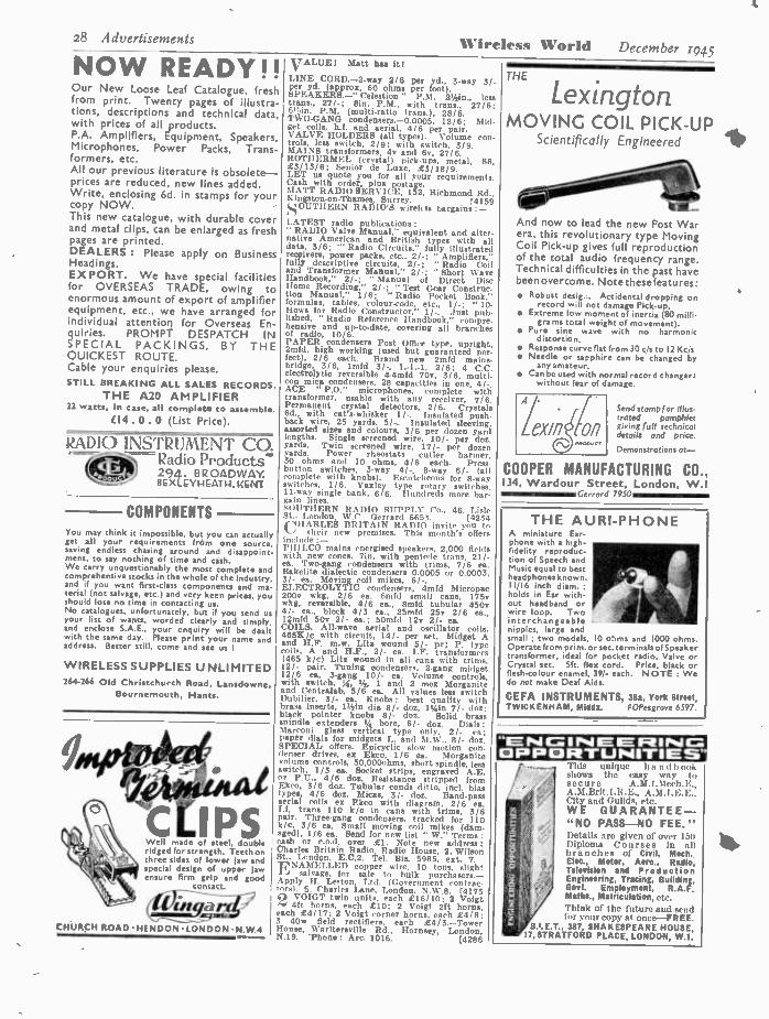
28 Advertisements Wireless World NOW READY!! Our New Loose Leaf Catalogue, fresh from print. Twenty pages of illustra- tions, descriptions and technical data, with prices of all products. P.A. Amplifiers, Equipment, Speakers, Microphones, Power Packs, Trans- formers, etc. All our previous literature is obsolete - prices are reduced, new lines added. Write, enclosing 6d. in stamps for your copy NOW. This new catalogue, with durable cover and metal clips, can be enlarged as fresh pages are printed. DEALERS : Please apply on Business Headings. EXPORT. We have special facilities for OVERSEAS TRADE, owing to enormous amount of export of amplifier equipment, etc., we have arranged for individual attention for Overseas En- quiries. PROMPT DESPATCH IN SPECIAL PACKINGS, BY THE QUICKEST ROUTE. Cable your enquiries please. STILL BREAKING ALL SALES RECORDS.
THE A20 AMPLIFIER 22 watts, in case, all complet to assemble.
C14.0.0 (List Price).
RADIO INSTRUMENT CO ` Radio Products" 294. BROADWAY. BEXLEYl- IEATH,KENT
COMPONENTS You may think it impossible, but you can actually get all your requirements from one source, saving endless chasing around and disappoint- ment, to say nothing of time and cash. We carry unquestionably the most complete and comprehensive stocks in the whole of the Industry, and if you want first -class components and ma- terial (not salvage, etc.) and very keen prices, you should lose no time in contacting us. No catalogues, unfortunately, but if you send as your list of wants, worded clearly and simply, and enclose S.A.E., your enquiry will be dealt with the same day. Please print your name and address. Better still, come and see us !
WIRELESS SUPPLIES UNLIMITED 264 -266 Old Christchurch Road, Lansdowne,
Bournemouth, Hants.
cLi Well made of steel, double ridged for strength. Teeth on three sides of lower jaw and special design of upper jaw ensure firm grip and good
contact.
CHURCH ROAD HENDON LONDON N.W 4
VALUE( Matt has it! LINE CORD. -2 -way 2/6 per yd., 3 -way 3/- per yd. (approx. 60 ohms per foot). SPEAKERS. -" Celestion " P.M. 21/2in., less trans., 27/ -; gin. P.M., with trans., 27/6: 61_in. P.M. (multi -ratio trans.), 28/6. TWO -GANG condensers. -0.0005, 12/6; Mid. get coils, b.f, and aerial, 4/6 per pair. VALVE HOLDERS (all types). Volume con- trols, less switch, 2/9; with switch, 3/9. MAINS transformers, 4v and 6v, 27/6. ROTIIERMEL (crystal) pick -ups, metal, S8, £3/13/6; Senior de Luxe, £3 /18/9. LET us quote you for all your requirements. Cash with lus postage. MATT RADIO SERVICE, 152, Richmond Rtl., Kingston -on- Thames Surrey. (4159 SOUTHERN RADIO'S wirelrss bargains:- LATEST radio publications :
RADIO Valve Manual," equivalent and alter- native American and British types with all data, 3/6; "' Radio Circuits," fully illustrated receivers, power packs, etc., 2/ -; " Amplifiers," fully descriptive circuits, 2/ -; " Radio Coil and Transformer Manual," 2/ -; "Short, Wave handbook," 2/ -; " Manual of Direct Disc Home Recording," 2/ -; " Test Gear Construc- tion Manual," 1/6; Radio Pocket Book," formulas, tables, colour-code, etc., 1 / -; "10- How's for Radio Constructor," 1 / -. ,lust pub- lished, " Radio Reference Handbook," cmpre . hensive and up -to -date, covering all branche' of radio, 10/6. PAPER condensers Post Office type, upright, 2mfd, high working (used but guaranteed per- fect), 2/6 each. Brand new 2mfd mains - bridge, 3/6, bud 3/ -, 1. -1, -1, 2/6; 4 C.P. electrolytic reversible 4 -4mfd 70v, 3/6, multi. con mica condensers, 28 capacities in one, 4/.. ACE ' P.O." microphones, complete with transformer, usable with any receiver, 7/6. Permanent crystal detectors, 2/6. Crystals 6d., with cat's -whisker II -. Insulated push back wire, 25 yards, 5/ -. Insulated sleeving. assorted sizes and colours, 3/6 per dozen yard lengths. Single screened wire, 10 /- per doz. yards. Twin screened wire, 17/- per dozen yards. Power rheostats cutler harmer, 30 ohms and 10 ohms, 4/6 each. Press button switches, 3 -way 4/ -, 8 -way 6/- (all complete with knobs). Escutcheons for 8 -way switches, 1 /6. Yaxley type rotary swilohes. 11 -way single bank, 6 /6. Hundreds more bar- gain lines. SOUTHERN RADIO SUPPLY Co., 46. sle St.. London, W.C. Gerrard 6653. (4234
li CHARLES BRITAIN RADIO invite you to
their new premises. This month's offers include :- I'HILCO mains energised speakers, 2,000 fields with new cones, 7in, with pentode trans. 21 /- ea. Two -gang condensers with trims, 7i6 ea. Bakelite dialectic condensers 0.0005 or 0.0003, 3/- ca. Moving coil mikes, 6/ -. ELECTROLYTIC condensers, 4mfd rdicropac 200v wkg, 2/6 ea. 6mfd small cans, 175v wkg, reversible, 4/6 ea., 8mfd tubular 450v 41- ea., block 4/3 ea., 25mfd 25v 2/6 ea., l?mfd 50v 2/- ea.; SOmfd 12v 2/- ea. COILS. All -wave aerial and oscillator coils. 465K/c with circuit, 14 /- per set. Midget A and II.F. m.w. Litz wound 5/- pr; P. type coils, A and H,F., 2/- ea. I.F. transformers 1465 k /c) Litz wound in ali cans with trims, 12/. pair. Tuning condensers, 2 -gang midget 12/6 ea, 3 -gang 10/- ea. Volume controls, with switch, 34, 5, , 1 and 2 meg Morganite and Centralab, 5/6 ea. All values less switch Dubilier, 3/- ea. Knobs : best quality with brass inserts, I1 /zin dia 8/. doz, 114in 7/. doz; black pointer knobs 8/- doz. Solid brass spindle extenders 14 bore, 6/- doz. Dials: Marconi glass vertical type only, 2/- ea; paper dials for midgets L. and M.W.. 8/- doz. SPECIAL offers. Epicyclic slow motion con-
, denser drives, ex Ekco, 1/6 ea. Morganite volume controls, 50,000obms, short spindle, less switch. I/3 ea. Socket strips, engraved A.E. tar P.U., 4/6 doz. Resistance stripped from Ekco, 3/6 doz. Tubular conds ditto, incl. bias types, 4/6 doz. Micas, 3/- doz. Band -pass aerial coils ex Ekco with diagram, 2/6 ea. I.f. trans 110 k/c in cans with trims, 3/6 pair. Three -gang condensers, tracked for 110 k /c, 3/6 ea. Small moving coil mikes (dam- aged), 1/6 ea. Send for new list " W." Terms : cash or c.o.d. over £1. Note new address: Challis; Britain Radio, Radio House, 2. Wilson St.. London, E.C.2. Tel. Bis. 5985, ext. 7. ENAMELLED copper wire, 10 tons, slight
salvage, for sale to bulk purchasers.- Apply H. Lesion, Ltd. (Government contrac- tors). 5. Charles Lane, London. N.W.8. [4175 cAd VOIGT twin units, each £16/10; 2 Voigt
4ft horns, each £10; 2 Voigt 2ft horns, each £4/17; 2 Voigt corner horns, each £418; 3 40w field rectifiers, each £4/3. -Tower House, 1Varltersville Rd., Hornsey, London, N.19. 'Phone : Arc. 1016. [4286
December 1945
THE
Lexington MOVING COIL PICK -UP
Scientifically Engineered
And now to lead the new Post War era, this revolutionary type Moving Coil Pick -up gives full reproduction of the total audio frequency range. Technical difficulties in the past have been overcome. Note these features:
Robust desig . Accidental dropping on record will not damage Pick -up.
Extreme low momenta( inertia (80 milli- grams total weight of movement).
Pure sine wave with no harmonic d istortio n.
Response curve flat from 30 c s to 12 Kc s Needle or sapphire can be changed by
any amateur. Can be used with normal record changer:
without fear of damage.
Send stamp for Illus- trated pamphlet giving full technical details and price.
Demonstrations ot-
COOPER MANUFACTURING CO., 134, Wardour Street, London, W.I sasmiiGrrrord 7930
THE AURI -PHONE A miniature Ear- phone with a high- fidelity reproduc- tion of Speech and Music equal to best headphones known. 1116 inch diam.; holds in Ear with- out headband or wire loop. Two interchangeable nipples, large and small : two models, 10 ohms and 1000 ohms. Operate from prim. or sec. terminals of Speaker transformer, ideal for pocket radio, Valve or Crystal sec. Sft. flex cord. Price, black or flesh -colour enamel, 39,- each. NOTE : We do not make Deaf Aids.
CEFA INSTRUMENTS, 385, York street, TWICKENHAM, Middx. FOPesgrove 6597.
"ENGINEERING OPPORTUNITIES' This unique ha nd book shows the easy way to secure A,M.I,Mech.E.. A.M.Brit.I,R.E., A.M.I.E.E.. City and Guilds, etc. WE GUARANTEE- " NO PASS -NO FEE." Detail, arc given of over i:di Diploma Courses In all branches of Civil, Mech. Elec., Motor, Aero., Radio, Television and Production Engineering, Tracing, Building Govt. Employment, R.A.F. Maths., Matriculation, etc, 'think of the futuro and send l'or your copy at once -FREE,
387, SHAKESPEARE HOUSE, 17, STRATFORD PLACE, LONDON, W.I.
L

December 1945 Wireless World Advertisements 29 AMATEUR WIRELESS SUPPLIES offer the
following equipment :- MAINS transformers : 250v 80MA, 5v 3A, 6.3v M, 25/ -; 350v 150 MA, 6.3v 4A, Sv 3A. 35/ -; 500v 200MA, 6.3v 4A, 5v 3A, 60/ -; 1,000v 250MÁ 75/ -; 6.3v 5A 19/6; 5v 3A. 15/6; or to order. Chokes : 2011 80MA. 16/ -; 2011 1,000MA, 20/ -; 1011 200MA,-24/6;
tor10H 250MA, 27/6; swinging choke, 5/15I1 250MA. 33/6; valves, rectifiers, 6L6, 6V6, etc. W / W Quality output transformer (multi - ratio), 35/ -; 0.0005 2 -gang, 12/ -; 3-gang, 14/6; electrolytics, 450v, 8mfd., 3/9; 16míá, 4/ -; switches, 4 -pole, 5 -way, complete with selector, unselected points shorted, 6/6 send 3.a. envelope for list. -16, Crystal Palace Parade. London, 8.E.19. [4431 CtUPREME RADIO, 746b, Romford 1,0 Manor Park, London E.12. Est. 15 years. Tel. I1t, 1260. MIDGET 2 -gang cond. trimmers, split vanes fixing bkte., 11/6; Midget coils A.H.F.T.R.F. high gain circuit, 8/ -; M.L. with circuit, 10/6 M.L. s.w,s.. 2/3; all -wave dials, 31,/inx4, 1/9 speakers, 31/2in, with tran., 29/ -; lase tran, 24/ -; 6in 26/6, less tran. 21/6; Bin 25/6. less tran. 20/ -; Celestion or Magnavox loin R.A. with tran. 32/6.. leis tran. 27/6; R.21.M.C.E., 8in, 2,000f1 pot, 31/6; mains trans.. Marconi, 4v, 350 +350, 31/6; other makes. 21/6. Midget chokes 60mile., 6/ -; heavy duty, 100-mils., 10 / -; P.P.'trans.. 6/6; droppers, 0.2a.. 110011, 2 sliders, fixing feet, 3/9: 0.03, 80011, 5/ -; Pye replacement, 3/3; 0.2 1.00011, 2 sliders, leas feet. 3/3; V /cs with aw. 4/ - less sw 3/9; all sizes wire wound 2,00011 to 10.00011, less ow. 2/6. Packets as- sorted resistances, coloured coded, wire wound, 200 -240,00011. 24in, pkt., 7/6; bias cond., 50- 50 3/6, 25-25 2/9; all Sizes resistances, 1 -watt type 8/- doz; 3 -way line cord, 60f1 ft. 2/- yd; tinned R.C. wire. 2/- doz yds; spindle couplings, 4/6 doz; pilot holders, 3/- doz; knobs, 14in spindle, 7/- doz; screen wire. single, 10d. yd., double 1/6; valve -holders all types, 9/- doz; midget valve caps, octual or standard, 8/- doz; solder, lib reel, 3/3; 22- gauge tinned wire, %etrlb reel, 2/ -; ow, cleaner, 2/- bot.; scratch remover polish, 2/ -; toggle e.w.e., single 2/3, double 2/9; P.B. wire. 11/2d yd.; H.T. panel strips, 1/- doz.; rubber steer- ing. 4d. yd.; many other lines; s.a.e. all en- quiries; no c.o.d.; 6d. extra orders under £5.
MAINS transformers, let grade, brand new, 4v or 6.3v type, 350/0/350 80ma, money
back guarantee, 20/- ea, post 1 /1.- Aneloy Radio, 36, Hindmans Rd., E. Dulwich, ß.E.22.
20watt amplifiers, 100 only. Government surplus, 6 Les in push pull, volume
and tone control, etc., low impedance output for p.m. speaker, finished in stove enamel. complete with valves, brand new, for ac only; E8 /15 c.w.o., packing nd carriage 5 / -. -Car- dings, 28, Dudley St., Wolverhampton. (4353 SURPLUS marine radio equipment for dis-
posal, receivers, transmitters W I'!' and R /T, motor generators, resistances, condensers. etc., at disposal prices.- Write, giving details of requirements, Box 4416. [4384 "LIMNS transformers, first grade, brand new,
350- 0 -350v 80ma, 4v 4a and 4v 2.5a or 6.3v 3a and 5v 2a, 20/- ea., post 1 / -; 8mfd 450v electrolytic!. 3/6; 200v. 2/3; 25 -25, 1/9; lmfd paper. 350v, 1 /9.- Aneloy Radio, 36, Hindmans Rd., E. Dulwich, 8.E.22. [4267
HENRY'S offer. -Philips wet electrolytic', small cans, 8mfd, 450V wkg, 8mfd 320v
wkg. midget, 25mfd 320v wkg, at 6/6; also 8x8 450v wkg, 6/9; (Mid 350v wkg, 2/3; 8mfd, 450v wkg, 4/ -; 16x16 block 350v wkg, 8/ -; amid, 200v wkg, 2/ -; amid, í,200v wkg, 7/6 T.R.F. m and 1 wave coils with reaction, 8/6 pr, with circuit; T.R.F. med wave midget coils, 6/6 pr, with circuit; 3 -bank 3 -way, 3- pole, with screen. 4/6; toggle switches. 2/ -. LINE- CORD. -0.3 3 -way 60ohms per lt. 3/- yd; 0.2 2way 115ohms per ft. 3/- yd. GOODMANS 3in P.M. 3 or 15ohme, 35/ -, with trans; 2 -gang 0.0005 midget condensers with trimmers and feet, 12/6; and 2 -gang 0:0005 ceramic ins with feet drum and drive spindle, 14/ -; 3 -gang 0.0005 ceramic ins, 12/6; Litz wire wound h.f. chokes. 2/ -; midget strong steel chassis size 9' / /x4ttlxll/2, with out -out for 5in speaker, holes for 5- valves and drilled for components, 4/6; s.a.e. for latest price tat, 4 -page. ENRY'S, 5. Harrow Rd., Edgware Rd., W.2.
41WPad. 2194. [4426 BRITISH MECHANICAL PRODUCTIONS,
Ltd., manufacturers of " Clix " radio com- ponents, announce that they are looking for- ward to an early resumption of business with the wholesale trade and are about to issue a statement of their sales policy and a revised list with prices (1945). The " Clix " range is much enlarged and improved. Will bona fide wholesale firms and others interested to receive this list plea.e communicate with O. A. Edgell, Sales Manager. 1, Church Rd., ,
Lsatherhead, Surrey. [4287
PREMIER RADIO (MORRIS AND CO. (RADIO) LTD.)
ALL POST ORDERS TO:
JUBILEE WORKS. 167, LOWER CLAPTON ROAD, LONDON. E.5. (Amherst 4723.,
CALLERS TO:
169, FLEET STREET, E.C.4. (Central 2839.
1945 LIST NOW AVAILABLE. KUNDREIS OF NEW LINES.
All engxiei,. moat be accompanied by a lid. stamp. BUPERHET TUNING KIT, comprising 9 midget coils for R.F._ Aerial and Oso. covering 16-47, 200.557 and 700 -2,000 m., suitable switch, all padders and trimmers, 88 /10. Worth double. Also available a sultable 3 -gang condenser with complete 8.M. drive and dial, 30; -. MIDGET MOVINO COIL UNITS. 1110. dlsm Highly sera +it Ive, may he need as mike or speaker. Complete with trans (state whether L.S. or Mike tram. required). 22(6. 10-WAY PUSH BUTTON SWITCHES. complete with knobs and escutcheon plate, six Iron coral cows. Trimmers and Padders. No circuit or other partivolars available. To clear at 12/6. Original ... 45' -. FIRST GRADE METERS. Mkt diameter, 1
muliamp. £2 12s. ; 600 mlcroamps £2 18.. 6d. elia. I milllamp, £3 5e. ; 600 microampe, fa 6d. Westinghouse Meter Rester for either type, 10/ -. Multiple ehupts, 10, 100. 500 mf!, 10 / -. Any value multiplier. 2/6 each. 12 -WATT A.C. AMPLIFIERS. 3 stages. High and low gain inputs. Mike pick -up mixing feed- back, yrovielon for 2, 3, 4, 8 and 15 ohms output, £14 14e. SUPER QUALITY AC/DC 15 W. AMPLIFIER. 3- stage, high gain, push -pull, in steel cabluct. £15 15s. AC/DC AMPLIFIERS, 5 watts output high gain three -stage, feedback. £8 8e. BATTERY CHARGERS for 2 v. bat.. at I a., 26/. ; for 2, 4 or 6 v.batt. atl a, 45/ -; for v.batt. at 1 a., 30,-; for 2, 6 or 12 v. bitt. at 1 a., 49,6 for 0 v. or 1.2 v. bait. at 4 a., M. MAÜ9 TRANSFORMERS, 300 +300 v.. 60 min, three 4 v. 2 -3 a. winding.. 25'- ; 350 + 350 100 15/. 6 v. 2 a.. 6.3 v., 2.3 a.,291_,- 350 + 350
lass 100 m /a. three 4 v. 2 -3 a wind, 29/ -; 360 +350 160 m /a., 4v. 2 -3 a, 4 v. 3.6 a., 4 v. 1.2 a., 4 v. 1.2a. wladluge, 381. ; 350 +360 160 m /a.. 6 v. 2 a., 6.3 v. 2 a. 8.3 v. 2 a., 86/.; 600+600 260 m /a.. 6 v. 3 a, 6.3 v. 2a, 6.3 v. 4 a, 66/. ; 425 +425 200 cola, 4 v. 2 -3 a., 4 v. 2.3 a, 4 v. 3-6 a., 47/ -: 350 + 850 150 m /a., 4 v. 1 -2 a., 4 v. 2 -8 a, 4 v 3 -4 a., 36/- ; 600 + 500 150 m /a. tour 4 v., 2.3 a LT winding., 47/ -. 1 -VALVE BATTERY S.W. RECEIVER, with 2 -volt valve, 4 cogs, 12 -170 m. bandepread tuning, 66/., including tax. CHASSIS, 10 o 8 x 2iln, 7/- ; 18 x 8in., 8/6 : 20 x die. 10/6 ; 12 x 9 x 24In., 7/9. SHORT -'WAVE Goan et octal socket. 4-pin aerial coils, 9.15, 12 -26, 22.47, 41.94, or 76 -170 r., 2/6 each ; 150 -360 or 255.660 m., 3/- : 490-1.000 or 1,000 -2,000 m. 4,-; 6-pin H.F. Tram., 9.16, 12.26, 22-47, 41 -94 or 76 -170 m. 2/6. e.W. chokes, 10-10Q m., 1/3 6 -200 m., 2/6. SHORT -WAVE CONDENSERS, easily ganged, 16 mmfd., 2 /11. 25 mmfd., 3;3, 40 =dd., 3 /3, loo mmid., 8/11. 100 mmid., 4/S. 260 mm/d., 5/8 abaft couplers, 6d.; flexible ditto, 1/.. Dust bandepread for use with 2 -gang, 6/6. =CRT w P " TYPE COILS, 12-35, 1647, 34.100, 91.261, 260.750, 700-2.000. 200-557, available a. H.F. trans., serial, or oec. colts, 2/3 each. Valley type wave -change awitebee, every type available; locator,. 2/6 each ; wafers, 1/6 each. Small 2 -gang condensers : 0.0005, 12/- : Matched pain Iron - cored 466 K.O. LF. tram., 15'- pair : midget I.F. tram. size 1í1o. x In. x ¡In., 41(5 Kies, adjustable Iron cores, 10/6 each; 60 mmfd. trim
rs, 1 - ; osc. padder, 600 mmfd., 1/9 ; R.F.O. 213
SMOOTHING CONDENSERS, 50 mf., 12 r., 213 ; 25 mt.. 25 v. 2/3 ; 50 mf., 60 v. 3/- ; 8 mf., 500 v., 3/. ; 16 ml., 160 v., 3/. ; 16 ml., 350 v., 313 ; 16 x 16 mf., 350 v., 8/6 ; 12 mf., 600 v., 4 6 ; 24 inf.. 500 v.. 616. AMERICAN VALVES, 26E6, 25E6, 6V8, 6F6, 5z4, 80, 6L7, 6K7. INS, 106. IH6, ITS. Many others available. SUPER GIANT PUSH -PULL INTER -VALVE TRANSFORMERS.. 21/ Midget type, 12'6. MOVING COIL SPEAKERS Rota bin., 21/6; .Fin.. 22/6 ; ela.. 24/.. Ooodroane 311o., Above are less output trans. Plessey 8 -in. P.M. with trans., 29/6. 8in. 2,000 ohm eoergieed speaker. 85/ -. Midget standard or P.P. trans. for any above, 10 /6. Super quality giant Matchmaker output transformers, match any tube single or P P to any voice coil. 7 -watt, 22/6 ;
15watt, 10'-; 30 -watt, 4916 ; 60-watt, 59/6. CHOKES 8H. 300 ohms, 10 m /a, 4/6 3of, 400 ohms. 60 m /a., 9/6: 00H, 100 m /a., 400 ohms, 15 /- ; 30t1. 106 ohms. 160 m /, 25/ -. 25H. 250 in s., 120 ohms, 39/6. SUNDRIES. 2 mm. eystollex. 21d. yd. ; rein -
cored solder 6d. per coil or 4/6 per lb. screened 2-pin plugs and socket, 94. ; ditto 8 -pia. 2/ -. Octal socket., 6d. ; ditto, amphenoi type, 1 / -. Valve screens 1/2. 6 -volt vibrators, 4 -pin, 12.6. 60ft. Indoor Aerial, 216. Volume Con- trols, any vales 11/9 ; with swlteh, 51/
VORTEXION transformers and chokes, etc.,
not supplied o"; wound t
B.B.C., n Pspecifiton 1ml tated but unequalled.-Vortexion, Ltd., 257- 261, The Broadway. Wimbledon, 8.W.19. Tel. Liberty 2814-6128. [4356 SERVICEMEN. -The following products are
well designed and of high quality; volume controle, carbon type, all values, with or leas switch, wire -wound resistors, 1 to 6owatts; dropper resistors, 0.2 and 0.3 amp; line cords and razor resistors; terms and quotations on req.- Dagole, Ltd., 5, Torrens St., London, E.C.1.
MOVING coil hand microphones, p.m., ener- gised by Alni magnets, 45 ohms. ' in
coil, fitted with switch in handle; 12/6 each. MOVING coil headphones, p.m., energised by Alni magnets, 45 ohms, 1/2in coil, ideal for mikes, miniature loudspeakers, etc., over- all ni bakelite cases with 3in front flange, 7/6 each, per pair with headband 16/6; throat microphones, fitted with elastic bands, 'phone. plug, etc., 7/6 each. SYNHRONOUS motors. Sanmamo, 200-250 volts ac, 50e, self- starting, fitted reduction gears, ideal movements for time switches, in- dustrial, dark room, electric clocks, etc., rotor speed 200 rpm, final speeds available: 1 rev 12 mina 22/6, 1 rev 30 mint 25/ -, 1 rev 60 mine 25/ -, consumption 21,4 watts, size 24ax2ysxlr /g ill; each with order; registered post and packing 1/- extra, PERMS: Cash with order. -H. Franks, Scien- tific Stores, 58, New Oxford St., W.C.1. Tel. Museum 9594. [3961
TELE -RADIO (19431, LW., for new cont- ponente at list prices. Precision sub-
standard condensers, 1X accuracy, 0.0001m1d 37/6, 0.001mfd 18 / -, 0.01mfd 21/, O.lmfd 271 9. lmfd 45/ -; wirewound precision resistors. Weston meter, 0 -250 micro amps, centre zero. £3/5; C.A. tubes; Keeton mains transformers. chokes and output transformers, instrument wave -change switches, 2-gang condensers with sm drive, 16/9 ea.; Vitavox and Celestion speakers specialists in short -wave work; new list ready shortly; send stamp. -Tele -Radio 119451, Ltd., 177, Edgware Rd., London. W.2. 'Phone : Pad. 6116. [4086
INSTRUMENT Wires.- Lewcos enam. copper wires, 14- 16.18- 20- 22- 24 -26- 30.34 -38.40 -43
owg, 2/9, 3/ -, 3/3, 3/6, 3/9, 4/ -, 4/3, 4/9, 5/3, 5/9. 6/ -, 7/- per lb.; less than lib reels 2d. extra, over 1 to 21b reel 4d. extra, over 2 to 81b. reels 2/6 extra. All reels returnable. Also doe enam. /sae Limes, etc., coverings. Many other interesting radio and electronic items. Lists Id., s.a.e. Orders over 30/- post tree. -Midland Instrument Co., 18, Harborne Park Rd., Birmingham. 17. (4347
BUY direct and save; complete kits- Vic - tory 4e ac/dc, £611916; L /MR; 7/6
extra; Victory 3v 8.G., battery, automatic bias, 25/19/6; LIMW 7/6 extra; B.M. dials, es- cutcheon glass, round, square. 7 /-; full vision
8 /6; M.T. 350 -0 -350 90ma 6v, 4v. shrouded, 23/6; 2 -gang Midget 8.11. trimmers, 14/6; line cord, 2 -way 1/6 yd, 3 way 2/ -; epk. cones. all 6/9' 1(í1b enam. wire, all 2/3; 8mfd. 150v, 2/ -; " coils, 2/3; 0.5 amp 2v chargers, 25/ -; chassis, 4/6; send for full lists. -Bue- clench Radio Manufacturers, 1 and 2, Melville Terr., Edinburgh. [4367 PUSH -PULL high fidelity output trans-
formers, shrouded, surface mounting. grey finish; O.P.1. P.X.4, lOwatt. tapped see. 3, 8. 15 ohms, 25/ -; O.P.2, 6F.6, lOwatt. tapped sec., 2 -5, 5 ohms, 25/ -; O.P.3. 6.L.6. 25watt, tapped sec., 3, 8, 15 ohms, 32/6: O.P.4, P.X.25. 25watt, tapped sec., 3, 8. 15 ohms, 32/6; choke for O.P.1 and 2, 120nia 2011 200 ohms, 25/ -; choke for O.P.3. 4, 200ma 20H 100 ohms. 30/ -; choke for 6.I..6, heavy duty, 1,000 ohms. 150ma, 35/ -; any type transformer made to specification; cash with order, postage 1/- each. -Boscombe Radio. 595 Christchurch Rd., Boscombe. (4239
THEHE Simplex Four, complete constructional Midget ac /dc receiver (total cost
of construction £91. theoretical and full -scale layout diagrams, with instructions, per copy. 416; midget cabinets, in red or brown, 25! -; Midget m wave t,r.f. coils. high gain, 7/6 pair ; the latest, iron cored m and I wave, t.r.f. coils, adjustable cores, with circuit, 12/6 pair; ditto a and ose coils. m and I wave, for pocket receivers, LI. at 465 kcs with circuit, 17/6 pair; a and ose coils, s.m.l. wave, do i.f., with circuit, 15/- pair; midget i.t. trans- formers, 465 kcs, 15/- pair; midget speaker trans. 4/6; midget chokes, 6/ -; standard chokes, Soma, 8/ -; heavy, 150ma, 12/6; chassis, drilled 5 vales, 91/2x41 /x1i,_in, 4/6; 4 valves. 11v416x2in, 7/6: midget 2 -gang 0.0005mfd variable condensers, 13/6; midget s.m.I. wave ,dial. 4x31/2in, 2/6; etc., etc., monthly com- prehensive lists, 2íd. stamp with enquiries. postage all orders.-0. Greenliok, 34. Bancroft ltd., CambridgeeHeath Rd., London, E.1. Ste. 1334. [4413

30 Advertisements Wireless World December 1945
SEXTON'S of 138, Gray's Inn Rd., London, W.C.I
for SALES, SERVICE & SATISFACTION Electric Smoothing Irons. Weight, 5 lbs., for AC /DC Mains, 200/220 or 230/250 Volts. Strong Bake- lite handle and thumb button. Fitted with Heavy Connector guard and back rest. Base specially designed for ironing under pleats, seams and buttons. Complete with two yards of best quality three -core flex and earthed connector. Beautifullyffnished in nickel and coloured pastel shades. Blue, Red, Green and Gold. Approved price of 33/4 each, includ- ing purchase tax. Post paid. American Radio Valves .-Types as under at controlled prices. 45Z5GT, SY3G, IA5GT, IC5GT, IQ5GT, ITSGT, 3Q5GT, 80G at I I - each. 6JSGT, 12J5GT, IHSGT, 12SF5GT, at 9 2 each. 6Q7GT, I2Q7GT, 12SQ7GT, 75G, at 1117 each. 12SJ7GT, 12SK7GT, 6J7GT, 6K7GT, 6K6GT, 6V6G, 25L6GT, 42G. 43G, 50L6GT at 12/10 each. 6Á7G, 6ASGT, 6K8GT, at 14/. each. 6C6G, 6D6G, 11 - each. Postage paid.
LOUDSPEAKERS " Goodman's " 31in. with 2/3 ohms voice coil. 30 - each. " Rola," Sin., less transformer, 21'6 each. " Celestion." with transformer, size 8in., 27/6 each. " Mag- navox " with multiratio trans. size 8in., 30 - each, all the types as given are Per- manent Magnet. " Celestion," size 10in., Mains energised with 2.000 ohms field, less trans. 35 - each. Post paid. Terms : -CASH WITH ORDER ONLY. We regret that we are unable to send goods C.O.D.
Telephone ; TERMINUS 1304 and 4842.
THE BEST BOOKS WIRELESS TERMS EXPLAINED By " Decibel." An invaluable guide to the technical terms used in wireless. It explains the meaning of every term in the fullest and cl manner, with numerous illustrations. Second Edition. 3s. net.
WIRELESS TELEGRAPHY: Notes for Students
Compiled by W. E. Crook, A.M.1.E.E., etc. This book represents the theoretical part of the Wireless Course given in England's Air Training Centre, and sets forth in simple language, with no more than the necessary minimum of formulae and mathematics, all that the candidates need know in order to satisfy the examiners of the adequacy of their knowledge. Third edition, 7s. 6d. net.
ELEMENTARY HANDBOOK FOR WIRELESS OPERATORS By W. E. Crook. An up -to -date book presenting a general view of radio communication with an introduction to its technique. It gives all the information necessary for a complete understand- ing of the subject in a clear and easily under- standable manner, with profuse diagrams. Second Edition. 4s. net.
D/F HANDBOOK FOR WIRELESS OPERATORS
By W. E. Crook. Gives a very clear explanation of the principles and theory of direction finding apparatus, together with an outline of general D F practice. Second Edition, 3s. 6d. net.
PITMAN P1srAE HO17dL PAU= iREEEfl, ]gaOdwAR, w.O.G
GA. RYALL, 65. Nightingale Lane, Clap - ham, 8.W.12. -Mail order only no c.o.d.
under £1 please; postage extra orders under 10 /
VOLUME controls with switch, long spindle. new, Morganite, 442meg. guaranteed. 41.; ditto %meg, leas switch, short spindle. 2/3; 1meg. extra long spindle, 2/6; 10.000 ohm, less switch, 2/6; twin screened microphone cable, Aerialite, 3yds 2/6 Hunts 0.01 mica. 1/- each; aluminium coil cans, robust, 2rsin high. 2t18 across base, 2 for 1/3; Octal 8 -pin plugs, with insulated metal caps. complete with In- ternational chassis type bases, 3 for 2/6, or 8/- dozen; with solder tags. 3 for 3/ -, or 10/- dozen; miniature 4 -pin plugs, robust pins, complete with metal caps and sockets, 3 for 1/6. 4/6 dozen, 29/- 100; condensers, 0.1 tubular, 350x. 7/6 dozen; 450e wkg. pairs mtd. on pax. strip, 8/6 per six pairs; cable. 10 -way, with five 5 -amp low tension conduc- tors, 4/- yard; push -back stranded connecting wire, 12yd coil 1 /6, or 12 coils 12/9. ERIE t,,watt resistances. 330. 450. 10,000, 22.000, 33,000, 220.000. 470.000. 2meg, insu- lated type except 33,000. 3/9 per dozen; Erie 2watt resistances. 680, 6.800. 140,000, 150.000. 220,000, 470,000, 820,000. 2 for 1 / -, 5/- per dozen; Morganite resistances. carbon, 500. 1.000, 50,000, 2meg, 3/6 dozen; Erie 680. 3watt. 1/3 each; T.C.C. mica condensers. 0.0001x0.0001, bakelite cased, five (ten con- densers) for 1/3, or 12/6 per 100; valve holders. chassis types, British 5 and 7 -pin. American UX, 4, 5, 6 -pin and international Octal, all 41- dozen or 29/- 100; set 5 Cyldon ceramic trimmers, 30mm, on metal base, 1/6 each, per dozen 12/ -. MANSBRIDGE 4m1 high quality baseboard mtg condensers. with terminals. T.M.C., 4/- each, 3 for 10 / -; 250y wkg; Celestion 10 -inch permanent magnet speakers with pentode transformers, high flux magnet of great power, 30 /- each; meter switches. 11 -way, long spindles, take lin behind panel, 4/9 each. 3
for 12/ -: Yaxley type switches. 3 -bank, 2 -pole. 4 -way. with middle screen, long spindle. 4
shorting bers, 4/9 each; Yaxley type switches. single pole, double throw, 2 -bank 2/9; single bank 2/3; input strips. 2 -way, with terminal screws, 2inx3/4in, 2/6 dozen; anchor or mtg. trips for resistances, 2/6 dozen. --O, A. Ryall.
METAL rectifiers, charger kits, pick -ups, condensers, metal rectifier 12v 1.5a type,
with transformer and ballast bulb for 2e to 12v charger, no rheostat and ammeter needed. with circuit, 37/6, postage 10d.; ditto with 12v 2.5a rectifier, 46/6, post 10d.; metal rec- tifier, 2 ',2amp, with transformer, makes ideal trickle charger for 2e cell, 13/6, post 7d.; metal rectifier, well -known make with circuit, 12e 4amp. 32/6; 12e 1.5e, 10 /6r, postage 7d.; Junior 12v lamp rectifier, 7/6, post 4d.; 12e 2amp, 16/6; 2.5amp, 18/6; 3amp, 27/ -; M.B.S.1. instrument rectifiers, 18/6; charger kit for 6e car battery at 2amp, 37/6, post 10d. METAL rectifiers all types stock. for conversion of valve type chargers to metal rectification. HEAVY duty charger kits, weight 151b, trans- former and rectifier for 6v -12e 4amp, £4; 6v- 12e 5amp, R4/10. post 1 /1; transformer. metal rectifier and ballast bulb for 3-cell to 20 -cell at lamp charger, guaranteed one year, £5/10; charges up to 20 cells at full lamp. also trenafnrmer, rectifier and ballast bulb for 6v- 12v 3amp charger, ideal or car battery, 59/6, pont 1 /1; Hunts 8mfds 450e surge proof ubu- lar electrolytics. 3/8. past 3d.; Rothermel senior bakelite pick -ups. 75/9. MIRES. -Rothermel Bullet " crystal micro- phones. black finish, £3; D.104 mike, plated housing. £4/4; Rothermel D.106 miniature deaf aid mike, £2/2; moving coil mikes and stands in stock. CHAMPION. 43, Uplands Way, London, N.21. Tel. Lab. 4457. (4425
SERVICEMEN'S parcels, inclg. 2 gross 4 &
6 B.A. screws & nuts, 24 Igths. syato-flex. 3 0.1 tubulars. 6 tow resistors, 10/6. post free. -Radio. 110, Weçllingboro Rd., Northampton.
DRY cell. -Old -established battery firm now in production of all types of dry cells;
D.R.3 speciality; delivery ex works; quotations by request; contracts invited. -The Ablest Bat- tery Co., 117. Anerlev Rd., Anerley, 8.E.20.
AVO oscillator, £13; Paul Unipivot micro ammeter. £4/10; Morse inter. with tape,
£6/10; Weston 0.10, ma, £115; Weston 0 -50, ma, £115; T.C.C. 4 +4 1,700v. wkg, £2/10: parts for wire recorder (television and saw. world), including recording head and r,4Ih steel wire. £2/10; 500v alternators; these excellent little machines work well as s. do generator, giving 12v 3a self aligning roller bearings, laminated fields and armature. £1 /5; Savage 1,000- 0.1.000v 250 ma. £4/10: rectifier heater trans for above, £1 /10; T.C.C. 0.5mfd, uncased, 1,700. wkg, 3/- ea; Ultra car radio, needs one new valve and attention, £4110; polarised relay. operates on 0.5 ma £1/5; C.E.C. 3ln C.R. tube, £2 /10. new. - 0.5JV, 198, Harrow View, Harrow, Middx.
ARMSTRONG THE FUTURE
The active war is over. Gradually restrictions are being removed. Now we can get down to preparing plans for our NEW ARMSTRONG CHASSIS.
ARMSTRONG QUALITY is well known. Our new chassis will make it even better known.
ARMSTRONG TELEVI ON CO. LTD. WARLTERS ROAD, HOLLOWAY, LONDON, N.7
'Phone: NORth 3213
\ I 11 WESTMORELAND RD.,N.W.e - COUNDALE 7131
W. BRYAN SAVAGE LTD.
Expert assistance in the solution of problems relating to
e TRANSFORMERS, CHOKES *AMPLIFIERS POWER UNITS
and Specialised Equipment embodying
ELECTRONIC CONTROL l at VIBRO -ARC" Engraving Pen
Post
Peet
For rapid engraving any metal -hard or soft.
Operates from 4 -6v. Battery or A.0 . Trans- former giving 6-10 amps.
HOLBOROW, 46, Boroughbridge, Yorks.
POST -WAR TELEVISION The advance In Radio Technique open unlimited opportunities of high pay and eec,ve poste fur those Radio Engineers who have had the foresight to become technically qualified. How you can do this quickly and easily in your spare time is hilly explained In our unique haudhoot.
Full details are given ,e A.fd.LE.E., A.H.Brü.LE.E. City & Guilds Esama., and particulars of up -to -date course.. in Wireless Esxiaeerisg, Radio Servicing, Short Waves, Television, Mathematics, etc., etc,.
We Guarantee "NO PASS -NO FEE" Prepare for to-morrow's opportunities end pod -awe competition by sending for your copy of this very Informative 112.page guide NOW -FREE. BRITISH INSTITUTE OF ENGINEERING
TECHNOLOGY (Dept. 38$) I7, Stratford Pleas, London, W.1

December 194.5 Wireless A really good
trüaatifOraaaere>-
iVorid
Areally good transformer calls for equally good mounting methods. The illustration shows a skeleton framework as used on all A.E.E. Air -cooled transformers, rated from 5 VA. to 5 KVA. These are NOT just crude pieces of bent strip or brittle castings, but scientifically designed interlocking
pressed steel sections. This construction ensures :- I. Absolute Rigidity. 2. No lamination buzz or vibration. 3. Fixing centres pre -determined and
maintained to hairbreadth accuracy. 4. Winding Axis horizontal or vertical,
as required. Our other products include " Interlock "Transformer Bobbins, Power Supply Units, Audio Amplifiers. Electronic Test Equipment.
ASSOC IATED ELECTRONIC ENGINEERS LTD.
DALSTON GARDENS, STANMORE, MIDDLESEX. Wordsworth 4474/5/6
SOLON Industrial Type Electric Soldering Irons rated at 65 watts are now available for use where a low voltage system of supply is employed. There are two models, one fitted with an oval tapered bit as illus- trated, the other with a
round pencil bit, and they will do the same class of work as the well -known SOLONS of 65 watt rating for normal supply voltages.
W. T.
Their design in-
corporates the many
specialSOLON features.includ-
ing the fitting of the heating ele-
ment inside the bit. Both models can be
supplied fitted with elements for 12 volts or
for 24 volts supply, as required. Complete with
6 feet of HENLEY twin core flexible. Write for
details of the complete SOLON range of law and normal voltages.
sOLON SOLDERING IRON ..INGUST51A1 JSE
HENLEY'S TELEGRAPH COMPANY, LIMITED,
Engineering Dept., 51'68 Hatton Garden, Leaden, 11.0.1
WORKS
B.A. thread screws, gross useful sizes, 2/6; ditto, nuts, 2/6 gr.; assorted gross screws
and nuts, 2/6 gr.; ditto, brass washers 1/6 gr.; fibre washers, 1/6 gr.; assorted soldering tags, 2/- gr.; assorted small eyelets and rivets, 113 gr. Large stock of screws} etc.; state wants. Rubber -covered stranded copper wire, ld. yard; heavier quality, i .il. yd.; very heavy quality, 21/2d. yd. 'Pinner copper con netting wire, 201t coil, 6d.; ditto, rubber - covered, loft, 6d.; finest quality stranded push - back wire, 12yds, 2/3; twin bell wire, 12yds, 1/9; ditto, heavier quality, 12yds, 2/3; ditto. flat rubber covered, 3d. yd. Woods metal stick, 21/zin by %in, 1 / -. Cotton -covered cop- per instrument wire, %Ib. reels. 16, 20. 22. 24g., 1 /6; 26, 28g. 1/9; 30, 32g., 2/ -; 34g., 2/3. Enamelled ditto, same prices. Also 36g., 2/3; 38, 40g., 2/6. Silk- covered ditto, 2oz. reels, 24, 26, 28g., 1/6; 30, 32, 34, 36g., 1/9; 42g., 2/ -; 16g., D.S.C., 11b.. 5/ -; all post extra; s.a.e. with enquiries-Post Radio Supplies, 33, Bourne Gardens, London, E.4.
COULPHONE RADIO, Station Rd., New Longton, Nr. Preston. -Return of port
mail order service; new goods only; c.o.d. or cash with order; all orders over 5/- post free. higheet quality goods at unbeatable prices; all Tuagaram and B.V.A. valves; mains trans- formers, 200 -250v primaries; 300- 0 -300v 60ns.A 4 or 6.3v. L.T.s, 17/6; 350-0 -350v 100m4 4 or 6.3v L.T.s, 24/ -; 425- 0-425v, 200mA, 4v 8a, 4v 4a, 4v 4a, or 6.3v 4a, 6.3v 4a, 5v 3a, 47/6; 350v 100mA bobbins, 15/6; chokes, 60mA 7/6, 100mA 15/ -, 200mA 21/ -; P.M. speakers, le -s trans[., 21; tin 24/ -, 31.in 27/6, Sin 19/6, 61,:ín 20/ -, 8in 21/ -, 10in 30/ -; with Pentode transt., 61,gin 24/ -, 8in 25/ -; energised speakers with Pen. transi., 1,200 or 2,000 field, 30/ -; Vita - vox 12in Super K12 / /10, £7; speaker field coils. 1,000, 1,500, 2,000 or 2,500 ohms, 6/6; speaker transformers, push -pull universal types. 4watt 6/6. 8w 10/6, 15w 21/-, 30w 37/6; Midget Pentode, 4/6; mains dropper resistors, feet, 2 sliders, 800f1 0.3amp, 4/6; iron -cored Li. transi.. 465kc/s, 13/6 pr.; Rothermel Senior Xtal pick -ups, 78/9; push back wire, 2d. yd 50ít 2/6, 100ft 4/6; tinned copper wire, 2/- reel . Systoflex 2mm, 2d. yd.; resin -cored so der, 4/. lb; 414ín B.S. 1st grade milliammeters, 0 -1mA, 70/ -; midget 2- gangs, 0.0005, with trimmers and feet 11 /6, 3 gangs 13/6; electrolytics, 8x450 4/6, Bx 8x450 7/6, 2x350 3/ -, 25x25, 50x12 2/ -, 25x50 2/6, 50x50 2/9; line cord, 0.3 amp. 60(1 per it., 2 -way 1/6 yard, 3 -way 1/9 yard; carbon resistors, %w 6d., 1w 9d. 2 W.B. TRF. coils, with reaction, 12/6 pr; 3W.B. euperhet. coils, 465kc /s, 13/6 pr; valve -holders, all types, 6d.; Dubilier Centralab. vol. controls, less switch 3'6, with raw. 4/9; Pyrobit instru- ment soldering irons, 21/ -; 3 -way cable, 6d. yd., 5w. lad. yd; trimmers, 50pí. 9d., 500pí. 1/9; Vortexion and Brierley amplifiers. Send s.a.e. for comprehensive list. [4330
NEW LOUDSPEAKERS 0 BAKERS 18in P.M. L.S., list £8/1916, Al unused, £15 pair. -J. Worden, Lightfoot Lane Broughton, Preston, Lanes.
áG+
[4289 S /18/6. -New Baker Super Quality 12í1
Auditorium permanent magnet speaker with triple cone manufactured by Bakers Selhurat Radio, the pioneer manufacturers of moving coil speakers since 1925, wide Ire - quency range, even response. ideal for quality reproduction, fitted with magnet, having ex- ceptionally high flux density in the air gap. suitable for Public address equipment when quality reproduction is first consideration; send 21/2d stamp for leaflet giving details of above and constructional details of a new acoustic chamber designed to extend loud speaker frequency range. £8/19/6. -New Baker super power cinema per- manent magnet speaker with 18ín triple cone of new design, giving wide frequency response free from objectionable resonances; speech is clear and natural and music is reproduced with exceptional realism; fine engineering job. extremely sensitive; ideal for public address equipment when power handling capacity, plus realistic reproduction, is required; prompt delivery per pass. train. -Bakers Selhurst Radio, 75, Sussex Rd.. S. Croydon (Croydon 6813).
LOUDSPEAKERS, SECOND -HAND 17-MGT light coil twin with H/C horn, £25;
would separate. -Box 4089. [4301
EPOCH Domino, new condition, £6. -107,
Tower Ilill, Birmingham, 22A. (4371
VOIGT unit and large horn; offers. -Cooper, 45, Muswell Rd. Lqndon, N.10. [4378
MAGNAVOX " 66 t' with power supply. 230v
AC, beautiful tone; offers. -Box 4159.
BAKER 12in triple cone speaker, new, Ills- used, surplus to requirements, £4/10.-
Box 3986. [4291
BAKERS 12in 1611, 1250f) field, .£3
N.M.V. heavy 10in, 1514. 1.5000 field, as new, 70/ -. Rola, R.K., etc., some need re- pair, 6/- to 50/..-J. Worden, Lightfoot Lane, Broughton, Preston, Lancs. [4290
Advertisements 31 - ELECTRADIX ROTACEPTORS. Pre -war type for E.H.T. at 50 cycles from 12 volts D.C. two sizes 5,000 volts and 10,000 volts at 20 m.a. for portable neon luminous tubes or daylight colour matching lamps. Completely ironclad with small interruptor motor at top, transformers and condensers below. Overall size 6" x 4E' r 131" high, t.6 10s. each.
ROTARY CONVERTERS. New D.C. /A.C, 110 220 volts 100 watts, 112 ; 110'110 volt 100 watts, LIO. All with smoothing units. L.T. DYNAMOS. We are again able to offer a few Charging Dynamos 6, 12, 24 or 32 volts, 120'150 watts, circular body, car type. Send us your enquiries. MOTOR BLOWERS. In addition to mains A.C. /D.C. Blowers we have some for low voltage D.C. 32 volt O h.p. with output of 500 cub. ft. per minute, L8 IOs. ; also some small valve cooling or Lab. Blowers work off 12 volts, LS 10s. We have other Blowers in stock up to 6 h.p.
FANS. Table model Fans, A.C. 220 ;230 volts, with 10" blade and guard. 4Ss. nett. TRANSFORMERS. We have a number of } kW. Transformers, shrouded, with several taps, output unmarked, unused Government Surplus,
; 3 W. Carcases with laminations and wire, damaged by blitz. 4S ;- each. CONTACTORS. Auto Cutouts and Solenoids in all voltages from 24 volts and current to 500 amps. ROTARY SWITCHES. " On -off," 10, 15 and 40 amps., 7 6, 10 - and 12,6 each.
FILTERS. 30 volt A- C. /D.C. Filters in metal box. 12 6. MICROPHONES. Studio and Announcers' Mikes, hand or stand, Tannoy multi -cell carbon mikes in case and mounted on chrome table stand, 75, -, or on extending floor stand, 80'- ; Trans- former, I0'- extra. Tannoy Hand Mike with switch in handle, 211 -. Lesdix No. Ila Hand Mike, carbon inset in solid brass case, the sensi- tive diaphragm protected by a perforated metal panel. 8 6. Detectaphone Mike Buttons, 2;'6. Transformer, 4/6. BELLS. Outdoor Ironclad, Tangent, for works or schools, 230 volts A.C., 42/ -. Indoor House Bells, 5'9. Bell Transformer, 3 -5-8 volts, 7/6. BATTERY CHARGERS. Lesdix " NITNDAY " Chargers. metal rectification, 2 volts } amp., for wireless cells to large chargers for your car accumulator. Send for special Charger leaflet. METERS. D C. Moving -coil milli- ammeters, 0 -1 ma., 100 ohms resistance, 24' flush panel. bakelite case, 55,' -. Instrument Rectifier, 10,6. Few large ironclad Switchboard Meters. Send us your enquiries. PETROL ELECTRIC PLANTS. 500 -watt direct coupled Stuart, 50 volt D.C., £45. Stuart Turner 12 volt D.C. Motor Pumps, 120 g.p.h.,
SWITCHES. 8 -way Lucas switch -box ex- R.A.F., 3/6 ; 6 -way, 3' -. G.P.O. Lab. Switches D.P. reversing, for model control motors, etc., 7/6. 10 amp. D.P.D.T. Rotary, 2;6 each. MAGNETS. The wonder midget Magnet, alni perm. steel disc, weight only I oz., I" dia., I- thick with 3,16- centre hole, 3 6 each. Large selection of horseshoe Magnets in stock. Send for leaflet ,W" H.T. MOTOR GENERATORS. 28 volt D.C. input, 570 volt 160,200 ma. D.C. output. small and compact enclosed machines, General Electric, LS 10s. Double current Dynamos, ex- R.A.F., 6 volts S amps and 600 volt 80 ma., ball bearings, weight 17 lbs., 37;6. SMALL D.C. MOTOR GENERATORS by E.D.C. and others, for use with Receivers and Car Radio ; take the place of H.T. Batteries. Drives off 12 -volt accumulator and gives 230 volts D.C. 30 ma. output, off 6 -volt gives 110 volts IS ma. Originally made for Government radios. Two commutators, ball bearings, laminated field, insulated brush gear, covered armature windings. A splendid job. In new condition, 75' -. INVISIBLE RAY CONTROL. The famous Raycraft Kit with selenium bridge, in bakelite case, 10.000 ohm Relay, megostat. etc. ; with instruction booklet, 42 -.
ELECTRADIX RADIOS 214, Queenstown Rd., London, S.W.8
Telephone MACoulay

32 Advertisements Wireless World December 1945
RADIO SPARES MAINS TRANSFORMERS. ' Primaries _ volts.
see,,misrles 350 -0.350 volts TYPE C. 100 mo. 4v. 5a., 4v. 3. .. .
TYPE D. 100 ma. 6.3.. 6a.. 5v. 3a... .. . .
TYPE E. 120 ma. L.T.a as Type O .. .. TYPE F. 120 mo. LT.. ea Type D -, TYPE H. 200 ma. Three L.T.. of 4v. 6a. + 4.. 3.
Rectifier TYPE L 200 ma. Three L.T.. of 6.3v. 8a. + 5..
Secondarlaa 500.0.500. TYPE 7, 200 ma. Three L.T.. of 6.3v. 6a. +5v. 30.
Rectifier TYPE H. 200 ma. Three LT+ of 4v. 6s. +4y. Sa.
TYPE L. 250 ma. Three LT.s of 6.3v. 6a. +5v.
TYPE M. 250 t Three L.T.. of 4.. 6o. +4v. S Secondarla 400 -0.400.
TYPE R. 120 ma. 4v. 5a., 4v. 3a. .. .. .. 40 - TYPE S. 120 ma. 6.5v. 5a., 5v. 3a... 40'- SPECIAL UNITS MANUFACTURED TO FRIENDS' REQUIREMENTS. Please note that, owing to dimensions and weight of TYPES H to II, kindly add 2/6 for carriage and packing. HEAVY DUTY MULTI -RATIO OUTPUT TRANSFORMER. 120 ma. 15 watts, tapping. for BLBs In push -pull. PX4s In
high push -pull, lloow im
triode, pedanoe triode, low Impedance pentode,
27'8: complete instructions with each unit. SPEAKERS. Role or Gelation. eln. P.M. with trans- former. 29/6. Les. transformer 241-. 10in. with trans- former, 45'-. OUTPUT TRANSFORMERS. Special offer. Multi Ratio '10:1, 45:1, 60 : 1. 90 : 1, 6 / -. SMOOTHING CHOKES. 20 henrys, 100 or 120 ma., 10!- ; 20 henrys 150 ma., 12'0: 30, 35 or 40 henrys 200 ma. or 250 ma.. 21/6. DRIVER TRANSFORMER. eh., B. 8/ -. Orders accepted by punt only. Please help or to eliminate clerical work by .ending earn with order. Please include postage with order. PRICE LIST Id. stamp. H. W. FIELD & SON, Colchester Road,
HAROLD PARK, Essex.
34/6 8 47/6
47/6
521 -
52/-
56- 56 -
LONDEX for RELAYS for A.G. and D.C.
2 VA Coil consump- tion from 2 to 600 volts and tested to 2000 volts, Aerial Changeover Relays, Mercury Relays, Mea- suring Relays and Time Delay Relays.
Multiple contact Ask for leaflet 205,! W W Relay LF.
ION D E X - L T D 611APFUFCFURFFIS OF
"..*it Vs' 207 ANIRIIT ROAD- IONDONSF20 S..,G.;:,»
Held -up for Special Cutting
Tools ?
Let BRIDGES make them for you
DRILLS MILLING CUTTERS END MILLS REAMERS
COUNTER -SINKS o COUNTER - BORES
Phone RENOWN 2425 and ask fo, Mr. Bridges personally, or write to:
S. N. BRIDGES & CO. LTD. S, PARSONS GREEN, LONDON, S.W.B
TEST EQUIPMENT AVO mod. 7, as new, leather case, perfect;
E22/10. -Box 4457. [4413 FERRANTI universal test meter, as new.
£15.-30, Falcon Grove, Nottingham. [,4351 HUNTS capacity and resistance bridge;
E11 /10. -BM SIMMIE, London, W.C.1. TYLORMETERK model 90 as new, £11.- A 24 Courtleigh.Gardens, London, N,SV.11.
TAYLOR model 65A all -wave signal genera- tor, with dummy aerial, good condition.
£12/10. -Box 4411. QUIPMENT precision made to specifica-
[4372 EQUIPMENT
test and amplifiers speciality; in dividual response curves supplied. -Box 4158
VO meters, oscillators, valve testers avail- LA able; stamp details; limited number only. Electrocraft, BCM Electrocraft, London, W,O.1.
UNIVERSAL. Avominor, £8/10; model 7
Avometer, £19/10, new cond., perfect. - Young, 134, Old Shoreham Rd., Southwick.
TAYLOR model 478, valve tester and d.c. multi -range meter, as new; offers. -
Nicholson, 2, Matlock Rd., Ambergate, Derby. AVO res -cap, Bridge, £10; Avo Minor meter,
high res., £4/10; valve voltmeter., 500 micro-amp, £6; 50 micro -amp, £12. -Box 4421.
AVO meters, oscillators. valve testers etc.,
a few in stock, no priority; wanted, test equipment single range meters; s.a.e. with en- quiries.- Massey, 58, Wakefield Ave., Hull.
OSCILLOSCOPES, signal generators, multi range test meters, etc., test gear of every
description, British or American, repaired, serviced. recalibrated.-A. Huckelsbee, " Haste- john," Lane, Orpington, Kent. [3031
YEARS ago this month we commenced marketing teat apparatus in kit form.
and this long experience is at your disposal. INTERIM hats (see Oct. ad.) describe 4in .vale, 45 -range mnitimeters oscillators, V.V. meters, bridges, adjustable shunts (to suit any meter -wide selection of ranges), and include advance particulars of PORTABLE laboratory, an exceptionally high - impedance AC /DC valve voltmeter with 6 ranges each ohms & cap., from 1 /50th ohm to 500 meg fl A 0.00005 to 500 mf. (Limited number of Ferranti AC /DC testers, 1000 opt, in ease. £8.1- Maclachlan and Co., Strathyre.
AVOMFTER model 7, £13; 2 circuit valve - charger, 12 -volt 6amp., with spare valve,
6gns.; brand new car battery charger. very compact. for hanging on garage wall 12volts 4amps and 6 volts 5 amps, tapped input, double fused, 90/ -; full wave metal rectifiers, 6volt 12amp., 30/ -' 6volt 10amp, 26/ -; 6volt Samp. 22/6. 6volt 4amp. 17/6; wanted, 117L7gt. and pair 2A3 valves-Box 4295.
CONSTRUCT your own crystal controlled frequency standard, using the new
Q.C.0 type 05 100 he /s quartz crystal unit; in a single valve Colpitts oscillator circuit it provides check points of 0.01X accuracy at 100 ke /s intervals from 100 kc /s to 15,000 kc /s, making an ideal radio frequency source for receiver calibration and alignment; price" 45/ -, complete in octal based mount; send stamp far leaflet 95, which gives full tech- nical details and circuit, -The Quartz Crystal Co., Ltd., 63 -71. Kingston Rd., New Malden, Surrey. Tel. Mai. 0334. f4102 NIRAMOPHONE AND SOUND EQUIPMENT
HNV Hyper, latest 2ohm model; offers. - Rnx 4161. [4314
-Iva with pick -up N.25, Magnavox Sin,
with rest; offers-Box 4456 [4412 AMPLIFIER, 2 PR25A's P.P., T.C., E25;
R.K. speaker, new cone, £5; 4ft. sq. baffle, £7.- Hardy, Chichester Terr., Brighton.
Maki. recording machine, 12 -watt amplifier, virtually new, guaranteed £80; ampli-
tude meter, £6' snit 4160. COILS for filters, tone controls, all types
of transformers for " Wireless World " circuits -R. Clark, 30, Langland Cres., Stan - more. Wor. 5321. [4106
Stan-
16m1 Peerless cine projector converted 47 sound, 200w lamp, new sound head, 6w
amp and loin spkr., £100; or sound head, amp and spkr only, £60. -Box 3952. [4285
GARRARD record changer, model RC 1A /2A, complete with pick -up, bronze
motor plate, hardly used offers by post. - Forte., No. 4, Gloucester Walk, W.8. [4360
THE new atomic fibre needles. unrivalled for quality reproduction; 2/6 per pkt. 10;
keen trade prices; agents wanted. -A. Wilding, 132, Blackburn Rd.. (It. Harwood. Lanes.
DYNAMOS, MOTORS, ETC. BT.H. motor k generator, directly epic', 110e
de, 1!_11p, output 120v; £19 or nearest. -5, Tobys Cotte., Brook Rd., Shotton, Chester.
only -Motor alternators. Lawrence Scott, 220 dc to 230v 50e /s ac, 200
watts, robust. perfect- Wilkinson, 8. Railway Walk. flirk,lale, Lanes [4415
CONVERTER. rotary do 230 to er 220. in steel cabinet, smoothing equipment,
starter, recently overhauled £20.- Marsh, I
Marlon House, Mark Lane, E.C. Royal 6162.
£12
(Iran Tep)
,%%//
.., iip//0/
ID A CHEAP INSURANCE AGAINST FAULTY STARTING AND LIGHTING. Batteries have a habit of growing a nasty green rep], pie on the terminals and 11 not checked and regularly cleaned, cormd,- right through the able-- result-eU D. DEN FAILURE of all electrical equipment. THE "t'I.ATONRITE" BATTERY TERMINAL OILER cures this. Would you care to receive a leaflet ex- plaining why 7
Obtainable from all automobile agents, or from your Hallord Depot or direst from the sole Manulactitrer.:
Price b,'- per pair
HOWARD CLAYTON-WRIGHT LTD TIODINSTON RD., STRATFORD-ON -AVON
; ION A. shot, 3401,3603 'GRAMS : CLATONRITS , 5.0. A.
REWINDS Armatures, Fields, Transformers, Pick- ups, Vacuum Cl , Gram. Motors. Speakers Refitted New Cones A Speech Coils.
All Guaranteed and promptly executed. Valves, B.V.A. and American, good stocks. Send stamped addressed envelope for list of Radio Spares,
and C.O.D. Service.
Co. 261 -3 -S, Llchfield Road, C ASTON, BIRMINGHAM, 6
RUNNING A RADIO REPAIR BUSINESS This manuscript contains a host of useful ideas which make for the successful running of a radio repair business. No matter whether you are Just starting or whether you have been opera- ting for some time you will find ideas which put into operation will bring rich reward and will help to make yours a sound and lasting business.
Price 5 3 Post Free. V. E. R (W), Radio Noun, Ruislip, Mddx.
THESE ARE IN STOCK RADIO RECEIVER DESIGN. By H. R. 8turley.
Ph.D., B.Sc., M.LE.E. l'art I and 2, 28'- each, Postage 74
TELEVISION RECEIVING EQUIPMENT. By W. T. Cocking A.M.I.E.R. 10 /6- Postage 4d.
RADIO LABORATORY HANDBOOK, Sol Ed. By M. G. acroggie, B.O.A., ¡LI.E.E. 12/6. Postage 44.
TINE BASES SCANNING GENERATORS. By O. 3. rookie, M.I.E.E. 1e /, Postage 13d.
HIGH VACUUM TECHNIQUE. By J You-wood, A.In t.l'. 12/6. Postage 6d.
THE WIRELESS WORLD VALVE DATA -Operating ßmditiona and Basr Connections of the Principal Typa and Makes. 2i -. Postage 24.
VALVE REPLACEMENT MANUAL -For Radin Service Engineers. By A. C. Parnell and Arthur Wolfendeo. 2nd Edition. 6 :., Postage 3d.
CATHODE -RAY OSCI.LOORAPHS. By J. H. eeyne. R.SC.(Hone.). A.C.Ii.f. 8:6. Postage 4d.
LUMINOUS TUBE LIGHTING. By H. M iller A. M. I. E. E. 101. l'otage 64.
THEORY OF ALTERNATING CURRENT WAVE FORMS. Br P. Hemp, M.6c.Tech., M.I.E.R A I Il -h.F:.. M. A. I.F. F:. 176. Po.tag . Pd.
WRITE OR CALL FOR COMPLETE LIST 1o.
THE MODERN BOOK CO. (Dept W.S) 19 -23. PRAED STREET,
LONDON, W.2.
A .i
December 1945 Wireless World
ELECTRICAL AND RADIO ENGINEERS' OHM'S LAW CALCULATOR
Whether you are constructing, or servicing a
radio set, problems involving voltage, current and resistance can delay progress.
Flik -o -Disk will give the answer in a )iffy. For example, what resistance should you use to obtain a voltage drop of 100 v. when current equals 25 m.a. t A flick of the disk and there is
your correct answer -4.000 ohms. The scales
read from I millivolt to 1,000 volts. From I ohm to 1,000,000 ohms. From I milliamp to IO amperes. From 1/10th of a milliwatt to 10,000
watts.
P R I C E
6/6p
The calculator Is wad complete and with full instructions at Radio Stores and Stationers. If unable to obtain, write to IONIC LABORATORIES LTD. Dept. W.. Cranbourne Terrace, SALT HILL. SLOUGH. BUCKS, for name and addrres of vole nearest tockiet.
A Message to All
STUDENTS of the
CANDLER System ('ompany
May this Christmas and the New Yea -
bring Happiness and a Prosperous Future to every one of you.
Yours sincerely, H. FREEMAN,
London Manager.
ALL STUDENTS enrolled for Candler Morse Code Training, whose services during the war period have prevented them from completing their course, are advised that their agreements have been kept open, and they can resume their studies at any time.
Any reader of this advertisement who is interested in Morse Code Training,
Way write us for a copy of the Candler Book of Facts."
THE
I ' i. n d l e r System m (' o. (ROOM 55)
121 Kingsway, London, W.C.2 Candler System Co., Denver, Colorado, U.S.A.
NEW ac motors, yhp, high starting torque, 200.250v, £5;1 hp, £5110; 1,0p, £7/10;
lhp, £9/15; all other sizes available; also inachinery. -John W. W. Steel, Btngley, Yorks.
VALVES
2 9003, 2 9002, 3 954, R.C.A., new tinboxed; L10 lot.- Harper, 32, Connaught Rd., N.4.
6 C B.V.A. valves, all new, boxed; list price. it" pre-purchase tax. -Holland, 49, Christ-
church Rd., London, S.W.2. Tutee Hill 4598. ALL B.V.A. valves available, also number of
discontinued types; list prices; pro forma or c.o.d. -David Robinson, Ltd., 100, High St., Bedford. 13421
MISCELLANEOUS IME recorders. -Write for particulars. -
-E Gledhill -Brook Time Recorders, Ltd., 84. Empire Works, Huddersfield. [2419 SPARRES' data sheets. -These data sheets
provide complete constructional details, together with full -size prints, etc., of tested and guaranteed designs. ELECTRIC guitar units (3rd edition), 51 -. ELECTRONIC one -string fiddle, 3/6; 6 -8watt ac /dc amplifier; phase inverter; push -pull out- put; neg. feed -back; portable for use with above or mike, p.u., etc., 3/6. A.C. two -valver, med. wave, coil details. 2/6; 3! /watt ac amplifier, 2/6. SPARKS' DATA SHEETS (W.), 9, Pheolteth Rd.. Broçkley, London. S.E.4. (3622
B OOKS on radio. -We have the finest stock in the country, including many that are
out of print; write or call for complete list; price Id.-The Modern Book Company (Dept. W.7), 19 -23, Pried St.. London. W.2. [4249
REPAIRS AND SERVICE
B EST quality rewind in 24 hrs. guaranteed; competitive.- Radiowinds, Brundall, Nfk.
MAINS transformer rewound and con - structed to any specification; prompt de-
livery.- Brown. 3, Bede Burn Rd.. Jarrow. (3460 LOUDSPEAKER repairs, British, American,
any make; moderate prices. -Sinclair B oakers, 12, Pembroke St., London, N.1. Terminus 4355. [3308
ACCURATE radio rewinds, mains trans- formers, fields, op. transformers, etc. -
Southern Trade Services, 297 -299, High St., Croydon. [3971
METROPOLITAN RADIO SERVICE CO. for guaranteed repairs to British and
American receivers of all types.- (Service Dept ). 1021, Finchley Rd., N.W.11. [3886
RADIO repairs quickly executed to all makes, English or American; lowest pos-
sible prices. -The Music Box, 89. London Rd., London, S.E.1 (Tel. Waterloo 4460 and 6766.)
" SERVICE with a Smile. " -Repairers of all
types of British and American receivers; coil rewinds; American valves, spares, line cord.- F.R.I., Ltd.. 22, Howland St., W.I. Museum 5675. [1575
STURDY rewinds mains transformers,
chokes and fields; we give prompt delivery and guarantee satisfaction; 14 years' experi- ence; prices on request.-Sturdy Electric Co., Ltd.. Dipton, Newcastle- upon -Tyne. [4316 T OUDSPEAKER repairs. -We cannot accept
any new dealers or wholesalers for our reps ire department until further notice. - \.F.W. Radio Products, Borough Mills, Bharpe St.. Bradford, Yorke. Tel. 11926. [4295
ALI, makes and kinds of electrical and radio instruments repaired by skilled techni-
cians A.I.D. approved; over 60.000 instru- ments repaired for R.A.F.; all work quoted by return without charge. -C. Gertler, Dept. D. 71 -79, Waterside. Chesham, Bucks. [4308
REWINDS. -Repairs to moving coil smokers, cones, coils fitted. fields wound or
altered, mains transformers, eliminators and clock coils rewound; competitive prices; speaker transformers and pick -ups repaired, 4/6 each; post free; guaranteed satisfaction; prompt service. -L.S. Repair Service. 49. Trinity Rd.. Upper Tooting, London. S.W.17.
1 TRANSFORMER rewinds and replacement coils, machine layer wound on bakellte
formers, interleaved. impregnated and clearly marked, rewinds £1, post paid. standard types to 70 watts; replacement roils, 15/6; larger types and additional secondaries pro rata; dis. count to trade; delivery by return post most types in common use; state model and Iron size when ordering mils; cash with order o- c.o.d.; fully guaranteed. -Radio Service.. Fie'd St. Works, Blackpool, R.T.R.A. Service mem- bers. Tel. 1774. 14227
DEGAJ.LIERS, Ltd. -" Service with
guarantee." If you cannot get your receiver serviced, let American specialists do the job; first -class workmanship only; special. icing in Air -King. Belmont. Challenger, Pet rota, deWahi, Emerson. Ferguson. Gsrod. Ilallicrnfter ffammerlund. McMurdo, Sled -
west Majestic. Pilot. Philco, Sparton, etc., also any British set. Remember, for 15 years we have handled as distributers American re- ceivers; this is self-explanatory; s.a.e. with all enquiries.- Degallier'e, Ltd., 9, Westbourn" Court, London, W.I. [4402
Advertisements 33
MW ILSON Everything we sell is
absolutely new
No surplus or secondhand goods.
SPECIAL! RADIO CHASSIS ;riveLsd in le -S. \1'.0. " AL.CI.AD" notrilled, specially manufactured for us by a well -known firm of aircraft manufacturers, to Aircraft (A.I.D.) standards. Strong as steel, rigid yet easy to work. Dimensions Ill s 71 if On. Post and packing 1 /'. ' 12/6
LP. TRANSFORMERS. 486 k /m., permeability tuned bon- cored, centre- tapped, colour- coded. screened. 15 /- per pair. COILS, 3 wavebands on one former: Long (P0O-
2.000 ma, Medium (200 -500 m.) and Short (16 -50 m.). Aerial and Om., 12 /8 per pair. A. a H.F. with re- action. 12/8 per pals. FOUR- WAVEBAND COILS, on one former : Long 1800 -2,000 m.), Medium (200.550 m.) and Short (12 -20 and 19.50 m.), 15 /. per pair. FULL RANGE OF " WEARITB " P -TYPE COILS
PLC. 2/3 PUP. 4, 2/3 PO. 4. 2/3 PA. 6, 2/3 PRY. 5, 2/3 PO. 6. 2/3 PA. 8, 2/3 PHF. 6, 2/8 PO. 6. 2/8 PA. 7, 2/6 PHF. 7, 2/6 PO. 7, 2/6 PA. 1.2/8 PHF. 1, 2/3 PO. 1, 2/3 PA. 2, 213 PHF. 2.2/3 Po. 2. 2/6 PA. 3, 211 PHF. 3, 2(3 l'O. 3, 213 B.F.O. 2/3 A.F., 2/3 R.F. 213
ALw, " Wearlte" Iron Dust -cored I.F. Transformers, 405 t'ce., 15 /- per pets. USPUT TRANSFORMERS. (Push- pull.) Midget Rarnilel -feed split secondary 4 to 1 ratio, 6 / -. Stan- dard. 9/8. Heavy Duty, 12 /6.
CIRCUIT No. 17 7 -VALVE SUPERHETERODYNE A.C. of (No. 1S) A.C..D.C. RECEIVER. Valve sequence: Radio - r.- .luency stage (6E7), first detector and eell-
r (ORS), Intermediate- frequency amplifier l.;), second detector A.V.C. and Met A.F. 1 ). output beam tetrodo (6V0) with negative (back, Viri tuning eye K reequtred Sin wave ,lb covering 5 to 2,000 metres, including vision- sound, A.Y.C. rapid, normal and off.
mtrole : R.F. Rain; wave- change switch; 1'.0. on/off ; A.V.C. on /off ; audio -gain control
1 on /of switch ; tone -control ; radio -gnmo- ewitch. 6 watts output. Full-wave
dies (51:40).
CIRCUIT No. 20 10 -VALVE SUPERHETERODYNE A.C. or ( No. 21) A.C./D.C. RECEIVER. Brief specification: Valve sequence Radio- frequency stage (6K7), first detector and oscillator (61(S), intnemediete- ,n.ptency amplifier (6K7). second detector A.V.O.
1 tint A.F. (6Q7), phase Inverter and B.F.O. output (two 6V6'e) in push -pull with
.:alive feedback, Y63 tuning indicator. Six ..land. covering 5 to 2,000 metres, Including
''isionwund, A.V.O. rapid, normal and off. Control, e R.F. gain ; wave- change switch ;
H.},O. on /of ; A.V.O. on /off ; atollo -gate control and on /oa itch ; tone -control ; radio -gmo- phone switch 12 watt, output. FuUwave recti- fier 15U40) and noise- limiter m Ice (6K7).
Complete Seta of Blueprints (two practical and one theoretical), MI size, with complete price list of components, all of which we can supply, for circuits Noe. 17, 1S, 20 and 21 ; 5'. per set for each circuit.
For other Circuits see Oe;obee lame.
IN STOCK :- Resistors and Condensers. A11 standard value. Mains Transformers and Chokes. Loudspeakers. P.M. and mains -energised, from 2116 t» £6 18s. 8d. Wave- Charge Switches to suit may coil circuit. 4 -pole,
iv midget, single pole, 2 -way, etc. Volume Controls (wire-bound or carbon); all velue
Look out for Special Television Announcement
To OVERSEAS TRADERS Wholesale and retail enquiries are invited.
orders can lie executed for B.A.O.R., t,v1.F. and S.E.A.C. rust
307, HIGH HOLBORN. LONDON W.C.I. Phone HOLborn 463/

34 Advertisements
w 1
84 BELSIZE LANE LONDON NW3 TEL '.35359 L 5515.
CONDENSE R MICROPHONES and RECORDING MOTORS
THE MICROPHONE. A really superb instrument. No batteries, mains driven. Weight of moving element, ONE GRAIN. The Microphone for those occasions where the highest quality only is permissible.
Ideal for disc and film recording. THE MOTOR. Self contained, no gears, no belts, SYNCHRONOUS, A.C. only.
Write for particular, and demonstration
BOURNE INSTRUMENT CO. Bourne - - - Lincolnshire
HILL & CHURCHILL BOOKSELLERS
SWANAGE DORSET
ENGLISH & AMERICAN BOOKS IN STOCK ON
RADIO AND TELECOMMUNICATION
CATALOGUE ON APPLICATION
WARD ROTARY CONVERTERS
Petrol Electric G ing Plants, H.T. Generators. D.C. Motors, Frequency
Changers, etc., up to 25 K.V.A. CHAS. F. WARD
37, WHITE POST LANE. HACKNEY WICK. ES 'Phone : Amherst 1393
i
Wirrlrtiti ALI. types of radio receivers scnietal
Murphy and Pilot specialist; chives in stock; sound repairs for 13 years. -T. E. Fevyer, F.I.P.R.E., 50, Vine St., Uxbridge.
48 Q . rewind service; trans. chokes, fields HRoutputs, clock coils. pick-ups, vacuum
motors repaired; guar. work; comp. prices. - Groves, 154, Icknelld Port Rd.. Wham, 16.
WANTED, EXCHANGE, ETC. COBSOR 343 oscillator, test equipment, & lit
class communications receiver-Box 4370. COMMUNICATIONS receiver, good make;
good price, cash; full partite -Box 4369. WANTED, Marconia 292 radiogram, in good
condition; state price wanted-Box 4298 WTD., Ferrocart G.1, 2 & 3, perfect, med. & long. -West -Jones, Hospital Rd., Pt. Talbot.
W ANTED. ar Record Player, less pick-up.- IRUrhings. Devon Rise, London, N.2.
Tuff. 2628. [4377 WANTED, C. R. oscillograph and F.M.
oscillator. Cossor 339 and 343 or similar. -Coffin, Betsey, Sussex. [4411
ENTHUSIAST desires personal practical tuition everything available; most con
genial; N.W. I.ondon first -class fee offered; immediately.-Box 4138. [4306 PARTNERSHIP required in a progressive
radio manufacturing organisation by en- gineer with number of years senior executive experience prominent radio Co. -Box 4460.
TWO energetic experienced radio (transmit-
tern and receivers) and electrical engi- neers, with capital, require working partner- ships in manufacturing or trading concern. -- Box 4212. [4324 WANTED, mains driven b.f. audio oscillator,
suitable for laboratory work; price no object for first -class instrument. -Details, etc.. to .1. Pacey, 141, Newtown Rd., Bedworth, ft` 'L <. 'Phone: Bedworth 3142. [4345 ` is buy for rash, new used, radio, electri- 11 al equipment all types; especially erne{, radios. radiograms, test equipment,
,tors, chargers, recording gear, etc.-If you ',,nt to sell at the maximum price, call, write 'r 'phone to University Radio, Ltd.. 22, Lisle
tit., Leicester Square, W.C.2. Gee. 4447. TUITION
RADIO training.- P.M.G. exams. and I.E.E.
Diploma; prospectus free. - Technical I'"llege, Hull. [0611
IWISH to learn practical radio repairing up to the standard of radio mechanic in
-pare time; anywhere.-A. Armstrong, c/o 'filth St. P.O., Southampton. (4321
RADIO Engineering.- Television and Wire-
less Telegraphy, comprehensive postal courses of instruction. -Apply British School of Telegraphy, Ltd.. 179, Clapham Rd., Lon- don, 8.W.9 (Estd. 1906). Also instruction at school in wireless for H.M. Merchant
Navy and R.A.F. THE Tuitionary Board of the Institute of
Practical Radio Engineers have avail able home study courses covering elemen- tary, theoretical, mathematical. practical and laboratory tuition in radio and television engineering; the text is suitable coaching matter for LP.R.E., Service -entry and pro
r rates- are moderatetuitional," i The Syllabus of Instruc- tional Text may be obtained post free from Secretary, 20, Fairfield Rd.. Crouch End, N.8
SITUATIONS VACANT None of the vacancies in these columns
relates to a man between the eges Al 18 and 50 inclusive or is woman between the ages of 18 and 40 inclusive unless he or she in ex- cepted from the provisions of the Control of Engagement Orden 1945. or the vacancy is for employment excepted from the provisions of that Order.
TELEVISION research engineer required;
B.Sc. preferred. -Box 4364. [4357 ADVERTISER can offer proposition. free
rent, premises Oxford Bt., London, to radio repairer.- Gerrard 6153, Arnold 5737. [4394
BROMLEY. -Exp. service engineer, radio, television; gd. wages; perm. -Box 3345.
PROMINENT radio and electrical factors re- quire stock- keeper & packers; good calory;
permanent k progressive post. -Box 4294. SERVICE engineer, experienced; state salary
required, with details of past experience, to Aneloy Radio, 36. Hindman' Rd., S.E.22.
RADIO designer, first-class permanent posi. tion to good man by progressive firm of
radio manufacturers. -Apply in confidence with all information, Box 4121. [4304
TEST engineer for radio /audio work; perma- nent good post available by progressive
firm of radio manufacturers. -Apply in confi- dence, with all details, Box 4122. [4305
LABORATORY engineer required for elec- tronic devices, mainly audio frequencies.
-Apply by letter to Vortexion. Ltd., 257261. The Broadway, Wimbledon. ß.W.19. [4355
RADIO engineers for radio and television aerial installations; working knowledge
of radin theory and grad head for heights; excellent opening for right men. -Box 4342. '
World Decem1er r945
AVOMINOR TEST METERS We can supply from stock the
UNIVERSAL A.C. D.C. Model £8 10 0
D.C. Model - - - - £4 4 0 (Recd. Post 10d. or C.O.D. I 6)
P:ease order early. Stock is limited. - ALSO AVAILABLE - STUART cENT UGAL PUMPS For all pumping purposes, garden fountains,
etc. Delivery 2 -3 weeks. Please send Id. stamp for specification.
TheLONDON RADIO SUPPLY Co. (Estd. 1925)
BALCOMBE - - SUSSEX
MATRICULATION i;P Q Ç S slit'sr c'.ltgyly Whatever your age, you can now study for the all- Important Matriculation Examination at home on " NO PASS - NO FEE" terms. "MATRIC" is the accepted passport to all careers, and opens up opportunities which would otherwise be completely closed to you. Ensure the success and security of you and yours through post -war dilficnities by writing for our valuable "Guide to Matriculation" immediately -FREE.
lt.T.I. (Dept. 114) 356, Oxford Street, London, W.I.
INSTRUMENT WIRES, ETC. "Lewcos " enamelled copper wires, 14- 16.18 -20. 22-24-26-28-30-34-38-40 s.w.g. 2/9. 3/ -,3/3, 3/6, 3/9, 4, -, 4/3,4/6,4/9,5/3. 5/9, 6/- per lb. Less than 1-1b. reel 3d. extra. I to 3-Ib. reel I /- extra. 3 to 6-Ib. reel 2/6 extra. All reels returnable. Also D.C.C. wires, and many other interesting Radio and Electronic items. Lists Id. S.A.E. Orders over 30 - post free.
MIDLAND INSTRUMENT CO , IS, Nurborne Park Road, Birmingham, 17.
R. A. ROTHERMEL LTD are now able to nipple their well -known Piero Crystal 1'ra -het P. Including :- PICK -UPS, MICROPHONES, HEAD- PHONES, NEEDLE PRESSURE UNITS.
Descriptive leaflets and prices on application. ROTHERMEL HOUSE, CANTERBURY
-ROAD, LONDON, N.W.6.
16, SILVERDALE. LONDON. 11.E.28
WE LOOK FORWARD
to the res toration of our pre- war right to go ahead in our own way and improve the standard of reproduction. VOIGT PATENTS LTD.
Use " Quixo " method of battery testing.
Reliable results. Guaranteed.
Send for interesting leaflet Nits on battery testing. - `h

December 1945 Wireless N'urld
FOR
°w\ '1pl, P tv OF
Q RADIO & ELECTRICAL COMPONENTS
CONSULT
GRIFFITHS BROS. & CO., LONDON LTD.
VARNISH MANUFACTURERS
SPECIALISTS IN IMPREGNATION
MACKS RD., BERMONDSEY, LONDON, S.E.I6. BER. 1151
YOU can become a first -class
RADIO ENGINEER We are specialists in Home - Study Tuition in Radio, Television and Mathematics. Post coupon now for free booklet and learn how you can qualify for well -paid employment or profitable spare -time work.
T. á *North
C. RADIO COLLEGE Road, Parkstone, Dorset
(Post in unsealed envelope, id. stamp)
Please send me free details of your Home - Study Mathematics and Radio courses
NAMF
ADDRESS W. 00.41.
ADIO. -Repairers and testers urgently re LA quired sound knowledge of modern radio receivers. -State wages & experience, Box 4412.
COMPETENT repairing radio engineer, whole or part time; toP pay; N.W. Lon-
don; immediate; exc. oonditione. -Box 4203. RADIO testers conversant with superhetero-
dyne receivers and audio amplifiers. - Apply personally to the British Capehart Cor- poration. Ackmar Works, Ackmar Rd., Par- sons Green S.W.6. [4238
SERVICEr engineer for leading makers of valve deaf aids; good knowledge of Lt. am-
plification essential; progressive post for man with drive and initiative; state experience and salary required.-Box 4338. [4348
RADIO mechanics required for test and cali- bration work on communications measur-
ing equipment; responsible positions with good prospects; Inter B.Sc. standard or considerable practical exppílepce. -Box 4455. [4407
DEPARTMENTAL manager required by company, Country area, to take
charge of large -scale loudspeaker production; applicants must have extensive experience in similar capacity.-Write details of qualifica- tions, past experience, etc., to Box 4025. [4299
HEAD foreman for coil winding department required by company engaged in large -
scale manufacture of light to medium electri- cal products, West Country area; applicants must have extensive experience similar capa- city with firms of repnte. -Write full details of qualifications, past experience, Box 4024. D ADIO service engineers required: used to IL modern test gear, visual alignment. etc. in service department; excellent conditions and wages right men. Also electrician, good oppor- tunity for capable practical man to take charge of and develop electric. dept of well - established 8m.- gelding & Bennett, Wal- lington Surrey. 'Phone: 7600. [4389
RADIO service engineers for vacancies at Hayes, Middlesex and London, and also
refrigeration service engineers for vacancies at Hayes, are urgently required by E.M.I. Service, Ltd., Sheraton Works.- Write, giving fullest details of training and experience, together with salary required, to Personnel Depart- ment, Gramophone Co., Ltd., Hayes, Mdx.
DESIGNER draughtsman required. experi- enced in design and development of light
electro- mechanical apparatus, experience of
communications laboratory gear preferred, knowledge of workshop practice and production problems essential; must be capable of work-
ing on own initiative. -Apply, stating age.
qualifications. salary, lc.. Box 4452. [4403
TEeere land draughtsmen drequ ednfornpro- gressive growing firm, with good prospects: similar experience essential: class A release men welcomed, our own employees have been notified. -Write fully, in confidence, giving age and salary required. to Personnel Officer.
R. F. Equipment, Ltd., Amersham, Bucks. LINAGLOW, Ltd., require a sales manager
for their mail order trade and in connec-
tion with the applicants must have techn cacturers, cal or good p ractical knowledge of test equipment and all types of radio com-
ponents: previous experience of mail
order trade an advantage; will also be
required to assist in buying of raw material; an
a connection with asset; good salary; pe permanent
manufacturers will andprogres-
sive poet; no callers please. -Apply in first instance in writing. with full qualifications, to 2. Highgate High St., London, N.6. [4334
OVERSEAS employment. -Radio Telegraph Inspectors required for the Nigerian
Government Posts and Telegraphs Department for one tour of 12 to 24 months in the first instance. Salary £600 a year plus local allow-
ance £24 s year. Separation allowance for
married men between £72 and £192 a year, according to number of children. Outfit allow-
ance £80. Free quarters and passages. The duties of the poet are those of a construction foreman engaged on the installation of radio diffusion or relay systems, including fitting ,entral receiving stations with diversity recep- tion receivers, aerial arrays, etc., ce scribers' lines and apparatus. Candidates should preferably have had experience with a com- pany operating radio relay services in England or elsewhere. A sound practical knowledge of radio reception apparatus is of more im- portance than experience in underground and overhead distribution.
giv- ing the following essential details
interviews) (1) Full
name; (2) Date of Birth; (3) Industrial train- ing and experience: (4) Name and address of present employers; (5) Details of present work should be sent to The Secretary. Overseas Manpower Committee (Ref. 1436). Ministry of Labour and National Service, York House, Kingsway, London, W.C.9. Applications can- not be acknowledged. [4302
Advertisements 35
R.A.F. RADIO ! We have secured a tremendous quantity of receiver
chassis, components and other types of radio gear from the R.A.F. Below are just few examples. Offered at fraction of their cost. R.1155. RECEIVER CHASSIS. Absolutely packed wall valualde components. Total value of individual
nponente arly £15. Many experimenters bave added valves and thus completed receiver. Includes 3 -gang .0005 condenser, large -scale dial calibrated from 7.5 me /e to 1,501 ice's 7 variable ...itches, variable resistances, coils, chokes, condeneen and lined re- sistors of every type and value, cods, trimmer, etc.. etc. All stamped " Alr Ministry " and made to their stringent cpecilicatWns. £5. H1186B. RECEIVER CHASSIS. 2 7 -pin ceramic valvehulders, S condensers, S resetun, 2 transformen, soils, plugs. sockets, etc. All ou totally enclosed metal chassis. All to Air Ministry spedkcntiooa. 17/6. H.A.P. 3-GANG CONDENSERS. Same as oiled In
R1155 ch:,u ,. .0005 mid. 12,6. R.A.Y. MIDGET VOLUME CONTROLS. 100,00 hm.. 1,9 each or 16/- dos.
H.A.F. TWIN VOLUME CONTROLS., 500,000 ohms each section. 6/6 each. R.A.F. 2 mid. CONDENSERS. .Mausbridge type, 500 v. tyke. /3 rub. R.A.P. TUBULAR CONDENSERS. .1, .15 and .25 odd, 350 v. wkg. 7/6 dos. R.A.F. TUBULAR CONDENSERS. Metal -cased.
I +.1 +.1 mfd., 500 v. wkg. 2/3 each. R.A.F. TUBULAR CONDENSERS. 5 and .25 350 v. wkg., with short wire ends. In 26 lots only. 5/6 R.A.F. .02 IND. CONDENSERS, 1,000 v. wkg -, 7/6. R.A.F. SELECTOR SWITCHES. Useful for remote control. 21/6. R.A.F. 10 -POINT DEWAR SWITCHES. 2/6. H.A.P. PARCEL L Six each .1, .15..25 mfd. Tubular Condensers, three .1 +.1 +.1 mfd. Tubulars, metal - axed, three Midget Volume Controls, 100,000 ohms,
two Toggle Switches. 20/ -. R.A.F. PARCEL 8. Twelve each .1, .15, .25 mfd. Tubular Condensers, six Midget Volume Controls, 100,000 Musts, three Volume Controls, one gross 6 BA Nuts and Bolts, one gross S BA screws, one gross Rivets. 30/ -.
ALL THE ABOVE ARE EX- R.A.F. It will pay you to call and sec our stocks, which
too numerous to advertise In detail.
MULTI -RANGE Moving Coil
TEST METERS New. First-grade army type
bakelne case. Ranges: 10, 50, 100 and 600 volta at
Ñ'00 ohms pee volt A.C. d D.C. 1, 10, 100 and
500 mA and $8.15.0 0. 10,000 ohms.
MOVING C011, INSERTS. Originally manufactured u Moving Coil Headphones. Can be used as Midget Loodapeaken (with a suitable transformen), Speech Microphones, or adapted for Pick -ups. A powerful Aloi P.M. energises the tin. coil, In sealed metal case. lain. diameter. 8'9 each, post free.
LOUDSPEAKERS, Iva, trausformen. hole. 61u., 19/8 :
din., 2118. NEW MAINS TRANSFORMERS. Superior quality. 500.0.300 v., 0.3 v., , 3 amp., 5 V. 2e.. Also 300.0.300 v. 4 v. 3 a., 4 v. 2a. Dim. 31 x 3t x 3. Weight, 4i lbs. Blue enamel finish. 24/6 each. 16 WATT P.A. AMPLIPIEBS. Output 15 watt., 6 valves, 200.250 A.C. Pre -Amplifier for microphone, gramophone and radio terminals. Multi -range output 2.5 ohms to 15 ohms. Fitted two volume control. and tone control. In black enamelled metal cabinets.
£16 s. Od.
11210. P.M. V ITAVOX Speaker 27 extra.) ELECTRO- MAGNETIC COUNTERS. Ex- O.P.O., v,.. one perfect, electro- magnetic, 500 ohm coil, can,:. to 9,999, operated from 25 v.-150 v. D.C. Has u , :
Industrial and domestic applications -
LONDON READERS
'SHOULD CALL AT
ONION CENTRA RADIO STORES
23. LISLE STREET, W.C.2 GER. 2969. Closed Thurs. 1 p.m.
Open all Sat.

36 Advertisements
OPPORTUNITY for practical man with ini- tiative and good sound knowledge public
address and 1.1. relay work; knowledge micro- phone technique Si capable assisting with stage production an advantage. -Box 4315.
DRAUGHTSMEN (3) required immediately by leading radio manufacturers in South -
East London area for design department work- ing on radio and television equipment; pre- vious experience essential. -Write, stating age, experience and salary required, to Box 7902, A.K. Advg., 212a, Shaftesbury Ave., W.C.2.
SITUATIONS WANTED 4X- W.A.A.r'. wireless mech. seeks pro. post.
any district. -Bo 4437. [4397 SERVICE eng., radar, radio, V.H.F. and
Bound films; 3% years' tech. instructor R.A. and R.E.M.E., seeks progressive and responsible poll( --Box 4458. [4414
RA.F. Sgt. wireless mech., 17 yrs.' experi once radio, servicing, design test gear,
specials, etc., good driver, desires progressive sit. release Group 26. -Box 4436. [4396
SfiUDENT, returning to studies, release from R.A.F. within 6 m[,hs., seeks put -time -work,
London area; eventually to study radio, willing to consider anything meanwhile. -Box 4213.
BIIYING. progress and stores control. -Man, age 32, thoroughly experienced. with 12
years' continuous in radio and electrical In- dustry, seeks responsible position. -Box 4414.
WELL -KNOWN pre -war qualified radio ser- vice manager, long exp. manufg adver-
tising, servicing organisations, free R.A.F. Dec., seeks responsible pos.. pref. London. -Box 4413. RADIO engineer 36, at present in charge
development t&ept., desires change; 15 years' manufacturing experience; would con- sider position production or test at suitable salary. -Box 4435. [4392
TECHNICAL signals officer R.A.F., age 29,
seeks progressive post; used to control large staff, not afraid of responsibility; study- ing graduateship B.I.R.E.; release early Decem- ber. -Box 4371. [4366
CAPTAIN R.E.M.E. (telecommunications officer), released, seeks executive position
with reputable radio manufseturer; 10 years' pre -war experience radio trade, with business connections Hants, Dorset & Som. -Box 4139.
SERVICE engineer, 5 years R.A.F. radar mechanic, 10 years' pre -war servicing ex-
perience, desires position as service manager with retail firm where plenty of work avail- able; free end November. -Box 4352. [4349
ASMALL team of electronics engineers, with wide experience of communications, radar.
television and test gear, wish to contact pro- gressive manufacturer requiring technical staff with ideas, keenness and drive. -Box 4415.
LIEUT. (rap) R.N.V.R.. age 29 years, Group 28, engaged on eletrical and radio duties
since 1940, desires situation as sales repre- sentative with established firm; 5 years' pre- war experience in general electrical and radio trade. -Box 4172. [4317
O4 IIALIFIED electronic engineer, pre -war
%. radio and television development, 6 years signals and radar in R.A.F. (rank Sqn. Ldr.). desires responsible appointment requiring 1st - class technical knowledge & organising ability. with established firm; release Jan.-Box 4366.
NAVAL mechanic (early release), interested in mercantile or airway corporations de-
veloping commercial Radar, capable of main. tenance, operational training and supervision, pre-war commercial experience adaptable to new trade and new conditions-Box 4261.
RA.F. tech. sign. officer, age 27, available by Christmas; 6 years full time education
in radio and electrical subjects (pre-war), Nat. Cert. E.E. specialist in telecommunications, widely experienced technically (transmisssion, reception, land -lines, all lregs.); interviews welcomed. -Box 4296. [4336
NEW Zealand technician with 15 years' radio experience gained in business man
agement, manufacture, testing, installation. repair and servicing British, American, Aus tralasian radio apparatus, together with 4 years' radar theory, practice and administra- tion in R.A F., desires responsible permanent position with makers or distributors of aeous tic,radar radio, cathode -ray or other electronic devices. -Box 4461. [4428
R AR.A.F. officer. 37, well educated, at present i/c large radio servicing section. due for
discharge December, excellent practical ad. ministraíico and organising experience, ex- H.5f.V., Philips. etc., qualified wireless and D/F theory instructor, chief service engineer series of large London stores, will consider offers where ability and genuine effort will command good salary and prospects of ad- vancement: home or overseas: can service, sell. design. construct. hold P.M.G. transmitting I
licence, knowledge television. -Box 4417.
Wireless World December 1945
ELECTROLYTIC CONDENSERS ALL NEW AND TESTED BY WELL -KNOWN
MANUFACTURERS. 8 mid., 450 v.w. 3/6 h nifd. wet can. 450 v.w. 6/6 8 mid., 500 v.w. 4/6 16 mid., wet can, 4511 vow. 7/6 8 +8 mid., 450 v.w. 5/9 32 mid. wet ran. 350 vow. 7/8 8 +8 .std., 500 vow. 6/9 16 l 16 mid. Tub, 250 v.s. 6/9 8+ 8 mid., 150 vow. 3'S 1 G + 8 add. Tub, 450 v.w. 7/9 4 add., 650 v.w., 2 mfd., 375 vow, and
block 5/9 600 v.w. 2/9. 3/- 25 mfd., 25 v.w. and 75 mfd., 12 v.w. Bias Condeneees, 1/9 and 2/9. Only a few examples of our extensive stocks. .1 mid., .01 mfd., .06 mid., .02 mfd. and .004 mid.
400 v.w., 814., 8/- dos P 1w lo SPEAKERS. s ohms Voice Coil. So, 5', 21 / -: 6I'. 22/6 8', 23 /6 10', 35/-. AU less Cana Goodnuna, 3 +', 99/6 ; 6 -, 22/- ; 6Y, 23/8 ; 8', 23/6. Lem trans. í0oodmans, 12', 15 stuns Voice Coil, large Magnet. 86 15s. CILIATION, 6l', with tans., 27/6
trans 39/6 Pig a as.. Daana...26/6.
ISED SPEAKERS. 2,WOS and 1,000 hm. veld, f- with trans.. 32/8: 8', with tram. 35/ -. Magnavox and Celeetton. Other types In stock. Prices on application. OUTPUT TRANSFORMERS, Midget type for pentode 5/9. UNIVERSAL MULTI RATIO. 7/6 and 8/6. Rota Universal Multi ratio, 12/6
ES VALV. -We have in stock over 0,000 Maim and Battery typal. Mallard, Seiner, Coaeor, Osam, Marconi, Maids, eto. Also most types of American OT, O and Metal types, at B.O.T. prices, COILS. -Medium wave, high gain cone. 5/6. 613 and 7/6 pair. Medium and long wave coils, with reaction 8/6 pair. SERVICE K1T. -36 assorted Resistances and 311
aaeorted Condenser., including 1, 8 mid., 450 v., and 1, 8 +8 mid., 480 vow., 22 12a. Sd., poet free. MAINS TgaaaroEMERB. -Halm standard, 850.0- 350. 75 m/a, 4 v., with feet, 29/6. Maine standard. 350.0.350. 75 m /a, 6.3 v., with feet. 32/6. Larger or smaller types. Prices on request. Midget Smoothing Choke., 600,¡1. 60 m /a, 6 /6. Line Ord, .2 amp. and .3 amp., 2 -way and 3 -way 2/6 and 3- yd. TEEM(. -Cash with order, O.O.D. or Pro Forma. No. O.O.D. under i11.
Bend us your requirement. and queries. Satisfaction guaranteed. Order of E5 and over
post tree. Send ld. for our latest List.
I ASKY'S RADIO 384 & 37) Harrow Rd., Paddington,W.9 (Opp. Padd. llnspitall. 'Phone- Cunningham 1079.
II
BIER IlY'S (SHORT WAVE) LTD
A MOST MPLETE W.YY.
1 /
ADIO E EÇTRO
EQUIPMENT will be n t do receipt of siampétzf'envelope
25. HIGH HOLBORN,LONDON.W(.I (Te/: HOLbom 623/1
II
BATTERY CHARGERS and TRICKLE CHARGERS
Trouble -tree Charger. tilted with seien mm all -metal rectification. Good allow lines on your old Charger. Thirt yenes experience behind every Runhake product. Booklet R.15. describing 12 Models. on -.quest.
- RUMBAKENMANCNESTER
TRANSFORMERS & COILS TO SPECIFICATION.
MANUFACTURED ,e REWOUND. STANLEY CATTELL LTD., 9 -11, East Street, TORQUAY Devon.
Phone: Torquay 2152.
ADVERTISER, just released Forces, 7 years Bales and service experience radio and
electrical trade, 4 years signals instructor R.A.F., experienced in maintenance of V.H.F., G.P.TX's, P.A. equipment, desires technical situation or position as radio sales and service manage¡. -Box 4459. [4421
CHIEF instructor service radar school (senior rank), industrial experience an
high qualifications in electrical and radio eL gineering, first -class lecturer and organiser. desires responsible post in modern technical institution or instructional organisation; re- lease January'. -Box 4367. [4362
TECHNICAL executive, age 28. university. 3 yrs development labs., 2 yrs organising
radio development for Govt. dept., geenral ex- perience transnlitters. receivers, D /F, naviga- tional aids, recording, industrial electronics, radio control, seeks job demanding energy and responsibility, good tech. correspondent; free Jan. -Box 3997- [4296
TECHNICAL TRAINING GREAT possibilities exist for technically
qualified engineers, key men in wartime and afterwards. Through the home -study courses of The T.I.G.B. take a recognised engi- neering qualification, such as A.M.I.Mecb.E.. A.M.I.$.E., A.F.R.Ae.S., A.M.I.Chem.E. C. and G., etc.. in which examinations the T.I.G.B. students have passed 25 FIRST PLACES and hundreds of passes. Write to- day for ' The Engineer's Guide to Success "- free- containing the world's widest choice of enginetiring courses covering all branches, fA- eluding aeronautical. mechanical, electrical. wireless, chemical, etc. THE TECHNOLOGICAL. INSTITUTE OF GT. BRITAIN, 82. Temple Bar House, E.C.4.
PATENT AGENTS E. HILL, chartered patent agent, 27. Chancery Lane, London, W.C.2. [4368
BUSINESSES FOR SALE OR WANTED WANTED, a going concern, retail wireless
shop, anywhere in London. -Box 4297. RADIO receiving set manufacturers, sound and electrical engineers' business for
sale, going concern with a turnover of £10,000 per annum (audited accounts); substantial contracts in hand; fully licenser; for produc- tion and manufacture of all types of radio, sound at d electrical equipment, complete plant; price £3,000 all at; genuine reason for sale.- Phillip L. Causley & Co., 20, Gros- venor Place, S.W.1. Sloane 7932. [4318
WORK WANTED. COIL wlndjng vacuum- pressure Impregnat- ing.- Godfrey Industries, Ltd., Brundall. Norfolk. Tel. 90. ¡ 04 DESIGN and development. -we have fac
ties particularly suited to this class of work, A.I.D. approved, ENQUIRIES to : Green Electrical Industries, I td 44 -45, Tamworth Rd., West Croydon. Tel. Croydon 7417.8. [4400
WIRELESS and loudspeaker cabinets manu textured to special design of each cus-
tomer. -Birney Smallwood Products, Ltd.. Swan Works, Fishers Lane, London, W.4.
CAPACITY for radio presswork of all kinds, chassis, brackets. transformer legs, for
mers, etc etc; power and fly presses. -B.A.R. (Steel), 1.td., Cobham, Surrey. Tel. 2569.
AS designers and manufacturers of coils. chokes, transformers, output transformers,
wave wound coils, relay coils, fluorescent lighting chokes, etc., of all types, we are able to offer you competitive prices and good deliveries, SEND your enquiries to Green Electrical In. dustries, Ltd., 44 -45. Tamworth Rd., West Croydon. Tel. Croydon 7417 -8. [4399
IMMEDIATE capacity available for manu-
facture of transformers, chokes. coils. wave winding, solenoid and relay coils of all types to standard specifications: trade enq. invited; good deliveries; competitive prices. GREEN ELECTRICAL INDUSTRIES. Ltd.. 4445, Tamworth .Rd. Tel. Croydon 7417 -8.
OLD- ESTABLISHED firm of electrical and e mechanical engineers, with works situate
12 miles from London, desire to contact with companies requiring manufacture of all kinds departments include centre lathe turning, apstan, milling, shaping, piece part stamp-
ings, bakelite and injection moulding and assembly; excellent drawing office and room are available for complete design at i manufacture of electrical and mechanical com- ponents of all kinds; enquiries are invited from principals only, with a view to utilising this capacity for post -war markets. -Box 3995.
TUITION, BOOKS, ETC. WEBB'S radio map of the world locates
any station heard, size 40x30in, 4/6, rout 6d.; on linen, 10/6, post free-Webb's Kadin, 14. Soho St., W.I. Gerrard 2089.
Printed In England for the Publisher., lures ass song LED., Dorset Rouse, Stamford Street, London, 6.E.1, by Tua t'oaawou. Paries Lao., Parle Garden, Stamford Street, London, S.E.I. "Wireless World" can pes obtained abroad from the following - usraau. lad flaw Zaarani Gordon Gotoh, Ltd. LDra : L E. Wheeler a On. Oaaana i Imperial News Oo.: Gordo* Gotea, Ltd. I. AMNIA : Central News A mey.Ltd; WRSem Da.eoe a Sons (8A.i. Ltd. U xuTED SUM : Tice Ltwbatlosal Ness Co
1

December 1945 Wireless World Advertisements
NUMBER
11 IN SERIES
1
1
1
1
1
1
An Aero- Engine Mounting required the following characteristics: FLEXIBILITY was needed to insulate the airframe from -
(a) Torsional movements of engine about longitudinal C. G. axis. (b) Vertical forces and couples in the vertical plane.
STIFFNESS was needed to prevent - (a) Fore and aft movement of engine due to airscrew "pull" which would
upset control settings. (b) Transverse "yawing" of engine.
SPACE WAS LIMITED- therefore a multi -bush type of mounting was adopted.
PRECAUTIONS had to be taken to limit the vertical shear movement.
As Moulded
Simple three -bush moulding.
As Assembled
Two mouldings with loose central tube.
r-------------- r't,- I
-s-- 8-- A
As Installed
Vertical shear movement in direction of arrow "A" (limited by stops) ; horizontal com- pression movement in direction of arrow "B" (high resistance).
1 4tr., htut Arvat./,44-ilar et. 7:4a4tez.ttrintiel ic4e - v74- . fik affklee 16,., .4.ke,e 4(4.
TRADE MARK
RR34
RUBBER BONDERS LTD. ENGINEERS IN RUBBER BONDED TO METAL
FLEXILANT WORKS DUNSTABLE BEDS.

Advertisements
a
Wfrelss World December 1945
Weather Forecast .. Higi in the ski ... above the clouds ... soar a balloon ... automatically sending by radio, data an the always topical weather.
The meteorological stations are regi. early releasing these upper- atmosphere mobile transmittees b: weather.
Standard Mazda Valves are used in
these balloon transm.t:ers and once again their reliabil tr is prcved Ly the use ii a device where, when the balloon has
ascended, it 6 obvio is that an engireer cannot be seat to change a faulty va1,e.
The same care and thought go into the Mazda Valves in your set.
predict the future
THE MOST FAMOUS SET MAKERS FIT -
- AZ \ RADIO VALVES
The Edison Swan Elect ic Co. Ltd., 155 Charing Cross Road, Lor1cn,'N.C.2
4