Embed Size (px)
Citation preview

Page 1 of 10
PV Newsletter – October 15: A to Z of Pressure Vessels - II
October 15, 2013 www.codesignengg.com
PV NewsletterPV NewsletterPV NewsletterPV Newsletter Monthly Publication from CoDesign Engineering Skills Academy
A TO Z OF PRESSURE VESSELS - II
This article is second in a series of articles that will address the fabrication of pressure vessels under
the title “A to Z of Pressure Vessels”.
GENERAL
In this article, the topics are arranged according to the sequence of manufacture of a pressure vessel under the
following assumptions:
1. The dished ends and cones are bought from outside with the material supplied by the vendor under
proper certification.
2. All plates and piping materials, including but not limited to pipes, elbows, flanges, studs/ bolts and nuts,
gaskets, etc., are bought out items from reputed vendors with proper certification.
RAW MATERIAL INSPECTION
Upon receipt of the material at the stores, the quality assurance and control (QAC) department will be informed
through their intimation note. In the meantime, procurement department will forward the relevant documents
pertaining to the received item to QAC to facilitate the inspection with a copy of the intimation marked to the
planning department for information processing. Until the inspection is carried out, the raw materials are kept in
the incoming material inspection bay of the stores for all materials other than plates and pipes, which are stored
separately in the open yard attached to the stores.
Those items having undergone inspection will have either a green, yellow or red sticker. Green indicates
accepted material, yellow is for items under hold, and red marks rejected items. Items under hold need
clarifications from other departments as to their acceptability when a discrepancy in supply is observed. This is
intimated to the concerned department in detail by an inspection note. The matter is to be resolved by the
concerned department(s), and if the item is to be accepted, QAC should be notified. Until such time, the item will
be under hold in an area designated for the purpose.
All accepted materials will have a green sticker implying that they meet all the requirements mentioned in the
purchase order (PO) as well as the applicable codes and items supplied tally with the certificates furnished by
the vendor. Those items that do not meet the PO or code requirements shall be rejected and are given a red
sticker. The reason for rejection are given in the inspection note to be communicated to the vendor by the
procurement department, and at the same time the material will be returned to the vendor by the stores
department.
Dished Ends
Each dished end shall be checked against its certificate. Then the outside circumference, inside diameter (ID) at
four locations, thickness at straight flange (SF), and inside depth are measured and cross checked with the
measurements given in the certificate. The heat number and the identifications certified by the third party
inspector at the manufacturer’s end are also verified. If these are in order, the physical verification part of the
inspection is over. The certificate is then verified for the material specification, type of tests, heat treatment etc.
When these parameters have been verified per the PO and the applicable codes, the item is accepted.
Page 2 of 10
PV Newsletter – October 15: A to Z of Pressure Vessels - II
Plates/ Pipes
Measure the possible physical dimensions, especially the thickness. Correlate the identification found on these
items with the certificates furnished. If these are in order, the certificate is verified against PO and code
requirements. If these are also in order, the items can be accepted.
Pipe Fittings/ Flanges
Record all possible dimensions and verify against those given in the applicable standards. Cross check the
identification found on the items to that given in the certificate. Verify certificate against PO and code
requirements.
Fasteners and Gaskets
Select random samples and subject them to a dimensional check. Correlate certificates to the identification
given to the lot. Then check the certificates for compliance to PO and code requirements.
Ready-made Shells
Identify the shell and correlate it to the certificate. Measure the outside circumference at both ends, the length of
the shell, as well as its thickness at a few locations (Please refer to the previous issue of the newsletter). These
are to be cross-checked with those given in the certificates. Further, if non-destructive testing is involved, its
compliance and acceptability are also to be verified from the certificate.
Cones
Identify the cone to a particular certificate by identifying the actual stamping details on the plates, and check
measurements as described earlier in the previous newsletter. Cross-check dimensions to those given on the
certificate. Subsequently verify the certificate for compliance to PO and code requirements.
MARKING OF SHELLS TO SUIT HEADS AND IDENTIFICATION
This section applies when the inside diameter of the shell and the head matches. Take the outside
circumference of the head at SF. Measure thickness of the head at SF from at least 12 points and take the
average. Calculate the average ID of the head. Take the actual thickness of the shell plate. Find the mean
diameter of the shell by adding the measured thickness to the calculated ID of the head. Based on this, find the
mean circumference of the shell.
Sample Calcualtion
Required ID = 2500 mm (assuming that the ID of the shell and head match)
Thickness at SF = 20 mm (per requirement)
Average thickness at SF taken at 12 points (actual) = 21.2 mm
Measured outside circumference of the head at SF (actual) = 8000 mm
Calculated ID of head = (8000/π) – (2 x 21.2) = 2504 mm
Let the shell thickness required be 16 mm and the actual be 16.5 mm. The calculated mean circumference of
the shell is (2504 + 16.5)π = 7918 mm.
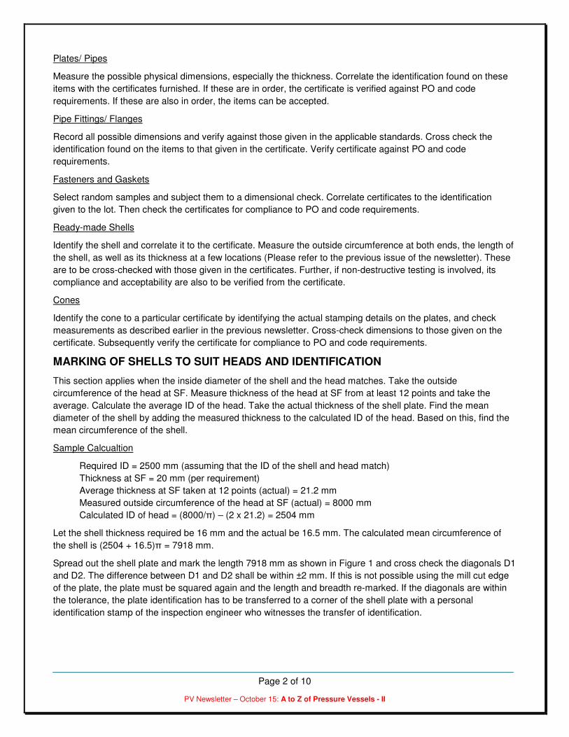
Spread out the shell plate and mark the length 7918 mm as shown in Figure 1 and cross check the diagonals D1
and D2. The difference between D1 and D2 shall be within ±2 mm. If this is not possible using the mill cut edge
of the plate, the plate must be squared again and the length and breadth re-marked. If the diagonals are within
the tolerance, the plate identification has to be transferred to a corner of the shell plate with a personal
identification stamp of the inspection engineer who witnesses the transfer of identification.
Page 3 of 10
PV Newsletter – October 15: A to Z of Pressure Vessels - II
Figure 1: Shell Marking
INSPECTION OF PLATES AFTER CUTTING AND EDGE PREAPRATION
The most commonly used process for the cutting and edge preparation of carbon steel plates is oxyacetylene
cutting, and that for stainless steel plates is plasma-arc cutting. In both cases, the cut edges will have excessive
oxide deposition that is black in color. This has to be removed by grinding, and the acceptable level is at least 1
mm deep into the parent metal so that the detrimental effects due to the presence of oxides shall be completely
removed.
After grinding, the cut edges shall be examined visually for any defects like lamination or any other local defects
due to improper cutting parameters. In cases needed, visual examination of cut edges may be supplemented by
liquid penetrant testing (LPT). When cuts are found satisfactory, the piece can be released for bending.
BENDING OF PLATES
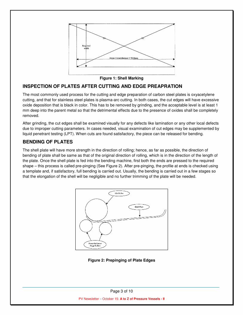
The shell plate will have more strength in the direction of rolling; hence, as far as possible, the direction of
bending of plate shall be same as that of the original direction of rolling, which is in the direction of the length of
the plate. Once the shell plate is fed into the bending machine, first both the ends are pressed to the required
shape – this process is called pre-pinging (See Figure 2). After pre-pinging, the profile at ends is checked using
a template and, if satisfactory, full bending is carried out. Usually, the bending is carried out in a few stages so
that the elongation of the shell will be negligible and no further trimming of the plate will be needed.
Figure 2: Prepinging of Plate Edges

Page 4 of 10
PV Newsletter – October 15: A to Z of Pressure Vessels - II
Templates
The template for checking the profile during bending shall be as per the requirements of UG-29.2, namely twice
the arc length obtained from chart UG-29.2 (See Figure 3). As a rule of thumb, if we take a segmental template
that subtends 20o at the center, it will definitely meet requirements of the ASME clause.
Figure 3: UG-29.2
Set-Up for Welding of Long Seam and Inspection
Upon completion of bending, the longitudinal seam is fitted for welding. Please refer to the August 2013 issue of
the newsletter for the dimensions that shall be recorded for the shell. Apart from those dimensions, the profile all
around the shell shall be checked and deviation in profile form the template beyond acceptable levels shall be
repaired. Additionally, the V-configuration shall be checked for its compliance to the design and its uniformity
throughout the length of the seam (i.e., gap, root face or throat, V angle, etc.).
Precautions to Control Distortion
Distortion of weld joints is more problematic in the case of the longitudinal seams when compared to the
circumferential seams. The usual types of distortion that can take place at a long seam are either peaking in or
peaking out. Given here are a few proposals for the reduction of distortion whose judicious application will yield
positive results.
� When the thickness of the shell plate is less than 16 mm, single-V double welded joints are
recommended. In such cases, the groove shall be provided as far as possible at the inside.
� When the thickness of the shell plate is greater than 16 mm, double-V joints are recommended. In this
case, as far as possible, the joint configuration shall be unequal V with the major V on the inside.
WELDING
Qualified welders shall carry out the welding as per approved procedures. However, every weld has the potential
for distortion – it can’t be avoided. If judicious precautions are taken, distortion is easily brought under
acceptable limits.
Edge Preparation
The edge preparation has a very significant role in controlling distortion. When a rational design of the weld
design is made, the quantum of weld metal is to be minimized, so the quantity of weld on either side of the weld

Page 5 of 10
PV Newsletter – October 15: A to Z of Pressure Vessels - II
can be balanced. Obviously, the associated distortion will also be less. The selection of single or double-V joints
for various thicknesses of shell plate have already been discussed. Even though the V-sizes and angles are
stipulated by the Code, where to apply them and where to do the first welding, etc., are not addressed.
Figure 4: Recommended V-Joint Preparation
Tack Welding of Joints
Tack welding on the seam or the use of clamps and wedges may be resorted to for holding the joint in position.
Provided a qualified welder does the tack weld, using a qualified welding procedure under the requisite
conditions of preheat, it can be a part of the actual weld. In that case, its starting and stopping points shall be
properly prepared by grinding prior to full welding. Tacks shall be provided at a spacing of 200 to 250 mm, with
the length of tack ranging from 25 to 40 mm. The holding devices used for maintaining the shape of shells shall
be retained until the welding from the major-V side is completed, as the distortion is maximum in the first few
passes of the weld.
Run-in and Run-out of Plates
Two pieces of plate of 50 to 100 mm length shall be provided at the beginning and end of each seam, preferably
with the same V-configuration. This will help the welder to start the weld from the run-in plate, and by the time
the welder reaches the shell, welding will be stabilized and the weld on the shell will be free from defects. This is
possible only for longitudinal seams and a serious bearing on the quality of the weld at the start and end of each
longitudinal seam, which eventually turn out to be T-joints.
Stiffeners to maintain Circularity
All sections shall be provided with spiders for maintaining the circularity while rotating the shells on the floor as
well as on rotators. At least four spiders shall be given at both the ends of the shell avoiding the longitudinal
seam area. The spiders can be of angle iron preferably with adjustment provision to maintain the circularity
precisely. Apart from these spiders meant for maintaining circularity, one additional stiffener shall be provided on
the weld with a preset as shown in Figure 5.

Page 6 of 10
PV Newsletter – October 15: A to Z of Pressure Vessels - II
Precleaning of Welds
A weld seam shall be thoroughly cleaned and shall be free from rust, grease, mill scale, or any other foreign
material not only on the weld but also on either side of the V-groove to a width of at least 25 mm. This should be
done meticulously on both sides of the seam prior to the start of the weld on the first side. The use of a circular
wire brush attached to a grinding machine could produce the desired results, whereas the simple wire brush
cleaning is not sufficient as specified in many of the welding procedures.
Figure 5: Restraint on Long Seam for Welding from Outside
Preheating
Based on the material of the shell section and also on the WPS, the joint may have to be preheated prior to
welding. This is given in the Appendix R of the ASME Section VIII, Division 1. Depending on the thickness of the
plate to be welded and the temperature to be attained, suitable attachments shall be made to achieve the same.
The maximum length of the attachment needed is 1000 mm, as it can be moved in the direction of the weld as
the weld progresses. The heating shall be done from the outside when the welding is done from inside and vice
versa.
Sequential Welding
For a longitudinal seam of approximately 1.5 to 2 m long, the weld can start from one end of the seam and finish
at the other. While setting the joint for such welding, care shall be taken to see that the gap provided at the
starting end of the longitudinal seam shall be exactly as per the drawing, and toward the closing end it shall be
increased a bit. For along seam of length 1.5 to 2 m, 2 mm excess gap at the closing end can be given which
will shrink to the desired level as the weld progresses towards the closing end, as shown in Figure 6.
When the length of the seam is more than 2 m, it is better to adopt a staggered welding sequence. For a weld
seam of about 4 m, it is recommended to start welding from one end to a length of about 1 m and next from the
other end for about the same distance. The remaining 2 m left at the center is welded last.
Interpass Cleaning
After every pass, the weld has to be cleaned using proper tools to remove all slag and spatters from the V-
groove. In most cases, power brush cleaning after chipping the slag is sufficient. However, in case of the root
run, it may call for grinding, as it is difficult to remove slag from a deep groove. When the welded surface is free
from slag, spatters and surface defects, it can be taken for depositing subsequent beads after checking the

Page 7 of 10
PV Newsletter – October 15: A to Z of Pressure Vessels - II
interpass temperature. [For any welding to go on, the welded joint shall have a minimum preheat temperature
and at the same time, it shall not exceed the maximum interpass temperature indicated in the WPS]
Figure 6: Longitudinal Seam Fit-Up and Sequence of Welding
Back-Gouging/ Grinding
In the case of longitudinal seams, it is recommended to complete the welding from inside first and then perform
the back-gouging from outside. Back-gouging may be carried out either by carbon electrode gouging or by
grinding alone. In the case of carbon electrode gouging, it shall be ensured that all black carbon gouge marks on
the gouged area are removed by grinding into sound metal by at least 1 mm. This is to prevent the carbon
particles from going into the molten metal, which may cause detrimental effects.
The LPT of the back-gouged joint is always useful in detecting gross defects like lack of fusion, cluster porosity,
slag inclusion, etc., in the root run and hence is recommended for all full penetration welds.
Care should be taken in carrying out the back-gouging so that an unequal V-joint after back-gouging from the
minor side shall never exceed half the thickness of the shell. In other words, the weld from both sides shall be
almost balanced in quantum. In addition, care shall be taken to ensure that the V-width is not increased beyond
that specified in the design. However, the resultant V shall have a V angle of at least 10 to 15o.
Final Visual Examination
On completion of welds on either side, the restraints provided during welding may be removed for ease in
carrying out other jobs. However, the spiders provided to maintain the circularity of shells, especially for thin
shells, may be retained until the vessel is complete so that it can take loads on its own.
The weld joints shall be inspected after the completion of welding from both sides using an inside and outside
template to assess the peaking in or out of the seam. If this is within the acceptable limits as per the code or
client specification, visual inspection of the seam is carried out with regard to the following aspects:
1. Surface finish of the weld and its uniformity according to specifications for welded surfaces permitted in
UW-35. The surface of weld shall be sufficiently free from coarse ripples, grooves, overlaps, and abrupt
ridges and valleys to permit the proper interpretation of radiographs.
2. Reinforcement of weld shall be as per the table given in UW-35.
3. Profile of welded joint
4. Under cuts
5. Spatters
6. Removal of tack metals in the nearby areas.
When all these parameters are satisfactory, the weld can be released for non-destructive testing (NDT) as
needed.

Page 8 of 10
PV Newsletter – October 15: A to Z of Pressure Vessels - II
Non-destructive Testing of Long Seams
All seams that have undergone satisfactory visual inspection can be taken for NDT, the most prominent of which
is RT. As per the applicable specification, UW-11, ultrasonic examination carried out in accordance with UW-53
may be substituted for radiography for the final closure seam of a pressure vessel if the construction of the
vessel does not permit interpretable radiographs. The technique and acceptance criteria shall be in accordance
with Appendix 12 of the ASME Section VIII, Div. 1 code.
Full Radiographic Testing:
The applicable sections of the code in this regard are UW-11 and UW-51. Full radiography is required when joint
efficiency is considered as 1 in the design. In addition, all butt-welds in shells and heads of vessels meant to
carry lethal substances and all butt-welds in shells whose thickness exceeds 38 mm shall also undergo full
radiography.
Spot Radiographic Testing:
The applicable code is UW-52. As per the referred code, one spot on each vessel is required for each 50-ft
increment of weld or fraction thereof. The minimum size of spot shall be 6 in. When such a spot RT film does not
meet the acceptance criteria as specified in UW-51, two additional spots in the same weld away from the initial
spot shall be taken. If these two spots are acceptable and the original spot is repaired and the new radiograph
also meets the acceptability norms, the joint represented by these welds can be considered as accepted. When
either of the additional spots fails to meet the requirements, the entire length of the weld represented by this
weld shall be fully radiographed
The acceptance norms in case of both full and spot radiography are as per UW-51 for linear defects, and
Appendix 4 for rounded indications.
Sources:Sources:Sources:Sources:
1. Practical Guide to Pressure Vessel Manufacturing, by Sunil Pullarcot
*** E N D O F T H E A R T I C L E ***

Page 9 of 10
PV Newsletter – October 15: A to Z of Pressure Vessels - II
About CoDesign Engineering:
CoDesign Engineering specializes in the core business of providing training and consultancy for design and
fabrication of ASME code pressure vessels, and the ecosystem that includes piping, welding, valves, geometric
dimensioning and tolerancing, process improvement, and engineering management. Some of the training
courses (lasting from two days to five days) that we provide include:
• Design and Fabrication of ASME Section VIII, Div. 1 Pressure Vessels
• Design and Fabrication of ASME Section VIII, Div. 2 Pressure Vessels
• Shell & Tube Heat Exchangers - Thermal and Mechanical Design
• ASME Section IX - Welding Technology
• Process and Power Piping
• Engineering Materials
• Renewable Energy - Solar & Biogas
We also provide several one-day workshops:
• Know Your Power Piping
• Know Your Process Piping
• Know Your ASME Section VIII Pressure Vessel Code
• Know Your Shell & Tube Heat Exchangers
• A to Z of Pressure Vessels
• Transitioning to ASME Section VIII, Div. 2
Our trainings can be offered at most cities worldwide.
Contact [email protected] for the training calendar and rates.
Visit our website www.codesignengg.com for contents of the courses.

Page 10 of 10
PV Newsletter – October 15: A to Z of Pressure Vessels - II
Did you like this article?Did you like this article?Did you like this article?Did you like this article?
I would request you to provide me your feedback on the article in this newsletter (and the previous
newsletters as well). I would also request you to send me email addresses for your acquaintances
that would benefit by receiving this newsletter. If you would like to contribute articles, please let me
know. Finally, if you would like the newsletter to be sent to a different email address, or not receive it
at all, kindly email at [email protected].
Ramesh Tiwari holds a Master’s degree in Mechanical Engineering from Clemson University in South Carolina, and
is a registered Professional Engineer from the state of Maryland in the United States. He has over 22 years of
experience designing pressure vessels, heat exchangers and tanks. Ramesh is a member of ASME Section VIII
Subgroup on Heat Transfer Equipment, and member of ASME B31.1 IWG for Power Piping. He is also an approved
pressure vessel instructor at National Thermal Power Corporation (NTPC), a premier thermal power generating
company in India; and TUV India of TUV Nord Group, one of the world’s largest Inspection, Certification and Testing
Organizations.
Disclaimer: I feel it is necessary to place a disclaimer statement to protect myself, the contributors and the newsletter. The information provided in this newsletter is for educational purpose only. As a qualified engineer, I take this opportunity to remind all potential users of the information contained herein that it is YOUR responsibility to ensure that all designs are verified, and that such designs comply with the current editions of the relevant codes. I will accept no liability for any loss or damage which may result from improper use of information in this newsletter.