Embed Size (px)
Citation preview
Page 1 of 12
PV Newsletter – February 2013: Classification of Shell and Tube Heat Exchangers
February 15, 2013 www.codesignengg.com
PV NewsletterPV NewsletterPV NewsletterPV Newsletter Monthly Publication from CoDesign Engineering Skills Academy
Classification of Shell-and-Tube Heat Exchangers
Shell-and-tube heat exchangers can be classified based on construction, or on service. Both classifications are
discussed in the paragraphs below.
Classification based on construction
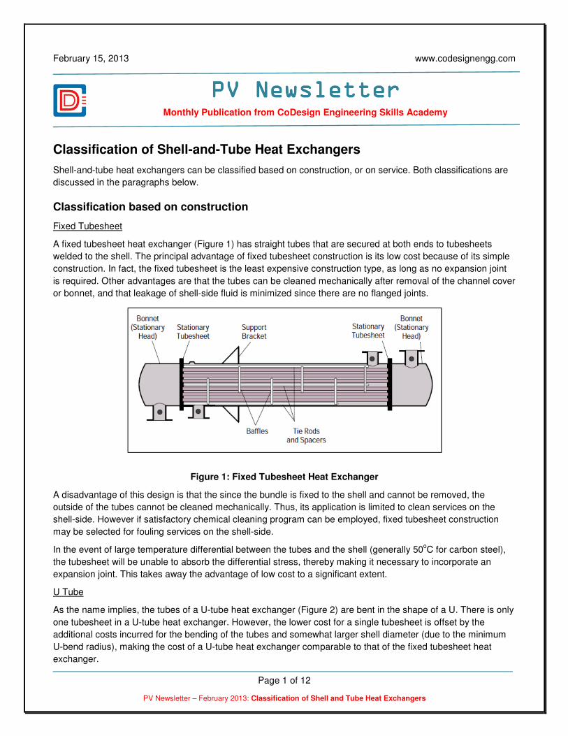
Fixed Tubesheet
A fixed tubesheet heat exchanger (Figure 1) has straight tubes that are secured at both ends to tubesheets
welded to the shell. The principal advantage of fixed tubesheet construction is its low cost because of its simple
construction. In fact, the fixed tubesheet is the least expensive construction type, as long as no expansion joint
is required. Other advantages are that the tubes can be cleaned mechanically after removal of the channel cover
or bonnet, and that leakage of shell-side fluid is minimized since there are no flanged joints.
Figure 1: Fixed Tubesheet Heat Exchanger
A disadvantage of this design is that the since the bundle is fixed to the shell and cannot be removed, the
outside of the tubes cannot be cleaned mechanically. Thus, its application is limited to clean services on the
shell-side. However if satisfactory chemical cleaning program can be employed, fixed tubesheet construction
may be selected for fouling services on the shell-side.
In the event of large temperature differential between the tubes and the shell (generally 50oC for carbon steel),
the tubesheet will be unable to absorb the differential stress, thereby making it necessary to incorporate an
expansion joint. This takes away the advantage of low cost to a significant extent.
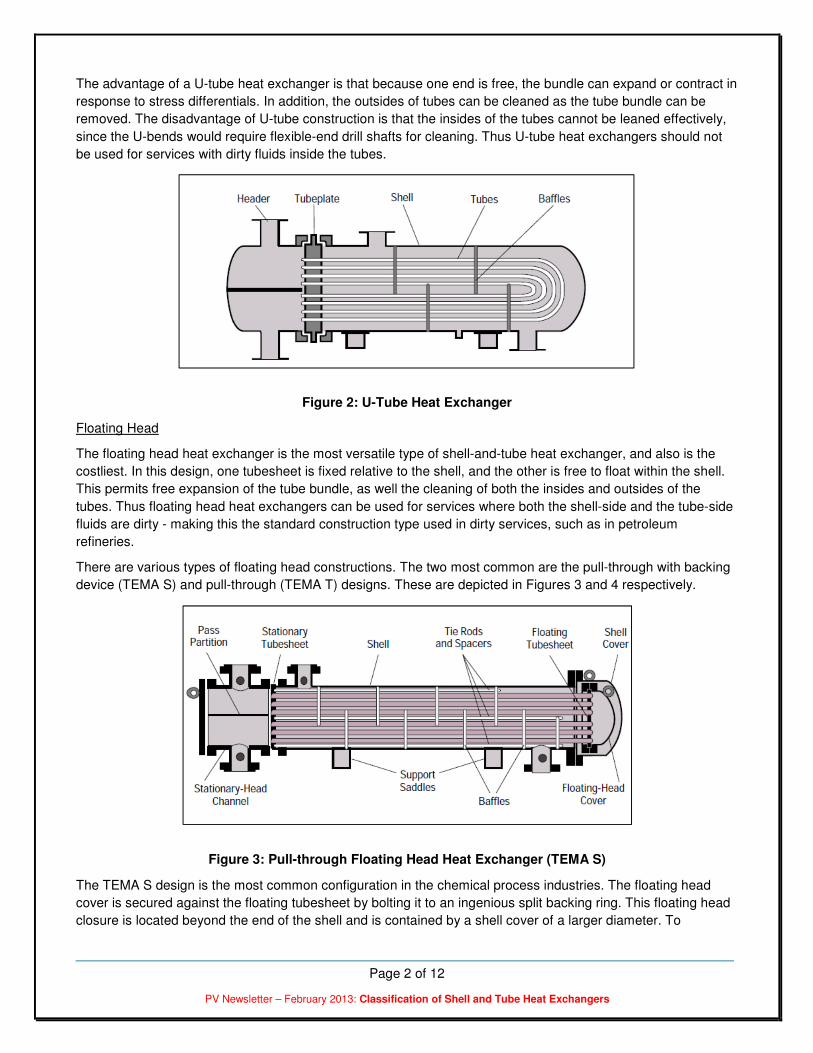
U Tube
As the name implies, the tubes of a U-tube heat exchanger (Figure 2) are bent in the shape of a U. There is only
one tubesheet in a U-tube heat exchanger. However, the lower cost for a single tubesheet is offset by the
additional costs incurred for the bending of the tubes and somewhat larger shell diameter (due to the minimum
U-bend radius), making the cost of a U-tube heat exchanger comparable to that of the fixed tubesheet heat
exchanger.
Page 2 of 12
PV Newsletter – February 2013: Classification of Shell and Tube Heat Exchangers
The advantage of a U-tube heat exchanger is that because one end is free, the bundle can expand or contract in
response to stress differentials. In addition, the outsides of tubes can be cleaned as the tube bundle can be
removed. The disadvantage of U-tube construction is that the insides of the tubes cannot be leaned effectively,
since the U-bends would require flexible-end drill shafts for cleaning. Thus U-tube heat exchangers should not
be used for services with dirty fluids inside the tubes.
Figure 2: U-Tube Heat Exchanger
Floating Head
The floating head heat exchanger is the most versatile type of shell-and-tube heat exchanger, and also is the
costliest. In this design, one tubesheet is fixed relative to the shell, and the other is free to float within the shell.
This permits free expansion of the tube bundle, as well the cleaning of both the insides and outsides of the
tubes. Thus floating head heat exchangers can be used for services where both the shell-side and the tube-side
fluids are dirty - making this the standard construction type used in dirty services, such as in petroleum
refineries.
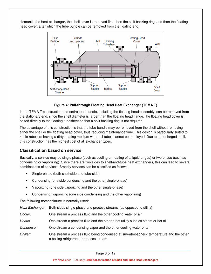
There are various types of floating head constructions. The two most common are the pull-through with backing
device (TEMA S) and pull-through (TEMA T) designs. These are depicted in Figures 3 and 4 respectively.
Figure 3: Pull-through Floating Head Heat Exchanger (TEMA S)
The TEMA S design is the most common configuration in the chemical process industries. The floating head
cover is secured against the floating tubesheet by bolting it to an ingenious split backing ring. This floating head
closure is located beyond the end of the shell and is contained by a shell cover of a larger diameter. To
Page 3 of 12
PV Newsletter – February 2013: Classification of Shell and Tube Heat Exchangers
dismantle the heat exchanger, the shell cover is removed first, then the split backing ring, and then the floating
head cover, after which the tube bundle can be removed from the floating end.
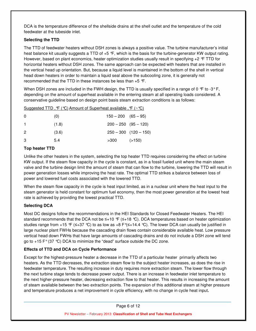
Figure 4: Pull-through Floating Head Heat Exchanger (TEMA T)
In the TEMA T construction, the entire tube bundle, including the floating head assembly, can be removed from
the stationary end, since the shell diameter is larger than the floating head flange.The floating head cover is
bolted directly to the floating tubesheet so that a split backing ring is not required.
The advantage of this construction is that the tube bundle may be removed from the shell without removing
either the shell or the floating head cover, thus reducing maintenance time. This design is particularly suited to
kettle reboilers having a dirty heating medium where U-tubes cannot be employed. Due to the enlarged shell,
this construction has the highest cost of all exchanger types.
Classification based on service
Basically, a service may be single phase (such as cooling or heating of a liquid or gas) or two phase (such as
condensing or vaporizing). Since there are two sides to shell-and-tube heat exchangers, this can lead to several
combinations of services. Broadly services can be classified as follows:
• Single-phase (both shell-side and tube-side)
• Condensing (one side condensing and the other single-phase)
• Vaporizing (one side vaporizing and the other single-phase)
• Condensing/ vaporizing (one side condensing and the other vaporizing)
The following nomenclature is normally used:
Heat Exchanger: Both sides single phase and process streams (as opposed to utility)
Cooler: One stream a process fluid and the other cooling water or air
Heater: One stream a process fluid and the other a hot utility such as steam or hot oil
Condenser: One stream a condensing vapor and the other cooling water or air
Chiller: One stream a process fluid being condensed at sub-atmospheric temperature and the other
a boiling refrigerant or process stream

Page 4 of 12
PV Newsletter – February 2013: Classification of Shell and Tube Heat Exchangers
Reboiler: One stream a bottoms stream from a distillation column and the other a hot utility (steam or
hot oil) or a process stream
Sources:Sources:Sources:Sources:
1. Effectively Design Shell-and-Tube Heat Exchangers by Rajiv Mukherjee
*** E N D O F T H E A R T I C L E ***
Bonus Article
The Power Plant Steam Cycle by Stanley Yokell
INTRODUCTION
This brief article is based upon the course notes that Carl F. Andreone and the author prepared for the course
that we jointly present to power plant engineers for many years.
Power plants are designed to produce power at the lowest cost of input energy that will produce the desired
output of kilowatts (KWs). Their designs are based upon estimates of the cost of fuel to make the steam that
feeds the turbine-generator system and the selling price of the output KWs over the projected life of the plant.
Usually the utility owner selects the turbine-generator set and the steam generator needed to supply the steam
to the turbine-generator. The AE then optimizes the BOP design. In addition to the building design the BOP
design includes the optimization of the main steam condenser, pumps and feedwater heaters. The figures in
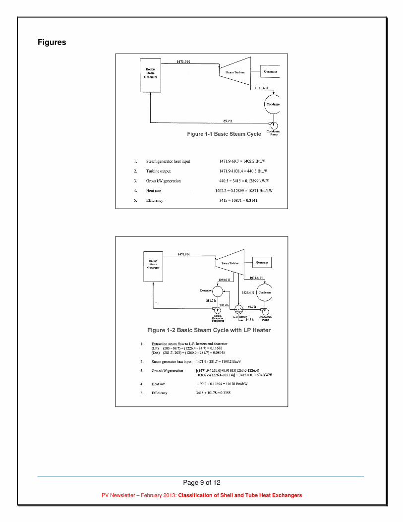
this chapter use typical data to illustrate the steam cycle.
In the basic steam cycle (Fig.1-1) steam exits the steam generator and enters the main turbine at high
temperature and pressure. Steam expands through the turbine thus producing usable shaft power that is
transferred to the generator to produce output KW. The steam that exits the turbine exhaust is condensed to
water in the main condenser. From there it is pumped back to the steam generator. Heat energy is added in the
steam generator to produce high temperature high-pressure steam and the cycle repeats itself.
The steam cycle efficiency can be improved by raising the feedwater temperature that enters the inlet of the
steam generator. The higher the feedwater temperature is raised, the more efficient the cycle will be. To
achieve this increase in efficiency heat exchangers (FWHs) are installed in the feedwater flow path between the
condenser and the steam generator. (Fig. 1-2) Steam, extracted from the turbine at various pressure levels, is
fed to the shell sides of the FWHs to heat the feedwater which flows through the tubes. The improvement in the
plant heat rate when additional heaters are placed in the feedwater flow path to increase the feedwater
temperature to the steam generator is shown in (Fig. 1-3).
Another commonly used method to raise steam cycle efficiency is to take partially expanded steam which is still
at relatively high pressure from the turbine and return it to the steam generator to be reheated. This steam is
then reintroduced to the turbine at an appropriate lower pressure admission point where its power producing
expansion is continued.
TYPES OF FWHs
Two types of feedwater heaters are in use in most power plants: The “direct contact” or “open” type and the
“shell and tube” or “closed” type. This article deals with the closed feedwater heater type. However, it briefly
discusses direct contact type (Deaerators).

Page 5 of 12
PV Newsletter – February 2013: Classification of Shell and Tube Heat Exchangers
Deaerators
Deaerators heat the feedwater to the saturation temperature of the extraction steam being supplied to the
heater. In addition to heating the feedwater the Deaerator removes dissolved gases in the feedwater in order to
lower the oxygen content to desired levels to minimize corrosion in the system. It also provides a large storage
volume at the suction of the feed pump to provide some cool down time when the plant is tripped to minimize
excessive thermal transients in the boiler/steam generator.
Closed FWHs
The second type of FWH is the closed feedwater heater discussed in the following.. These are arranged in the
following broad classifications:
Single-Zone Steam condensing only
Two-Zone Steam condensing with condensate subcooling, or
Steam desuperheating with steam condensing
Three-Zone Steam desuperheating, steam condensing, and condensate subcooling.
The Heat Exchange Institute (HEI) Closed Feedwater Heater Standards have illustrations of zone arrangements
and heater installation positions.
Single zone heaters
Single zone FWHs usually take extraction steam from the lowest pressure end of the turbine. They are
condensing only heaters. Using heaters with a subcooling zone to heat feedwater with extraction steam from the
lowest pressure stage of the turbine must be evaluated carefully over the complete anticipated operating range
of the plant. The low-load operating conditions often result in such low extraction pressure steam as to make the
hydraulics of a subcooling zone marginal. In such cases, an external subcooler might be included in the cycle.
Two-zone heaters
When extraction steam pressures are higher at all considered loads, a subcooling zone will improve the heat
rate. With one exception it is always included. The one exception is when condensate from the heater is pumped
forward into the feedwater stream. In this circumstance no subcooling is appropriate because the energy in the
condensate is going directly into the feedwater stream. For this exception the location of the pump relative to the
heater must be such that it precludes the need for a subcooling zone to protect the pump from flashing
condensate at the pump inlet.
Three zone heaters
In fossil fuel power plants steam leaves the boiler with great amounts of superheat. Consequently even after the
steam has been partially expanded in the high pressure stages of the turbine, extraction steam entering the
shells of the high pressure heaters can have as much as 100 °F to 400
°F of superheat. When extraction steam
has sufficient amount of superheat, at all loads considered, a three zone heater that includes a DSH zone will be
provided. This reduces the amount of steam extraction required to raise the temperature of the feedwater,
thereby further improving the heat rate.
THERMAL PERFORMANCE
The thermal performance of closed feedwater heaters is measured by two values, the TTD and the DCA. Their
definitions are repeated here.
TTD is the temperature difference between the saturation temperature corresponding to the inlet steam pressure
at the shell inlet and the temperature of the feedwater at the tubeside outlet.
Page 6 of 12
PV Newsletter – February 2013: Classification of Shell and Tube Heat Exchangers
DCA is the temperature difference of the shellside drains at the shell outlet and the temperature of the cold
feedwater at the tubeside inlet.
Selecting the TTD
The TTD of feedwater heaters without DSH zones is always a positive value. The turbine manufacturer’s initial
heat balance kit usually suggests a TTD of +5 °F, which is the basis for the turbine-generator KW output rating.
However, based on plant economics, heater optimization studies usually result in specifying +2 °F TTD for
horizontal heaters without DSH zones. The same approach can be expected with heaters that are installed in
the vertical head up orientation. But, because a liquid level is maintained in the bottom of the shell in vertical
head down heaters in order to maintain a liquid seal above the subcooling zone, it is generally not
recommended that the TTD in these instances be less than +5 °F.
When DSH zones are included in the FWH design, the TTD is usually specified in a range of 0 °F to -3° F,
depending on the amount of superheat available in the entering steam at all operating loads considered. A
conservative guideline based on design point basis steam extraction conditions is as follows:
Suggested TTD ,°F (°C) Amount of Superheat available ,°F (~°C)
0 (0) 150 – 200 (65 – 95)
1 (1.8) 200 – 250 (95 – 120)
2 (3.6) 250 – 300 (120 – 150)
3 5.4 >300 (>150)
Top heater TTD
Unlike the other heaters in the system, selecting the top heater TTD requires considering the effect on turbine
KW output. If the steam flow capacity in the cycle is constant, as in a fossil fueled unit where the main steam
valve and the turbine design limit the amount of steam that can flow to the turbine, lowering the TTD will result in
power generation losses while improving the heat rate. The optimal TTD strikes a balance between loss of
power and lowered fuel costs associated with the lowered TTD.
When the steam flow capacity in the cycle is heat input limited, as in a nuclear unit where the heat input to the
steam generator is held constant for optimum fuel economy, then the most power generation at the lowest heat
rate is achieved by providing the lowest practical TTD.
Selecting DCA
Most DC designs follow the recommendations in the HEI Standards for Closed Feedwater Heaters. The HEI
standard recommends that the DCA not be ≤+10 °F (≤+18 °C). DCA temperatures based on heater optimization
studies range from +15 °F (≤+37 °C) to as low as +8 F°(≤+14.4 °C). The lower DCA can usually be justified in
large nuclear plant FWHs because the cascading drain flows contain considerable available heat. Low pressure
vertical head down FWHs that have large amounts of cascading drains and do not include a DSH zone will tend
go to +15 F° (37 °C) DCA to minimize the “dead” surface outside the DC zone.
Effects of TTD and DCA on Cycle Performance
Except for the highest-pressure heater a decrease in the TTD of a particular heater primarily affects two
heaters. As the TTD decreases, the extraction steam flow to the subject heater increases, as does the rise in
feedwater temperature. The resulting increase in duty requires more extraction steam. The lower flow through
the next turbine stage tends to decrease power output. There is an increase in feedwater inlet temperature to
the next higher-pressure heater, decreasing extraction flow to that heater. This results in increasing the amount
of steam available between the two extraction points. The expansion of this additional steam at higher pressure
and temperature produces a net improvement in cycle efficiency, with no change in cycle heat input.

Page 7 of 12
PV Newsletter – February 2013: Classification of Shell and Tube Heat Exchangers
At the highest-pressure heater, a decrease in heater TTD has a somewhat different effect. When the turbine
steam flow is constant, the lower flow through the next turbine stage will decrease the power output. However,
since the feedwater temperature to the economizer is higher and the reheater duty is lower, the lower heat input
to the boiler will have to be evaluated against the KW output loss to determine the optimal TTD.
Except for the highest-pressure heater a decrease in the DCA of a particular heater actually affects three
heaters. The extraction steam flow to a particular heater will decrease slightly as the duty in the DCA zone
increases and warmer feedwater enters the condensing zone. Not as much steam is extracted from the turbine,
which increases the power output. The additional steam flow within the next turbine stage results in a small
increase in the extraction pressure of the subject heater thereby slightly increasing the feedwater outlet
temperature.
The higher feedwater inlet temperature to the next higher-pressure heater results in lowering the extraction
steam flow to that heater. At the same time, the cooler drains are cascaded to the next lower pressure heater,
slightly increasing the extraction load. The net effect to the cycle is an increase in output and cycle efficiency
because expansion of more steam at higher pressure and temperature produces more work. Note that there will
be no change in heat input.
Lowering the DCA of the highest-pressure heater will slightly reduce the amount of steam extraction to the
heater with a corresponding slight increase in the power output. The reheater duty will increase slightly, however
the slightly higher feedwater temperature resulting from the same type of extraction pressure increase discussed
above may or may not overcome this deficit which will impact the heat input to the boiler. It is cycle-dependent
still the net effect is improved cycle efficiency and output.
Effects of TTD and DCA on Performance
Lowering either the TTD or DCA will increase cycle efficiency. The increase will usually be manifested either by
an increase in power output, a decrease in heat input, or a combination of the two. In the special case of the
highest pressure heater the decrease in power output resulting from a lowered TTD must have a more than
compensating decrease in heat input in order to be acceptable.
The TTD and DCA represent cost factors that affect the ability of a feedwater heater design to save fuel or to
produce more power. When applied, the design may be charged or credited with a performance dollar value that
may be used to optimize the heater performance parameters.
In addition, the tubeside pressure drop must be considered in the overall heater performance cost because it
determines the cost of pumping power used to force the feedwater through the heaters. The value of the
pressure drop cost and the way it is calculated is cycle dependent.
Feedwater pumps that feed heaters located between the main condenser and the Deaerator are usually motor-
driven. The pumping costs will be costs of the difference in auxiliary power used by the condensate pumps to
overcome the feedwater heater pressure drop. For the heaters between the Deaerator and the steam generator
it will consist of the cost difference brought about by the added extraction steam required by the main feed-pump
turbine to overcome the feedwater heater pressure drop. With feedwater reheat cycles that do not have a
Deaerator the condensate pump supplies the necessary net positive suction head (NPSH) for the intermediate
pressure feed-pump and/or the high-pressure feed-pump.
Combining the costs associated with heat input, power output, and pressure drop allows a total performance
evaluation to be made of the performance parameters of a specific heater.
Effects of TTD and DCA on Heater Size
The improvement of feedwater heater TTD and DCA will result in an increase in the heat transfer area required
to meet the increased duty. If the space is available, the heater diameter can be held unchanged and the tube
length allowed to increase to accommodate the increase in heat transfer surface required. This will result in an

Page 8 of 12
PV Newsletter – February 2013: Classification of Shell and Tube Heat Exchangers
increase in tubeside pressure drop. If the length becomes too long, the diameter can be increased to
accommodate more tubes to satisfy the increased heat transfer surface requirements. This will result in lower
tubeside pressure drop.
Effects of Tube Size and Material on Heater Size
With a given length restriction smaller diameter tubes will accommodate more heat transfer surface in a given
shell diameter. This will result in an increase in tubeside pressure drop.
The tubeside pressure drop in a heater can be lowered by using larger diameter tubes. This will require a larger
shell diameter than would be required for an equal surface area of smaller diameter tubes.
When considering prices when buying FWHs keep in mind that longer is less expensive for designs that satisfy
the performance requirements.
Tube materials with low thermal conductivity characteristics, such as austenitic stainless steels, require more
heat transfer surface than ones with high thermal conductivity such as ferrous and non-ferrous tubes to satisfy
the performance requirements
Effects of TTD and DCA on Heater Cost
Any decrease in either TTD or DCA will cause an increase in heat transfer area, with an attendant increase in
cost. The lowering of the TTD from +5 °F (9°C) to +2
°F (3.6 °C) in a heater without a DSH zone will increase the
cost by about 25%. This is usually acceptable based on plant economics. The lowering of the TTD from 0 °F to
-3 °F(≤+37 °C) in a heater with a DSH zone will increase the cost by approximately 5-10% per degree in this
range.
The incremental cost of a lower DCA is generally unacceptable when lowering the DCA below the 15 °F to 10 °F
(27 to 18 °C) range. Base loaded plants will optimize with +10 °F(18°C) , while cycling plants will probably settle
at +15 °F (27 °C) , as well as in vertical head down heaters without a DSH zone. A large plant of about 1000
megawatts (MW) or more, may be able to justify +8 ° (14.4°C)F.
Feedwater Heater Optimization
With all of the above costs and physical limitations either known or easily calculable, optimal values of TTD and
DCA can be assigned that represent the best choice of heaters for a particular cycle.
The procedure is to optimize the TTD and DCA separately for each heater. This must be done several times for
a given cycle to ensure that convergence has been achieved at all heaters. Occasionally, the optimal value(s)
for a given heater will change as a result of the optimization of an adjacent heater.
Consideration must be given to physical constraints. If the length of an optimized heater is too great, it will have
to be resized with a lower tubeside velocity. This would make the heater diameter larger while decreasing its
length. It would not be the lowest cost heater but it would be the best choice, all things considered.
Capitalized performance costs are combined with estimated capital costs in the pre-bid stage to arrive at the
lowest total evaluated costs (Fig.1-4). The heaters can then be specified with the optimized TTD and DCA
values.
Page 9 of 12
PV Newsletter – February 2013: Classification of Shell and Tube Heat Exchangers
Figures

Page 10 of 12
PV Newsletter – February 2013: Classification of Shell and Tube Heat Exchangers

Page 11 of 12
PV Newsletter – February 2013: Classification of Shell and Tube Heat Exchangers
Sources:Sources:Sources:Sources:
1. “The Choice Of Terminal Temperature Difference for Closed Feedwater Heaters in a Steam Cycle”, P.A.
D’Errico and C.F. Andreone, IEEE/ASME JPGC , Oct. 1989
2. HEI, “Standards for Closed Feedwater Heaters”, 8th Ed., The Heat Exchange Institute, Cleveland, Ohio
*** E N D O F T H E A R T I C L E ***
About CoDesign Engineering:
CoDesign Engineering specializes in the core business of providing training and consultancy for design and
fabrication of ASME code pressure vessels, and the ecosystem that includes piping, welding, valves, geometric
dimensioning and tolerancing, process improvement, and engineering management. Some of the training
courses (lasting from two days to five days) that we provide include:
• Design and Fabrication of ASME Section VIII, Div. 1 Pressure Vessels
• Design and Fabrication of ASME Section VIII, Div. 2 Pressure Vessels
• Shell & Tube Heat Exchangers - Thermal and Mechanical Design
• ASME Section IX - Welding Technology
• Engineering Management
We also provide several one-day workshops:
• Know Your Power Piping
• Know Your Process Piping
• Know Your ASME Section VIII Pressure Vessel Code
• Know Your Shell & Tube Heat Exchangers
• A to Z of Pressure Vessels
• Transitioning to ASME Section VIII, Div. 2
Our trainings can be offered at most cities in India and in US.
Please contact [email protected] for the training calendar and rates.
Visit our website www.codesignengg.com for contents of the courses.

Page 12 of 12
PV Newsletter – February 2013: Classification of Shell and Tube Heat Exchangers
Did you like this article?Did you like this article?Did you like this article?Did you like this article?
I would request you to provide me your feedback on the article in this newsletter (and the previous
newsletters as well). I would also request you to send me email addresses for your acquaintances
that would benefit by receiving this newsletter. If you would like to contribute articles, please let me
know. Finally, if you would like the newsletter to be sent to a different email address, or not receive it
at all, kindly email me at [email protected].
Ramesh Tiwari holds a Master’s degree in Mechanical Engineering from Clemson University in South Carolina, and
is a registered Professional Engineer from the state of Maryland in the United States. He has over 22 years of
experience designing pressure vessels, heat exchangers and tanks. Ramesh is a member of ASME Section VIII
Subgroup on Heat Transfer Equipment, and member of ASME B31.1 IWG for Power Piping. He is also an approved
pressure vessel instructor at National Thermal Power Corporation (NTPC), a premier thermal power generating
company in India.
Disclaimer: I feel it is necessary to place a disclaimer statement to protect myself, the contributors and the newsletter. The information provided in this newsletter is for educational purpose only. As a qualified engineer, I take this opportunity to remind all potential users that it is YOUR responsibility to ensure that all designs are verified, and that such designs comply with the current editions of the relevant codes. I accept no liability for any loss or damage which may result from improper use of information in this newsletter.