Embed Size (px)
Citation preview
1 www.megger.com MeggerELECTRICALTESTERJuly2011
Damon MountSales Manager
ELECTRICALTESTER The industry’s recognised information tool
Published by Megger July 2011
An insight into the Newbury horse tragedy
Mark JohnsonUK Marketing Communications Manager
What is primary current injection testing, and what are its applications? What kind of test equipment is needed for primary injection testing, and what features should users expect to find in the latest test sets? The answers to these questions and many more are supplied by Damon Mount of Megger.
Primary current injection testing is usually associated with high current and high voltage power distribution systems of the type found in an electricity substation, or in a large industrial installation. While there is some mystique about this form of testing, the principle that underlies it is actually very straightforward: a test current is injected into the primary side of a system – which is often but not always some form of protection scheme – to determine how the system behaves at particular levels of current.
The system under test might, for example, comprise a circuit breaker with an over-current trip relay that operates via a current transformer (CT). By injecting a predetermined current into the circuit breaker, it is possible to determine whether the relay will trip at this current and if so, how long the current needs to flow before the trip is initiated.
Something similar, of course, could be achieved by injecting a test current directly into the trip relay – that is, on the secondary side of the CT. This is secondary current injection testing and it is widely used, not least because much lower currents are needed than are typically required for primary injection testing.
Secondary injection testing Undoubtedly valuable, but secondary injection testing does not check all of the components in the system. In the scenario discussed, it would not reveal a defective CT. Neither does it truly mimic in service the operating conditions – the heating effect of the primary current will not be present and in some types of test, this can significantly affect the results obtained.
For these reasons, there are many situations where primary injection testing is considered useful if not essential. Because it tends to be somewhat disruptive – the plant under
test must be taken out of service and de-energised and then arrangements must be made for the high current connections needed for the test – primary injection is most usually performed as part of the commissioning procedure for new plant or after major modifications have been carried out. In some instances, however, it can also be an invaluable aid to faultfinding.
Test sets used for primary injection These are invariably built specifically for this purpose. Their primary function is to supply a lot of current – tests typically involve injecting currents from 100 A up to 20,000 A. Equipment capable of delivering these sorts of currents is never going to be physically small or lightweight, but remarkable strides have been made over
recent years in making primary injection test sets more manageable.
One way this has been achieved is by using modular current sources, so that for lower test currents only one or two sources are needed, but for higher test currents additional current sources can be added.
Test sets that adopt this approach are often assembled on wheeled trolleys that can accommodate the control unit plus up to three or four current source modules. This arrangement makes the test sets much easier to handle.
Test equipment manufacturers have also noted that only a few applications of primary injection testing involve the highest
currents – many requirements can be satisfied with test sets rated at no more than 5000 A, which paves the way for smaller mid-range units. In addition, the highest currents are usually only required for a comparatively short time for example to test an instantaneous over-current relay, so the test sets do not need to be continuously rated for their maximumcurrent output. Once again, this allows size and weight to be reduced.
Weight and size are not the only areas where progress has been made. Another useful development is the introduction of test sets where the control unit can be connected to the current generator by a comparatively long control cable.
continued on page 2
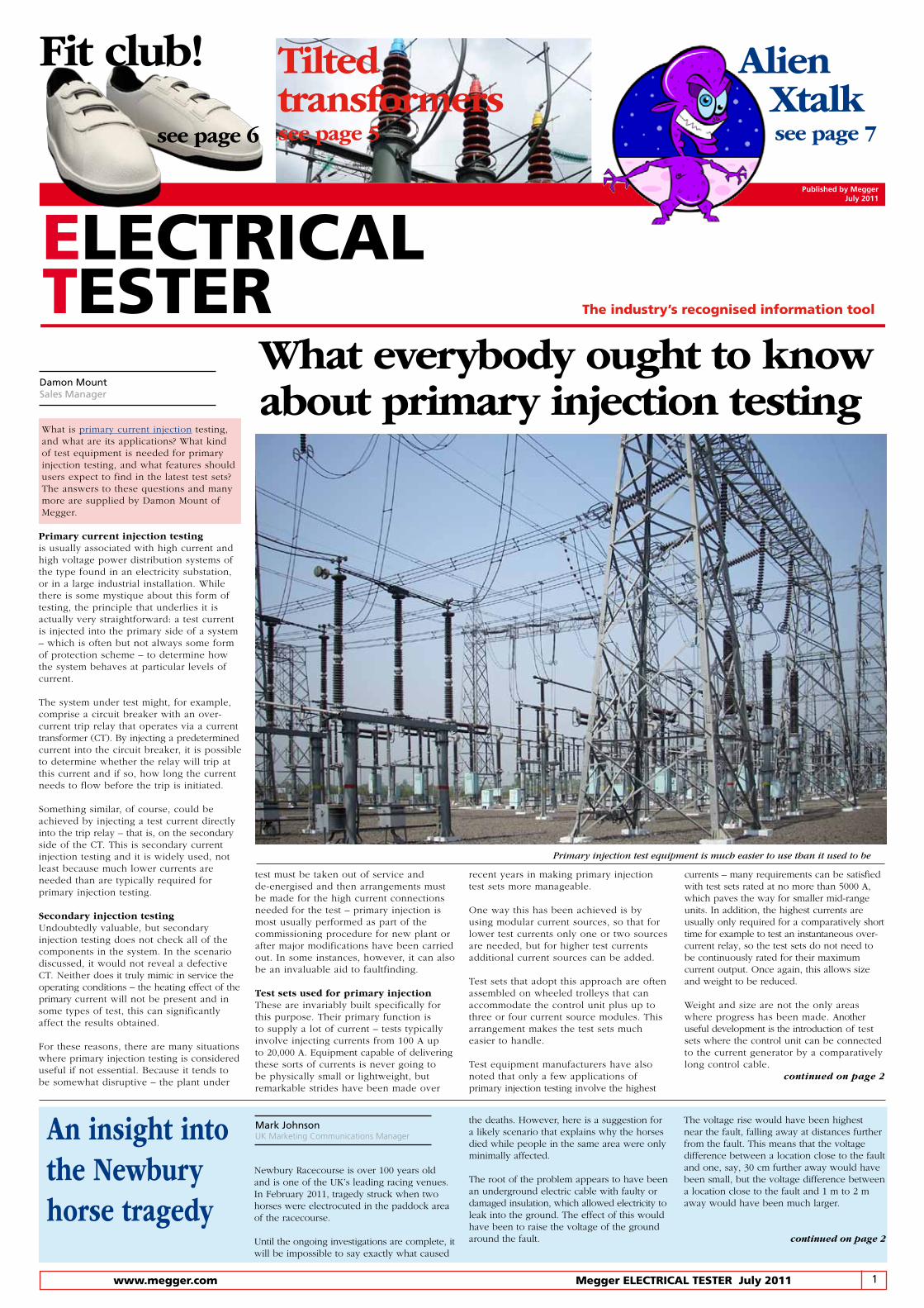
Primary injection test equipment is much easier to use than it used to be
Newbury Racecourse is over 100 years old and is one of the UK’s leading racing venues. In February 2011, tragedy struck when two horses were electrocuted in the paddock area of the racecourse.
Until the ongoing investigations are complete, it will be impossible to say exactly what caused
the deaths. However, here is a suggestion for a likely scenario that explains why the horses died while people in the same area were only minimally affected.
The root of the problem appears to have been an underground electric cable with faulty or damaged insulation, which allowed electricity to leak into the ground. The effect of this would have been to raise the voltage of the ground around the fault.
The voltage rise would have been highest near the fault, falling away at distances further from the fault. This means that the voltage difference between a location close to the fault and one, say, 30 cm further away would have been small, but the voltage difference between a location close to the fault and 1 m to 2 m away would have been much larger.
continued on page 2
Tilted transformerssee page 5
What everybody ought to know about primary injection testing
Fit club!
see page 6
Alien Xtalk see page 7

2 MeggerELECTRICALTESTERJuly2011 www.megger.com
Contents
Editor Nick Hilditch. T +44 (0)1304 502232E [email protected] www.megger.com
Megger LimitedArchcliffe Road Dover Kent CT17 9ENT +44 (0)1304 502100E [email protected] www.megger.com
‘Views expressed in Electrical Tester are not necessarily the views of Megger.’
The word ‘Megger’ is a registered trademark
Note from the Editor
Time for your say. We have introduced a ‘Questions and Answers’ section and would like your input. If you have any questions or stories that you think we could use, then please email [email protected]
A printed newsletter is not as interactive as its email equivalent so to help you find items quickly on www.megger.com, we have underlined key search words in blue.
The industry’s recognised information toolELECTRICAL
TESTER
The rights of the individuals attributed in Electrical Tester to be identified as authors of their respective articles has been asserted by them in accordance with the Copyright, Designs and Patents Act 1988.
© Copyright Megger. All rights reserved. No part of Electrical Tester may be reproduced in a retrieval system, or transmitted in any form or by any means, electronic, mechanical, photo-copying, recording or otherwise without the prior written permission of Megger.
To request a licence to use an article in Electrical Tester, please email [email protected], with a brief outline of the reasons for your request.
All trademarks used herein are the property of their respective owners. The use of any trademark in this text does not imply trademark ownership rights in such trademarks, nor does use of such trademarks imply any affiliation with or endorsement of Electrical Tester by such owners.
What everybody ought to know about primary injection testing ......... 1Damon Mount, Sales Manager
An insight into the Newbury horsetradgey............................................... 1Mark Johnson, UK Marketing Communication Manager
Does the CAT fit? ............................... 3Bryan Phillips, Market Development Manager
Two shows, one theme ...................... 3
The past of PAXMatz Ohlen, Director of Transformer Testing .. 3
Trouble with trends? ......................... 4Paul Swinerd, Product Portfolio Manager
Tilted transformers ............................ 5Alan Purton, Applications Engineer
Fit club for transformers ................... 5
High velocity STATES ........................ 6
Alien Crosstalk Part 1 ....................... 6Mark Bartmettler, Product Manager
Metreport ........................................... 7Andrew Sagl, Product Manager
Q&A ................................................... 8Jeff Jowett, Applications Engineer
Ask Jowett ......................................... 8Jeff Jowett, Applications Engineer
All at sea with SS Shieldhall .............. 8Simon Wood, UK Distribution Sales Manager
continued from page 1
This allows the current generator to be placed very close to the equipment under test, thereby minimising the length of the high current test leads needed, which makes testing easier and more practical.
To ensure versatility, primary injection test sets need to be able to offer options to cope with a wide range of burdens since, if they do not, there is the possibility that they will not be able to deliver the required test current into the impedance presented by the equipment under test plus the test cables. In the best test sets, this issue is addressed by allowing the output voltage of the current generators to be raised at the expense of output current, so that the total power the test set is required to deliver is not increased unduly. This option is particularly valuable when testing CTs, circuit breakers and busbar joints.
Another option of great value is an integral timer that can be set to inject the test current for an accurately controlled time, preset by the user. This makes it easy to perform complete circuit breaker tripping time tests that encompass both the relay and the CTs, by injecting the actual fault currents. Auxiliary voltage and current measuring inputs facilitate the testing of CTs and good test sets can provide a wide range of data, including impedance, resistance, virtual power, active power, reactive power, and power factor, together with CT ratio and polarity.
A fast acting hold feature for the measuring functions, which is provided in conjunction with a “stop” input further enhances useful-ness, as it allows readings to be frozen by applying a signal to the stop input. This makes it possible, for example, to record data relating to the exact moment that a
protection relay operates during a test. Some instruments, when used for circuit breaker testing, can even be configured to automatically freeze the measurements at the instant the breaker trips without the need to use the stop input.
A feature that is just starting to become available on the latest primary injection test sets is zero-crossover synchronisation. This ensures that the test current is turned on only at a zero crossing point, which eliminates d.c. offset effects and also ensures the best possible repeatability for test results.
One issue that has been perennially troublesome in carrying out primary injection tests has been heating of the equipment under test while setting up and adjusting the test current. This effect has even been known to trip a breaker under test during set up before the test proper has commenced. Work-arounds are available – test engineers can perform the set up very quickly to minimise heating, or they can prevent tripping at least by isolating the trip circuits. Neither of these options is particularly convenient, however.
Fortunately, there is a better solution, in that test sets are now available with a so-called I/30 function. This, as its name suggests, reduces the programmed current output of the test set by a factor of 30. Since this means that the heating effect is reduced by a factor of 900, test engineers using this function can take as much care and time as they need in setting up the test with absolutely no risk of significant heating. And, when they are ready to start testing, the output current can be returned to normal at the push of a button.Some of the principal applications of primary injection testing, including the testing of circuit breakers and CTs, have
already been mentioned in this article. Some test sets can, however, also be programmed for more complex functions, such as testing automatic reclosers and sectionalizers.
Finally, it is worth bearing in mind that the high-capacity current source at the heart of every primary injection test set is also useful in its own right as convenient way of providing current to carry out heat runs on busbars and other types of switchgear assembly, and for testing ground grid installations where the test set is used to inject current between a reference ground and the ground to be tested. Measuring the voltage drop and the percentage of current flowing through the ground grid then enables an accurate assessment to be made of the ground grid’s performance.
Primary current injection tests are among the most valuable tests that can be carried out on power systems as they take into account the performance of every component and are, therefore, the most reliable way of assessing the performance of the system under real world operating conditions. In the past, however, primary injection testing has been fraught with inconvenience, not least because of the size and weight of the equipment involved, and because of its limited capabilities.
Fortunately, things have changed and, as we have seen, the latest primary injection test equipment is much more user friendly – and far less back breaking! For all those involved in the commissioning and maintenance of power distribution systems this could, therefore, be a very good time to take a closer look at how primary injection test sets have changed in recent years, and to look again at the benefits that this form of testing undoubtedly offers.
continued from page 1
This is the key to the mystery, as it’s not voltage that causes electrocution, but current. And it’s voltage difference that makes current to flow.
Because people stand with their feet close together, the voltage difference between the feet of someone standing close to the fault would have been quite small, and only a small current would have flowed through their body. They would probably have felt a small electric shock, but have experienced no harmful after effects. This is exactly what the trainers reported.
The situation for horses is very different, as there is a considerable distance between their front and rear feet. This means that for a horse standing in the vicinity of the fault there would have been a big voltage difference between its front and rear feet. This would have allowed a large current to flow, with the fatal results that were seen.
Other factors would also have been involved. Horses have metal shoes that make good electrical contact with the ground, making it easy for current to flow, whereas people normally wear shoes or boots with soles that are electrical insulators and impede the flow of current.
In addition, sudden collapse from electric shock is typically the result of heart failure caused by current passing through or near the heart muscle. An electric current flowing from leg to leg in a person, however, doesn’t go anywhere near the heart, whereas a current flowing from the front to the rear legs of a horse most certainly does.
This explanation doesn’t make the events at Newbury any less tragic, but it does offer a solution to the apparent mystery of why the horses and were affected when people in the same area were not. It also raises the question of what could be done to prevent similar events from occurring in the future. Without knowledge of the electrical installations at Newbury racecourse, it is impossible to
make specific recommendations. It is, how-ever, possible to comment in general terms.
Underground cable installations usually have sophisticated protection schemes and it would be expected that if the insulation on a cable were damaged, the fault would be detected by the protection system and the cable auto-matically de-energised. Of course, protection systems tend to sit quietly doing nothing for years or even decades before a fault occurs that requires them to react. Unfortunately, during these long periods of quiescence, the protection systems themselves can fail, rendering them unable to respond when they are called upon to do so.
The solution is routine testing using a relay test set. As part of this routine testing, it is also good practice to confirm the correct operation of the circuit breaker that controls the supply to the cable. Once again, dedicated test equipment is available for this task, which enables every aspect of the circuit breaker’s operation to be evaluated.
Although cable testing is not usually recognized as a routine procedure, if a fault is suspected on an underground cable test systems are available not only to confirm this diagnosis but also to accurately locate the fault, allowing repairs to be carried out quickly and cost-effectively without the need to dig up the whole cable.
Incidents like that at Newbury are thankfully rare but they could be made even rarer. The key is regular inspection and testing of electrical installations, especially where they incorporate protection and switching devices that spend long periods without being required to operate. The equipment needed for routine testing is readily available and leading suppliers like Megger are always ready to back their products with expert advice on implementing routine testingprogrammes. A modest investment in testing could help to ensure that there is never another Newbury.
3 www.megger.com MeggerELECTRICALTESTERJuly2011
The industry’s recognised information toolELECTRICAL
TESTER
Does the CAT fit?A convenient method for accurately
determining the insulation condition in twisted copper cable pairs is an essential requirement in the CATV and telecommunications sectors, as defective insulation invariably leads to performance impairments in services such as video, voice, data and VOIP.
Among the most common causes of problems are insulation that has become weak or brittle, causing cracks or otherwise exposing copper within the cable, and the ingress of water into the cable. Insulation checks will identify these problems quickly and positively.
A little care is, however, necessary when choosing an insulation test set, since types that have been specifically optimised for use in CATV and telecommunications applications will provide valuable time savings as well as offering enhanced operating convenience.A particularly useful feature is a dual display that shows two test parameters simultaneously. The primary display shows the main parameter being measured – usually the insulation resistance – while the secondary display shows a related parameter such as leakage current. Users save valuable time by measuring these two para-meters with a single test.
In the best instruments, the dual display system is rendered even more useful by the provision of both analogue and digital read-outs for the primary parameter. In many applications, the response of the analogue readout provides the instrument user with a
very rapid indication of the insulation condition.
Infinity and beyondAnother important feature to consider when choosing an insulation test set is the maximum value of insulation resistance for which it can provide a meaningful reading. Many types simply show values above, say, 1 GΩ as infinity. If a developing fault on a cable has reduced the insulation resistance from, for example, 15 GΩ to 5 GΩ, a tester of this type will provide no indication of the problem, as both readings will be shown as infinity.
The latest testers can, however, provide meaningful readings up to at least 50 GΩ. This means that incipient faults can be detected much sooner, allowing more time for action to be taken to avert a complete failure. Insulation test sets for CATV and telecommunications applications should have provision for adjusting the test voltage over a wide range so that the voltage can always be accurately matched to the application. Facilities for testing continuity are also important, as this is a frequent requirement when testing installations of all types. To ensure operator safety when testing at higher voltage levels, a CAT IV 600 V rating in line with IEC 61010 is desirable. Finally, to allow convenient use in the field, the instrument should be rugged yet light-weight and compact, and it should have facilities for attaching it to a tool belt. Accessories should be expected to include a carrying bag with shoulder strap and a bed-of-nails test lead set.
Selecting the right CATV instrumentSeveral insulation test sets satisfy all of the requirements that have been discussed here. These are the MIT410TC, which offers insulation test voltages from 250 V to 500 V and measurements up to 50 GΩ, and the MIT430TC, which offers test voltages from 50 V to 1,000 V and measurements up to
Bryan PhillipsMarket Development Manager
While their very different geographical locations might have led to expectations that the interests of their visitors would be equally different, Megger’s experience at Middle East Electricity 2011 and this year’s Hanover Fair revealed that exactly the opposite was true. The key objective for visitors to the company’s stands at both of these prestigious exhibitions was to see the latest developments in portable test equipment for the power sector.
The reasons for this common interest are not hard to find. Despite the adverse effects of the global downturn, many major construction projects are still proceeding apace in the Middle East, creating a need for expansion of the electricity supply infrastructure to support them – and that expansion is creating a strong demand for dependable test equipment that will do its work quickly and efficiently.
In Europe, the green energy sector is expanding rapidly, once again leading to supply infrastructure changes and expansion, with a consequent increase in requirements for testing.
The strength and vitality of Megger today is due in no small part to the expertise, enthusiasm and experience it has acquired from the many companies that have, over time, become part of the Megger family. One of the most recent of these is Pax, a world leader in innovative techniques for testing power transformers. But what about the past of Pax? To find out, read on.
Pax was founded in Sweden in 2005 by a group of four engineers who had previously worked together in developing transformer test equipment. They realised that there was a need for practical and convenient test equipment that measures the electrical response of power transformers over a range of frequencies, and that such equipment would provide big benefits for transformer users.
Originally based in two small rooms rented from a friend of one of the founders, Pax grew rapidly and, by the spring of 2006, it had moved to larger dedicated premises. By this time it was offering the IDAX206 insulation diagnostic tester that uses dielectric frequency response (DFR) technique, and the FRAX sweep frequency response analyser that provides information about many aspects of transformer condition, some of which can only otherwise be investigated using invasive test methods.
The first Pax international sales conference was held in June 2006 and was attended by 25 participants from 20 countries – distribution agreements were already in place in 60 countries. Three new employees joined the Pax team during this year, and a new product, the Windax winding resistance test set, was introduced.
Matz Ohlen, who is now Director of Transformer Testing for Megger joined Pax in 2007 and, in the autumn of that year, the company hosted a prestigious conference in conjunction with the Royal Institute of
TWO SHOWS, ONE THEME
Visitors to the Megger stands at the exhibitions reported that their expectations had been fulfilled or even exceeded, as they had seen some of the most significant innovations currently being offered in the power test sector.
These included the new SMRT protection relay test sets, which are not only the lightest yet most powerful of their type, but are also available with
integral IEC 61850 support; the new Ingvar primary current test set, which is easily transportable and incorporates a unique I/30 feature to eliminate heating of the equipment under test during set up; and the PFL22M cable fault locator that uses novel power supply technology to eliminate variable transformers and ballast chokes, thereby greatly reducing weight and cost.
Nor were these headline products the only items to attract visitor attention at the exhibitions. Smaller but no less innovative, the new DET14C and DET24C earth resistance clamp testers were also a popular attraction, as their elliptical easy access clamps and CATIV 600 V safety ratings instantly set them apart from ordinary products in this category. In Hanover, the new AVO410 multimeter was also an attention grabber, along with the latest TPT two-pole testers and PSI410 phase sequence indicator.
Enquiries received at the exhibitions confirm that there is enormous potential for all of the products that were on show, demonstrating that, as always, innovation translated into practical design is a winning formula.
The past of PAXMatz OhlenDirector of Transformer Testing
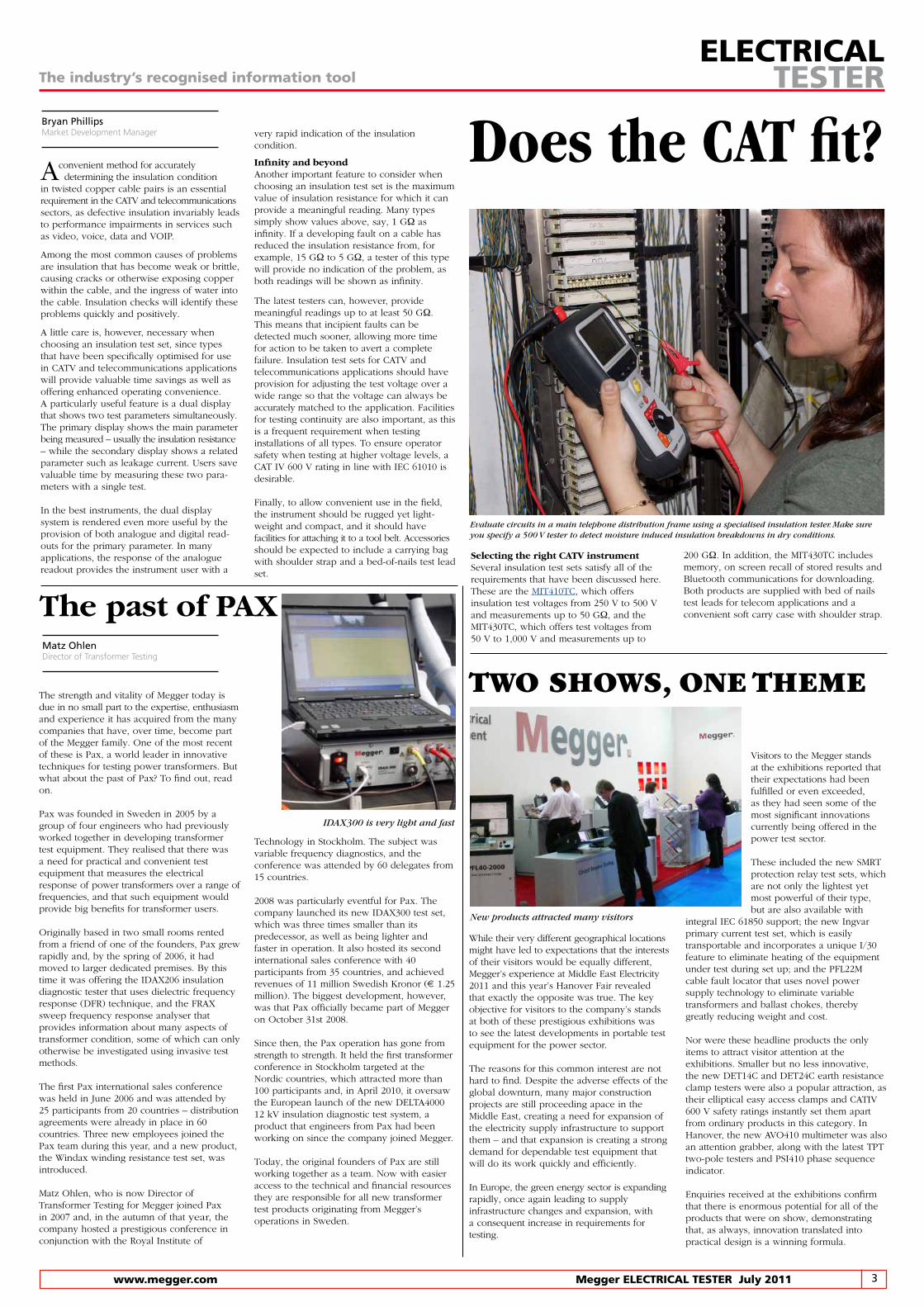
IDAX300 is very light and fast
200 GΩ. In addition, the MIT430TC includes memory, on screen recall of stored results and Bluetooth communications for downloading. Both products are supplied with bed of nails test leads for telecom applications and a convenient soft carry case with shoulder strap.
Technology in Stockholm. The subject was variable frequency diagnostics, and the conference was attended by 60 delegates from 15 countries.
2008 was particularly eventful for Pax. The company launched its new IDAX300 test set, which was three times smaller than its predecessor, as well as being lighter and faster in operation. It also hosted its second international sales conference with 40participants from 35 countries, and achieved revenues of 11 million Swedish Kronor (€ 1.25 million). The biggest development, however, was that Pax officially became part of Megger on October 31st 2008.
Since then, the Pax operation has gone from strength to strength. It held the first transformer conference in Stockholm targeted at the Nordic countries, which attracted more than 100 participants and, in April 2010, it oversaw the European launch of the new DELTA4000 12 kV insulation diagnostic test system, a product that engineers from Pax had been working on since the company joined Megger.
Today, the original founders of Pax are still working together as a team. Now with easier access to the technical and financial resources they are responsible for all new transformer test products originating from Megger’s operations in Sweden.
Evaluate circuits in a main telephone distribution frame using a specialised insulation tester. Make sure you specify a 500 V tester to detect moisture induced insulation breakdowns in dry conditions.
New products attracted many visitors
4 MeggerELECTRICALTESTERJuly2011 www.megger.com
instrument’s current capability is that it will impact its ability to maintain the selected test voltage when it needs to supply high surface-leakage currents.
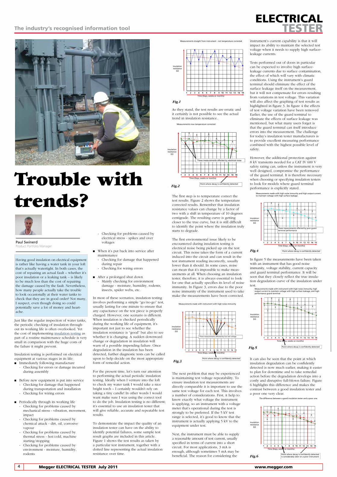
Tests performed out of doors in particular can be expected to involve high surface- leakage currents due to surface contamination, the effect of which will vary with climatic conditions. Using the instrument’s guard terminal should eliminate the effect of the surface leakage itself on the measurement, but it will not compensate for errors resulting from variations in test voltage. This variation will also affect the graphing of test results as highlighted in figure 3. In figure 4 the effects of test voltage variation have been removedEarlier, the use of the guard terminal to eliminate the effects of surface leakage was mentioned, but what many users forget is that the guard terminal can itself introduce errors into the measurement. The challenge for today’s insulation tester manufacturers is to provide excellent measuring performance combined with the highest possible level of safety.
However, the additional protection against 8 kV transients needed for a CAT IV 600 V safety rating can, unless the instrument is very well designed, compromise the performance of the guard terminal. It is therefore necessary when choosing or specifying insulation testers to look for models where guard terminal performance is explicitly stated.
In figure 5 the measurements have been taken with an instrument that has good noise immunity, voltage stability, current capacity and guard terminal performance. It will be seen that they closely reflect the true insula-tion degradation curve of the insulation under test.
It can also be seen that the point at which insulation degradation can be confidently detected is now much earlier, making it easier to plan for downtime and to take remedial action before the degradation develops into a costly and disruptive full-blown failure. Figure 6 highlights this difference and makes the contrast between a good insulation tester and a poor one very clear.
As they stand, the test results are erratic and it certainly is not possible to see the actual trend in insulation resistance.
The first step is to temperature correct the test results. Figure 2 shows the temperature corrected results. Remember that insulation resistance values can change by a factor of two with a shift in temperature of 10 degrees centigrade. The resulting curve is getting closer to the true curve, but it is still difficult to identify the point where the insulation truly starts to degrade.
The first environmental issue likely to be encountered during insulation testing is electrical noise being picked up on the test circuit. This noise takes the form of a current induced into the circuit and can result in the test instrument reading incorrectly, usually lower than it should. In some cases, noise can mean that it’s impossible to make meas-urements at all. When choosing an insulation tester, therefore, it is always essential to look for one that actually specifies its level of noise immunity. In Figure 3, errors due to the poor noise immunity of the instrument used to take make the measurements have been corrected.
The next problem that may be experienced is maintaining test voltage repeatability. To ensure insulation test measurements are directly comparable it is important to use the same test voltage for each test. This involves a number of considerations. First, it help to know exactly what voltage the instrument is applying, so an instrument with a voltage meter that’s operational during the test is strongly to be preferred. If the 5 kV test range is selected, it’s good to know that the instrument is actually applying 5 kV to the equipment under test.
Next, the instrument must be able to supply a reasonable amount of test current, usually specified in terms of current into a short circuit. For most applications, 3 mA is enough, although sometimes 5 mA may be beneficial. The reason for considering the
The industry’s recognised information toolELECTRICAL
TESTER
Paul SwinerdProduct Portfolio Manager
Trouble with trends?
Having good insulation on electrical equipment is rather like having a water tank in your loft that’s actually watertight. In both cases, the cost of repairing an actual fault – whether it’s poor insulation or a leaking tank – is likely to be much less than the cost of repairing the damage caused by the fault. Nevertheless, how many people actually take the trouble to look occasionally at their water tanks to check that they are in good order? Not many, I suspect, even though doing so could potentially save a lot of money and heart-ache.
Just like the regular inspection of water tanks, the periodic checking of insulation through-out its working life is often overlooked. Yet the cost of implementing insulation testing as part of a routine maintenance schedule is very small in comparison with the huge costs of the failure it might prevent.
Insulation testing is performed on electrical equipment at various stages in its life:n Immediately following manufacture - Checking for errors or damage incurred during assembly
n Before new equipment is put into service - Checking for damage that happened during transportation and installation - Checking for wiring errors
n Periodically through its working life - Checking for problems caused by mechanical stress - vibration, movement, impact - Checking for problems caused by chemical attack - dirt, oil, corrosive vapour - Checking for problems caused by thermal stress - hot/cold, machine starting/stopping - Checking for problems caused by environment - moisture, humidity, rodents
- Checking for problems caused by electrical stress - spikes and over voltages
n When it’s put back into service after maintenance - Checking for damage that happened during repair - Checking for wiring errors
n After a prolonged shut down - Mainly checking for environment damage - moisture, humidity, rodents, insects, spider webs, etc.
In most of these scenarios, insulation testing involves performing a simple “go/no-go” test, usually lasting for one minute to ensure that any capacitance on the test piece is properly charged. However, one scenario is different. When insulation is checked periodically during the working life of equipment, it’s important not just to see whether the insulation resistance is “good” but also to see whether it is changing. A sudden downward change or degradation in insulation will warn of a possible impending failure. Once degradation in the insulation has been detected, further diagnostic tests can be called upon to help decide on the most appropriate form of remedial action.
For the present time, let’s turn our attention to performing the actual periodic insulation testing. Ideally when I venture into the loft to check my water tank I would take a nice bright torch – I certainly wouldn’t rely on taking a tiny candle! In other words I would want make sure I was using the correct tool to do the job. Insulation testing is no different; it’s essential to use an insulation tester that will give reliable, accurate and repeatable test results.
To demonstrate the impact the quality of an insulation tester can have on the ability to identify potential failures, some sample test result graphs are included in this article.Figure 1 shows the test results as taken by a particular test instrument, together with a dotted line representing the actual insulation resistance over time.
Fig.1
Measurements straight from instrument - not temperature corrected
Time (Days, weeks or months)
Insulationresistance
(Ω)
These measurements affected by electrical noise
Fig.2
Measurements now temperature corrected
Insulationresistance
(Ω)
Time (Days, weeks or months)
Point where decay is confidently detected
Fig.6
Insulationresistance
(Ω)
Point where decay is confidently detected is considerably later on a poor instrument
Time (Days, weeks or months)
The difference between a good insulation tester and a poor one
Fig.5
Insulationresistance
(Ω)
Point where decay is confidently detected
Time (Days, weeks or months)
Measurements made with instrument with high noise immunity, high output current to maintain voltage with high surface leakage, and high performance guard terminal
These measurements affected by poor guard terminal performance
Fig.4
Measurements made with high noise immunity and high output current to maintain voltage with high surface leakage
Point where decay is confidently detected
Time (Days, weeks or months)
Insulationresistance
(Ω)
Fig.3
Insulationresistance
(Ω)
Time (Days, weeks or months)
Point where decay is confidently detected
Measurements made with instrument with high noise immunity
These measurements affected by low test voltage
5 www.megger.com MeggerELECTRICALTESTERJuly2011
The industry’s recognised information toolELECTRICAL
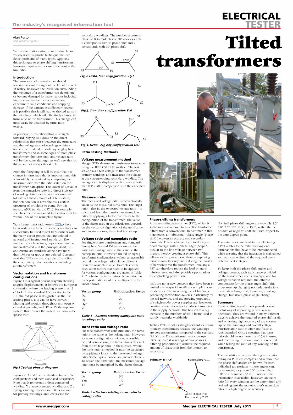
TESTERsecondary windings. The number represents phase shift in multiples of 30º – for example 0 corresponds with 0º phase shift and 2 corresponds with 60º phase shift.
RatioTestingMethods
VoltagemeasurementmethodMegger TTRs determine transformer turns ratio using the IEEE C57.12.90 method. The test set applies a test voltage to the transformer primary windings and measures the voltage at the corresponding secondary winding. The voltage ratio is displayed with accuracy better than 0.1%, after comparison with the expected ratio.
MeasuredratioThe measured voltage ratio is conventionally taken as the measured turns ratio. The target ratio – that is, the expected voltage ratio – is calculated from the transformer nameplate ratio by applying a factor that relates to the configuration of the transformer. The value of the factor used in the calculation depends on the vector configuration of the transformer and, in some cases, the actual test set up.
VoltageratioandnameplateratioFor single-phase transformers and standard three-phase Yy and Dd transformers, the turns ratio/voltage ratio is the same as the nameplate ratio. However, for Yd or zigzag transformer configurations without an accessible neutral, the voltage ratio will be different from the nameplate ratio. Examples of the calculation factors that need to be applied for various configurations are given in Table 1. To obtain the turns ratio/voltage ratio, the nameplate ratio should be multiplied by the factor shown.
Vector group Multiplication Factor Dd 1Dy √3Dyn √3Yd √3/2
Table 1 – Factors relating nameplate ratio to voltage ratio
TurnsratioandvoltageratioFor most transformer configurations, the turns ratio is the same as the voltage ratio. However, for some configurations without accessible neutral connections, the turns ratio is different from the voltage ratio. In these cases, where the turns ratio is needed, it must be calculated by applying a factor to the measured voltage ratio. Some typical factors are given in Table 2. To obtain the turns ratio, the measured voltage ratio must be multiplied by the factor shown.
Vector group Multiplication FactorDz 3/2Yzn 1/2Yd 2/3
Table 2 – Factors relating turns ratio to voltage ratio
Nominal phase shift angles are typically 2.5º, 5.0º, 7.5º, 10º, 12.5º, or 15.0º, with either a positive or negative shift (tilt) with respect to the zero degree point.
The extra work involved in manufacturing a PST relates to the extra winding end terminations that have to be interconnected while ensuring that the insulation is maintained so that it can withstand the required over-potential test voltages.
To keep both the phase shift angles and voltages correct, each tap change provided on the transformer needs two taps, one for voltage variation required, the other to compensate for the phase angle shift. This is because tap changing not only results in a turns ratio change and, therefore, a voltage change, but also a phase angle change.
SummaryPhase shifting transformers provide a very useful way of improving power system operation. They are wound in many different ways to achieve the required phase shift or tilt, and achieving high accuracy of the chosen tap on the windings and overall voltage transformation ratio is often not feasible. ANSI Standard C57.12 specifies that turns ratio should be no more than 0.5% in error, and that this figure should not be exceeded when testing the ratio of any winding on the transformer.
The calculations involved during turns ratio testing on PSTs are complex and require that the phase shift angles are known for each individual tap position – these angles can, for example, vary from 6.5º to more than 9.0º on a nominal 7.5º PST. Provided this information is available, however, an exact ratio for every winding can be determined and verified against the manufacturer’s nameplate ratio to a high degree of accuracy.
Alan PurtonApplications Engineer
Transformer ratio testing is an invaluable and widely used diagnostic technique that can detect problems of many types. Applying this technique to phase-shifting transformers, however, requires extra care to determine the true ratio.
IntroductionThe turns ratio of a transformer should remain constant throughout the life of the unit. In reality, however, the insulation surrounding the windings of a transformer can deteriorate or become damaged for many reasons including high voltage transients, contamination, exposure to fault conditions and shipping damage. If the damage is sufficiently severe,it is possible that it will lead to shorted turns in the windings, which will effectively change the turns ratio of the transformer. This change can most easily be detected by turns ratio testing.
In principle, turns ratio testing is straight-forward, relying as it does on the direct relationship that exists between the turns ratio and the voltage ratio of windings within a transformer. Indeed, in ordinary single-phase transformers and in some types of three-phase transformer, the turns ratio and voltage ratio will be the same although, as we’ll see shortly, things are not always this simple.
From the foregoing, it will be clear that it is change in turns ratio that is important and this is invariably determined by comparing the measured ratio with the ratio stated on the transformer nameplate. The extent of deviation from the nameplate ratio is a direct indicator of winding deterioration. A transformer will tolerate a limited amount of deterioration, but deterioration is nevertheless a certain precursor of problems to come. For this reason, ANSI Standard C57.12, for example, specifies that the measured turns ratio must be within 0.5% of the nameplate figure.
Transformer turns ratio testers (TTRs) have been widely available for some years, they can successfully be used to test transformers with the many vector groups that are defined in national and international standards. The number of such vector groups should not be underestimated – in the principal ANSI, IEC and Australian standards alone have more than 130 vector groups are defined. Currently available TTRs are also capable of handling these and many other variations, including autotransformers.
VectornotationandtransformerconfigurationsFigure 1 is a typical phasor diagram showing angular displacements. It follows the European convention where the leading phase is at 12 o’clock. In the standard HV practice in the UK, the red phase is designated as the HV leading phase. It is vital to have correct phasing and rotation throughout any open or closed ring-configured HV or LV three-phase system, this ensures the system will always be ‘phase true’.
Figures 2, 3 and 4 show standard transformer configurations and there associated designations. Note that D represents a delta-connected winding, Y a star-connected winding and Z a zigzag winding. Upper case letters are used for primary windings, and lower case for
Phase-shiftingtransformersA phase-shifting transformer (PST), which is sometimes also referred to as a tilted transformer, differs from a conventional transformer in that it generates an “abnormal” phase angle (phase shift) between its primary and secondary terminals. This is achieved by introducing a boost voltage with a phase angle perpen-dicular to the line voltage between two phases, thereby creating a phase shift. This influences real power flow, thereby improvingtransmission efficiency and reducing the transfer of harmonics via the transformer. Installing a PST can therefore reduce the load on trans-mission lines, and also provide opportunities for controlling power flow.
PSTs are not a new concept; they have been in limited use in special rectification applications for decades. The increasing use of harmonic generating rectification systems, particularly by the rail network, and the growing popularity of switch-mode power supplies are, however, creating a need for ways to reduce harmonics in the supply network. This has led to a big increase in the numbers of PSTs being used in supply networks worldwide.
Testing PSTs is not as straightforward as testing ordinary transformers because the windings are very asymmetrical compared to the standard Dd, Yy and Dz transformer vector groups. PSTs use partial windings of two phases in differing proportions to achieve the required amount of phase shift from the primary to secondary.
P 1
P 2 S3
S1
S2
S2
120º
60º
P3
P1
P2 S3
S1
S2
30º
Angle shifted fromHorizontal by 7.5O
Primary D+7.5 Secondary y11
Fig 4. Delta - Zig Zag configuration Dz1
Fig 2. Delta- Star configuration Dy1
Fig 3. Star- Star configuration Yy0
Tilted transformers
RED reference30 Lag
YELLOWBLUE
330 Lag
60
90
Fig.1 Typical phasor diagram
6 MeggerELECTRICALTESTERJuly2011 www.megger.com
The industry’s recognised information toolELECTRICAL
TESTER
High velocity STATES®
High Velocity Helper LLC, a firm dedicated to assisting homeowners and HVAC installers to realise the superior performance available from small duct high velocity air distribution systems, are currently working on a rescue project involving a historic 1850s-era five-story brownstone residence in Manhattan. Robert Yaciuk, CEO of High Velocity Helper explains “It has taken over two years to complete because the remedial work had to be done in a precise manner that would not damage the historic interior architecture and the home’s literally irreplaceable tiger oak woodwork.”“The work is complex and has involved extensive modifications to a system that was incorrectly designed and installed. Our objective is not just to leave the system in good working order when the project is finished, but also to make sure that it can easily be maintained in good order in the future.”
It is in this area of ongoing maintenance that the STATES (a division of Megger) FMS switches play a key role. Originally developed for use in electricity substations and other areas of utility transmission and distribution
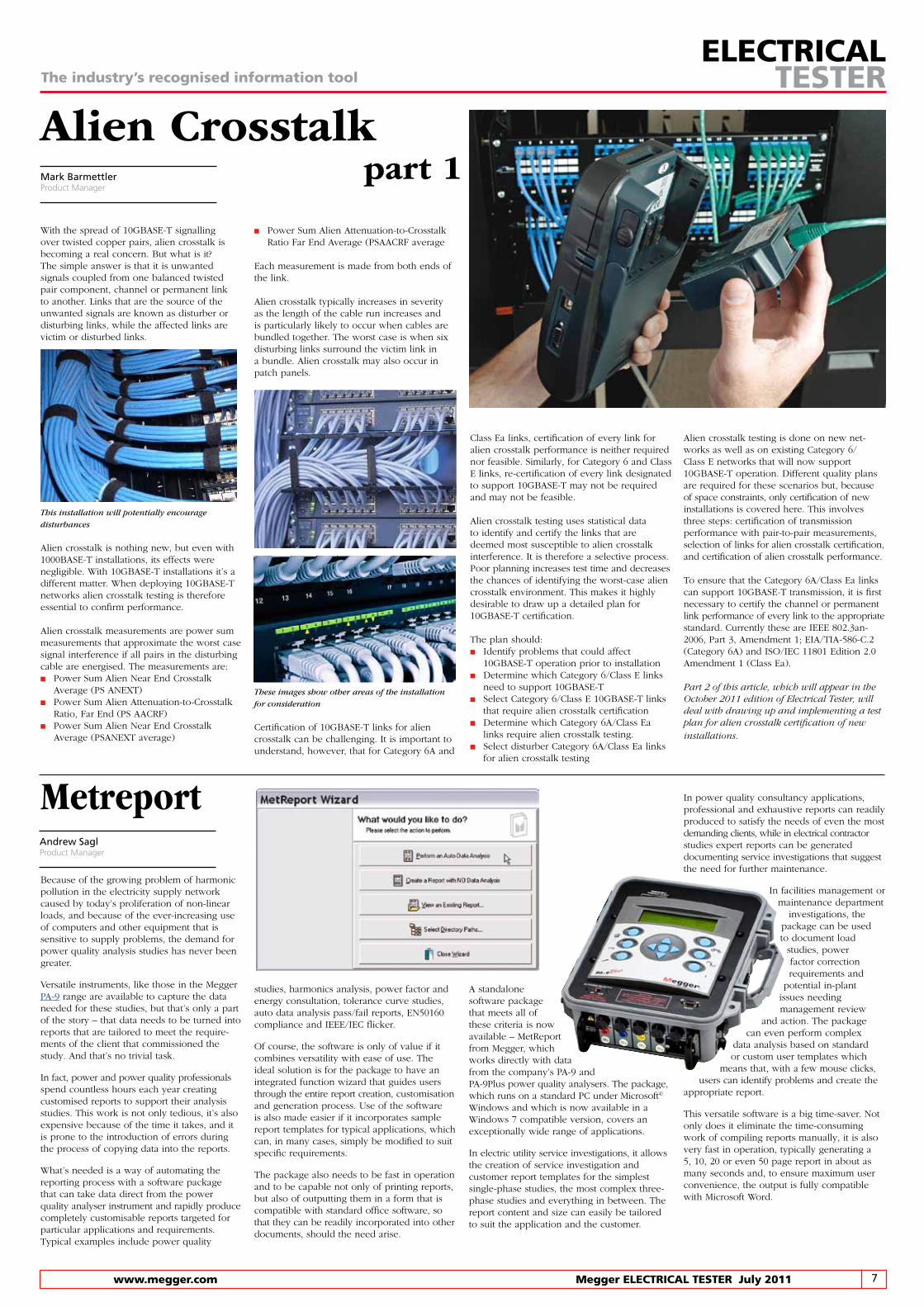
FMS Test Switches used in enclosure
FIT CLUB FOR TRANSFORMERS!Dramatic increases in the cost of raw materials have sent the price of new power transformers soaring, yet global demand is such that deliveries are often quoted in months or even years. As a result, there is a growing interest in services that will extend the life and increase reliability of existing transformers. And those services are exactly what Alstom Grid’s Service Business has been set up to provide.
In 2005, the price of copper on world markets was less than $4,000 per tonne. Now, the end of 2010, that price has risen to $9,000 per tonne. There is a lot of copper in a power transformer – not to mention transformer steel, which has also seen large price increases – so it is inevitable that the price of transformers has also risen steeply. The result is that budgets for replacing ageing transformers, which looked perfectly reasonable and adequate just a few years ago now fall woefully short of the mark.
For this reason, utilities and other users of power transformers are being forced into a position where their only option is to delay replacement as long as possible, even though this means, in many cases, keeping transformers in service that have long passed the end of their design life. This course of action is not without its problems. In particular, it leads to an increased risk of in-service transformer failures.
Such failures are potentially disruptive and costly, not only for utility companies that face revenue penalties if they fail to meet targets for consumer minutes lost set by Government regulators, but also for industrial organisations where an out-of-service plant can easily result in massive production losses. And, when a power transformer fails, difficulties in finding the money for a replacement are only part of the problem.
Because of the strong and growing demand for power transformers from the emerging economies, there is a world shortage of manufacturing capacity, which means that delivery times of many months are typical and, particularly for the largest types, delivery times well in excess of a year are by no mean unusual. In other words, if a transformer fails, its owner not only faces a huge chunk of un-planned expenditure, they may well also have to wait a very long time before a replacement arrives and their operations can be returned to normal.
What’s to be done? The answer is to look after in-service transformers very carefully so as to extend their lives and minimise the risk of failure and, if the worst happens and a transformer does fail, to investigate fully the possibility of repairing rather than replacing it.
All of this falls within the scope of Alstom Grid’s new Service Business, which has recently started operations from fully refurbished and comprehensively equipped premises in Stafford England. These new premises are adjacent to Alstom Grid’s main power transformer factory, which is now the UK’s largest manufacturing plants for power transformers.
Alstom Grid’s Service Business is Northern Europe’s largest transformer service provider and has a dedicated site team of 29 skilled employees with a wealth of transformer and tap changer experience. The business’s new premises in Stafford England include a 2000 m2 workshop, adding up to the 3,000 m2 service workshop, with 120 tonne, 30 tonne and 20 tonne cranes, vertical and horizontal winding machines, a vacuum process oven, silicone process plant, HV test module and oil laboratory. Transformers in the voltage range 3.3 – 132 kV with ratings up to 100 MVA can be handled. Larger units can be considered on
a bespoke project basis. Services available include condition assessment, fault investigation, manufacture of replacement windings, core refurbishment, oven processing, re-design and re-manufacture, general refurbishment, modernisation and extension with comprehensive HV testing.
While these facilities and services repair damaged transformers, much of the Service Business’s work ensures that transformers deliver the highest possible level of in-service reliability, with the minimum risk of failure. The key to achieve these objectives is regular condition assessment, together with carefully planned and properly implemented routine maintenance. “We can, of course, provide all of these services for our clients,” said Philip Inskip, Business Manager for Alstom Grid’s Transformer Services Business, “but there is one small snag – power transformers are not exactly portable. It’s one thing to bring a transformer to our premises for major refurbishment or repair – and, indeed we have special transport systems in place for doing just that – but it’s hardly convenient to bring a transformer in for routine assessment and maintenance. For this type of work, we take our services to the transformer.”
This is made possible by the mobile nature of the new equipment the Service Business has at its disposal. Firstly they have a mobile test facility that has been designed to fit into a 13 meter container. Based on the latest static frequency technology, this module can be transported to site anywhere in the UK or Europe and has the capability of performing a wide range of HV tests including partial discharge measurements. This system is supported by a wide range of portable diagnostic equipment enabling Alstom Grid’s - Transformer Service to comprehensively assess the condition of a transformer or to identify a suspected fault.
Secondly the Oil Process Plant is equipped for vacuum processing of transformer oil in addition to moisture removal, degassing and filtering. It incorporates oil regeneration columns, acid and sludge removal facilities, and can treat oil to minimise the effects of corrosive sulphur. It even has its own generator set to allow completely standalone operation when no external power source is available. As would be expected, testing is an important part of the vehicle’s operations and, because of this, it has a well-equipped on-board oil testing laboratory.
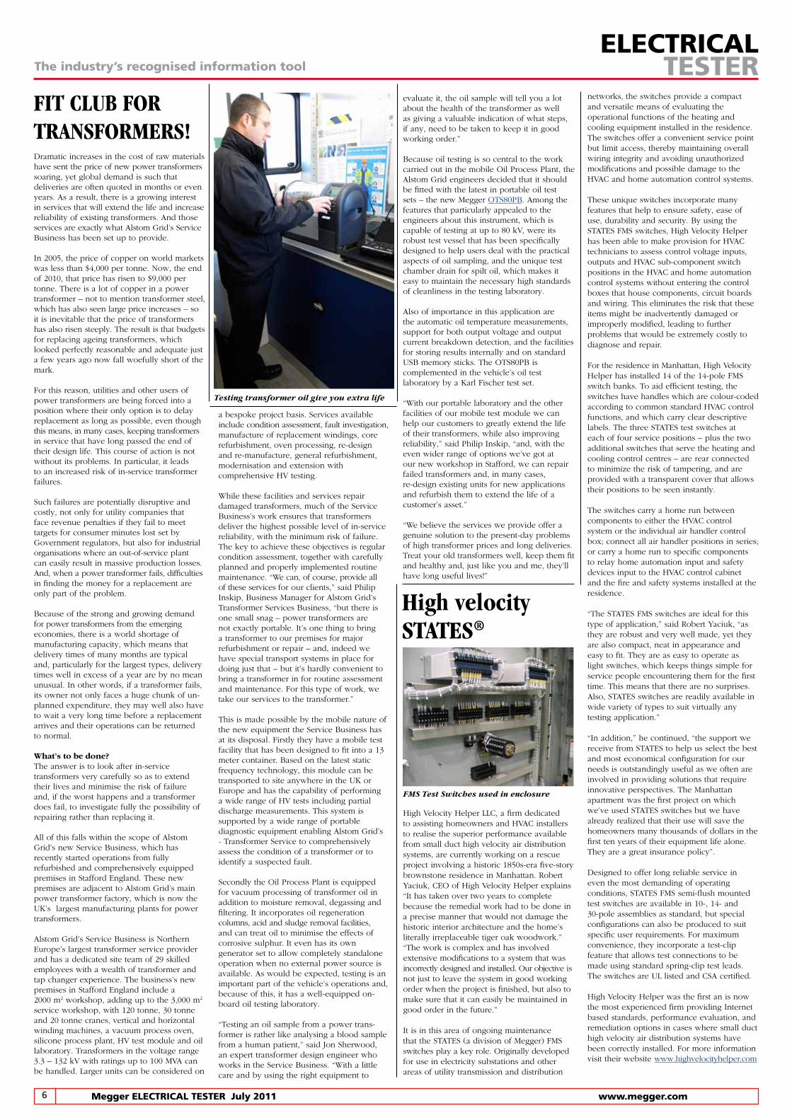
“Testing an oil sample from a power trans-former is rather like analysing a blood sample from a human patient,” said Jon Sherwood, an expert transformer design engineer who works in the Service Business. “With a little care and by using the right equipment to
evaluate it, the oil sample will tell you a lot about the health of the transformer as well as giving a valuable indication of what steps, if any, need to be taken to keep it in good working order.”
Because oil testing is so central to the work carried out in the mobile Oil Process Plant, the Alstom Grid engineers decided that it should be fitted with the latest in portable oil test sets – the new Megger OTS80PB. Among the features that particularly appealed to the engineers about this instrument, which is capable of testing at up to 80 kV, were its robust test vessel that has been specifically designed to help users deal with the practical aspects of oil sampling, and the unique test chamber drain for spilt oil, which makes it easy to maintain the necessary high standards of cleanliness in the testing laboratory.
Also of importance in this application are the automatic oil temperature measurements, support for both output voltage and output current breakdown detection, and the facilities for storing results internally and on standard USB memory sticks. The OTS80PB is complemented in the vehicle’s oil test laboratory by a Karl Fischer test set.
“With our portable laboratory and the other facilities of our mobile test module we can help our customers to greatly extend the life of their transformers, while also improving reliability,” said Philip Inskip, “and, with the even wider range of options we’ve got at our new workshop in Stafford, we can repair failed transformers and, in many cases, re-design existing units for new applications and refurbish them to extend the life of a customer’s asset.”
“We believe the services we provide offer a genuine solution to the present-day problems of high transformer prices and long deliveries. Treat your old transformers well, keep them fit and healthy and, just like you and me, they’ll have long useful lives!”
networks, the switches provide a compact and versatile means of evaluating the operational functions of the heating and cooling equipment installed in the residence. The switches offer a convenient service point but limit access, thereby maintaining overall wiring integrity and avoiding unauthorized modifications and possible damage to the HVAC and home automation control systems.
These unique switches incorporate many features that help to ensure safety, ease of use, durability and security. By using the STATES FMS switches, High Velocity Helper has been able to make provision for HVAC technicians to assess control voltage inputs, outputs and HVAC sub-component switch positions in the HVAC and home automation control systems without entering the control boxes that house components, circuit boards and wiring. This eliminates the risk that these items might be inadvertently damaged or improperly modified, leading to further problems that would be extremely costly to diagnose and repair.
For the residence in Manhattan, High Velocity Helper has installed 14 of the 14-pole FMS switch banks. To aid efficient testing, the switches have handles which are colour-coded according to common standard HVAC control functions, and which carry clear descriptive labels. The three STATES test switches at each of four service positions – plus the two additional switches that serve the heating and cooling control centres – are rear connected to minimize the risk of tampering, and are provided with a transparent cover that allows their positions to be seen instantly.
The switches carry a home run between components to either the HVAC control system or the individual air handler control box; connect all air handler positions in series; or carry a home run to specific components to relay home automation input and safety devices input to the HVAC control cabinet and the fire and safety systems installed at the residence.
“The STATES FMS switches are ideal for this type of application,” said Robert Yaciuk, “as they are robust and very well made, yet they are also compact, neat in appearance and easy to fit. They are as easy to operate as light switches, which keeps things simple for service people encountering them for the first time. This means that there are no surprises. Also, STATES switches are readily available in wide variety of types to suit virtually any testing application.”
“In addition,” he continued, “the support we receive from STATES to help us select the best and most economical configuration for our needs is outstandingly useful as we often are involved in providing solutions that require innovative perspectives. The Manhattan apartment was the first project on which we’ve used STATES switches but we have already realized that their use will save the homeowners many thousands of dollars in the first ten years of their equipment life alone. They are a great insurance policy”.
Designed to offer long reliable service in even the most demanding of operating conditions, STATES FMS semi-flush mounted test switches are available in 10-, 14- and 30-pole assemblies as standard, but special configurations can also be produced to suit specific user requirements. For maximum convenience, they incorporate a test-clip feature that allows test connections to be made using standard spring-clip test leads. The switches are UL listed and CSA certified.
High Velocity Helper was the first an is now the most experienced firm providing Internet based standards, performance evaluation, and remediation options in cases where small duct high velocity air distribution systems have been correctly installed. For more information visit their website www.highvelocityhelper.com
Testing transformer oil give you extra life
7 www.megger.com MeggerELECTRICALTESTERJuly2011
The industry’s recognised information toolELECTRICAL
TESTER
Mark BarmettlerProduct Manager
Alien Crosstalk part 1
Metreport
With the spread of 10GBASE-T signalling over twisted copper pairs, alien crosstalk is becoming a real concern. But what is it? The simple answer is that it is unwanted signals coupled from one balanced twisted pair component, channel or permanent link to another. Links that are the source of the unwanted signals are known as disturber or disturbing links, while the affected links are victim or disturbed links.
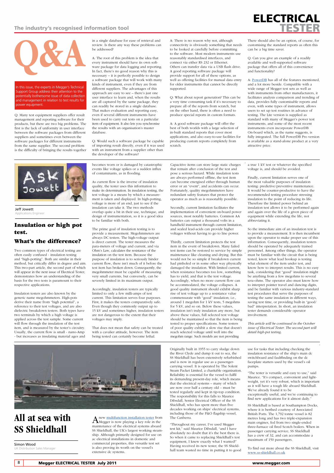
This installation will potentially encourage
disturbances
Alien crosstalk is nothing new, but even with 1000BASE-T installations, its effects were negligible. With 10GBASE-T installations it’s a different matter. When deploying 10GBASE-T networks alien crosstalk testing is therefore essential to confirm performance. Alien crosstalk measurements are power sum measurements that approximate the worst case signal interference if all pairs in the disturbing cable are energised. The measurements are:n Power Sum Alien Near End Crosstalk Average (PS ANEXT)n Power Sum Alien Attenuation-to-Crosstalk Ratio, Far End (PS AACRF)n Power Sum Alien Near End Crosstalk Average (PSANEXT average)
n Power Sum Alien Attenuation-to-Crosstalk Ratio Far End Average (PSAACRF average
Each measurement is made from both ends of the link.
Alien crosstalk typically increases in severity as the length of the cable run increases and is particularly likely to occur when cables are bundled together. The worst case is when six disturbing links surround the victim link in a bundle. Alien crosstalk may also occur in patch panels.
These images show other areas of the installation
for consideration
Certification of 10GBASE-T links for alien crosstalk can be challenging. It is important to understand, however, that for Category 6A and
Because of the growing problem of harmonic pollution in the electricity supply network caused by today’s proliferation of non-linear loads, and because of the ever-increasing use of computers and other equipment that is sensitive to supply problems, the demand for power quality analysis studies has never been greater.
Versatile instruments, like those in the Megger PA-9 range are available to capture the data needed for these studies, but that’s only a part of the story – that data needs to be turned into reports that are tailored to meet the require-ments of the client that commissioned the study. And that’s no trivial task.
In fact, power and power quality professionals spend countless hours each year creating customised reports to support their analysis studies. This work is not only tedious, it’s also expensive because of the time it takes, and it is prone to the introduction of errors during the process of copying data into the reports.
What’s needed is a way of automating the reporting process with a software package that can take data direct from the power quality analyser instrument and rapidly produce completely customisable reports targeted for particular applications and requirements. Typical examples include power quality
studies, harmonics analysis, power factor and energy consultation, tolerance curve studies, auto data analysis pass/fail reports, EN50160 compliance and IEEE/IEC flicker.
Of course, the software is only of value if it combines versatility with ease of use. The ideal solution is for the package to have an integrated function wizard that guides users through the entire report creation, customisation and generation process. Use of the software is also made easier if it incorporates sample report templates for typical applications, which can, in many cases, simply be modified to suit specific requirements.
The package also needs to be fast in operation and to be capable not only of printing reports, but also of outputting them in a form that is compatible with standard office software, so that they can be readily incorporated into other documents, should the need arise.
A standalone software package that meets all of these criteria is now available – MetReport from Megger, which works directly with data from the company’s PA-9 and PA-9Plus power quality analysers. The package, which runs on a standard PC under Microsoft© Windows and which is now available in a Windows 7 compatible version, covers an exceptionally wide range of applications.
In electric utility service investigations, it allows the creation of service investigation and customer report templates for the simplest single-phase studies, the most complex three-phase studies and everything in between. The report content and size can easily be tailored to suit the application and the customer.
Class Ea links, certification of every link for alien crosstalk performance is neither required nor feasible. Similarly, for Category 6 and Class E links, re-certification of every link designated to support 10GBASE-T may not be required and may not be feasible.
Alien crosstalk testing uses statistical data to identify and certify the links that are deemed most susceptible to alien crosstalk interference. It is therefore a selective process. Poor planning increases test time and decreases the chances of identifying the worst-case aliencrosstalk environment. This makes it highly desirable to draw up a detailed plan for 10GBASE-T certification.
The plan should: n Identify problems that could affect 10GBASE-T operation prior to installationn Determine which Category 6/Class E links need to support 10GBASE-Tn Select Category 6/Class E 10GBASE-T links that require alien crosstalk certificationn Determine which Category 6A/Class Ea links require alien crosstalk testing.n Select disturber Category 6A/Class Ea links for alien crosstalk testing
Andrew SaglProduct Manager
Alien crosstalk testing is done on new net-works as well as on existing Category 6/Class E networks that will now support 10GBASE-T operation. Different quality plans are required for these scenarios but, because of space constraints, only certification of new installations is covered here. This involves three steps: certification of transmission performance with pair-to-pair measurements, selection of links for alien crosstalk certification, and certification of alien crosstalk performance.
To ensure that the Category 6A/Class Ea links can support 10GBASE-T transmission, it is first necessary to certify the channel or permanent link performance of every link to the appropriate standard. Currently these are IEEE 802.3an-2006, Part 3, Amendment 1; EIA/TIA-586-C.2 (Category 6A) and ISO/IEC 11801 Edition 2.0 Amendment 1 (Class Ea).
Part 2 of this article, which will appear in the October 2011 edition of Electrical Tester, will deal with drawing up and implementing a test plan for alien crosstalk certification of new installations.
In power quality consultancy applications, professional and exhaustive reports can readily produced to satisfy the needs of even the most demanding clients, while in electrical contractor studies expert reports can be generated documenting service investigations that suggest the need for further maintenance.
In facilities management or maintenance department investigations, the package can be used to document load
studies, power factor correction requirements and
potential in-plant issues needing
management review and action. The package
can even perform complex data analysis based on standard or custom user templates which
means that, with a few mouse clicks, users can identify problems and create the
appropriate report.
This versatile software is a big time-saver. Not only does it eliminate the time-consuming work of compiling reports manually, it is also very fast in operation, typically generating a 5, 10, 20 or even 50 page report in about as many seconds and, to ensure maximum user convenience, the output is fully compatible with Microsoft Word.
8 MeggerELECTRICALTESTERJuly2011 www.megger.com
Q&AIn this issue, the experts in Megger’s Technical Support Group address their attention to the potentially bothersome issue of data collection and management in relation to test results for power equipment.
Q: Many test equipment suppliers offer result management and reporting software for their products, but there are two big problems. The first is the lack of uniformity in user interface between the software packages from different suppliers and sometimes even between the software packages for different instruments from the same supplier. The second problem is the difficulty of bringing the results together
in a single database for ease of retrieval and review. Is there any way these problems can be addressed?
A: The root of this problem is the idea that every instrument should have its own soft-ware package for data logging and reporting. In fact, there’s no good reason why this is necessary – it is perfectly possible to design a software package that will work with many kinds of instrument, even if they are from different suppliers. The advantages of this approach are easy to see – there’s just one user interface to learn and, when the results are all captured by the same package, they can readily be stored in a single database. That makes evaluation and reporting easy, even if several different instruments have been used to carry out tests on a particular item of equipment. It also lets you synchronise the results with an organisation’s master database.
Q: Would such a software package be capable of importing result directly, even if it was used with an instrument from a supplier other than the developer of the software?
A: There is no reason why not, although connectivity is obviously something that needs to be looked at carefully before committing to the software. Most modern instruments use reasonably standardised interfaces, and connect via either RS 232 or Ethernet. Others can transfer data via a USB flash drive. A good reporting software package will provide support for all of these options, as well as offering facilities for manual data entry for older instruments that cannot be directly supported.
Q: What about report generation? This can be a very time consuming task if it’s necessary to prepare all of the reports from scratch, but on the other hand, there is often a need to produce special reports in custom formats.
A: A good software package will offer the best of both worlds with a large selection of in-built standard reports that cover most applications, and also easy-to-use facilities for producing custom reports completely from scratch.
Jeff JowettApplications Engineer
The industry’s recognised information toolELECTRICAL
TESTER
All at sea with SS Shieldhall
A new multifunction installation tester from Megger is now playing a key role in the
maintenance of the electrical systems aboard SS Shieldhall, the UK’s largest working steam-ship. Although primarily designed for use on ac electrical installations in domestic and commercial properties, this versatile test set is also proving its worth on the vessel’s extensive dc systems.
There should also be an option, of course, for customising the standard reports as often this can be a big time saver.
Q: Can you give an example of a readily available and well-supported software package that offers all of this convenience and functionality?
A: PowerDB has all of the features mentioned, and a lot more beside. Compatible with a wide range of Megger test sets as well as with instruments from other manufacturers, it facilitates analysis comparison and trending of data, provides fully customisable reports and even, with some types of instrument, allows users to set up test routines in advance of testing. The Lite version is supplied as standard with many of Megger’s power test instruments, and some of the most recent instruments even incorporate PowerDB On-board which, as the name suggests, is fully integrated. The full PowerDB Pro version is available as a stand-alone product at a very attractive price.
Originally built in 1955 to carry sludge down the River Clyde and dump it out to sea, the SS Shieldhall has been extensively refurbished and is now in regular use as a passenger-carrying vessel. It is operated by The Solent Steam Packet Limited, a charitable organisation.Reliability is essential for the vessel to fulfil its demanding present-day role, which means that the electrical systems – many of which are now over half a century old – must be tested regularly and kept in tip-top condition. The responsibility for this falls to Maurice Dibsdall, Senior Electrical Officer of the SS Shieldhall, who has spent more than five decades working on ships’ electrical systems, including those of the P&O flagship vessel, The Canberra.
“Throughout my career, I’ve used Megger test kit,” said Maurice Dibsdall, “and I have absolutely no doubt that it’s the best there is. So when it came to replacing Shieldhall’s test equipment, I knew exactly what I wanted!”Having received its new tester, the SS Shield-hall team wasted no time in putting it to good
Simon WoodUK Distribution Sales Manager
Insulation or high pot test.
What’s the difference?
Two common types of electrical testing are often easily confused - insulation testing and “high-potting”. Both are similar in their method, but critically differ in degree and aim. This two-part article, the second part of which will appear in the next issue of Electrical Tester, demonstrates how an understanding of the basis for the two tests is paramount to their respective applications.
Insulation testers are also known by the generic name megohmmeters. High-pots derive their name from “high potential”, a reference to their test voltages, and are also dielectric breakdown testers. Both types have two terminals by which a high voltage is applied across the test sample. Some current will flow through the insulation of the test item, and is measured by the tester’s circuitry. Usually, the current flow is small - nano-Amp - but increases as insulating material ages and
becomes worn or is damaged by catastrophic events like voltage spikes or a sudden influx of contaminants, as in flooding.
As current flow is the inverse of insulation quality, the tester uses this information to make its determination. In insulation testing, the test voltage is a means by which a measure-ment is taken and displayed. In high-potting, voltage is more of an end, just to see if the insulation can take it. The two methods overlap quite a bit in their use, technique, and design of instrumentation, so it is a good idea to be familiar with both.
The prime goal of insulation testing is to provide a measurement. Megohmmeters are always DC testers. The high-voltage output is direct current. The tester measures the para-meters of voltage and current, and via Ohm’s Law, calculates the resistance of the insulation on the test item. Because the purpose of insulation is to seriously hinder current flow, there isn’t much of it before the test item has broken down. Consequently, the megohmmeter must be capable of measuring very small currents, but conversely, can be severely limited in its maximum output.
Accordingly, insulation testers are typically limited to only a few milli-amps of test current. This limitation serves four purposes. First, it makes the testers comparatively safe. Even though they commonly output up to 15 kV and sometimes higher, insulation testers are not dangerous to the extent that their voltages may imply.
That does not mean that safety can be treated with a cavalier attitude, however. The item being tested can certainly become lethal.
Capacitive items can store large static charges that remain after conclusion of the test and pose a serious hazard. While insulation tests are always performed offline, the test item can become energised either through human error or an “event”, and accidents can occur. Fortunately, quality megohmmeters have redundant safety features that protect the operator as much as is reasonably possible.
Secondly, current limitation facilitates the implementation of convenient on-board power sources, most notably batteries. Common AA batteries can output a thousand volts in a handheld instrument through current limitation, and sealed lead-acids can provide higher voltages without having to go to line power.
Thirdly, current limitation protects the test item in the event of breakdown. Many failed test items can be restored to service by simple maintenance like cleaning and drying. But this would not be so simple if breakdown current had pinholed or in some other way physically damaged the insulation. With limited current, when resistance becomes too low, something has to yield, and that is the test voltage. Accordingly, when no more current flow can be accommodated, the voltage collapses. A good quality instrument should exhibit sharp rise of test voltage up to a resistance value commensurate with “good” insulation; i.e., around 1 megohm for 1 kV tests, 5 megohms for 5 kV, and so on. Below these values, insulation isn’t truly insulation any more, but above these values, full selected test voltage should be maintained so that the item is being tested to proper specifications. Some testers of poor quality exhibit a slow rise that doesn’t reach selected voltage until well into the megohm range. Such models are not providing
a true 1 kV test or whatever the specified voltage is, and should be avoided.
Finally, current limitation serves one of the most valuable purposes of insulation testing: predictive/preventive maintenance. It would be counter-productive to have the recommended testing procedure stressing insulation to the point of reducing its life. Therefore the limited power behind an insulation test allows it to be performed again and again over the life of a given piece of equipment while extending the life, not abbreviating it.
So the immediate aim of an insulation test is to provide a measurement. It is then incumbent upon the operator to make proper use of this information. Consequently, insulation testers should be operated by adequately trained personnel. Among other things, the operator must be familiar with the circuit that is being tested, know what lead hookup is testing what element of the item under test, and know how to interpret results. This is no easy task, considering that “good” insulation might be anything from a few megohms to several tera-ohms. The operator also must know how to interpret pointer travel and dancing digits, and be familiar with various industry-standard test procedures that serve the purposes of testing the same insulation in different ways, saving test time, or providing built-in “good/bad” interpretation. In short, an insulation tester demands considerable operator involvement.
This article will be continued in the October issue of Electrical Tester. The second part will detail high-pot testing.
use for tasks that including checking the insulation resistance of the ship’s main dc switchboard and faultfinding on the dc faceplate starters used by the vessel’s oil pumps.
“The tester is versatile and easy to use,” said Maurice. “It’s compact, convenient and light-weight, yet it’s very robust, which is important as it will have a tough life aboard Shieldhall. We’ve already found it to be exceptionally useful, and we’re continuing to find new applications for it almost daily.”
SS Shieldhall is based at Southampton Docks, where it is berthed courtesy of Associated British Ports. The 1,792 tonne vessel is 82 metres long and has two triple-expansion main engines, fed from two single-ended three-furnace oil fired Scotch boilers. When in passenger carrying service, SS Shieldhall has a crew of 32, and can accommodate a maximum of 150 passengers.
To find out more about the SS Shieldhall, visit www.ss-shieldhall.co.uk