Embed Size (px)
Citation preview

PTO Mini-CAFS Installation & Operation Manual
Model MCP50 with FoamLogix 2.1A System
HALE PRODUCTS EUROPE A Unit of IDEX Corporation Charles St Warwick CV34 5LR England +44 (0)1926 623600 +44 (0)1926 623666 [email protected] GP/212/05, Issue 6, July 2006.

1
Amendment Record for MCP50 with FoamLogix 2.1A System Number Date Page/s Amendment New Issue #
1 July 2005 7 Delete “Max. Foam solution flowrate” data Issue 4, July 2005 2 July 2005 13 1. Compressor 1.2 – change “700 L/min at 7.0
Bar” to “400 L/min at 7.0 Bar” Issue 4, July 2005
3 July 2005 1 (front) New photo of complete system Issue 4, July 2005 4 July 2005 15 1.4 The Safety Interlock system – change from
24V to 12-24V DC power supply Issue 4, July 2005
5 July 2005 31 Compressor Assembly drawing – reverse arrows indicating water flow through oil cooler, now left to right
Issue 4, July 2005
6 July 2006 28 Added ‘no air inject’ fault tree Issue 6, July 2006
©Hale Products Europe. Our policy is one of continuous development. We therefore reserve the right to amend specifications without notice or obligation.

2
INDEX SECTION PAGE IMPORTANT NOTES 3 SAFETY-RELEVANT DATA 4 ENVIRONMENTAL PROTECTION 5 GENERAL DATA 6 RECOMMENDED LUBRICANTS 6 MAJOR COMPONENTS AND CONTROLS 7-8 SYSTEM OPERATION 9-10 INSTALLATION 12 INSTALLATION AND INITIAL SET-UP 13-19 RECOMMENDED FOAM AGENTS 19 OPERATION 20 OPERATING THE SYSTEM 21
COMMISSIONING/START-UP PROCEDURE 22
OPERATING MCP50 FROM A VEHICLE WATER SOURCE 23 DISCHARGING WATER / FOAM AGENT MIXTURE 23 DISCHARGING CAFS 24 WET FOAM OR DRY FOAM 24 SHUTTING DOWN 24
OVERHEAT SHUT DOWN 25
MAINTENANCE SCHEDULE 26 FAULT FINDING 26 INSTALLATION DRAWINGS 28-36
©Hale Products Europe. Our policy is one of continuous development. We therefore reserve the right to amend specifications without notice or obligation.

3
IMPORTANT NOTES
Please read this manual before operating the equipment. Every care has been taken during the manufacture of this equipment to ensure that it leaves the factory capable of giving a long period of trouble-free running. Correct lubrication and maintenance is essential if satisfactory performance is to be maintained.
©Hale Products Europe. Our policy is one of continuous development. We therefore reserve the right to amend specifications without notice or obligation.

4
SAFETY - RELEVANT DATA Thank you for purchasing this equipment. This unit is designed to give safe and reliable service – however, BEFORE operation it is essential that the Operating Instructions are carefully read and understood. A risk-assessment of the equipment has been conducted with the following results: MAINTENANCE It is the responsibility of the user to ensure that the equipment is maintained in a safe operational condition, as per regulation 5 in the Provision and Use of Work Equipment Regulations 1998. TRAINING It is ESSENTIAL the equipment is operated ONLY by TRAINED PERSONNEL. Manufacturer’s training can be obtained on application to Hale Products Europe Ltd., Charles Street, Warwick CV34 5LR, England. Tel: +44 (0)1926 623600. To avoid injury, the operators should take all necessary precautions to safeguard themselves and others and follow the operating procedures laid down in this book. SAFETY POINTS The following points apply specifically to equipment driven by a petrol or diesel powered engine, but can apply to all types of equipment in general: - DO NOT OPERATE the unit close to flammable materials or structures. - DO NOT SMOKE while operating the unit - Keep ALL UNTRAINED people AWAY from the unit during operation. - PETROL IS EXTREMELY FLAMMABLE and MUST be HANDLED WITH CARE. - DO NOT REFUEL until the engine is cold. - DO NOT refuel whist smoking or allow sparks or flames into the refuelling area. - DO NOT OVERFILL the fuel tank. After refuelling, ENSURE that the fuel cap is
refitted. - Be careful NOT TO SPILL fuel. - DO NOT run the engine in an enclosed area as poisonous gases are given off which
can cause injury. - DO NOT expose volatile fluids or battery gases to a naked flame. - Avoid prolonged skin contact with fluids, especially if corrosive or carcinogenic. - Protect the eyes as necessary.
- The exhaust system becomes VERY HOT during operation and REMAINS HOT for a time AFTER the engine has been stopped. DO NOT TOUCH the exhaust whilst the engine is HOT.
- On portable units the starting system is powered by battery. ALWAYS connect the !
©Hale Products Europe. Our policy is one of continuous development. We therefore reserve the right to amend specifications without notice or obligation.

5
battery positive (+ve) cable BEFORE the negative (-ve) and disconnect the negative BEFORE the positive.
- Disconnect the battery when working on the pump to avoid accidentally starting the unit.
- Batteries produce EXPLOSIVE GASES so do not expose to sources of heat and naked flames.
- DO NOT lift heavy weights without suitable assistance. - DO NOT inhale fumes or gases. - DO NOT remove protective guards or shields. NOISE When the equipment is running, suitable EAR PROTECTION should be worn at all times by personnel.
ENVIRONMENTAL PROTECTION It is illegal to pour engine oil and other contaminants onto the ground, down sewers or drains, or into water courses. Dispose of these through authorised waste disposal contractors to licensed waste disposal sites, or to the waste reclamation trade. If in doubt, contact the Local Authority for advice on disposal facilities.
©Hale Products Europe. Our policy is one of continuous development. We therefore reserve the right to amend specifications without notice or obligation.

6
GENERAL DATA COMPRESSOR Model HSC50-1 Maximum Operating Speed 10000 rpm Nominal speed of operation 6250 rpm Nominal power draw 12.0kW Direction of rotation Anti-clockwise (when looking on pulley) Oil Capacity 3.5 l Oil Capacity with filter change 4.0 l COOLING SYSTEM Type Oil/Water Shell & tube type Cooling water flow-rate 10/15 L/Min at 7.0 Bar FOAM PROPORTIONING SYSTEM Manufacturer Hale Products Inc Model FoamLogix 2.1A Type Electronic foam proportioning system Operating voltage 12 and 24 volts Fuse rating 24V/12V 40/50 amp Current draw (Operating) 24V/12V 13/25 amp Current draw (Max) 24V/12V 20/40 amp Wire size 24V/12V Minimum 6.0mm2 Max. Foam Agent Flowrate 8.0 L/Min RECOMMENDED LUBRICANTS COMPRESSOR LUBRICATING OIL (3.5 litres approximate) Preferred: Screw compressor oil meeting ISO Viscosity grade 32 to 46. Alternatively: SAE 10W/40 automotive multigrade oil.
©Hale Products Europe. Our policy is one of continuous development. We therefore reserve the right to amend specifications without notice or obligation.

7
MAJOR COMPONENTS AND CONTROLS Compressor Assembly
Instrument Panel
1234.5
CAFS
10
86
2
0
80
16
12
10
100
0
4
60
20
40
iHALE
FoamLogix
FLOW % FLOW FOAMTOTAL
CAFSCOM
DR
WEWET DRY
Not used
Air control valve
Compressed air outlet
Oil cooler
FoamLogix control and display unit, for details see below
Wet or dry foam indicator Compressor pressure
gauge CAFS or Foam Selector Wet or dry foam selector
Compressor temperature warning light
Pressure regulators
©Hale Products Europe. Our policy is one of continuous development. We therefore reserve the right to amend specifications without notice or obligation.

On/Off
Foam filter
Foageinlet
am nt
Wainle
FoamMaster pump Bypass hose connecto r
FoamLogix pump
8
Foam agent
et outl
Air rcon
Flow sensor
ter t
©Hale Products Europe. Our policy is oreserve the right to amend specifications w
FoamLogix Display/Control Unit
atio trol valve
ne of continuous developithout notice or obligation.
ducatedSelects function as inby label and LED at left
Bargraph
Digital display
ment. W
Down and up arrows
Manifold
X Mixers
CAFS Discharge
Compressed air inlet (behind X mixers)
e therefore

9
SYSTEM OPERATION The MCP50 ompr ree majoompressor, oam o oa p nit) and manifold (foamystem).
p ions ents. Water is supplied main pump at a pressure range of 4-10 bar and
n valves, into a manifold assembly where flowrate is measured and a etered amount of foam is injected. This foam/water solution is then fed through an air
valve (ARC) at which wet or dry f o control section of ). Compressed air is then injected he resulting foam/water/air solution
(X-mixers) before bei
he unit is provided with several safety interlocks to ensure that: - 1. Foam cannot be injected unless water is flowing through the unit. 2. Air cannot be injected unless foam and water are flowing through the unit. This
prevents “slugging” in the discharge line c3. A low level switch in the foam tank will stop air injection
prevent slugging. 4.
ompressor he rotary twin screw compressor provides 50y a belt drive connected to a suitable engine -off point or pump drive-shaft. The staller should provide a means of isolating the compressor drive so that the pump may be sed without the pump providing a water supply for cooling.
he oil in the rotary air compressor is co en from the vehicle main pump via e water supply line. The water supply should be taken from the pump delivery, and turned to pump suction. The compressor will reject approx. 8.0 kW of heat energy to
ooling, and the installer must consider this additional thermal load blowdown valve is fitted to the compressor to remove any constrained pressure in the ystem.
is a Compressed Air Foam System cF L m roportioning u
ising of th r components – air c gix (f mixing and control sThe com
quiremd, via
onents are installed in locat according to the vehicle manufacturers re from the fe non-returmcontrol
anifoldorough
oam is selected (air rati and tm is
th ly mixed ng fed to a discharge connection. T
aused by air and water, which cannot mix when the tank is empty to
CT scfm of compressed air at 7 bar and is driven
power takebinu e compressor running. NOTE: The compressor should never be run without th T oled by water takthrecAs
©Hale Products Europe. Our policy is one of continuous development. We therefore reserve the right to amend specifications without notice or obligation.

10
FoamLogix System The FoamLogix 2.1A system consists of three main components:
ineered; factory matched entrate injection for
Clafoama
a corporates an air ratio control valve at which wet or dry foam can be selected.
1) Foam Pump / Motor Assembly 2) Control Panel, for mounting near main pump control panel 3) Flow measurement and injection manifold. All three parts work together to provide accurate and reliable foam proportioning. From the control panel, the operator can turn the system on, adjust the foam injection percentage, read real time water flowrate and record total water and foam usage. The FoamLogix system is powered up when the PTO is engaged. Foam agent is only injected when the red ON control button is depressed Hale FoamLogix foam proportioning systems are completely engfoam-proportioning systems that provide reliable, consistent foam conc
ss A foam operations. Hale FoamLogix systems accurately deliver from 0.1% to 9.9% m concentrate directly into the water discharge stream. It is then fed as foam to the nifold apparatus and discharge piping.
M nifoldThe manifold inCompressed air is then injected and the resulting foam/water/air mixture is mixed by passing through the X-mixer section before being fed to a discharge flange. CAFS units are best suited for use with Fresh Water. For compatibility of foams in salt water conditions advice should be sought from the foam liquid manufacturers
©Hale Products Europe. Our policy is one of continuous development. We therefore reserve the right to amend specifications without notice or obligation.

11
©Hale Products Europe. Our policy is one of continuous development. We therefore reserve the right to amend specifications without notice or obligation.

12
INSTALLATION
©Hale Products Europe. Our policy is one of continuous development. We therefore reserve the right to amend specifications without notice or obligation.

13
L SET-UPINSTALLATION AND INITIA
i. Throughout the system, use only pipe, hose, and fittings, which are rated at or above
the maximum pressure rating at which the water pump system operates. ii. The Hale FoamLogix system for this application are designed for use on negative
ground 12 or 24-Volt direct current (DC) electrical systems only. iii. Make sure the foam tank and foam concentrate suction hoses are clean before making
final connection to foam pump. If necessary, flush tank and hoses prior to making connection.
iv. Always disconnect the power cable, ground straps and electrical wires from the control
unit or other Hale FoamLogix equipment before electric arc welding at any point on the apparatus. Failure to do so may result in a power surge through the unit that could cause irreparable damage.
v. DO NOT connect the main power lead to small leads that are supplying some other
device such as a light bar or siren. Use correct gauge wire as specified in the General Data section (page 7).
vi. Ensure system is drained of water when freezing weather is expected to prevent possible damage to wetted components.
1. Compressor
1.1. The compressor should be mounted so that it is suitably supported and provision made for belt tensioning and access to the compressor oil-fill and drain point, replacement of air and oil filters and for adjustment of the pressure regulators. See Fig 2, at back of manual, for compressor dimensions and mounting configuration.
1.2. The belt drive for the compressor is a Polydrive ribbed belt, specification 12PJ.
Maximum axial misalignment allowed is 3mm per metre centre distance (maximum 15mm). Ensure that shaft parallelism is kept with 2º. Provision must be made by the installer for adjustment of the belt tension, by either a jockey pulley on the non drive side of the belt, or by adjustment of the compressor and drive shaft centre distance.
Note. The compressor pulley has a pitch diameter of 73mm. For correct operation, the compressor has to rotate at a speed of 6250 RPM when the vehicle pump is delivering 450 L/Min at 7.0 Bar Driving pulley PCD = 6250 x 73mm Drive shaft speed (RPM)
©Hale Products Europe. Our policy is one of continuous development. We therefore reserve the right to amend specifications without notice or obligation.

14
1.3. The cooling system requires a water supply from the vehicle pump. The coolant flow hould be 10-15 L/Min when the pump is running at
7.0 Bar If the heat exchanger does not drain naturally, the installer should provide a
or oil. The direction of water flow is indicated in this picture -
rate through the heat exchanger s
drain to prevent damage by freezing. To achieve the maximum cooling benefit fromthe water, the direction of flow must be opposite to that of the compress
to other elements within the CAFS system. See Fig 4 and 4A, at back of manual, for electrical connection information.
the CAFS system are made with φ 6.0 nylon hose. 2,3,5, at the back of the manual, for pneumatics connections.
be
.
2.1.
Yand Z. It is also possible to rotate the flow metering system through 90° relative to
p lied with end fittings having 2”BSPP threads. The installer may use pipe-work having BSPP or BSPT threads to connect to the Manifold
to suit the foam supply previous stud holes
must be blocked with the grubscrews taken from the unused holes.
1.4. The Safety Interlock system, on the compressor assembly, needs a 12 - 24V DC power supply, and must be connected
1.5. Pneumatic connections around See Figures
Caution: The equipment is shipped without oil in the Compressor. Oil MUSTadded before the unit is started.
2 Manifold
The manifold may be located anywhere in the vehicle, but consideration must be given to the electrical and air connections to the compressor and foam supply and return connections to the foam pump and foam tank. The manifold can be mounted on the vehicle structure by any one of three faces – X,
the flow meter manifold section. See Fig 3, at back of manual, for details. But in all cases the flow sensor must be in a vertical position.
2.2. The manifold is su p
Note: e foam inlet block may be otated in 90° in th r crements pipe installation, but if the block position is changed then the
©Hale Products Europe. Our policy is one of continuous development. We therefore reserve the right to amend specifications without notice or obligation.

15
2.3. Provision for drainage of the manifold must be made. The installer must provide pipe-work to supply air from the compressor discharge to the non-return valve on the side of the manifold. The connections on the compressorand the manifold are 0.75” BSPP. A minimum pipe size of 19mm ID is recommendeusing SAE 100 R6 Hose for the connection
The Foam pump is provided with a m
2.4.
d
2.5. Connections must be made for the compressor automatic pressure control between
compressor and manifold. 6mm nylon tubing must be connected from points X and Y on the manifold to the corresponding X and Y points on the compressor. A connection from point X on the compressor must also be made to the compressor pressure gauge mounted in the instrument panel. This will require a T piece to be inserted in the line at a suitable point. See Fig 2 and 3, at back of manual, for details.
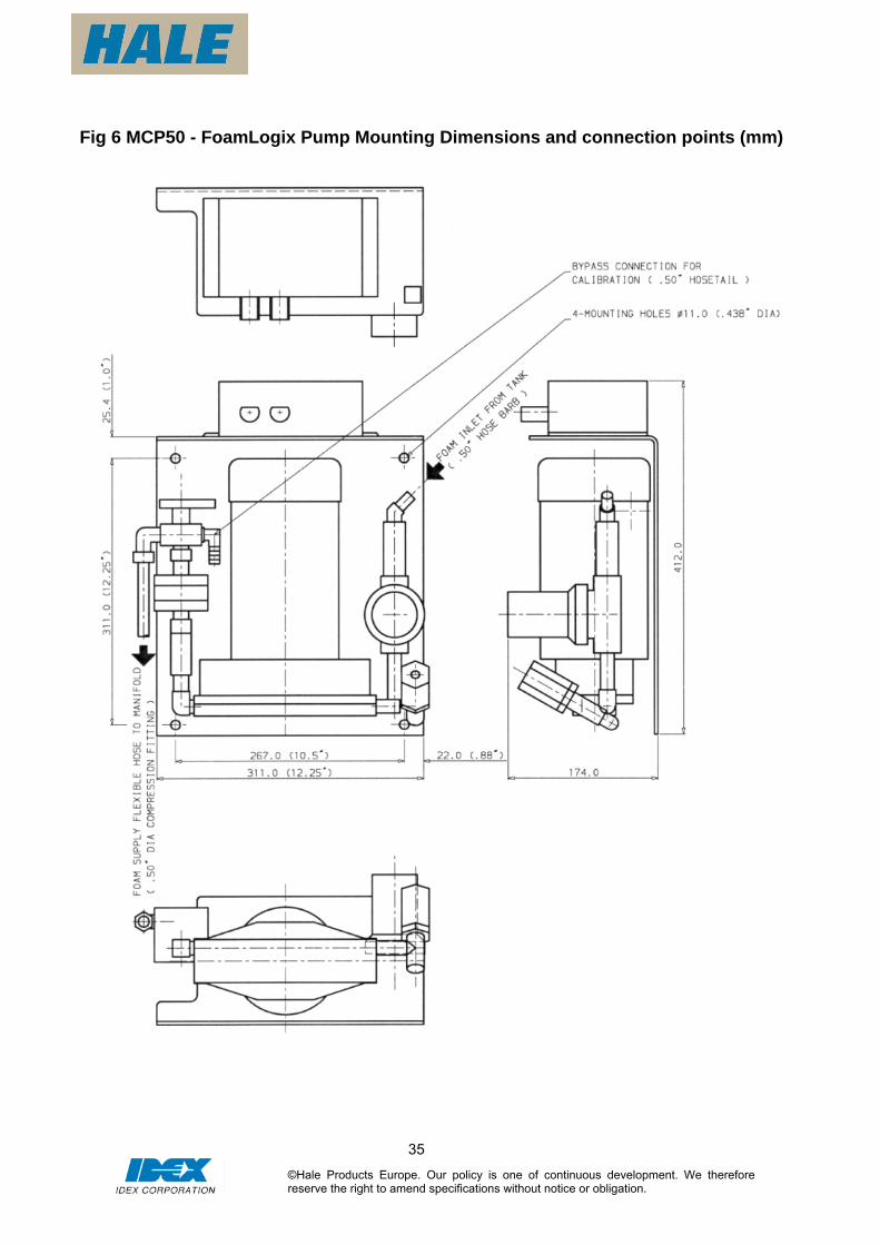
3. FoamLogix Pump
3.1. The Foam Pump should be securely mounted and positioned so that there is easy access to the foam agent filter and the pump lubrication point for maintenance.
tank position to ensure that a head of foam agent above the Foam pump is maintained.
ounting platform and anti vibration mounts. See Fig 6, at back of manual, for
Consideration should be given to the foam
dimensions.
Foam agent filter
Foam agent inlet
Foam agent outlet to manifold Bypass to foam tank for priming/calibration
y)
Bypass switch Mounting frame (below pump bod
©Hale Products Europe. Our policy is one of continuous development. We therefore reserve the right to amend specifications without notice or obligation.

C3.2. onnect the foam pump outlet to the inlet connection on the manifold using a 0.5inch I.D. flexible hose with 0.5inch – 14 NPT compression fittings. Tighten the hose connections securely to ensure that there is no foam agent leakage.
Foam inlet16
Foam inlet block can be rotated in 90°
increments to suit foam supply pipe.If block position is changed then previous stud holes must be blocked with grubscrews taken from unused holes.
©Hale Products Europe. Our policy is one of continuous development. We therefore reserve the right to amend specifications without notice or obligation.

17
4. FoamLogix Control Panel Moback ofThe ins ed to operate the unit. Electrical cable connections are made to the FoamLogix control unit, wet or dry foam indicator, wet or dry foam control switch, foam/CAFS selector switch and the compressor temperature warning light. The wiring diagram at the back of the manual shows
The compressor pressure gauge must be connected with 6mm nylon tubing to the T piece connection described in section 2.5. 5. Foam Tank
from an on board foam tank. This should be the FoamLogix pump. The Low-level switch
(Supplied) must be installed. Connect the low-level switch connection on the foam tank to e Interote: the low foam level switch must be installed in the tank in the correct orientation. The
switch de here the wires enter the device. This marker m osition for correct functioning. The foam tank requires a 23mm hole for secure fitting of the switch device and the maximum allowable thickness of tank wall material is 4mm. The switch device should be installed at a location in the tank wall that allows for activation when there are approximately 3 litres of foam left before running out.
The foam feed line should have a 13mm bore and be fitted with an isolating tap for maintenance purposes. The isolating tap should be located as close to the tank as possible. It is also good practise to provide a flushing point close to the isolating tap to ensure that the maximum length of hose line can be flushed out. The flushing line should also be fitted with an isolating valve. Note. The Foam pump filter is a low-pressure device, and should not be subjected to pressures greater than 10 Bar when flushing. The foam tank should be of plastic or stainless steel with a volume ≥ main tank volume x 0.005. Alternatively, a volume of at least 25litres may be preferred to allow an entire drum of foam agent to be contained. Connect the wiring harness to the Foam pump and manifold. The wiring diagram Fig 4 and photgraph 4A , at the back of the manual, shows the essential electrical connection
This marker must be at 12 o clock (top) when the switch device is installed
unt the instrument panel in an appropriate, and convenient location. Refer to Fig 7, at the the manual, for panel mounting details. trument panel contains all the control functions and data display need
the relevant connection points for the wiring harness.
The preferred method of supplying foam agent is mounted to give a slight head of foam agent to
thN
lock control module.
vice has a raised marker on the casing wust be installed at the 12 o clock (top) p
©Hale Products Europe. Our policy is one of continuous development. We therefore reserve the right to amend specifications without notice or obligation.
18
information. Route the wiring haSecure the wires in place and push the connectors together. Note: the ends are keyed and will only plug into the correct mating connector. Ifminimal force, do not force the connection. Instead, try joining a different combination. NOTES FOR A SUCCESSFUL INSTALLATION 1. The in-line strainer/valve assembly is a low-pressu
high flushing water pressure. It is rated for 10 Bar
2.
rness pigtails from the panel to the foam pump and section.
the connectors will not fit together with
re device and WILL NOT withstand
When determining the location of Hale FoamLogix components keep in mind piping runs, cable routing and other interferences that will hinder or interfere with proper system
.
each Hale FoamLogix system are indexed so they only go in et
roper
y are properly insulated and sealed using
6. The system can only perform when the electrical connections are sound. Verify all
7. d at the facto d.
damage these cables, which could result in other system damage.
8. Use mounting hardware that is compatible with all foam concentrates to be used in the
system. Use washers, lockwashers and capscrews made of brass or 300 series stainless steel.
d from
kpoint must be catered for. If the compressed is
performance 3. Prevent corrosion of power and ground connections by sealing these connections with
silicone sealant. 4. The cordsets provided with
the correct receptacle and they can only go in one way. When making cordsconnections DO NOT force mismatched connections as damage can result in impsystem operation.
5. When making wire connections make sure the
an adhesive filled heat shrink tubing.
electrical connections prior to start up.
Each Hale FoamLogix system is teste ry using the wiring harness provideImproper handling and forcing connections can
9. The areas containing the ptoMiniCAFS components must be adequately shieldethe ingress of road spray / debris and surplus grease from universal joints etc.. Ingress of dirt, water and grease will have a detrimental effect on the working life of the drive belt and electronics.
10. Access to compressor oil fill and level checair foam is to discharge through one or both of the side lockers and the vehicle builder fitting the necessary pipe work and isolating ball valves, then any pipe work or valves fitted should have a clear through bore of 38mm as far as the hose connector. Sealed blank caps MUST NOT be used on CAFS discharges. This is to prevent compressed air from being trapped in the pipe work.
©Hale Products Europe. Our policy is one of continuous development. We therefore reserve the right to amend specifications without notice or obligation.

19
11. The foam feed line should have a 1/2inch bore and be fitted with an isolating tap for maintenance purposes. The isolating tap and flushing point should be located as close tothe tank as possible, this ensures that the maximum length of hose line can be flushedout. The flushing line should also be fitted with an isolating valve.
orking from open water or a tank feed. It
must not be used directly from a pressurised suction (hydrant) because this will interfere
to maintain the water level in the ehicle tank.
ECOMMENDED FOAM AGENTS
12. The ptoMiniCAFS should only be used when w
with the water / air pressure ratio. If hydrant support is required this must be used onlyv
R
Cla Manufacturer Brand name
ss A Foam ANSUL Silvex Class A Foam
Concentrate Angus Forexpan S (0.1% - 1.0%) Chubb National Foam 1st Defense Class A
US Forestry Service Approved
Coldwater Foam Chubb National Foam Knock-Down Monsanto Phoscheck WD881 Chemonics Fire-Trol Fire Foam 103 Chemonics Fire-Trol Fire Foam 104 3M Light Water FT-1150 ChemGuard Class A Plus Unifoam Co Ltd. UniA 1%
Non U.S. Forestry Service Approved
3M Light Water SFFF
©Hale Products Europe. Our policy is one of continuous development. We therefore reserve the right to amend specifications without notice or obligation.

20
OPERATION
©Hale Products Europe. Our policy is one of continuous development. We therefore reserve the right to amend specifications without notice or obligation.

21
OPERATING THE SYSTEM Caution: The MCP50 should only be used when working from open water or a tank feed. It must not be used directly from a pressurised suction (hydrant) because this will interfere with the water / air pressure ratio. If hydrant support is required this must be used only to maintain the water level in the vehicle tank. Instrument panel features –
1234.5
CAFS
bar
psi
10
8
64
2
0
80
160
120
140
10060
0
20
40
iHALE
FoamLogix
FLOW % FLOW FOAMTOTAL
CAFSCOMP
DR
WETWET DRY
Not used
Wet or dry foam indicator
FoamLogix control unit
Compressor pressure gauge CAFS or Foam Selector Wet or dry foam selector
Compressor temperature warning light
©Hale Products Europe. Our policy is one of continuous development. We therefore reserve the right to amend specifications without notice or obligation.

22
COMMISSIONING/ START-UP PROCEDURE 1. Check that all the necessary connections have been made as described in the previous
sections
2. The compressor is filled with the required oil. Run the pump at 2-3 bar with compressor engaged
3. Run the compressor for 30 seconds to al w oil to circulate. 4. Stop unit and check compressor oil level top up if nece 5. a
e f , pa e 16 6. Ensure that there is s nt foam age the 7. Select simulated flow on
time. 8. button, and the pump will prime itself. The pump will run for 30
s or until prime is achieved. If no prime is made, the display will show “no pri”. Repeat this step once more to attempt to prime the pump. ”no Pr” = No prime display
lo
– ssary.
Turn the bypsuitable rece
ss valve on the FoamLogix to bypass (arrow points to left) and provide a olle to c ct th oam agent. See g .ptacle
ufficie nt in tank.
the FoamLogix by pressing both up ↑ & down ↓ at the same
Press thsecond
e red on
9. When prime is achieved, deselect simulated flow by pressing both up ↑ & down ↓ at the
same time. 10. Return the bypass valve to the inject position (arrow points to right). The unit is now ready to run.
©Hale Products Europe. Our policy is one of continuous development. We therefore reserve the right to amend specifications without notice or obligation.

23
OPERATING MCP50 FROM A VEHICLE WATER SOURCE
Cdiameter layflat hose is suitable for delivering compressed air foam. If a single discharge is being used, a φ25 to φ38mm smooth bore nozzle would be suitable. If two delivery h s would be appropriate. Noteth ever, the scrubbing action of the foam on the hose wall tends to improve the foam quality. Note: A standard fog nozzle can be used with CAFS if used on the ‘Flush’ setting. Using th Note:
1. onnect a suitable delivery hose and branch to the CAFS discharge. φ38 to φ45mm
oses were to be deployed, then two φ19 nozzle
: The best foam quality is produced using a smooth bore nozzle with the foam going rough the minimum number of valves and sharp bends. How
e ‘Fog’ settings will severely degrade the foam quality.
the following controls on the FoamLogix Control Panel -
. Discharging Water / Foam Agent Mixture (Can be operated from open water, tank, or
2.1. Set pump at required pressure only option is selected by pressing the bottom of the
Foam/CAFS selector switch, marked with the symbol -
2hydrant into pump suction)
2.2. Ensure that the foam
©Hale Products Europe. Our policy is one of continuous development. We therefore reserve the right to amend specifications without notice or obligation.
(P22) 2.3. Press the red on button, and choose desired foam % setting. (Default is 0.5%)
Foam % Press ↑ to increase foam % Press ↓ to decrease foam %

24
©Hale Products Europe. Our policy is one of continuous development. We therefore reserve the right to amend specifications without notice or obligation.
te: the WET/DRY control (ARC valve) is only operable
2.4. Open CAFS discharge valves to deliver foam agent. No when CAFS is selected. The control will default to the wet condition when CAFS is turned off.
. Discharging CAFS (Can be operated from open water or tank feed only. Do not apply hydrant pressure to pump suction)
3.1. Bring pump to idle. 3.2. Select CAFS by pressing the top of the CAFS selector switch – marked “CAFS”
(Page 22) Increase pump speed to required operating pressure (4-10 Bar)
4. Wet Foam or Dry Foam 4.1. A continuous variable foam type from WET to DRY is available, selectable by the
pump operator. 4.2. The WET or DRY foam composition is selected by using the WET/DRY control on the
panel (Page 22). An indication of foam type is given by the WET or DRY foam indicator (Page 22), but the pump operator may choose to optimise the liquid flow as displayed in the Foamlogix display.
4.3. To increase the WET or DRY property of the foam, press the WET/DRY control (Page 22) at the top for WET or the bottom for DRY.
4.4. Note: when discharging dry foam at low pump pressure, the possibility of hose kinking is increased and should be considered when deploying hoses on the fire ground.
Shutting Down 5.1. Set WET/DRY selector switch to the WET foam setting (Press in bottom of switch) 5.2.
3
5.
Turn off compressor by setting the Foam/CAFS selector switch to foam position -
5.3. Turn off the FoamLogix, press RED button.
5.6.
5.8. If cold weather is expected, open the drains to drain the manifold.
6. Overheat Shut down
5.4. Bring pump to fast idle. 5.5. Run water through the CAFS discharge system to flush out the foam agent.
Close the CAFS discharge valves 5.7. Disengage PTO.

25
If the compressor is running hot, a warning indicator light will illuminate on the control panel when oil temperature reaches 105oC (Page 22). If the compressor oil temperature exceeds 110º C, the unit should disengage the drive automatically. The compressor can sustain 105º C temperatures for short periods without damage. The unit can be re-engaged when the compressor has cooled. The most likely cause of compressor overheat problems is insufficient cooling water flow.
©Hale Products Europe. Our policy is one of continuous development. We therefore reserve the right to amend specifications without notice or obligation.

26
MAINTENANCE SCHEDULE Monthly:
Change compressor oil and filter. Filter P/N 59271/01 Clean the FoamLogix foam filter.
Annually or every 400 hours: Change the compressor air cleaner - P/N 59271
Every Two Years:
Change drive belt
Note: Both the drive belt and the air cleaner may have to be changed more often in
dusty/dirty/heavy duty applications.
FAULT FINDING
Check the compressor oil level and top up if necessary. Check the belt tension/condition and adjust if necessary. Check the hose connections.
Every 100 hours or every 6 months (whichever comes first):
EFFECT CAUSE ACTION Compressor overheats No water supply or restricted flow Turn on water supply.
Check oil cooler pipe work for obstructions
Unable to produce foam solution
FoamLogix not operating Switch on FoamLogix Blown Fuse (Investigate cause)
No Foam in tank Refill with foam agent FoamLogix not Primed Prime FoamLogix No air injection Compressor not selected Turn switch on Low foam switch activated Refill foam Tank FoamLogix not on Turn FoamLogix on Air and liquid not mixing (Slugflow)
Depleted foam supply (Low level switch not fitted) Foam % set too low
Refill foam tank Increase foam % setting
Surging of hose and pressure gauge.
Insufficient air pressure in hose Increase compressor speed if not at maximum. Reduce nozzle diameter.
©Hale Products Europe. Our policy is one of continuous development. We therefore reserve the right to amend specifications without notice or obligation.

27
PTO Mini CAFS
No Air Inject Fault Tree
NO AIR INJECTION
I LO
CH AC
S W LEVELTIVATED
FOAMSWIT
REPLENISH FOAM TANK
Yes
TEST FLOWSENSOR &
WIRING NNECTIONSCO
CHECK AIR VALVE AND PIPE WORK .REPLACE INTERLOCK
CONTROL
REPLACE SOLENOID VALVE
IS FOAMLOGIX TURNED ON
NoTURN FOAMLOGIX ON.
SET REQ`D %
IS CAFSSWITCH ON
TURN ON CAFS
Yes
No
IS COMPRESSOR RUNNING
CHECK BELT AND POWER SUPPLY TO
CLUTCH
Yes
Yes
No
DISCONNECT TO PROVE SWITCH FAULT
IS FLOWRATE REGISTERING WHEN DISCHARGING LIQUID
No
IS SOVALVE SEE
AND COCONNE TION
IS FREGIST
DISC
LENOIDING +12/24v
ON ATMMC
Yes PRESTEST BUTTOSOLENOI
No LOWRATEERING WHEN HARGING
LIQUID
No
REFER TTROUB
SN ON
D VALVE
DOES AINJECT
OCCU
IR ION R
No
O FOAMLOGIX LE SHOOTING GUIDE
No
Yes
No
Yes
©Hale Products Europe. Our policy is one of continuous development. We therefore reserve the right to amend specifications without notice or obligation.

28
INSTALLATION DRAWINGS
©Hale Products Europe. Our policy is one of continuous development. We therefore reserve the right to amend specifications without notice or obligation.

29
Fig 1 MCP50 – M
ain Components - Overview
FoamConcentrateSupply Tank
Foampump
ManifoldAssembly
Compressor
Air supply to Manifold
Foam Outlet
Coolingwater infrompump
CoolingSystem
Coolingwater outto pump
CAFS Discharge
Water inlet
Hale X-mixersystem
Hose
Flow metersignal
Flow meter
Foam Inlet
Low FoamSignal
FoamPumpSignal
FoamLogix Control Unit
©Hale Products Europe. Our policy is one of continuous development. We therefore reserve the right to amend specifications without notice or obligation.

30
Fig 2 MCP50 – Compressor dimensions and connection points (mm)
©Hale Products Europe. Our policy is one of continuous development. We therefore reserve the right to amend specifications without notice or obligation.

31
©Hale Products Europe. Our policy is one of continuous development. We therefore reserve the right to amend specifications without notice or obligation.
Fig 3 MCP50 – manifold dimensions and connection points (mm)

32
Fig 4 MCP50 – Electrical connection information Fig 4A Electrical and foam Connections Overview
©Hale Products Europe. Our policy is one of continuous development. We therefore reserve the right to amend specifications without notice or obligation.

33
©Hale Products Europe. Our policy is one of continuous development. We therefore reserve the right to amend specifications without notice or obligation.
Manifold
Flow sensorcable
Safety InterlockCAN-BUSconnection
Low foam levelswitch connecti
Power andcommon displa
Unused
Foam supply tomanifold
Foam supplyfrom tank
Foam flushingloop
Foam Pump
on
y

34
Fig 5 Pneumatic connections
Compressor
Manifold
Manifold
CAFS AirCo nne ction s - 0.75 ” BSPHo se - minimum 19 mm IDSAE 10 0 R6 Hose
Signal AirPush-in fittings6mm nylon tubing
T piece
CompressorPressure G auge
Compressor
Compressor AirPush-in fittings6mm nylon tubing
©Hale Products Europe. Our policy is one of continuous development. We therefore reserve the right to amend specifications without notice or obligation.
35
Fig 6 MCP50 - FoamLogix Pump Mounting Dimensions and connection points (mm)
©Hale Products Europe. Our policy is one of continuous development. We therefore reserve the right to amend specifications without notice or obligation.

36
Fig 7 MCP50 - FoamLogix Control Panel – Cut-out information for mounting Dimensions in mm
88
4 – Mounting holes Dia 6.5
Air supply from “X”
125
1234.
CAF
ba
p
1
8
64
2
0
8
160
120
140
10060
0
20
40
i
HAL
FoamLogi
CAFCOM
DR
WEWEDR
235
219
186 170
47
©Hale Products Europe. Our policy is one of continuous development. We therefore reserve the right to amend specifications without notice or obligation.