Embed Size (px)
Citation preview

JLUPSE-001D
1 / 27
MURATA MANUFACTURING Co., LTD.
Proximity/Ambient Light Sensor
Delivery Specification
Model Name : LT-1PA01
Murata Manufacturing Co., Ltd.
Device Development Sec.1
Sensor Products Dept.2
Sensor Products Division
JLUPSE-001D
2 / 27
MURATA MANUFACTURING Co., LTD.
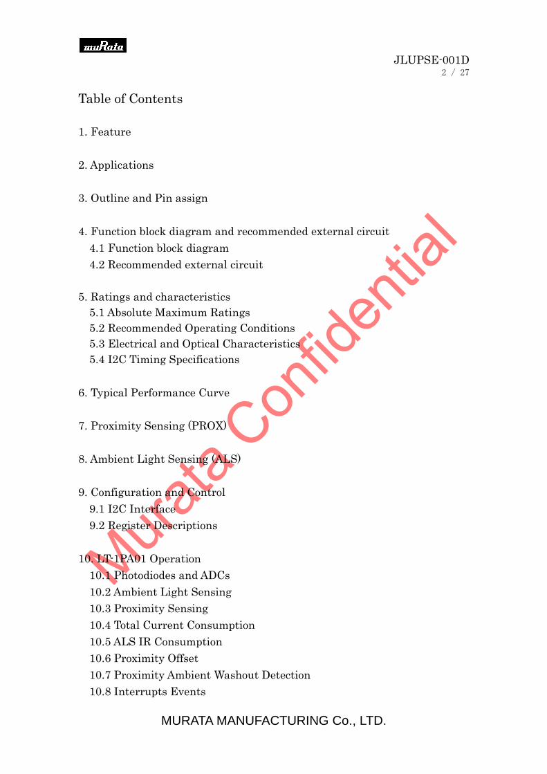
Table of Contents
1. Feature
2. Applications
3. Outline and Pin assign
4. Function block diagram and recommended external circuit
4.1 Function block diagram
4.2 Recommended external circuit
5. Ratings and characteristics
5.1 Absolute Maximum Ratings
5.2 Recommended Operating Conditions
5.3 Electrical and Optical Characteristics
5.4 I2C Timing Specifications
6. Typical Performance Curve
7. Proximity Sensing (PROX)
8. Ambient Light Sensing (ALS)
9. Configuration and Control
9.1 I2C Interface
9.2 Register Descriptions
10. LT-1PA01 Operation
10.1 Photodiodes and ADCs
10.2 Ambient Light Sensing
10.3 Proximity Sensing
10.4 Total Current Consumption
10.5 ALS IR Consumption
10.6 Proximity Offset
10.7 Proximity Ambient Washout Detection
10.8 Interrupts Events

JLUPSE-001D
3 / 27
MURATA MANUFACTURING Co., LTD.
10.9 Interrupts Persistence
10.10 Power-UP and Brown-Out Reset
10.11 Power-Down
10.12 Soft Reset
10.13 ALS Data Count Read Out
10.14 Proximity Detection of Various Objects
11. Reliability
12. Outgoing Inspection
13. Recommended Land pattern
14. In case of solder reflow
15. Packaging and Indication
15.1 Tape structures and Dimensions and Product insertion
15.2 Reel structures and Dimensions
15.3 Packaging Material
15.4 Packing and Shipping Label
16. Other
16.1 Cautions
16.2 Fail-safe
16.3 Precautions for use
16.4 Notice in handling and storage
16.5 Notice (soldering and mounting)
17. Notice

JLUPSE-001D
4 / 27
MURATA MANUFACTURING Co., LTD.
The specification applies to the outline and characteristics of
proximity/ambient light sensor, Model No. LT-1PA01.
LT-1PA01 is a low power Ambient Light Sensor (ALS) and proximity (PROX)
sensor. It has a built-in IR-Emitter driver for proximity function.
The IR emitter driver is optimized for interfacing to low power coherent light
sources.
The ALS function measures amount of light (in the visible spectrum)
incident on the LT-1PA01 device.
The ALS function has a programmable ambient IR-rejection which allows
fine tuning of light source variations and is ideal for light sensor applications
under dark protective glass. The ALS provides a 12-bit measurement.
A passive optical filter removes unwanted wavelengths (IR or Ultraviolet) to
ensure accurate ALS measurement.
The built-in current-driver pulses an internal infrared emitter at a
programmed current for 96μs. The infrared light that is reflected and
received by LT-1PA01 is digitized by an 8-bit ADC.
The proximity sensor also has a passive optical filter designed to pass IR and
reject visible wavelengths.
The LT-1PA01 provides a hardware pad to indicate an interrupt event.
The interrupt pad saves power as the host microcontroller can ‘wake-up’ on
an interrupt event and does not need to poll the device for an interrupt event.
The interrupt generator is user configurable and provides several options for
ALS and PROX trigger configurations. The LT-1PA01 supports an SMBus
compatible I2C interface for configuration and control
JLUPSE-001D
5 / 27
MURATA MANUFACTURING Co., LTD.
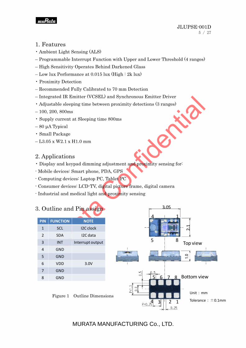
1. Features
• Ambient Light Sensing (ALS)
– Programmable Interrupt Function with Upper and Lower Threshold (4 ranges)
– High Sensitivity Operates Behind Darkened Glass
– Low lux Performance at 0.015 lux (High : 2k lux)
• Proximity Detection
– Recommended Fully Calibrated to 70 mm Detection
– Integrated IR Emitter (VCSEL) and Synchronous Emitter Driver
• Adjustable sleeping time between proximity detections (3 ranges)
– 100, 200, 800ms
• Supply current at Sleeping time 800ms
– 80 μA Typical
• Small Package
– L3.05 x W2.1 x H1.0 mm
2. Applications
• Display and keypad dimming adjustment and proximity sensing for:
- Mobile devices: Smart phone, PDA, GPS
- Computing devices: Laptop PC, Tablet PC
- Consumer devices: LCD-TV, digital picture frame, digital camera
- Industrial and medical light and proximity sensing
3. Outline and Pin assign
PIN FUNCTION NOTE
1 SCL I2C clock
2 SDA I2C data
3 INT Interrupt output
4 GND
5 GND
6 VDD 3.0V
7 GND
8 GND
4
85
1
4
85
13
6 7
2
Top view
Bottom view
3.05
2.1
Figure 1 Outline Dimensions Unit:mm
Tolerance:±0.1mm
1.0
JLUPSE-001D
6 / 27
MURATA MANUFACTURING Co., LTD.
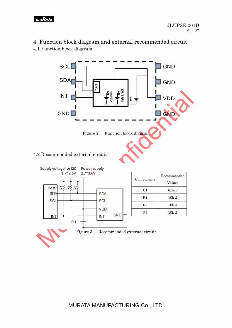
4. Function block diagram and external recommended circuit
4.1 Function block diagram
Figure 2 Function block diagram
4.2 Recommended external circuit
Figure 3 Recommended external circuit
Vis
ible
Infr
are
d
I2C
SCL
SDA
INT
GND
GND
VDD
GNDGND
Components Recommended
Values
C1 0.1uF
R1 10kΩ
R2 10kΩ
R3 10kΩ
VDD
GND
SDA
SCL
INT
SCL
INT
SDA
Host
3.3V
C1
R3
R2
R1
3.3V
JLUPSE-001D
7 / 27
MURATA MANUFACTURING Co., LTD.
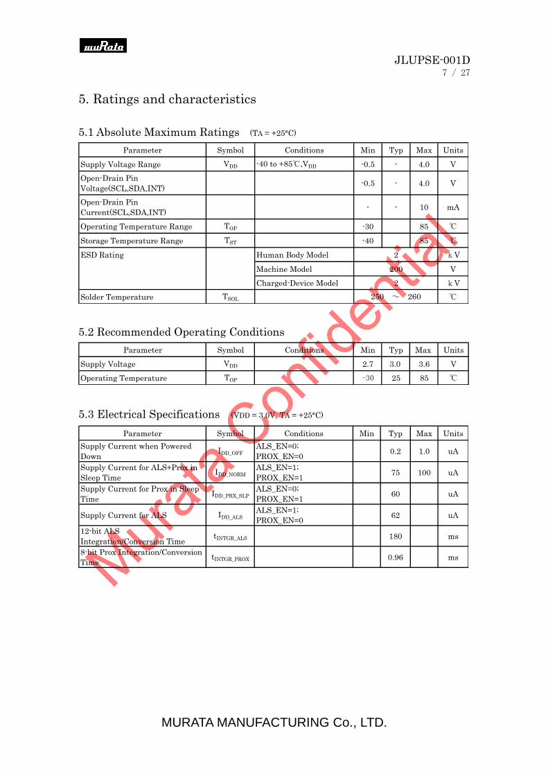
5. Ratings and characteristics
5.1 Absolute Maximum Ratings (TA = +25°C)
Parameter Symbol Conditions Min Typ Max Units
Supply Voltage Range VDD -40 to +85℃,VDD -0.5 - 4.0 V
Open-Drain Pin
Voltage(SCL,SDA,INT)-0.5 - 4.0 V
Open-Drain Pin
Current(SCL,SDA,INT)- - 10 mA
Operating Temperature Range TOP -30 85 ℃
Storage Temperature Range TST -40 85 ℃
ESD Rating Human Body Model 2 kV
Machine Model 200 V
Charged-Device Model 2 kV
Solder Temperature TSOL ℃250 ~ 260
5.2 Recommended Operating Conditions
Parameter Symbol Conditions Min Typ Max Units
Supply Voltage VDD 2.7 3.0 3.6 V
Operating Temperature TOP -30 25 85 ℃
5.3 Electrical Specifications (VDD = 3.0V, TA = +25°C)
Parameter Symbol Conditions Min Typ Max Units
Supply Current when Powered
DownIDD_OFF
ALS_EN=0;
PROX_EN=00.2 1.0 uA
Supply Current for ALS+Prox in
Sleep TimeIDD_NORM
ALS_EN=1;
PROX_EN=175 100 uA
Supply Current for Prox in Sleep
TimeIDD_PRX_SLP
ALS_EN=0;
PROX_EN=160 uA
Supply Current for ALS IDD_ALS
ALS_EN=1;
PROX_EN=062 uA
12-bit ALS
Integration/Conversion TimetINTGR_ALS 180 ms
8-bit Prox Integration/Conversion
TimetINTGR_PROX 0.96 ms
JLUPSE-001D
8 / 27
MURATA MANUFACTURING Co., LTD.
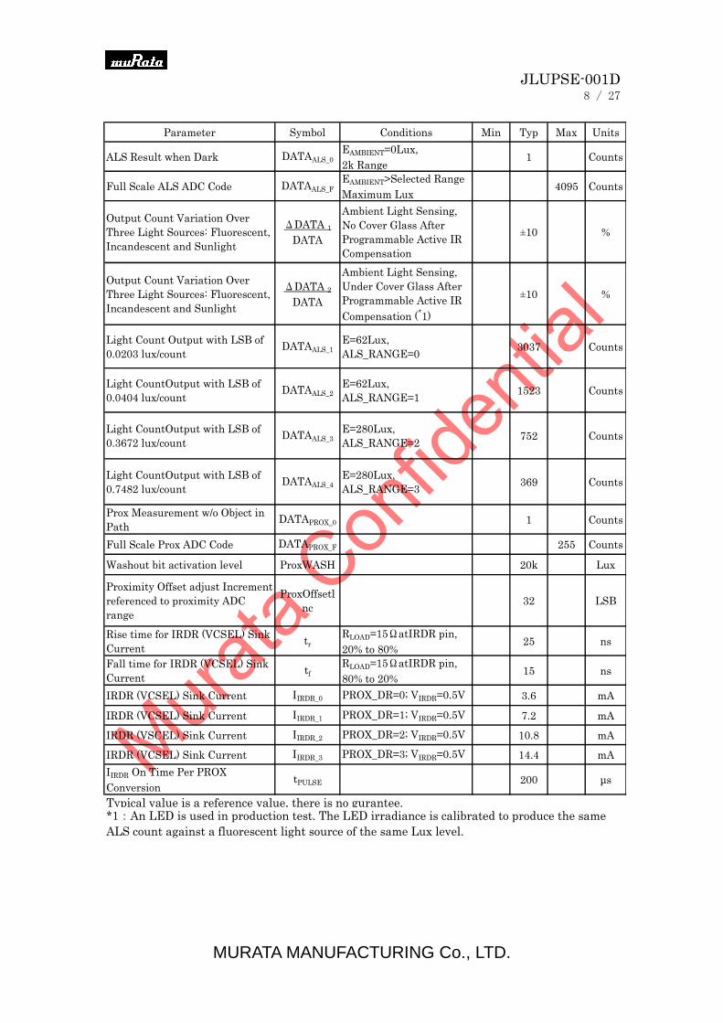
Parameter Symbol Conditions Min Typ Max Units
ALS Result when Dark DATAALS_0
EAMBIENT=0Lux,
2k Range1 Counts
Full Scale ALS ADC Code DATAALS_F
EAMBIENT>Selected Range
Maximum Lux4095 Counts
Output Count Variation Over
Three Light Sources: Fluorescent,
Incandescent and Sunlight
ΔDATA 1
DATA
Ambient Light Sensing,
No Cover Glass After
Programmable Active IR
Compensation
±10 %
Output Count Variation Over
Three Light Sources: Fluorescent,
Incandescent and Sunlight
ΔDATA 2
DATA
Ambient Light Sensing,
Under Cover Glass After
Programmable Active IR
Compensation (*1)
±10 %
Light Count Output with LSB of
0.0203 lux/countDATAALS_1
E=62Lux,
ALS_RANGE=03037 Counts
Light CountOutput with LSB of
0.0404 lux/countDATAALS_2
E=62Lux,
ALS_RANGE=11523 Counts
Light CountOutput with LSB of
0.3672 lux/countDATAALS_3
E=280Lux,
ALS_RANGE=2752 Counts
Light CountOutput with LSB of
0.7482 lux/countDATAALS_4
E=280Lux,
ALS_RANGE=3369 Counts
Prox Measurement w/o Object in
PathDATAPROX_0 1 Counts
Full Scale Prox ADC Code DATAPROX_F 255 Counts
Washout bit activation level ProxWASH 20k Lux
Proximity Offset adjust Increment
referenced to proximity ADC
range
ProxOffsetl
nc32 LSB
Rise time for IRDR (VCSEL) Sink
Currenttr
RLOAD=15ΩatIRDR pin,
20% to 80%25 ns
Fall time for IRDR (VCSEL) Sink
Currenttf
RLOAD=15ΩatIRDR pin,
80% to 20%15 ns
IRDR (VCSEL) Sink Current IIRDR_0 PROX_DR=0; VIRDR=0.5V 3.6 mA
IRDR (VCSEL) Sink Current IIRDR_1 PROX_DR=1; VIRDR=0.5V 7.2 mA
IRDR (VSCEL) Sink Current IIRDR_2 PROX_DR=2; VIRDR=0.5V 10.8 mA
IRDR (VCSEL) Sink Current IIRDR_3 PROX_DR=3; VIRDR=0.5V 14.4 mA
IIRDR On Time Per PROX
ConversiontPULSE 200 μs
*1:An LED is used in production test. The LED irradiance is calibrated to produce the same
ALS count against a fluorescent light source of the same Lux level.
Typical value is a reference value, there is no gurantee.

JLUPSE-001D
9 / 27
MURATA MANUFACTURING Co., LTD.
5.4 I2C Electrical specification (VDD = 3.0V, TA = +25°C)
Parameter Symbol Conditions Min Typ Max Unit
sSupply Voltage Range for I2C
Interface
VI2C 1.7 3.6 V
SCL and SDA Input Low Voltage VIL 0.55 V
SCL and SDA Input High Voltage VIH 1.25 V
Hysteresis of Schmitt Trigger Input Vhys0.05
VDDV
Low-level output voltage (open-drain)
at 4mA sink currentVOL 0.4 V
Input Leakage for each SDA, SCL pin Ii -10 10 μA
Pulse Width of Spikes that must be
Suppressed by the Input FiltertSP 50 ns
SCL Falling Edge to SDA Output
Data ValidtAA 900 ns
Capacitance for each SDA and SCL
pin
Ci 10 pF
Hold Time (Repeated) START
ConditiontHD:STA
After this period, the
first clock pulse is
generated
600 ns
LOW Period of the SCL clock tLOW
Measured at the 30% of
VDD crossing1300 ns
HIGH period of the SCL Clock tHIGH 600 ns
Set-up Time for a Repeated START
ConditiontSU:STA 600 ns
Data Hold Time tHD:DAT 30 ns
Data Set-up Time tSU:DAT 100 ns
Rise Time of both SDA and SCL
SignalstR
20
+0.1xC
b
ns
Fall Time of both SDA and SCL
SignalstF
20
+0.1xC
b
ns
Set-up Time for STOP Condition tSU:STO 600 ns
Bus Free Time Between a STOP and
START ConditiontBUF 1300 ns
Capacitive Load for Each Bus Line Cb 400 pF
SDA and SCL System Bus Pull-up
ResistorRpull-up
Maximum is
determined by tR and
tF
1 kΩ
Data Valid Time tVD;DAT 0.9 μs
Data Valid Acknowledge Time tVD:ACK 0.9 μs
Noise Margin at the LOW Level VnL
0.1VD
DV
Noise Margin at the HIGH Level VnH
0.2VD
DV
・Cover glass assumes fixed infrared/visible ratio
NOTES:
JLUPSE-001D
10 / 27
MURATA MANUFACTURING Co., LTD.
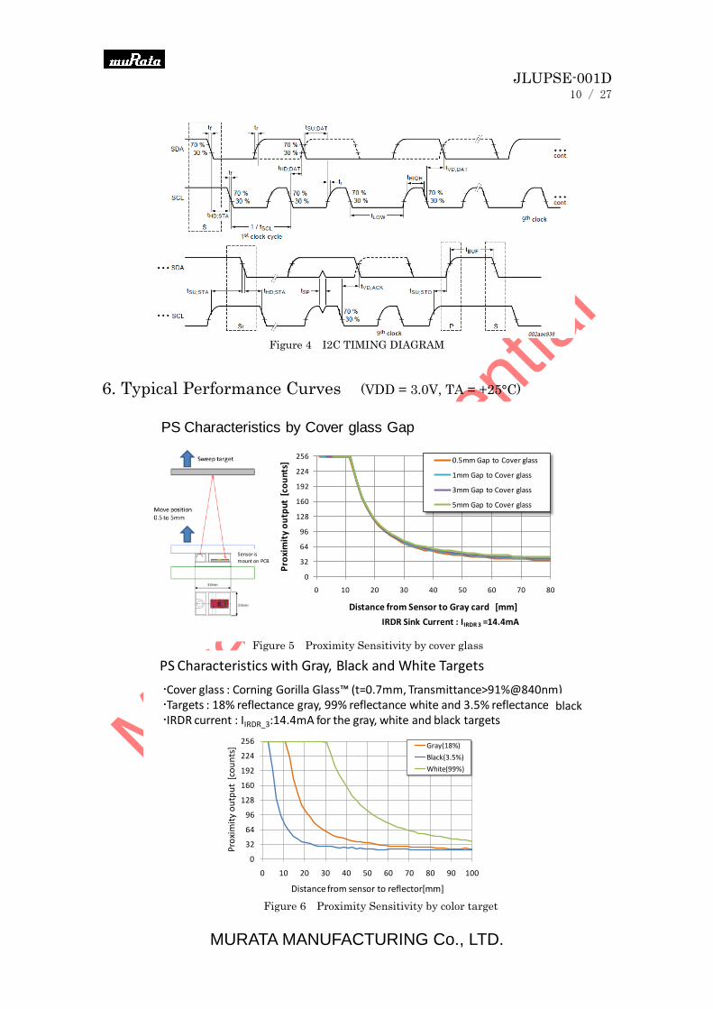
Figure 4 I2C TIMING DIAGRAM
6. Typical Performance Curves (VDD = 3.0V, TA = +25°C)
PS Characteristics by Cover glass Gap
0
32
64
96
128
160
192
224
256
0 10 20 30 40 50 60 70 80
Pro
xim
ity
ou
tpu
t [
cou
nts
]
Distance from Sensor to Gray card [mm]
0.5mm Gap to Cover glass
1mm Gap to Cover glass
3mm Gap to Cover glass
5mm Gap to Cover glass
Sensor is
mount on PCB
IRDR Sink Current : IIRDR 3 =14.4mA
PS Characteristics by Cover glass Gap with gray card
Sweep target
Move position0.5 to 5mm
Sensor is mountedon PCB
0
32
64
96
128
160
192
224
256
0 10 20 30 40 50
Pro
xim
ity
ou
tpu
t [c
ou
nts
]
Distance from Sensor to Gray card [mm]
0mm Gap to Cover glass
0.5mm Gap to Cover glass
1.0mm Gap to Cover glass
1.5mm Gap to Cover glass
2.0mm Gap to Cover glass
2.5mm Gap to Cover glass
3.0mm Gap to Cover glass
3.5mm Gap to Cover glass
4.0mm Gap to Cover glass
4.5mm Gap to Cover glass
5.0mm Gap to Cover glass
IRDR Sink Current : IIRDR_3 =14.4mA
PS Characteristics with Gray, Black and White Targets
Cover glass : Corning Gorilla Glass™ (t=0.7mm, Transmittance>91%@840nm)Targets : 18% reflectance gray, 99% reflectance white and 3.5% reflectance blackIRDR current : IIRDR_3:14.4mA for the gray, white and black targets
IIRDR_0:3.6mA for the white target
0
32
64
96
128
160
192
224
256
0 10 20 30 40 50
Pro
xim
ity
ou
tput
/cou
nts
Distance to target/mm
Gray(18%), ILD=14.4mA
Black(3.5%), ILD=14.4mA
White(99%), ILD=14.4mA
Noise(26 counts), ILD=14.4mA
White(99%), ILD=3.6mA
Noise(7 counts), ILD=3.6mA
IRDR:14.4mA
IRDR:14.4mA
IRDR:14.4mA
IRDR:14.4mA
IRDR:3.6mA
IRDR:3.6mA
0
32
64
96
128
160
192
224
256
0 10 20 30 40 50 60 70 80 90 100
Pro
xim
ity
ou
tpu
t [c
ou
nts
]
Distance from sensor to reflector[mm]
Gray(18%)
Black(3.5%)
White(99%)
Figure 5 Proximity Sensitivity by cover glass
Figure 6 Proximity Sensitivity by color target
black
JLUPSE-001D
11 / 27
MURATA MANUFACTURING Co., LTD.
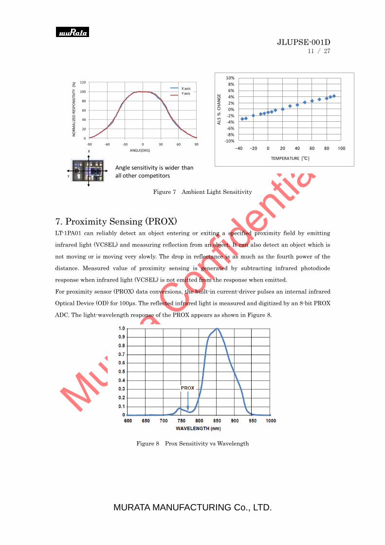
7. Proximity Sensing (PROX) LT-1PA01 can reliably detect an object entering or exiting a specified proximity field by emitting
infrared light (VCSEL) and measuring reflection from an object. It can also detect an object which is
not moving or is moving very slowly. The drop in reflectance is as much as the fourth power of the
distance. Measured value of proximity sensing is generated by subtracting infrared photodiode
response when infrared light (VCSEL) is not emitted from the response when emitted.
For proximity sensor (PROX) data conversions, the built-in current-driver pulses an internal infrared
Optical Device (OD) for 100μs. The reflected infrared light is measured and digitized by an 8-bit PROX
ADC. The light-wavelength response of the PROX appears as shown in Figure 8.
Figure 8 Prox Sensitivity vs Wavelength
0
20
40
60
80
100
120
-90 -60 -30 0 30 60 90
規格化
ALS感度
回転角/°
X軸回り
Y軸回り
Angle sensitivity is wider than all other competitors
ANGLE(DEG)
NO
RM
ALI
ZED
RES
PO
NSI
TIV
TY
(%)
X axisY axis
Y
X
-10%
-8%
-6%
-4%
-2%
0%
2%
4%
6%
8%
10%
-40 -20 0 20 40 60 80 100
ALS
% C
HA
NG
E
TEMPERATURE [℃]
Figure 7 Ambient Light Sensitivity
JLUPSE-001D
12 / 27
MURATA MANUFACTURING Co., LTD.
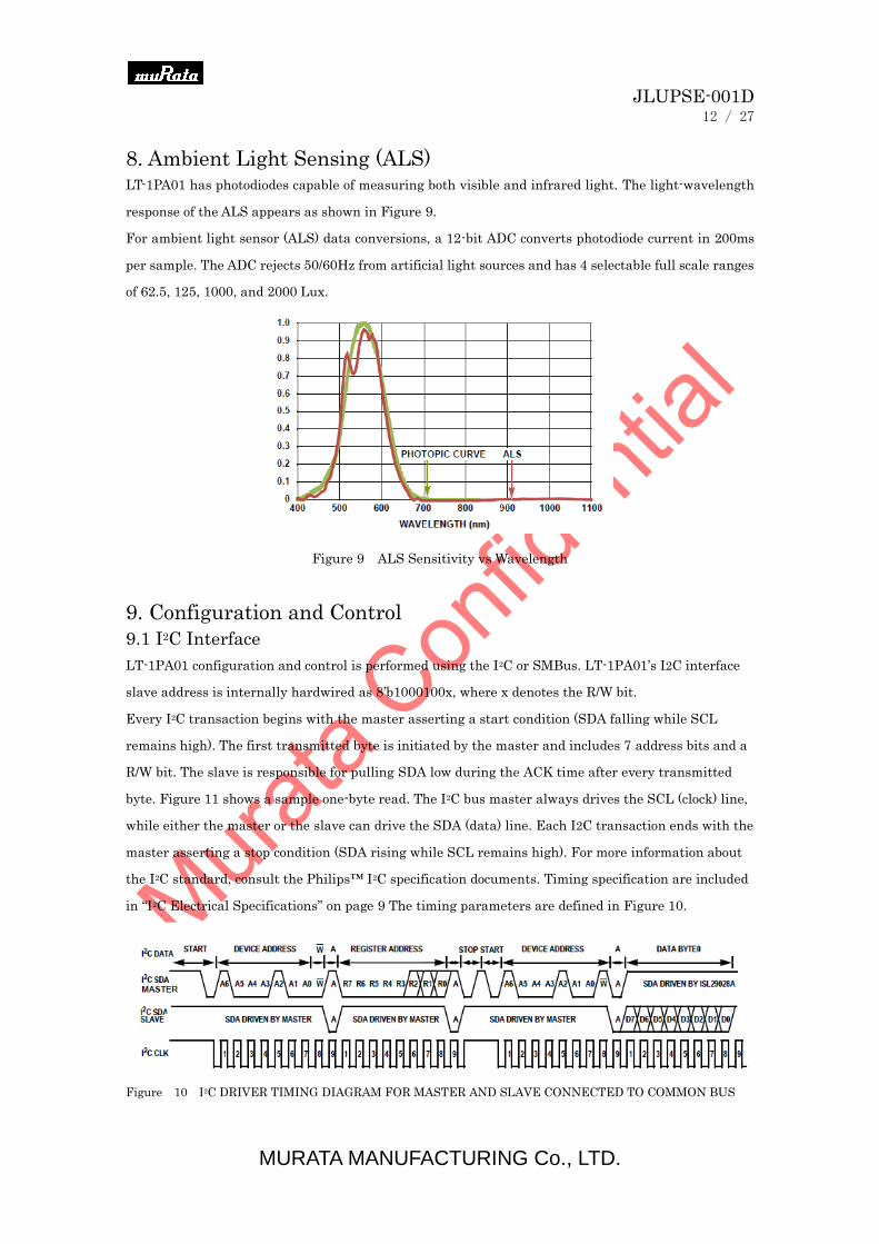
8. Ambient Light Sensing (ALS) LT-1PA01 has photodiodes capable of measuring both visible and infrared light. The light-wavelength
response of the ALS appears as shown in Figure 9.
For ambient light sensor (ALS) data conversions, a 12-bit ADC converts photodiode current in 200ms
per sample. The ADC rejects 50/60Hz from artificial light sources and has 4 selectable full scale ranges
of 62.5, 125, 1000, and 2000 Lux.
Figure 9 ALS Sensitivity vs Wavelength
9. Configuration and Control
9.1 I2C Interface
LT-1PA01 configuration and control is performed using the I2C or SMBus. LT-1PA01’s I2C interface
slave address is internally hardwired as 8’b1000100x, where x denotes the R/W bit.
Every I2C transaction begins with the master asserting a start condition (SDA falling while SCL
remains high). The first transmitted byte is initiated by the master and includes 7 address bits and a
R/W bit. The slave is responsible for pulling SDA low during the ACK time after every transmitted
byte. Figure 11 shows a sample one-byte read. The I2C bus master always drives the SCL (clock) line,
while either the master or the slave can drive the SDA (data) line. Each I2C transaction ends with the
master asserting a stop condition (SDA rising while SCL remains high). For more information about
the I2C standard, consult the Philips™ I2C specification documents. Timing specification are included
in “I2C Electrical Specifications” on page 9 The timing parameters are defined in Figure 10.
Figure 10 I2C DRIVER TIMING DIAGRAM FOR MASTER AND SLAVE CONNECTED TO COMMON BUS
JLUPSE-001D
13 / 27
MURATA MANUFACTURING Co., LTD.
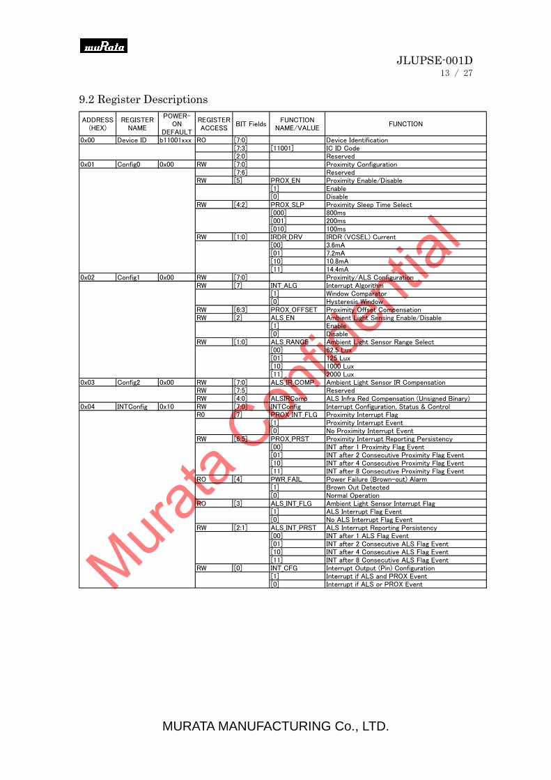
9.2 Register Descriptions
ADDRESS(HEX)
REGISTERNAME
POWER-ON
DEFAULT
REGISTERACCESS
BIT FieldsFUNCTION
NAME/VALUEFUNCTION
0x00 Device ID b11001xxx RO [7:0] Device Identification[7:3] [11001] IC ID Code[2:0] Reserved
0x01 Config0 0x00 RW [7:0] Proximity Configuration[7:6] Reserved
RW [5] PROX_EN Proximity Enable/Disable[1] Enable[0] Disable
RW [4:2] PROX_SLP Proximity Sleep Time Select[000] 800ms[001] 200ms[010] 100ms
RW [1:0] IRDR_DRV IRDR (VCSEL) Current[00] 3.6mA[01] 7.2mA[10] 10.8mA[11] 14.4mA
0x02 Config1 0x00 RW [7:0] Proximity/ALS ConfigurationRW [7] INT_ALG Interrupt Algorithm
[1] Window Comparator[0] Hysteresis Window
RW [6:3] PROX_OFFSET Proximity Offset CompensationRW [2] ALS_EN Ambient Light Sensing Enable/Disable
[1] Enable[0] Disable
RW [1:0] ALS_RANGE Ambient Light Sensor Range Select[00] 62.5 Lux[01] 125 Lux[10] 1000 Lux[11] 2000 Lux
0x03 Config2 0x00 RW [7:0] ALS_IR_COMP Ambient Light Sensor IR CompensationRW [7:5] ReservedRW [4:0] ALSIRComp ALS Infra Red Compensation (Unsigned Binary)
0x04 INTConfig 0x10 RW [7:0] INTConfig Interrupt Configuration, Status & ControlR0 [7] PROX_INT_FLG Proximity Interrupt Flag
[1] Proximity Interrupt Event[0] No Proximity Interrupt Event
RW [6:5] PROX_PRST Proximity Interrupt Reporting Persistency[00] INT after 1 Proximity Flag Event[01] INT after 2 Consecutive Proximity Flag Event[10] INT after 4 Consecutive Proximity Flag Event[11] INT after 8 Consecutive Proximity Flag Event
RO [4] PWR_FAIL Power Failure (Brown-out) Alarm[1] Brown Out Detected[0] Normal Operation
RO [3] ALS_INT_FLG Ambient Light Sensor Interrupt Flag[1] ALS Interrupt Flag Event[0] No ALS Interrupt Flag Event
RW [2:1] ALS_INT_PRST ALS Interrupt Reporting Persistency[00] INT after 1 ALS Flag Event[01] INT after 2 Consecutive ALS Flag Event[10] INT after 4 Consecutive ALS Flag Event[11] INT after 8 Consecutive ALS Flag Event
RW [0] INT_CFG Interrupt Output (Pin) Configuration[1] Interrupt if ALS and PROX Event[0] Interrupt if ALS or PROX Event

JLUPSE-001D
14 / 27
MURATA MANUFACTURING Co., LTD.
ADDRESS(HEX)
REGISTERNAME
POWER-ON
DEFAULT
REGISTERACCESS
BIT FieldsFUNCTION
NAME/VALUEFUNCTION
0x05 PROX_INT_TL 0x00 RW [7:0] PROX_INT_TL Proximity Interrupt LOW threshold0x06 PROX_INT_TH 0xFF RW [7:0] PROX_INT_TH Proximity Interrupt HIGH threshold0x07 ALS_INT_TL 0x00 RW [7:0] ALS_INT_TL1 ALS Interrupt LOW threshold bit[11:4]0x08 ALS_INT_TLH 0x0F RW [7:0] ALS Interrupt LOW/HIGH threshold bits
[7:4] ALS_INT_TL0 ALS Interrupt LOW threshold bit[3:0][3:0] ALS_INT_TH1 ALS Interrupt HIGH threshold bit[11:8]
0x09 ALS_INT_TH 0xFF RW [7:0] ALS_INT_TH0 ALS Interrupt HIGH threshold bit[7:0]0x0A PROX_DATA RO [7:0] PROX_DATA Proximity Data (Unsigned Binary)0x0B ALS_DATA_HB RO [7:0] ALS_DATA_HB ALS Data HIGH Byte
[7:4] Set to 0000[3:0] ALS Data Bit[11:8]
0x0C ALS_DATA_LB RO [7:0] ALS_DATA_LB ALS Data Bit[7:0]0x0D PROX_AMBIR RO [7:0] PROX_AMBIR Proximity Mode Ambient IR Measurement
[7:1] Proximity Mode Ambient IR ComponentRO [0] PROX_WASH Proximity Washout Status
[1] Proximity Washout Detected[0] Normal Proximity Operation
0x0E Config3 0x00 [7:0] Soft Reset Software Reset0x38 Initiate Soft Reset0x00 Normal operation
Registers 0x01, 0x02 are used to configure the primary proximity and ALS parameters. Register 0x03
is used for optimizing IR compensation in ALS measurements. A procedure to optimize IR
compensation is described in “ALS IR Compensation” on page 12. Register 0x04 is the Interrupt
Configuration and Status Register, and is used primarily to indicate interrupt events from proximity
and ALS measurements. A PWR_FAIL bit to indicate a ‘Brown-Out’ event is available and is set in
case of a power supply interruption. A ‘Brown-Out’ event does not generate a hardware interrupt.
The host micro-controller must clear this bit by writing a ‘0’ to Reg 0x04[4]. Register 0x04 is also used
to configure ALS & Proximity interrupt persistency and the operation of the INT pin. Registers 0x05
and 0x06 are used to set the proximity ‘LOW’ and ‘HIGH’ threshold for proximity interrupt event
generation. Registers 0x07, 0x08 and 0x09 are used to set the ALS ‘LOW’ and ‘HIGH’ threshold. Two
12 bit numbers span three address locations as shown in Table 1. Data registers 0x0A holds result of
proximity conversion. The proximity result should be validated by ‘Washout’ bit in Reg 0x0D[0].
Registers 0x0B and 0x0C hold result of an ALS measurement. The ALS data is 12 bits wide. Least
Significant Byte of the ALS data is available at address 0x0C and Most Significant Byte (MSB) of ALS
data is available at address 0x0B. The MSB is right justified, i.e., the upper nibble is always zero and
lower nibble contains four data bits. Register 0x0D contains ambient IR measurement in proximity
measurement phase. This measurement is for detecting ambient Washout condition, which is
indicated by Reg 0x0D[0] being ‘HIGH’. Proximity ‘Washout’ is described in “Proximity Ambient
Washout Detection” on page 12. A software reset can be initiated by writing 0x38 to Reg 0x0E.
10. LT-1PA01 Operation
10.1 Photodiodes and ADCs
LT-1PA01 contains two photodiode arrays which convert photons (light) into current. The ALS
photodiodes are designed to mimic the human eye’s wavelength response curve to visible light.
JLUPSE-001D
15 / 27
MURATA MANUFACTURING Co., LTD.
The ALS photodiodes’ current output is digitized by a 12-bit ADC.The ALS ADC output is accessed by
reading from Reg 0x0B and 0x0C when the ADC conversion is completed. The ALS ADC converter
uses a charge-balancing architecture. Charge-balancing is best suited for converting small current
signals in the presence of periodic AC noise. Integration over 200ms rejects both 50Hz and 60Hz light
flicker by picking the lowest integer number of cycles for both 50Hz/60Hz frequencies. The proximity
sensor uses an 8-bit ADC which operates in a similar fashion. The IRDR drives (pulses) an infrared
emitter (VCSEL), the emitted IR reflects off an object back into the LT-1PA01, and the photo diodes
convert the reflected IR to a current signal in 0.96ms (Figure 2). The ADC subtracts the IR reading
before and after the IR emitter is driven to remove ambient IR contribution. The ALS runs
continuously with new data available every 200ms. The proximity sensor runs continuously with a
time between conversions controlled by PROX_SLP (Reg 0x01[6:4]).
10.2 Ambient Light Sensing
LT-1PA01 is set for ambient light sensing when Register bit ALS_EN = 1. Four measurement ranges
from 62.5 Lux to 2000 Lux are available. The ALS measurement range is configured via Reg 0x02[1:0].
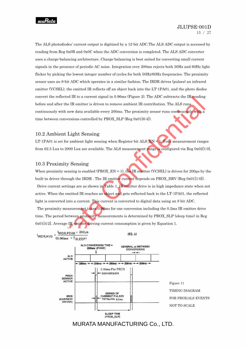
10.3 Proximity Sensing
When proximity sensing is enabled (PROX_EN = 1), the IR emitter (VCSEL) is driven for 200μs by the
built-in driver through the IRDR . The IR emitter current depends on PROX_DRV (Reg 0x01[1:0]).
Drive current settings are as shown in Table 1. IR emitter drive is in high impedance state when not
active. When the emitted IR reaches an object and gets reflected back to the LT-1PA01, the reflected
light is converted into a current. This current is converted to digital data using an 8 bit ADC.
The proximity measurement takes 0.96ms for one conversion including the 0.2ms IR emitter drive
time. The period between proximity measurements is determined by PROX_SLP (sleep time) in Reg
0x01[4:2]. Average IR emitter driving current consumption is given by Equation 1.
Figure 11
TIMING DIAGRAM
FOR PROX/ALS EVENTS
NOT TO SCALE
JLUPSE-001D
16 / 27
MURATA MANUFACTURING Co., LTD.
10.4 Total Current Consumption
Total current consumption is the sum of IDD and IIRDR. The IRDR pin sinks current and the average
IRDR current is calculated using Equation 1. IDD depends on voltage and the mode-ofoperation.
For simplicity Equation 1 ignores proximity ADC conversion time since it is much smaller than the
sleep time.
10.5 ALS IR Compensation
LT-1PA01 is designed for operation under dark glass cover. Glass or plastic covers can significantly
attenuate visible light and pass the Infrared light without much attenuation. Consequently the
LT-1PA01 under a glass cover experiences an (undesirable) IR rich environment. The on-chip ALS
passive optical filter on LT-1PA01 is designed to block most of the IR incident on the ALS photo
diodes. In addition, LT-1PA01 provides a programmable active IR compensation that subtracts
residual IR still reaching the sensor. The ALS_IR_COMP register (Reg 0x03[4:0]) allows fine tuning of
the residual infrared component from the ALS output. The recommended procedure for determining
ALS IR compensation is as follows:
• Illuminate LT-1PA01 based product with a light source without IR, such as a white LED.
Record the ALS measurement and the Lux level.
• Illuminate the device with an IR LED and the White LED. Take an ALS measurement and
Lux level measurement.
• Adjust the ALS_IR_COMP register (Reg 0x03, bits 4:0) to compensate for the IR contribution.
• Repeat steps above until the IR light source contribution to the ALS measurement is under 10
percent assuming no change in Lux level due to IR light source.
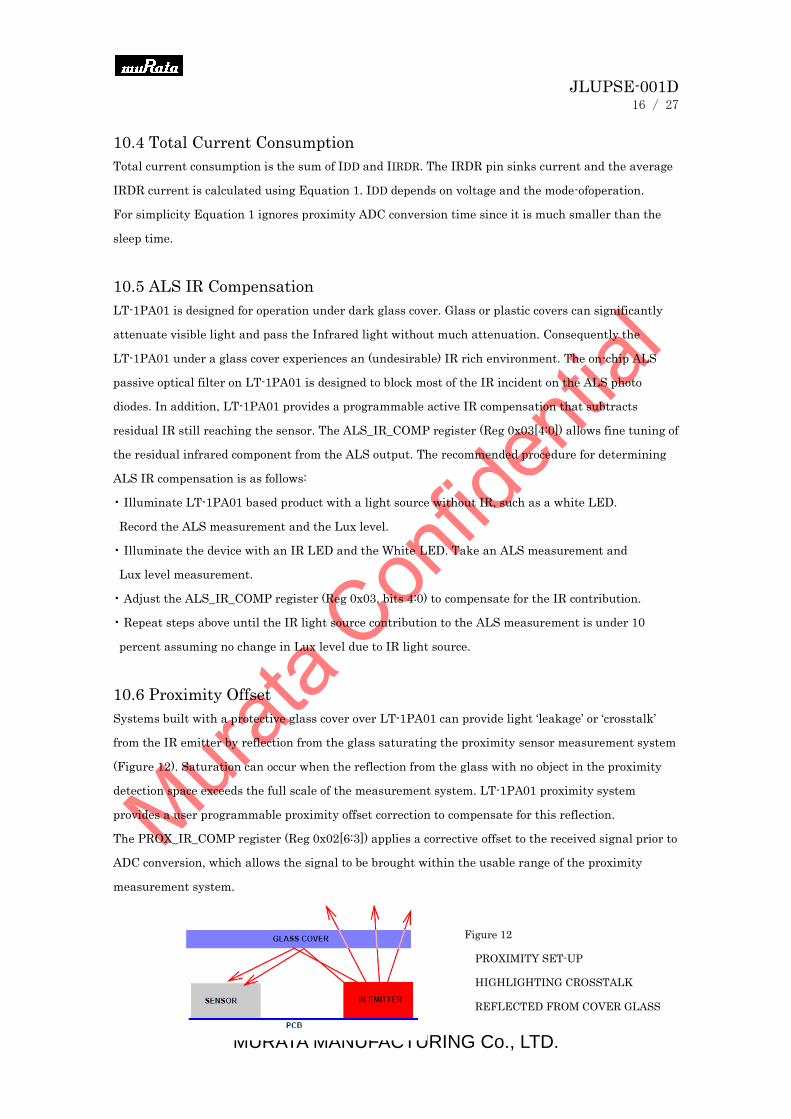
10.6 Proximity Offset
Systems built with a protective glass cover over LT-1PA01 can provide light ‘leakage’ or ‘crosstalk’
from the IR emitter by reflection from the glass saturating the proximity sensor measurement system
(Figure 12). Saturation can occur when the reflection from the glass with no object in the proximity
detection space exceeds the full scale of the measurement system. LT-1PA01 proximity system
provides a user programmable proximity offset correction to compensate for this reflection.
The PROX_IR_COMP register (Reg 0x02[6:3]) applies a corrective offset to the received signal prior to
ADC conversion, which allows the signal to be brought within the usable range of the proximity
measurement system.
Figure 12
PROXIMITY SET-UP
HIGHLIGHTING CROSSTALK
REFLECTED FROM COVER GLASS

JLUPSE-001D
17 / 27
MURATA MANUFACTURING Co., LTD.
10.7 Proximity Ambient Washout Detection
The optical proximity sensor can be saturated when illuminated with excessive ambient light. The
LT-1PA01 provides a warning flag when the proximity measurement may be erroneous due to
excessive ambient light. The PROX_WASH register (Reg 0x0D[0]) reports this condition.
10.8 Interrupts Events
LT-1PA01 interrupts are designed to minimize host micro-controller overhead of continuous polling.
LT-1PA01 can generate interrupts on the results of an ALS measurement or proximity measurement.
The ALS interrupt event ALS_FLAG (Reg 0x04[3]) is governed by Reg 0x07 through 0x09. Two 12 bit
high and low threshold values are written to these registers. LT-1PA01 will set the ALS interrupt flag
if the ADC conversion count in Registers 0x0B and 0x0C are outside the programmed thresholds. The
ALS_FLAG is cleared by writing a ‘0’ to Reg 0x04[3]. A proximity interrupt event (PROX_FLAG) is
governed by the high and low thresholds in Reg 0x05 and 0x06 (PROX_LT and PROX_HT) and is
indicated by Reg 0x04[7]. PROX_FLAG is set when the measured proximity data is more than the
higher threshold. The proximity interrupt flag is cleared when the prox data is lower than the low
proximity threshold or by writing a ‘0’ to Reg 0x04[7].
The Proximity interrupt generation can be selected between ‘out-of-window’ threshold and hysteresis
schemes. When the PROX_INT_ALG register (Reg 0x02, Bit 7) is set to 0, proximity uses a window
comparator scheme; when set to 1, proximity uses a hysteresis scheme. In hysteresis mode, the
interrupt event is generated if the proximity ADC count is higher than the PROX_HT threshold and
the interrupt event is cleared when the proximity ADC count is less than the PROX_LT threshold. The
interrupt event flag can also be cleared by writing a ‘0’ to Reg 0x04[7].
10.9 Interrupt Persistence
To minimize interrupt events due to ‘transient’ conditions an interrupt persistency option is available
for both ALS and proximity measurements. Persistency requires ‘X-consecutive’ interrupt flags before
the INT pin is driven low. Both ALS and PROX have their own independent interrupt persistency
options. ALS_PRST and PROX_PRST configuration is controlled from Reg 0x04.
10.10 Power-Up and ‘Brown-Out’ Reset
LT-1PA01 has an enhanced power-on-reset system. A ‘Brown-Out’ detector flag in Reg 0x04[4] informs
the system that the device has powered-up properly. This flag should be reset as part of initialization
sequence. A ‘Brown-out’ condition is defined as an operating condition when the power supply voltage
is not within the specified limits. During the brown-out period at power-up, the I2C interface and the
IR emitter driver are inactive. Following brown-out, the I2C interface is re-initialized and the
configuration registers are set to power-up default values. After power-up and during device
initialization host should examine that the PWR_FAIL flag (Reg 0x04[4]) is set and then clear the flag

JLUPSE-001D
18 / 27
MURATA MANUFACTURING Co., LTD.
by writing ‘0’ to Reg 0x04[4]. Following power-up, a ‘Brown-Out’ condition, if detected, is reported by
PWR_FAIL flag by Reg 0x04[4]. Device configuration registers are not set to their power-up default
after ‘Brown-Out’. PWR_FAIL flag should be periodically monitored to detect post power-up power
supply interruption.
10.11 Power-Down
Setting ALS_EN (Reg 0x02[2]) and PROX_EN (Reg 0x01[5]) to ‘0’ puts the LT-1PA01 into a
power-down state with power supplycurrent dropping to less than 1μA. All configuration register are
maintained in power-down mode.
10.12 Soft Reset
A software reset to LT-1PA01 can be initiated by writing 0x38 to Reg 0x0E. Following reset, all
configuration registers are set to their default power-up state. LT-1PA01 after soft reset defaults
to the power-down configuration.
10.13 ALS Data Count Read Out
A 2 byte I2C read from ALS_DATA_HB outputs MSB 1st data on SDA. This data is LSB justified with
a zero fill for unused bits. Note that the MSB byte address precedes the LSB byte address. The
ALS count is 256*(ALS_DATA_HB) + ALS_DATA_LB.
10.14 Proximity Detection of Various Objects
Proximity sensing relies on the amount of IR reflected back from objects. A perfect black object would
absorb all incident light and reflect no photons. The LT-1PA01 is sensitive enough to detect black ESD
foam which reflects only 1% of IR. Blonde hair typically reflects more than brown hair and skin tissue
is more reflective than human hair. IR penetrates into the skin and is reflected from within. As a
result, the proximity count generally peaks at contact and monotonically decreases as skin moves
away. The reflective characteristics of skin are very different from that of an inanimate object such as
paper.
JLUPSE-001D
19 / 27
MURATA MANUFACTURING Co., LTD.
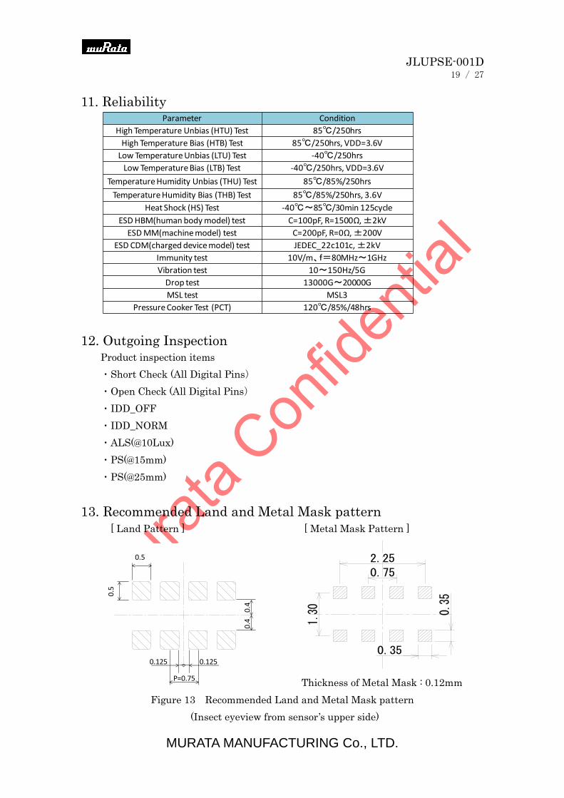
11. Reliability
12. Outgoing Inspection
Product inspection items
・Short Check (All Digital Pins)
・Open Check (All Digital Pins)
・IDD_OFF
・IDD_NORM
・ALS(@10Lux)
・PS(@15mm)
・PS(@25mm)
13. Recommended Land and Metal Mask pattern
[ Land Pattern ] [ Metal Mask Pattern ]
Thickness of Metal Mask : 0.12mm
Figure 13 Recommended Land and Metal Mask pattern
(Insect eyeview from sensor’s upper side)
0.5
0.1250.125
P=0.75
0.5
0.4
0.4
Parameter Condition
High Temperature Unbias (HTU) Test 85℃/250hrs
High Temperature Bias (HTB) Test 85℃/250hrs, VDD=3.6V
Low Temperature Unbias (LTU) Test -40℃/250hrs
Low Temperature Bias (LTB) Test -40℃/250hrs, VDD=3.6V
Temperature Humidity Unbias (THU) Test 85℃/85%/250hrs
Temperature Humidity Bias (THB) Test 85℃/85%/250hrs, 3.6V
Heat Shock (HS) Test -40℃~85℃/30min 125cycle
ESD HBM(human body model) test C=100pF, R=1500Ω, ±2kV
ESD MM(machine model) test C=200pF, R=0Ω, ±200V
ESD CDM(charged device model) test JEDEC_22c101c, ±2kV
Immunity test 10V/m、f=80MHz~1GHz
Vibration test 10~150Hz/5G
Drop test 13000G~20000G
MSL test MSL3
Pressure Cooker Test (PCT) 120℃/85%/48hrs
JLUPSE-001D
20 / 27
MURATA MANUFACTURING Co., LTD.
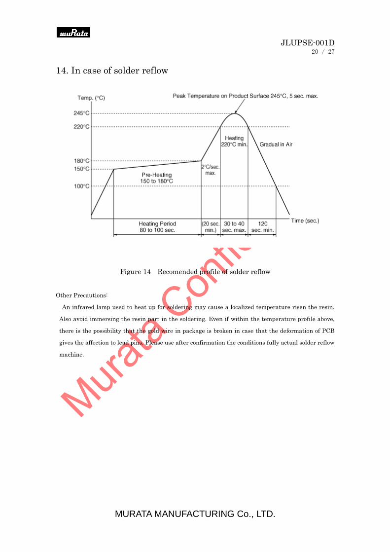
14. In case of solder reflow
Figure 14 Recomended profile of solder reflow
Other Precautions:
An infrared lamp used to heat up for soldering may cause a localized temperature risen the resin.
Also avoid immersing the resin part in the soldering. Even if within the temperature profile above,
there is the possibility that the gold wire in package is broken in case that the deformation of PCB
gives the affection to lead pins. Please use after confirmation the conditions fully actual solder reflow
machine.
JLUPSE-001D
21 / 27
MURATA MANUFACTURING Co., LTD.
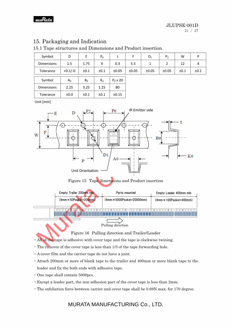
15. Packaging and Indication
15.1 Tape structures and Dimensions and Product insertion
Figure 15 Tape dimensions and Product insertion
Pulling direction
Figure 16 Pulling direction and Trailer/Leader
・All of the tape is adhesive with cover tape and the tape is clockwise twining.
・The runover of the cover tape is less than 1/3 of the tape forwarding hole.
・A cover film and the carrier tape do not have a joint.
・Attach 200mm or more of blank tape to the trailer and 400mm or more blank tape to the
leader and fix the both ends with adhesive tape.
・One tape shall contain 5000pcs.
・Except a leader part, the non-adhesion part of the cover tape is less than 2mm.
・The exfoliation force between carrier and cover tape shall be 0.69N max. for 170 degree.
Empty Leader 400mm min
(4mm×100Pocket=400mm)
Parts mounted
(4mm×5000Pocket=20000mm)
Empty Trailer 200mm min
(4mm×50Pocket=200mm)
Symbol D E P0 t F D1 P2 W P
Dimensions 1.5 1.75 4 0.3 5.5 1 2 12 4
Tolerance +0.1/-0 ±0.1 ±0.1 ±0.05 ±0.05 ±0.05 ±0.05 ±0.1 ±0.1
Symbol A0 B0 K0 P0 x 20
Dimensions 2.25 3.25 1.25 80
Tolerance ±0.0 ±0.1 ±0.1 ±0.15
Unit [mm]
IR Emitter side
Unit Orientation
JLUPSE-001D
22 / 27
MURATA MANUFACTURING Co., LTD.
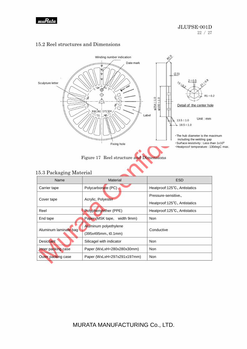
15.2 Reel structures and Dimensions
Figure 17 Reel structure and Dimensions
15.3 Packaging Material
Name Material ESD
Carrier tape Polycarbonate (PC) Heatproof:125℃、Antistatics
Cover tape Acrylic, Polyester Pressure-sensitive、
Heatproof:125℃、Antistatics
Reel Polyphenylether (PPE) Heatproof:125℃、Antistatics
End tape Paper (MSK tape, width 9mm) Non
Aluminum laminate bag Aluminum polyethylene
(395x495mm、t0.1mm) Conductive
Desiccant Silicagel with indicator Non
Inner packing case Paper (WxLxH=280x280x30mm) Non
Outer packing case Paper (WxLxH=297x291x197mm) Non
Fixing hole
Label
Date mark
Winding number indication
Sculpture letter
φ2
54±
1.0
φ1
00±
1.0
13.5±1.0
18.5±1.0
Detail of the center hole
2±0.5
R1±0.2
・The hub diameter is the maximum
including the welding gap
・Surface resistivity : Less than 1x10⁹
・Heatproof temperature : 130degC max.
(2.5)
Unit : mm

JLUPSE-001D
23 / 27
MURATA MANUFACTURING Co., LTD.
15.4 Packing and Shipping Label
1) Shipping Label Dimension : 75×35 mm
2) Inner packing
3) Outer Packing
Inner Packing case Dimension (Inside) : 280×280×30 mm
TYPE:ABC
ABCdef gh i j k l mnop
Q'TY:5000 5 0 0 0
KeyNo:123456 1 2 3 4 5 6
SEALED:20131122 2 0 1 3 1 1 2 2
Shipping Label
Silicagel with indicator Heat Sealing
Aluminum laminated sack
カートン (蓋)
Inner Package case
Shipping Label
Fixed with tape
Shipping Label
Shipping Label Aluminum laminated sack
JLUPSE-001D
24 / 27
MURATA MANUFACTURING Co., LTD.
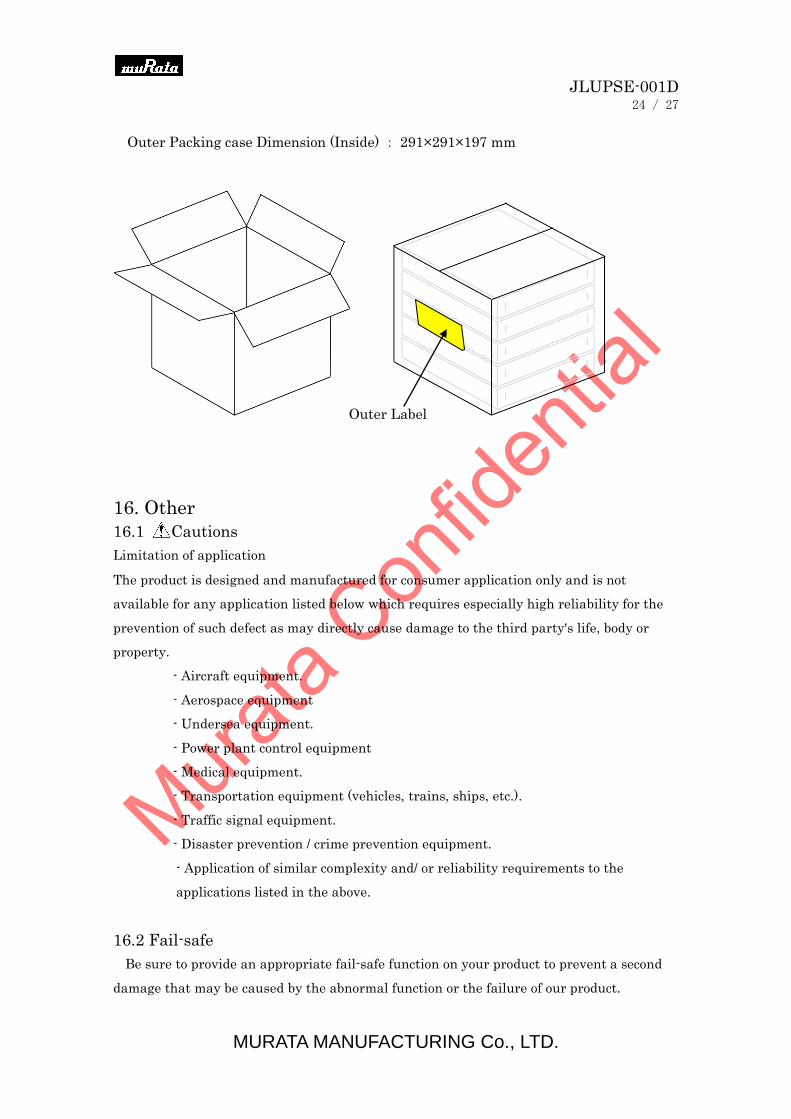
Outer Packing case Dimension (Inside) : 291×291×197 mm
16. Other
16.1 Cautions
Limitation of application
The product is designed and manufactured for consumer application only and is not
available for any application listed below which requires especially high reliability for the
prevention of such defect as may directly cause damage to the third party's life, body or
property.
- Aircraft equipment.
- Aerospace equipment
- Undersea equipment.
- Power plant control equipment
- Medical equipment.
- Transportation equipment (vehicles, trains, ships, etc.).
- Traffic signal equipment.
- Disaster prevention / crime prevention equipment.
- Application of similar complexity and/ or reliability requirements to the
applications listed in the above.
16.2 Fail-safe
Be sure to provide an appropriate fail-safe function on your product to prevent a second
damage that may be caused by the abnormal function or the failure of our product.
Outer Label

JLUPSE-001D
25 / 27
MURATA MANUFACTURING Co., LTD.
16.3 Precautions for use
Notice in design
1) In the case of outdoor use, suitable optical filter and water and humidity proof structure
should be applied.
2) To prevent failure or malfunction, please use a stabilized power supply.
3) Please avoid using the sensor in the following conditions because it may cause failure or
malfunction ;
a) In such a fluid as water, alcohol etc. corrosive gas (S02, Cl2, NOX etc.) or
sea breeze.
b) In high humidity.
c) In a place exposed directly to sunlight or headlight of automobile.
d) In a place exposed to rapid ambient temperature change.
e) In a place exposed directly to blow from air-conditioner or heater.
f) In a place exposed to strong vibration.
g) In a place exposed to strong electromagnetic field.
h) In such a place where infrared ray is shaded.
i) In any other place similar to the above (a) through (h).
16.4 Notice in handling and storage
1) Optical lens and light receiving area of sensor should not be scratched or soiled.
2) Strong shock should be avoided.
3) Electrostatics and strong electromagnetic field should be avoided.
4) High temperature, high humidity, fluid as water or alcohol etc., corrosive gas ( S02, Cl2,
NOX etc.) and sea breeze should be avoided.
5) The delivered product should be stored with the conditions as follows and in dry box or
N2 atmosphere, and the warranty term for the shipped product shall be for 6 months
after shipping to the designated place by the order customer.
Storage temperature : 15 to 35℃、Humidity : below 70%RH
6) Regarding treatment after unsealed, devices should be mounted under the temperature
condition of 5 to30℃, at the humidity condition of below 60%RH, within 168 hours and
in case that long term storage is needed, devices should either be stored in dry box or
resealed to moist-proof bag with siccative and leave them in the environment where the
temperature is 15 to 30℃, at humidity condition of below 70%RH, and devices must be
mounted within 1 weeks.

JLUPSE-001D
26 / 27
MURATA MANUFACTURING Co., LTD.
7) Regarding baking before mounting, in the event that the devices are not maintained in
the storage conditions described above, baking must be applied before devices are not
mounted. The case that LT-1PA01 was not mounted under the temperature condition of
15 to 30℃, at humidity condition of below 70%RH within 168 hours after 1st time
reflow, baking process must be applied before 2nd time reflow. And also please note that
baking should only be applied twice.
Recommended condition of the devices baking and reel baking : 100℃, 4 hours
**To complete the baking properly, devices should be placed to the metal tray.
And also in the case of reel baking, hung the reel in the oven by passing the shaft in
the center hole of reel and please avoid laying the reel.
16.5 Notice (soldering and mounting)
1. Please follow soldering conditions described in the specification. This product can
permanently stop operating if the optical characteristic is decreased due to excessive
heating.
2. Cleaning after reflow soldering should not be applied. Optical lens and light receiving
area of sensor should not be soiled because it may cause failure or malfunction.
3. As electrostatic field or discharge may degrade this product, please take methods such
as wearing wrist strap, grounding working desk or equipment to avoid this damage.

JLUPSE-001D
27 / 27
MURATA MANUFACTURING Co., LTD.
17. Notice
1. Murata Manufacturing Co., Ltd.(Murata) reserves the right to make changes to the
products contained in this document to improve performance or for any other purpose,
or to discontinue them without notice. Customers are advised to contact Murata
to obtain the latest product information before placing orders or designing Murata
products into systems and make sure that your product has been evaluated in view of
your specifications with our product being mounted to your product.
2. You are requested not to use our product deviating from the agreed specifications.
3. Murata consider it not to appropriate to include any terms and conditions with regard
to the business transaction in the product specifications, drawings or other technical
documents. Therefore, if your technical documents as above include such terms and
conditions such as warranty clause, product liability clause, or intellectual property
infringement liability clause, they will be deemed to be invalid.
4. Murata assumes no responsibility for the use of any products or circuits described in
this document or customer product design, conveys no license, either expressed or
implied, under any patent or other right, and makes no representation that
the circuits are free of patent infringement. Murata further makes no claim as to
the suitability of its products for any particular purpose, nor does Murata assume
any liability arising out of the use of any product or circuit, and specifically disclaims
any and all liability, including without limitation consequential or incidental
damages.
5. Laser Safety Considerations
The LT-1PA01 is designed and tested to enable manufacturers to achieve eye safety
certification with minimal effort. This sensor complies with the Class 1 emission
requirements of FDA 21CFR Part 1040.10 and IEC60825-1.
When installed and operated in accordance with all requirements in this sheet,
the LT-1PA01 satisfies FDA 21CFR Part 1040.10 and IEC60825-1 Class1.
6. MURATA MANUFACTURING CO., LTD. PRODUCTS ARE NOT DESIGNED OR
INTENDED FOR USE IN CRITICAL APPLICATIONS IN WHICH THE FAILURE
OR MALFUNCTION OF THE TAOS PRODUCT MAY RESULT IN PERSONAL
INJURY OR DEATH. USE OF MURATA PRODUCTS IN LIFE SUPPORT SYSTEMS
IS EXPRESSLY UNAUTHORIZED AND ANY SUCH USE BY A CUSTOMER IS
COMPLETELY AT THE CUSTOMER’S RISK.
Mouser Electronics
Authorized Distributor
Click to View Pricing, Inventory, Delivery & Lifecycle Information: Murata:
LT-1PA01