Embed Size (px)
Citation preview

Protocoles et Interconnexions
Course Overview and Introduction Dario Vieira Department of Computer Science EFREI

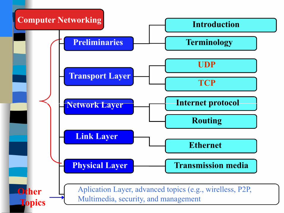
Computer Networking
Preliminaries
Transport Layer
Network Layer
Link Layer
Physical Layer Transmission media
Ethernet
Routing
Internet protocol
TCP
UDP
Terminology
Introduction
Aplication Layer, advanced topics (e.g., wirelless, P2P, Multimedia, security, and management
Other Topics

CN5E by Tanenbaum & Wetherall, © Pearson Education-Prentice Hall and D. Wetherall, 2011
Network Software
– Protocol layers » – Design issues for the layers » – Connection-oriented vs. connectionless service
» – Service primitives » – Relationship of services to protocols »

What’s a protocol? human protocols: v “what’s the time?” v “I have a question” v introductions
… specific msgs sent … specific actions taken
when msgs received, or other events
network protocols: v machines rather than
humans v all communication
activity in Internet governed by protocols
protocols define format, order of msgs sent and received among network
entities, and actions taken on msg
transmission, receipt Introduction 1-4

What’s a protocol?
A human protocol and a computer network protocol:
Hi
Hi Got the time? 2:00
TCP connection response
Get http://www.awl.com/kurose-ross
<file> time
Introduction 1-5
TCP connection request

CN5E by Tanenbaum & Wetherall, © Pearson Education-Prentice Hall and D. Wetherall, 2011
Protocol Layers (1) ■ Protocol layering is the main structuring method used to divide up
network functionality.
• Each protocol instance talks virtually to its peer
• Each layer communicates only by using the one below
• Lower layer services are accessed by an interface
• At bottom, messages are carried by the medium

CN5E by Tanenbaum & Wetherall, © Pearson Education-Prentice Hall and D. Wetherall, 2011
Protocol Layers (2) ■ Example: the philosopher-translator-secretary architecture ■ Each protocol at different layers serves a different purpose
CN5E by Tanenbaum & Wetherall, © Pearson Education-Prentice Hall and D. Wetherall, 2011
Protocol Layers (3) ■ Each lower layer adds its own header (with control information) to the
message to transmit and removes it on receive
■ Layers may also split and join messages, etc.

CN5E by Tanenbaum & Wetherall, © Pearson Education-Prentice Hall and D. Wetherall, 2011
Design Issues for the Layers ■ Each layer solves a particular problem but must include
mechanisms to address a set of recurring design issues
Issue Example mechanisms at different layers Reliability despite failures
Codes for error detection/correction Routing around failures
Network growth and evolution
Addressing and naming Protocol layering
Allocation of resources like bandwidth
Multiple access Congestion control
Security against various threats
Confidentiality of messages Authentication of communicating parties

CN5E by Tanenbaum & Wetherall, © Pearson Education-Prentice Hall and D. Wetherall, 2011
Connection-Oriented vs. Connectionless ■ Service provided by a layer may be kinds of either:
– Connection-oriented, must be set up for ongoing use (and torn down after use), e.g., phone call
– Connectionless, messages are handled separately, e.g., postal delivery

Connection-Oriented
• In connection-oriented communication, 2 communication partners (peers A and B) first establish a logical point-to-point relationship (=connection) with each other.
• After establishing the connection, all traffic injected into either endpoint is delivered to the other endpoint and peer.
• The network inbetween is often unaware of connections. The routers, switches etc. in the network forward traffic on a packet-by-packet basis without considering connections.
Peer A Peer B
Connection endpoint
Connection endpoint
Packet
Logical connection
Packet Packet
© Peter R. Egli 2015
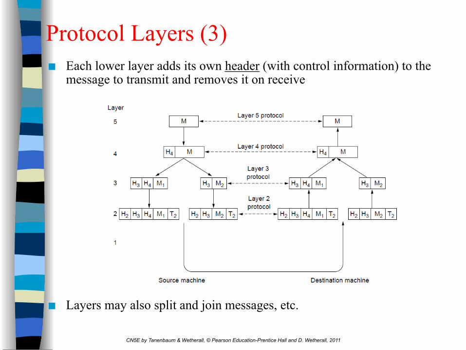
Connection-Oriented vs. Connectionless
Connection-less: A connection-less protocol allows a peer A to send messages to different peers (B…D) without first establishing a logical connection.
Analogy with old-style communication: 1. Connection-oriented communication can be
compared with good old telephony service.
2. Connection-less communication resembles postal correspondence.
Peer A
Peer B
Peer C
Peer D
© Peter R. Egli 2015
Connection-Oriented vs. Connectionless

CN5E by Tanenbaum & Wetherall, © Pearson Education-Prentice Hall and D. Wetherall, 2011
Service Primitives (1) ■ A service is provided to the layer above as primitives ■ Hypothetical example of service primitives that may provide a reliable
byte stream (connection-oriented) service:

CN5E by Tanenbaum & Wetherall, © Pearson Education-Prentice Hall and D. Wetherall, 2011
Service Primitives (2) ■ Hypothetical example of how these primitives may be used for a client-server
interaction
Client Server
LISTEN (0)
ACCEPT RECEIVE
SEND (4)
DISCONNECT (6)
CONNECT (1)
SEND RECEIVE
DISCONNECT (5)
Connect request
Accept response Request for data
Reply Disconnect
Disconnect
(2)
(3)

CN5E by Tanenbaum & Wetherall, © Pearson Education-Prentice Hall and D. Wetherall, 2011
Relationship of Services to Protocols ■ Recap:
– A layer provides a service to the one above [vertical] – A layer talks to its peer using a protocol [horizontal]

Unicast, broadcast and multicast define the packet delivery mode, i.e. if packets are delivered
• to a single destination (unicast), • to a group of destinations (multicast) or • to all possible destinations in a network (broadcast)
In anycast routing, the network delivers packets to the topologically nearest destination to reduce latency and network load.
Unicast Broadcast
Multicast Anycast
© Peter R. Egli 2015
Unicast, Broadcast, Multicast, Anycast

A receiver signals successful reception of a packet (message) by sending back an acknowledgment packet to the sender. Acknowledgments may have different meanings such as:
a) Message was successfully received, will be processed by receiver b) Message contents was accepted, will be processed by receiver c) Message was successfully received and processed d) Message was received but some error occurred (negative acknowledgment)
Typically, acknowledgments are used for signaling successful reception so that the sender protocol layer can free resources such as transmit buffers that are used for retransmissions. Sender Receiver
© Peter R. Egli 2015
Acknowledged Data Transfer
Acknowledge (ID=1)
Message (ID=1)
Acknowledge (ID=2)
Message (ID=2)

Handshake is a procedure employed by two peers to synchronize and exchange information needed in the subsequent communication. A handshake is typically a threeway packet exchange initiated by one peer.
1. Peer B accepts the information sent by peer A (Peer-A-ID in the example below)
2. And sends back an acknowledgment along with its own ID (Peer-B-ID)
3. Finally, peer A acknowledges peer B's ID by returning an acknowlegment.
Peer-A-ID = 1
Ack Peer-A-ID,
Peer-B-ID = 2 Ack
Peer-B-ID
Peer A Peer B
© Peter R. Egli 2015
Handshake

Dictated by the application logic, communication partners may have different roles from which the following communication patterns can be derived. Client-server (C/S): In the C/S model, application logic is distributed with a centralized server component responding to requests from clients (functional asymmetry). The client is the initiator of a connection / session (typically TCP) to the server which acts as a hub connecting multiple clients. Clients do not directly communicate with each other. Example C/S: Browser (C) and web server (S).
Client B
Server
Client A
Client C
© Peter R. Egli 2015
Client-Server, Peer-to-Peer (1/2)

In the P2P model, all peers have the same functionality and communicate directly with each other. Each peer can initiate a connection / session to any other peer. There is no central component Therefore this model is resilient against failures of individual peers. Network and computing load is distributed more evenly compared to the centralized C/S model. Example: File sharing platform.
Peer B
Peer D
Peer A
Peer C
© Peter R. Egli 2015
Client-Server, Peer-to-Peer (2/2)

CN5E by Tanenbaum & Wetherall, © Pearson Education-Prentice Hall and D. Wetherall, 2011
Reference Models ■ Reference models describe the layers in a network
architecture
– OSI reference model » – TCP/IP reference model » – Model used for this text » – Critique of OSI and TCP/IP »

CN5E by Tanenbaum & Wetherall, © Pearson Education-Prentice Hall and D. Wetherall, 2011
OSI Reference Model ■ A principled, international standard, seven layer model to connect different
systems
– Provides functions needed by users
– Converts different representations
– Manages task dialogs
– Provides end-to-end delivery
– Sends packets over multiple links
– Sends frames of information
– Sends bits as signals

The OSI Protocol Model
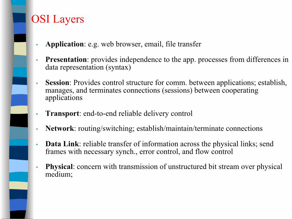
OSI Layers
• Application: e.g. web browser, email, file transfer
• Presentation: provides independence to the app. processes from differences in data representation (syntax)
• Session: Provides control structure for comm. between applications; establish, manages, and terminates connections (sessions) between cooperating applications
• Transport: end-to-end reliable delivery control
• Network: routing/switching; establish/maintain/terminate connections
• Data Link: reliable transfer of information across the physical links; send frames with necessary synch., error control, and flow control
• Physical: concern with transmission of unstructured bit stream over physical medium;
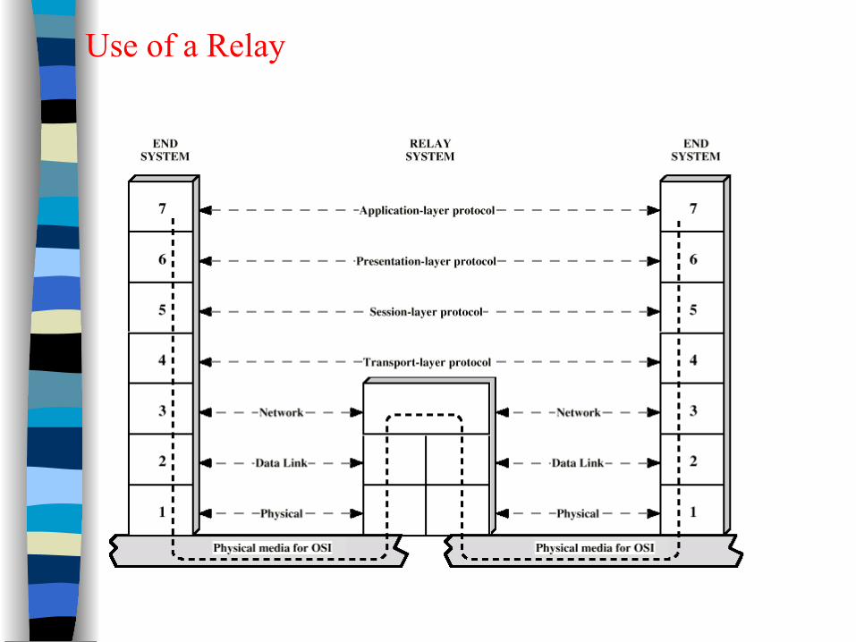
Use of a Relay
CN5E by Tanenbaum & Wetherall, © Pearson Education-Prentice Hall and D. Wetherall, 2011
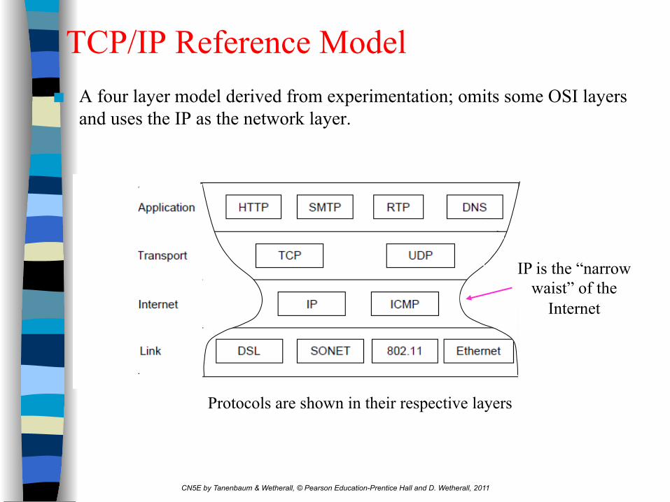
TCP/IP Reference Model ■ A four layer model derived from experimentation; omits some OSI layers
and uses the IP as the network layer.
IP is the “narrow waist” of the
Internet
Protocols are shown in their respective layers

TCP/IP Protocol Architecture
• Developed by the US Defense Advanced Research Project Agency (DARPA) for its packet switched network (ARPANET)
• Used by the global Internet
• No official model but a working one. ➢ Application layer: logic needed to support various user applications
➢ Host to host or transport layer: reliable end-to-end delivery mechanisms, e.g. TCP
➢ Internet layer: provide routing function across multiple networks
➢ Network access layer: concern the exchange of date between end system & the network to which it is attached
➢ Physical layer: Physical interface between a data trans. device & a trans. medium or network

TCP/IP Protocol Architecture Model

PDUs in TCP/IP Architecture

Some Protocols in TCP/IP Suite

OSI v TCP/IP
CN5E by Tanenbaum & Wetherall, © Pearson Education-Prentice Hall and D. Wetherall, 2011
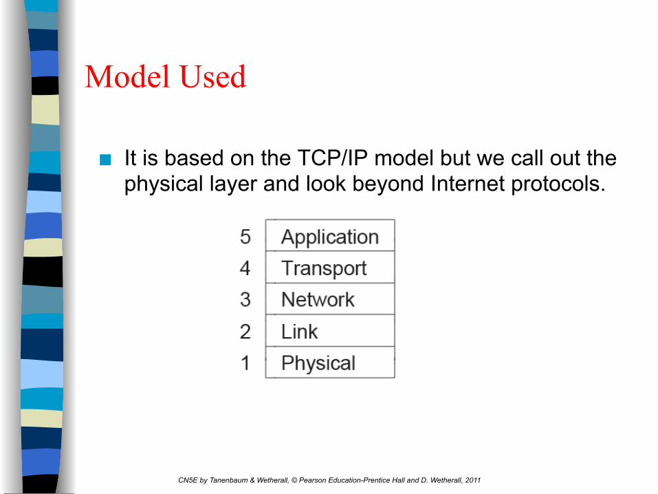
Model Used
■ It is based on the TCP/IP model but we call out the physical layer and look beyond Internet protocols.
CN5E by Tanenbaum & Wetherall, © Pearson Education-Prentice Hall and D. Wetherall, 2011
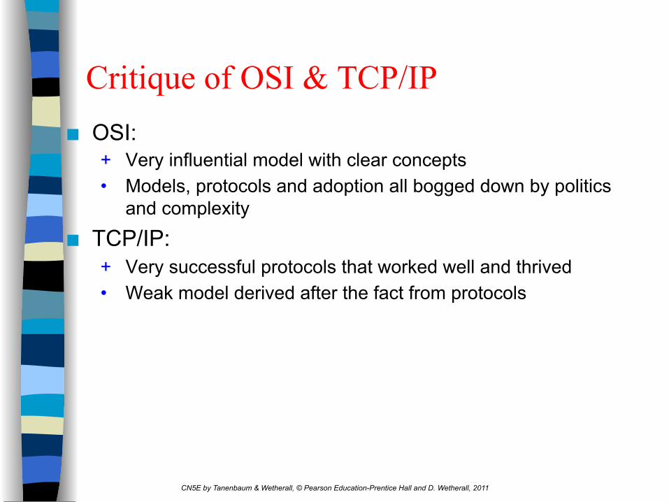
Critique of OSI & TCP/IP ■ OSI:
+ Very influential model with clear concepts • Models, protocols and adoption all bogged down by politics
and complexity
■ TCP/IP: + Very successful protocols that worked well and thrived • Weak model derived after the fact from protocols
Computer Networking
Preliminaries
Transport Layer
Network Layer
Link Layer
Physical Layer Transmission media
Ethernet
Routing
Internet protocol
TCP
UDP
Terminology
Introduction
Aplication Layer, advanced topics (e.g., wirelless, P2P, Multimedia, security, and management
Other Topics

Transport Layer 3-35
Chapter 3 Transport Layer
Computer Networking: A Top Down Approach 5th edition. Jim Kurose, Keith Ross Addison-Wesley, April 2009.

Transport Layer 3-36
Chapter 3: Transport Layer ■ Our Goals
v Learn about transport layer protocols in the Internet
• UDP: connectionless transport • TCP: connection-oriented transport
Application
Transport
Network
Link
Physical
Transport

Transport Layer 3-37
Transport services and protocols ■ Transport protocols run in end
systems – send side: breaks app
messages into segments, passes to network layer
– rcv side: reassembles segments into messages, passes to app layer
■ More than one transport protocol available to apps – Internet: TCP and UDP
application transport network data link physical
application transport network data link physical

Transport Layer 3-38
Transport vs. Network layer
■ Network layer – Logical communication
between hosts
■ Transport layer – Logical communication
between processes – Relies on, enhances,
network layer services
application transport network data link physical
application transport network data link physical

Transport Layer 3-39
Internet Transport-layer Protocols ■ Reliable, in-order delivery
(TCP) – congestion control – flow control – connection setup
■ Unreliable, unordered delivery (UDP) – no-frills extension of “best-effort” IP
■ Services not available – delay guarantees – bandwidth guarantees
application transport network data link physical
network data link physical
network data link physical
network data link physical
network data link physical
network data link physical
network data link physical
application transport network data link physical

Transport Layer 3-40
Chapter 3 outline 3.1 Transport-layer services
3.2 Connectionless Transport: UDP
3.3 Principles of reliable data transfer
3.4 Connection-oriented transport: TCP
3.5 Principles of congestion control
3.6 TCP congestion control

Transport Layer 3-41
UDP: User Datagram Protocol [RFC 768] ■ “No frills,” “bare bones”
Internet transport protocol
■ “Best effort” service, UDP segments may be: – lost – delivered out of order to
app
■ Connectionless – No handshaking between
UDP sender, receiver – Each UDP segment
handled independently of others
Why is there a UDP? ■ No connection establishment
(which can add delay)
■ Simple: no connection state at sender, receiver
■ Small segment header
■ No congestion control: UDP can blast away as fast as desired

Transport Layer 3-42
UDP: more ■ Often used for
streaming multimedia apps – loss tolerant – rate sensitive
■ Other UDP uses – DNS – SNMP
■ Reliable transfer over UDP: add reliability at application layer – application-specific error
recovery!
source port # dest port #
32 bits
Application data (message)
UDP segment format
length checksum
Length, in bytes of UDP segment, including header

Transport Layer 3-43
Chapter 3 outline 3.1 Transport-layer services
3.2 Connectionless Transport: UDP
3.3 Principles of reliable data transfer
3.4 Connection-oriented transport: TCP
3.5 Principles of congestion control
3.6 TCP congestion control

Transport Layer 3-44
Principles of Reliable Data Transfer ■ Important in app., transport, link layers
– top-10 list of important networking topics!

Transport Layer 3-45
Principles of Reliable Data Transfer
■ Characteristics of unreliable channel will determine complexity of reliable data transfer protocol
■ Important in app., transport, link layers – top-10 list of important networking topics!

Transport Layer 3-46
Principles of Reliable Data Transfer
■ Characteristics of unreliable channel will determine complexity of reliable data transfer protocol (rdt)
■ Important in app., transport, link layers – top-10 list of important networking topics!

Transport Layer 3-47
Reliable Data Transfer: Getting Started
send side
receive side
rdt_send(): called from above, (e.g., by app.). Passed data to deliver to receiver upper layer
udt_send(): called by rdt, to transfer packet over unreliable channel to receiver
rdt_rcv(): called when packet arrives on rcv-side of channel
deliver_data(): called by rdt to deliver data to upper

Transport Layer 3-48
Reliable Data Transfer: Getting Started
■ Incrementally develop sender, receiver sides of
Reliable Data Transfer protocol (rdt)
■ Consider only unidirectional data transfer – but control info will flow on both directions!
■ Use Finite State Machines (FSM) to specify sender, receiver
State 1 State 2
event causing state transition actions taken on state transition
state: when in this “state” next state
uniquely determined by next
event
event actions

Transport Layer 3-49
Rdt1.0: Reliable Transfer over a Reliable Channel ■ Underlying channel perfectly reliable
– no bit errors – no loss of packets
■ Separate FSMs for sender, receiver – sender sends data into underlying channel – receiver read data from underlying channel
Wait for call from above packet =make_pkt(data)
udt_send(packet)
rdt_send(data) Extract (packet,data) deliver_data(data)
Wait for call from below
rdt_rcv(packet)
sender receiver

Transport Layer 3-50
Rdt2.0: channel with bit errors
■ Underlying channel may flip bits in packet – checksum to detect bit errors
■ The question: how to recover from errors? – acknowledgements (ACKs): receiver explicitly tells sender
that pkt received OK – negative acknowledgements (NAKs): receiver explicitly tells
sender that pkt had errors – sender retransmits pkt on receipt of NAK
■ new mechanisms in rdt2.0 (beyond rdt1.0): – error detection – receiver feedback: control msgs (ACK,NAK) rcvr->sender
How do humans recover from “errors” during conversation?

Transport Layer 3-51
Rdt2.0: channel with bit errors
■ Underlying channel may flip bits in packet – checksum to detect bit errors
■ The question: how to recover from errors? – acknowledgements (ACKs): receiver explicitly tells sender
that pkt received OK – negative acknowledgements (NAKs): receiver explicitly tells
sender that pkt had errors – sender retransmits pkt on receipt of NAK
■ New mechanisms in rdt2.0 (beyond rdt1.0): – error detection – receiver feedback: control msgs (ACK,NAK) rcvr->sender
Transport Layer 3-52
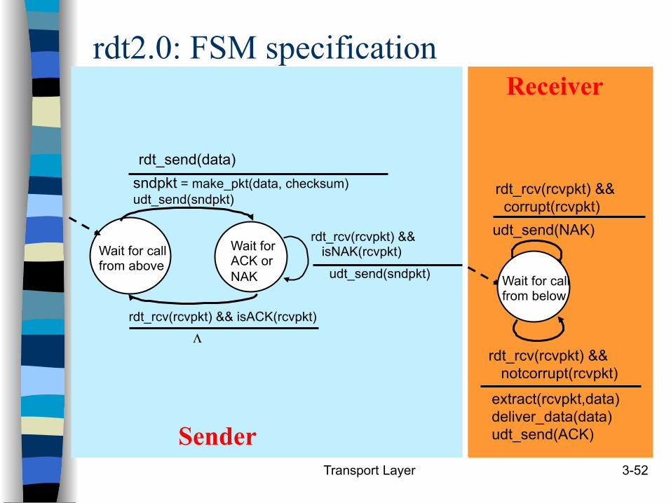
rdt2.0: FSM specification
Wait for call from above
sndpkt = make_pkt(data, checksum) udt_send(sndpkt)
extract(rcvpkt,data) deliver_data(data) udt_send(ACK)
rdt_rcv(rcvpkt) && notcorrupt(rcvpkt)
rdt_rcv(rcvpkt) && isACK(rcvpkt)
udt_send(sndpkt)
rdt_rcv(rcvpkt) && isNAK(rcvpkt)
udt_send(NAK)
rdt_rcv(rcvpkt) && corrupt(rcvpkt)
Wait for ACK or NAK Wait for call
from below
Sender
Receiver
rdt_send(data)
Λ

3-53
TCP: Overview ■ Full duplex data:
– bi-directional data flow in same connection
– MSS: maximum segment size
■ Connection-oriented: – handshaking (exchange
of control msgs) inits sender, receiver state before data exchange
■ Flow controlled: – sender will not overwhelm
receiver
■ Point-to-point: – one sender, one receiver
■ Reliable, in-order byte steam: – no “message boundaries”
■ Pipelined: – TCP congestion and flow
control set window size
■ Send & receive buffers
socketdoor
TCPsend buffer
TCPreceive buffer
socketdoor
segment
applicationwrites data
applicationreads data

Transport Layer 3-54
TCP segment structure
source port # dest port #
32 bits
application data (variable length)
sequence number acknowledgement number
Receive window
Urg data pnter checksum F S R P A U head
len not used
Options (variable length)
URG: urgent data (generally not used)
ACK: ACK # valid
PSH: push data now (generally not used)
RST, SYN, FIN: connection estab (setup, teardown
commands)
# bytes rcvr willing to accept
counting by bytes of data (not segments!)
Internet checksum
(as in UDP)

Transport Layer 3-55
TCP seq. #’s and ACKs Seq. #’s:
– byte stream “number” of first byte in segment’s data
ACKs: – seq # of next byte
expected from other side – cumulative ACK
Q: how receiver handles out-of-order segments
– A: TCP spec doesn’t say, - up to implementor
Host A Host B
Seq=42, ACK=79, data = ‘C’
Seq=79, ACK=43, data = ‘C’
Seq=43, ACK=80
User types ‘C’
host ACKs receipt of echoed ‘C’
host ACKs receipt of ‘C’, echoes back ‘C’
time
simple telnet scenario

Transport Layer 3-56
TCP: Retransmission Scenarios
Host A
Seq=100, 20 bytes data
time
premature timeout
Host B
Seq=92, 8 bytes data
Seq=92, 8 bytes data
Seq=
92 ti
meo
ut
Host A
Seq=92, 8 bytes data
ACK=100
loss
timeo
ut
lost ACK scenario
Host B
X
Seq=92, 8 bytes data
ACK=100
time Se
q=92
tim
eout
SendBase = 100
SendBase = 120
SendBase = 120
SendBase = 100

Transport Layer 3-57
TCP Retransmission Scenarios (more) Host A
Seq=92, 8 bytes data
ACK=100
loss
timeo
ut
Cumulative ACK scenario
Host B
X
Seq=100, 20 bytes data
ACK=120
time
SendBase = 120

TCP Congestion Control
(a) A fast network feeding a low capacity receiver. (b) A slow network feeding a high-capacity receiver.

Transport Layer 3-59
TCP Connection Management Recall: TCP sender, receiver
establish “connection” before exchanging data segments
■ initialize TCP variables:
– Initial seq. #s – Buffers, flow control info
(e.g. RcvWindow)
■ client: connection initiator Socket clientSocket = new
Socket("hostname","port number");
■ server: contacted by client Socket connectionSocket =
welcomeSocket.accept();
Three way handshake:
Step 1: client host sends TCP SYN segment to server – specifies initial seq # – no data
Step 2: server host receives SYN, replies with SYNACK segment – server allocates buffers – specifies server initial seq. #
Step 3: client receives SYNACK, replies with ACK segment, which may contain data

Transport Layer 3-60
TCP Connection Management (cont.)
Closing a connection:
client closes socket: clientSocket.close();
Step 1: client end system sends TCP FIN control segment to server
Step 2: server receives FIN, replies with ACK.
client
FIN
server
ACK
ACK
FIN
close
close
closed
timed
wai
t

Transport Layer 3-61
TCP Connection Management (cont.)
Step 3: client receives FIN, replies with ACK.
– Enters “timed wait” - will respond with ACK to received FINs
Step 4: server, receives ACK. Connection closed.
Step 5: after timeout, client ’s connection closed
client
FIN
server
ACK
ACK
FIN
closing
closing
closed
timed
wai
t closed

3-62
TCP Connection Management (cont)
TCP client lifecycle
TCP server lifecycle

TCP Finite State Machine
• TCP connection management Finite State Machine: 3-Way Handshake
• The heavy solid line is the normal path for a client.
• The heavy dashed line is the normal path for a server.
Step 1 of the 3-way handshake
Step 2 of the 3-way handshake
Step 3 of the 3-way handshake
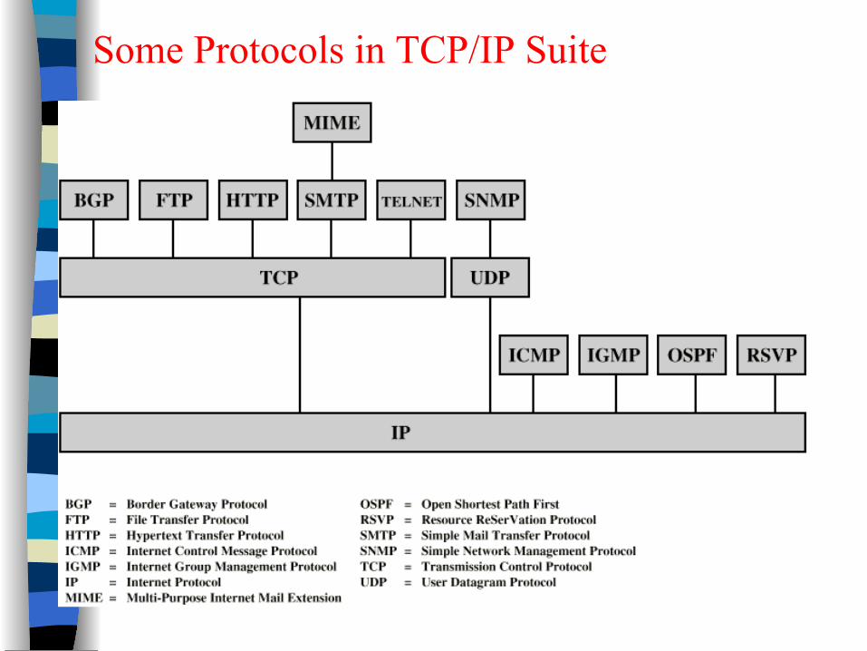
Some Protocols in TCP/IP Suite

Protocoles et Interconnexions
Course Overview and Introduction Dario Vieira Department of Computer Science EFREI