Embed Size (px)
Citation preview

Medium Access Control SublayerChapter 4
CN5E by Tanenbaum & Wetherall, © Pearson Education-Prentice Hall and D. Wetherall, 2011
• Channel Allocation Problem• Multiple Access Protocols• Ethernet• Wireless LANs• Broadband Wireless• Bluetooth• RFID• Data Link Layer Switching
Revised: August 2011
CN5E by Tanenbaum & Wetherall, © Pearson Education-Prentice Hall and D. Wetherall, 2011
The MAC Sublayer
Responsible for deciding who sends next on a multi-access link• An important part of the link
layer, especially for LANsPhysical
Link
Network
Transport
Application
MAC is in here!

Channel Allocation Problem (1)
For fixed channel and traffic from N users• Divide up bandwidth using FTM, TDM, CDMA, etc. • This is a static allocation, e.g., FM radio
This static allocation performs poorly for bursty traffic• Allocation to a user will sometimes go unused
CN5E by Tanenbaum & Wetherall, © Pearson Education-Prentice Hall and D. Wetherall, 2011

Channel Allocation Problem (2)
Dynamic allocation gives the channel to a user when they need it. Potentially N times as efficient for N users.
Schemes vary with assumptions:
Assumption Implication
Independent traffic
Often not a good model, but permits analysis
Single channel No external way to coordinate senders
Observable collisions
Needed for reliability; mechanisms vary
Continuous or slotted time
Slotting may improve performance
Carrier sense Can improve performance if available
CN5E by Tanenbaum & Wetherall, © Pearson Education-Prentice Hall and D. Wetherall, 2011
CN5E by Tanenbaum & Wetherall, © Pearson Education-Prentice Hall and D. Wetherall, 2011
Multiple Access Protocols
• ALOHA »• CSMA (Carrier Sense Multiple Access) »• Collision-free protocols »• Limited-contention protocols »• Wireless LAN protocols »

CN5E by Tanenbaum & Wetherall, © Pearson Education-Prentice Hall and D. Wetherall, 2011
ALOHA (1)
In pure ALOHA, users transmit frames whenever they have data; users retry after a random time for collisions• Efficient and low-delay under low load
`
CollisionCollision
Time
User
A
B
C
D
E

CN5E by Tanenbaum & Wetherall, © Pearson Education-Prentice Hall and D. Wetherall, 2011
ALOHA (2)
Collisions happen when other users transmit during a vulnerable period that is twice the frame time• Synchronizing senders to slots can reduce collisions
CN5E by Tanenbaum & Wetherall, © Pearson Education-Prentice Hall and D. Wetherall, 2011
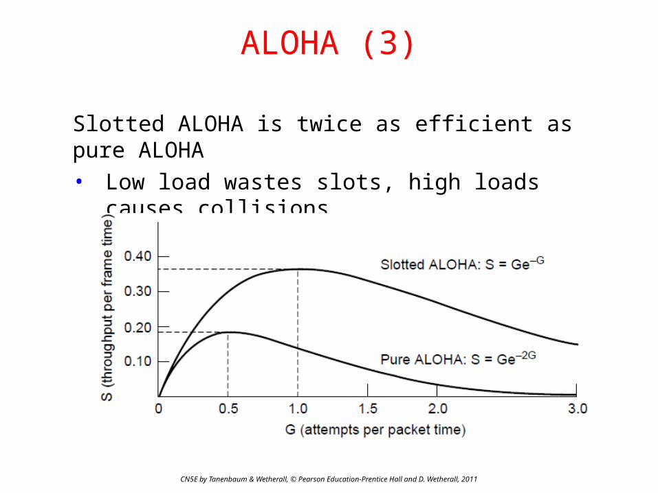
ALOHA (3)
Slotted ALOHA is twice as efficient as pure ALOHA• Low load wastes slots, high loads causes collisions • Efficiency up to 1/e (37%) for random traffic models

CSMA (1)
CN5E by Tanenbaum & Wetherall, © Pearson Education-Prentice Hall and D. Wetherall, 2011
CSMA improves on ALOHA by sensing the channel!• User doesn’t send if it senses someone else
Variations on what to do if the channel is busy:• 1-persistent (greedy) sends as soon as idle• Nonpersistent waits a random time then tries again• p-persistent sends with probability p when idle
CN5E by Tanenbaum & Wetherall, © Pearson Education-Prentice Hall and D. Wetherall, 2011
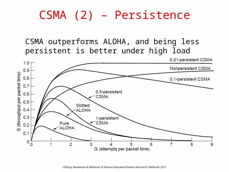
CSMA (2) – Persistence
CSMA outperforms ALOHA, and being less persistent is better under high load
CN5E by Tanenbaum & Wetherall, © Pearson Education-Prentice Hall and D. Wetherall, 2011
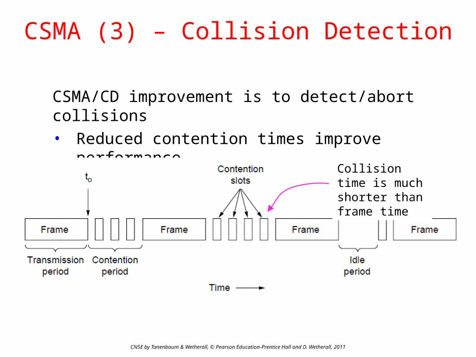
CSMA (3) – Collision Detection
CSMA/CD improvement is to detect/abort collisions• Reduced contention times improve performance
Collision time is much shorter than frame time

CN5E by Tanenbaum & Wetherall, © Pearson Education-Prentice Hall and D. Wetherall, 2011
Collision-Free (1) – Bitmap
Collision-free protocols avoid collisions entirely• Senders must know when it is their turn to send
The basic bit-map protocol:• Sender set a bit in contention slot if they have data• Senders send in turn; everyone knows who has data

CN5E by Tanenbaum & Wetherall, © Pearson Education-Prentice Hall and D. Wetherall, 2011
Collision-Free (2) – Token Ring
Token sent round ring defines the sending order• Station with token may send a frame before passing• Idea can be used without ring too, e.g., token bus
Station
Direction oftransmission
Token

CN5E by Tanenbaum & Wetherall, © Pearson Education-Prentice Hall and D. Wetherall, 2011
Collision-Free (3) – Countdown
Binary countdown improves on the bitmap protocol
• Stations send their address in contention slot (log N bits instead of N bits)
• Medium ORs bits; stations give up when they send a “0” but see a “1”
• Station that sees its full address is next to send

CN5E by Tanenbaum & Wetherall, © Pearson Education-Prentice Hall and D. Wetherall, 2011
Limited-Contention Protocols (1)
Idea is to divide stations into groups within which only a very small number are likely to want to send • Avoids wastage due to idle periods and collisions
Already too many contenders for a good chance of one winner

CN5E by Tanenbaum & Wetherall, © Pearson Education-Prentice Hall and D. Wetherall, 2011
Limited Contention (2) –Adaptive Tree Walk
Tree divides stations into groups (nodes) to poll• Depth first search under nodes with poll collisions• Start search at lower levels if >1 station expected
Level 0
Level 1
Level 2

CN5E by Tanenbaum & Wetherall, © Pearson Education-Prentice Hall and D. Wetherall, 2011
Wireless LAN Protocols (1)
Wireless has complications compared to wired.
Nodes may have different coverage regions• Leads to hidden and exposed terminals
Nodes can’t detect collisions, i.e., sense while sending• Makes collisions expensive and to be avoided
CN5E by Tanenbaum & Wetherall, © Pearson Education-Prentice Hall and D. Wetherall, 2011
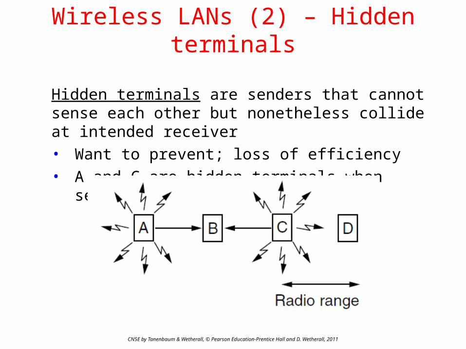
Wireless LANs (2) – Hidden terminals
Hidden terminals are senders that cannot sense each other but nonetheless collide at intended receiver• Want to prevent; loss of efficiency• A and C are hidden terminals when sending to B
CN5E by Tanenbaum & Wetherall, © Pearson Education-Prentice Hall and D. Wetherall, 2011
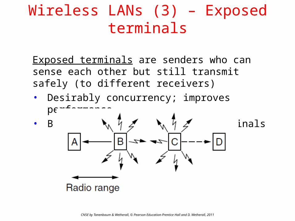
Wireless LANs (3) – Exposed terminals
Exposed terminals are senders who can sense each other but still transmit safely (to different receivers) • Desirably concurrency; improves performance• B A and C D are exposed terminals
CN5E by Tanenbaum & Wetherall, © Pearson Education-Prentice Hall and D. Wetherall, 2011
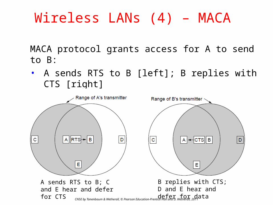
Wireless LANs (4) – MACA
MACA protocol grants access for A to send to B:• A sends RTS to B [left]; B replies with CTS [right] • A can send with exposed but no hidden terminals
A sends RTS to B; C and E hear and defer for CTS
B replies with CTS; D and E hear and defer for data

CN5E by Tanenbaum & Wetherall, © Pearson Education-Prentice Hall and D. Wetherall, 2011
Ethernet
• Classic Ethernet »• Switched/Fast Ethernet »• Gigabit/10 Gigabit Ethernet »

CN5E by Tanenbaum & Wetherall, © Pearson Education-Prentice Hall and D. Wetherall, 2011
Classic Ethernet (1) – Physical Layer
One shared coaxial cable to which all hosts attached• Up to 10 Mbps, with Manchester encoding• Hosts ran the classic Ethernet protocol for access
CN5E by Tanenbaum & Wetherall, © Pearson Education-Prentice Hall and D. Wetherall, 2011
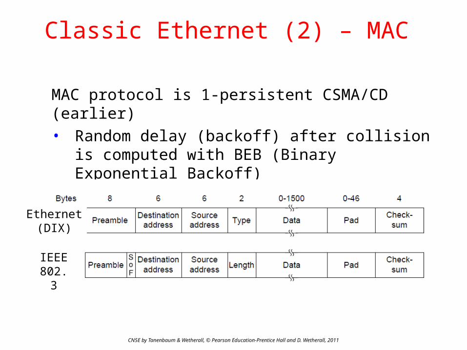
Classic Ethernet (2) – MAC
MAC protocol is 1-persistent CSMA/CD (earlier)• Random delay (backoff) after collision is computed
with BEB (Binary Exponential Backoff) • Frame format is still used with modern Ethernet.
Ethernet(DIX)
IEEE 802.3
CN5E by Tanenbaum & Wetherall, © Pearson Education-Prentice Hall and D. Wetherall, 2011
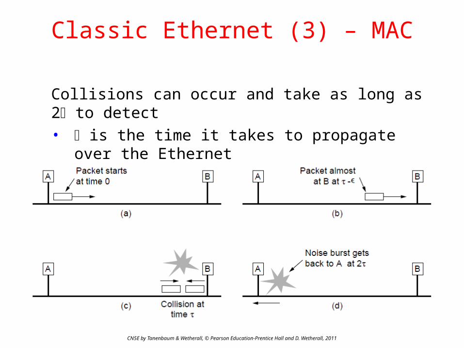
Classic Ethernet (3) – MAC
Collisions can occur and take as long as 2 to detect• is the time it takes to propagate over the Ethernet• Leads to minimum packet size for reliable detection

CN5E by Tanenbaum & Wetherall, © Pearson Education-Prentice Hall and D. Wetherall, 2011
Classic Ethernet (4) – Performance
Efficient for large frames, even with many senders• Degrades for small frames (and long LANs)
10 Mbps Ethernet,64 byte min. frame

CN5E by Tanenbaum & Wetherall, © Pearson Education-Prentice Hall and D. Wetherall, 2011
Switched/Fast Ethernet (1)
• Hubs wire all lines into a single CSMA/CD domain• Switches isolate each port to a separate domain
− Much greater throughput for multiple ports− No need for CSMA/CD with full-duplex lines

CN5E by Tanenbaum & Wetherall, © Pearson Education-Prentice Hall and D. Wetherall, 2011
Wireless LANs
• 802.11 architecture/protocol stack »• 802.11 physical layer »• 802.11 MAC »• 802.11 frames »

CN5E by Tanenbaum & Wetherall, © Pearson Education-Prentice Hall and D. Wetherall, 2011
802.11 Architecture/Protocol Stack (1)
Wireless clients associate to a wired AP (Access Point)• Called infrastructure mode; there is also ad-hoc
mode with no AP, but that is rare.
AccessPoint
Client
To Network

802.11 Architecture/Protocol Stack (2)
CN5E by Tanenbaum & Wetherall, © Pearson Education-Prentice Hall and D. Wetherall, 2011
MAC is used across different physical layers

802.11 physical layer
CN5E by Tanenbaum & Wetherall, © Pearson Education-Prentice Hall and D. Wetherall, 2011
• NICs are compatible with multiple physical layers− E.g., 802.11 a/b/g
Name Technique Max. Bit Rate
802.11b Spread spectrum, 2.4 GHz 11 Mbps
802.11g OFDM, 2.4 GHz 54 Mbps
802.11a OFDM, 5 GHz 54 Mbps
802.11n OFDM with MIMO, 2.4/5 GHz 600 Mbps
CN5E by Tanenbaum & Wetherall, © Pearson Education-Prentice Hall and D. Wetherall, 2011
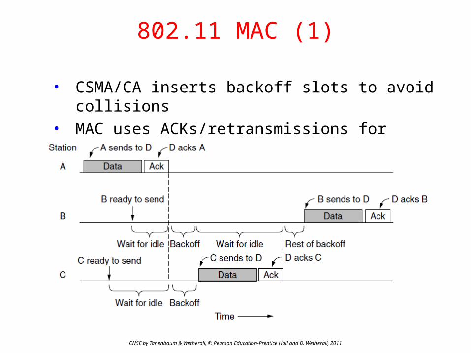
802.11 MAC (1)
• CSMA/CA inserts backoff slots to avoid collisions• MAC uses ACKs/retransmissions for wireless errors

CN5E by Tanenbaum & Wetherall, © Pearson Education-Prentice Hall and D. Wetherall, 2011
802.11 MAC (2)
Virtual channel sensing with the NAV and optional RTS/CTS (often not used) avoids hidden terminals
CN5E by Tanenbaum & Wetherall, © Pearson Education-Prentice Hall and D. Wetherall, 2011
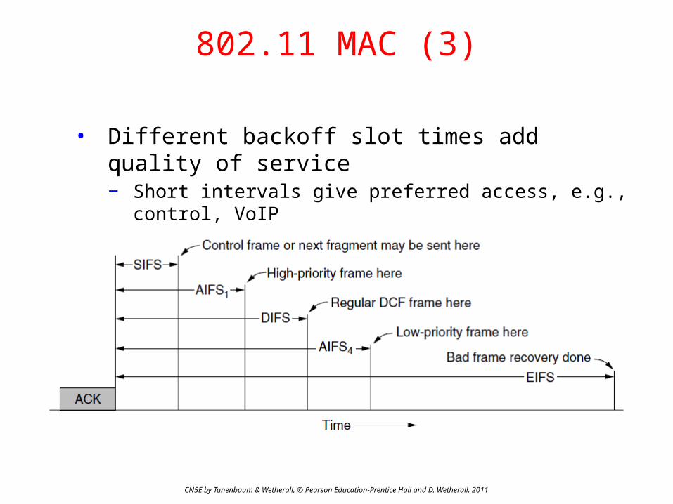
802.11 MAC (3)
• Different backoff slot times add quality of service− Short intervals give preferred access, e.g., control, VoIP
• MAC has other mechanisms too, e.g., power save
CN5E by Tanenbaum & Wetherall, © Pearson Education-Prentice Hall and D. Wetherall, 2011
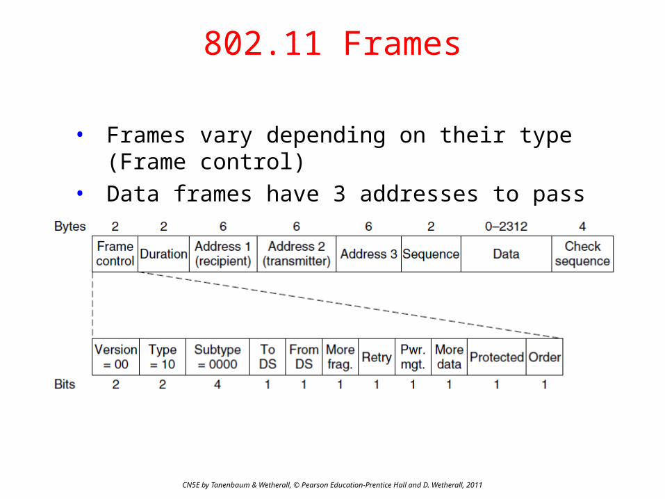
802.11 Frames
• Frames vary depending on their type (Frame control)• Data frames have 3 addresses to pass via APs
CN5E by Tanenbaum & Wetherall, © Pearson Education-Prentice Hall and D. Wetherall, 2011
Broadband Wireless
• 802.16 Architecture / Protocol Stack »• 802.16 Physical Layer »• 802.16 MAC »• 802.16 Frames »
CN5E by Tanenbaum & Wetherall, © Pearson Education-Prentice Hall and D. Wetherall, 2011
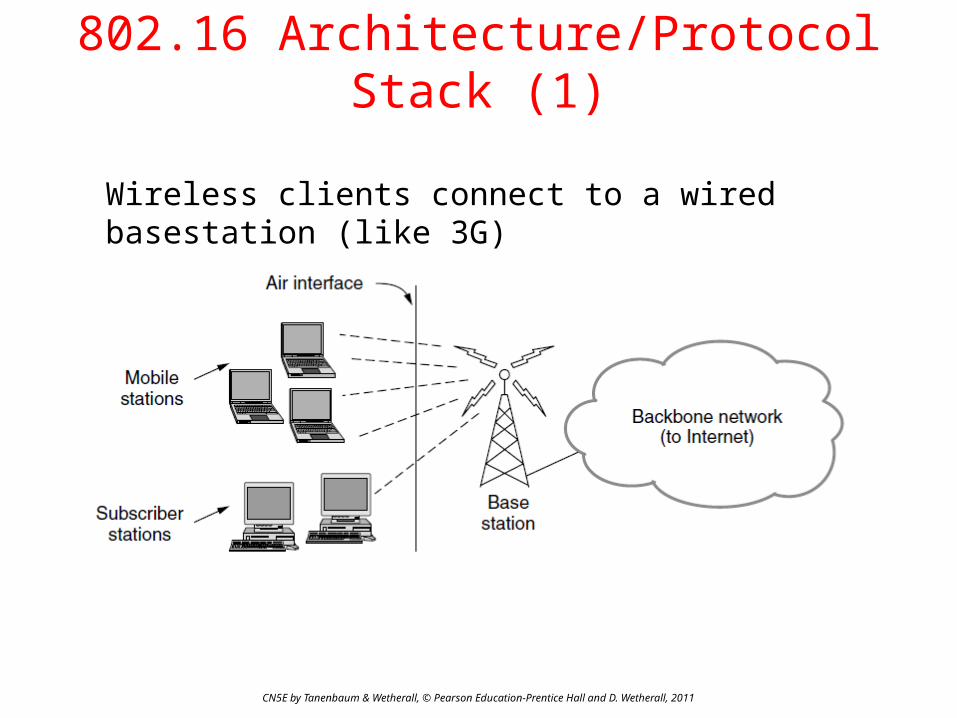
802.16 Architecture/Protocol Stack (1)
Wireless clients connect to a wired basestation (like 3G)
CN5E by Tanenbaum & Wetherall, © Pearson Education-Prentice Hall and D. Wetherall, 2011
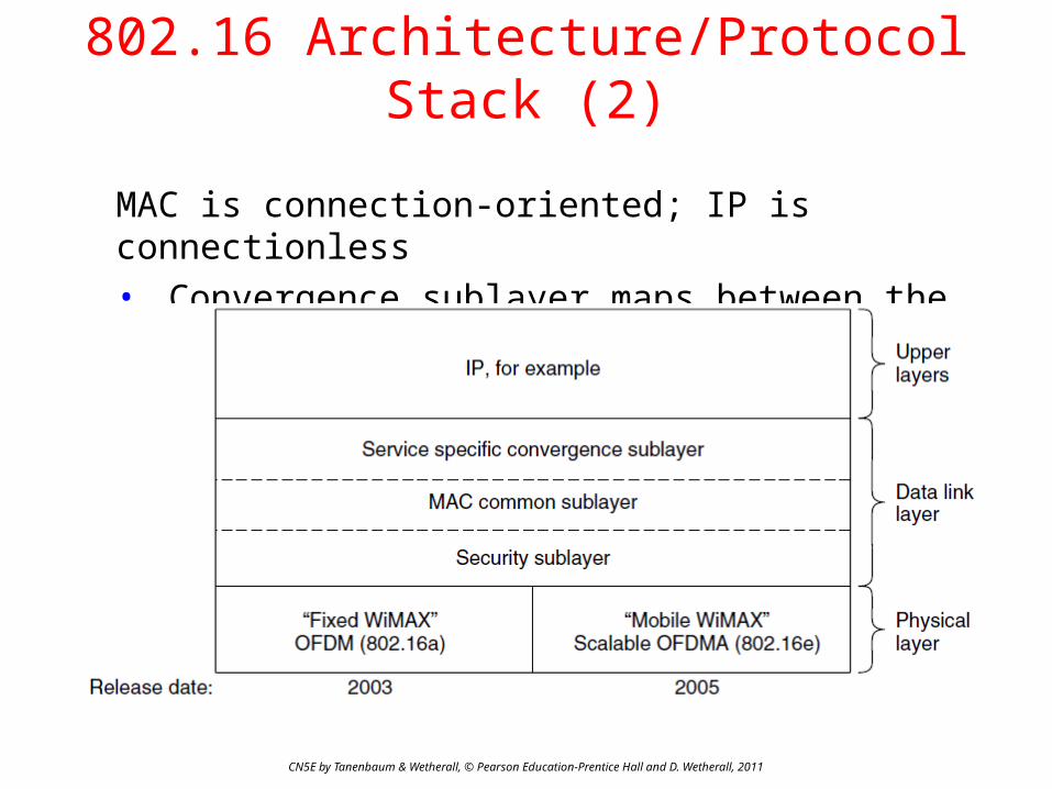
802.16 Architecture/Protocol Stack (2)
MAC is connection-oriented; IP is connectionless• Convergence sublayer maps between the two

CN5E by Tanenbaum & Wetherall, © Pearson Education-Prentice Hall and D. Wetherall, 2011
Bluetooth
• Bluetooth Architecture »• Bluetooth Applications / Protocol »• Bluetooth Radio / Link Layers »• Bluetooth Frames »

CN5E by Tanenbaum & Wetherall, © Pearson Education-Prentice Hall and D. Wetherall, 2011
Bluetooth Architecture
Piconet master is connected to slave wireless devices• Slaves may be asleep (parked) to save power • Two piconets can be bridged into a scatternet

CN5E by Tanenbaum & Wetherall, © Pearson Education-Prentice Hall and D. Wetherall, 2011
Bluetooth Applications / Protocol Stack
Profiles give the set of protocols for a given application• 25 profiles, including headset, intercom, streaming
audio, remote control, personal area network, …
Bluetooth Radio / Link Layers
CN5E by Tanenbaum & Wetherall, © Pearson Education-Prentice Hall and D. Wetherall, 2011
Radio layer• Uses adaptive frequency hopping in 2.4 GHz band
Link layer• TDM with timeslots for master and slaves• Synchronous CO for periodic slots in each direction• Asynchronous CL for packet-switched data• Links undergo pairing (user confirms passkey/PIN)
to authorize them before use

CN5E by Tanenbaum & Wetherall, © Pearson Education-Prentice Hall and D. Wetherall, 2011
Data Link Layer Switching
• Uses of Bridges »• Learning Bridges »• Spanning Tree »• Repeaters, hubs, bridges, .., routers, gateways »• Virtual LANs »
CN5E by Tanenbaum & Wetherall, © Pearson Education-Prentice Hall and D. Wetherall, 2011
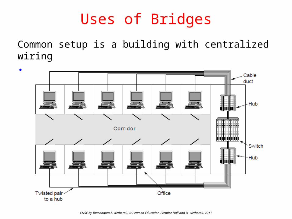
Uses of Bridges
Common setup is a building with centralized wiring• Bridges (switches) are placed in or near wiring closets
CN5E by Tanenbaum & Wetherall, © Pearson Education-Prentice Hall and D. Wetherall, 2011
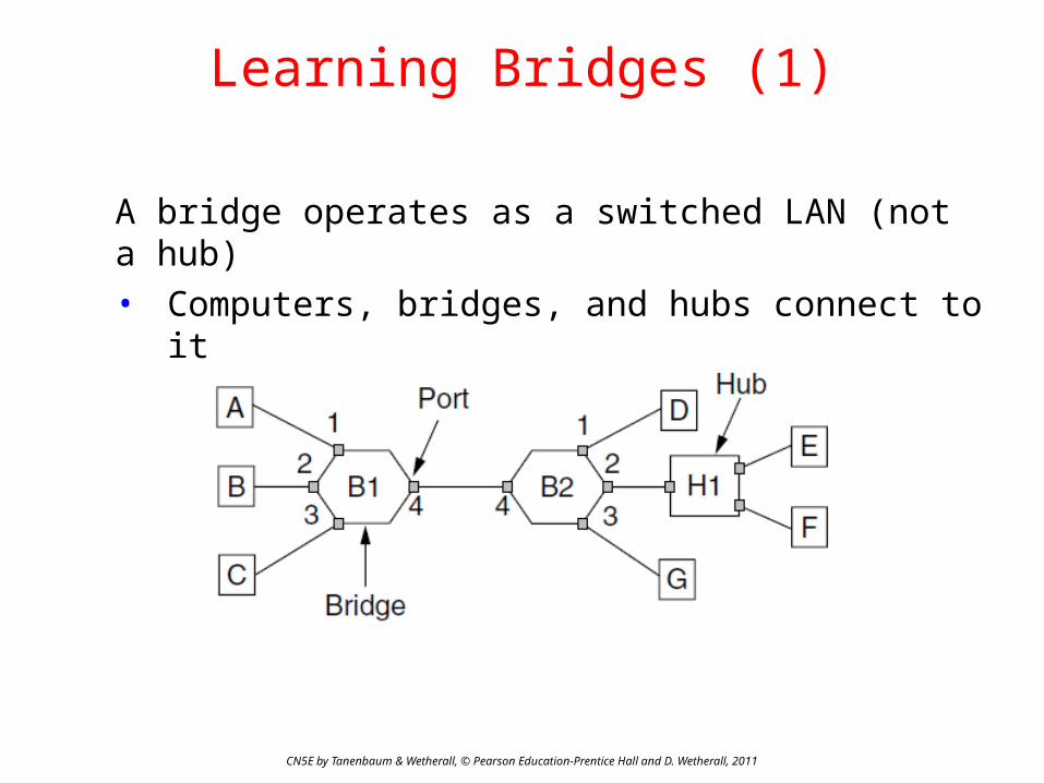
Learning Bridges (1)
A bridge operates as a switched LAN (not a hub)• Computers, bridges, and hubs connect to its ports

CN5E by Tanenbaum & Wetherall, © Pearson Education-Prentice Hall and D. Wetherall, 2011
Learning Bridges (2)
Backward learning algorithm picks the output port:• Associates source address on frame with input port• Frame with destination address sent to learned port• Unlearned destinations are sent to all other ports
Needs no configuration• Forget unused addresses to allow changes• Bandwidth efficient for two-way traffic

CN5E by Tanenbaum & Wetherall, © Pearson Education-Prentice Hall and D. Wetherall, 2011
Learning Bridges (3)
Bridges extend the Link layer:• Use but don’t remove Ethernet header/addresses• Do not inspect Network header

CN5E by Tanenbaum & Wetherall, © Pearson Education-Prentice Hall and D. Wetherall, 2011
Spanning Tree (1) – Problem
Bridge topologies with loops and only backward learning will cause frames to circulate for ever• Need spanning tree support to solve problem
CN5E by Tanenbaum & Wetherall, © Pearson Education-Prentice Hall and D. Wetherall, 2011
Spanning Tree (2) – Algorithm
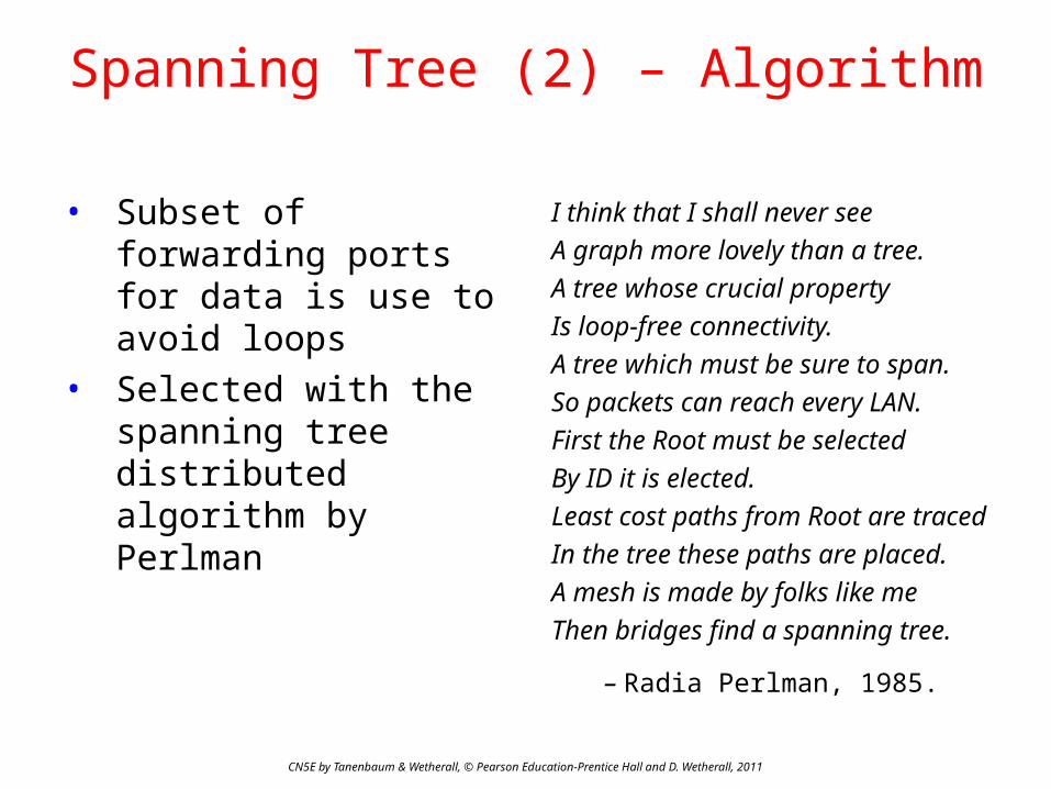
• Subset of forwarding ports for data is use to avoid loops
• Selected with the spanning tree distributed algorithm by Perlman
I think that I shall never see
A graph more lovely than a tree.
A tree whose crucial property
Is loop-free connectivity.
A tree which must be sure to span.
So packets can reach every LAN.
First the Root must be selected
By ID it is elected.
Least cost paths from Root are traced
In the tree these paths are placed.
A mesh is made by folks like me
Then bridges find a spanning tree.
– Radia Perlman, 1985.
CN5E by Tanenbaum & Wetherall, © Pearson Education-Prentice Hall and D. Wetherall, 2011
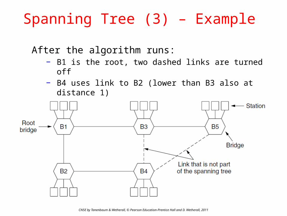
Spanning Tree (3) – Example
After the algorithm runs:− B1 is the root, two dashed links are turned off− B4 uses link to B2 (lower than B3 also at distance 1)− B5 uses B3 (distance 1 versus B4 at distance 2)

CN5E by Tanenbaum & Wetherall, © Pearson Education-Prentice Hall and D. Wetherall, 2011
Repeaters, Hubs, Bridges, Switches, Routers, & Gateways
Devices are named according to the layer they process• A bridge or LAN switch operates in the Link layer

CN5E by Tanenbaum & Wetherall, © Pearson Education-Prentice Hall and D. Wetherall, 2011
Virtual LANs (1)
VLANs (Virtual LANs) splits one physical LAN into multiple logical LANs to ease management tasks• Ports are “colored” according to their VLAN
CN5E by Tanenbaum & Wetherall, © Pearson Education-Prentice Hall and D. Wetherall, 2011
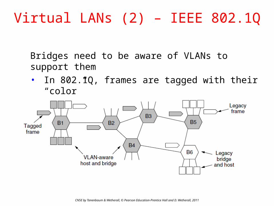
Virtual LANs (2) – IEEE 802.1Q
Bridges need to be aware of VLANs to support them• In 802.1Q, frames are tagged with their “color”• Legacy switches with no tags are supported
CN5E by Tanenbaum & Wetherall, © Pearson Education-Prentice Hall and D. Wetherall, 2011
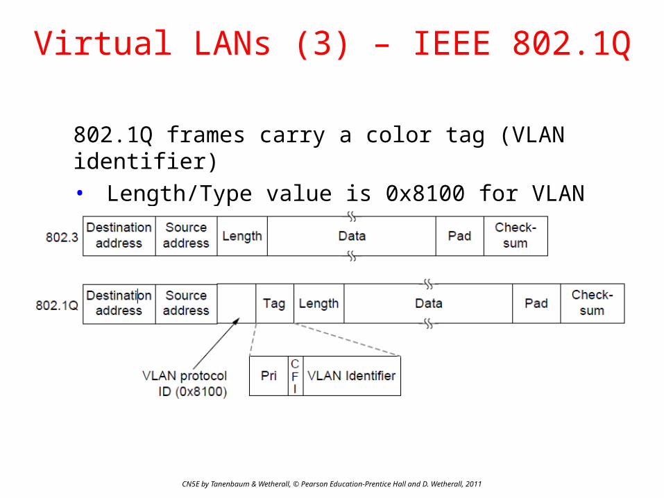
Virtual LANs (3) – IEEE 802.1Q
802.1Q frames carry a color tag (VLAN identifier)• Length/Type value is 0x8100 for VLAN protocol

End
Chapter 4
CN5E by Tanenbaum & Wetherall, © Pearson Education-Prentice Hall and D. Wetherall, 2011