Embed Size (px)
Citation preview
28/02/2017 1
CMPE 344 Computer NetworksSpring 2017
Foundations
Reading: Peterson and Davie, §1.1-1.5
Sources of slides:Computer networks: A systems Approach by Peterson and Davie, © Morgan Kaufmann, 2010CN5E by Tanenbaum & Wetherall, © Pearson Education-Prentice Hall and D. Wetherall, 2011Computer Networking by Jim Kurose, Keith Ross, © Pearson/Addison Wesley, 2016

2
Goals of CMPE 344• Emphasize on design choices made when
building computer networks• Understand why networks are designed the way
they are• Discuss “systems” approach to understand the
big picture• Gain insight on architectural implications and
interaction of components rather than focusing on rigidly defined layers

Network Applications• Most people are familiar with network through
applications:– World Wide Web– Email– Online social network– Streaming audio/video– Videoconferencing (e.g. SkypeTM)– File sharing– Instant messaging– … and many more
3

4
Links and nodes• A link is a physical medium that connects
computers or nodes.– A node is a piece of hardware such as a PC,
a switch, a router, etc….• Key challenge in network design: Scalability
– A system that is designed to support growth to an arbitrarily large size is said to scale
– How should we connect all the nodes in the world?
5
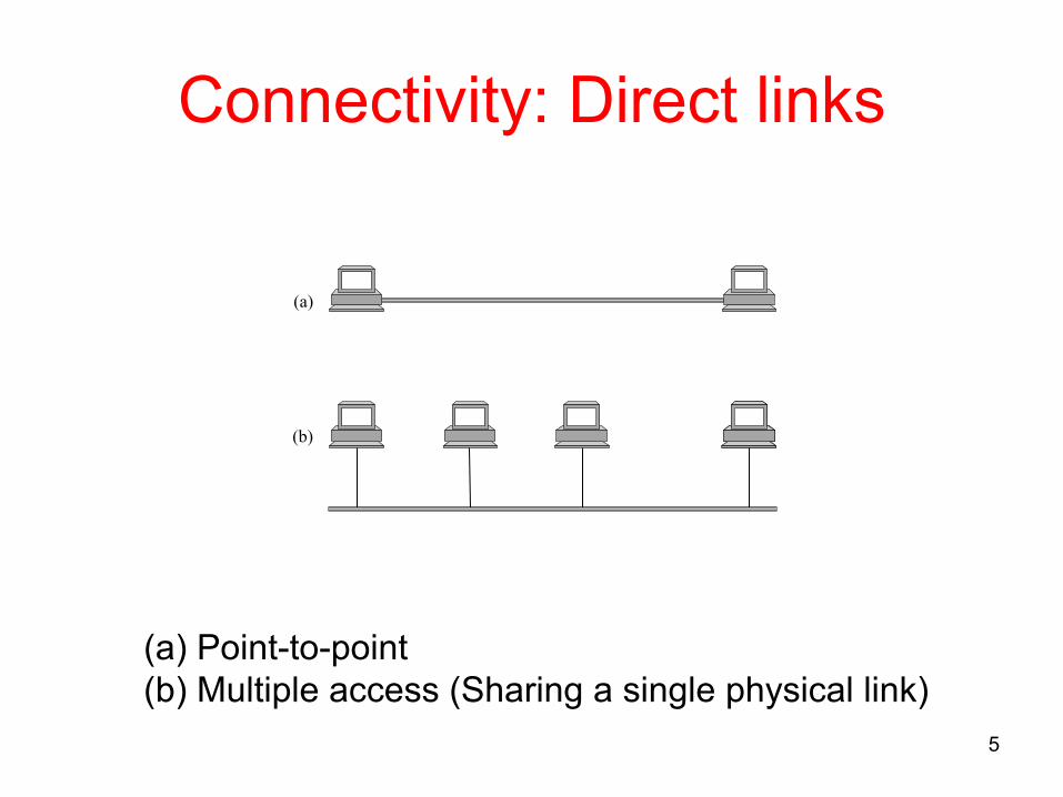
Connectivity: Direct links
(a)
(b)
(a) Point-to-point(b) Multiple access (Sharing a single physical link)

6
Connectivity: Switched network
• Connectivity between two nodes does not necessarily imply a direct physical connection between them
• Nodes can be indirectly connected: A switched network contains forwarding nodes or switches

7
Types of switched networks• Circuit-switched networks
– Telephone networks– A dedicated circuit across a sequence of links
is established. Source node sends a stream of bits across this circuit to a destination node
• Packet-switched networks – Computer networks– Discrete blocks of data are sent in a (usually)
store-and-forward manner

8
Packets• Nodes in packet switched networks send
discrete blocks of data to each other– These blocks correspond to some piece of
application data such as a file, a piece of email or an image
– The blocks are called packets or messages(more on this later)

9
Store-and-forward• In packet switched networks, each node
– first receives complete packet over some link – stores the packet in its internal memory– and then forwards the complete packet to the
next node• Primary function of packet switches is to store
and forward packets

10
Interconnection of networks
• A node that connects two or more networks is called a router or gateway
• The Internet is an example of an internet
An internetwork or an internet

11
Addressing and routing• Each node in a network must have an identifier called its
address (a byte string)• When a source node wants the network to deliver a
message to a certain destination, it must specify the address of the destination node
• If the sending and receiving nodes are not directly connected, switches and routers use the address to decide how to forward the message toward the destination
• The process of determining systematically how to forward messages toward the destination node based on its address is called routing

12
Broadcasting and multicasting• Unicast: Source sends a message to a single
destination node• Broadcast: Source sends a message to all the
nodes on the network• Multicast: Source sends a message to some
subset of the other nodes (but not all of them)• Thus, in addition to node-specific addresses, a
network may have to support broadcast and multicast addresses as well

13
Cost-effective resource sharing• How do hosts share the network and the same
link when they all want to use it at the same time?
• Multiplexing: Sharing a system resource among multiple users
L2
L3
R2
R3
L1 R1
Switch 1 Switch 2
Multiplexing/demultiplexing
14
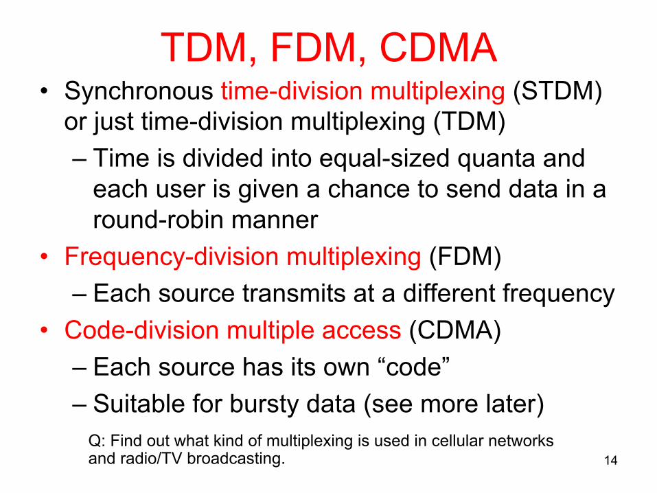
TDM, FDM, CDMA • Synchronous time-division multiplexing (STDM)
or just time-division multiplexing (TDM)– Time is divided into equal-sized quanta and
each user is given a chance to send data in a round-robin manner
• Frequency-division multiplexing (FDM)– Each source transmits at a different frequency
• Code-division multiple access (CDMA)– Each source has its own “code”– Suitable for bursty data (see more later)
Q: Find out what kind of multiplexing is used in cellular networks and radio/TV broadcasting.
15
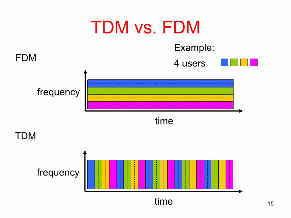
TDM vs. FDMFDM
frequency
timeTDM
frequency
time
4 usersExample:

16
Limitations of TDM and FDM
• If one of the pairs does not have any data to send, its share of physical link (time quantum or frequency) remains idle even if one of the other pairs has data to transmit
• In computer communications the idle time can be large! (Q: Why?)
• Also, the maximum number of flows in these schemes is fixed ahead of time

17
Statistical Multiplexing• Not all of the pairs are active at the same time!• Like STDM: Link is shared over time• Unlike STDM: Data is transmitted from each
user on demand rather than in a predetermined slot
• Statistical multiplexing is efficient!
Q: How does one ensure that transmission decisions are made fairly?

18
More on statistical multiplexing• A packet switched network fragments a large
message into packets (that have a maximum size) so that other flows can have a turn to transmit their own
• Receiver will have to reassemble the packets back into original message
■ ■ ■
Multiplexing packetsonto a shared link

19
More on statistical multiplexing• The switch may have to buffer packets in its
memory if it receives packets faster than the shared link can handle
• If switch receives packets faster than it can send them for an extended period of time, resource will be congested– Packets will be dropped– Packets will be delayed excessively

Statistical multiplexing vs. circuit switching
• Suppose users share a 1 Mbps link and each user alternates between periods of activity (generates data at constant rate 100 kbps) and periods of inactivity
• Further, each user is active 10% of time• With circuit switching (TDM, FDM), 100 kbps must be
reserved for each user at all times– E.g., TDM: 1-sec. frame is divided into 10 time slots of
100 ms each– The link can support only 10 simultaneous users
20

Statistical multiplexing vs. circuit switching
• With statistical multiplexing, the probability that each user is active is 0.1 (10%)
• If there are 35 users, the probability that there are 11 or more simultaneously active users is approx. 0.0004 (see next slide)
• When there are 10 or fewer simultaneously active users (which happens with probability 0.9996), the aggregate arrival rate of data is less than or equal to 1 Mbps (the output rate of the link)
• When there are more than 10 active users, queue will begin to grow (until aggregate rate falls below 1 Mbps)
• The probability of having more than 10 simultaneously active users is miniscule, the performance is the same as circuit switching, and 3 times the number of users are allowed
21

Statistical multiplexing vs. circuit switching
• Let p=0.1• Probability of having n simultaneously active
users out of 35 at any given time is
– 35𝑛 pn(1-p)35-n
• Probability that there are 11 or more users transmitting simultaneously is
– 1 − ∑ 35𝑛 𝑝* 1 − 𝑝 +,-*./
*0/ = 0.0004
22

Support for common services• Logical channels
– Application-to-application communication path or a pipe
23
Processes communicating over an abstract channel
Channel must meet the functionality requirements of applications

24
Characterization of networks according to their sizes
PAN Personal area network Around an individual
SAN Storage area network In a room
LAN Local area network ~ 1 km
MAN Metropolitan area network ~ 10 km
WAN Wide area network Worldwide

25
Challenges to reliability• Bit errors
– 1 is turned into a 0 or vice versa– Causes: Lightning, power surges, microwave ovens– These are rare: 1 out of 106-107 on copper cable,
1 out of 1012-1014 on fiber• Packet losses
– Uncorrectable bit errors or packet drops at intermediate nodes due to lack of buffer space
• Node- or link-level failures– Crashed computers, broken links, misconfiguration

26
Other challenges• Messages are delayed• Messages are delivered out-of-order• Third parties eavesdrop
A major requirement of a network is to recover from certain kinds of failures

27
Layering• A fundamental design and implementation
concept• When designing and analyzing complex
systems, we usually abstract away the details of components and provide an interface for other components of the system
• Services provided at higher layers are implemented in terms of services provided by lower layers

28
Protocols• Protocols
– are abstract objects that make up the layers of a network system
– provide communication service that higher level objects (e.g. application processes or higher level protocols) use to exchange messages
– In fact, the term “protocol” is “overloaded”: Specification of interface or module that implements it
• Two different interfaces are generally provided– Service interface: To other objects on the same
computer– Peer interface: To a protocol’s counterpart (peer) on
another machine

29
Service and peer interfaces of protocols

30
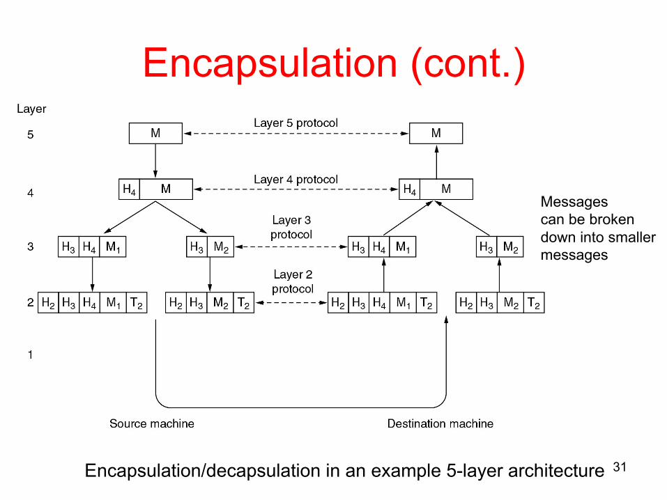
Encapsulation• A header (and/or trailer) is attached to a
message body or payload• Referred to as multiplexing and demultiplexing
up and down the protocol graph• Headers attached to messages contain an
identifier that records the higher level object to which the message belongs
• Trailers may contain information for error detection/correction
31
Encapsulation (cont.)
Encapsulation/decapsulation in an example 5-layer architecture
Messagescan be broken down into smaller messages

32
Network architecture• The set of rules governing the form and context
of a protocol graph is called a network architecture– The suite of protocols that make up a network
system is represented by a protocol graph• International Standards Organization (ISO) and
Internet Engineering Task Force (IETF) are examples of standardization bodies for network architectures

33
Open Systems Interconnection (OSI) reference model
One or more nodeswithin the network
End host
Application
Presentation
Session
Transport
Network
Data link
Physical
Network
Data link
Physical
Network
Data link
Physical
End host
Application
Presentation
Session
Transport
Network
Data link
Physical

Description of layers• Physical Layer
– Handles the transmission of raw bits over a communication link• Data Link Layer
– Collects a stream of bits into a larger aggregate called a frame– Network adaptor along with device driver in OS implement the
protocol in this layer• Network Layer
– Handles routing among nodes within a packet-switched network– Unit of data exchanged between nodes in this layer is called a
packet
The lower three layers are implemented on all network nodes
34

Description of layers• Transport Layer
– Implements a process-to-process channel– Unit of data exchanges in this layer is called a message
• Session Layer– Provides a name space that is used to tie together the potentially
different transport streams that are part of a single application• Presentation Layer
– Concerned about the format of data exchanged between peers• Application Layer
– Standardize common type of exchanges
The transport layer and the higher layers typically run only on end-hosts and not on the intermediate switches and routers
35

36
Internet Architecture
■ ■ ■
FTP
TCP UDP
IP
NET 1 NET 2 NET n
HTTP NV TFTP
• Evolved out of ARPANET (DARPA/US DoD)• Significance of the hourglass: Minimal and carefully chosen
set of global capabilities that allow many higher layer applications and lower layer communication technologies to coexist, share capabilities, and evolve rapidly
TCP UDPIPNetwork
Application
Protocol graph: The hourglass shape
Reference model:No strict layering
IETF Internet architecture• Main features
– Does not imply strict layering. The application is free to bypass the defined transport layers and to directly use IP or other underlying networks
– An hour-glass shape – wide at the top, narrow in the middle and wide at the bottom. IP serves as the focal point for the architecture
– In order for a new protocol to be officially included in the architecture, there needs to be both a protocol specification and at least one (and preferably two) representative implementations of the specification
37

38
Implementing network software• Network protocols are implemented as part of the
operating system (OS)• OS provides application programming interface (API) to
network services• Socket interface
– Socket: Point where a local application process attaches to the network
– Socket operations: Creating a socket, attaching the socket to the network, sending/receiving messages, closing the socket

39
Network performance• Network performance is measured in two fundamental
ways– Bandwidth (or sometimes throughput): Number of bits
that can be transmitted over the network in a certain period of time (e.g., 10 Mbps: i.e. it takes 0.1 µs to transmit each bit)
• Notation: KB = 210 bytes; Mbps = 106 bits per second– Latency (or delay): Time it takes a message to travel
from one end of a network to the other (e.g., 24 ms in transcontinental networks)
• Round-trip time (RTT): Time it takes to send a message from one end of a network to the other and back

40
Bandwidth
1
(a)
1
(b)
(a) Bits transmitted at 1 Mbps(b) Bits transmitted at 2 Mbps
We can talk about the bandwidth of a single physical link orthe bandwidth of a logical process-to-process channel

41
Bandwidth vs. throughput• In networking, it is customary to refer to bits-per-second
(bps) as the bandwidth• Depending on the context (communication theory, signal
processing), bandwidth also refers to the range of signals that can be accommodated– e.g., Voice-grade telephone line, 300-3300 Hz, has a
bandwidth of 3000 Hz– Relationship between bps and Hz will be established
in Chapter 2, Shannon’s Theorem• Throughput is the bits-per-second (bytes-per-second,
packets-per-second, etc.) that we can actually transmit in practice (refers to measured performance)

42
Delay and throughput• In general, latency has 3 main components
– Latency = Propagation + Transmit + Queue– Propagation = Distance / SpeedOfLight– Transmit = Size (bits) / Bandwidth (bps)
• Be careful since delay/latency/RTT are context dependent– We will make it explicit whenever necessary
• Effective end-to-end throughput– Throughput = TransferSize (bits) / TransferTime (sec)

Bandwidth vs. Latency• Relative importance of bandwidth and latency
depends on application– For large file transfer, bandwidth is critical– For small messages (HTTP, NFS, etc.), latency is
critical– Variance in latency (jitter) can also affect some
applications (e.g., audio/video conferencing) (see more later)
43

44
Latency vs. bandwidth domination10,000
5000
2000
1000
500
200
100
50
20
10
5
2
110010
RTT (ms)
1-MB object, 1.5-Mbps link1-MB object, 10-Mbps link2-KB object, 1.5-Mbps link2-KB object, 10-Mbps link1-byte object, 1.5-Mbps link1-byte object, 10-Mbps link

45
Delay x Bandwidth product• Volume of the pipe: The maximum number of
bits that could be in transit through the pipe at any given interval
• A transcontinental channel with a one-way latency of 50 ms and a bandwidth of 45 Mbps is able to hold 50x10-3 sec x 45x106 bits/sec = 2.25x106 bits = 280 KB of data
Bandwidth
Delay

46
Sample delay x bandwidth productsLink type Bandwidth Distance RTT Delay x BW
Dial-up 56 Kbps 10 km 87 µs 5 bits
Wireless LAN
54 Mbps 50 m 0.33 µs 18 bits
Satellite 45 Mbps 35,000 km 230 ms 10 Mb
Cross-country fiber
10 Gbps 4,000 km 40 ms 400 Mb
Here, RTT = 2 * Propagation&processing delay

47
Keeping the pipe full• Delay x bandwidth is important to know when
constructing high-performance networks because it corresponds to how many bits the sender must transmit before the first bit arrives at the receiver
• If the sender is expecting the receiver to somehow signal that bits are starting to arrive the sender can send up to 2 delay x bandwidth (= RTT x bandwidth) worth of data before hearing from the receiver

Delay x bandwidth
48
Both links have an RTT of 100 ms A 1-MB file would take 80 RTTs on 1-Mbps link but only fill the 1-Gbps link 1/12 of one time

49
Time scales and performance• Average vs. “instantaneous” bandwidth:
– Time interval over which average is computed is important
– Suppose a video application needs 2 Mbps on average:
• If it transmits 1 Mb in first second and 3 Mb in the following second, over the 2-second interval average rate is 2 Mbps
• However, just knowing the average may not be enough. What if the network can support no more than 2 Mb in any one second
• Generally, one puts an upper bound on how large a “burst” can be (Burst: Peak rate maintained for some period of time)
50
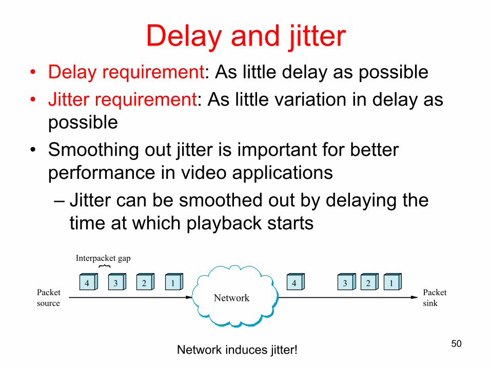
Delay and jitter• Delay requirement: As little delay as possible• Jitter requirement: As little variation in delay as
possible• Smoothing out jitter is important for better
performance in video applications– Jitter can be smoothed out by delaying the
time at which playback starts
Network induces jitter!
Network
Interpacket gap
Packetsource
Packetsink
1234 1234