Embed Size (px)
Citation preview

Operating Manual

2
Congratulations on your purchase of the ProMark® Apex Locator with touch screen.
Please do not hesitate to contact DENTSPLY Tulsa Dental Specialties for help or if you have any questions. Keep this manual for further reference.DENTSPLY Tulsa Dental Specialties reserves the right to change the information and data contained in these Directions For Use at anytime and without prior notice.These Directions For Use are available in French upon request.
DENTSPLY Tulsa Dental SpecialtiesDENTSPLY International, Inc.608 Rolling Hills Drive Johnson City, TN 37604 1-800-662-1202 1-800-597-2779 (fax) www.DENTSPLY.comwww.DENTSPLY.com/endo-patents

3
Contents1 Identification of Symbols ....................4
1.1 Symbols used in these Directions for Use .................................4
1.2 Symbols used on Packaging, Device and Parts ..................................4
2 Indications for Use ..............................5
3 Contraindications ................................5
4 Warnings .............................................5
5 General Precautions ............................6
6 Adverse Reactions .............................6
7 Step-by-Step Instructions ..................6
7.1 Standard Components ..........................6
7.2 Installation ............................................7
7.2.1 Charger ................................................7
7.2.2 Rechargeable Battery ...........................7
7.3 Description of User Interface ................8
7.4 Operation .............................................9
7.4.1 Connecting the Device ..........................9
7.4.2 Starting Length Determination ........... 10
7.4.3 Apex Localization ............................... 11
7.4.4 Sound Level Selection ........................ 12
7.4.5 Automatic Shutdown .......................... 13
7.5 Length Determination ......................... 13
7.5.1 Troubleshooting .................................. 14
7.5.2 Comparison of Electronic Length Determination Versus Radiography ..... 15
7.6 Device Setup ...................................... 15
7.6.1 Settings Menu Features ..................... 16
7.6.2 DR’S CHOICE Working Length Line ..... 16
7.6.3 CHECK Mode ...................................... 18
7.6.4 DEMO Mode .......................................20
8 Maintenance, Cleaning and Sterilization .......................................21
8.1 General ...............................................21
8.2 Disinfection and Sterilization Procedure ...........................................22
9 Manufacturer ....................................23
10 Warranty ............................................23
11 Disclaimer .........................................23
12 Technical Data ...................................24
Annex
Electromagnetic Compatibility .......................25

4
1 Identification of Symbols
1.1 Symbols used in these Directions for Use
If the instructions are not being fol-lowed properly, operation may result in hazards for the product or the user/patient.
Additional information, explanation on operation and performance.WARNING NOTE
1.2 Symbols used on Packaging, Device and Parts
Serial number Consult Instructions For Use
Class II productSpecial disposal of waste electrical and electronic equipment(Directive 2002/96/EEC)
Shock Type BF Fragile
Keep dry! Content (quantity)
X-ray Direct current
Temperature limitation Atmospheric pressure limitation
Humidity limitation

5
2 Indications for UseFOR DENTAL USE ONLY!
ProMark® is a microprocessor controlled device used for locating apex.
3 Contraindications Use of the ProMark® is contraindicated on patients or by operators having implanted electronic devices such as pacemaker, etc.
4 Warnings In this chapter a description of serious adverse reactions and potential safety hazards for the product or the user/patient is included. Please read the following warnings before use.
WARNINGS• The device may be used only by licensed dentists acting in accordance with federal, state or provincial regulations.• Do not expose the device to direct or indirect sources of heat. Store and use the device in a safe environment.• Do not use the device in the presence of flammable anaesthetic mixtures.• Do not immerse in liquid.• Use only original accessories and battery.• Do not use the device if it appears to be damaged or defective.• Do not perform repairs or modifications to the device without prior authorization by DENTSPLY Tulsa Dental Specialties. • Do not connect the device to or use it in combination with any other apparatus or system. • Device only works while running on battery power.
• Do not use the device as an integral component of any other apparatus or inappropriate system. DENTSPLY Tulsa Dental Specialties will not be responsible for accidents, equipment damage, bodily injury or any other trouble which results from ignoring this prohibition.
NOTEThe device complies with the Electromagnetic compatibility standard (IEC 60601-1-2).

6
5 General PrecautionsRead these safety precautions thoroughly prior to use. These precautions allow you to use the product safely, preventing harm to you and to others.It is of the utmost importance that this manual is preserved for future reference.It is recommended to take an X-ray prior to the use of the device and to compare the results obtained by both methods.The manufacturer declines any responsibility in the case of: • Use of the device for applications other than those specified in the directions for use.• Modifications or repairs performed by persons not authorized by the manufacturer.• Use of non-original components or components other than those specified in the STANDARD COMPONENTS chapter (7.1).
6 Adverse Reactions There are no known adverse reactions.
7 Step-by-Step InstructionsRefer to the WARNINGS chapter (4) to verify any special care to exercise before starting to use the device. When opening the package and prior to installation, check the device for completeness. Report any damage sustained during shipping or any missing parts to DENTSPLY Tulsa Dental Specialties within 24 hours of opening of the device.
Ambient Conditions for Operation • Ambient temperature: +10 °C to + 40 °C (50 °F to 104 °F).• Relative humidity: 10% to 90%.• Atmospheric pressure: 70 kPa to 106 kPa.
WARNINGDo not store the device in damp places or in places where it will come into extended contact with liquids of any kind.
Fig. 1 Incorrect placement of device.
7.1 Standard Components
• 1 ProMark® Apex Locator.• 1 Charger.• 1 Tester for operation check. • 1 Accessory set including: 1 measuring cable, 2 lip clips, 2 file clips, 1 touch probe. • Directions For Use.
NOTENone of the accessories is delivered disinfected or sterilized!

7
7.2 Installation
7.2.1 Charger
Attach the charger plug adapter (Fig. 2). Slide the plug adapter downwards into the slots until it locks in place with a click.
USA /Canada plug adapter
Fig. 2 Plug adapter and charger
WARNINGS• Prior to first use, the battery must be charged for 6 hours! • Use the original charger only.
7.2.2 Rechargeable Battery
ProMark® is powered by a Nickel-Metal Hydride (NiMH) rechargeable battery. Battery status during the operation is shown on the main screen:
Battery Symbol only shown when disconnected from chargerWhite: indicates battery level from fully charged to approximately 20% of capacity. Flashing red: When battery level drops under 20%, the indicator will turn red and start flashing. The battery needs to be recharged (Fig. 3).
Fig. 3 Battery symbol is flashing red
NOTEThe device with flashing red battery symbol is still functional and may possibly be used for several treatments before the device shuts down.
Charging Screen only shown when connected to chargerBattery status during battery charging is shown on the charging screen:
Red: charging, low battery level
Yellow: charging, medium battery level Green: charging completed, battery fully charged
To charge the battery, follow the next steps: • Make sure that the measurement cable is not connected to the patient.• Remove the measuring cable from ProMark®.• Connect the external charger to the device jack and plug it into the power outlet.• If the battery is fully discharged, e.g. when it has not been used for a long period of time, it must be recharged for 6 hours. • If the battery is low, 4 hours recharging is sufficient.

8
WARNINGSFor removing the charger, follow the sequence below:• Before removing the external charger from the power outlet, disconnect the charger from the device.• The device cannot be used while charging.
Battery Replacement The battery compartment is located at the rear of ProMark® and its cover is secured by screws. • Ensure charger is disconnected from the unit before beginning battery replacement.• Release the screws and remove the battery compartment cover (Fig. 5).• Remove the battery from battery compartment and disconnect the battery cable plug from the battery jack of ProMark®. • Insert the cable plug of the new battery into the battery jack. • Insert the battery into the battery compartment.• Close the battery compartment and secure the cover with the screws.
WARNINGS• Before replacing the battery, discon- nect the charger from the device!• The used battery must be disposed of in accordance with local regulations
7.3 Description of User Interface
ProMark® has a tilt adjustable front panel with a large graphic touch screen.
The main screen shows the following icons and symbols:
Settings icon
Sound icon
Measuring cable connector and lip clip/ file clip symbols
Full canal image
Apical zoom image
Standby Mode Icon

9
ProMark® Overview
Front view
Measuring cable/charger
cable receptacle(jack)
Touch screen
On/Off
Fig. 4 ProMark® front view
Rear view
Speaker
Battery compartment
Fig. 5 ProMark® rear view
7.4 Operation
Important Advice for successful determination • Always use a rubber dental dam to isolate the working area.• Always wear gloves during the measuring procedure.• Prior to measuring the access cavity must be dried with a cotton pellet in order to prevent incorrect measurement.• Select the size of the measuring file to match the root canal diameter.
7.4.1 Connecting the Device
• Press the On/Off button to switch the device on. After welcome melody and welcome screen, the main screen is displayed.• In the framed window “plug-and-start” symbols are shown to indicate how to connect the device properly.
indicates that the measuring cable is disconnected (Fig. 6).
Fig. 6 Measuring cable is disconnected
• Make sure that the measurement cable is not connected to the patient.• Plug the measuring cable into the receptacle on the right side of ProMark®. The connector symbol will turn from red to grey and the two electrode symbols turn yellow.
Rubber non-slip pads

10
indicates measuring cable is connected and ready (Fig. 7).
Fig. 7 Measuring cable connected To start the length determination, see next chapter 7.4.2.
Optional cable connection test From time to time it is recommended to check the cables. • Connect the file clip contact directly to the lip clip
The connector symbol and the lip clip/file clip symbols will turn green indicating proper connection (Fig. 8).
Fig. 8 Cable connection test
NOTE Measurement cable with attached lip clip and file clip constitute Applied Parts of the device.
7.4.2 Starting Length Determination
• After connecting the measuring cable to the unit, connect the file clip and lip clip to the cable.• Before connecting the measurement cable with attached lip clip and file clip to the patient, make sure that the measurement cable is plugged into device receptacle.• Place the lip clip on the patient's lip on the opposite side of the tooth to be treated, taking care to avoid contact with restorations.• Insert the file into the root canal and clamp the file clip to the file (Attach the file clip on the metal part – directly underneath the plastic handle and above the stopper).
NOTE
Touch probe (included in the accessories set) for convenient measuring of difficult to access areas such as the molar region. It is not necessary to fix the file clip to the measuring file, simply touch the metal part of the measuring file with the fork shaped end of the probe.
Two initial beeps indicate closed measurement circuit and beginning of length determination. The file movement in the canal is shown on the full canal image in the left part of the screen (Fig. 9).
Fig. 9 Beginning of length determination

11
NOTESAbsence of two initial beeps and no progress of the file indicate faulty connection: • Disconnect the measurement cable from the patient.• Check proper connection between the measurement cable and the accessories.• Clean the file clip/touch probe contact.• Irrigate the canal, if necessary, and start again.• Verify lip clip contact with the patient.• Ensure the lip clip is in contact with moist tissue.
WARNINGS• Do not continue the measurement if the initial 2 beeps are not emitted.• Go to the Settings Menu and select the CHECK Mode to verify the performance of the device.
7.4.3 Apex Localization
Coronal and Mid RootSlowly insert the measuring file into the canal.File movement along the coronal and medial section towards the apical region is represented on the full canal image by the ellipse continuously moving down (Fig. 10).
Fig. 10 Coronal / medial section
Apical Section Zoomed view of the file progression is shown on the enlarged image of the apical part of the canal – the Apical Zoom (Fig. 11).
Fig. 11 Apical section - blue
In the apical section the indication line indicates the exact position and changes accordingly from blue to green and then to yellow (Fig. 12, Fig. 13).
Fig. 12 Apical section - green
WARNINGAs with all electronic length determination devices, the bars shown in the apical zoom do not represent the distance in millimeters.

12
Fig. 13 Apical section - yellow
File movement in the Apical Zoom is accompanied by audio signals, which serve as additional indication of the file tip position. The interval between the beeps becomes shorter the more the file approaches the apex.
When the file tip reaches the apical foramen the indication line is marked red and a constant sound is emitted (Fig. 14).
Fig. 14 Apical foramen – red bar
NOTE
The apical indication line shows the file tip position inside the canal: • blue section: zone approaching the apical region• green to yellow sections: apical region• red bar: apical foramen
Over instrumentationOnce the file tip has passed the apical foramen, the warning red dot appears beneath the apical zoom image and short warning beeps will sound (Fig. 15).
Fig. 15 Apical foramen is passed - red dot
Interruption of measurementDuring the length determination the file clip may be disconnected from the file and reconnected at any time (e.g. when the file is changed to a larger size or when the length of another canal should be determined). The device detects automatically that a new length determination cycle is initiated and indicates it with two short beeps.
Completion of measurement
• Before unplugging the measurement cable from the device receptacle, disconnect the lip clip and the file clip from patient.• Move the file stopper to the selected reference point on the tooth.• Gently remove the file from the canal and measure the apical length between the stopper and the file tip.
7.4.4 Sound Level Selection
To adjust the sound volume of ProMark®, tap the sound icon on the screen (Fig. 16).

13
Fig. 16 Tap the sound icon
Adjust the preferred sound volume (Fig.17). The sound volume refers to the warning beeps and to the ON/OFF button melody.
Fig. 17 Select the sound volume
NOTEWhen ProMark® is turned off, the selected sound volume is stored in the device memory and is activated automatically when the device is switched on.
7.4.5 Automatic Shutdown
ProMark® automatically goes into a standby mode after 3 minutes of inactivity. The display will be blank except for a blinking standby symbol. To revive the device simply press the touchscreen display, connect the probes or begin to take a measurement. You do not need to switch the device on again. After 20 minutes of inactivity the ProMark® will automatically switch off completely (Fig. 18).
Fig. 18 Standby mode screen
NOTETo prolong the lifetime of the battery, it is recommended to switch the device off after each measurement. Once device switches off completely, you must press the power button to turn the unit back on.
7.5 Length Determination
The working length should usually be determined at the third green bar (Fig. 12).
Since the working length must always be specified in consideration of the respective pathological situation (vital or non-vital) and in accordance with the clinician’s experience, the working length may vary between the first green and last yellow bars.
Since the irrigating solution used has a small influence on determining the working length, we recommend:a) determining the length in a slightly moist canal and/orb) determining the length in a canal using saline solutions, low percentage (e.g. 2%) sodium hypochlorite, or QMix® 2in1 irrigating solution.
NOTEDetermining the working length can be done while filled with irrigating solutions as well as in a somewhat dry canal.

14
After electric length determination and setting the stopper, the metric working (in mm) length should be determined with the help of a measuring gauge.
Once the canal length has been pinpointed, adjust the rubber stopper on the file to an appropriate adjacent cusp before removing the file from the canal.
7.5.1 Troubleshooting
Please review the following list to better understand potential causes for inconsistent readings:Too fast movement or even jumping to the apex may be caused by any of the following:
Symptom Solution
Excess liquid in the pulp chamber or root canal (irrigating solution, blood or saliva), can create wrong conductive path and incorrect measurements.
Dry the access cavity with a cotton pellet/ air-blower.Wait until excess bleeding has stopped.
Gingival proliferation can lead to direct contact with the measuring file causing a short circuit and incorrect measurements.
Isolate the access cavity by: • adequate preparation filling.• placing a rubber dam.• electrocauterizing.
The measuring file contacting metallic restorations (crown, posts, amalgam filling) can cause a short circuit and incorrect measurements.
Carefully enlarge the access cavity and isolate with flow composite.Carefully widen the opening at the top of the crown.
Too slow or extremely delayed movement is indicated for the following reasons:
Symptom Solution
An obliterated canal can impede the conductive path, preventing normal device function.
• Check the comparative x-ray for hints. • Recapitulate with a small hand file until reaching working length.
Blockage by old canal filling material residue can impede the conductive path and prevent normal device function.
• Take an x-ray to re-check and try to completely remove the old canal filling material prior to measuring.
Blockage by remnants of a medicated substance (e.g. calcium hydroxide) can impede the conductive path and prevent normal device function.
Completely remove the remnants prior to measuring.
Extremely dry canals or patient's dry mouth can impede the conductive path and prevent normal device function.
Rinse root canal space with irrigating solution. Dry the access cavity with a cotton pellet/ air-blower. For dry mouth, use water spray.
WARNINGIn some cases precise determination of file position cannot be obtained. Here are some scenarios:• Special condition symptom: Exceptionally large apical foramen due to lesion or incomplete formation
• May lead to shorter measurement than the actual length.
• Root fracture or perforation• May lead to incorrect measurements.

15
7.6 Device Setup
To enter the Settings Menu, tap the settings icon (Fig. 19).
Fig. 19 Tap the settings icon
To select the settings features, use the scrolling bar (Fig. 20). (see 6 features in chapter 7.6.1).
Fig. 20 Scroll between settings
To exit the Settings Menu, tap the back arrow icon or the ProMark® “home” icon (Fig. 21).
Fig. 21 Exit settings menu
7.5.2 Comparison of electronic length determination versus radiography
X-ray radiography represents two-dimensional projection of three-dimensional root canal system. There are some cases when the radiographic length and the electronic length do not match.
In the case of a lateral canal curvature the x-ray may show a shorter working length than obtained with ProMark®.

16
7.6.1 Settings Menu Features
DR´S CHOICE: set optional DR’S CHOICE working length line in the Apical Zoom (7.6.2).
CHECK mode: check the operation of both apex locator/cables (7.6.3).
DEMO mode: activate for demo purpose (7.6.4).
Display brightness: adjust the brightness (Fig. 20).
Display background: select between dark or inverse white color (Fig. 20).
Sound type: select between 2 different sounds (Fig. 20).
7.6.2 Optional DR’S CHOICE Working Length Line
This feature enables the clinician to mark an individual pre-determined indication position on the display in the Apical Zoom area. This adjustable line can be set between the first green bar and the last yellow bar. When DR'S CHOICE working length line is set, clear visual and audio indication is given that the color bar indicating file tip position has reached this pre-selected point in the apical section.To set the DR’S CHOICE working length line or to modify the apical line position, follow the next steps:• Enter the Settings Menu and select DR’S CHOICE (Fig. 22).
Fig. 22 Select DR’S CHOICE
• Place your finger on the blue dot and drag it to the preferred position in the apical section (Fig. 23).
Fig. 23 Slide up the blue dot

17
• Having set this variable apical line at the preferred position, e.g. at the last green bar (Fig. 24).
Fig. 24 DR´S CHOICE is set
If DR’S CHOICE is set, the DR’S CHOICE working length line is additionally shown on the main screen during measurements (Fig. 25).
Fig. 25 Main screen with DR’S CHOICE set
When the file tip position indicator reaches the DR’S CHOICE working length line and during further advance of the file special beeps sound, clearly distinguished from the regular beeps.When the apical foramen is reached, a solid tone sounds as usual. If over-instrumentation occurs, an audio warning signal sounds.
• To cancel the DR’S CHOICE working length line return to the Settings Menu, select DR’S CHOICE and tap OFF (Fig. 26).
Fig. 26 Tap OFF
• To exit DR’S CHOICE, tap the back arrow icon or the ProMark® “home” icon (Fig. 27).
Fig. 27 Exit DR’S CHOICE

18
7.6.3 CHECK Mode
This built-in CHECK feature enables automatic testing of the device, as well as testing of its accessories using the dedicated tester (Fig. 27).
Fig. 27 Tester
To use the CHECK feature:• Make sure that the measurement cable is not connected to the patient.• Disconnect the measuring cable/charger from the device.• Enter the Settings Menu and select the CHECK feature (Fig. 28).
Fig. 28 Select CHECK
Device Functional CHECK• Plug the tester in the device as shown on the screen (Fig. 29).
Fig. 29 Insert the tester
• Device CHECK will start automatically and the results will be shown on the screen. • Either OK (Fig. 30) to indicate that the device fully operates or • ERROR (Fig. 31) to indicate any malfunction.
Fig. 30 Device OK message

19
WARNINGERROR message indicates that the device is not functioning properly.
Fig. 31 Device ERROR message
For assistance call DENTSPLY Tulsa Dental Specialties.
• Disconnect the tester from the device and prepare the test of the cable with accessories.
Cables Functional CHECK
NOTEIf the device functional CHECK is OK, then you have to proceed to the cables functional CHECK.
• Connect the measuring cable to the device (Fig. 32).
Fig. 32 Connect the measuring cable
• Insert the file clip and lip clip (or use two file clips instead) in the measuring cable. • Connect file clip and lip clip (or a second file clip) to the contact strips on the tester as shown on the screen (Fig. 33).
Fig. 33 Connect file clip and lip clip to tester
• Cables CHECK will start automatically and the results – either OK (Fig. 34) or ERROR (Fig. 35) - will be shown on the screen.

20
Fig. 34 Accessories are OK
WARNINGERROR message indicates that the accessories are not functioning properly (cable breakage) or the contact area is dirty.
Fig. 35 Accessories ERROR message
For assistance call DENTSPLY Tulsa Dental Specialties.
• To exit the CHECK mode, tap the back arrow icon.• Disconnect the measuring cable from the device.
7.6.4 DEMO Mode
The DEMO mode allows you to get acquainted with the device and to demonstrate its operation to your patients.To activate the DEMO mode, follow the next steps: • Disconnect the measuring cable or charger (if connected) from the device.
NOTEThe DEMO mode will not start if the measuring cable is connected.
• Enter the Settings Menu and select the DEMO feature (Fig. 36).
Fig. 36 Select DEMO
• During the DEMO sequence “DEMO” is written on the screen, indicating a measuring simulation. • Tap the screen to pause/resume the demo simulation.

21
• To exit the DEMO mode, tap the ProMark® “home” icon (Fig. 37).
Fig. 37 Exit DEMO mode
NOTEIf the measuring cable is connected during the DEMO mode running, ProMark® will automatically exit the DEMO mode.
8 Maintenance, Cleaning and Sterilization
8.1 General
• The device does not contain user serviceable parts. The service and repair should be provided by factory trained service personnel only.• All objects that were in contact with potentially infectious agents should be cleaned after each use:Lip Clip, File Clip and Touch Probe should be disinfected and sterilized by autoclaving between treatments. Please follow “Disinfection and sterilization procedure” described in section 8.2.Measurement cable, the device and its cradle should be cleaned using tissue or soft cloth impregnated with aldehyde free disinfecting and detergent solution (a bactericidal and fungicidal).
WARNINGS• The measuring cable cannot be autoclaved.• Use of agents other than specified above may cause damage to the equipment and its accessories.
22
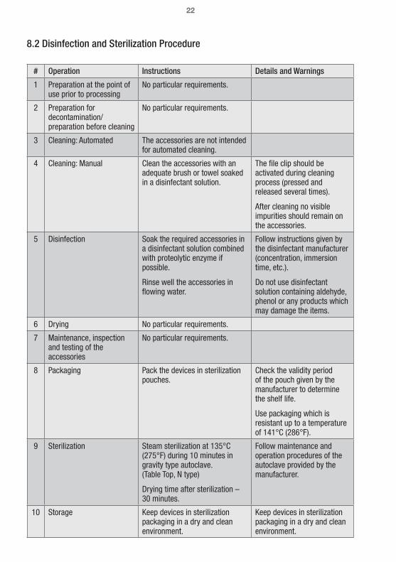
8.2 Disinfection and Sterilization Procedure
# Operation Instructions Details and Warnings
1 Preparation at the point of use prior to processing
No particular requirements.
2 Preparation for decontamination/ preparation before cleaning
No particular requirements.
3 Cleaning: Automated The accessories are not intended for automated cleaning.
4 Cleaning: Manual Clean the accessories with an adequate brush or towel soaked in a disinfectant solution.
The file clip should be activated during cleaning process (pressed and released several times).
After cleaning no visible impurities should remain on the accessories.
5 Disinfection Soak the required accessories in a disinfectant solution combined with proteolytic enzyme if possible.
Rinse well the accessories in flowing water.
Follow instructions given by the disinfectant manufacturer (concentration, immersion time, etc.).
Do not use disinfectant solution containing aldehyde, phenol or any products which may damage the items.
6 Drying No particular requirements.
7 Maintenance, inspection and testing of the accessories
No particular requirements.
8 Packaging Pack the devices in sterilization pouches.
Check the validity period of the pouch given by the manufacturer to determine the shelf life.
Use packaging which is resistant up to a temperature of 141°C (286°F).
9 Sterilization Steam sterilization at 135°C (275°F) during 10 minutes in gravity type autoclave. (Table Top, N type)
Drying time after sterilization – 30 minutes.
Follow maintenance and operation procedures of the autoclave provided by the manufacturer.
10 Storage Keep devices in sterilization packaging in a dry and clean environment.
Keep devices in sterilization packaging in a dry and clean environment.

23
9 Manufactured For VDW GmbHBayerwaldstr. 1581737 MunichGermany
Phone: +49- (0) 89-6 27 34-0Fax: +49- (0) 89-6 27 34-190Service: +49- (0) 89-6 27 34-555
Website: www.vdw-dental.comEmail: [email protected]
10 WarrantyIn addition to the warranty applicable under the sales contract with the dental dealer, DENTSPLY Tulsa Dental Specialties directly offers customers the following service warranty:
1. DENTSPLY Tulsa Dental Specialties guarantees proper manufacturing of the product, the use of top quality materials, performance of all required tests and adherence to all applicable pertinent laws and regulations relating to the product.The full functionality of ProMark® apex locator is covered by a 12 month warranty, beginning on the date of delivery to the customer (according to the shipping papers with the respective product serial number, issued by the seller at the time of purchase). Cables and battery are covered by a warranty period of 6 months. The customer is only entitled to warranty services within the warranty period and under the condition that DENTSPLY Tulsa Dental Specialties has been informed of the defect in writing within a two month period from the date of discovery of the defect.
2. This warranty covers only the exchange or repair of individual components or parts affected by manufacturing defects. The cost for personnel to be dispatched for purposes of technical assistance from the dealer to the customer, and/or packaging expenses of the customer will not be covered by DENTSPLY Tulsa Dental Specialties.
Any customer claims beyond the realm of repair, such as claims for damages, will not be covered.This warranty does not include any compensation for direct or indirect personal injuries or material damage of any kind.The customer will not be entitled to damages covering for downtime of the equipment.
3. The warranty does not extend to damage for which evidence can be provided by DENTSPLY Tulsa Dental Specialties that such damage has been caused by negligence on the part of the user as related to Directions for Use, particularly during battery charging or battery replacement. The warranty explicitly excludes any defects arising on the basis of:• Damage occurring during transportation to DENTSPLY Tulsa Dental Specialties for the purposes of repair.• Damage occurring through environmental events such as lightning strikes, fire and/or humidity.This warranty shall automatically become cancelled and void if the product has been improperly repaired, modified or manipulated in any manner by the user, by non-authorized persons or by third party personnel.
4. This warranty is valid only if the device sent for repair includes the invoice with confirmation of the product’s shipping date.
5. Legal claims, such as under product liability law or claims against suppliers from whom the customer has purchased the product, in particular the dental dealer, remain unaffected.
11 DisclaimerDENTSPLY Tulsa Dental Specialties, its representatives and dealers shall have no liability or responsibility for damages caused by the clinical use of their products, whether the use is accidentally associated with other electro-medical devices (e.g. pacemakers) or not.DENTSPLY Tulsa Dental Specialties, its representatives and dealers shall bear no liability or responsibility for damages caused by improper use of the device, not according to the Directions For Use.

24
INTERNALLY POWERED DEVICE NiMH rechargeable battery
PROTECTION AGAINST ELECTRIC SHOCK Type BF
LEVEL OF SAFETY IN PRESENCE OF INFLAMMA-BLE ANAESTHETIC MIXTURES OR OXYGEN
Not suitable for use in proximity of anaesthetic mixtures containing air, oxygen or nitrogen oxide
OPERATING MODE Continuous
PROTECTION AGAINST LIQUID PENETRATION No protection against ingress of liquids
TRANSPORTATION AND STORAGE CONDITIONS
Temperature range: –20 ºC to +60 ºC (4 °F to 140 °F) Relative humidity: 10 % to 90 %, non-condensingAtmospheric pressure: 50 kPa to 106 kPa
OPERATING CONDITIONS
Temperature range: +10 ºC to + 40 ºC (50 °F to 104 °F)Relative humidity: 10 % to 90 %, non-condensingAtmospheric pressure: 70 kPa to 106 kPa
DIMENSIONS
Folded:Width: 101 mm, Length: 110 mm, Thickness: 27 mmOpen: Width: 101 mm, Length: 110 mm, Height: 97 mm
WEIGHT 350 gr.
DISPLAY TYPE 3.5” Thin-film transistor color display with touch panel
DISPLAY / ACTIVE AREA 70 mm x 53 mm
EXTERNAL CHARGER Input: AC 100-240 V, 50/60 Hz
EXTERNAL CHARGER Output: 5 V DC, 1000 mA
12 Technical Data

25
Electromagnetic Compatibility
NOTES• The ProMark® requires special precautions with regard to electromagnetic compatibility.• It must be installed and prepared for use as described in section 7.4 “Operation”.• Certain types of RF wireless communication equipment such as mobile telephones arelikely to interfere with the ProMark®.• The recommended radiation levels of RF wireless communication equipment specified in this paragraph must therefore be complied with.• The ProMark® must not be used near or on top of another device. If this cannot beavoided, it is necessary – before clinical use – to check the equipment for correct operationunder the conditions of use.• The use of accessories other than those specified or sold by VDW as replacement parts may have the consequence of increasing the emissions or decreasing the immunity of the unit.
Electromagnetic Emissions
NOTES• ProMark® is intended for use in the professional healthcare facility or home healthcare electromagnetic environment specified in the tables below.• The user and/or installer of the unit must ensure that it is used in such an environment.
Guidance and Manufacturer's Declaration – Electromagnetic Emissions – ProMark®
The ProMark® is intended for use in professional healthcare facility or home healthcare electromagnetic environment specified below;The customer or the user of the ProMark® should assure that it is used in such an environment.
Emissions test Compliance Electromagnetic environment - guidance
RF emissions CISPR 11 Group 1
The ProMark® uses RF energy only for its internal function. Therefore, its RF emissions are very low and are not likely to cause any interference in nearby electronic equipment.
RF emissions CISPR 11 Class B
The ProMark® is suitable for use in professional healthcare facilities or domestic establishments.
Harmonic emissions IEC 61000-3-2 Not applicable
Voltage fluctuations/flicker emissions IEC 61000-3-3
Not applicable

26
Guidance and Manufacturer's Declaration – Electromagnetic Immunity – ProMark®
The ProMark® is intended for use in the electromagnetic environment specified below;The customer or the user of the ProMark® should assure that it is used in such an environment.
Immunity test IEC 60601-1-2 Test level Compliance level Electromagnetic environment
- guidance
Electrostatic discharge (ESD) IEC 61000-4-2
± 8 kV contact± 15 kV air
± 8 kV contact± 15 kV air
Floors should be wood, concrete or ceramic tile. If floors are covered with synthetic material, the relative humidity should be at least 30%.
Electrical fast transients / bursts, IEC 61000-4-4
± 2 kV for power supply lines± 1 kV for input/ output lines
± 2 kV for power supply linesNot Applicable
Mains power quality should be that of a typical public low-voltage power supply network that supplies buildings used for domestic purposes, commercial or hospital, clinic environment.
Surges IEC 61000-4-5
± 1 kV Line-to-line± 2 kV Line-to-ground
± 1 kV Line-to-line± 2 kV Line-to-ground
Mains power quality should be that of a typical public low-voltage power supply network that supplies buildings used for domestic purposes, commercial or hospital, clinic environment.
Voltage dips
Voltage interruptionsIEC 61000-4-11
0 % UT; 0.5 cycle
0 % UT; 1 cycle and 70% UT; 25/30 cycles
0% UT; 250/300 cycles
0 % UT; 0.5 cycle
0 % UT; 1 cycle and 70% UT; 25/30 cycles
0% UT; 250/300 cycles
Mains power quality should be that of a typical public low-voltage power supply network that supplies buildings used for domestic purposes, commercial or hospital, clinical environment. If the user of the ProMark® requires battery cha rging during power mains interruptions, it is recommended that ProMark® charger be powered from a separate power supply (UPS, etc.).
Rated power frequency magnetic fieldsIEC 61000-4-8
30 A/m50 or 60 Hz
30 A/m50 or 60 Hz
Power frequency magnetic fields should be at levels characteristic of a typical public low-voltage power supply network that supplies buildings used for domestic purposes, commercial or hospital, clinic environment.
NOTEUT is the a.c. mains voltage prior to application of the test level.

Guidance and Manufacturer's Declaration – Electromagnetic Immunity – ProMark®
The ProMark® is intended for use in the electromagnetic environment specified below;The customer or the user of the ProMark® should assure that it is used in such an environment.
Immunity test IEC 60601-1-2 Test level Compliance level Electromagnetic environment
- guidance
Conducted disturbances induced by RF fields IEC 61000-4-6
Radiated RF IEC 61000-4-3
3 Vrms150 kHz to 80 MHz
6 Vrms in ISM bands 150 kHz to 80 MHz80% AM at 1 kHz
10 V/m80 MHz to 2.7 GHz
3 Vrms150 kHz to 80 MHz
6 Vrms in ISM bands 150 kHz to 80 MHz80% AM at 1 kHz
10 V/m
Portable and mobile RF communications equipment should be used no closer to any part of the ProMark® , including cables, than the recommended separation distance calculated from the equation applicable to the frequency of the transmitter.Recommended separation distance:d = 1.17 from 150 kHz to 80 MHzd = 1.17 • from 80 MHz to 800 MHzd = 2.3 • from 800 MHz to 2.7 GHzWhere P is the maximum output power rating of the transmitter in watts (W) according to the transmitter manufacturer and d is the recommended separation distance in meters (m).Field strengths from fixed RF transmitters, as determined by an electromagnetic site surveya, should be less than the compliance level in each frequency rangeb.Interference may occur in the vicinity of equipment marked with the following symbol:
NOTES• At 80 MHz and 800 MHz, the higher frequency range applies.• These guidelines may not apply in all situations. Electromagnetic propagation is affected by absorption and reflection from structures objects and people.

28
aField strengths from fixed transmitters, such as base stations for radio (cellular/cordless) telephones and land mobile radios, amateur radio, AM and FM radio broadcast and TV broadcast cannot be predicted theoretically with accuracy. To assess the electromagnetic environment due to fixed RF transmitters, an electromagnetic site survey should be considered. If the measured field strength in the location in which the ProMark® is used exceeds the applicable RF compliance level above, the ProMark® should be observed to verify normal operation. If abnormal performance is observed, additional measures may be necessary, such as re-orienting or relocating the ProMark® .bOver the frequency range 150 kHz to 80 MHz, field strengths should be less than 3 V/m.
Specifications for enclosure port immunity to RF wireless communic ations equipmentThe ProMark® is intended for use in an electromagnetic environment in which radiated radiofrequency disturbances are controlled.The user and/or installer of the unit can help prevent electromagnetic interference by maintaining radiation levels of RF wireless communications equipment (emitters) within the compliance specified in the table below.
Recommended radiation levels of RF wireless Communications Equipment
Frequency band IEC 60601-1-2 Test level Compliance level Minimum separation
distance
380 – 390 MHz 27 V/m 27 V/m 0.3 m
430 – 470 MHz 28 V/m 28 V/m 0.3 m
704 – 787 MHz 9 V/m 9 V/m 0.3 m
800 – 960 MHz 28 V/m 28 V/m 0.3 m
1 700 – 1 990 MHz 28 V/m 28 V/m 0.3 m
2 400 – 2 570 MHz 28 V/m 28 V/m 0.3 m
5 100 – 5 800 MHz 9 V/m 9 V/m 0.3 m
NOTEThese guidelines may not apply in all situations. Electromagnetic propagation is affected by absorption and reflection from structures, objects, and people.

29

Manufactured For: VDW GmbH, Bayerwaldstr. 15 81737 Munich, Germany
Made in Israel
© DENTSPLY International, Inc. DFUPMKAL Rev. 2/02.10.2018
Distributed By:DENTSPLY Tulsa Dental SpecialtiesDENTSPLY International, Inc.608 Rolling Hills Drive Johnson City, TN 37604 1-800-662-1202 1-800-597-2779 (fax) www.DENTSPLY.comwww.DENTSPLY.com/endo-patents