Embed Size (px)
Citation preview

BA136D/06/en/04.10
71112144
Valid as of version
V 2.02.XX (device software)
Operating Instructions
Proline Prosonic Flow 93T Portable
Portable ultrasonic flow measuring system


Proline Prosonic Flow 93T Portable Table of contents
Endress+Hauser 3
Table of contents
1 Safety instructions . . . . . . . . . . . . . . . . 5
1.1 Designated use . . . . . . . . . . . . . . . . . . . . . . . . . . . . 5
1.2 Installation, commissioning and operation . . . . . . . . 5
1.3 Operational safety . . . . . . . . . . . . . . . . . . . . . . . . . . 5
1.4 Return . . . . . . . . . . . . . . . . . . . . . . . . . . . . . . . . . . . 6
1.5 Notes on safety conventions and icons . . . . . . . . . . . 6
2 Identification . . . . . . . . . . . . . . . . . . . . 7
2.1 Device designation . . . . . . . . . . . . . . . . . . . . . . . . . 7
2.1.1 Nameplate of the transmitter . . . . . . . . . . . . 7
2.1.2 Nameplate of the sensor . . . . . . . . . . . . . . . 8
2.2 Certificates and approvals . . . . . . . . . . . . . . . . . . . . 9
2.3 Registered trademarks . . . . . . . . . . . . . . . . . . . . . . . 9
3 Installation . . . . . . . . . . . . . . . . . . . . . 10
3.1 Incoming acceptance, transport and storage . . . . . . 10
3.1.1 Incoming acceptance . . . . . . . . . . . . . . . . . 10
3.1.2 Transport . . . . . . . . . . . . . . . . . . . . . . . . . 10
3.1.3 Storage . . . . . . . . . . . . . . . . . . . . . . . . . . . 10
3.2 Installation conditions . . . . . . . . . . . . . . . . . . . . . . 10
3.2.1 Dimensions . . . . . . . . . . . . . . . . . . . . . . . . 10
3.2.2 Mounting location . . . . . . . . . . . . . . . . . . . 10
3.2.3 Orientation . . . . . . . . . . . . . . . . . . . . . . . . 11
3.2.4 Inlet and outlet run . . . . . . . . . . . . . . . . . . 11
3.2.5 Sensor selection and arrangement . . . . . . . 12
3.3 Preparatory steps prior to installation . . . . . . . . . . . 13
3.4 Determining the necessary installation distances . . 13
3.4.1 Installation distances for Prosonic Flow P . . 13
3.5 Determining values for installation distances . . . . . 13
3.5.1 Determining installation distances via
local operation . . . . . . . . . . . . . . . . . . . . . . 13
3.5.2 Determining installation distances via
Applicator . . . . . . . . . . . . . . . . . . . . . . . . . 15
3.6 Mechanical preparation . . . . . . . . . . . . . . . . . . . . . 15
3.6.1 Mounting the sensor holder . . . . . . . . . . . . 16
3.6.2 Premounting the strapping bands
(metal, medium nominal diameters) . . . . . . 20
3.6.3 Premounting the strapping bands
(metal, large nominal diameters) . . . . . . . . 21
3.6.4 Mounting with strapping bands (flexible) . . 22
3.7 Installing Prosonic Flow P (DN 15 to 65 / ½ to 2½")23
3.7.1 Mounting the sensor . . . . . . . . . . . . . . . . . 23
3.8 Installing Prosonic Flow P
(DN 50 to 4000 / 2 to 160") (Clamp On) . . . . . . . 24
3.8.1 Installation for measurement via
one traverse . . . . . . . . . . . . . . . . . . . . . . . 24
3.8.2 Installation for measurement via
two traverses . . . . . . . . . . . . . . . . . . . . . . . 26
3.9 Installing sensor DDU18 . . . . . . . . . . . . . . . . . . . . 28
3.10 Installing sensor DDU20
(wall thickness measurement) . . . . . . . . . . . . . . . . 29
3.10.1 Method 1 . . . . . . . . . . . . . . . . . . . . . . . . . 29
3.10.2 Method 2 . . . . . . . . . . . . . . . . . . . . . . . . . 30
3.11 Post-installation check . . . . . . . . . . . . . . . . . . . . . . 30
4 Wiring . . . . . . . . . . . . . . . . . . . . . . . . . 31
4.1 Charging the NiMH storage battery . . . . . . . . . . . . 31
4.2 Connecting the connecting cable . . . . . . . . . . . . . . 31
4.3 Cable specification for connecting cable . . . . . . . . . 31
4.4 Potential equalization . . . . . . . . . . . . . . . . . . . . . . . 32
4.5 Degree of protection . . . . . . . . . . . . . . . . . . . . . . . 32
4.6 Post-connection check . . . . . . . . . . . . . . . . . . . . . . 32
5 Operation . . . . . . . . . . . . . . . . . . . . . . 33
5.1 Quick operation guide . . . . . . . . . . . . . . . . . . . . . . 33
5.2 Display and operating elements . . . . . . . . . . . . . . . 33
5.3 Brief guide to the function matrix . . . . . . . . . . . . . . 36
5.3.1 General notes . . . . . . . . . . . . . . . . . . . . . . 37
5.3.2 Enabling the programming mode . . . . . . . . 37
5.3.3 Disabling the programming mode . . . . . . . . 37
5.4 Error messages . . . . . . . . . . . . . . . . . . . . . . . . . . . . 38
5.4.1 Type of error . . . . . . . . . . . . . . . . . . . . . . . 38
5.4.2 Error message types . . . . . . . . . . . . . . . . . . 38
5.4.3 Confirming error messages . . . . . . . . . . . . . 39
5.5 Communication . . . . . . . . . . . . . . . . . . . . . . . . . . . 39
5.5.1 FieldCare . . . . . . . . . . . . . . . . . . . . . . . . . . 39
6 Commissioning . . . . . . . . . . . . . . . . . . 40
6.1 Function check . . . . . . . . . . . . . . . . . . . . . . . . . . . 40
6.2 Switching on the measuring device . . . . . . . . . . . . 40
6.2.1 Resetting the measuring device . . . . . . . . . 40
6.3 Commissioning via onsite display . . . . . . . . . . . . . . 41
6.3.1 Quick Setup "Sensor Installation" . . . . . . . . 41
6.3.2 Quick Setup "Commissioning" . . . . . . . . . . 43
6.3.3 Quick Setup "Pulsating Flow" . . . . . . . . . . . 44
6.4 Application-specific commissioning . . . . . . . . . . . . 47
6.4.1 Zero point adjustment . . . . . . . . . . . . . . . . 47
6.5 Using the data logger . . . . . . . . . . . . . . . . . . . . . . . 48
6.6 Data exchange with Prosonic Flow 93T . . . . . . . . . 48
7 Maintenance . . . . . . . . . . . . . . . . . . . . 49
7.1 General . . . . . . . . . . . . . . . . . . . . . . . . . . . . . . . . . 49
7.2 Charging the device . . . . . . . . . . . . . . . . . . . . . . . . 49
8 Accessories . . . . . . . . . . . . . . . . . . . . . 50
9 Troubleshooting . . . . . . . . . . . . . . . . . 52
9.1 Troubleshooting instructions . . . . . . . . . . . . . . . . . 52
9.2 System error messages . . . . . . . . . . . . . . . . . . . . . . 52
9.3 Process error messages . . . . . . . . . . . . . . . . . . . . . . 54
9.4 Process errors without messages . . . . . . . . . . . . . . 55
9.5 Response of outputs to errors . . . . . . . . . . . . . . . . . 56
9.6 Spare parts . . . . . . . . . . . . . . . . . . . . . . . . . . . . . . . 56
9.7 Return . . . . . . . . . . . . . . . . . . . . . . . . . . . . . . . . . . 56
9.8 Disposal . . . . . . . . . . . . . . . . . . . . . . . . . . . . . . . . . 56
9.9 Software history . . . . . . . . . . . . . . . . . . . . . . . . . . . 56

Proline Prosonic Flow 93T Portable Table of contents
4 Endress+Hauser
10 Technical data . . . . . . . . . . . . . . . . . . . 57
10.1 Quick technical data guide . . . . . . . . . . . . . . . . . . . 57
10.1.1 Application . . . . . . . . . . . . . . . . . . . . . . . . 57
10.1.2 Function and system design . . . . . . . . . . . . 57
10.1.3 Input . . . . . . . . . . . . . . . . . . . . . . . . . . . . . 57
10.1.4 Output . . . . . . . . . . . . . . . . . . . . . . . . . . . 58
10.1.5 Power supply . . . . . . . . . . . . . . . . . . . . . . . 58
10.1.6 Performance characteristics . . . . . . . . . . . . 59
10.1.7 Operating conditions: installation . . . . . . . . 60
10.1.8 Operating conditions: environment . . . . . . 61
10.1.9 Operating conditions: process . . . . . . . . . . 62
10.1.10 Mechanical construction . . . . . . . . . . . . . . 62
10.1.11 Human interface . . . . . . . . . . . . . . . . . . . 63
10.1.12 Certificates and approvals . . . . . . . . . . . . 64
10.1.13 Ordering information . . . . . . . . . . . . . . . . 64
10.1.14 Documentation . . . . . . . . . . . . . . . . . . . . 64
11 Description of Device Functions . . . . . 65
11.1 Function matrix . . . . . . . . . . . . . . . . . . . . . . . . . . . 65
11.1.1 General layout of the function matrix . . . . . 65
11.1.2 Codes identifying cells . . . . . . . . . . . . . . . . 66
11.2 Function matrix of Prosonic Flow 93T Portable . . . 67
11.3 Block MEASURED VARIABLES . . . . . . . . . . . . . . 68
11.3.1 Group MEASURING VALUES´ . . . . . . . . . . 68
11.3.2 Group SYSTEM UNITS . . . . . . . . . . . . . . . 69
11.3.3 Group SPECIAL UNITS . . . . . . . . . . . . . . 71
11.4 Block QUICK SETUP . . . . . . . . . . . . . . . . . . . . . . 71
11.5 Block USER INTERFACE . . . . . . . . . . . . . . . . . . 72
11.5.1 Group CONTROL . . . . . . . . . . . . . . . . . . . 72
11.5.2 Group MAIN LINE . . . . . . . . . . . . . . . . . 75
11.5.3 Group ADDITIONAL LINE . . . . . . . . . . . . 77
11.5.4 Group INFORMATION LINE . . . . . . . . . 81
11.6 Block TOTALIZER . . . . . . . . . . . . . . . . . . . . . . . . 85
11.6.1 Group TOTALIZER (1 to 3) . . . . . . . . . . . 85
11.6.2 Group HANDLING TOTALIZER . . . . . . . . 86
11.7 Block OUTPUTS . . . . . . . . . . . . . . . . . . . . . . . . . . 87
11.7.1 Group DATA LOGGER . . . . . . . . . . . . . . . 87
11.8 Block INPUTS . . . . . . . . . . . . . . . . . . . . . . . . . . . 88
11.8.1 Group CURRENT INPUT . . . . . . . . . . . . . 88
11.9 Block BASIC FUNCTIONS . . . . . . . . . . . . . . . . . . 90
11.9.1 Group PROCESS PARAMETER . . . . . . . . . 90
11.9.2 Group SYSTEM PARAMETER . . . . . . . . . . 98
11.9.3 Group SENSOR DATA . . . . . . . . . . . . . . 99
11.10 Block SUPERVISION . . . . . . . . . . . . . . . . . . . . . 102
11.10.1 Group SYSTEM . . . . . . . . . . . . . . . . . . . 102
11.10.2 Group VERSION INFO . . . . . . . . . . . . . 104
12 Factory settings . . . . . . . . . . . . . . . . . 106
12.1 SI units (not for USA and Canada) . . . . . . . . . . . . 106
12.1.1 Units of length and temperature . . . . . . . . 106
12.1.2 Language . . . . . . . . . . . . . . . . . . . . . . . . 106
12.2 US units (for USA and Canada only) . . . . . . . . . . . 106
12.2.1 Units of length and temperature . . . . . . . 106
12.2.2 Language . . . . . . . . . . . . . . . . . . . . . . . . 106
Index . . . . . . . . . . . . . . . . . . . . . . . . . . . . . 107

Proline Prosonic Flow 93T Portable Safety instructions
Endress+Hauser 5
1 Safety instructions
1.1 Designated use
The measuring device described in these Operating Instructions is to be used only for measuring the
flow rate of liquids in closed pipes.
Examples:
• Acids, alkalis, paints, oils
• Liquid gas
• Ultrapure water with low conductivity, water, wastewater
As well as measuring the volume flow, the sound velocity of the fluid is also always measured.
Different fluids can be distinguished or the fluid quality can be monitored.
The designated operation of the measuring device is battery operation without connection to the
charger.
Resulting from incorrect use or from use other than that designated the operational safety of the
measuring devices can be suspended. The manufacturer accepts no liability for damages being
produced from this.
1.2 Installation, commissioning and operation
Note the following points:
• Installation, connection to the electricity supply, commissioning and maintenance of the device
must be carried out by trained, qualified specialists authorized to perform such work by the
facility's owner-operator.
The specialist must have read and understood these Operating Instructions and must follow the
instructions they contain.
• The device must be operated by persons authorized and trained by the facility's owner-operator.
Strict compliance with the instructions in these Operating Instructions is mandatory.
• Endress+Hauser is willing to assist in clarifying the chemical resistance properties of parts wetted
by special fluids, including fluids used for cleaning.
However, small changes in temperature, concentration or the degree of contamination in the
process can result in changes to the corrosion resistance properties. Therefore, Endress+Hauser
cannot guarantee or accept liability for the corrosion resistance properties of wetted materials in
a specific application.
The user is responsible for choosing suitable wetted materials in the process.
• The storage batteries for the device may only be charged with the charger supplied. Other
equipment could cause the battery to overheat (risk of fire!).
• Invariably, local regulations governing the opening and repair of electrical devices apply.
1.3 Operational safety
Note the following points:
• The transmitter having the ingress protection IP 40 is intended for operation in dry, clean and
non-hazardous environment. Mechanical stresses are to be avoided.
• The measuring device complies with the general safety requirements in accordance with
EN 61010-1 and the EMC requirements of IEC/EN 61326 during storage battery operation.
• The manufacturer reserves the right to modify technical data without prior notice. Your
Endress+Hauser distributor will supply you with current information and updates to these
Operating Instructions.

Safety instructions Proline Prosonic Flow 93T Portable
6 Endress+Hauser
1.4 Return
The following procedures must be carried out before a flowmeter requiring repair or calibration, for
example, is returned to Endress+Hauser:
• Always enclose a duly completed "Declaration of Contamination" form.
Only then Endress+Hauser can transport, examine and repair a returned device.
! Note!
You will find a preprinted "Declaration of Contamination" form at the back of this manual.
• Enclose special handling instructions if necessary, for example a safety data sheet as per
EC REACH Regulation No. 1907/2006.
• Remove all residues. Pay special attention to the grooves for seals and crevices which could
contain residues. This is particularly important if the substance is hazardous to health, e.g.
flammable, toxic, caustic, carcinogenic, etc.
# Warning!
• Do not return a measuring device if you are not absolutely certain that all traces of hazardous
substances have been removed, e.g. substances which have penetrated crevices or diffused
through plastic.
• Costs incurred for waste disposal or injury (burns, etc.) due to inadequate cleaning will be charged
to the owner-operator.
1.5 Notes on safety conventions and icons
The devices can, however, be a source of danger if used incorrectly or for anything other than the
designated use. Consequently, always pay particular attention to the safety instructions indicated in
these Operating Instructions by the following icons:
The devices are designed to meet state-of-the-art safety requirements, have been tested, and left the
factory in a condition in which they are safe to operate. The devices comply with the applicable
standards and regulations in accordance with EN 61010-1 "Safety requirements for electrical
equipment for measurement, control and laboratory use".
# Warning!
"Warning" indicates an action or procedure which, if not performed correctly, can result in injury
or a safety hazard. Comply strictly with the instructions and proceed with care.
" Caution!
"Caution" indicates an action or procedure which, if not performed correctly, can result in incorrect
operation or destruction of the device. Comply strictly with the instructions.
! Note!
"Note" indicates an action or procedure which, if not performed correctly, can have an indirect
effect on operation or trigger an unexpected response on the part of the device.

Proline Prosonic Flow 93T Portable Identification
Endress+Hauser 7
2 Identification
2.1 Device designation
The "Prosonic Flow 93T" flowmeter system consists of the following components:
• Prosonic Flow 93 transmitter
• Sensor:
– Prosonic Flow P Clamp On version (DN 15 to 65 / ½ to 2½")
– Prosonic Flow P Clamp On version (DN 50 to 4000 / 2 to 160")
The transmitter and the sensor are connected by a cable.
2.1.1 Nameplate of the transmitter
A0011554
Fig. 1: Nameplate specifications for the "Prosonic Flow 93T" transmitter (example)
1 Order code/serial number: See the specifications on the order confirmation for the meanings of the individual
letters and digits
2 Power supply/power consumption
3 Permitted ambient temperature range
4 Degree of protection
1
Prosonic Flow 93T Portable
Order Code:
Ser.No.:
93TA1-XXXXXXXXXX
0°C(+32°F) <Tamb< +60°C(+140°F)
12V DC
1234567890
IP40
Ident No.: XXXXXXXXXXXXXXX
1.5 A
i
2
3
4

Identification Proline Prosonic Flow 93T Portable
8 Endress+Hauser
2.1.2 Nameplate of the sensor
A0011555
Fig. 2: Nameplate specifications for the "Prosonic Flow P" sensor (example)
A Sensor DN 50 to 300 (2 to 12") and DN 100 to 4000 (4 to 160")
B Sensor DN 15 to 65 (½ to 2½")
1 Order code/serial number: See the specifications on the order confirmation for the meanings of the individual
letters and digits
2 Sensor type
3 Nominal diameter range
4 Max. fluid temperature
5 Degree of protection
6 Permitted ambient temperature range
7 Flow direction
Prosonic Flow P Portable
Type:
TM:
IP68 / NEMA/Type 6P
P-CL-6F-M-D
-40...+100°C/-40...+32°F
Ser.No.: 123456789011
2
4
5
7
B
1
23
6
5
A
Ser.No.:
Type:
TM:DN50-300
P-CL-2F-L-B
Order Code: 93TA1-XXXXXXXXXXXX
Prosonic Flow PProsonic Flow P
CH1
-40°C(-40°F)...+80°C(+175°F)
12345678901i
41
53
Re
ina
ch
,S
witze
rla
nd
EN
DR
ES
S+
HA
US
ER
TYPE 6P
NEMA
IP68
Tamb/Tumg:0°C..+60°C Warn
ing:To
main
tain
Type/N
EM
A6p
or
IP68
pro
tection
the
connecto
rm
ustbe
fully
engaged.
4153 ReinachSwitzerland
OPEN CLOSE4

Proline Prosonic Flow 93T Portable Identification
Endress+Hauser 9
2.2 Certificates and approvals
The devices are designed in accordance with good engineering practice to meet state-of-the-art
safety requirements, have been tested, and left the factory in a condition in which they are safe to
operate.
The devices comply with the applicable standards and regulations in accordance with EN 61010-1
"Safety requirements for electrical equipment for measurement, control and laboratory use" and
with the EMC requirements of IEC/EN 61326.
The measuring system described in these Operating Instructions thus complies with the statutory
requirements of the EC Directives. Endress+Hauser confirms successful testing of the device by
affixing to it the CE mark.
The measuring system complies with the EMC requirements of the "Australian Communications
and Media Authority (ACMA)".
2.3 Registered trademarks
HART ®
Registered trademark of HART Communication Foundation, Austin, USA.
FieldCare®, Applicator®
Registered or registration-pending trademarks of Endress+Hauser Flowtec AG, Reinach, CH.

Installation Proline Prosonic Flow 93T Portable
10 Endress+Hauser
3 Installation
3.1 Incoming acceptance, transport and storage
3.1.1 Incoming acceptance
On receipt of the goods, check the following points:
• Check the packaging and the contents for damage.
• Check the shipment, make sure nothing is missing and that the scope of supply matches your
order.
3.1.2 Transport
The devices must be transported in the container supplied when transporting them to the measuring
point.
3.1.3 Storage
• Pack the measuring device in such a way as to protect it reliably against impact for storage (and
transportation). The original packaging provides optimum protection.
• The storage temperature corresponds to the ambient temperature range of the transmitter, the
sensors and the corresponding sensor cables (→ ä 61).
• The measuring device must be protected against direct sunlight during storage in order to avoid
unacceptably high surface temperatures.
3.2 Installation conditions
3.2.1 Dimensions
The dimensions and lengths of the sensor and transmitter are provided in the separate "Technical
Information" document on the device in question. This can be downloaded as a PDF file from
www.endress.com.
A list of the "Technical Information" documents available is provided on → ä 64.
3.2.2 Mounting location
Correct flow measurement is possible only if a pipe is full. Entrained air or gas bubbles forming in
the pipe can result in an increase in measuring errors.
For this reason avoid the following mounting locations in the pipe:
• Highest point of a pipeline. Risk of air accumulating.
• Directly upstream of a free pipe outlet in a vertical pipeline.
A0001103
Fig. 3: Mounting location

Proline Prosonic Flow 93T Portable Installation
Endress+Hauser 11
3.2.3 Orientation
Vertical
We recommend the sensor be mounted where there is upward direction of flow. With this
orientation, entrained solids will sink down and gases will rise away from the sensor when the fluid
is stagnant.
Horizontal
We recommend the sensors be mounted within an angle of ±60° to the horizontal (area shaded gray
in the graphic). With this orientation, flow measurement is less affected by any gas or air
accumulation in the upper area of the pipe or by buildup at the bottom of the pipe.
A0001105
Fig. 4: Recommended orientation and recommended installation range
A Recommended orientation with upward direction of flow
B Recommended installation range with horizontal orientation
C Recommended installation range max. 120°
3.2.4 Inlet and outlet run
If possible, install the sensor well clear of assemblies such as valves, T-pieces, elbows, etc.
Compliance with the following inlet and outlet runs is required in order to ensure measuring
accuracy.
A0013459
Fig. 5: Inlet and outlet run
1 Valve (2/3 open)
2 Pump
3 Two pipe bends in different directions
A
B
C C
� 15 x DN
� 20 x DN
� 20 x DN
� 15 x DN
� 3 x DN
1
2
3

Installation Proline Prosonic Flow 93T Portable
12 Endress+Hauser
3.2.5 Sensor selection and arrangement
The sensors can be arranged differently:
• Mounting arrangement for measurement via one traverse: the sensors are located on opposite
sides of the pipe.
• Mounting arrangement for measurement via two traverses: the sensors are located on the same
side of the pipe.
A0001108
Fig. 6: Sensor mounting arrangement
A Mounting arrangement for measurement via one traverse
B Mounting arrangement for measurement via two traverses
The number of traverses required depends on the sensor type, the nominal diameter and the
thickness of the pipe wall. We recommend the following types of mounting:
BA
Sensor Type Nominal Diameter Sensor Frequency Sensor ID Type of Mounting 1)
Prosonic Flow P
DN 15 to 65 (½ to 2½") 6 MHz P-CL-6F* 2 (or 1) traverses
DN 50 to 65 (2 to 2½") 6 MHz (or 2 MHz)P-CL-6F*
P-CL-2F*2 (or 1) traverses 2)
DN 80 (3") 2 MHz P-CL-2F* 2 traverses
DN 100 to 300 (4 to 12") 2 MHz (or 1 MHz)P-CL-2F*
P-CL-1F*2 traverses 3)
DN 300 to 600 (12 to 24") 1 MHz (or 2 MHz)P-CL-1F*
P-CL-2F*2 traverses 3)
DN 650 to 4000 (26 to 160") 1 MHz (or 0.5 MHz)P-CL-1F*
W-CL-05F*1 traverse 3)
1) The installation of clamp-on sensors is principally recommended in the 2 traverse type installation. This type of
installation allows the easiest and most comfortable type of mounting and means that a system can also be mounted
even if the pipe can only be accessed from one side. However, in certain applications a 1 traverse installation may be
preferred. These include:
• Certain plastic pipes with wall thickness > 4 mm (0.16")
• Pipes made of composite materials such as GRP
• Lined pipes
• Applications with fluids with high acoustic damping
2) If the pipe nominal diameter is small (DN 65 / 2½" and smaller), the sensor spacing with Prosonic Flow P can be too
small for two traverse installation using sensor P-CL-2F*. In this case, the 1 traverse type of installation must be used.
3) 0.5 MHz sensors (Prosonic Flow W) are also recommended for applications with composite material pipes such as
GRP and may be recommended for certain lined pipes, pipes with wall thickness > 10 mm (0.4"), or applications with
media with high acoustic damping. In addition, for these applications we principally recommend mounting the
W sensors in a 1 traverse configuration.

Proline Prosonic Flow 93T Portable Installation
Endress+Hauser 13
3.3 Preparatory steps prior to installation
Depending on the conditions specific to the measuring point (e.g. Clamp On, number of traverses,
fluid, etc.), a number of preparatory steps have to be taken before actually installing the sensors:
1. Determination of the values for the necessary installation distances based on the conditions
specific to the measuring point. A number of methods are available for determining the values:
– Local operation of the device
– Applicator (software), online on the Endress+Hauser Internet site
2. Mechanical preparation of the Clamp On holders for the sensors:
– Mount the sensor holder (DN 15 to 65 / ½ to 2½")
– Premount the strapping bands (DN 50 to 200 / 2 to 8") or (DN 250 to 4000 / 10 to 160")
3.4 Determining the necessary installation distances
The installation distances that have to be maintained depend on:
• The type of sensor: Prosonic Flow P DN 50 to 4000 (2 to 160") or DN 15 to 65 (½ to 2½")
• The type of mounting: Clamp On with strapping band
• Number of traverses or single-path/dual-path version
3.4.1 Installation distances for Prosonic Flow P
3.5 Determining values for installation distances
3.5.1 Determining installation distances via local operation
Perform the following steps to determine the installation distances:
1. Connect and switch on the transmitter.
2. Run the "Sensor Installation" Quick Setup menu.
Connecting and switching on the transmitter
A0011547
Fig. 7: Connecting and switching on the transmitter
1 On/off switch (press switch ≥ 3 seconds)
2 Charger connection (different adapters are available for the connection)
DN 50 to 4000 (2 to 160") DN 15 to 65 (½ to 2½")
1 traverse 2 traverses 1 traverse 2 traverses
SENSOR DISTANCE SENSOR DISTANCE SENSOR DISTANCE*
WIRE LENGTH POSITION SENSOR POSITION SENSOR*
* In the SENSOR DISTANCE function, the distance is indicated in millimeters. The POSITION SENSOR function displays
the values for using the mounting rail (e.g. A3).
DATA
mA IN
12V DC SERVICE CH-UP CH-DN
1
2

Installation Proline Prosonic Flow 93T Portable
14 Endress+Hauser
Running the "Sensor Installation" Quick Setup menu
! Note!
• If you are not familiar with the operation of the device → ä 33.
• The following section only describes the steps necessary for Clamp On type of mounting within
the "Sensor Installation" Quick Setup.
Running the Quick Setup for Clamp On type of mounting
1. Enter or select installation-specific values or the values specified here.
2. Read off the installation distances necessary for mounting.
Subsequent procedure
The sensors can be installed once the installation distances have been determined:
• Prosonic Flow P (DN 15 to 65 / ½ to 2½")→ ä 23
• Prosonic Flow P (DN 50 to 4000 / 2 to 160")→ ä 24
Home position → Quick Setup → Setup sensor
↓
Language
QS sensor units
Clamp On → Measurement
Sensor type
1 or 2 → Sensor configuration = Number of traverses
Pipe standard
Nominal diameter
Pipe material
Sound velocity pipe
Pipe diameter
Circumference
Wall thickness
Liquid Installation
distances for
measurement via
one traverse:
Installation
distances for
measurement via
two traverses:
Temperature
Sound velocity liquid
Position sensor → –
Wire length → –
Sensor distance →
No → Other measurement?
↓
Setup sensor

Proline Prosonic Flow 93T Portable Installation
Endress+Hauser 15
3.5.2 Determining installation distances via Applicator
Applicator is a software application for selecting and planning flowmeters. The installation distances
required for installation can be determined without having to connect the transmitter beforehand.
Applicator is available:
• On a CD-ROM for installation on a local PC → ä 51.
• Via the Internet for direct online entry → www.endress.com → select country.
On the Internet site, select → Instruments → Flow → Tooling → Applicator. In the "Applicator
Sizing Flow" field, select the "Start Applicator Sizing Flow online" link.
Determining installation distances for Clamp On, measuring via one traverse
Determine the installation distances required via Applicator:
• Select the fluid.
• Select the device (e.g. 93P Clamp On).
• Enter or select measuring point-specific values.
• Select the number of traverses: 1
• Read off the necessary installation distances:
– Wire length: __________
– Sensor distance: __________
Subsequent procedure
The mechanical preparation tasks can be performed once the installation distances have been
determined → ä 15.
Determining installation distances for Clamp On, measuring via two traverses
Determine the installation distances required via Applicator:
• Select the fluid.
• Select the device (e.g. 93P Clamp On).
• Enter or select measuring point-specific values.
• Select the number of traverses: 2
• Read off the necessary installation distances:
– Sensor position: __________
– Sensor distance: __________
Subsequent procedure
The mechanical preparation tasks can be performed once the installation distances have been
determined → ä 15
3.6 Mechanical preparation
The way in which the sensors are secured differs on account of the pipe nominal diameter and the
sensor type. Depending on the type of sensor, users also have the option of securing the sensors with
strapping bands or screws such that they can be later removed, or permanently fixing the sensors in
place with welded bolts or welded holders.
Overview of possible ways to secure the various sensors:
Sensor For the measuring range Pipe nominal diameter Secured by
P DN 15 to 65 (½ to 2½") DN 15 to 65 (½ to 2½") Sensor holder → ä 23
P DN 50 to 4000 (2 to 160")
DN ≤ 200 (8") Strapping bands
(metal, medium nominal diameters)
→ ä 20
DN > 200 (8") Strapping bands
(metal, large nominal diameters)
→ ä 21
DN 50 to 4000 (2 to 160") Mounting with strapping bands (flexible) → ä 22

Installation Proline Prosonic Flow 93T Portable
16 Endress+Hauser
3.6.1 Mounting the sensor holder
• Sensor: Prosonic Flow (DN 15 to 65 / ½ to 2½")
• Sensor holder: Model 1 or 2
Model 1
1. Set the sensor distance determined (e.g. A19) on the sensor holder.
– Release the screws of the sensor holders.
– Position the sensor holders with the aid of the mounting rail.
– Tighten the screws of the sensor holders again.
A0011548
Fig. 8: Setting the sensor distance with the mounting rail (value from POSITION SENSOR function)
A Sensor distance for measurement via one traverse
B Sensor distance for measurement via two traverses
2. Guide the sensor holder over the pipe.
A0011549
Fig. 9: Setting the sensor holder on the pipe
A B C D E F G H I K 1 3 5 7 9 11 13 15 17 19 21 23 25 27 A B C D E F G H I K 1 3 5 7 9 11 13 15 17 19 21 23 25 27
A B
A B C D E F 1 3 5 7 9

Proline Prosonic Flow 93T Portable Installation
Endress+Hauser 17
3. Release the screw of the retaining bracket (a) and push the retaining bracket up against the
pipe.
A0011550
Fig. 10: Guiding the retaining bracket onto the pipe
a Screw of retaining bracket
4. Fix the sensor holder in place by:
– Tightening the screw of the retaining bracket (a)
– Tightening the tensioning screw (b)
# Warning!
Risk of damaging plastic or glass pipes if the screws are tightened too much! The use of a metal
half-shell is recommended (on the opposite side of the tensioning screw) when working with
plastic or glass pipes.
A0011551
Fig. 11: Fixing the sensor holder
a Screw of retaining bracket
b Tensioning screw
a
a
b

Installation Proline Prosonic Flow 93T Portable
18 Endress+Hauser
Model 2
1. Set the sensor distance determined (e.g. C9) on the sensor holder.
– Position the sensor holders with the aid of the mounting rail.
A0013546
Fig. 12: Setting the sensor distance with the mounting rail (value from POSITION SENSOR function)
A Sensor distance for measurement via one traverse
B Sensor distance for measurement via two traverses
2. Guide the sensor holder over the pipe.
A0013542
Fig. 13: Setting the sensor holder on the pipe
A B
K I H G F E
K I H G F E D C B A
27 25 23
27. 25 . 23 . 21. 19 . 17 .15 . 13 . 11 . 9 . 7 . 5 . 3 . 1 K I H G F E D C B A27. 25 . 23 . 21. 19 . 17 .15 . 13 . 11 . 9 . 7 . 5 . 3 . 1

Proline Prosonic Flow 93T Portable Installation
Endress+Hauser 19
3. Release the quick release of the retaining bracket (a) and push the retaining bracket up against
the pipe.
A0013543
Fig. 14: Guiding the retaining bracket onto the pipe
a Quick release of retaining bracket
4. Fix the sensor holder in place by:
– Tightening the quick release of the retaining bracket (a)
– Tightening the quick release (b)
A0013544
Fig. 15: Fixing the sensor holder
a Quick release of retaining bracket
b Quick release
a
a
b

Installation Proline Prosonic Flow 93T Portable
20 Endress+Hauser
3.6.2 Premounting the strapping bands (metal, medium nominal
diameters)
When mounting on a pipe with a nominal diameter of DN ≤ 200 (8").
Sensor: Prosonic Flow P (DN 50 to 4000 / 2 to 160")
! Note!
Sensor orientation shown in the following sketches is for visual purposes only.
Please apply the recommended orientation → ä 11.
Procedure
First strapping band
1. Fit the mounting bolt over the strapping band.
2. Wrap the strapping band around the pipe without twisting it.
3. Guide the end of the strapping band through the strapping band lock (tensioning screw is
pushed up).
4. Tighten the strapping band as tight as possible by hand.
5. Set the strapping band to the desired position.
6. Push down the tensioning screw and tighten the strapping band so that it cannot slip.
Second strapping band
7. Proceed as for the first strapping band (steps 1 to 7). Only slightly tighten the second strapping
band for final mounting. It must be possible to move the strapping band for final alignment.
Both strapping bands
8. Where necessary, shorten the strapping bands and trim the cut edges.
# Warning!
Risk of injury. To avoid sharp edges, trim the cut edges after shortening the strapping bands.
A0001109
Fig. 16: Premounting strapping bands for pipe diameters DN ≤ 200 (8")
1 Mounting bolt
2 Strapping band
3 Tensioning screw
1
2
3

Proline Prosonic Flow 93T Portable Installation
Endress+Hauser 21
3.6.3 Premounting the strapping bands (metal, large nominal
diameters)
When mounting on a pipe with a nominal diameter of DN > 200 (8").
Sensor: Prosonic Flow P (DN 50 to 4000 / 2 to 160")
Procedure
1. Measure the pipe circumference.
2. Shorten the strapping bands to one length (pipe circumference + 10 cm / 3.94") and trim the
cut edges.
# Warning!
Risk of injury. To avoid sharp edges, trim the cut edges after shortening the strapping bands.
First strapping band
3. Fit the centering plate along with the mounting bolt over the strapping band.
4. Wrap the strapping band around the pipe without twisting it.
5. Guide the end of the strapping band through the strapping band lock (tensioning screw is
pushed up).
6. Tighten the strapping band as tight as possible by hand.
7. Set the strapping band to the desired position.
8. Push down the tensioning screw and tighten the strapping band so that it cannot slip.
Second strapping band
9. Proceed as for the first strapping band (steps 3 to 8). Only slightly tighten the second strapping
band for final mounting. It must be possible to move the strapping band for final alignment.
A0001110
Fig. 17: Premounting strapping bands for pipe diameters DN > 200 (8")
1 Centering plate with mounting bolt
2 Strapping band
3 Tensioning screw
1
2
3

Installation Proline Prosonic Flow 93T Portable
22 Endress+Hauser
3.6.4 Mounting with strapping bands (flexible)
For sensor Prosonic Flow P (DN 50 to 4000 / 2 to 160")
" Caution!
• Each time you use the strapping bands, check that the ratchet locks and springs function safely
beforehand.
• Inspect the strapping bands for damage.
Procedure
Closing the strapping band lock
1. Fit the mounting bolt onto the strapping band.
2. Guide the strapping band around the pipe making sure it is not twisted in the process and, with
the ratchet lock (a) open, push the end through the slot. Pretension manually by pulling on the
free end of the strapping band.
! Note!
If you do not pretension the bands it is more difficult to release the strapping bands.
3. Tension continuously by moving the lever back and forth (b) until the strapping band is
optimally tensioned.
4. Then push down the lever (c).
" Caution!
The tensioning clamp (d) must engage on both sides!
Opening the strapping band lock
1. Pull back the lever lock (e) while simultaneously opening the lever 180° (f) until the lever lock
(g) is engaged.
2. Remove the strapping band.
A0011556.
Fig. 18: Strapping band lock
1 Closing the strapping band lock
2 Opening the strapping band lock
g
ab
c f e
d
g
21

Proline Prosonic Flow 93T Portable Installation
Endress+Hauser 23
3.7 Installing Prosonic Flow P (DN 15 to 65 / ½ to 2½")
3.7.1 Mounting the sensor
Prerequisites
• The sensor holder is already mounted → ä 16.
• The distance of the sensor holder is set (sensor distance) → ä 16.
Material
The following material is needed for mounting:
• Sensor
• Connecting cable
! Note!
Prior to mounting, connect the connecting cables to the sensors.
Procedure
1. Coat the contact surfaces (1) of the sensors with an even layer of coupling fluid
approx. 1 mm (0.04") thick.
A0013624
Fig. 19: Coating with coupling fluid
2. Mount as illustrated in the graphic (steps 1 to 5):
This completes the mounting process. The sensors can now be connected to the transmitter via the
connecting cables → ä 31.
1
A0011552
Fig. 20: Mounting the sensors,
Sensor holder: Model 1
A0013551
Fig. 21: Mounting the sensors,
Sensor holder: Model 2
1 2
3
4 5
1 2
3
4 5

Installation Proline Prosonic Flow 93T Portable
24 Endress+Hauser
3.8 Installing Prosonic Flow P (DN 50 to 4000 / 2 to 160")
(Clamp On)
3.8.1 Installation for measurement via one traverse
Prerequisites
• The installation distances (sensor distance and wire length) are known → ä 13.
• The strapping bands are already mounted → ä 15.
Material
The following material is needed for mounting:
• Two strapping bands incl. mounting bolts and centering plates where necessary
(already mounted → ä 15)
• Two measuring wires, each with a cable lug and a fixer to position the strapping bands
• Two sensor holders
• Coupling fluid for an acoustic connection between the sensor and pipe
• Two sensors incl. connecting cables
Procedure
1. Prepare the two measuring wires:
– Arrange the cable lugs and fixer such that the distance they are apart corresponds to the wire
length (SL).
– Screw the fixer onto the measuring wire.
A0001112
Fig. 22: Fixer (a) and cable lugs (b) at a distance that corresponds to the wire length (SL)
2. With the first measuring wire:
– Fit the fixer over the mounting bolt of the strapping band that is already securely mounted.
– Run the measuring wire clockwise around the pipe.
– Fit the cable lug over the mounting bolt of the strapping band that can still be moved.
3. With the second measuring wire:
– Fit the cable lug over the mounting bolt of the strapping band that is already securely
mounted.
– Run the measuring wire counterclockwise around the pipe.
– Fit the fixer over the mounting bolt of the strapping band that can still be moved.
4. Take the still movable strapping band, incl. the mounting bolt, and move it until both
measuring wires are evenly tensioned and tighten the strapping band so that it cannot slip.
A0001113
Fig. 23: Positioning the strapping bands (steps 2 to 4)
1 2 3 4 5 6 7 8 9 10 11
SL

Proline Prosonic Flow 93T Portable Installation
Endress+Hauser 25
5. Loosen the screws of the fixers on the measuring wires and remove the measuring wires from
the mounting bolt.
6. Fit the sensor holders over the individual mounting bolts and tighten securely with the
retaining nut.
A0001114
Fig. 24: Mounting the sensor holders
7. Coat the contact surfaces of the sensors with an even layer of coupling fluid
approx. 1 mm (0.04") thick, going from the groove through the center to the opposite edge.
A0011373
Fig. 25: Coating the contact surfaces of the sensor with coupling fluid
8. Insert the sensor into the sensor holder.
9. Fit the sensor cover on the sensor holder and turn until:
– The sensor cover engages with a click.
– The arrows (Å / Æ "close") are pointing towards one another.
10. Screw the connecting cable into the individual sensor.
A0001115
Fig. 26: Mounting the sensor and connecting the connecting cable
This completes the mounting process. The sensors can now be connected to the transmitter via the
connecting cables → ä 31.

Installation Proline Prosonic Flow 93T Portable
26 Endress+Hauser
3.8.2 Installation for measurement via two traverses
Prerequisites
• The installation distance (position sensor) is known → ä 13.
• The strapping bands are already mounted → ä 15.
Material
The following material is needed for mounting:
• Two strapping bands incl. mounting bolts and centering plates where necessary
(already mounted → ä 15)
• A mounting rail to position the strapping bands
• Two mounting rail holders
• Two sensor holders
• Coupling fluid for an acoustic connection between the sensor and pipe
• Two sensors incl. connecting cables
Mounting rail and POSITION SENSOR installation distance
The mounting rail has two rows with bores. The bores in one of the rows are indicated by letters
and the bores in the other row are indicated by numerical values. The value determined for the
POSITION SENSOR installation distance is made up of a letter and a numerical value.
The bores that are identified by the specific letter and numerical value are used to position the
strapping bands.
Procedure
1. Position the strapping bands with the aid of the mounting rail.
– Slide the mounting rail with the bore identified by the letter from POSITION SENSOR over
the mounting bolt of the strapping band that is permanently fixed in place.
– Position the movable strapping band and slide the mounting rail with the bore identified by
the numerical value from POSITION SENSOR over the mounting bolt.
A0001116
Fig. 27: Determining the distance in accordance with the mounting rail (e.g. POSITION SENSOR G22)
2. Tighten the strapping band so that it cannot slip.
3. Remove the mounting rail from the mounting bolt.
4. Fit the sensor holders over the individual mounting bolts and tighten securely with the
retaining nut.
G
22

Proline Prosonic Flow 93T Portable Installation
Endress+Hauser 27
A0001117
Fig. 28: Mounting the sensor holders
5. Coat the contact surfaces of the sensors with an even layer of coupling fluid
approx. 1 mm (0.04") thick, going from the groove through the center to the opposite edge.
A0011373
Fig. 29: Coating the contact surfaces of the sensor with coupling fluid
6. Insert the sensor into the sensor holder.
7. Fit the sensor cover on the sensor holder and turn until:
– The sensor cover engages with a click.
– The arrows (Å / Æ "close") are pointing towards one another.
8. Screw the connecting cable into the individual sensor.
A0011376
Fig. 30: Mounting the sensor and connecting the connecting cable
This completes the mounting process. The sensors can now be connected to the transmitter via the
connecting cables → ä 31.

Installation Proline Prosonic Flow 93T Portable
28 Endress+Hauser
3.9 Installing sensor DDU18
1. Premount the strapping band:
– Nominal diameters DN ≤ 200 (8") → ä 20
– Nominal diameters DN > 200 (8") → ä 21
The two mounting bolts must be positioned opposite each other on either side of the pipe.
2. Fit the sensor holders over the individual mounting bolts and tighten securely with the
retaining nut.
3. Coat the contact surfaces of the sensors with an even layer of coupling fluid
approx. 1 mm (0.04") thick, going from the groove through the center to the opposite edge.
4. Insert the sensor into the sensor holder.
5. Fit the sensor cover on the sensor holder and turn until:
– The sensor cover engages with a click.
– The arrows (Å / Æ "close") are pointing towards one another.
6. Screw the connecting cable into the individual sensor.
A0001171
Fig. 31: Steps 1 to 5, installing the sound velocity measuring sensors

Proline Prosonic Flow 93T Portable Installation
Endress+Hauser 29
3.10 Installing sensor DDU20 (wall thickness measurement)
3.10.1 Method 1
Measuring the wall thickness on pipes DN 15 to 65 (½ to 2½") when using the sensor holder shown
on → ä 16 or → ä 18.
1. Mount sensor holder per instructions → ä 16 or → ä 18.
2. Coat the contact surface (1) of the sensor with an even layer of coupling fluid
approx. 1 mm (0.04") thick.
A0013626
Fig. 32: Coating with coupling fluid
3. Mount sensor as illustrated in the graphic (steps 1 to 5).
4. The sensor can now be connected to the 93T transmitter via the connecting cables.
! Note!
The polarity of the connections to the 93T transmitter is not important for wall thickness
measurement.
If flow sensors are to be installed after the wall thickness measurement is made, be sure to clean the
pipe surface once again.
1
A0011552
Fig. 33: Mounting the sensor,
Sensor holder: Model 1
A0013551
Fig. 34: Mounting the sensor,
Sensor holder: Model 2
1 2
3
4 5
1 2
3
4 5

Installation Proline Prosonic Flow 93T Portable
30 Endress+Hauser
3.10.2 Method 2
Measuring the wall thickness on pipes DN 50 to 4000 (2 to 160").
1. Coat the contact surface of the sensor with an even layer of coupling fluid
approx. 1 mm (0.04") thick.
2. Hold the sensor by hand on the pipe for measurement. Be sure that the horizontal line on the
sensor contact surface is parallel to the axis of the pipe.
A0013523
Fig. 35: Measuring the wall thickness
3. The sensor can now be connected to the 93T transmitter via the connecting cables.
! Note!
The polarity of the connections to the 93T transmitter is not important for wall thickness
measurement.
If flow sensors are to be installed after the wall thickness measurement is made, be sure to clean the
pipe surface once again.
3.11 Post-installation check
Perform the following checks after installing the measuring device on the pipe:
A A
Device condition and specifications Notes
Is the cable or the device damaged (visual inspection)? –
Does the device correspond to specifications at the measuring point, including
process temperature, ambient temperature, measuring range, etc.?
→ ä 61
Installation Notes
Are the measuring point number and labeling correct (visual inspection)? –
Process environment / process conditions Notes
Have the inlet and outlet runs been observed? → ä 11
Is the measuring device protected against moisture and direct sunlight? –

Proline Prosonic Flow 93T Portable Wiring
Endress+Hauser 31
4 Wiring
4.1 Charging the NiMH storage battery
# Warning!
• The storage battery for the device (NiMH storage batteries) may only be charged with the charger
supplied. Other equipment could cause the battery to overheat.
• Compare the information on the nameplate of the charger with the local supply voltage and
frequency.
To charge the storage battery, connect the charger to the connection for 12 V DC power supply of
the measuring device (→ å 36, No. 7). It takes approx. 3.6 hours to charge the battery. Once
charged, the unit operating life is approx. 8 hours.
4.2 Connecting the connecting cable
# Warning!
• Only use the connecting cables supplied by Endress+Hauser.
• The measuring device only complies with the general safety requirements in accordance with
EN 61010-1 and the EMC requirements of IEC/EN 61326 during storage battery operation.
Disconnect the charger from the measuring device for measuring operation.
The connecting cables are available in different lengths → ä 50.
Connect the connecting cable to the connections CH-DN (downstream) and CH-UP (upstream)
(→ å 36, No. 4 and 5). The connectors on the connecting cable and measuring device have the
same color code.
! Note!
To ensure correct measuring results, route the cable well clear of electrical machines and switching
elements.
A0001105
Fig. 36: Transmitter connections
1 On/off switch (press switch ≥ 3 seconds)
2 Current input connection
3 USB plug connection
4 Connecting cable connection (CH-DN, downstream)
5 Connecting cable connection (CH-UP, upstream)
6 FXA193/FXA291 modem connection
7 Charger connection (different adapters are available for the connection)
4.3 Cable specification for connecting cable
Information on the cable specifications → ä 58.
DATA
mA IN
12V DC SERVICE CH-UP CH-DN
1 2 3
7 6 5 4

Wiring Proline Prosonic Flow 93T Portable
32 Endress+Hauser
4.4 Potential equalization
No special measures are necessary for potential equalization.
4.5 Degree of protection
Information on the degree of protection → ä 61.
4.6 Post-connection check
Perform the following checks after completing electrical installation of the measuring device:
Device condition and specifications Notes
Are cables or the device damaged (visual inspection)? –
Electrical connection Notes
Does the supply voltage match the information on the nameplate on the charger? → ä 58
Is the connecting cable connected correctly? → ä 31

Proline Prosonic Flow 93T Portable Operation
Endress+Hauser 33
5 Operation
5.1 Quick operation guide
You have a number of options for configuring and commissioning the device:
1. Local display (option) → ä 33
The local display enables you to read all of the important parameters directly at the measuring
point, configure device-specific parameters in the field and commission the instrument.
2. Configuration program → ä 39
You can commission the device with the FieldCare operating program.
5.2 Display and operating elements
The local display enables you to read all important parameters directly at the measuring point and
configure the device using the "Quick Setup" or the function matrix.
The display area consists of four lines; this is where measured values are displayed, and/or status
variables (direction of flow, bar graph, etc.). You can change the assignment of display lines to
different variables to suit your needs and preferences.
A0001172
Fig. 37: Display and operating elements
Liquid crystal display (1)
The backlit, four-line liquid-crystal display shows measured values, dialog texts, error messages and notice
messages. The display as it appears when normal measuring is in progress is known as the HOME position
(operating mode).
Optical sensors for "Touch Control" (2)
2 Plus/minus keys (3)
– HOME position → Direct access to totalizer values and actual values of inputs/outputs
– Enter numerical values, select parameters
– Select different blocks, groups and function groups within the function matrix
Press the OS keys simultaneously to trigger the following functions:
– Exit the function matrix step by step → HOME position
– Press and hold down the OS keys for longer than 3 seconds → Return directly to HOME position
– Cancel data entry
3 Enter key (4)
– HOME position → Entry into the function matrix
– Save the numerical values you input or settings you change
+24.502+1863.97
x
y
–50 +50 %
v
v
3S
Esc
E+-
1
2
3 4
xy
+24.502+1863.97
x
y
–50 +50 %
v
v
3S xy

Operation Proline Prosonic Flow 93T Portable
34 Endress+Hauser
Display (operating mode)
The display area consists of three lines in all; this is where measured values are displayed, and/or
status variables (direction of flow, bar graph, etc.). You can change the assignment of display lines
to different variables to suit your needs and preferences.
Multiplex mode:
A maximum of two different display variables can be assigned to each line. Variables multiplexed in
this way alternate every 10 seconds on the display.
Error messages:
In-depth information on how system/process errors are displayed is provided on → ä 52 ff.
A0001173
Fig. 38: Typical display for standard operating mode (HOME position)
1 Main line: shows main measured values, e.g. volume flow in [l/s].
2 Additional line: shows additional measured variables and status variables, e.g. totalizer reading No. 3 in [m3].
3 Information line: shows additional information on the measured variables and status variables, e.g. bar graph
display of the end value achieved by the volume flow.
4 "Info icons" field: icons representing additional information on the measured values are shown in this field.
A full overview of all the symbols and their meaning is provided on → ä 35.
5 "Measured values" field: the current measured values appear in this field.
6 "Unit of measure" field: the units of measure and time defined for the current measured values appear in this field.
! Note!
From the HOME position, you can use the OS keys to open an "Info Menu" containing the
following information:
• Totalizers (including overflow)
• Actual values or states of the configured inputs/outputs
• Device TAG number (user-definable).
OS key → Scan of individual values within the list
Esc key (X) → Return to HOME position
1
4 5 6
2
3
+24.502+1863.97
x
xy
y
–50 +50 %
v
v
3S

Proline Prosonic Flow 93T Portable Operation
Endress+Hauser 35
Icons
The icons which appear in the field on the left make it easier to read and recognize measured
variables, device status, and error messages.
Icon Meaning Icon Meaning
S System error P Process errors
$ Fault message
(with effect on outputs)
! Notice message
(without effect on outputs)
Σ 1 to n Totalizer 1 to n
A0013672
Signal strength
A0001181
Measuring mode:
PULSATING FLOW
A0001182
Measuring mode:
SYMMETRY (bidirectional)
A0001183
Measuring mode:
STANDARD
A0001184
Totalizer count mode:
BALANCE (forward and backward)
A0001185
Totalizer count mode:
Forward
A0001186
Totalizer count mode:
Backward
A0001187
Signal input
(current input or status input)
A0001188
Volume flow
A000xxxx
Device operation active
A0013613
Battery operation
A0013614
Connected to mains power
Operation Proline Prosonic Flow 93T Portable
36 Endress+Hauser
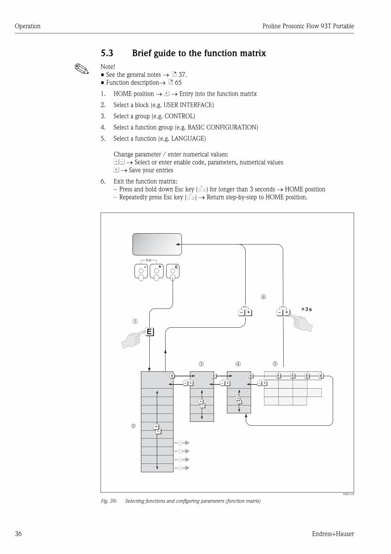
5.3 Brief guide to the function matrix
! Note!
• See the general notes → ä 37.
• Function description→ ä 65
1. HOME position → F → Entry into the function matrix
2. Select a block (e.g. USER INTERFACE)
3. Select a group (e.g. CONTROL)
4. Select a function group (e.g. BASIC CONFIGURATION)
5. Select a function (e.g. LANGUAGE)
Change parameter / enter numerical values:
OS → Select or enter enable code, parameters, numerical values
F → Save your entries
6. Exit the function matrix:
– Press and hold down Esc key (X) for longer than 3 seconds → HOME position
– Repeatedly press Esc key (X) → Return step-by-step to HOME position.
A0001210
Fig. 39: Selecting functions and configuring parameters (function matrix)
- + E
Esc
>3s
E
E
E
E
E E E E E E E
–
+
–
+ –
E
+
Esc
–
+– +– +–
+
Esc
–
m
o p q
r
n
+

Proline Prosonic Flow 93T Portable Operation
Endress+Hauser 37
5.3.1 General notes
The Quick Setup menu (→ ä 43) contains the default settings that are adequate for commissioning.
Complex measuring operations on the other hand necessitate additional functions that you can
configure as necessary and customize to suit your process parameters. The function matrix,
therefore, comprises a multiplicity of additional functions which, for the sake of clarity, are arranged
on a number of menu levels (blocks, groups, and function groups).
Comply with the following instructions when configuring functions:
• You select functions as described on → ä 36. Each cell in the function matrix is identified by a
numerical or letter code on the display.
• You can switch off certain functions (OFF). If you do so, related functions in other function groups
will no longer be displayed.
• Certain functions prompt you to confirm your data entries.
Press OS to select "SURE [ YES ]" and press F to confirm. This saves your setting or starts a
function, as applicable.
• Return to the HOME position is automatic if no key is pressed for 5 minutes.
! Note!
• The transmitter continues to measure while data entry is in progress, i.e. the current measured
values are output via the signal outputs in the normal way.
• If the power supply fails all preset and parameterized values remain safely stored in the EEPROM.
" Caution!
All functions are described in detail, as is the function matrix itself on → ä 65.
5.3.2 Enabling the programming mode
The function matrix can be disabled. Disabling the function matrix rules out the possibility of
inadvertent changes to device functions, numerical values or factory settings. A numerical code
(factory setting = 80) has to be entered before settings can be changed.
If you use a code number of your choice, you exclude the possibility of unauthorized persons
accessing data.
Comply with the following instructions when entering codes:
• If programming is disabled and the OS operating elements are pressed in any function, a prompt
for the code automatically appears on the display.
• If "0" is entered as the private code, programming is always enabled.
• The Endress+Hauser service organization can be of assistance if you mislay your personal code.
" Caution!
Changing certain parameters such as all sensor characteristics, for example, influences numerous
functions of the entire measuring system, particularly measuring accuracy.
There is no need to change these parameters under normal circumstances and consequently, they
are protected by a special code known only to the Endress+Hauser service organization. Please
contact Endress+Hauser if you have any questions.
5.3.3 Disabling the programming mode
Programming mode is disabled if you do not press an operating element within 60 seconds following
automatic return to the HOME position.
You can also disable programming in the "ACCESS CODE" function by entering any number other
than the customer's code.

Operation Proline Prosonic Flow 93T Portable
38 Endress+Hauser
5.4 Error messages
5.4.1 Type of error
Errors that occur during commissioning or measuring are displayed immediately. If two or more
system or process errors occur, the error with the highest priority is the only one shown on the
display.
The measuring system distinguishes between two types of error:
• System error: this group includes all device errors, for example communication errors, hardware
errors, etc. (→ ä 52).
• Process error: this group includes all application errors, e.g. measuring range exceeded
(→ ä 54).
A0001211
Fig. 40: Error messages on the display (example)
1 Error type: P = process error, S = system error
2 Error message type: $ = fault message, ! = notice message, (definition: → ä 52)
3 Error designation: e.g. S. V. RANGE CH1. = sound velocity of channel 1 is outside the measuring range
4 Error number: e.g. #492
5 Duration of most recent error occurrence (in hours, minutes and seconds)
5.4.2 Error message types
Users have the option of weighting system and process errors differently, by defining them as either
Fault messages or Notice messages. This is specified by means of the functions in the function
matrix. → ä 65. Serious system errors, e.g. module defects, are always identified and classed as
"fault messages" by the measuring device.
Notice message (!)
• Displayed as → Exclamation mark (!), error group (S: system error, P: process error).
• The error in question has no effect on the outputs of the measuring device.
Fault message ( $)• Displayed as → Lightning flash ($), error designation (S: system error, P: process error)
• The error in question has a direct effect on the outputs.
The response of the outputs (failsafe mode) can be defined by means of functions in the function
matrix (→ ä 56).
! Note!
• Error conditions can be output via the relay outputs.
• If an error message occurs, an upper or lower signal level for the breakdown information
according to NAMUR NE 43 can be output via the current output.
1
2 4 5 3
+24.502XXXXXXXXXX#000 00:00:05
P
+24.502

Proline Prosonic Flow 93T Portable Operation
Endress+Hauser 39
5.4.3 Confirming error messages
For plant and process safety reasons, the measuring device can be configured in such a way that
fault messages displayed ($) not only have to be eliminated but also have to be confirmed by pressing
F. Only then will error messages disappear from the display!
This function is enabled or disabled via the ACKNOWL. FAULTS function.
! Note!
• Fault messages ($) can also be reset and confirmed via the status input.
• Notice messages (!) do not have to be confirmed. However, they remain on the display until the
cause for the error has been eliminated.
5.5 Communication
5.5.1 FieldCare
FieldCare is Endress+Hauser’s FDT-based plant asset management tool and allows the configuration
and diagnosis of intelligent field devices. By using status information, you also have a simple but
effective tool for monitoring devices. The Proline flowmeters are accessed via a service interface or
via the service interface FXA193.
Commissioning Proline Prosonic Flow 93T Portable
40 Endress+Hauser
6 Commissioning
6.1 Function check
Make sure that all final checks have been completed before you commission your measuring point:
• Checklist for "Post-installation check" → ä 30
• Checklist for "Post-connection check" → ä 32
6.2 Switching on the measuring device
# Warning!
The measuring device only complies with the general safety requirements in accordance with
EN 61010-1 and the EMC requirements of IEC/EN 61326 during storage battery operation.
Disconnect the charger from the measuring device for measuring operation.
The measuring device is switched on by pressing the ON/OFF switch ≥ 3 seconds (→ ä 31,
→ å 36, No. 1).
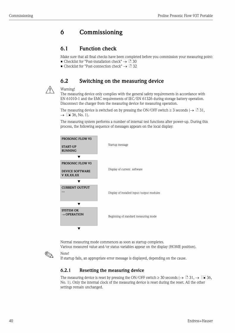
The measuring system performs a number of internal test functions after power-up. During this
process, the following sequence of messages appears on the local display:
Normal measuring mode commences as soon as startup completes.
Various measured value and/or status variables appear on the display (HOME position).
! Note!
If startup fails, an appropriate error message is displayed, depending on the cause.
6.2.1 Resetting the measuring device
The measuring device is reset by pressing the ON/OFF switch ≥ 30 seconds (→ ä 31, → å 36,
No. 1). Only the internal clock of the measuring device is reset during the reset. All the other
settings remain unchanged.
PROSONIC FLOW 93
START-UP
RUNNING
Startup message
Æ
PROSONIC FLOW 93
DEVICE SOFTWARE
V XX.XX.XX
Display of current software
Æ
CURRENT OUTPUT…
Display of installed input/output modules
Æ
SYSTEM OK
→ OPERATIONBeginning of standard measuring mode
Æ

Proline Prosonic Flow 93T Portable Commissioning
Endress+Hauser 41
6.3 Commissioning via onsite display
6.3.1 Quick Setup "Sensor Installation"
The installation distances needed to install the sensors can be determined using the Quick Setup
menu → ä 13.
A0011560-en
Fig. 41: Quick Setup menu "Sensor" (only via onsite display)
++ +E EEsc
E+-
XXX.XXX.XX
HOME-POSITION
m
n p q ro
s
t
Quick Setup
Selecting Another Measurement? NoYes
B
QSSensor Units
1001
2000
Setup
Language
Sensor
6880
Measurement
Clamp On InsertionSound Velocity
Liquid
Sound VelocityPipe Wall Thickness Off
No
No
No
Yes
Yes
Yes
SensorType
SensorType
SensorType
SensorType
SensorType
Pipe Standard Pipe Standard Pipe Standard
Pipe Material
Pipe Material
Pipe Material
Pipe Diameter Pipe Diameter
Pipe Diameter
Liquid
SoundVelocity Liquid
Arc Length
PositionSensor
6881 688168816881
6520 65206520
6522
6522
6522
6526 6526
6526
6540
6542
6542
6542
6887
6882 6882 6882
6521 65216521
6524
6524
6527
6527
6524
6524
6524
6527
6525 6525
6525
6541
6884
6885
6886
6888
6886
Sensor-Configuration
Sensor-Configuration
Sensor-Configuration
NominalDiameter
NominalDiameter
NominalDiameter
SoundVelocity Pipe
SoundVelocity Pipe
SoundVelocity Liquid
SoundVelocity Pipe
SoundVelocity Pipe
SoundVelocity Pipe
Store?
Store?
Store?Wall Thickness
Wall Thickness
Wall Thickness Wall Thickness
Wall Thickness
Circumference Circumference
Circumference
Temperature
Wire Length
SensorDistance
SensorDistance
Path Length
SelectionMeasurement
ReferenceValue
6881
6523
6527
6527
SoundVelocity Liquid

Commissioning Proline Prosonic Flow 93T Portable
42 Endress+Hauser
! Note!
• The installation distances can also be determined via the Applicator online tool → ä 15.
• The display returns to the function SETUP SENSOR (1001) if you press the ESC key combination
during parameter interrogation.
m Selection of the system units only influences the functions:
• UNIT TEMPERATURE (0422)
• UNIT LENGTH (0424)
• UNIT VELOCITY (0425)
➁ The necessary installation distances are determined with the CLAMP ON option.
➂ The INSERTION option is not supported by the Prosonic Flow 93T sensor.
➃ The SOUND VELOCITY LIQUID option is only needed for the DDU18 sensor.
"Save?" prompt:
• YES = The value measured during Quick Setup is accepted in the appropriate function.
• NO = The measurement is discarded and the original value remains.
➄ The SOUND VELOCITY PIPE option is only needed for the DDU18 sensor.
"Save?" prompt:
• YES = The value measured during Quick Setup is accepted in the appropriate function.
• NO = The measurement is discarded and the original value remains.
➅ The WALL THICKNESS option is only needed for the DDU20 sensor.
"Save?" prompt:
• YES = The value measured during Quick Setup is accepted in the appropriate function.
• NO = The measurement is discarded and the original value remains.
➆ The POSITION SENSOR function (6884) only appears if:
• The CLAMP ON option is selected in the MEASUREMENT function (6880)
and
• Two traverses are selected in the SENSOR CONFIGURATION function (6882)
➇ The WIRE LENGTH function (6885) only appears if:
• The CLAMP ON option is selected in the MEASUREMENT function (6880)
and
• One traverse is selected in the SENSOR CONFIGURATION function (6882)
Proline Prosonic Flow 93T Portable Commissioning
Endress+Hauser 43
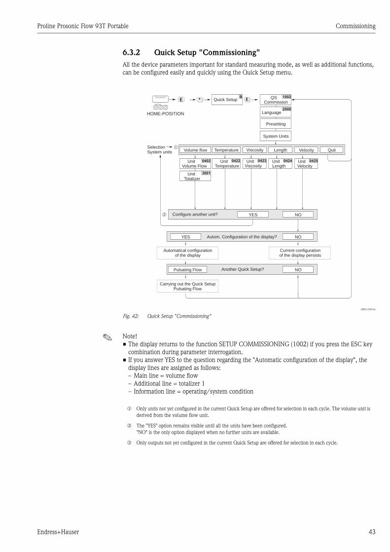
6.3.2 Quick Setup "Commissioning"
All the device parameters important for standard measuring mode, as well as additional functions,
can be configured easily and quickly using the Quick Setup menu.
A0011559-en
Fig. 42: Quick Setup "Commissioning"
! Note!
• The display returns to the function SETUP COMMISSIONING (1002) if you press the ESC key
combination during parameter interrogation.
• If you answer YES to the question regarding the "Automatic configuration of the display", the
display lines are assigned as follows:
– Main line = volume flow
– Additional line = totalizer 1
– Information line = operating/system condition
++ +E
m
n
EEsc
E+-
XXX.XXX.XX
HOME-POSITION
Commission
Language
System Units
Presetting
Quick Setup QS 1002
2000
Volume flow Temperature Viscosity Length Velocity Quit
Configure another unit? NOYES
Unit Unit Unit Unit Unit
Unit
Volume Flow Temperature Viscosity Length Velocity
Totalizer
SelectionSystem units
0402 0422 0423 0424 0425
3001
B
Autom. Configuration of the display? NO
NO
YES
Pulsating Flow
Carrying out the Quick SetupPulsating Flow
Automatical configurationof the display
Another Quick Setup?
Current configurationof the display persists
m Only units not yet configured in the current Quick Setup are offered for selection in each cycle. The volume unit is
derived from the volume flow unit.
n The "YES" option remains visible until all the units have been configured.
"NO" is the only option displayed when no further units are available.
o Only outputs not yet configured in the current Quick Setup are offered for selection in each cycle.

Commissioning Proline Prosonic Flow 93T Portable
44 Endress+Hauser
6.3.3 Quick Setup "Pulsating Flow"
A flow that fluctuates severely, for a temporary period, occurs when using pump types that transport
media in a pulsating manner, such as reciprocating pumps, peristaltic pumps and eccentric pumps.
Negative flow on account of the closing volume or valve leakage can also occur with these pumps.
! Note!
Execute the Quick Setup "Commissioning" before running the Quick Setup "Pulsating Flow"
→ ä 43.
A0001213
Fig. 43: Flow characteristic of different pump types
A With high pulsating flow
B With low pulsating flow
1 1-cylinder eccentric pump
2 2-cylinder eccentric pump
3 Solenoid pump
4 Peristaltic pump, flexible connecting cable
5 Multi-cylinder reciprocating pump
High pulsating flows
By specifically configuring a number of different device functions via the "Pulsating Flow" Quick
Setup, flow fluctuations over the entire flow range can be compensated for, and pulsating liquid
flows can be measured correctly. The process for executing the Quick Setup menu is described in
detail in the next section.
! Note!
It is recommended to always run the "Pulsating Flow" Quick Setup if you are unsure of the exact
flow characteristics.
Low pulsating flows
It is not absolutely essential to run the Quick Setup if only minor flow fluctuations occur, e.g. when
using gear-type pumps, three-cylinder or multi-cylinder pumps.
In such situations, however, it is advisable to adapt the functions listed below to meet the local
process conditions to achieve a stable, constant output signal. This applies, in particular, to the
current output:
• Measuring system damping: "SYSTEM DAMPING" function → Increase value
• Current output damping: "TIME CONSTANT" function → Increase value
Q
Q
Q Q
Q
t
t
t t
t
1
3
2 5
4
A B

Proline Prosonic Flow 93T Portable Commissioning
Endress+Hauser 45
Running the "Pulsating Flow" Quick Setup
With the aid of this Quick Setup, the user is systematically guided through all the device functions
that have to be adjusted and configured for measuring operation with pulsating flow. Values that
are already configured, such as the measuring range, current range or full scale value, are not
changed in the process!
A0011561-en
Fig. 44: "Quick Setup" menu for operation with high pulsating flow
! Note!
• The display returns to the function SETUP PULSATING FLOW (1003) if you press the ESC key
combination during parameter interrogation.
• This Quick Setup can either be called up directly after the "COMMISSIONING" Quick Setup, or
it can be called up manually via the SETUP PULSATING FLOW function (1003).
+ EB
m
n
1003
2002
3002 3002 3002
8005
6400
6402
6403
6403
EEsc
E+-
XXX.XXX.XX
HOME-POSITION
Quick Setup
YES NO
QuitSelectionTotalizer Totalizer 3 Totalizer 2 Totalizer 1
AlarmDelay
Assign
On-value
Off-value
Pressure
LF-Cutoff
LF-Cutoff
LF-Cutoff
pulse suppr.
Quit Quick Setup
Puls. Flow
DisplayDamping
TotalizerMode (DAC)
TotalizerMode (DAB)
TotalizerMode (DAA)
Select anotherChannel?
YES NO
QS
Configure anotherTotalizer?
m Only counters not yet configured in the current Quick Setup are offered for selection in each cycle.
n The "YES" option remains visible until all the counters have been configured.
"NO" is the only option displayed when no further counters are available.
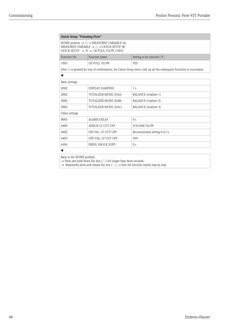
Commissioning Proline Prosonic Flow 93T Portable
46 Endress+Hauser
Quick Setup "Pulsating Flow"
HOME position → F → MEASURED VARIABLE (A)
MEASURED VARIABLE → O → QUICK SETUP (B)
QUICK SETUP → N → QS PULS. FLOW (1003)
Function No. Function name Setting to be selected ( P )
1003 QS PULS. FLOW. YES
After F is pressed by way of confirmation, the Quick Setup menu calls up all the subsequent functions in succession.
Æ
Basic settings
2002 DISPLAY DAMPING 1 s
3002 TOTALIZER MODE (DAA) BALANCE (totalizer 1)
3002 TOTALIZER MODE (DAB) BALANCE (totalizer 2)
3002 TOTALIZER MODE (DAC) BALANCE (totalizer 3)
Other settings
8005 ALARM DELAY 0 s
6400 ASSIGN LF CUT OFF VOLUME FLOW
6402 ON-VAL. LF CUT OFF Recommended setting 0.4 l/s
6403 OFF-VAL. LF CUT OFF 50%
6404 PRESS. SHOCK SUPP. 0 s
Æ
Back to the HOME position
→ Press and hold down Esc key (X) for longer than three seconds.
→ Repeatedly press and release Esc key (X) → Exit the function matrix step by step

Proline Prosonic Flow 93T Portable Commissioning
Endress+Hauser 47
6.4 Application-specific commissioning
6.4.1 Zero point adjustment
Zero point adjustment is generally not necessary!
Experience shows that the zero point adjustment is advisable only in special cases:
• To achieve highest measuring accuracy with very low flow rates.
• Under extreme process or operating conditions (e.g. very high process temperatures or very high
viscosity fluids).
Preconditions for a zero point adjustment
Note the following before you perform a zero point adjustment:
• A zero point adjustment can be performed only with fluids that have no gas or solid contents.
• Zero point adjustment is performed with the measuring tube completely filled and at zero flow
(v=0 m/s). This can be achieved, for example, with shutoff valves upstream and/or downstream
of the measuring range or by using existing valves and gates (→ ä 47).
– Standard operation → Valves 1 and 2 open
– Zero point adjustment with pump pressure → Valve 1 open / valve 2 closed
– Zero point adjustment without pump pressure → Valve 1 closed / valve 2 open
" Caution!
• If the fluid is very difficult to measure (e.g. containing entrained solids or gas) it may prove
impossible to obtain a stable zero point despite repeated zero point adjustments. In instances of
this nature, please contact your Endress+Hauser service center.
• You can view the currently valid zero point value using the ZERO POINT function.
A0011585
Fig. 45: Zero point adjustment and shutoff valves
1
2

Commissioning Proline Prosonic Flow 93T Portable
48 Endress+Hauser
Performing a zero point adjustment
1. Operate the system until normal operating conditions resume.
2. Stop the flow (v = 0 m/s).
3. Check the shutoff valves for leaks.
4. Check that operating pressure is correct.
5. Using the local display, select the "ZEROPOINT ADJUST" function in the function matrix:
HOME → F → R → BASIC FUNCTIONS
BASIC FUNCTIONS → F → R → PROCESS PARAMETER CH1/CH2
PROCESS PARAMETER → F → R → ADJUSTMENT
ADJUSTMENT → F → ZEROPOINT ADJUST
6. When you press OS you are automatically prompted to enter the access code if the function
matrix is still disabled. Enter the code.
7. With OS, select the START setting and confirm with F .
Acknowledge the security prompt with YES and press F to confirm. Zero point adjustment is
now started:
– The message "ZEROPOINT ADJUST RUNNING" appears on the display for 30 to 60 seconds
while adjustment is in progress.
– If the flow in the pipe exceeds 0.1 m/s, the following error message appears on the display:
ZERO ADJUST NOT POSSIBLE.
– When the zero point adjustment completes, the "ZERO ADJUST" function reappears on the
display.
8. Back to the HOME position
– Press and hold down Esc key (X) for longer than three seconds.
– Repeatedly press and release the Esc key (X).
6.5 Using the data logger
Prosonic Flow has the capability to log volume flow, flow velocity, sound velocity, signal strength,
signal to noise ratio, the content of the three internal totalizers, external volume flow, and the actual
current of the current input. The data set is fixed and not configurable. The sampling time is
configurable. The logged data are stored on an external memory unit (1 GB USB memory stick) in
a CSV text format.
Logging is started from the LOGGING function found in the OUTPUTS → DATALOGGER menu
when a memory stick is available. Logging is stopped in the same function or by removing the
memory stick from the unit. The latter is not a recommended method due to the remote possibility
corrupting the data.
6.6 Data exchange with Prosonic Flow 93T
Prosonic Flow 93T uses a text file format commonly referred to as a CSV format (Comma Separated
Values) for its data exchange.
A logged data record is placed on one line. A record contains a number of fields (time stamp,
measurement parameters, flow data, etc.). A delimiter – a blank space, semi-colon, comma or other
character that indicates the beginning or end of a field – is used to organize the fields into columns.
A separator – usually a point (.) or a comma (,) – is used to identify the location of the decimal.
Prosonic Flow 93T uses the format semicolon (;) as field delimiter and point (.) as decimal separator.
Adjustments may need to be made in spreadsheet software by setting the field delimeter and
decimal separator correctly prior to importing the data from the flowmeter to ensure proper
visualization of the data. The adjustments required are dependant on the local settings used by the
PCs and Laptops in a particular region. In general, set the field delimiter to semi-colon (;) and the
decimal separator to point (.) and the logged data will be converted to a format that is compatible
with the numeric settings of the local PC or Laptop.
Proline Prosonic Flow 93T Portable Maintenance
Endress+Hauser 49
7 Maintenance
7.1 General
The flow measuring system Prosonic Flow 93T requires no special maintenance.
Exterior cleaning
When cleaning the exterior of measuring devices, always use cleaning agents that do not attack the
surface of the housing and the seals.
Coupling fluid
A coupling fluid is required to ensure the acoustic link between the sensor and the piping. This is
applied to the sensor surface during commissioning. Periodic replacement of the coupling fluid is
usually not required.
7.2 Charging the device
Prosonic Flow 93T is charged applying the supplied power supply type FW7362M12 or the optional
DK9ZT-2 automobile cigarette lighter charging cable. Prosonic Flow 93T is supplied pre-charged,
but it is recommended to charge the device before first use.
The Prosonic Flow 93T can be charged in the temperature range +5 to +45 °C (+41 to +113 °F).
The charging process is monitored and protected. It will idle when the temperature at the battery
pack exceeds +35 °C (+95 °F) and resume when the temperature drops below that temperature.
Below +5 °C (+41 °F) and above +45 °C (+113 °F) charging is terminated. The charging time is
4 hours when starting empty. Good maintenance praxis is to charge the battery pack fully before
use and optimally to discharge it fully before recharging to ensure optimal battery life.
The device will automatically stop the charging when the battery is fully charged. The charge bar
will indicate 100%.

Accessories Proline Prosonic Flow 93T Portable
50 Endress+Hauser
8 Accessories
Various accessories, which can be ordered separately from Endress+Hauser, are available for the
transmitter and the sensor. The Endress+Hauser service organization can provide detailed
information on the order codes on request.
Device-specific accessories
Measuring principle-specific accessories
Accessory Description Order code
Sensor P
(DN 15 to 65 / ½ to 2½")
Clamp-on version
DN 15 to 65 (½ to 2½")
• –40 to +100 °C (–40 to +212 °F)
• –40 to +150 °C (–40 to +302 °F)
DK9PT - 1A
DK9PT - 2A
Sensor P
(DN 50 to 4000 / 2 to 160")
Clamp-on version
DN 50 to 300 (2 to 12")
• –40 to +80 °C (–40 to +176 °F)
• –40 to +170 °C (–40 to +338 °F)
DK9PT - BA
DK9PT - FA
DN 100 to 4000 (4 to 160")
• –40 to +80 °C (–40 to +176 °F)
• 0 to +170 °C (+32 to +338 °F)
DK9PT - AA
DK9PT - EA
Sensor DDU18 Sensor for sound velocity measurement
–40 to +80 °C (–40 to +176 °F)
0 to +170 °C (+32 to +338 °F)
50091703
50091704
Sensor DDU20 Sensor for wall thickness measurement.
• –20 to +60 °C (–4 to +140 °F) 71112217
Accessory Description Order code
Sensor holder set • Prosonic Flow P (DN 15 to 65 / ½ to 2½"):
Sensor holder, clamp-on version DK9SH - 2
• Prosonic Flow P (DN 50 to 4000 / 2 to 160")
– Sensor holder, fixed retaining nut, clamp-on version
– Sensor holder, removable retaining nut, clamp-on version
DK9SH - A
DK9SH - B
Clamp-on installation set
Clamp On
• DN < 1500 (60") (textile strapping)
• DN ≥ 1500 (60") (textile strapping)
• DN 50 to 300 (2 to 12"): 0 to +170 °C (+32 to +338 °F)
(stainless steel strapping)
DK9ZT - D
DK9ZT - E
DK9ZT - B
Connecting cable 5 m (16.4 ft) sensor cable, PTFE, –40 to +170 °C (–40 to +338 °F)
10 m (32.8 ft) sensor cable, PTFE, –40 to +170 °C (–40 to +338 °F)
DK9SS - CEE
DK9SS - CEF
Acoustic coupling fluid • Coupling fluid: 0 to +170 °C (+32 to +338 °F), standard,
high temperature
• Adhesive coupling fluid: –40 to +80 °C (–40 to +176 °F)
• Water-soluble coupling fluid: –20 to +80 °C (–4 to +176 °F)
• Coupling fluid DDU20: –20 to +60 °C (–4 to +140 °F)
• Coupling fluid: –40 to +80 °C (–40 to +176 °F), standard,
type MBG2000
DK9CM - 2
DK9CM - 3
DK9CM - 4
DK9CM - 6
DK9CM - 7

Proline Prosonic Flow 93T Portable Accessories
Endress+Hauser 51
Service-specific accessories
Accessory Description Order code
Applicator Software for selecting and planning flowmeters.
The Applicator can be downloaded from the Internet or ordered on
CD-ROM for installation on a local PC.
Contact your Endress+Hauser representative for more information.
DXA80 - *
Fieldcheck Tester/simulator for testing flowmeters in the field.
When used in conjunction with the "FieldCare" software package,
test results can be imported into a database, printed out and used for
official certification.
Contact your Endress+Hauser representative for more information.
50098801
FieldCare FieldCare is Endress+Hauser's FDT-based plant asset management
tool. It can configure all intelligent field units in your system and
helps you manage them.
By using the status information, it is also a simple but effective way
of checking their status and condition.
See the product
page on the
Endress+Hauser
website:
www.endress.com
FXA193 Service interface from the measuring device to the PC for operation
via FieldCare.
FXA193 – *
Communication cable Communication cable for connecting the Prosonic Flow 93T
transmitter to the FXA193 service interface.
DK9ZT – A
FXA291 Service interface from the measuring device to the PC for operation
via FieldCare.
FXA291 – *
Communication cable Communication cable for connecting the Prosonic Flow 93T
transmitter to the FXA291 service interface.
DK9ZT – 8

Troubleshooting Proline Prosonic Flow 93T Portable
52 Endress+Hauser
9 Troubleshooting
9.1 Troubleshooting instructions
Always start troubleshooting with the following checklist if faults occur after commissioning or
during operation. The routine takes you directly to the cause of the problem and the appropriate
remedial measures.
9.2 System error messages
Serious system errors are always recognized by the instrument as "Fault message" and are shown
as a lightning flash ($) on the display! Fault messages immediately affect the inputs and outputs.
" Caution!
In the event of a serious fault, a flowmeter might have to be returned to the manufacturer for repair.
Important procedures must be carried out before you return a flowmeter to Endress+Hauser
→ ä 6. Always enclose a duly completed "Declaration of Contamination" form. A copy of the form
can be found at the end of these Operating Instructions!
! Note!
See the information or troubleshooting guide on → ä 52.
Check the display
Nothing shown on the
display.
Check the device storage battery and charge it if necessary.
Display texts are in a
foreign language.
1. Switch off the measuring device.
2. Press and hold down both the OS keys and switch on the measuring device.
The display text will appear in English (default) and is displayed at maximum contrast.
Æ
Error messages on display
Errors that occur during commissioning or measuring are displayed immediately. Error messages consist of a variety of
icons. The meanings of these icons are as follows:
– Type of error: S = System error, P = Process error
– Error message type: $ = Fault message, ! = Notice message
– S.V. RANGE CH1 = error designation (e.g. sound velocity for channel 1 is outside the measuring range)
– 03:00:05 = duration of error occurrence (in hours, minutes and seconds)
– #492 = error number
" Caution!
• See the information on → ä 38!
• The measuring system interprets simulations and positive zero return as system errors, but displays them as notice
messages only.
Error number:
No. 001 – 399
No. 501 – 799
System error (device error) has occurred → ä 52
Error number:
No. 401 – 499
Process error (application error) has occurred → ä 54
Æ
Other error (without error message)
Some other error has
occurred.
Diagnosis and rectification → ä 55

Proline Prosonic Flow 93T Portable Troubleshooting
Endress+Hauser 53
No. Error message/type Cause Remedy (spare parts → ä 50 ff.)
S = System error
$ = Fault message (with an effect on the outputs)
! = Notice message (without any effect on the outputs)
No. # 0xx → Hardware error
001 S: CRITICAL FAILURE
$: # 001
Critical device error. Replace the amplifier board.
011 S: AMP HW EEPROM
$: # 011
Amplifier:
Faulty EEPROM
Replace the amplifier board.
012 S: AMP SW EEPROM
$: # 012
Amplifier:
Error when accessing data of the
EEPROM.
The EEPROM data blocks in which an
error occurred are displayed in the
TROUBLESHOOTING function. The
errors in question have to be confirmed
with the Enter key; faulty parameters are
then replaced by predefined standard
values.
! Note!
The device has to be restarted if an error
occurs in the totalizer block (see also error
# 111 / CHECKSUM TOTAL.).
082 S: SENS. DOWN CH1
$: # 082
Connection between sensor channel 1
and transmitter interrupted.
• Check the cable connection between
the sensor and transmitter.
• Check whether the sensor connector is
inserted until the stop.
• The sensor might be defective.
• Incorrect sensor connected.
• The wrong sensor was selected in the
SENSOR TYPE function (No. 6881).
085 S: SENS. UP CH1
$: # 085
No. # 2xx → Error with DAT / no data reception
261 S: COMMUNIC. I/O
$: # 261
No data reception between amplifier and
I/O board or faulty internal data transfer.
Check BUS contacts
No. # 3xx → System range limits exceeded
363 S: RANGE CUR.IN
!: # 363
Current input:
The active current value is outside the set
range.
• Change the start and end values
configured.
• Check the settings of the external
sensor.
392 S: SIGNA. LOW CH1
$: # 392
Attenuation of acoustic measurement
section too high.
• Check whether the coupling fluid has
to be renewed.
• The attenuation of the fluid might be
too high.
• The attenuation of the pipe might be
too high.
• Check the sensor distance (installation
dimensions).
• Reduce the number of traverses if
possible.
No # 5xx → Application errors
501 S: SW.-UPDATE ACT.
!: # 501
New amplifier or communication module
software version being loaded. Currently
no other functions are possible.
Wait until the procedure is complete. The
device will restart automatically.
502 S: UP-/DOWNLOAD
ACT.
!: # 502
Up- or downloading the device data via
operating program. Currently no other
functions are possible.
Wait until the procedure is complete.

Troubleshooting Proline Prosonic Flow 93T Portable
54 Endress+Hauser
9.3 Process error messages
Process errors can be defined as either "Fault" or "Notice" messages and can thus be weighted
differently.
! Note!
See the information on → ä 37 ff. and → ä 55.
No. # 6xx → Simulation operation active
601 S: POS. ZERO RET.
!: # 601
Positive zero return active.
" Caution!
This notice message has the highest
display priority!
Switch off positive zero return.
661 S: SIM. CURR. INP.
!: # 661
Current input simulation active. Switch off simulation.
691 S: SIM. FAILSAFE
!: # 691
Simulation of failsafe mode (outputs)
active.
Switch off simulation.
692 S: SIM. MEASURAND
!: # 692
Simulation of a measured variable active
(e.g. mass flow).
Switch off simulation.
698 S: DEV. TEST ACT.
!: # 698
The measuring device is being checked on
site via the test and simulation device.
−
No. Error message/type Cause Remedy (spare parts → ä 50 ff.)
Type Error message / No. Cause Remedy
P = Process error
$ = Fault message (with an effect on the inputs/outputs)
! = Notice message (without any effect on the inputs/outputs)
P
$PIPE DATA? CH1
# 469
The internal diameter is negative. In the "PIPE DATA" function group, check
the values of the functions "OUTER
DIAMETER" and "WALL THICKNESS" or
"LINING THICKNESS".
P
$S. V. RANGE CH1
# 492
The sound velocity in channel 1/2 is
outside the search range of the
transmitter.
– Check the installation dimensions.
– If possible, check the sound velocity of
the liquid or check the specialist
literature.
If the current sound velocity is outside the
defined search range, the corresponding
function must be changed in the LIQUID
DATA function group.
Detailed explanations can be found under
the SOUND VELOCITY LIQUID function
(6542).
P
!
INTERF. CH1
# 495
The wave transmitted in the pipe may
superimpose the useful signal. We
recommend you alter the sensor
configuration in the event of this error
message.
" Caution!
The sensor configuration must be changed
if the measuring device indicates zero flow
or low flow.
In the SENSOR CONFIGURATION
function (6882), change the number of
traverses from 2 or 4 to 1 or 3 and mount
the sensors accordingly.

Proline Prosonic Flow 93T Portable Troubleshooting
Endress+Hauser 55
9.4 Process errors without messages
Symptoms Rectification
! Note!
You may have to change or correct certain settings of the function matrix in order to rectify faults. For an explanation of
the functions listed below, e.g. DISPLAY DAMPING, see → ä 65 ff.
Negative flow values displayed even
though the fluid is flowing forwards in
the pipe.
1. Check the wiring → ä 31.
If necessary, switch the connections for the terminals for "up" and "down".
2. Change the "INSTL. DIR. SENSOR" function accordingly.
Measured value reading fluctuates even
though flow is steady.
1. Check the fluid for presence of gas bubbles.
2. "TIME CONSTANT" function (current output) → Increase value
3. "DISPLAY DAMPING" function → Increase value
The measured value display or
measured value output is pulsating or
fluctuating, e.g. due to reciprocating
pumps, peristaltic pumps, diaphragm
pumps or pumps with similar
transporting characteristics.
Run the "Pulsating Flow" Quick Setup → ä 44.
If these measures do not rectify the problem, a pulsation damper has to be
installed between the pump and the flowmeter.
Measured value reading shown on
display, even though the fluid is at a
standstill and the measuring tube is full.
1. Check the fluid for presence of gas bubbles.
2. Activate the "LOW FLOW CUTOFF" function, i.e. enter or increase the
value for the switch point.
The fault cannot be rectified or some
other fault not described above has
occurred.
In these instances, please contact your
Endress+Hauser service organization.
The following options are available for tackling problems of this nature:
Request the services of an Endress+Hauser service technician
If you contact our service organization to have a service technician sent out,
please be ready with the following information:
– Brief description of the fault
– Nameplate specifications: order code and serial number
Return devices to Endress+Hauser
The measures listed must be carried out before you return a measuring device
requiring repair or calibration to Endress+Hauser.
Always enclose the duly completed "Declaration of Contamination" form with
the flowmeter. You will find a preprinted blank of this form at the back of this
manual.
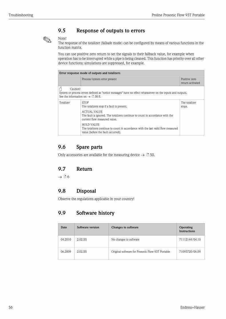
Troubleshooting Proline Prosonic Flow 93T Portable
56 Endress+Hauser
9.5 Response of outputs to errors
! Note!
The response of the totalizer (failsafe mode) can be configured by means of various functions in the
function matrix.
You can use positive zero return to set the signals to their fallback value, for example when
operation has to be interrupted while a pipe is being cleaned. This function has priority over all other
device functions; simulations are suppressed, for example.
9.6 Spare parts
Only accessories are available for the measuring device → ä 50.
9.7 Return
→ ä 6
9.8 Disposal
Observe the regulations applicable in your country!
9.9 Software history
Error response mode of outputs and totalizers
Process/system error present Positive zero
return activated
" Caution!
System or process errors defined as "notice messages" have no effect whatsoever on the inputs and outputs.
See the information on → ä 38 ff.
Totalizer STOP
The totalizers stop if a fault is present.
ACTUAL VALUE
The fault is ignored. The totalizers continue to count in accordance with the
current flow measured value.
HOLD VALUE
The totalizers continue to count in accordance with the last valid flow measured
value (before the fault occurred).
The totalizer
stops.
Date Software version Changes to software Operating
Instructions
04.2010 2.02.XX No changes to software 71112144/04.10
06.2009 2.02.XX Original software for Prosonic Flow 93T Portable 71093720/06.09

Proline Prosonic Flow 93T Portable Technical data
Endress+Hauser 57
10 Technical data
10.1 Quick technical data guide
10.1.1 Application
• Measuring the flow rate of liquids in closed piping systems.
• Applications in measuring, control and regulation technology for monitoring processes.
10.1.2 Function and system design
Measuring principle The measuring system operates on the principle of transit time difference.
Measuring system The measuring system consists of one transmitter and two sensors.
Transmitter
Prosonic Flow 93T Portable
Sensor
• Prosonic Flow P Clamp On version, Nominal diameters DN 15 to 65 (½ to 2½")
• Prosonic Flow P Clamp On version, Nominal diameters DN 50 to 4000 (2 to 160")
• Prosonic Flow DDU18 (sound velocity measurement),
Nominal diameters DN 50 to 3000 (2 to 120")
• Prosonic Flow DDU20 (wall thickness measurement),
– for wall thicknesses from 2 to 50 mm (1/12 to 2") for steel pipes
– for wall thicknesses from 4 to 15 mm (1/8 to ½") for plastic pipes
(only suitable for use with PTFE and PE pipes to a certain extent)
10.1.3 Input
Measured variable Flow velocity
(transit time difference proportional to flow velocity)
Measuring range Typically v = 0 to 15 (0 to 50 ft/s) at the specified measuring accuracy
Operable flow range Over 150 : 1
Input signal Current input
• Galvanically isolated
• Passive: 0/4 to 20 mA, Ri < 150 Ω , max. 30 V DC
• Terminal voltage: min. 2 V DC to max. 30 V DC
• Time constant selectable (0.05 to 100 s)
• Full scale value adjustable
• Temperature coefficient: typ. 0.002 % o.r./°C (o.r. = of reading)
• Resolution: 0.82 μA

Technical data Proline Prosonic Flow 93T Portable
58 Endress+Hauser
10.1.4 Output
Output signal Data logger function
The device has a data logger function. The measured values can be stored in CSV format on an
external USB storage device (FAT 16/FAT 32). A recording cycle of between 1 and 99999 seconds
can be selected. USB storage devices with a maximum capacity greater than 2 GB should not be used.
Approx. 130 bytes are needed per recording. The standard supplied USB storage device has a maximum
capacity of 1 GB.
The following values are stored:
• Time (dd.mm.yyyy hh:mm:ss)
• Flow
• Sound velocity
• Flow velocity
• Signal strength
• Noise ratio
• Counter 1 to 3
• System status
• 0/4 to 20 mA current input (flow rate and active current value)
Each recording is marked with the tag name and device-specific information, such as the serial
number for example.
Low flow cut off Switch points for low flow cutoff are selectable.
Galvanic isolation All circuits for inputs, outputs, and power supply are galvanically isolated from each other.
10.1.5 Power supply
Measuring unit electrical
connection
→ ä 31
Connecting the connecting
cable
→ ä 31
Supply voltage Transmitter
Power unit
• 100 to 240 V AC, 47 to 63 Hz to Power Adapter (12 V DC, 2.5 A)
NiMH accumulator
• Operating time: up to 8 hours
• Charge time: approx. 3.6 hours
Sensor
Powered by the transmitter

Proline Prosonic Flow 93T Portable Technical data
Endress+Hauser 59
Connecting cable (sensor/
transmitter)
Only use the connecting cables supplied by Endress+Hauser.
Different versions of the connecting cables are available → ä 50.
• Cable material: PTFE
• Cable lengths: 5 m (16.4 feet), 10 m (32.8 feet)
! Note!
To ensure correct measuring results, route the connecting cable well clear of electrical machines
and switching elements.
Potential equalization For potential equalization, no special measures are necessary.
10.1.6 Performance characteristics
Reference operating
conditions
• Fluid temperature: +20 to +30 °C
• Ambient temperature: +22 °C ± 2 K
• Warm-up period: 30 minutes
Installation:
• Sensors and transmitter are grounded.
• The measuring sensors are correctly installed.
Maximum measured error The measured error depends on a number of factors. A distinction is made between the measured
error of the device (Prosonic Flow 93T = 0.5 % of the measured value) and an additional
installation-specific measured error (typically 1.5 % of the measured value) that is independent of
the device.
The installation-specific measured error depends on the installation conditions on site, such as the
nominal diameter, wall thickness, real pipe geometry, fluid, etc.
The sum of the two measured errors is the measured error at the measuring point.
A0011347
Fig. 46: Example of the measured error in a pipe with a nominal diameter DN > 200 (8")
a Measured error of the device (0.5 % o.r. ± 0.02 % o.f.s.)
b Measured error due to installation conditions (typically 1.5 % o.r.)
c Measured error at the measuring point: 0.5 % o.r. ± 0.02 % o.f.s. + 1.5 % o.r. = 2 % o.r. ± 0.02 % o.f.s.
0
0.5
2.0
3.5
%
m/s2 4 6 8 10 12
b
c
a

Technical data Proline Prosonic Flow 93T Portable
60 Endress+Hauser
Measured error at the measuring point
The measured error at the measuring point is made up of the measured error of the device
(0.5 % o.r.) and the measured error resulting from the installation conditions on site. Given a flow
velocity > 0.3 m/s (1 ft/s) and a Reynolds number > 10000, the following are typical error limits:
Measurement Report
If required, the device can be supplied with a factory measurement report. To certify the
performance of the device, a measurement is performed under reference conditions. Here, the
sensors are mounted on a pipe with a nominal diameter of DN 50 (2") or DN 100 (4") respectively.
The measurement report guarantees the following error limits of the device
[at a flow velocity > 0.3 m/s (1 ft/s) and a Reynolds number > 10000]:
Repeatability ±0.3 % for flow velocities > 0.3 m/s (1 ft/s)
10.1.7 Operating conditions: installation
Installation instructions Mounting location
→ ä 10
Orientation
→ ä 11
Inlet and outlet run → ä 11
Length of connecting cable
(sensor/transmitter)
The connecting cable is available in the following lengths:
• 5 m (16.4 ft)
• 10 m (32.8 ft)
Nominal diameter Device error limits +Installation-specific
error limits (typical)→
Error limits at the measuring
point (typical)
DN 15 (½") ±0.5 % o.r. ± 0.05 % o.f.s. + ±2.5 % o.r. → ±3 % o.r. ± 0.05 % o.f.s.
DN 25 to 200 (1 to 8") ±0.5 % o.r. ± 0.05 % o.f.s. + ±1.5 % o.r. → ±2 % o.r. ± 0.05 % o.f.s.
> DN 200 (8") ±0.5 % o.r. ± 0.02 % o.f.s. + ±1.5 % o.r. → ±2 % o.r. ± 0.02 % o.f.s.
o.r. = of reading
o.f.s. = of full scale value [Prosonic P: DN 15 to 65 ( ½ to 2½") = 10 m/s (33 ft/s),
DN 50 to 4000 (2 to 160") = 15 m/s (50 ft/s)]
Nominal diameter Guaranteed error limits of the device
DN 50 (2"), DN 100 (4") ±0.5 % o.r. ± 0.05 % o.f.s.
o.r. = of reading
o.f.s. = of full scale value [Prosonic P: DN 50 (2"), DN 100 (4") = 15 m/s (50 ft/s)]

Proline Prosonic Flow 93T Portable Technical data
Endress+Hauser 61
10.1.8 Operating conditions: environment
Ambient temperature range Transmitter
0 to +60 °C (+32 to +140 °F)
Prosonic Flow P sensor
DN 15 to 65 (½ to 2½")
• Standard: –40 to +100 °C (–40 to +212 °F)
• Optional: 0 to +150 °C (+32 to +302 °F)
DN 50 to 4000 (2 to 160")
• Standard: –40 to +80 °C (–40 to +176 °F)
• Optional: 0 to +170 °C (+32 to +338 °F)
DDU18 sensor (accessories: sound velocity measurement)
• Standard: –40 to +80 °C (–40 to +176 °F)
• Optional: 0 to +170 °C (+32 to +338 °F)
DDU20 sensor (accessories: wall thickness measurement)
–20 to +60 °C (–4 to +140 °F)
Connecting cable (sensor/transmitter)
–40 to +170 °C (–40 to +338 °F)
Storage temperature The storage temperature corresponds to the ambient temperature range.
Degree of protection Transmitter
IP 40
Sensor
IP 68 (NEMA 6P), connection IP 50
DDU18 sensor (accessories: sound velocity measurement)
IP 68 (NEMA 6P), connection IP 50
DDU20 sensor (accessories: wall thickness measurement)
IP 67 (NEMA 4X), connection IP 50
Shock and vibration resistance According to IEC 68-2-6
Electromagnetic compatibility
(EMC)
Electromagnetic compatibility (EMC requirements) according to IEC/EN 61326 "Emission to class A
requirements" and NAMUR Recommendation NE 21 and NE 43.

Technical data Proline Prosonic Flow 93T Portable
62 Endress+Hauser
10.1.9 Operating conditions: process
Medium temperature range Prosonic Flow P sensor
DN 15 to 65 (½ to 2½")
• Standard: –40 to +100 °C (–40 to +212 °F)
• Optional: –40 to +150 °C (–40 to +302 °F)
DN 50 to 4000 (2 to 160")
• Standard: –40 to +80 °C (–40 to +176 °F)
• Optional: 0 to +170 °C (+32 to +338 °F)
DDU18 sensor (accessories: sound velocity measurement)
• Standard: –40 to +80 °C (–40 to +176 °F)
• Optional: 0 to +170 °C (+32 to +338 °F)
DDU20 sensor (accessories: wall thickness measurement)
–10 to +60 °C (+14 to +140 °F)
Medium pressure range
(nominal pressure)
No pressure limitation, however perfect measurement requires that the static fluid pressure is higher
than vapor pressure.
Pressure loss There is no pressure loss.
10.1.10 Mechanical construction
Design / dimensions The dimensions and lengths of the sensor and transmitter are provided in the separate "Technical
Information" document on the device in question. This can be downloaded as a PDF file from
www.endress.com.
A list of the "Technical Information" documents available is provided on → ä 64.
Weight Transmitter
1.6 kg (3.53 lbs)
Sensor Prosonic Flow P
• DN 15 to 65 (½ to 2½") (incl. mounting material): 1.78 kg (3.9 lbs)
• DN 50 to 4000 (2 to 160") (incl. mounting material): 2.8 kg (6.2 lbs)
Sensor (accessories)
• Prosonic Flow DDU18 (incl. mounting material): 2.4 kg (5.3 lbs)
• Prosonic Flow DDU20 (incl. mounting material): 0.23 kg (0.5 lbs)
! Note!
Weight information without packaging material.
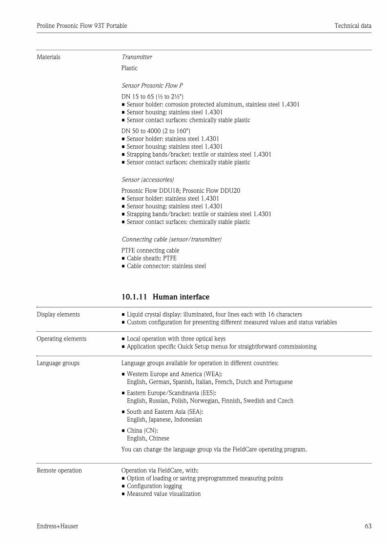
Proline Prosonic Flow 93T Portable Technical data
Endress+Hauser 63
Materials Transmitter
Plastic
Sensor Prosonic Flow P
DN 15 to 65 (½ to 2½")
• Sensor holder: corrosion protected aluminum, stainless steel 1.4301
• Sensor housing: stainless steel 1.4301
• Sensor contact surfaces: chemically stable plastic
DN 50 to 4000 (2 to 160")
• Sensor holder: stainless steel 1.4301
• Sensor housing: stainless steel 1.4301
• Strapping bands/bracket: textile or stainless steel 1.4301
• Sensor contact surfaces: chemically stable plastic
Sensor (accessories)
Prosonic Flow DDU18; Prosonic Flow DDU20
• Sensor holder: stainless steel 1.4301
• Sensor housing: stainless steel 1.4301
• Strapping bands/bracket: textile or stainless steel 1.4301
• Sensor contact surfaces: chemically stable plastic
Connecting cable (sensor/transmitter)
PTFE connecting cable
• Cable sheath: PTFE
• Cable connector: stainless steel
10.1.11 Human interface
Display elements • Liquid crystal display: illuminated, four lines each with 16 characters
• Custom configuration for presenting different measured values and status variables
Operating elements • Local operation with three optical keys
• Application specific Quick Setup menus for straightforward commissioning
Language groups Language groups available for operation in different countries:
• Western Europe and America (WEA):
English, German, Spanish, Italian, French, Dutch and Portuguese
• Eastern Europe/Scandinavia (EES):
English, Russian, Polish, Norwegian, Finnish, Swedish and Czech
• South and Eastern Asia (SEA):
English, Japanese, Indonesian
• China (CN):
English, Chinese
You can change the language group via the FieldCare operating program.
Remote operation Operation via FieldCare, with:
• Option of loading or saving preprogrammed measuring points
• Configuration logging
• Measured value visualization

Technical data Proline Prosonic Flow 93T Portable
64 Endress+Hauser
10.1.12 Certificates and approvals
CE mark The measuring system is in conformity with the statutory requirements of the EC Directives.
Endress+Hauser confirms successful testing of the device by affixing to it the CE mark.
C-Tick mark The measuring system is in conformity with the EMC requirements of the "Australian
Communications and Media Authority (ACMA)".
Other standards and
guidelines
• EN 60529
Degrees of protection provided by enclosures (IP code).
• EN 61010-1
Safety requirements for electrical equipment for measurement, control and laboratory use.
• IEC/EN 61326
"Emission in accordance with Class A requirements".
Electromagnetic compatibility (EMC requirements).
• ANSI/ISA-S82.01
Safety Standard for Electrical and Electronic Test, Measuring, Controlling and Related
Equipment - General Requirements. Pollution Degree 2, Installation Category II.
• CAN/CSA-C22.2 No. 1010.1-92
Safety Requirements for Electrical Equipment for Measurement and Control and Laboratory Use.
Pollution Degree 2.
10.1.13 Ordering information
The Endress+Hauser service organization can provide detailed ordering information and
information on the order codes on request.
10.1.14 Documentation
• Flow measurement (FA005D/06)
•Technical Information for Prosonic Flow 93T Portable (TI085D/06)

Proline Prosonic Flow 93T Portable Description of Device Functions
Endress+Hauser 65
11 Description of Device Functions
11.1 Function matrix
11.1.1 General layout of the function matrix
The function matrix consists of four levels:
Blocks -> Groups -> Function groups -> Functions
A0000961
Blocks (A, B, C, etc.)
The blocks are the highest-level grouping of the operation options for the device.
Examples of blocks available are MEASURED VARIABLES, QUICK SETUP, USER INTERFACE,
TOTALIZERS, etc.
Groups (AAA, AEA, CAA, etc.)
A block consists of one or more groups. Each group represents a more detailed selection of the
operation options in the higher-order block. Examples of groups available in the USER INTERFACE
block are CONTROL, MAIN LINE, ADDITIONAL LINE, etc.
Functions (0000, 0001, 0002, etc.)
Each function group consists of one or more functions. The functions are used to operate and
parameterize the device. Numerical values can be entered or parameters selected and saved.
Examples of functions available in the BASIC CONFIGURATION function group are LANGUAGE,
DISPLAY DAMPING, CONTRAST LCD, etc.
If the operating language of the device is to be changed, for example, proceed as follows:
1. Select the block USER INTERFACE.
2. Select the group CONTROL.
3. Select the function group BASIC CONFIGURATION.
4. Select the function LANGUAGE (here you can set the language required).
Function groups (000, 020, 060, etc.)
A group consists of one or more function groups. Each function group represents a more detailed
selection of the operation options in the higher-order group. Examples of function groups available
in the CONTROL group are BASIC CONFIGURATION, UNLOCKING/LOCKING, OPERATION,
etc.
…
…
…
…
…
…
…
…
0001
2001
0401
2021
2201
0002
2002
0402
2022
2202
0003
2003
0403
2023
2203
0009
2009
0409
2029
2209
0429
2049
2069
0421
2041
0422
2042
0423
2043
20632061 2062
0000
2000
0400
2020
2200
0420
2040
2060
000
200
040
202
220
042
204
206
AAA
BAA
ACA
CAA
CBA
D, E, …
A
B
C

Description of Device Functions Proline Prosonic Flow 93T Portable
66 Endress+Hauser
11.1.2 Codes identifying cells
Each cell (block, group, function group and function) in the function matrix has an individual,
unique code.
Blocks:
The code is a letter (A, B, C, etc.).
Groups:
The code consists of three letters (AAA, ABA, BAA, etc.).
The first letter matches the block code (i.e. each group in block A has a code starting with an A_ _;
the codes of the groups in block B start with a B _ _, and so on). The other two letters are for
identifying the group within the respective block.
Function groups:
The code consists of three digits (000, 001, 100, etc.).
Functions:
The code consists of four digits (0000, 0001, 0201, etc.).
The first three digits are the same as the code for the function group.
The last digit in the code is a counter for the functions in the function group, incrementing from 0
to 9 (e.g. function 0005 is the sixth function in group 000).
A0001251
Block Group Function group Functions
2000 2001 2002200CAAC

Proline Prosonic Flow 93T Portable Description of Device Functions
Endress+Hauser 67
11.2 Function matrix of Prosonic Flow 93T Portable
Blocks → Groups → Function groups Functions
MEASURED
VARIABLES
A → MEASURING VALUES AAA → MAIN VALUES CH1 000 → ä 68
SYSTEM UNITS ACA → CONFIGURATION 040 → ä 69
ADDITIONAL
CONFIGURATION
042 → ä 70
SPECIAL UNITS AEA → ARBITRARY UNIT 060 → ä 71
QUICK SETUP B → → → ä 71
USER INTERFACE C → CONTROL CAA → BASIC CONFIGURATION 200 → ä 72
UNLOCKING/LOCKING 202 → ä 73
OPERATION 204 → ä 74
MAIN LINE CCA → CONFIGURATION 220 → ä 75
MULTIPLEX 222 → ä 76
ADDITIONAL LINE CEA → CONFIGURATION 240 → ä 77
MULTIPLEX 242 → ä 76
INFORMATION LINE CGA → CONFIGURATION 260 → ä 81
MULTIPLEX 262 → ä 83
TOTALIZER D → TOTALIZER 1
TOTALIZER 2
TOTALIZER 3
DAA
DAB
DAC
→ CONFIGURATION 300 → ä 85
OPERATION 304 → ä 86
HANDLING TOTALIZER DJA → → ä 86
OUTPUTS E → DATA LOGGER ELA → CONFIGURATION 490 → ä 87
INFORMATION 498 → ä 87
INPUTS F → CURRENT INPUT FCA → CONFIGURATION 520 → ä 88
OPERATION 524 → ä 89
BASIC FUNCTIONS G → PROCESS PARAMETER
CH1
GIA → CONFIGURATION 640 → ä 90
ADJUSTMENT 648 → ä 92
PIPE DATA 652 → ä 92
LIQUID DATA 654 → ä 95
SYSTEM PARAMETER
CH1
GLA → CONFIGURATION 660 → ä 98
SENSOR DATA CH1 GNA → SENSOR PARAM. 688 → ä 99
CALIBRATION DATA 689 → ä 101
SUPERVISION J → SYSTEM JAA → CONFIGURATION 800 → ä 102
OPERATION 804 → ä 103
VERSION INFO JCA → DEVICE 810 → ä 104
SENSOR 820 → ä 104
AMPLIFIER 822 → ä 105
I/O MODULE 830 → ä 105
I/O SUBMODULE 1 832 → ä 105
I/O SUBMODULE 3 834 → ä 105
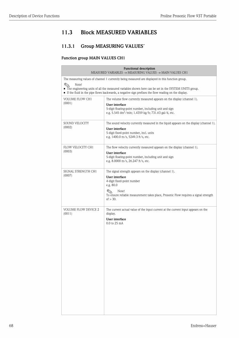
Description of Device Functions Proline Prosonic Flow 93T Portable
68 Endress+Hauser
11.3 Block MEASURED VARIABLES
11.3.1 Group MEASURING VALUES´
Function group MAIN VALUES CH1
Functional description
MEASURED VARIABLES → MEASURING VALUES → MAIN VALUES CH1
The measuring values of channel 1 currently being measured are displayed in this function group.
! Note!
• The engineering units of all the measured variables shown here can be set in the SYSTEM UNITS group.
• If the fluid in the pipe flows backwards, a negative sign prefixes the flow reading on the display.
VOLUME FLOW CH1
(0001)
The volume flow currently measured appears on the display (channel 1).
User interface
5-digit floating-point number, including unit and sign
e.g. 5.545 dm3/min; 1.4359 kg/h; 731.63 gal/d, etc.
SOUND VELOCITY
(0002)
The sound velocity currently measured in the liquid appears on the display (channel 1).
User interface
5-digit fixed-point number, incl. units
e.g. 1400.0 m/s, 5249.3 ft/s, etc.
FLOW VELOCITY CH1
(0003)
The flow velocity currently measured appears on the display (channel 1).
User interface
5-digit floating-point number, including unit and sign
e.g. 8.0000 m/s, 26.247 ft/s, etc.
SIGNAL STRENGTH CH1
(0007)
The signal strength appears on the display (channel 1).
User interface
4-digit fixed-point number
e.g. 80.0
! Note!
To ensure reliable measurement takes place, Prosonic Flow requires a signal strength
of > 30.
VOLUME FLOW DEVICE 2
(0011)
The current actual value of the input current at the current input appears on the
display.
User interface
0.0 to 25 mA

Proline Prosonic Flow 93T Portable Description of Device Functions
Endress+Hauser 69
11.3.2 Group SYSTEM UNITS
Function group CONFIGURATION
Functional description
MEASURED VARIABLES → SYSTEM UNITS → CONFIGURATION
UNIT VOLUME FLOW
(0042)
Use this function to select the unit for displaying the volume flow.
The unit you select here is also valid for low flow cut off.
Options
Metric:
Cubic centimeter → cm3/s; cm3/min; cm3/h; cm3/day
Cubic decimeter → dm3/s; dm3/min; dm3/h; dm3/day
Cubic meter → m3/s; m3/min; m3/h; m3/day
Milliliter → ml/s; ml/min; ml/h; ml/day
Liter→ l/s; l/min; l/h; l/day
Hectoliter → hl/s; hl/min; hl/h; hl/day
Megaliter →Ml/s; Ml/min; Ml/h; Ml/day
US:
Cubic centimeter → cc/s; cc/min; cc/h; cc/day
Acre foot → af/s; af/min; af/h; af/day
Cubic foot → ft3/s; ft3/min; ft3/h; ft3/day
Fluid ounce → oz f/s; oz f/min; oz f/h; oz f/day
Gallon → gal/s; gal/min; gal/h; gal/day, US kgal/s; US kgal/min; US kgal/h;
US kgal/day
Million gallon → Mgal/s; Mgal/min; Mgal/h; Mgal/day
Barrel (normal fluids: 31.5 gal/bbl) → bbl/s; bbl/min; bbl/h; bbl/day
Barrel (beer: 31.0 gal/bbl) → bbl/s; bbl/min; bbl/h; bbl/day
Barrel (petrochemicals: 42.0 gal/bbl) → bbl/s; bbl/min; bbl/h; bbl/day
Barrel (filling tanks: 55.0 gal/bbl) → bbl/s; bbl/min; bbl/h; bbl/day
Imperial:
Gallon → gal/s; gal/min; gal/h; gal/day
Million gallon/Mega gallon → Mgal/s; Mgal/min; Mgal/h; Mgal/day
Barrel (beer: 31.0 gal/bbl) → bbl/s; bbl/min; bbl/h; bbl/day
Barrel (petrochemicals: 34.97 gal/bbl → bbl/s; bbl/min; bbl/h; bbl/day
Barrel (filling tanks: 55.0 gal/bbl) → bbl/s; bbl/min; bbl/h; bbl/day
Arbitrary unit (from ARB. UNIT function group → ä 71):
_ _ _ _ → _ _ _ _/s; _ _ _ _/min; _ _ _ _/h; _ _ _ _/day
Factory setting
l/s
UNIT VOLUME
(0403)
Use this function to select the unit for displaying the volume.
Options
Metric:
cm3; dm3; m3; ml; l; hl; Ml MEGA
US:
cc; af; ft3; oz f; gal; kgal; Mgal; bbl (NORMAL FLUIDS); bbl (BEER);
bbl (PETROCHEMICALS), bbl (FILLING TANKS)
Imperial:
gal; Mgal; bbl (BEER); bbl (PETROCHEMICALS)
Arbitrary unit (from ARBITRARY UNIT function group → ä 71):
_ _ _ _
Factory setting
Liter
! Note!
The unit of the totalizers is independent of your choice here. The unit for each totalizer
is selected separately for the totalizer in question.

Description of Device Functions Proline Prosonic Flow 93T Portable
70 Endress+Hauser
Function group ADDITIONAL CONFIGURATION
Functional description
MEASURED VARIABLES → SYSTEM UNITS → ADDITIONAL CONFIGURATION
UNIT TEMPERATURE
(0422)
Use this function to select the unit for displaying the fluid temperature.
Options
°C (Celsius)
K (Kelvin)
°F (Fahrenheit)
R (Rankine)
Factory setting
° C
! Note!
The fluid temperature is entered in the function TEMPERATURE (→ ä 95).
UNIT VISCOSITY
(0423)
Use this function to select the unit for liquid viscosity.
Options
mm2/s
cSt
St
Factory setting
mm2/s
UNIT LENGTH
(0424)
Use this function to select the unit for the measure of length.
The unit you select here is valid for:
• Nominal diameter
• Diameter
• Wall thickness
• Liner thickness
• Path length
• Wire length
• Sensor spacing
Options
MILLIMETER
INCH
Factory setting
MILLIMETER
UNIT VELOCITY
(0425)
Use this function to select the unit for displaying the velocity.
The unit you select here is valid for:
• Sound velocity
• Flow velocity
Options
mm2/s
cSt
St
Factory setting
m/s
FORMAT DATE/TIME
(0429)
Use this function to select the date and time format of the calibration history.
Options
DD.MM.YY 24 H
MM/DD/YY 12 H A/P
DD.MM.YY 12 H A/P
MM/DD/YY 24 H
Factory setting
DD.MM.YY 24 H

Proline Prosonic Flow 93T Portable Description of Device Functions
Endress+Hauser 71
11.3.3 Group SPECIAL UNITS
Function group ARBITRARY UNITS
11.4 Block QUICK SETUP
Functional description
MEASURED VARIABLES → SPECIAL UNITS → ARBITRARY UNIT
Use this function group to define an arbitrary unit for the flow rate variable.
TEXT ARBITRARY VOLUME
(0602)
Use this function to enter a text for the selectable volume (flow) unit. You define only
the text, the unit of time is provided from a choice of options (s, min, h, day).
User input
7-digit floating-point number
Factory setting
_ _ _ _ (No text)
Example
If your text entry is "GLAS", this text string appears on the display complete with the
unit of time, e.g. "GLAS/min":
GLAS = Volume (text input)
GLAS / min = Volume flow as shown (on the display)
FACTOR ARBITRARY
VOLUME
(0603)
Use this function to define a quantity factor (without time) for the free selectable unit.
The volume unit on which this factor is based is one liter.
User input
xxxxxxx (max. 4 characters)
Valid characters are A–Z, 0–9, +, –, decimal point, white space or underscore
Factory setting
1
Reference quantity
Liter
Example
The volume of a glass is 0.5 l→ 2 glasses = 1 liter
User input: 2
Functional description
QUICK SETUP
Description of the procedure and illustration of the subsequent Quick Setups → ä 41 ff.
QUICK SETUP SENSOR
INSTALLATION
(1001)
Use this function to start the Setup menu for sensor installation.
Options
YES
NO
Factory setting
NO
QUICK SETUP
COMMISSIONING
(1002)
Use this function to start the Setup menu for commissioning.
Options
YES
NO
Factory setting
NO
QUICK SETUP PULSATING
FLOW
(1003)
Use this function to start the Setup menu for commissioning.
Options
YES
NO
Factory setting
NO

Description of Device Functions Proline Prosonic Flow 93T Portable
72 Endress+Hauser
11.5 Block USER INTERFACE
11.5.1 Group CONTROL
Function group BASIC CONFIGURATION
Functional description
USER INTERFACE → CONTROL → BASIC CONFIGURATION
LANGUAGE
(2000)
Use this function to select the language for all texts, parameters and messages shown
on the local display.
! Note!
The displayed options depend on the available language group shown in the
LANGUAGE GROUP (8226) function.
Language groups
Language groups WEST EU / USA
ENGLISH
DEUTSCH
FRANCAIS
ESPANOL
ITALIANO
NEDERLANDS
PORTUGESE
Language groups EAST EU / SCAND.
ENGLISH
NORSK
SVENSKA
SUOMI
POLISH
CZECH
RUSSIAN
Language group ASIA
ENGLISH
BAHASA INDONESIA
JAPANESE (syllabary)
Language group
CHINESE
CHINESE
ENGLISH
Factory setting
Country-dependent (→ ä 106)
! Note!
• If you press the Q keys simultaneously during startup, the language defaults to
"ENGLISH".
• You can change the language group via the operating program "FieldCare".
DISPLAY DAMPING
(2002)
Use this function to enter a time constant defining how the display reacts to severely
fluctuating flow variables, either very quickly (enter a low time constant) or with
damping (enter a high time constant).
User input
0 to 100 seconds
Factory setting
1 s
! Note!
Setting the time constant to zero seconds switches off damping.

Proline Prosonic Flow 93T Portable Description of Device Functions
Endress+Hauser 73
Function group UNLOCKING/LOCKING
CONTRAST LCD
(2003)
Use this function to optimize display contrast to suit local operating conditions.
User input
10 to 100%
Factory setting
50%
BACKLIGHT
(2004)
Use this function to optimize the backlight to suit local operating conditions.
User input
10 to 100%
Factory setting
50%
SHUT BACKLIGHT
(2005)
Use this function to specify the conditions to automatically switch off background
lighting.
Options
30 sec.
1 min.
5 min.
Always ON
Factory setting
Always ON
Functional description
USER INTERFACE → CONTROL → UNLOCKING/LOCKING
ACCESS CODE
(2020)
All data of the measuring system are protected against inadvertent change.
Programming is disabled and the settings cannot be changed until a code is entered in
this function. If you press the P keys in any function, the measuring system
automatically goes to this function and the prompt to enter the code appears on the
display (when programming is disabled).
You can enable programming by entering your personal code (factory setting = 93).
User input
0 to 9999 (max. 4-digit number)
Factory setting
Max. 4-digit number: 0 to 9999
! Note!
• The programming levels are disabled if you do not press a key within 60 seconds
following automatic return to the HOME position.
• You can also disable programming in this function by entering any number (other
than the defined private code).
• The Endress+Hauser service organization can be of assistance if you mislay your
personal code.
Functional description
USER INTERFACE → CONTROL → BASIC CONFIGURATION

Description of Device Functions Proline Prosonic Flow 93T Portable
74 Endress+Hauser
Function group OPERATION
DEFINE PRIVATE CODE
(2021)
Use this function to enter a personal code number for enabling programming.
User input
0 to 9999 (max. 4-digit number)
Factory setting
93
! Note!
• Programming is always enabled with the code "0".
• Programming has to be enabled before this code can be changed. When
programming is disabled this function is not available, thus preventing others from
accessing your personal code.
STATUS ACCESS
(2022)
Use this function to check the access status for the function matrix.
User interface
ACCESS CUSTOMER (parameterization possible)
LOCKED (parameterization disabled)
Factory setting
50%
ACCESS CODE COUNTER
(2023)
The number of times the private or service code was entered to access the device
appears on the display.
User interface
Integer (delivery status: 0)
Functional description
USER INTERFACE → CONTROL → OPERATION
TEST DISPLAY
(2040)
Use this function to test the operability of the local display and its pixels.
Options
YES
NO
Factory setting
OFF
Test sequence:
1. Start the test by selecting ON.
2. All pixels of the main line, additional line and information line are darkened for
minimum 0.75 seconds.
3. Main line, additional line and information line show an "8" in each field for
minimum 0.75 seconds.
4. Main line, additional line and information line show a "0" in each field for
minimum 0.75 seconds.
5. Main line, additional line and information line show nothing (blank display) for
minimum 0.75 seconds.
When the test completes the local display returns to its initial state and the setting
changes to OFF.
Functional description
USER INTERFACE → CONTROL → UNLOCKING/LOCKING

Proline Prosonic Flow 93T Portable Description of Device Functions
Endress+Hauser 75
11.5.2 Group MAIN LINE
Function group CONFIGURATION
Functional description
USER INTERFACE → MAIN LINE → CONFIGURATION
1 = Main line
2 = Additional line
3 = Information line
A0001253
ASSIGN
(2200)
Use this function to define the display value assigned to the main line (the top line of
the local display) during normal measuring operation.
Options
OFF
VOLUME FLOW (CH1)
VOLUME FLOW IN % (CH1)
SOUND VELOCITY (CH1)
SIGNAL STRENGTH (CH1)
FLOW VELOCITY (CH1)
TOTALIZER (1 to 3)
ACTUAL CURRENT INPUT
Factory setting
VOLUME FLOW (CH1)
100% VALUE
(2201)! Note!
This function is not available unless VOLUME FLOW IN % was selected in the ASSIGN
function (2200).
Use this function to define the flow value to be shown on the display as the 100%
value.
User input
5-digit floating-point number
Factory setting
10 l/s
FORMAT
(2202)
Use this function to define the maximum number of places after the decimal point
displayed for the reading in the main line.
Options
XXXXX. - XXXX.X - XXX.XX - XX.XXX -X.XXXX
Factory setting
X.XXXX
! Note!
• Note that this setting only affects the reading as it appears on the display, it has no
influence on the accuracy of the system's calculations.
• The places after the decimal point as computed by the measuring device cannot
always be displayed, depending on this setting and the engineering unit. In such
instances an arrow appears on the display between the measuring value and the
engineering unit (e.g. 1.2→ m3/h), indicating that the measuring system is
computing with more decimal places than can be shown on the display.
Esc
E+-
1
2
3

Description of Device Functions Proline Prosonic Flow 93T Portable
76 Endress+Hauser
Function group MULTIPLEX
Functional description
USER INTERFACE → MAIN LINE → MULTIPLEX
ASSIGN
(2220)
Use this function to define a second reading to be displayed in the main line alternately
(every 10 seconds) with the reading defined in the function ASSIGN (2200).
Options
OFF
VOLUME FLOW (CH1)
VOLUME FLOW IN % (CH1)
SOUND VELOCITY (CH1)
SIGNAL STRENGTH (CH1)
FLOW VELOCITY (CH1)
TOTALIZER (1 to 3)
ACTUAL CURRENT INPUT
Factory setting
OFF
100% VALUE
(2221)! Note!
This function is not available unless VOLUME FLOW IN % was selected in the ASSIGN
function (2220).
Use this function to define the flow value to be shown on the display as the 100%
value.
User input
5-digit floating-point number
Factory setting
Depends on nominal diameter and country, [value] / [dm3 to m3 or US-gal to US-Mgal]
Corresponds to the factory setting for the full scale value (→ ä 106).
FORMAT
(2222)
Use this function to define the maximum number of places after the decimal point
displayed for the reading in the main line.
Options
XXXXX. - XXXX.X - XXX.XX - XX.XXX -X.XXXX
Factory setting
X.XXXX
! Note!
• Note that this setting only affects the reading as it appears on the display, it has no
influence on the accuracy of the system's calculations.
• The places after the decimal point as computed by the measuring device cannot
always be displayed, depending on this setting and the engineering unit. In such
instances an arrow appears on the display between the measuring value and the
engineering unit (e.g. 1.2→ m3/h), indicating that the measuring system is
computing with more decimal places than can be shown on the display.

Proline Prosonic Flow 93T Portable Description of Device Functions
Endress+Hauser 77
11.5.3 Group ADDITIONAL LINE
Function group CONFIGURATION
Functional description
USER INTERFACE → ADDITIONAL LINE → CONFIGURATION
1 = Main line
2 = Additional line
3 = Information line
A0001253
ASSIGN
(2400)
Use this function to define the display value assigned to the additional line (the middle
line of the local display) during normal measuring operation.
Options
OFF
VOLUME FLOW (CH1)
VOLUME FLOW IN % (CH1)
SOUND VELOCITY (CH1)
SIGNAL STRENGTH (CH1)
FLOW VELOCITY (CH1)
VOLUME FLOW BARGRAPH IN % (CH1)
SIGNAL BARGRAPH IN % (CH1)
TOTALIZER (1 to 3)
ACTUAL CURRENT INPUT
Factory setting
TOTALIZER 1
100% VALUE
(2401)! Note!
This function is not available unless VOLUME FLOW IN % was selected in the ASSIGN
function (2400).
• VOLUME FLOW IN % (CH1)
• VOLUME FLOW BARGRAPH IN % (CH1)
• SIGNAL BARGRAPH IN % (CH1)
Use this function to define the flow value to be shown on the display as the 100%
value.
User input
5-digit floating-point number
Factory setting
Depends on nominal diameter and country, [value] / [dm3 to m3 or US-gal to US-Mgal]
Corresponds to the factory setting for the full scale value (→ ä 106).
Esc
E+-
1
2
3

Description of Device Functions Proline Prosonic Flow 93T Portable
78 Endress+Hauser
FORMAT
(2402)! Note!
This function is not available unless a number was selected in the function ASSIGN
(2400).
Use this function to define the maximum number of places after the decimal point
displayed for the reading in the additional line.
Options
XXXXX. - XXXX.X - XXX.XX - XX.XXX -X.XXXX
Factory setting
X.XXXX
! Note!
• Note that this setting only affects the reading as it appears on the display, it has no
influence on the accuracy of the system's calculations.
• The places after the decimal point as computed by the measuring device cannot
always be displayed, depending on this setting and the engineering unit. In such
instances an arrow appears on the display between the measuring value and the
engineering unit (e.g. 1.2→ m3/h), indicating that the measuring system is
computing with more decimal places than can be shown on the display.
DISPLAY MODE
(2403)! Note!
This function is only available if VOLUME FLOW BARGRAPH IN % or SIGNAL
BARGRAPH IN % was selected in the function ASSIGN (2400).
Use this function to define the format of the bar graph.
Options
STANDARD (Simple bar graph with 25 / 50 / 75% gradations and integrated sign).
A0001258
SYMMETRY (Symmetrical bar graph for positive and negative directions of flow, with
–50 / 0 / +50% gradations and integrated sign).
A0001259
Factory setting
STANDARD
Functional description
USER INTERFACE → ADDITIONAL LINE → CONFIGURATION

Proline Prosonic Flow 93T Portable Description of Device Functions
Endress+Hauser 79
Function group MULTIPLEX
Functional description
USER INTERFACE → ADDITIONAL LINE → MULTIPLEX
ASSIGN
(2420)
Use this function to define a second reading to be displayed in the main line alternately
(every 10 seconds) with the reading defined in the function ASSIGN (2400).
Options
OFF
VOLUME FLOW (CH1)
VOLUME FLOW IN % (CH1)
SOUND VELOCITY (CH1)
SIGNAL STRENGTH (CH1)
FLOW VELOCITY (CH1)
VOLUME FLOW BARGRAPH IN % (CH1)
SIGNAL BARGRAPH IN % (CH1)
TOTALIZER (1 to 3)
ACTUAL CURRENT INPUT
Factory setting
OFF
! Note!
Multiplex mode is suspended as soon as a fault / notice message is generated. The
message in question appears on the display.
• Fault message (identified by a lightning icon):
– If ON was selected in the function ACKNOWLEDGE FAULTS (8004), multiplex
mode is resumed as soon as the fault has been acknowledged and is no longer
active.
– If OFF was selected in the function ACKNOWLEDGE FAULTS (8004), multiplex
mode is resumed as soon as the fault is no longer active.
• Notice message (identified by an exclamation mark):
– Multiplex mode is resumed as soon as the notice message is no longer active.
If a channel is not visible, it does not appear in the options. Channels can be displayed
or hidden by means of the function MEASUREMENT (6880).
100% VALUE
(2421)! Note!
This function is not available unless VOLUME FLOW IN % was selected in the ASSIGN
function (2420).
• VOLUME FLOW IN % (CH1)
• VOLUME FLOW BARGRAPH IN % (CH1)
• SIGNAL BARGRAPH IN % (CH1)
Use this function to define the flow value to be shown on the display as the 100%
value.
User input
5-digit floating-point number
Factory setting
Depends on nominal diameter and country, [value] / [dm3 to m3 or US-gal to US-Mgal]
Corresponds to the factory setting for the full scale value (→ ä 106).
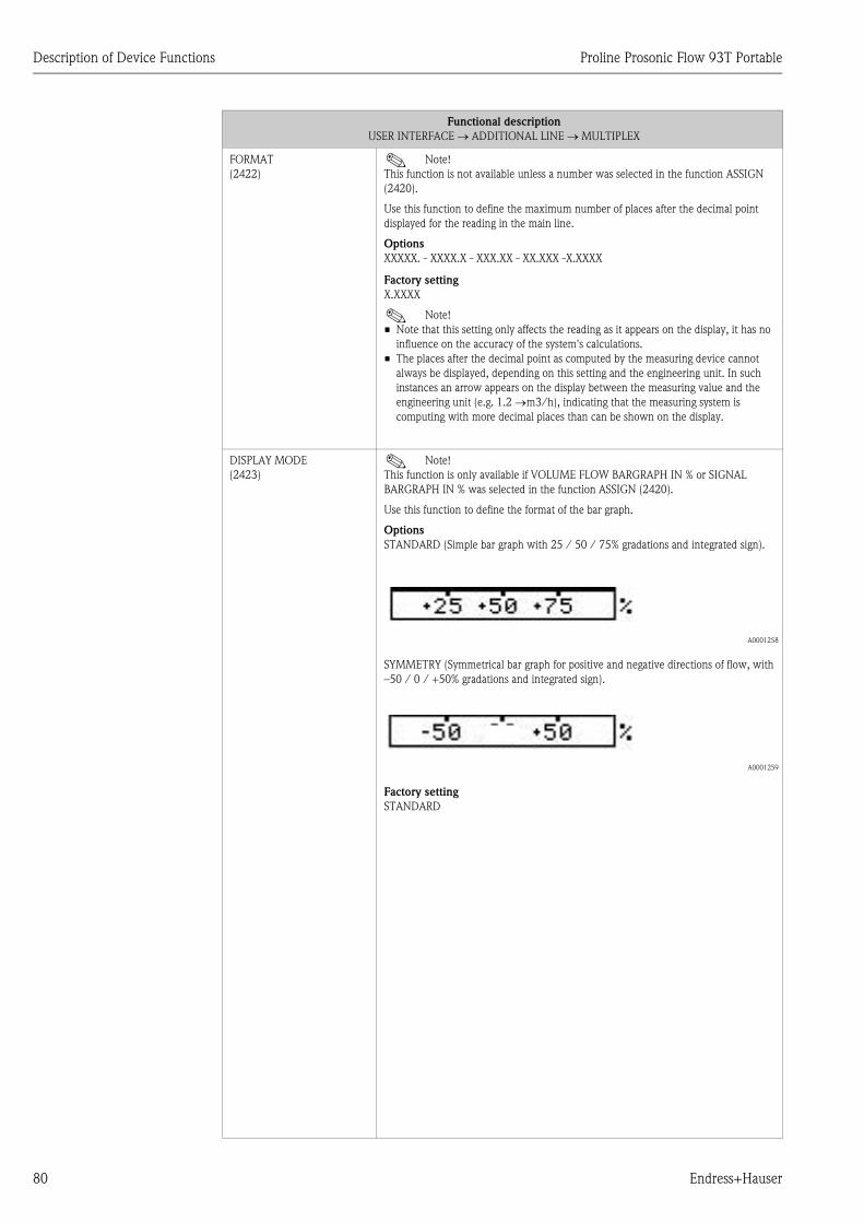
Description of Device Functions Proline Prosonic Flow 93T Portable
80 Endress+Hauser
FORMAT
(2422)! Note!
This function is not available unless a number was selected in the function ASSIGN
(2420).
Use this function to define the maximum number of places after the decimal point
displayed for the reading in the main line.
Options
XXXXX. - XXXX.X - XXX.XX - XX.XXX -X.XXXX
Factory setting
X.XXXX
! Note!
• Note that this setting only affects the reading as it appears on the display, it has no
influence on the accuracy of the system's calculations.
• The places after the decimal point as computed by the measuring device cannot
always be displayed, depending on this setting and the engineering unit. In such
instances an arrow appears on the display between the measuring value and the
engineering unit (e.g. 1.2 →m3/h), indicating that the measuring system is
computing with more decimal places than can be shown on the display.
DISPLAY MODE
(2423)! Note!
This function is only available if VOLUME FLOW BARGRAPH IN % or SIGNAL
BARGRAPH IN % was selected in the function ASSIGN (2420).
Use this function to define the format of the bar graph.
Options
STANDARD (Simple bar graph with 25 / 50 / 75% gradations and integrated sign).
A0001258
SYMMETRY (Symmetrical bar graph for positive and negative directions of flow, with
–50 / 0 / +50% gradations and integrated sign).
A0001259
Factory setting
STANDARD
Functional description
USER INTERFACE → ADDITIONAL LINE → MULTIPLEX

Proline Prosonic Flow 93T Portable Description of Device Functions
Endress+Hauser 81
11.5.4 Group INFORMATION LINE
Function group CONFIGURATION
Functional description
USER INTERFACE → INFORMATION LINE → CONFIGURATION
1 = Main line
2 = Additional line
3 = Information line
A0001253
ASSIGN
(2600)
Use this function to define the display value assigned to the additional line (the bottom
line of the local display) during normal measuring operation.
Options
OFF
VOLUME FLOW (CH1)
VOLUME FLOW IN % (CH1)
SOUND VELOCITY (CH1)
SIGNAL STRENGTH (CH1)
FLOW VELOCITY (CH1)
VOLUME FLOW BARGRAPH IN % (CH1)
SIGNAL BARGRAPH IN % (CH1)
TOTALIZER (1 to 3)
OPERATING/SYSTEM CONDITIONS
FLOW DIRECTION
ACCUMULATOR CHARGE
ACTUAL CURRENT INPUT
Factory setting
ACCUMULATOR CHARGE
100% VALUE
(2601)! Note!
This function is not available unless VOLUME FLOW IN % was selected in the ASSIGN
function (2600).
• VOLUME FLOW IN % (CH1)
• VOLUME FLOW BARGRAPH IN % (CH1)
• SIGNAL BARGRAPH IN % (CH1)
Use this function to define the flow value to be shown on the display as the 100%
value.
User input
5-digit floating-point number
Factory setting
Depends on nominal diameter and country, [value] / [dm3 to m3 or US-gal to US-Mgal]
Corresponds to the factory setting for the full scale value (→ ä 106).
Esc
E+-
1
2
3

Description of Device Functions Proline Prosonic Flow 93T Portable
82 Endress+Hauser
FORMAT
(2602)! Note!
This function is not available unless a number was selected in the function ASSIGN
(2600).
Use this function to define the maximum number of places after the decimal point
displayed for the reading in the additional line.
Options
XXXXX. - XXXX.X - XXX.XX - XX.XXX -X.XXXX
Factory setting
X.XXXX
! Note!
• Note that this setting only affects the reading as it appears on the display, it has no
influence on the accuracy of the system's calculations.
• The places after the decimal point as computed by the measuring device cannot
always be displayed, depending on this setting and the engineering unit. In such
instances an arrow appears on the display between the measuring value and the
engineering unit (e.g. 1.2→ m3/h), indicating that the measuring system is
computing with more decimal places than can be shown on the display.
DISPLAY MODE
(2603)! Note!
This function is only available if VOLUME FLOW BARGRAPH IN % or SIGNAL
BARGRAPH IN % was selected in the function ASSIGN (2600).
Use this function to define the format of the bar graph.
Options
STANDARD (Simple bar graph with 25 / 50 / 75% gradations and integrated sign).
A0001258
SYMMETRY (Symmetrical bar graph for positive and negative directions of flow, with
–50 / 0 / +50% gradations and integrated sign).
A0001259
Factory setting
STANDARD
Functional description
USER INTERFACE → INFORMATION LINE → CONFIGURATION

Proline Prosonic Flow 93T Portable Description of Device Functions
Endress+Hauser 83
Function group MULTIPLEX
Functional description
USER INTERFACE → INFORMATION LINE → MULTIPLEX
ASSIGN
(2620)
Use this function to define a second reading to be displayed in the main line alternately
(every 10 seconds) with the reading defined in the function ASSIGN (2600).
Options
OFF
VOLUME FLOW (CH1)
VOLUME FLOW IN % (CH1)
SOUND VELOCITY (CH1)
SIGNAL STRENGTH (CH1)
FLOW VELOCITY (CH1)
VOLUME FLOW BARGRAPH IN % (CH1)
SIGNAL BARGRAPH IN % (CH1)
TOTALIZER (1 to 3)
OPERATING/SYSTEM CONDITIONS
FLOW DIRECTION
ACTUAL CURRENT INPUT
Factory setting
OFF
! Note!
Multiplex mode is suspended as soon as a fault / notice message is generated. The
message in question appears on the display.
• Fault message (identified by a lightning icon):
– If ON was selected in the function ACKNOWLEDGE FAULTS (8004), multiplex
mode is resumed as soon as the fault has been acknowledged and is no longer
active.
– If OFF was selected in the function ACKNOWLEDGE FAULTS (8004), multiplex
mode is resumed as soon as the fault is no longer active.
• Notice message (identified by an exclamation mark):
– Multiplex mode is resumed as soon as the notice message is no longer active.
If a channel is not visible, it does not appear in the options. Channels can be displayed
or hidden by means of the function MEASUREMENT (6880).
100% VALUE
(2621)! Note!
This function is not available unless VOLUME FLOW IN % was selected in the ASSIGN
function (2620).
• VOLUME FLOW IN % (CH1)
• VOLUME FLOW BARGRAPH IN % (CH1)
• SIGNAL BARGRAPH IN % (CH1)
Use this function to define the flow value to be shown on the display as the 100%
value.
User input
5-digit floating-point number
Factory setting
Depends on nominal diameter and country, [value] / [dm3 to m3 or US-gal to US-Mgal]
Corresponds to the factory setting for the full scale value (→ ä 106).

Description of Device Functions Proline Prosonic Flow 93T Portable
84 Endress+Hauser
FORMAT
(2622)! Note!
This function is not available unless a number was selected in the function ASSIGN
(2620).
Use this function to define the maximum number of places after the decimal point
displayed for the reading in the main line.
Options
XXXXX. - XXXX.X - XXX.XX - XX.XXX -X.XXXX
Factory setting
X.XXXX
! Note!
• Note that this setting only affects the reading as it appears on the display, it has no
influence on the accuracy of the system's calculations.
• The places after the decimal point as computed by the measuring device cannot
always be displayed, depending on this setting and the engineering unit. In such
instances an arrow appears on the display between the measuring value and the
engineering unit (e.g. 1.2→ m3/h), indicating that the measuring system is
computing with more decimal places than can be shown on the display.
DISPLAY MODE
(2623)! Note!
This function is only available if VOLUME FLOW BARGRAPH IN % or SIGNAL
BARGRAPH IN % was selected in the function ASSIGN (2620).
Use this function to define the format of the bar graph.
Options
STANDARD (Simple bar graph with 25 / 50 / 75% gradations and integrated sign).
A0001258
SYMMETRY (Symmetrical bar graph for positive and negative directions of flow, with
–50 / 0 / +50% gradations and integrated sign).
A0001259
Factory setting
STANDARD
Functional description
USER INTERFACE → INFORMATION LINE → MULTIPLEX

Proline Prosonic Flow 93T Portable Description of Device Functions
Endress+Hauser 85
11.6 Block TOTALIZER
11.6.1 Group TOTALIZER (1 to 3)
Function group CONFIGURATION
Functional description
TOTALIZER → TOTALIZER → CONFIGURATION
ASSIGN
(3000)
Use this function to assign a measured variable to the totalizer in question.
Options
OFF
VOLUME FLOW (CH1)
Factory setting
VOLUME FLOW (CH1)
! Note!
• The totalizer is reset to 0 as soon as the selection is changed.
• If you select OFF in the function group CONFIGURATION of the totalizer in
question, only the ASSIGN (3000) function remains visible.
UNIT TOTALIZER
(3001)
Use this function to define the unit for the totalizer's measured variable, as selected
beforehand.
Options
Metric:
cm3; dm3; m3; ml; l; hl; Ml
US:
cc; af; ft3; oz f; gal; Mgal; bbl (normal fluids); bbl (beer); bbl (petrochemicals);
bbl (filling tanks)
Imperial:
gal; Mgal; bbl (beer); bbl (petrochemicals)
Arbitrary unit (from ARBITRARY UNIT function group → ä 71):
_ _ _ _
Factory setting
m3
TOTALIZER MODE
(3002)
Use this function to define how the flow components are to be totaled by the totalizer
in question.
Options
BALANCE
Positive and negative flow components. The positive and negative flow components
are balanced. In other words, net flow in the flow direction is registered.
FORWARD
Positive flow components only
REVERSE
Negative flow components only
Factory setting
Totalizer 1 = BALANCE
Totalizer 2 = FORWARD
Totalizer 3 = REVERSE
RESET TOTALIZER
(3003)
Use this function to reset the sum and the overflow of the totalizer in question to zero.
Options
NO
YES
Factory setting
NO

Description of Device Functions Proline Prosonic Flow 93T Portable
86 Endress+Hauser
Function group OPERATION
11.6.2 Group HANDLING TOTALIZER
Functional description
TOTALIZER → TOTALIZER → OPERATION
SUM
(3040)
Use this function to view the total for the particular totalizer's measured variable
aggregated since measuring commenced. The value can be positive or negative,
depending on the setting selected in the "TOTALIZER MODE" function (3002), and
the direction of flow.
User interface
max. 7-digit floating-point number, including sign and unit (e.g. 15467.04 m3)
! Note!
Multiplex mode is suspended as soon as a fault / notice message is generated. The
message in question appears on the display.
• The effect of the setting in the "TOTALIZER MODE" function (→ ä 85) is as
follows:
– If the setting is "BALANCE", the totalizer balances flow in the positive and
negative directions.
– If the setting is "POSITIVE", the totalizer registers only flow in the positive
direction.
– If the setting is "NEGATIVE", the totalizer registers only flow in the negative
direction.
• The totalizer's response to faults is defined in the "FAILSAFE ALL TOTALIZERS"
function (3801) (→ ä 85).
OVERFLOW
(3041)
Use this function to view the totaled overflow for the particular totalizer aggregated
since measuring commenced.
Total flow quantity is represented by a floating-point number consisting of max.
7 digits. You can use this function to view higher numerical values (>9,999,999) as
overflows. The effective quantity is thus the total of OVERFLOW plus the value
returned by the SUM function.
Example
Reading for 2 overflows: 2 107 dm3 (= 20,000,000 dm3)
The value displayed in the function SUM = 196,845.7 dm3
Effective total quantity = 20,196,845.7 dm3
User interface
Integer with exponent, including sign and unit, e.g. 2 107 dm3
Functional description
TOTALIZER → HANDLING TOTALIZER
RESET ALL TOTALIZERS
(3800)
Use this function to reset the totals (including all overflows) of the totalizers (1 to 3) to
"zero" (= RESET).
Options
NO
YES
Factory setting
NO
FAILSAFE ALL TOTALIZERS
(3801)
Use this function to define the common response of all totalizers (1 to 3) in case of error.
Options
STOP
The totalizers stop if a fault is present.
ACTUAL VALUE
The totalizer continues to count based on the current flow measuring value. The fault
is ignored.
HOLD VALUE
The totalizer continues to count the flow is based on the last valid flow value (before
the fault occurred).
Factory setting
STOP

Proline Prosonic Flow 93T Portable Description of Device Functions
Endress+Hauser 87
11.7 Block OUTPUTS
11.7.1 Group DATA LOGGER
Function group CONFIGURATION
Function group INFORMATION
Functional description
OUTPUTS → DATA LOGGER → CONFIGURATION
TAG NAME
(4900)
Use this function to enter a tag name for the data records (header) to be recorded.
! Note!
After recording, the tag name is saved in the amplifier of the measuring device. The
name should be changed accordingly if the measuring point is changed.
User input
max. 8-character text, permitted characters are: A–Z, 0–9, +,–, punctuation marks
Factory setting
- - - - - - - - (No text)
LOGGING
(4901)
Use this function to start or stop logging data to the USB stick.
Options
OFF
ON
Factory setting
OFF
SYSTEM DATE/TIME
(4902)
Use this function to enter the current date and the current time.
User input
• Day range: 00 to 99
• Month range: 00 to 31
• Year range: 00 to 12
• Meridiem range A or P
LOGGING CYCLE
(4903)Use this function to specify the intervals between the data logging cycles.
User input
Integers, 1 to 99999 s
Factory setting
10 s
DELETE LOG FILES
(4904)
Use this function to clear the entire contents of the USB stick.
Options
NO
YES
Security options
NO
YES
Factory setting
NO
Functional description
OUTPUTS → DATA LOGGER → INFORMATION
LOGGING TIME
(4981)
Use this function to display the time that has elapsed for logging data onto the USB
stick.
User interface
HH:MM:SS
Factory setting
00:00:00

Description of Device Functions Proline Prosonic Flow 93T Portable
88 Endress+Hauser
11.8 Block INPUTS
11.8.1 Group CURRENT INPUT
Function group CONFIGURATION
Functional description
INPUTS → CURRENT INPUT → CONFIGURATION
ASSIGN
(5200)
Use this function to assign a process variable to the current input.
Options
VOLUME FLOW DEVICE 2
OFF
Factory setting
OFF
CURRENT SPAN
(5201)
Use this function to define the current span. The selection specifies the operational
range and the lower and upper signal on alarm.
Options
0–20 mA
4–20 mA
4–20 mA NAMUR
4–20 mA US
0–20 mA (25 mA)
4–20 mA (25 mA)
Factory setting
4–20 mA NAMUR
Current range / operational range (measuring information)
0–20 mA / 0 to 20.5 mA
4–20 mA / 4 to 20.5 mA
4–20 mA NAMUR / 3.8 to 20.5 mA
4–20 mA US / 3.9 to 20.8 mA
0–20 mA (25 mA) / 0 to 24 mA
4–20 mA (25 mA) / 4 to 24 mA
VALUE 0-4 mA
(5202)
Use this function to assign the 0/4 mA current a value.
Options
5-digit floating-point number
Factory setting
0 m3/h
VALUE 20 mA
(5203)
Use this function to assign the 20 mA current a value.
Options
5-digit floating-point number
Factory setting
10 l/s
ERROR VALUE
(5204)
Use this function to enter a defined error value for the process variable in question.
! Note!
If the current value is outside the selected range (see CURRENT SPAN function,
(5201)), the process variable is set to the "error value" defined here and a
corresponding notice message "RANGE CUR. IN
(# 363)" is generated.
User input
5-digit floating-point number
Factory setting
0 l/s

Proline Prosonic Flow 93T Portable Description of Device Functions
Endress+Hauser 89
Function group OPERATION
Functional description
INPUTS → CURRENT INPUT → OPERATION
ACTUAL CURRENT INPUT
(5240)
Use this function to display the actual value of the input current.
User interface
0.0 to 25 mA
SIMULATION CURRENT
INPUT
(5241)
Use this function to activate simulation of the current input.
Options
OFF
ON
Factory setting
OFF
! Note!
• Active simulation is indicated by the notice message "SIM. CURR. INP. 1" (# 661).
• The value output for the simulation at the current input is specified in the VALUE
SIMULATION CURRENT INPUT function (5242).
• The measuring device continues to measure while simulation is in progress, i.e. the
current measuring values are output correctly via the other outputs and the display.
" Caution!
The setting is not saved if the power supply fails.
VALUE SIMULATION
CURRENT INPUT
(5242)
! Note!
This function is not available unless the SIMULATION CURRENT INPUT function
(5241) is switched on.
Use this function to define a freely selectable value (e.g. 12 mA) to be simulated at the
current input. This value is used to test downstream devices and the measuring device
itself.
User input
0.00 to 25.00 mA
Factory setting
0.00 mA or 4 mA (depending on the setting in function 5201)
" Caution!
The setting is not saved if the power supply fails.

Description of Device Functions Proline Prosonic Flow 93T Portable
90 Endress+Hauser
11.9 Block BASIC FUNCTIONS
11.9.1 Group PROCESS PARAMETER
Function group CONFIGURATION
Functional description
BASIC FUNCTION → PROCESS PARAMETER → CONFIGURATION
ASSIGN LOW FLOW CUT
OFF
(6400)
Use this function to assign the switch point for low flow cut off rate suppression.
Options
OFF
VOLUME FLOW
Factory setting
VOLUME FLOW
ON-VALUE LOW FLOW CUT
OFF
(6401)
Use this function to assign a value to the switch-on point for low flow cut off.
Low flow cut off is active if the value entered is not equal to 0. The sign of the flow
value is highlighted on the display to indicate that low flow cut off is active.
User input
5-digit floating-point number
! Note!
The appropriate unit is taken from the function UNIT VOLUME FLOW (0402)
(→ ä 69).
Factory setting
0 l/s
OFF-VALUE LOW FLOW CUT
OFF
(6403)
Use this function to enter the switch-off (b) point for low flow cut off.
Enter the switch-off point as a positive hysteresis (H) from the switch-on point (a).
User input
Integer 0 to 100%
Factory setting
50%
A0001245
Q = Flow [volume/time]
a = ON-VALUE LF CUT OFF (6402) = 200 dm3/h
b = OFF-VALUE LF CUT OFF (6403) = 10%
c = Low flow cut off active
1 = Low flow cut off is switched on at 200 dm3/h
2 = Low flow cut off is switched off at 220 dm3/h
t = Time
1
c c
Q
t
1
2b
a
2
H

Proline Prosonic Flow 93T Portable Description of Device Functions
Endress+Hauser 91
PRESSURE SHOCK
SUPPRESSION
(6404)
The closure of a valve can cause brief but severe movements of the fluid in the piping
system, movements which the measuring system registers. The pulses totaled in this
way result in a totalizer reading error, particularly in the case of batching processes. For
this reason, the measuring device is equipped with pressure shock suppression
(= short-term signal suppression) which can eliminate system-related "disruptions".
! Note!
Note that pressure shock suppression cannot be used unless the low flow cut off is
active, (see function ON-VALUE LF CUT OFF, → ä 90).
Use this function to define the time span for active pressure shock suppression.
Activation of the pressure shock suppression
Pressure shock suppression is activated after the flow falls below the switch-on point of
the low flow cut off (see point 1 in graphic).
While pressure shock suppression is active, the following conditions apply:
• Current output → outputs the current corresponding to zero flow.
• Pulse/Freq.-output → outputs the frequency corresponding to zero flow.
• Flow reading on display = → 0.
• Totalizer reading → the totalizers are pegged at the last correct value.
Deactivation of the pressure shock suppression
The pressure shock suppression is deactivated after the time interval, set in this
function, has passed (see point 2 in graphic).
Factory setting
l/s
! Note!
The actual flow value is displayed and output when the time interval for the pressure
shock suppression has passed and the flow exceeds the switch-off point of the low flow
cut off (see point 3 in graphic).
A0001285-en
User input
max. 4-digit number, incl. unit: 0.00 to 100.0 s
Factory setting
l/s
Functional description
BASIC FUNCTION → PROCESS PARAMETER → CONFIGURATION
nm
a b c
inactive active inactive
t
Pressure shock suppression
Command:Valve closes
Q
Given time
After filling

Description of Device Functions Proline Prosonic Flow 93T Portable
92 Endress+Hauser
Function group ADJUSTMENT
Function group PIPE DATA
Functional description
BASIC FUNCTION → PROCESS PARAMETER → ADJUSTMENT
ZERO POINT ADJUSTMENT
(6480)
Use this function to start zero point adjustment.
! Note!
For information on how to perform a zero point adjustment, see → ä 47.
Options
CANCEL
START
Factory setting
CANCEL
Functional description
BASIC FUNCTION → PROCESS PARAMETER → PIPE DATA
PIPE STANDARD
(6520)
Use this function to select a pipe standard.
Options
OTHERS
DIN: PN10, PN16, 28610, 28614, 28615, 28619
ANSI: SCHEDULE 40, SCHEDULE 80
AWWA: CLASS 50, CLASS 53, CLASS 55
! Note!
The selection specifies the values for the following functions:
• PIPE MATERIAL(6522)
• SOUND VELOCITY PIPE(6524)
• LINER MATERIAL(6528)
If you edit these functions the pipe standard will be reset to the option OTHERS.
Factory setting
DIN PN10
NOMINAL DIAMETER
(6521)! Note!
This function does not appear if the option OTHERS was selected in the function
PIPE STANDARD (6520).
Use this function to select the nominal diameter of the pipe.
Options
OTHERS
DN:
25/1", 40/1½", 50/2", 80/3", 100/4", 150/6", 200/8", 250/10", 300/12",
400/16", 450/18", 500/20", 600/24", 700/28", 750/30", 800/32", 900/36",
1000/40", 1200/48", 1400/54", 1500/60", 1600/64", 1800/72", 2000/80"
! Note!
The selection specifies the values for the following functions:
• CIRCUMFERENCE(6525)
• PIPE DIAMETER(6526)
• WALL THICKNESS(6527)
If you edit these functions the pipe standard will be reset to the option OTHERS and
the function NOMINAL DIAMETER (6521) does not appear.
Factory setting
80/3"

Proline Prosonic Flow 93T Portable Description of Device Functions
Endress+Hauser 93
PIPE MATERIAL
(6522)
This function displays the pipe material determined via the value entered in the
function PIPE STANDARD (6520). If you edit the predetermined value the pipe
standard will be reset to the option OTHERS and the function NOMINAL DIAMETER
(6521) does not appear.
If a pipe standard was not available for selection and the selection OTHER was made in
the function PIPE STANDARD (6520) the pipe material must be entered here.
Options
CARBON STEEL, DUCTILE IRON, STAINLESS STEEL, SS ANSI 304, SS ANSI 316,
SS ANSI 347, SS ANSI 410, SS ANSI 430, ALLOY C, PVC, PE, LDPE, HDPE, GRP,
PVDF, PA, PP, PTFE, GLASS PYREX, ASBESTOS CEMENT, OTHER
Factory setting
STAINLESS STEEL
REFERENCE VALUE
(6523)
Use this function to enter the thickness of the reference component (e.g. flange) as the
basis for measuring the sound velocity of the pipe.
! Note!
This function does not appear unless the option SOUND VELOCITY PIPE was selected
in the function MEASUREMENT (6880, → ä 99).
User input
5-digit floating-point number, [unit]
Factory setting
5 mm
SOUND VELOCITY PIPE
(6524)
This function displays the sound velocity in the pipe determined via the value entered
in the function PIPE STANDARD (6520). If you edit the predetermined value the pipe
standard will be reset to the option OTHERS and the function NOMINAL DIAMETER
(6521) does not appear.
If a pipe standard was not available for selection and the selection OTHER was made in
the function PIPE STANDARD (6520) the sound velocity must be entered here.
Measuring the sound velocity in the pipe
If the sound velocity in the pipe is unknown, it can be measured. To do so, select the
option SOUND VELOCITY PIPE in the function MEASUREMENT (6880, → ä 99).
The sound velocity in the pipe is measured by calling up the function SOUND
VELOCITY PIPE (6524). The measured sound velocity, the signal strength and a bar
graph appear on the local display. The measurement is valid if 100% is achieved in the
bar graph. If you confirm the function with the F key, the SAVE prompt appears. To
accept the measured sound velocity, select the option YES by means of the O or S
key.
! Note!
• To measure the sound velocity, you require the ultrasonic sensors "DDU18" which
you can order as an accessory from Endress+Hauser.
• A reference value is used as a basis for measuring the sound velocity. This reference
value can be edited (see REFERENCE VALUE function, 6523).
User input
Fixed-point number 800 to 6500 m/s
Factory setting
3120 m/s
Functional description
BASIC FUNCTION → PROCESS PARAMETER → PIPE DATA
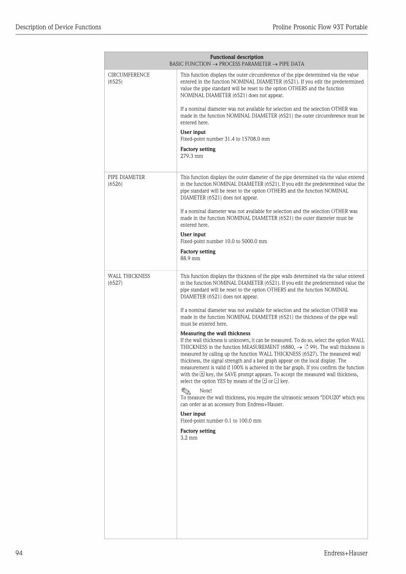
Description of Device Functions Proline Prosonic Flow 93T Portable
94 Endress+Hauser
CIRCUMFERENCE
(6525)
This function displays the outer circumference of the pipe determined via the value
entered in the function NOMINAL DIAMETER (6521). If you edit the predetermined
value the pipe standard will be reset to the option OTHERS and the function
NOMINAL DIAMETER (6521) does not appear.
If a nominal diameter was not available for selection and the selection OTHER was
made in the function NOMINAL DIAMETER (6521) the outer circumference must be
entered here.
User input
Fixed-point number 31.4 to 15708.0 mm
Factory setting
279.3 mm
PIPE DIAMETER
(6526)
This function displays the outer diameter of the pipe determined via the value entered
in the function NOMINAL DIAMETER (6521). If you edit the predetermined value the
pipe standard will be reset to the option OTHERS and the function NOMINAL
DIAMETER (6521) does not appear.
If a nominal diameter was not available for selection and the selection OTHER was
made in the function NOMINAL DIAMETER (6521) the outer diameter must be
entered here.
User input
Fixed-point number 10.0 to 5000.0 mm
Factory setting
88.9 mm
WALL THICKNESS
(6527)
This function displays the thickness of the pipe walls determined via the value entered
in the function NOMINAL DIAMETER (6521). If you edit the predetermined value the
pipe standard will be reset to the option OTHERS and the function NOMINAL
DIAMETER (6521) does not appear.
If a nominal diameter was not available for selection and the selection OTHER was
made in the function NOMINAL DIAMETER (6521) the thickness of the pipe wall
must be entered here.
Measuring the wall thickness
If the wall thickness is unknown, it can be measured. To do so, select the option WALL
THICKNESS in the function MEASUREMENT (6880, → ä 99). The wall thickness is
measured by calling up the function WALL THICKNESS (6527). The measured wall
thickness, the signal strength and a bar graph appear on the local display. The
measurement is valid if 100% is achieved in the bar graph. If you confirm the function
with the F key, the SAVE prompt appears. To accept the measured wall thickness,
select the option YES by means of the O or S key.
! Note!
To measure the wall thickness, you require the ultrasonic sensors "DDU20" which you
can order as an accessory from Endress+Hauser.
User input
Fixed-point number 0.1 to 100.0 mm
Factory setting
3.2 mm
Functional description
BASIC FUNCTION → PROCESS PARAMETER → PIPE DATA

Proline Prosonic Flow 93T Portable Description of Device Functions
Endress+Hauser 95
Function group LIQUID DATA
LINER MATERIAL
(6528)
This function displays the liner material of the pipe determined via the value entered in
the function PIPE STANDARD (6520). If you edit the predetermined value the pipe
standard will be reset to the option OTHERS and the function NOMINAL DIAMETER
(6521) does not appear.
If a pipe standard was not available for selection and the selection OTHERS was made
in the function PIPE STANDARD (6520) the liner material must be specified here.
Options
LINER NONE
MORTAR
TAR EPOXY
OTHERS
Factory setting
LINER NONE
SOUND VELOCITY LINER
(6529)! Note!
This function does not appear if the option LINER NONE was selected in the function
LINER MATERIAL (6528).
This function displays the sound velocity of the liner determined via the value entered
in the function LINER MATERIAL (6528). If you edit the predetermined value the
liner material will be reset to the option OTHERS.
If a liner material was not available for selection and the selection OTHER was made in
the function LINER MATERIAL (6528) the sound velocity of the liner must be entered
here.
User input
Fixed-point number 800 to 6500 m/s
Factory setting
Depending on the selection in the function LINER MATERIAL (6528)
LINER THICKNESS
(6528)! Note!
This function does not appear if the option LINER NONE was selected in the function
LINER MATERIAL (6528).
Use this function to enter the thickness of the liner.
User input
Fixed-point number 0.1 to 100.0 mm
Factory setting
0 mm
Functional description
BASIC FUNCTIONS → PROCESS PARAMETER → LIQUID DATA
LIQUID
(6540)
Use this function to select the liquid in the pipe.
Options
WATER, SEA WATER, DISTILLED WATER, AMMONIA, ALCOHOL, BENZENE,
BROMIDE, ETHANOL, GLYCOL, KEROSENE, MILK, METHANOL, TOLUOL,
LUBRICATING OIL, FUEL OIL, PETROL, OTHER
! Note!
The selection specifies the values for the sound velocity and viscosity. If OTHER is
selected, these must be entered via the SOUND VELOCITY LIQUID (6542) and
VISCOSITY (6543) functions.
Factory setting
Water
Functional description
BASIC FUNCTION → PROCESS PARAMETER → PIPE DATA

Description of Device Functions Proline Prosonic Flow 93T Portable
96 Endress+Hauser
TEMPERATURE
(6541)
Use this function to enter the process temperature of the liquid. Via the sound velocity,
the value influences the determination of the sensor distance. Enter the process
temperature at normal operating conditions to achieve an optimum configuration of
the measuring system.
User input
Fixed-point number –273.15 to 726.85 °C (0 to 1000 K)
Factory setting
20 °C
SOUND VELOCITY LIQUID
(6542)
This function displays the sound velocity of the liquid. This is determined by the values
entered in the LIQUID (6540) and TEMPERATURE (6541) functions. If you edit the
predetermined value the function LIQUID (6540) will be set to the option OTHERS.
The sound velocity of the liquid has to be entered if the liquid is not available for
selection in the function LIQUID (6540) and the OTHERS option was selected.
Measuring the sound velocity of the liquid
If the sound velocity of the liquid is unknown, it can be measured. To do so, select the
option SOUND VELOCITY LIQUID in the function MEASUREMENT (6880,
→ ä 99). The sound velocity in the liquid is measured by calling up the function
SOUND VELOCITY LIQUID (6542). The result of the measurement appears on the
local display. If you confirm the function with the F key, the SAVE prompt appears. To
accept the measured sound velocity, select the option YES by means of the O or S
key.
! Note!
To measure the sound velocity, you require the ultrasonic sensors "DDU18" which you
can order as an accessory from Endress+Hauser.
Transmitter search range:
The measuring device searches for the measuring signal within a defined sound
velocity range. You specify the search range in the SOUND VELOCITY NEGATIVE
(6545) and SOUND VELOCITY POSITIVE (6546) functions. An error message is
displayed if the sound velocity of the liquid exceeds the search range.
! Note!
We recommend you select a smaller search range in the event of unfavorable signal
conditions (signal strength < 50%).
A0001246
1. Sound velocity of the liquid
2. Lower search range: is specified in the
SOUND VELOCITY NEGATIVE (6545) function
3. Upper search range: is specified in the SOUND VELOCITY POSITIVE (6546)
function
User input
Fixed-point number 400 to 3000 m/s
Factory setting
1485 m/s
Functional description
BASIC FUNCTIONS → PROCESS PARAMETER → LIQUID DATA
1
v [m/s]2
0-1000
3
0-1000

Proline Prosonic Flow 93T Portable Description of Device Functions
Endress+Hauser 97
VISCOSITY
(6543)
This function displays the viscosity of the liquid. This is determined via the values
entered in the LIQUID (6540) and TEMPERATURE (6541) functions.
If you edit the predetermined value the function LIQUID (6540) will be set to the
option OTHERS.
The viscosity has to be entered if the liquid is not available for selection in the function
LIQUID (6540) and the OTHERS option was selected.
User input
Fixed-point number 0.0 to 5000.0 mm2/s
Factory setting
l mm2/s
SOUND VELOCITY
NEGATIVE
(6545)
Use this function to specify the lower search range for the sound velocity of the liquid.
User input
Fixed-point number 0 to 1000 m/s
Factory setting
500 m/s
! Note!
Please refer to the explanations in the function SOUND VELOCITY LIQUID (6542).
SOUND VELOCITY POSITIVE
(6546)
Use this function to specify the upper search range for the sound velocity of the liquid.
User input
Fixed-point number 0 to 1000 m/s
Factory setting
300 m/s
! Note!
Please refer to the explanations in the function SOUND VELOCITY LIQUID (6542).
Functional description
BASIC FUNCTIONS → PROCESS PARAMETER → LIQUID DATA

Description of Device Functions Proline Prosonic Flow 93T Portable
98 Endress+Hauser
11.9.2 Group SYSTEM PARAMETER
Function group CONFIGURATION
Functional description
BASIC FUNCTION → SYSTEM PARAMETER → CONFIGURATION
INSTALLATION DIRECTION
SENSOR
(6600)
Use this function to reverse the sign of the flow quantity, if necessary.
Options
NORMAL
INVERSE
Factory setting
NORMAL
FLOW DAMPING
(6603)
The system damping acts on all functions and outputs of the measuring device.
Use this function to set the filter depth of the digital filter. This reduces the sensitivity
of the measuring signal to interference peaks (e.g. high solids content, gas bubbles in
the fluid, etc.). The system reaction time increases with the filter setting.
User input
0 to 100 s
Factory setting
0 s
POSITIVE ZERO RETURN
(6605)
Use this function to interrupt evaluation of measured variables. This is necessary when
a piping system is being cleaned, for example. This setting acts on all function and
outputs of the measuring device.
Options
OFF
ON → Signal output is set to the "ZERO FLOW" value.
Factory setting
OFF

Proline Prosonic Flow 93T Portable Description of Device Functions
Endress+Hauser 99
11.9.3 Group SENSOR DATA
Function group SENSOR PARAMETER
Functional description
BASIC FUNCTION → SENSOR DATA → SENSOR PARAMETER
MEASUREMENT
(6880)
Use this function to select the measuring method or the type of mounting.
Options
OFF
CLAMP ON
INSERTION (is not supported by the measuring device)
SOUND VELOCITY LIQUID
SOUND VELOCITY PIPE
WALL THICKNESS
Factory setting
CLAMP ON
SENSOR TYPE
(6681)! Note!
This function is only available if the OFF setting was not selected in the function
MEASUREMENT.
Use this function to select the sensor type.
Options
W-CL-05F-L-B 1)
W-CL-1F-L-B 1)
W-CL-2F-L-B 1)
P-CL-05F-L-B 1)
P-CL-1F-L-B 1)
P-CL-2F-L-B 1)
U-CL-2F-L-A 1)
P-CL-6F-L-D 1)
P-CL-6F-M-D 1)
P-CL-05F-M-B 1)
P-CL-1F-M-B 1)
P-CL-2F-M-B 1)
W-IN-1F-L-B 2)
P-CL-1S-L-B 3)
P-CL-1S-M-B 3)
P-CL-4W-L-B4)
Factory setting
W-CL-2F-L-B
• 1)This option is not available unless CLAMP ON was selected in the function
MEASUREMENT.
• 2) This option is not available unless INSERTION was selected in the function
MEASUREMENT.
• 3) This option is not available unless SOUND VELOCITY LIQUID was selected in
the function MEASUREMENT.
• 4) This option is not available unless SOUND VELOCITY PIPE or WALL
THICKNESS was selected in the function MEASUREMENT.

Description of Device Functions Proline Prosonic Flow 93T Portable
100 Endress+Hauser
SENSOR CONFIGURATION
(6882)
Use this function to select the configuration for the ultrasonic sensors, e.g. the number
of traverses (in the Clamp On version).
! Note!
This function is not available unless one of the following options was selected in the
function MEASUREMENT (6880):
• CLAMP ON
• SOUND VELOCITY LIQUID
• INSERTION (is not supported by the measuring device)
Options
NO. TRAVERSE: 1 1)
NO. TRAVERSE: 2 2)
SINGLE PATH 3) (is not supported by the measuring device)
DUAL PATH 3) (is not supported by the measuring device)
Factory setting
NO. TRAVERSE: 2
• 1) This option is not available unless CLAMP ON or SOUND VELOCITY LIQUID
was selected in the function MEASUREMENT.
• 2) This option is not available unless CLAMP ON was selected in the function
MEASUREMENT.
• 3) This option is not available unless INSERTION was selected in the function
MEASUREMENT.
! Note!
The setting "NO. TRAVERSE: 2" is required for sensors with a nominal diameter range
from DN15 to DN 65.
CABLE LENGTH
(6882)
Use this function to select the length of the sensor cable.
Options
LENGTH 5 m/15 feet
LENGTH 10 m/30 feet
Factory setting
LENGTH 5 m/15 feet
POSITION SENSOR
(6884)
Use this function to view the position of both sensors on the rail.
User interface
5-digit number combination
WIRE LENGTH
(6885)
The wire length for assembling the sensors at the correct distance apart appears on the
display.
User interface
max. 5-digit number, including unit (e.g. 200 mm)
SENSOR DISTANCE
(6886)
The distance between sensor 1 and sensor 2 as a length measurement appears on the
display.
User interface
max. 5-digit number, including unit (e.g. 200 mm)
ARC LENGTH
(6887)
The arc length on the pipe appears on the display.
User interface
max. 5-digit number, including unit (e.g. 200 mm)
PATH LENGTH
(6888)
The path length appears on the display.
User interface
max. 5-digit number, including unit (e.g. 200 mm)
Functional description
BASIC FUNCTION → SENSOR DATA → SENSOR PARAMETER

Proline Prosonic Flow 93T Portable Description of Device Functions
Endress+Hauser 101
Function group CALIBRATION DATA
Functional description
BASIC FUNCTIONS → SENSOR DATA → CALIBRATION DATA
P-FACTOR
(6890)
This function displays the p-factor.
The p-factor indicates the influence of the velocity distribution of the flow profile inside
the pipe; it is dependent on the Reynolds number. The p-factor varies in the range
0.75 to 0.95. If the displayed value ranges between 0.75 and 0.94 the measurement
will have a reduced linearity.
ZERO POINT
(6891)
Use this function to call up or manually change the zero point correction currently
being used.
User input
5-digit floating-point number, including unit and sign (e.g. +10.0 ns)
CORRECTION FACTOR
(6893)
Use this function to enter a correction factor at the client's site.
User input
5-digit floating-point number
Factory setting
1.0000 (= no correction)
DEVIATION SENSOR
DISTANCE
(6894)
! Note!
This option is not available unless INSERTION was selected in the function
MEASUREMENT (6880). (is not supported by the measuring device)
Use this function to enter a deviation value for the sensor distance.
User input
5-digit floating-point number, including unit and sign (e.g. +2.0000 mm)
Factory setting
0 mm
DEVIATION ARC LENGTH
(6895)
Use this function to enter a deviation value for the arc length.
! Note!
This function is not available unless INSERTION was set in the function
MEASUREMENT (6880) and the DUAL PATH option was selected in the function
SENSOR CONFIGURATION (6882).
User input
5-digit floating-point number, including unit and sign (e.g. +2.0000 mm)
Factory setting
0 mm
DEVIATION PATH LENGTH
(6896)! Note!
This option is not available unless INSERTION was selected in the function
MEASUREMENT (6880). (is not supported by the measuring device)
Use this function to enter a deviation value for the path length.
User input
5-digit floating-point number, including unit and sign (e.g. +2.0000 mm)
Factory setting
0 mm

Description of Device Functions Proline Prosonic Flow 93T Portable
102 Endress+Hauser
11.10 Block SUPERVISION
11.10.1 Group SYSTEM
Function group CONFIGURATION
Functional description
SUPERVISION → SYSTEM → CONFIGURATION
ASSIGN SYSTEM ERROR
(8000)
Use this function to view all system errors and the associated error categories (fault
message or notice message). If you select a single system error you can change
its error category.
User interface
CANCEL
List of system errors with an icon preceding each entry.
! Note!
• Press the F key twice to call up the function ERROR CATEGORY (8001).
• Use the Q key combination or select "CANCEL" in the system error list to exit the
function.
• A list of possible system errors is provided on → ä 52.
ERROR CATEGORY
(8001)
Use this function to define whether a system error triggers a notice message or a fault
message. If you select "FAULT MESSAGES", all outputs respond to an error in
accordance with their defined error response patterns.
Options
NOTICE MESSAGES (display only)
FAULT MESSAGES (outputs and display)
! Note!
Press the F key twice to call up the function ASSIGN SYSTEM ERROR (8000).
ASSIGN PROCESS ERROR
(8002)
Use this function to view all process errors and the associated error categories (fault
message or notice message). If you select a single process error you can change
its error category.
User interface
CANCEL
List of process errors with an icon preceding each entry.
! Note!
• Press the F key twice to call up the function ERROR CATEGORY (8003).
• Use the Q key combination or select "CANCEL" in the system error list to exit the
function.
• A list of possible process errors is provided on → ä 54.
ERROR CATEGORY
(8003)
Use this function to define whether a process error triggers a notice message or a fault
message. If you select "FAULT MESSAGES", all outputs respond to an error in
accordance with their defined error response patterns.
Options
NOTICE MESSAGES (display only)
FAULT MESSAGES (outputs and display)
! Note!
Press the F key twice to call up the function
ASSIGN PROCESS ERROR (8002).

Proline Prosonic Flow 93T Portable Description of Device Functions
Endress+Hauser 103
Function group OPERATION
ACKNOWLEDGE FAULT
(8004)
Use this function to define the measuring device's response to fault messages.
Options
OFF
The measuring device resumes normal operation when the fault is rectified. The fault
message disappears automatically.
ON
The measuring device resumes normal operation when the fault is rectified. The fault
message has to be acknowledged by pressing the F key on the local display.
Factory setting
OFF
ALARM DELAY
(8005)
Use this function to specify a time period for suppressing the appearance of fault or
notice messages.
Depending on the setting and the type of error, this suppression acts on:
• Display
• Relay output
• Current output
• Frequency output
User input
0 to 100 s (in steps of one second)
Factory setting
0 s
" Caution!
If this function is activated, error and notice messages are delayed by the time
corresponding to the setting before being forwarded to the higher-order controller
(process controller, etc.).
It is therefore imperative to check in advance in order to make sure whether a delay of
this nature could affect the safety requirements of the process. If error and notice
messages cannot be suppressed, a value of 0 seconds must be entered here.
Functional description
SUPERVISION → SYSTEM → OPERATION
ACTUAL SYSTEM
CONDITION
(8040)
Use this function to check the present system condition.
User interface
"SYSTEM OK" or the fault / notice message with the highest priority.
PREVIOUS SYSTEM
CONDITIONS
(8041)
Use this function to view the fifteen most recent error and notice messages since
measuring last started.
User interface
The last 15 fault/notice messages appear on the display.
SIMULATION FAILSAFE
MODE
(8042)
Use this function to set all inputs, outputs and totalizers to their defined failsafe modes,
in order to check whether they respond correctly. During this time, the words
"SIMULATION FAILSAFE MODE" appear on the display.
Options
ON
OFF
FAILURE (CH1)
Factory setting
OFF
Functional description
SUPERVISION → SYSTEM → CONFIGURATION

Description of Device Functions Proline Prosonic Flow 93T Portable
104 Endress+Hauser
11.10.2 Group VERSION INFO
Function group DEVICE
Function group SENSOR
SIMULATION MEASURAND
(8043)! Note!
This function is available in the SYSTEM group.
Use this function to set all inputs, outputs and totalizers to their defined flow-response
modes, in order to check whether they respond correctly. During this time, the words
"SIMULATION MEASURAND" appear on the display.
Options
OFF
VOLUME FLOW (CH1)
SOUND VELOCITY (CH1)
Factory setting
OFF
" Caution!
• The measuring device cannot be used for measuring while this simulation is in
progress.
• The setting is not saved if the power supply fails.
VALUE SIMULATION
MEASURAND
(8044)
! Note!
• This function is available in the SYSTEM group.
• The function is not visible unless the function SIMULATION MEASURAND (8043)
is active.
Use this function to specify a selectable value (e.g. 12 m3/s). This is used to test the
associated functions in the device itself and downstream signal loops.
User input
5-digit floating-point number, [unit]
Factory setting
0 [unit]
" Caution!
• The setting is not saved if the power supply fails.
• The appropriate unit is taken from the function group SYSTEM UNITS (ACA)
(→ ä 69).
SYSTEM RESET
(8046)
Use this function to perform a reset of the measuring system.
Options
NO
RESTART SYSTEM (restart without interrupting power supply)
Factory setting
NO
Functional description
SUPERVISION → VERSION INFO → DEVICE
DEVICE SOFTWARE
(8100)
Displays the current device software version.
Functional description
SUPERVISION → VERSION INFO → SENSOR
SERIAL NUMBER
(8200)
Use this function to view the current serial number of the sensor.
Functional description
SUPERVISION → SYSTEM → OPERATION

Proline Prosonic Flow 93T Portable Description of Device Functions
Endress+Hauser 105
Function group AMPLIFIER
Function group I/O MODULE
Function group I/O SUBMODULE 1
Function group I/O SUBMODULE 2
Functional description
SUPERVISION → VERSION INFO → AMPLIFIER
SOFTWARE REVISION
NUMBER AMPLIFIER
(8222)
Use this function to view the software revision number of the amplifier.
LANGUAGE GROUP
(8226)
Use this function to view the language group.
! Note!
• You can change the language group via the operating program "FieldCare".
• The following language groups are available:
– WEST EU / USA
– EAST EU / SCAND.
– ASIA
– CHINA
Functional description
SUPERVISION → VERSION INFO → I/O MODULE
I/O MODULE TYPE
(8300)
Use this function to view the configuration of the I/O module.
SOFTWARE REVISION
NUMBER I/O MODULE
(8303)
Use this function to view the software revision number of the I/O module.
Functional description
SUPERVISION → VERSION INFO → I/O SUBMODULE 1
SUB I/O TYPE
(8320)
Use this function to view the configuration of I/O submodule 1 (current input).
SOFTWARE REVISION
NUMBER SUB I/O TYPE
(8323)
Use this function to view the software revision number of I/O submodule 1.
Functional description
SUPERVISION → VERSION INFO → I/O SUBMODULE 2
SUB I/O TYPE
(8340)
Use this function to view the configuration of I/O submodule 2 (data logger).
SOFTWARE REVISION
NUMBER SUB I/O TYPE
(8343)
Use this function to view the software revision number of I/O submodule 2.

Factory settings Proline Prosonic Flow 93T Portable
106 Endress+Hauser
12 Factory settings
12.1 SI units (not for USA and Canada)
12.1.1 Units of length and temperature
12.1.2 Language
12.2 US units (for USA and Canada only)
12.2.1 Units of length and temperature
12.2.2 Language
Unit
Temperature ° C
Length mm
Country Language Country Language
Australia English Norway Norsk
Belgium English Austria Deutsch
Denmark English Poland Polski
Germany Deutsch Portugal Portugues
England English Sweden Svenska
Finland Suomi Switzerland Deutsch
France Francais Singapore English
The Netherlands Nederlands Spain Espanol
Hong Kong English South Africa English
India English Thailand English
Italy Italiano Czech Republic Cesky
Luxembourg Francais Hungary English
Malaysia English Other countries English
Unit
Temperature °F
Length Inch
Language
USA English
Canada English

Proline Prosonic Flow 93T Portable Index
Endress+Hauser 107
Index
AAccess code (2020) . . . . . . . . . . . . . . . . . . . . . . . . . . . . . . 73
Access code counter (2023). . . . . . . . . . . . . . . . . . . . . . . . 74
Accessories . . . . . . . . . . . . . . . . . . . . . . . . . . . . . . . . . . . . 50
Acknowledge fault (8004) . . . . . . . . . . . . . . . . . . . . . . . . 103
Actual current input (5240). . . . . . . . . . . . . . . . . . . . . . . . 89
Actual system condition (8040) . . . . . . . . . . . . . . . . . . . . 103
Additional configuration (function group). . . . . . . . . . . . . . 70
Additional line
100% value (2401) . . . . . . . . . . . . . . . . . . . . . . . . . . . 77
Assign (2400) . . . . . . . . . . . . . . . . . . . . . . . . . . . . . . . 77
Configuration . . . . . . . . . . . . . . . . . . . . . . . . . . . . . . . 77
Display mode (2403) . . . . . . . . . . . . . . . . . . . . . . . . . . 78
Format (2402) . . . . . . . . . . . . . . . . . . . . . . . . . . . . . . . 78
Additional line (Multiplex)
100% value (2421) . . . . . . . . . . . . . . . . . . . . . . . . . . . 79
Assign (2420) . . . . . . . . . . . . . . . . . . . . . . . . . . . . . . . 79
Display mode (2423) . . . . . . . . . . . . . . . . . . . . . . . . . . 80
Format (2422) . . . . . . . . . . . . . . . . . . . . . . . . . . . . . . . 80
Adjustment (function group) . . . . . . . . . . . . . . . . . . . . . . . 92
Alarm delay (8005) . . . . . . . . . . . . . . . . . . . . . . . . . . . . . 103
Ambient temperature range . . . . . . . . . . . . . . . . . . . . . . . . 61
Amplifier (function group) . . . . . . . . . . . . . . . . . . . . . . . . 105
Applications . . . . . . . . . . . . . . . . . . . . . . . . . . . . . . . . . 5, 57
Applicator (selection and configuration software) . . . . . . . . 51
Approvals . . . . . . . . . . . . . . . . . . . . . . . . . . . . . . . . . . . 9, 64
Arbitrary unit
Function group . . . . . . . . . . . . . . . . . . . . . . . . . . . . . . 71
Arbitrary units (function group) . . . . . . . . . . . . . . . . . . . . . 71
Arc length (6887) . . . . . . . . . . . . . . . . . . . . . . . . . . . . . . 100
Assign (3000) . . . . . . . . . . . . . . . . . . . . . . . . . . . . . . . . . . 85
Assign (5200) . . . . . . . . . . . . . . . . . . . . . . . . . . . . . . . . . . 88
Assign low flow cut off (6400). . . . . . . . . . . . . . . . . . . . . . 90
Assign process error (8002) . . . . . . . . . . . . . . . . . . . . . . . 102
Assign system error (8000) . . . . . . . . . . . . . . . . . . . . . . . 102
BBacklight (2004) . . . . . . . . . . . . . . . . . . . . . . . . . . . . . . . . 73
Basic configuration (function group). . . . . . . . . . . . . . . . . . 72
Basic functions (block). . . . . . . . . . . . . . . . . . . . . . . . . . . . 90
Battery charging . . . . . . . . . . . . . . . . . . . . . . . . . . . . . . . . 49
Block
Basic functions. . . . . . . . . . . . . . . . . . . . . . . . . . . . . . . 90
Inputs . . . . . . . . . . . . . . . . . . . . . . . . . . . . . . . . . . . . . 88
Measured variables . . . . . . . . . . . . . . . . . . . . . . . . . . . 68
Outputs . . . . . . . . . . . . . . . . . . . . . . . . . . . . . . . . . . . . 87
Quick Setup. . . . . . . . . . . . . . . . . . . . . . . . . . . . . . . . . 71
Supervision . . . . . . . . . . . . . . . . . . . . . . . . . . . . . . . . 102
Totalizer . . . . . . . . . . . . . . . . . . . . . . . . . . . . . . . . . . . 85
User interface . . . . . . . . . . . . . . . . . . . . . . . . . . . . . . . 72
CCable length (6882) . . . . . . . . . . . . . . . . . . . . . . . . . . . . 100
Calibration data (function group) . . . . . . . . . . . . . . . . . . . 101
CE mark (Declaration of Conformity). . . . . . . . . . . . . . . . . . 9
Certificates . . . . . . . . . . . . . . . . . . . . . . . . . . . . . . . . . . 9, 64
Circumference (6525) . . . . . . . . . . . . . . . . . . . . . . . . . . . . 94
Cleaning . . . . . . . . . . . . . . . . . . . . . . . . . . . . . . . . . . . . . . 49
Commissioning
Quick Setup "Pulsating Flow" . . . . . . . . . . . . . . . . . . . . 44
Configuration
Additional line . . . . . . . . . . . . . . . . . . . . . . . . . . . . . . . 77
Current input) . . . . . . . . . . . . . . . . . . . . . . . . . . . . . . . 88
Data logger . . . . . . . . . . . . . . . . . . . . . . . . . . . . . . . . . 87
Information line . . . . . . . . . . . . . . . . . . . . . . . . . . . . . . 81
Main line . . . . . . . . . . . . . . . . . . . . . . . . . . . . . . . . . . . 75
Process parameter . . . . . . . . . . . . . . . . . . . . . . . . . . . . 90
Supervision . . . . . . . . . . . . . . . . . . . . . . . . . . . . . . . . 102
System parameter. . . . . . . . . . . . . . . . . . . . . . . . . . . . . 98
System units . . . . . . . . . . . . . . . . . . . . . . . . . . . . . . . . 69
Totalizer) . . . . . . . . . . . . . . . . . . . . . . . . . . . . . . . . . . . 85
Connecting cable. . . . . . . . . . . . . . . . . . . . . . . . . . . . . . . . 59
Contrast LCD (2003). . . . . . . . . . . . . . . . . . . . . . . . . . . . . 73
Control (group) . . . . . . . . . . . . . . . . . . . . . . . . . . . . . . . . . 72
Correction factor (6893) . . . . . . . . . . . . . . . . . . . . . . . . . 101
Coupling fluid . . . . . . . . . . . . . . . . . . . . . . . . . . . . . . . . . . 49
C-Tick mark . . . . . . . . . . . . . . . . . . . . . . . . . . . . . . . . . . . . 9
Current output (group) . . . . . . . . . . . . . . . . . . . . . . . . . . . 88
Current span (5201) . . . . . . . . . . . . . . . . . . . . . . . . . . . . . 88
DData logger . . . . . . . . . . . . . . . . . . . . . . . . . . . . . . . . . . . . 58
Data logger (data exchange) . . . . . . . . . . . . . . . . . . . . . . . . 48
Data logger (group) . . . . . . . . . . . . . . . . . . . . . . . . . . . . . . 87
DDU18 sound velocity sensor . . . . . . . . . . . . . . . . . . . . . . 28
DDU20 wall thickness sensor . . . . . . . . . . . . . . . . . . . . . . 29
Declaration of Conformity (CE mark) . . . . . . . . . . . . . . . . . . 9
Define private code (2021) . . . . . . . . . . . . . . . . . . . . . . . . 74
Degree of protection . . . . . . . . . . . . . . . . . . . . . . . . . . . . . 61
Delete log files (4904) . . . . . . . . . . . . . . . . . . . . . . . . . . . . 87
Designated use . . . . . . . . . . . . . . . . . . . . . . . . . . . . . . . . . . 5
Deviation arc length (6895) . . . . . . . . . . . . . . . . . . . . . . . 101
Deviation path length (6896) . . . . . . . . . . . . . . . . . . . . . . 101
Deviation sensor distance (6894) . . . . . . . . . . . . . . . . . . . 101
Device (function group) . . . . . . . . . . . . . . . . . . . . . . . . . . 104
Device designation . . . . . . . . . . . . . . . . . . . . . . . . . . . . . . . 7
Device software (8100) . . . . . . . . . . . . . . . . . . . . . . . . . . 104
Display . . . . . . . . . . . . . . . . . . . . . . . . . . . . . . . . . . . . . . . 63
Display and operating elements . . . . . . . . . . . . . . . . . . . . . 33
Display damping (2002). . . . . . . . . . . . . . . . . . . . . . . . . . . 72
Display elements . . . . . . . . . . . . . . . . . . . . . . . . . . . . . . . . 63
Disposal. . . . . . . . . . . . . . . . . . . . . . . . . . . . . . . . . . . . . . . 56
EElectrical connection
Potential equalization . . . . . . . . . . . . . . . . . . . . . . . . . . 32
Electromagnetic compatibility (EMC) . . . . . . . . . . . . . . . . . 61
Error category (8001) . . . . . . . . . . . . . . . . . . . . . . . . . . . 102
Error category (8003) . . . . . . . . . . . . . . . . . . . . . . . . . . . 102
Error messages
Confirming error messages . . . . . . . . . . . . . . . . . . . . . . 38
Process error (application error) . . . . . . . . . . . . . . . . . . 54
Error types (system and process errors). . . . . . . . . . . . . . . . 38
Proline Prosonic Flow 93T Portable Index
108 Endress+Hauser
Error value (5204). . . . . . . . . . . . . . . . . . . . . . . . . . . . . . . 88
Exterior cleaning . . . . . . . . . . . . . . . . . . . . . . . . . . . . . . . . 49
FFactor arbitrary volume (0603) . . . . . . . . . . . . . . . . . . . . . 71
Failsafe all totalizers (3801) . . . . . . . . . . . . . . . . . . . . . . . . 86
Failsafe mode of inputs/outputs . . . . . . . . . . . . . . . . . . . . . 56
FieldCare . . . . . . . . . . . . . . . . . . . . . . . . . . . . . . . . . . 39, 51
Fieldcheck (tester and simulator) . . . . . . . . . . . . . . . . . . . . 51
Flow damping (6603) . . . . . . . . . . . . . . . . . . . . . . . . . . . . 98
Flow velocity CH1 (0003) . . . . . . . . . . . . . . . . . . . . . . . . . 68
Format date/time (0429). . . . . . . . . . . . . . . . . . . . . . . . . . 70
Function . . . . . . . . . . . . . . . . . . . . . . . . . . . . . . . . . . . . . . 57
Function check . . . . . . . . . . . . . . . . . . . . . . . . . . . . . . . . . 40
Function group
Additional configuration. . . . . . . . . . . . . . . . . . . . . . . . 70
Adjustment . . . . . . . . . . . . . . . . . . . . . . . . . . . . . . . . . 92
Amplifier . . . . . . . . . . . . . . . . . . . . . . . . . . . . . . . . . . 105
Arbitrary unit . . . . . . . . . . . . . . . . . . . . . . . . . . . . . . . . 71
Basic configuration. . . . . . . . . . . . . . . . . . . . . . . . . . . . 72
Calibration data . . . . . . . . . . . . . . . . . . . . . . . . . . . . . 101
Configuration. . . . . . . . . . . . . . . . . 69, 75, 85, 87–88, 90
Configuration (information line) . . . . . . . . . . . . . . . . . . 81
Configuration (supervision) . . . . . . . . . . . . . . . . . . . . 102
Configuration (system parameter) . . . . . . . . . . . . . . . . . 98
Device . . . . . . . . . . . . . . . . . . . . . . . . . . . . . . . . . . . . 104
I/O module . . . . . . . . . . . . . . . . . . . . . . . . . . . . . . . . 105
I/O submodule 1 . . . . . . . . . . . . . . . . . . . . . . . . . . . . 105
I/O submodule 2 . . . . . . . . . . . . . . . . . . . . . . . . . . . . 105
Information . . . . . . . . . . . . . . . . . . . . . . . . . . . . . . . . . 87
Liquid data. . . . . . . . . . . . . . . . . . . . . . . . . . . . . . . . . . 95
Main values CH1 . . . . . . . . . . . . . . . . . . . . . . . . . . . . . 68
Multiplex. . . . . . . . . . . . . . . . . . . . . . . . . . . . . . . . . . . 76
Multiplex (additional line) . . . . . . . . . . . . . . . . . . . . . . 79
Multiplex (information line) . . . . . . . . . . . . . . . . . . . . . 83
Operation . . . . . . . . . . . . . . . . . . . . . . . . 74, 86, 89, 103
Pipe data . . . . . . . . . . . . . . . . . . . . . . . . . . . . . . . . . . . 92
Sensor . . . . . . . . . . . . . . . . . . . . . . . . . . . . . . . . . . . . 104
Sensor parameter . . . . . . . . . . . . . . . . . . . . . . . . . . . . . 99
Unlocking/locking . . . . . . . . . . . . . . . . . . . . . . . . . . . . 73
Function matrix
Brief guide . . . . . . . . . . . . . . . . . . . . . . . . . . . . . . . . . . 36
Description . . . . . . . . . . . . . . . . . . . . . . . . . . . . . . . . . 65
Overview. . . . . . . . . . . . . . . . . . . . . . . . . . . . . . . . . . . 67
FXA193 . . . . . . . . . . . . . . . . . . . . . . . . . . . . . . . . . . . . . . 51
FXA291 . . . . . . . . . . . . . . . . . . . . . . . . . . . . . . . . . . . . . . 51
GGalvanic isolation . . . . . . . . . . . . . . . . . . . . . . . . . . . . . . . 58
Group
Additional line . . . . . . . . . . . . . . . . . . . . . . . . . . . . . . . 77
Current output. . . . . . . . . . . . . . . . . . . . . . . . . . . . . . . 88
Data logger . . . . . . . . . . . . . . . . . . . . . . . . . . . . . . . . . 87
Handling totalizer . . . . . . . . . . . . . . . . . . . . . . . . . . . . 86
Information line . . . . . . . . . . . . . . . . . . . . . . . . . . . . . . 81
Main line . . . . . . . . . . . . . . . . . . . . . . . . . . . . . . . . . . . 75
Measuring values . . . . . . . . . . . . . . . . . . . . . . . . . . . . . 68
Operation . . . . . . . . . . . . . . . . . . . . . . . . . . . . . . . . . . 72
Process parameter . . . . . . . . . . . . . . . . . . . . . . . . . . . . 90
Sensor data . . . . . . . . . . . . . . . . . . . . . . . . . . . . . . . . . 99
Special units . . . . . . . . . . . . . . . . . . . . . . . . . . . . . . . . 71
System . . . . . . . . . . . . . . . . . . . . . . . . . . . . . . . . . . . 102
System parameter . . . . . . . . . . . . . . . . . . . . . . . . . . . . 98
System units . . . . . . . . . . . . . . . . . . . . . . . . . . . . . . . . 69
Totalizer . . . . . . . . . . . . . . . . . . . . . . . . . . . . . . . . . . . 85
Version info. . . . . . . . . . . . . . . . . . . . . . . . . . . . . . . . 104
HHandling totalizer (group) . . . . . . . . . . . . . . . . . . . . . . . . . 86
Hazardous substances . . . . . . . . . . . . . . . . . . . . . . . . . . . . . 6
HOME position (display operating mode) . . . . . . . . . . . . . 33
II/O module (function group) . . . . . . . . . . . . . . . . . . . . . 105
I/O submodule 1 (8320) . . . . . . . . . . . . . . . . . . . . . . . . 105
I/O submodule 2 (8340) . . . . . . . . . . . . . . . . . . . . . . . . 105
I/O_module type (8300) . . . . . . . . . . . . . . . . . . . . . . . . 105
Incoming acceptance . . . . . . . . . . . . . . . . . . . . . . . . . . . . 10
Information (function group). . . . . . . . . . . . . . . . . . . . . . . 87
Information line
100% value (2601) . . . . . . . . . . . . . . . . . . . . . . . . . . . 81
Assign (2600) . . . . . . . . . . . . . . . . . . . . . . . . . . . . . . . 81
Display mode (2603) . . . . . . . . . . . . . . . . . . . . . . . . . . 82
Format (2602). . . . . . . . . . . . . . . . . . . . . . . . . . . . . . . 82
Information line (Multiplex)
100% value (2621) . . . . . . . . . . . . . . . . . . . . . . . . . . . 83
Assign (2620) . . . . . . . . . . . . . . . . . . . . . . . . . . . . . . . 83
Display mode (2623) . . . . . . . . . . . . . . . . . . . . . . . . . . 84
Format (2622). . . . . . . . . . . . . . . . . . . . . . . . . . . . . . . 84
Input . . . . . . . . . . . . . . . . . . . . . . . . . . . . . . . . . . . . . . . . 57
Input signal . . . . . . . . . . . . . . . . . . . . . . . . . . . . . . . . . . . 57
Inputs (block) . . . . . . . . . . . . . . . . . . . . . . . . . . . . . . . . . . 88
Installation conditions
Dimensions . . . . . . . . . . . . . . . . . . . . . . . . . . . . . . . . . 10
Inlet and outlet run . . . . . . . . . . . . . . . . . . . . . . . . . . . 11
Mounting location. . . . . . . . . . . . . . . . . . . . . . . . . . . . 10
Installation direction sensor (6600) . . . . . . . . . . . . . . . . . . 98
LLanguage (2000). . . . . . . . . . . . . . . . . . . . . . . . . . . . . . . . 72
Language group (8226). . . . . . . . . . . . . . . . . . . . . . . . . . 105
Language groups. . . . . . . . . . . . . . . . . . . . . . . . . . . . . . . . 63
Length of connecting cable . . . . . . . . . . . . . . . . . . . . . . . . 60
Liner material (6528) . . . . . . . . . . . . . . . . . . . . . . . . . . . . 95
Liner thickness (6528) . . . . . . . . . . . . . . . . . . . . . . . . . . . 95
Liquid (6540) . . . . . . . . . . . . . . . . . . . . . . . . . . . . . . . . . . 95
Liquid data (process parameter group) . . . . . . . . . . . . . . . . 95
Logging (4901) . . . . . . . . . . . . . . . . . . . . . . . . . . . . . . . . . 87
Logging cycle (4903) . . . . . . . . . . . . . . . . . . . . . . . . . . . . 87
Logging time (4981) . . . . . . . . . . . . . . . . . . . . . . . . . . . . . 87
Low flow cut off . . . . . . . . . . . . . . . . . . . . . . . . . . . . . . . . 58
MMain line
100% value (2201) . . . . . . . . . . . . . . . . . . . . . . . . . . . 75
Assign (2200) . . . . . . . . . . . . . . . . . . . . . . . . . . . . . . . 75
Configuration . . . . . . . . . . . . . . . . . . . . . . . . . . . . . . . 75
Format (2202). . . . . . . . . . . . . . . . . . . . . . . . . . . . . . . 75

Proline Prosonic Flow 93T Portable Index
Endress+Hauser 109
Main line (Multiplex)
100% value (2221) . . . . . . . . . . . . . . . . . . . . . . . . . . . 76
Assign (2220) . . . . . . . . . . . . . . . . . . . . . . . . . . . . . . . 76
Format (2222) . . . . . . . . . . . . . . . . . . . . . . . . . . . . . . . 76
Materials. . . . . . . . . . . . . . . . . . . . . . . . . . . . . . . . . . . . . . 63
Maximum measured error. . . . . . . . . . . . . . . . . . . . . . . . . 59
Measured variable . . . . . . . . . . . . . . . . . . . . . . . . . . . . . . . 57
Measured variables (block) . . . . . . . . . . . . . . . . . . . . . . . . 68
Measurement (6880). . . . . . . . . . . . . . . . . . . . . . . . . . . . . 99
Measuring principle. . . . . . . . . . . . . . . . . . . . . . . . . . . . . . 57
Measuring range . . . . . . . . . . . . . . . . . . . . . . . . . . . . . . . . 57
Measuring system . . . . . . . . . . . . . . . . . . . . . . . . . . . . . 7, 57
Measuring unit electrical connection . . . . . . . . . . . . . . . . . 58
Measuring values (group) . . . . . . . . . . . . . . . . . . . . . . . . . 68
Mechanical construction . . . . . . . . . . . . . . . . . . . . . . . . . . 62
Medium pressure range (nominal pressure) . . . . . . . . . . . . 62
Medium temperature range . . . . . . . . . . . . . . . . . . . . . . . . 62
NNameplate
Sensor . . . . . . . . . . . . . . . . . . . . . . . . . . . . . . . . . . . . . . 8
Transmitter . . . . . . . . . . . . . . . . . . . . . . . . . . . . . . . . . . 7
NiMH accumulator
Charging . . . . . . . . . . . . . . . . . . . . . . . . . . . . . . . . . . . 31
Technical data . . . . . . . . . . . . . . . . . . . . . . . . . . . . . . . 58
Nominal diameter (6521) . . . . . . . . . . . . . . . . . . . . . . . . . 92
OOff-value low flow cut off (6403). . . . . . . . . . . . . . . . . . . . 90
On-value low flow cut off (6401). . . . . . . . . . . . . . . . . . . . 90
Operable flow range . . . . . . . . . . . . . . . . . . . . . . . . . . . . . 57
Operating conditions
Environment . . . . . . . . . . . . . . . . . . . . . . . . . . . . . . . . 61
Installation. . . . . . . . . . . . . . . . . . . . . . . . . . . . . . . . . . 60
Operating elements . . . . . . . . . . . . . . . . . . . . . . . . . . . . . . 63
Operation
Display and operating elements . . . . . . . . . . . . . . . . . . 33
FieldCare. . . . . . . . . . . . . . . . . . . . . . . . . . . . . . . . . . . 39
Function matrix . . . . . . . . . . . . . . . . . . . . . . . . . . . . . . 36
Operational safety . . . . . . . . . . . . . . . . . . . . . . . . . . . . . . . . 5
Order code
Accessories . . . . . . . . . . . . . . . . . . . . . . . . . . . . . . . . . 50
Transmitter . . . . . . . . . . . . . . . . . . . . . . . . . . . . . . . . 7–8
Ordering information. . . . . . . . . . . . . . . . . . . . . . . . . . . . . 64
Output signal . . . . . . . . . . . . . . . . . . . . . . . . . . . . . . . . . . 58
Outputs (block) . . . . . . . . . . . . . . . . . . . . . . . . . . . . . . . . . 87
Overflow (3041) . . . . . . . . . . . . . . . . . . . . . . . . . . . . . . . . 86
PPath length (6888) . . . . . . . . . . . . . . . . . . . . . . . . . . . . . 100
Performance characteristics . . . . . . . . . . . . . . . . . . . . . . . . 59
P-factor (6890) . . . . . . . . . . . . . . . . . . . . . . . . . . . . . . . . 101
Pipe data (function group) . . . . . . . . . . . . . . . . . . . . . . . . . 92
Pipe diameter (6526). . . . . . . . . . . . . . . . . . . . . . . . . . . . . 94
Pipe material (6522) . . . . . . . . . . . . . . . . . . . . . . . . . . . . . 93
Pipe standard (6520) . . . . . . . . . . . . . . . . . . . . . . . . . . . . . 92
Position sensor (6884). . . . . . . . . . . . . . . . . . . . . . . . . . . 100
Positive zero return (6605) . . . . . . . . . . . . . . . . . . . . . . . . 98
Post-installation check (checklist) . . . . . . . . . . . . . . . . . . . 30
Potential equalization . . . . . . . . . . . . . . . . . . . . . . . . . 32, 59
Pressure loss . . . . . . . . . . . . . . . . . . . . . . . . . . . . . . . . . . . 62
Pressure shock suppression (6404) . . . . . . . . . . . . . . . . . . . 91
Previous system conditions (8041) . . . . . . . . . . . . . . . . . . 103
Process error messages. . . . . . . . . . . . . . . . . . . . . . . . . . . . 54
Process errors
Definition . . . . . . . . . . . . . . . . . . . . . . . . . . . . . . . . . . 38
Process errors without messages . . . . . . . . . . . . . . . . . . . . 55
Process parameter (group) . . . . . . . . . . . . . . . . . . . . . . . . . 90
Programming mode
Disabling . . . . . . . . . . . . . . . . . . . . . . . . . . . . . . . . . . . 37
Enabling . . . . . . . . . . . . . . . . . . . . . . . . . . . . . . . . . . . 37
Pulsating flow . . . . . . . . . . . . . . . . . . . . . . . . . . . . . . . . . . 44
Pump types, pulsating flow . . . . . . . . . . . . . . . . . . . . . . . . 44
QQuick Setup
Commissioning . . . . . . . . . . . . . . . . . . . . . . . . . . . . . . 43
Function QS sensor installation (1001) . . . . . . . . . . . . . 71
Pulsating flow . . . . . . . . . . . . . . . . . . . . . . . . . . . . . . . 44
QS function commissioning (1002). . . . . . . . . . . . . . . . 71
QS function pulsating flow (1003) . . . . . . . . . . . . . . . . 71
Sensor installation . . . . . . . . . . . . . . . . . . . . . . . . . . . . 41
RReference value (6523) . . . . . . . . . . . . . . . . . . . . . . . . . . . 93
Registered trademarks . . . . . . . . . . . . . . . . . . . . . . . . . . . . . 9
Remote operation . . . . . . . . . . . . . . . . . . . . . . . . . . . . . . . 63
Repair . . . . . . . . . . . . . . . . . . . . . . . . . . . . . . . . . . . . . . . . . 6
Reset all totalizers (3800). . . . . . . . . . . . . . . . . . . . . . . . . . 86
Reset totalizer (3003) . . . . . . . . . . . . . . . . . . . . . . . . . . . . 85
Returning devices . . . . . . . . . . . . . . . . . . . . . . . . . . . . . . . . 6
SSafety icons . . . . . . . . . . . . . . . . . . . . . . . . . . . . . . . . . . . . . 6
Safety instructions . . . . . . . . . . . . . . . . . . . . . . . . . . . . . . . . 5
Sensor . . . . . . . . . . . . . . . . . . . . . . . . . . . . . . . . . . . . . . . . 57
Sensor (function group) . . . . . . . . . . . . . . . . . . . . . . . . . . 104
Sensor configuration (6882). . . . . . . . . . . . . . . . . . . . . . . 100
Sensor distance (6886) . . . . . . . . . . . . . . . . . . . . . . . . . . 100
Sensor parameter
Function group. . . . . . . . . . . . . . . . . . . . . . . . . . . . . . . 99
Sensor type (6681) . . . . . . . . . . . . . . . . . . . . . . . . . . . . . . 99
Serial number . . . . . . . . . . . . . . . . . . . . . . . . . . . . . . . . . 7–8
Serial number (8200). . . . . . . . . . . . . . . . . . . . . . . . . . . . 104
Service interface FXA193. . . . . . . . . . . . . . . . . . . . . . . . . . 51
Serviceinterface FXA291 . . . . . . . . . . . . . . . . . . . . . . . . . . 51
Shock resistance . . . . . . . . . . . . . . . . . . . . . . . . . . . . . . . . 61
Shut backlight (2005) . . . . . . . . . . . . . . . . . . . . . . . . . . . . 73
Signal strength (0007) . . . . . . . . . . . . . . . . . . . . . . . . . . . . 68
Simulation
Current input (5241) . . . . . . . . . . . . . . . . . . . . . . . . . . 89
Failsafe mode (8042) . . . . . . . . . . . . . . . . . . . . . . . . . 103
Measurand (8043) . . . . . . . . . . . . . . . . . . . . . . . . . . . 104
Software
Amplifier display . . . . . . . . . . . . . . . . . . . . . . . . . . . . . 40
Software revision number
Amplifier (8222) . . . . . . . . . . . . . . . . . . . . . . . . . . . . 105
I/O module (8303) . . . . . . . . . . . . . . . . . . . . . . . . . . 105
I/O submodule 1 . . . . . . . . . . . . . . . . . . . . . . . . . . . . 105
I/O submodule 2 . . . . . . . . . . . . . . . . . . . . . . . . . . . . 105

Proline Prosonic Flow 93T Portable Index
110 Endress+Hauser
Sound velocity
Display (0002) . . . . . . . . . . . . . . . . . . . . . . . . . . . . . . . 68
Liquid (6542). . . . . . . . . . . . . . . . . . . . . . . . . . . . . . . . 96
Negative (6545). . . . . . . . . . . . . . . . . . . . . . . . . . . . . . 97
Pipe (6524) . . . . . . . . . . . . . . . . . . . . . . . . . . . . . . . . . 93
Positive (6546) . . . . . . . . . . . . . . . . . . . . . . . . . . . . . . 97
Sound velocity liner (6529) . . . . . . . . . . . . . . . . . . . . . . . . 95
Sound velocity sensor DDU18 . . . . . . . . . . . . . . . . . . . . . . 28
Special units (group) . . . . . . . . . . . . . . . . . . . . . . . . . . . . . 71
Standards, guidelines . . . . . . . . . . . . . . . . . . . . . . . . . . . . . 64
Status access (2022) . . . . . . . . . . . . . . . . . . . . . . . . . . . . . 74
Storage . . . . . . . . . . . . . . . . . . . . . . . . . . . . . . . . . . . . . . . 10
Storage temperature . . . . . . . . . . . . . . . . . . . . . . . . . . . . . 61
Sum (3040). . . . . . . . . . . . . . . . . . . . . . . . . . . . . . . . . . . . 86
Supervision (block) . . . . . . . . . . . . . . . . . . . . . . . . . . . . . 102
Supply voltage . . . . . . . . . . . . . . . . . . . . . . . . . . . . . . . . . . 58
System (group) . . . . . . . . . . . . . . . . . . . . . . . . . . . . . . . . 102
System date/time (4902). . . . . . . . . . . . . . . . . . . . . . . . . . 87
System design . . . . . . . . . . . . . . . . . . . . . . . . . . . . . . . . . . 57
System error
Definition . . . . . . . . . . . . . . . . . . . . . . . . . . . . . . . . . . 38
System parameter (group) . . . . . . . . . . . . . . . . . . . . . . . . . 98
System reset (8046). . . . . . . . . . . . . . . . . . . . . . . . . . . . . 104
System units (group) . . . . . . . . . . . . . . . . . . . . . . . . . . . . . 69
TTag name (4900). . . . . . . . . . . . . . . . . . . . . . . . . . . . . . . . 87
Technical data . . . . . . . . . . . . . . . . . . . . . . . . . . . . . . . . . . 57
Temperature (6541) . . . . . . . . . . . . . . . . . . . . . . . . . . . . . 96
Temperature ranges
Ambient temperature range . . . . . . . . . . . . . . . . . . . . . 61
Medium temperature . . . . . . . . . . . . . . . . . . . . . . . . . . 62
Storage temperature. . . . . . . . . . . . . . . . . . . . . . . . . . . 61
Test display (2040) . . . . . . . . . . . . . . . . . . . . . . . . . . . . . . 74
Text arbitrary volume (0602). . . . . . . . . . . . . . . . . . . . . . . 71
Totalizer (block) . . . . . . . . . . . . . . . . . . . . . . . . . . . . . . . . 85
Totalizer (group) . . . . . . . . . . . . . . . . . . . . . . . . . . . . . . . . 85
Totalizer mode (3002). . . . . . . . . . . . . . . . . . . . . . . . . . . . 85
Transmitter . . . . . . . . . . . . . . . . . . . . . . . . . . . . . . . . . . . . 57
Electrical connection . . . . . . . . . . . . . . . . . . . . . . . 31, 40
Troubleshooting and remedy . . . . . . . . . . . . . . . . . . . . . . . 52
UUnit
Length (0424) . . . . . . . . . . . . . . . . . . . . . . . . . . . . . . . 70
Temperature (0422). . . . . . . . . . . . . . . . . . . . . . . . . . . 70
Velocity (0425) . . . . . . . . . . . . . . . . . . . . . . . . . . . . . . 70
Viscosity (0423) . . . . . . . . . . . . . . . . . . . . . . . . . . . . . . 70
Volume (0403) . . . . . . . . . . . . . . . . . . . . . . . . . . . . . . 69
Volume flow (0042). . . . . . . . . . . . . . . . . . . . . . . . . . . 69
Unit totalizer (3001) . . . . . . . . . . . . . . . . . . . . . . . . . . . . . 85
Unlocking/locking (function group) . . . . . . . . . . . . . . . . . . 73
User interface . . . . . . . . . . . . . . . . . . . . . . . . . . . . . . . . . . 63
VValue 0-4 mA (5202) . . . . . . . . . . . . . . . . . . . . . . . . . . . . 88
Value 20 mA (5203) . . . . . . . . . . . . . . . . . . . . . . . . . . . . . 88
Value simulation current input (5242) . . . . . . . . . . . . . . . . 89
Value simulation measurand (8044). . . . . . . . . . . . . . . . . 104
Version info (group). . . . . . . . . . . . . . . . . . . . . . . . . . . . . 104
Vibration resistance. . . . . . . . . . . . . . . . . . . . . . . . . . . . . . 61
Vibrations, shock and vibration resistance . . . . . . . . . . . . . 61
Viscosity (6543) . . . . . . . . . . . . . . . . . . . . . . . . . . . . . . . . 97
Volume flow CH1 (0001) . . . . . . . . . . . . . . . . . . . . . . . . . 68
Volume flow device 2 (0011) . . . . . . . . . . . . . . . . . . . . . . 68
WWall thickness (6527) . . . . . . . . . . . . . . . . . . . . . . . . . . . . 94
Wall thickness sensor DDU19. . . . . . . . . . . . . . . . . . . . . . 29
Weight . . . . . . . . . . . . . . . . . . . . . . . . . . . . . . . . . . . . . . . 62
Wire length (6885) . . . . . . . . . . . . . . . . . . . . . . . . . . . . . 100
ZZero point (6891) . . . . . . . . . . . . . . . . . . . . . . . . . . . . . . 101
Zero point adjustment. . . . . . . . . . . . . . . . . . . . . . . . . . . . 47
Zero point adjustment (6480) . . . . . . . . . . . . . . . . . . . . . . 92

P/S
F/K
onta
XIV
Because of legal regulations and for the safety of our employees and operating equipment, we need the "Declaration of Hazardous Materialand De-Contamination", with your signature, before your order can be handled. Please make absolutely sure to attach it to the outside of thepackaging.Aufgrund der gesetzlichen Vorschriften und zum Schutz unserer Mitarbeiter und Betriebseinrichtungen, benötigen wir die unterschriebene"Erklärung zur Kontamination und Reinigung", bevor Ihr Auftrag bearbeitet werden kann. Bringen Sie diese unbedingt außen an derVerpackung an.
Serial number
Seriennummer ________________________Type of instrument / sensor
Geräte-/Sensortyp ____________________________________________
Process data/Prozessdaten Temperature _____ [°F] [°C]
Conductivity / ________
_____
Leitfähigkeit
/
[μS/cm]
Temperatur Pressure _____ [psi] [ Pa ]
Viscosity _____ [cp] [mm /s]
_____
_____
/
/
Druck
Viskosität2
corrosiveätzend
harmlessunbedenklich
other *sonstiges*
toxicgiftig
Processmedium
IdentificationCAS No.
flammableentzündlich
harmful/irritant
gesundheits-schädlich/
reizend
Medium /concentrationMedium /Konzentration
Returned partcleaned with
Medium forprocess cleaning
Medium and warnings
Warnhinweise zum Medium
* explosive; oxidising; dangerous for the environment; biological risk; radioactive* explosiv; brandfördernd; umweltgefährlich; biogefährlich; radioaktiv
Please tick should one of the above be applicable, include safety data sheet and, if necessary, special handling instructions.Zutreffendes ankreuzen; trifft einer der Warnhinweise zu, Sicherheitsdatenblatt und ggf. spezielle Handhabungsvorschriften beilegen.
Description of failure / Fehlerbeschreibung __________________________________________________________________________
______________________________________________________________________________________________________________
______________________________________________________________________________________________________________
“We hereby certify that this declaration is filled out truthfully and completely to the best of our knowledge.We further certify that the returnedparts have been carefully cleaned. To the best of our knowledge they are free of any residues in dangerous quantities.”“Wir bestätigenw
bestätigen, die vorliegende Erklärung nach unserem besten Wissen wahrheitsgetreu und vollständig ausgefüllt zu haben. Wireiter, dass die zurückgesandten Teile sorgfältig gereinigt wurden und nach unserem besten Wissen frei von Rückständen in gefahrbringen-
der Menge sind.”
(place, date / Ort, Datum)
Company data /Angaben zum Absender
Company / ________________________________
_________________________________________________
Address /
_________________________________________________
_________________________________________________
Firma ___
Adresse
Phone number of contact person /
____________________________________________
Fax / E-Mail ____________________________________________
Your order No. / ____________________________
Telefon-Nr. Ansprechpartner:
Ihre Auftragsnr.
Medium zurEndreinigung
Medium zurProzessreinigung
Medium imProzess
Used as SIL device in a Safety Instrumented System / Einsatz als SIL Gerät in Schutzeinrichtungen
RA No.
Erklärung zur Kontamination und ReinigungDeclaration of Hazardous Material and De-Contamination
Please reference the Return Authorization Number (RA#), obtained from Endress+Hauser, on all paperwork and mark the RA#clearly on the outside of the box. If this procedure is not followed, it may result in the refusal of the package at our facility.
Bitte geben Sie die von E+H mitgeteilte Rücklieferungsnummer (RA#) auf allen Lieferpapieren an und vermerken Sie dieseauch außen auf der Verpackung. Nichtbeachtung dieser Anweisung führt zur Ablehnung ihrer Lieferung.
Name, dept./Abt. (please print / )bitte Druckschrift Signature / Unterschrift

www.endress.com/worldwide
BA136D/06/en/04.10
71112144
FM+SGML6.0 ProMoDo