Embed Size (px)
Citation preview

Economical Ultrasonic flowmeter with integrated temperature measurement
Application
• The measuring principle is independent of pressure, density,temperature and conductivity
• Bidirectional measuring of demineralized water for Utilities,e.g. in boiler condensate return lines
Device properties• Measurement accuracy up to 0.5 % for flow and
±2.0 °C (±3.6 °F) for temperature• Process temperatures up to 150 °C (302 °F)• Entire sensor housing made of stainless steel• 4-20 mA HART, pulse/frequency output• Local display for reading and monitoring available• Robust transmitter housing
Your benefits
• Long-term stability – reliable, robust sensor• Reducing further measuring point – multivariable device• Dependable flow measurement – high turndown (200:1)• Time-saving local operation without additional software and
hardware – integrated web server• Extended calibration intervals – integrated device
verification due to Heartbeat Technology• Easy commissioning – brief parameter explanations
Products Solutions Services
Technical InformationProline Prosonic Flow E 100Ultrasonic transit time flowmeter
TI01345D/06/EN/01.1771382754

Proline Prosonic Flow E 100
2 Endress+Hauser
Table of contents
About this document . . . . . . . . . . . . . . . . . . . . . . . . 3Symbols used . . . . . . . . . . . . . . . . . . . . . . . . . . . . . . . . 3
Function and system design . . . . . . . . . . . . . . . . . . . 4Measuring principle . . . . . . . . . . . . . . . . . . . . . . . . . . . . 4Measuring system . . . . . . . . . . . . . . . . . . . . . . . . . . . . . 4Safety . . . . . . . . . . . . . . . . . . . . . . . . . . . . . . . . . . . . . 5
Input . . . . . . . . . . . . . . . . . . . . . . . . . . . . . . . . . . . . . 5Measured variable . . . . . . . . . . . . . . . . . . . . . . . . . . . . . 5Measuring range . . . . . . . . . . . . . . . . . . . . . . . . . . . . . . 5Operable flow range . . . . . . . . . . . . . . . . . . . . . . . . . . . 6
Output . . . . . . . . . . . . . . . . . . . . . . . . . . . . . . . . . . . 6Output signal . . . . . . . . . . . . . . . . . . . . . . . . . . . . . . . . 6Signal on alarm . . . . . . . . . . . . . . . . . . . . . . . . . . . . . . . 8Low flow cut off . . . . . . . . . . . . . . . . . . . . . . . . . . . . . . 9Protocol-specific data . . . . . . . . . . . . . . . . . . . . . . . . . . . 9
Power supply . . . . . . . . . . . . . . . . . . . . . . . . . . . . . 11Terminal assignment . . . . . . . . . . . . . . . . . . . . . . . . . . 11Supply voltage . . . . . . . . . . . . . . . . . . . . . . . . . . . . . . 12Power consumption . . . . . . . . . . . . . . . . . . . . . . . . . . . 12Current consumption . . . . . . . . . . . . . . . . . . . . . . . . . . 12Power supply failure . . . . . . . . . . . . . . . . . . . . . . . . . . 12Electrical connection . . . . . . . . . . . . . . . . . . . . . . . . . . 13Potential equalization . . . . . . . . . . . . . . . . . . . . . . . . . 14Terminals . . . . . . . . . . . . . . . . . . . . . . . . . . . . . . . . . 14Cable entries . . . . . . . . . . . . . . . . . . . . . . . . . . . . . . . 14Cable specification . . . . . . . . . . . . . . . . . . . . . . . . . . . . 14
Performance characteristics . . . . . . . . . . . . . . . . . . 15reference operating conditions . . . . . . . . . . . . . . . . . . . . 15Maximum measured error . . . . . . . . . . . . . . . . . . . . . . . 15Repeatability . . . . . . . . . . . . . . . . . . . . . . . . . . . . . . . 16Influence of ambient temperature . . . . . . . . . . . . . . . . . 16
Installation . . . . . . . . . . . . . . . . . . . . . . . . . . . . . . . 16Mounting location . . . . . . . . . . . . . . . . . . . . . . . . . . . . 16Orientation . . . . . . . . . . . . . . . . . . . . . . . . . . . . . . . . 16Inlet and outlet runs . . . . . . . . . . . . . . . . . . . . . . . . . . 17
Environment . . . . . . . . . . . . . . . . . . . . . . . . . . . . . . 18Ambient temperature range . . . . . . . . . . . . . . . . . . . . . 18Storage temperature . . . . . . . . . . . . . . . . . . . . . . . . . . 18Degree of protection . . . . . . . . . . . . . . . . . . . . . . . . . . 18Shock resistance . . . . . . . . . . . . . . . . . . . . . . . . . . . . . 18Vibration resistance . . . . . . . . . . . . . . . . . . . . . . . . . . . 18Electromagnetic compatibility (EMC) . . . . . . . . . . . . . . . 18
Process . . . . . . . . . . . . . . . . . . . . . . . . . . . . . . . . . . 18Medium temperature range . . . . . . . . . . . . . . . . . . . . . . 18Pressure-temperature ratings . . . . . . . . . . . . . . . . . . . . 18Flow limit . . . . . . . . . . . . . . . . . . . . . . . . . . . . . . . . . 21Pressure loss . . . . . . . . . . . . . . . . . . . . . . . . . . . . . . . 21System pressure . . . . . . . . . . . . . . . . . . . . . . . . . . . . . 21
Thermal insulation . . . . . . . . . . . . . . . . . . . . . . . . . . . 22
Mechanical construction . . . . . . . . . . . . . . . . . . . . 22Dimensions in SI units . . . . . . . . . . . . . . . . . . . . . . . . . 22Dimensions in US units . . . . . . . . . . . . . . . . . . . . . . . . . 25Weight . . . . . . . . . . . . . . . . . . . . . . . . . . . . . . . . . . . 27Materials . . . . . . . . . . . . . . . . . . . . . . . . . . . . . . . . . . 27Process connections . . . . . . . . . . . . . . . . . . . . . . . . . . . 28
Operability . . . . . . . . . . . . . . . . . . . . . . . . . . . . . . . 28Operating concept . . . . . . . . . . . . . . . . . . . . . . . . . . . . 28Local display . . . . . . . . . . . . . . . . . . . . . . . . . . . . . . . . 29Remote operation . . . . . . . . . . . . . . . . . . . . . . . . . . . . 29Service interface . . . . . . . . . . . . . . . . . . . . . . . . . . . . . 29
Certificates and approvals . . . . . . . . . . . . . . . . . . . 30CE mark . . . . . . . . . . . . . . . . . . . . . . . . . . . . . . . . . . . 30C-Tick symbol . . . . . . . . . . . . . . . . . . . . . . . . . . . . . . . 30HART certification . . . . . . . . . . . . . . . . . . . . . . . . . . . . 30Pressure Equipment Directive . . . . . . . . . . . . . . . . . . . . 30Other standards and guidelines . . . . . . . . . . . . . . . . . . . 31
Ordering information . . . . . . . . . . . . . . . . . . . . . . . 31
Application packages . . . . . . . . . . . . . . . . . . . . . . . 31Heartbeat Technology . . . . . . . . . . . . . . . . . . . . . . . . . 32
Accessories . . . . . . . . . . . . . . . . . . . . . . . . . . . . . . . 32Communication-specific accessories . . . . . . . . . . . . . . . . 32Service-specific accessories . . . . . . . . . . . . . . . . . . . . . . 33System components . . . . . . . . . . . . . . . . . . . . . . . . . . . 33
Supplementary documentation . . . . . . . . . . . . . . . 33Standard documentation . . . . . . . . . . . . . . . . . . . . . . . . 34Supplementary device-dependent documentation . . . . . . . 34
Registered trademarks . . . . . . . . . . . . . . . . . . . . . . 34

Proline Prosonic Flow E 100
Endress+Hauser 3
About this document
Symbols used Electrical symbols
Symbol Meaning
Direct current
Alternating current
Direct current and alternating current
Ground connectionA grounded terminal which, as far as the operator is concerned, is grounded via agrounding system.
Protective Earth (PE)A terminal which must be connected to ground prior to establishing any otherconnections.
The ground terminals are situated inside and outside the device:• Inner ground terminal: Connects the protectiv earth to the mains supply.• Outer ground terminal: Connects the device to the plant grounding system.
Symbols for certain types of information
Symbol Meaning
PermittedProcedures, processes or actions that are permitted.
PreferredProcedures, processes or actions that are preferred.
ForbiddenProcedures, processes or actions that are forbidden.
TipIndicates additional information.
Reference to documentation.
A Reference to page.
Reference to graphic.
Visual inspection.
Symbols in graphics
Symbol Meaning
1, 2, 3, ... Item numbers
1. , 2. , 3. , … Series of steps
A, B, C, ... Views
A-A, B-B, C-C, ... Sections
-Hazardous area
. Safe area (non-hazardous area)
Flow direction

Proline Prosonic Flow E 100
4 Endress+Hauser
Function and system design
Measuring principle The measuring device measures the flow velocity in the measuring tube based on an offsetarrangement of ultrasonic sensors downstream. The design is non-invasive and does not have anymoving parts.
The flow signal is established by alternating an acoustic signal between the sensor pairs andmeasuring the transit time of each transmission. Then utilizing the fact that sound travels fasterwith the flow versus against the flow, this differential time (D T) can be used to determine the fluidsvelocity between the sensors.
The volume flow rate is established by combining all the flow velocities determined by the sensorpairs with the cross sectional area of the meter body and extensive knowledge about fluid flowdynamics. The design of the sensors and their position ensures that only a short straight run of pipeupstream of the meter is required after typical flow obstructions such as bends in one or two planes.
Advance digital signal processing facilitates constant validation of the flow measurement reducingsusceptibility to multiphase flow conditions and increases the reliability of the measurement.
S '!S!
∆t ≈ $
A0015451
Measuring system The device consists of a transmitter and a sensor.
The device is available as a compact version:The transmitter and sensor form a mechanical unit.
Transmitter
Prosonic Flow 100 Device versions and materials:Compact, aluminum, coated:Aluminum, AlSi10Mg, coated
Configuration:• Via operating tools (e.g. FieldCare, DeviceCare)• Also for device version with 4-20 mA HART, pulse/frequency/switch
output:Via Web browser (e.g. Microsoft Internet Explorer)
A0034558
Proline Prosonic Flow E 100
Endress+Hauser 5
Sensor
Prosonic Flow E • Designed exclusively to measure:– Water– Hot water
• Range of nominal diameter: DN 50 to 150 (2 to 6")• Materials:
– Measuring tube:Stainless steel, 1.4301 (F304)
– Cones:Stainless steel, 1.4301 (F304)
– Ultrasonic sensors:Stainless steel: 1.4301 (F304)
– Smooth flange:Stainless steel: 1.4571 (316Ti)
– Slip-on flange:Stainless steel: 1.4404 (F316L)
– Lap joint flange:Steel: 1.0038 (S235JR)Stainless steel: 1.4306 (F304L), 1.4307 (F304L)
– Lap joint flange:Steel: A105Stainless steel: 1.4404 (F316L)
– Lap joint flange, stamped plate:Steel: 1.0038 (S235JR)Stainless steel: 1.4301 (F304)
Single-path version:DN 50 to 80(2 to 3")
A0034556
Two-path version:DN 100 to 150(4 to 6")
A0034557
Safety IT security
We only provide a warranty if the device is installed and used as described in the OperatingInstructions. The device is equipped with security mechanisms to protect it against any inadvertentchanges to the device settings.
IT security measures in line with operators' security standards and designed to provide additionalprotection for the device and device data transfer must be implemented by the operators themselves.
Input
Measured variable Direct measured variables
• Flow velocity• Medium temperature• Sound velocity
Calculated measured variables
• Volume flow• Mass flow
Measuring range Typically v = 0 to 5 m/s (0 to 16.4 ft/s) with the specified accuracy
Flow characteristic values in SI units
Nominaldiameter
Recommendedflow Factory settings
min./max. full scale value Full scale value currentoutput Pulse value Low flow cut off
(v ~ 0.1 m/s)
[mm] [in] [dm³/min] [dm³/min] [dm³/pulse] [dm³/min]
50 2 0 to 720 720 3 14.4
65 2 ½ 0 to 1 200 1 200 4 24.0
80 3 0 to 1 680 1 680 6 33.6

Proline Prosonic Flow E 100
6 Endress+Hauser
Nominaldiameter
Recommendedflow Factory settings
min./max. full scale value Full scale value currentoutput Pulse value Low flow cut off
(v ~ 0.1 m/s)
[mm] [in] [dm³/min] [dm³/min] [dm³/pulse] [dm³/min]
100 4 0 to 2 880 2 880 10 57.6
150 6 0 to 6 360 6 360 25 127.2
Flow characteristic values in US units
Nominaldiameter
Recommendedflow Factory settings
min./max. full scale value Full scale value currentoutput Pulse value Low flow cut off
(v ~ 0.1 m/s)
[in] [mm] [gal/min] [gal/min] [gal/pulse] [gal/min]
2 50 0 to 190 190 0.8 3.8
2 ½ 65 0 to 317 317 1.1 6.3
3 80 0 to 444 444 1.6 8.9
4 100 0 to 761 761 2.6 15.2
6 150 0 to 1 680 1 680 6.6 33.6
To calculate the measuring range, use the Applicator sizing tool → 33
Recommended measuring range
"Flow limit" section → 21
Operable flow range Over 200:1
Output
Output signal HART current output
Current output 4-20 mA HART (active)
Maximum output values • DC 24 V (no flow)• 22.5 mA
Load 0 to 700 Ω
Resolution 0.38 µA

Proline Prosonic Flow E 100
Endress+Hauser 7
Damping Adjustable: 0.07 to 999 s
Assignable measuredvariables
• Volume flow• Mass flow• Sound velocity• Flow velocity• Temperature• Acceptance rate 1)
• Signal strength 1)
• Signal to noise ratio 1)
• Turbulence 1)
• Signal asymmetry 2)
The range of options increases if the measuring device has one or moreapplication packages.
1) Only with Heartbeat (Monitoring)2) Only with Heartbeat (Monitoring) and dual path version
Pulse/frequency/switch output
Function Can be set to pulse, frequency or switch output
Version Passive, open collector
Maximum input values • DC 30 V• 25 mA
Voltage drop For 25 mA: ≤ DC 2 V
Pulse output
Pulse width Adjustable: 0.05 to 2 000 ms
Maximum pulse rate 10 000 Impulse/s
Pulse value Adjustable
Assignable measuredvariables
• Volume flow• Mass flow
Frequency output
Output frequency Adjustable: 0 to 10 000 Hz
Damping Adjustable: 0 to 999 s
Pulse/pause ratio 1:1
Assignable measuredvariables
• Volume flow• Mass flow• Sound velocity• Flow velocity• Temperature• Acceptance rate 1)
• Signal strength 1)
• Signal to noise ratio 1)
• Turbulence 1)
• Signal asymmetry 2)
Switch output
Switching behavior Binary, conductive or non-conductive
Switching delay Adjustable: 0 to 100 s

Proline Prosonic Flow E 100
8 Endress+Hauser
Number of switchingcycles
Unlimited
Assignable functions • Off• On• Diagnostic behavior• Limit value:
– Off– Volume flow– Mass flow– Sound velocity 1)
– Flow velocity– Totalizer 1-3– Temperature– Signal strength 1)
– Signal to noise ratio 1)
– Turbulence 1)
– Signal asymmetry 2)
– Acceptance rate 1)
• Flow direction monitoring• Status
Low flow cut off
The range of options increases if the measuring device has one or moreapplication packages.
1) Only with Heartbeat (Monitoring)2) Only with Heartbeat (Monitoring) and dual path version
Signal on alarm Depending on the interface, failure information is displayed as follows:
Current output 4 to 20 mA
4 to 20 mA
Failure mode Choose from:• 4 to 20 mA in accordance with NAMUR recommendation NE 43• 4 to 20 mA in accordance with US• Min. value: 3.59 mA• Max. value: 22.5 mA• Freely definable value between: 3.59 to 22.5 mA• Actual value• Last valid value
Pulse/frequency/switch output
Pulse output
Failure mode Choose from:• Actual value• No pulses
Frequency output
Failure mode Choose from:• Actual value• 0 Hz• Defined value: 0 to 12 500 Hz
Switch output
Failure mode Choose from:• Current status• Open• Closed

Proline Prosonic Flow E 100
Endress+Hauser 9
Local display
Plain text display With information on cause and remedial measures
Backlight Red backlighting indicates a device error.
Status signal as per NAMUR recommendation NE 107
Interface/protocol
• Via digital communication:HART protocol
• Via service interfaceCDI-RJ45 service interface
Plain text display With information on cause and remedial measures
Additional information on remote operation → 29
Web server
Plain text display With information on cause and remedial measures
Low flow cut off The switch points for low flow cut off are user-selectable.
Protocol-specific data HART
Manufacturer ID 0x11
Device type ID 115C
HART protocol revision 7.5
Device description files(DTM, DD)
Information and files under:www.endress.com
HART load Min. 250 Ω

Proline Prosonic Flow E 100
10 Endress+Hauser
Dynamic variables Read out the dynamic variables: HART command 3The measured variables can be freely assigned to the dynamic variables.
Measured variables for PV (primary dynamic variable)• Volume flow• Mass flow• Sound velocity• Flow velocity• Temperature• Acceptance rate 1)
• Signal strength 1)
• Signal to noise ratio 1)
• Turbulence 1)
• Signal asymmetry 2)
Measured variables for SV, TV, QV (secondary, tertiary and quaternarydynamic variable)• Volume flow• Mass flow• Sound velocity• Flow velocity• Temperature• Acceptance rate 1)
• Signal strength 1)
• Signal to noise ratio 1)
• Turbulence 1)
• Signal asymmetry 2)
• Totalizer 1• Totalizer 2• Totalizer 3
The range of options increases if the measuring device has one or moreapplication packages.
Device variables Read out the device variables: HART command 9The device variables are permanently assigned.
A maximum of 8 device variables can be transmitted:• 0 = volume flow• 1 = mass flow• 2 = sound velocity• 3 = flow velocity• 4 = temperature• 5 = totalizer 1• 6 = totalizer 2• 7 = totalizer 3• 8 = acceptance rate• 9 = turbulence• 10 = signal to noise ratio• 11 = signal asymmetry• 12 = signal strength
1) Only with Heartbeat (Monitoring)2) Only with Heartbeat (Monitoring) and dual path version

Proline Prosonic Flow E 100
Endress+Hauser 11
Power supply
Terminal assignment Overview: housing version and connection versions
A
1
1.1 1.2 1.3
A0033550
A Housing version: compact, aluminum coated1 Connection version: 4-20 mA HART, pulse/frequency/switch output1.1 Signal transmission: pulse/frequency/switch output1.2 Signal transmission: 4-20 mA HART1.3 Supply voltage
Transmitter
Connection version 4-20 mA HART with pulse/frequency/switch output
Order code for "Output", option B
Order code"Housing"
Connection methods availablePossible options for order code
"Electrical connection"Outputs Powersupply
Option A Terminals Terminals • Option A: coupling M20x1• Option B: thread M20x1• Option C: thread G ½"• Option D: thread NPT ½"
Order code for "Housing":Option A: compact, coated aluminum

Proline Prosonic Flow E 100
12 Endress+Hauser
L
L
26
27
+
_24
25
1
2
+
_
+
_ 1
2
3
A0016888
1 Terminal assignment 4-20 mA HART with pulse/frequency/switch output
1 Power supply: DC 24 V2 Output 1: 4-20 mA HART (active)3 Output 2: pulse/frequency/switch output (passive)
Order code"Output"
Terminal number
Power supply Output 1 Output 2
2 (L-) 1 (L+) 27 (–) 26 (+) 25 (–) 24 (+)
Option B DC 24 V 4-20 mA HART (active) Pulse/frequency/switchoutput (passive)
Order code for "Output":Option B: 4-20 mA HART with pulse/frequency/switch output
Supply voltage The power unit must be tested to ensure it meets safety requirements (e.g. PELV, SELV).
Transmitter
For device version with HART communication type: DC 19.2 to 28.8 V
Power consumption Transmitter
Order code for "Output" MaximumPower consumption
Option B: 4-20 mA HART with pulse/frequency/switch output 3.0 W
Current consumption Transmitter
Order code for "Output" MaximumCurrent consumption
Maximumswitch-on current
Option B: 4-20mA HART, pul./freq./switch output 200 mA 30 A (< 0.275 ms)
Power supply failure Depending on the device version, the configuration is retained in the device memoryor in thepluggable data memory (HistoROM DAT).

Proline Prosonic Flow E 100
Endress+Hauser 13
Electrical connection Connecting the transmitter
1 2
A
A0030221
A Housing version: compact, aluminum coated1 Cable entry for signal transmission2 Cable entry for supply voltage
Terminal assignment→ 11
Connection examples
Current output 4 to 20 mA HART
4
4...20 mA
5
21 3
6
A0029055
2 Connection example for 4 to 20 mA HART current output (active)
1 Automation system with current input (e.g. PLC)2 Cable shield: the cable shield must be grounded at both ends to comply with EMC requirements; observe cable
specifications → 143 Connection for HART operating devices → 294 Resistor for HART communication (≥ 250 Ω): observe maximum load5 Analog display unit: observe maximum load6 Transmitter

Proline Prosonic Flow E 100
14 Endress+Hauser
Pulse/frequency output
1 2
3
12345
A0028761
3 Connection example for pulse/frequency output (passive)
1 Automation system with pulse/frequency input (e.g. PLC)2 Power supply3 Transmitter: Observe input values → 6
Switch output
1 2
3
A0028760
4 Connection example for switch output (passive)
1 Automation system with switch input (e.g. PLC)2 Power supply3 Transmitter: Observe input values
Potential equalization Requirements
No special measures for potential equalization are required.
Terminals TransmitterSpring terminals for wire cross-sections0.5 to 2.5 mm2 (20 to 14 AWG)
Cable entries • Cable gland: M20 × 1.5 with cable Ø 6 to 12 mm (0.24 to 0.47 in)• Thread for cable entry:
– M20– G ½"– NPT ½"
Cable specification Permitted temperature range
• The installation guidelines that apply in the country of installation must be observed.• The cables must be suitable for the minimum and maximum temperatures to be expected.
Power supply cable
Standard installation cable is sufficient.

Proline Prosonic Flow E 100
Endress+Hauser 15
Signal cable
Current output 4 to 20 mA HART
A shielded cable is recommended. Observe grounding concept of the plant.
Pulse/frequency/switch output
Standard installation cable is sufficient.
Performance characteristics
reference operatingconditions
• Error limits following DIN EN 29104, in future ISO 20456• Water with +15 to +45 °C (+59 to +113 °F) at2 to 6 bar (29 to 87 psi)• Data as indicated in the calibration protocol• Accuracy based on accredited calibration rigs according to ISO 17025
Maximum measured error Error limits under reference operating conditions
o.r. = of reading; o.f.s. = of full scale value
Volume flow• v > 0.5 m/s (1.64 ft/s): ±0.5 % o.r. ±0.02 % o.f.s.• v ≤ 0.5 m/s (1.64 ft/s): ±0.07 % o.f.s.• of full scale value: 5 m/s (16.4 ft/s)
• Fluctuations in the supply voltage do not have any effect within the specified range.• Temperature accuracy: ±2 °C (±3.8 °F)
+2.0
[%]
+1.0
0.0
–1.0
–2.0
–3.0
0 1 2 3 4 5 [m/s]
v
2.5 5 7.5 10 12.5 15 [ft/s]0
+3.0
A0033875
5 Maximum measured error in % o.r.
Accuracy of outputs
The output accuracy must be factored into the measured error if analog outputs are used, .
The outputs have the following base accuracy specifications.
Current output
Accuracy Max. ±5 µA
Pulse/frequency output
o.r. = of reading

Proline Prosonic Flow E 100
16 Endress+Hauser
Accuracy Max. ±50 ppm o.r. (over the entire ambient temperature range)
Repeatability o.r. = of reading
Volume flow±0.1 % o.r.
Influence of ambienttemperature
Current output
o.r. = of reading
Temperature coefficient Max. ±0.005 % o.r./°C
Pulse/frequency output
Temperature coefficient No additional effect. Included in accuracy.
InstallationNo special measures such as supports etc. are necessary. External forces are absorbed by theconstruction of the device.
Mounting location
A0015543
Orientation The direction of the arrow on the nameplate helps you to install the sensor according to the flowdirection (direction of medium flow through the piping).
• Install the measuring device in a parallel plane free of external mechanical stress.• The internal diameter of the pipe must match the internal diameter of the sensor .
A0015895

Proline Prosonic Flow E 100
Endress+Hauser 17
Orientation Compact version
A Vertical orientation
A0015545
B Horizontal orientation, transmitterhead up
A0015589
C Horizontal orientation, transmitterhead down
A0015590
D Horizontal orientation, transmitterhead at side
A0015592
Inlet and outlet runs If possible, the sensor should be installed upstream from valves, T-pieces, elbows etc. To attain thespecified level of accuracy of the measuring device, the below mentioned inlet and outlet runs mustbe maintained at minimum. If there are several flow disturbances present, the longest specified inletrun must be maintained.
10 × DN 3 × DN1
3
2
4
15 × DN 3 × DN
15 × DN 3 × DN10 × DN 3 × DN
A0033877
6 Minimum inlet and outlet runs with various flow obstructions
1 90 ° elbow or T-section2 Pump3 2 × 90 ° elbow, 3-dimensional4 Control valve
Outlet runs when installing external devices
If installing an external device, observe the specified distance.
3…5 × DN
PT
A0015901
PT Pressure

Proline Prosonic Flow E 100
18 Endress+Hauser
Environment
Ambient temperature range Transmitter –25 to +60 °C (–13 to +140 °F)
Local display –20 to +60 °C (–4 to +140 °F), the readability of the display may beimpaired at temperatures outside the temperature range.
Sensor –25 to +60 °C (–13 to +140 °F)
‣ If operating outdoors:Avoid direct sunlight, particularly in warm climatic regions.
Storage temperature All components apart from display modules:–50 to +80 °C (–58 to +176 °F), preferably at +20 °C (+68 °F)
Degree of protection Transmitter and sensor• As standard: IP66/67, type 4X enclosure• When housing is open: IP20, type 1 enclosure
Shock resistance Shock due to rough handling following IEC 60068-2-31
Vibration resistance • Oscillation, sinusoidal, following IEC 60068-2-6– 2 to 8.4 Hz, 3.5 mm peak– 8.4 to 500 Hz, 1 g peak
• Oscillation, broadband noise following IEC 60068-2-64– 10 to 200 Hz, 0.003 g2/Hz– 200 to 2 000 Hz, 0.001 g2/Hz– Total: 1.54 g rms
Electromagneticcompatibility (EMC)
• As per IEC/EN 61326-1, IEC/EN 61326-2-3 and NAMUR Recommendation 21 (NE 21)• Complies with emission limits for industry as per EN 55011 (Class A)
Details are provided in the Declaration of Conformity.
Process
Medium temperature range Sensor+0 to +150 °C (+32 to +302 °F)
Pressure-temperatureratings
The following pressure/temperature diagrams apply to all pressure-bearing parts of the device andnot just the process connection. The diagrams show the maximum permissible medium pressuredepending on the specific medium temperature.
Process connections with carbon steel flange material are subject to the following minimumprocess temperatures:• As per EN 1092: –10 °C (+14 °F)• As per ASME: –29 °C (–20 °F)

Proline Prosonic Flow E 100
Endress+Hauser 19
Smooth flange DIN EN 1092-1Type 01Shape B1, PN 16/25/40
PN16
PN25
PN40
0
5
10
15
20
25
35
30
40
[bar][psi]
0 20 40 60 80 100
100 200 300
200
100
400
300
500
600
0
[°C]
[°F]
1 05
A0033878-EN
7 With flange material 1.4571 (316Ti)
Slip-on flange following ASME B16.5, class 150
Class150
0
5
10
15
20
25
[bar][psi]
0 20 40 60 80 100
100 200 300
200
100
400
300
0
[°C]
[°F]
1 05
A0033879-EN
8 With flange material 1.4404 (F316L)
Lap joint flange DIN EN 1092-1Type 02Shape A, PN 16
PN16
0
5
10
15
20
25
[bar][psi]
0 20 40 60 80 100
100 200 300
200
100
400
300
0
[°C]
[°F]
1 05
A0033880-EN
9 With flange material 1.0038 (S235JR); minimum process temperature → 18

Proline Prosonic Flow E 100
20 Endress+Hauser
PN16
0
5
10
15
20
25
[bar][psi]
0 20 40 60 80 100
100 200 300
200
100
400
300
0
[°C]
[°F]
1 05
A0034554-EN
10 With flange material 1.4306 (F304L) and 1.4307 (F304L)
Lap joint flange following ASME B16.5, class 150
Class150
0
5
10
15
20
25
[bar][psi]
0 20 40 60 80 100
100 200 300
200
100
400
300
0
[°C]
[°F]
1 05
A0034555-EN
11 With flange material A105; minimum process temperature → 18
Class150
0
5
10
15
20
25
[bar][psi]
0 20 40 60 80 100
100 200 300
200
100
400
300
0
[°C]
[°F]
1 05
A0033879-EN
12 With flange material 1.4404 (F316L)

Proline Prosonic Flow E 100
Endress+Hauser 21
Lap joint flange, stamped plate following EN 1092-1(DIN 2501), PN 10
PN16
0
5
10
15
20
25
[bar][psi]
0 20 40 60 80 100
100 200 300
200
100
400
300
0
[°C]
[°F]
1 05
A0033882-EN
13 With flange material 1.0038 (S235JR) and 1.4301 (F304); minimum process temperature → 18
Flow limit Select the nominal diameter by optimizing between the required flow range and permissible pressureloss.
For an overview of the full scale values for the measuring range, see the "Measuring range"section → 5
• The minimum recommended full scale value is approx. 1/20 of the maximum full scale value.• In most applications, 10 to 50 % of the maximum full scale value can be considered ideal.
Pressure loss
DN50 (2")
DN65 (2½")
DN80 (3")
DN100 (4")
DN150 (6")
450
400
350
300
250
200
150
100
50
00
[mbar]
0
[psi]
3
0
1
2
4
5
6
7
1 2 3 4 5 6
5 10 15 20
[m/s]
[!/s]
A0033770-EN
14 Pressure loss DN 50 to 150 (2 to 6")
To calculate the pressure loss, use the Applicator sizing tool → 33
System pressure It is important that cavitation does not occur, or that gases entrained in the liquids do not outgas.This is prevented by means of a sufficiently high system pressure.
For this reason, the following mounting locations are recommended:• At the lowest point in a vertical pipe• Downstream from pumps (no danger of vacuum)

Proline Prosonic Flow E 100
22 Endress+Hauser
A0028777
Thermal insulation In the case of some fluids, it is important to keep the heat radiated from the sensor to thetransmitter to a low level. A wide range of materials can be used for the required insulation.
t
a
A0034104
t Maximum insulation thickness 2 cm (0.79 in)a Minimum distance from transmitter to insulation
Mechanical construction
Dimensions in SI units Compact version
Order code for "Housing", options A "Compact, aluminum, coated"
A
B C
G
D
L
E
F
K
M
A0033784
DN[mm]
A[mm]
B[mm]
C[mm]
D[mm]
E 1)
[mm]F 1)
[mm]G
[mm]K 2)
[mm]L
[mm]M
[mm]
50 136 82 54 82.5 233.5 316 136 35 3) 61.5
65 136 82 54 92.5 238 330.5 136 43.8 3) 71
80 136 82 54 100 241 341 136 49.3 3) 76.5
100 136 82 54 117.5 258.5 376 136 75 3) 110
150 136 82 54 150 276.5 426.5 136 110.3 3) 145
1) When using a display (order code for "Display; Operation", option B): Values +28 mm2) Tolerance: ±2 mm3) Dependent on respective process connection

Proline Prosonic Flow E 100
Endress+Hauser 23
Flange connections
Fixed flange
C
D
A B E
L
A0015621
Smooth flange DIN EN 1092-1 Type 01 Shape B1, PN 16/25/401.4571 (316Ti): Order code for "Process connection", option D51, D52, D53
DN[mm]
Pressure rating PN A[mm]
B[mm]
C[mm]
D[mm]
E 1)
[mm]L
[mm]
50 40 165 125 4 × 18 20 56.3 300 2)
65 16/25 185 145 8 × 18 20/22 72.1 300 2)
80 16/25 200 160 8 × 18 20/24 84.5 350 3)
100 16/25 220/235 180/190 8 × 18/22 22/26 110.3 350 3)
150 16/25 285/300 240/250 8 × 22/26 24/30 164.3 500 3)
1) Tolerance: ±2 mm2) Tolerance: 0/-2 mm3) Tolerance: 0/-3 mm
Slip-on flange following ASME B16.5: Class 1501.4404 (F316L): Order code for "Process connection", option A1S
DN[mm]
A[mm]
B[mm]
C[mm]
D[mm]
E 1)
[mm]L
[mm]
50 152.4 120.7 4 × 19.1 25.4 56.3 300 2)
80 190.5 152.4 4 × 19.1 30.2 84.5 350 3)
100 228.6 190.5 8 × 19.1 33.3 110.3 350 3)
150 279.4 241.3 8 × 22.4 39.6 164.3 500 3)
1) Tolerance: ±2 mm2) Tolerance: 0/-2 mm3) Tolerance: 0/-3 mm

Proline Prosonic Flow E 100
24 Endress+Hauser
Lap joint flange
L
D
C
A B A0015457
Lap joint flange DIN EN 1092-1 Type 02 Shape A: PN 161.0038 (S235JR): Order code for "Process connection", option D321.4306 (F304L), 1.4307 (F304L): Order code for "Process connection", option D34
DN[mm]
A[mm]
B[mm]
C[mm]
D[mm]
L[mm]
50 165 125 20 4 × 18 300 1)
65 185 145 20 8 × 18 300 1)
80 200 160 20 8 × 18 350 2)
100 220 180 22 8 × 18 350 2)
150 285 240 24 8 × 22 500 2)
1) Tolerance: 0/-2 mm2) Tolerance: 0/-3 mm
Lap joint flange following ASME B16.5: Class 150A105: order code for "Process connection", option A121.4404 (F316L): order code for "Process connection", option A14
DN[mm]
A[mm]
B[mm]
C[mm]
D[mm]
L[mm]
50 152.4 120.7 25.4 4 × 19.1 300 1)
80 190.5 152.4 30.2 4 × 19.1 350 2)
100 228.6 190.5 33.3 8 × 19.1 350 2)
150 279.4 241.3 39.6 8 × 22.4 500 2)
1) Tolerance: 0/-2 mm2) Tolerance: 0/-3 mm
Proline Prosonic Flow E 100
Endress+Hauser 25
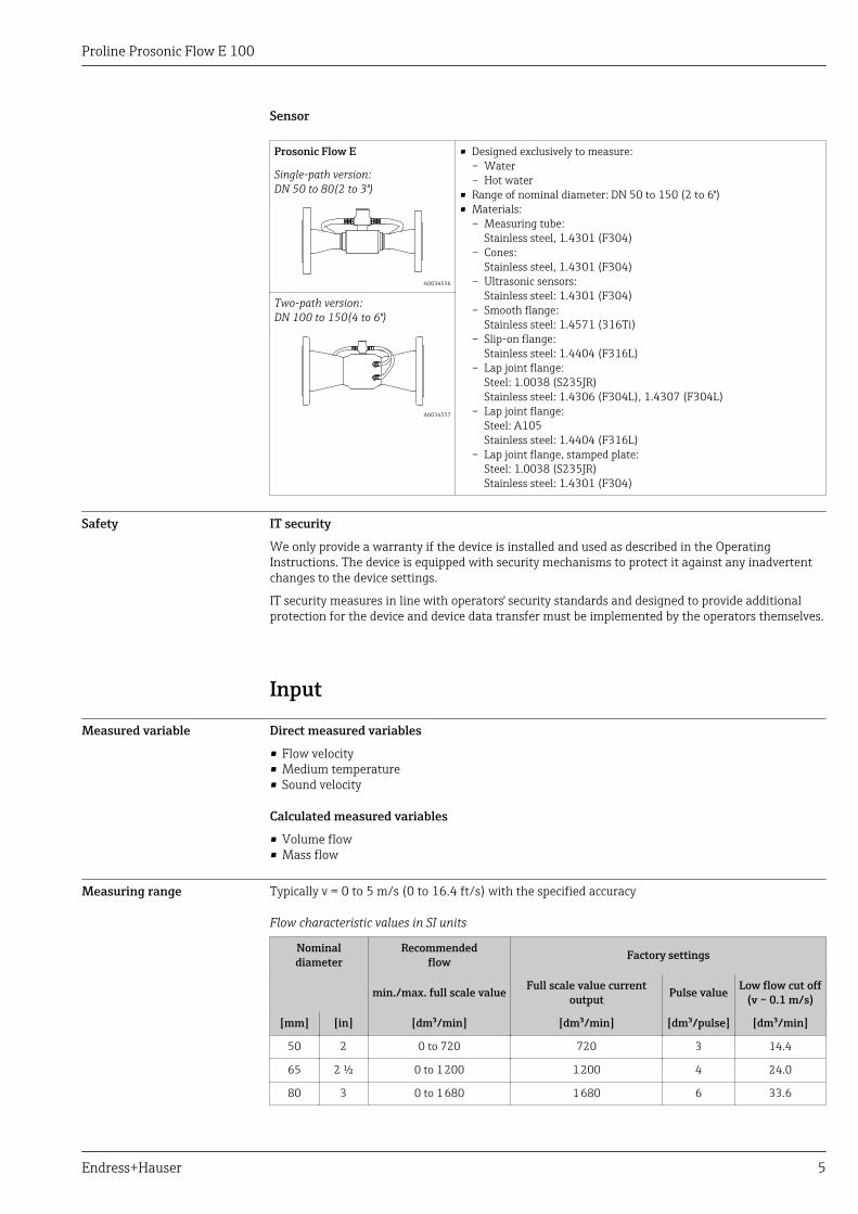
Lap joint flange, stamped plate
L
D
C
A B
A0015457
Lap joint flange, stamped plate following EN 1092-1 (DIN 2501): PN 101.0038 (S235JR): order code for "Process connection", option D211.4301 (F304): order code for "Process connection", option D23
DN[mm]
A[mm]
B[mm]
C[mm]
D[mm]
L[mm]
50 165 125 18.5 4 × 17.5 300 1)
65 185 145 20.0 4 × 17.5 300 1)
80 200 160 23.5 8 × 17.5 350 2)
100 220 180 24.5 8 × 17.5 350 2)
150 285 240 25.0 8 × 21.5 500 2)
1) Tolerance: 0/-2 mm2) Tolerance: 0/-3 mm
Dimensions in US units Compact version
Order code for "Housing", options A "Compact, aluminum, coated"
A
B C
G
D
L
E
F
K
M
A0033784
DN[in]
A[in]
B[in]
C[in]
D[in]
E 1)
[in]F 1)
[in]G
[in]K 2)
[in]L
[in]M
[in]
2 5.35 3.23 2.13 3.25 9.19 12.4 5.35 1.38 3) 2.42
2 ½ 5.35 3.23 2.13 3.64 9.37 13.0 5.35 1.72 3) 2.80
3 5.35 3.23 2.13 3.94 9.49 13.4 5.35 1.94 3) 3.01

Proline Prosonic Flow E 100
26 Endress+Hauser
DN[in]
A[in]
B[in]
C[in]
D[in]
E 1)
[in]F 1)
[in]G
[in]K 2)
[in]L
[in]M
[in]
4 5.35 3.23 2.13 4.63 10.2 14.8 5.35 2.95 3) 4.33
6 5.35 3.23 2.13 5.91 10.9 16.8 5.35 4.34 3) 5.71
1) When using a display (order code for "Display; Operation", option B): Values +1.1 in2) Tolerance: ±0.08 in3) Dependent on respective process connection
Flange connections
Fixed flange
C
D
A B E
L
A0015621
Slip-on flange following ASME B16.5: Class 1501.4404 (F316L): Order code for "Process connection", option A1S
DN[in]
A[in]
B[in]
C[in]
D[in]
E 1)
[in]L
[in]
2 6.00 4.75 4 × 0.75 1.00 2.22 11.8 2)
3 7.50 6.00 4 × 0.75 1.19 3.33 13.8 3)
4 9.00 7.50 8 × 0.75 1.31 4.34 13.8 3)
6 11.0 9.50 8 × 0.88 1.56 6.47 19.7 3)
1) Tolerance: ±0.08 in2) Tolerance: 0/-0.08 in3) Tolerance: 0/-0.12 in
Lap joint flange
L
D
C
A B
A0015457
Proline Prosonic Flow E 100
Endress+Hauser 27
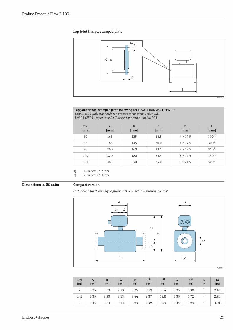
Lap joint flange following ASME B16.5: Class 150A105: order code for "Process connection", option A121.4404 (F316L): order code for "Process connection", option A14
DN[in]
A[in]
B[in]
C[in]
D[in]
L[in]
2 6.00 4.75 1.00 4 × 0.75 11.8 1)
3 7.50 6.00 1.19 4 × 0.75 13.8 2)
4 9.00 7.50 1.31 8 × 0.75 13.8 2)
6 11.0 9.50 1.56 8 × 0.88 19.7 2)
1) Tolerance: 0/-0.08 in2) Tolerance: 0/-0.12 in
Weight Weight in SI units
Compact version
Order code for "Housing", option A "Compact, aluminum, coated"
Nominal diameter[mm]
Version Fixed flange Lap joint flange Lap joint flange, stampedplate
EN 1092-1(DIN 2501) 1)
[kg]
ASME B16.5 2)
[kg]EN 1092-1
(DIN 2501) 3)
[kg]
ASME B16.5 2)
[kg]EN 1092-1 (DIN 2501) 4)
[kg]
50 Single-path 9.15 8.00 8.90 8.10 7.20
65 Single-path 10.8 – 10.7 – 8.10
80 Single-path 12.2 12.8 12.2 12.9 8.80
100 Two-path 16.1 18.1 16.0 17.9 11.2
150 Two-path 25.4 26.4 22.0 26.2 17.5
1) Pressure rating PN 40 (DN 50), PN 16 (DN 65 to 150)2) Pressure rating, class 1503) Pressure rating PN 10/164) Pressure rating PN 10
Weight in US units
Compact version
Order code for "Housing", option A "Compact, aluminum, coated"
Nominal diameter[in]
Version Fixed flange Lap joint flange
ASME B16.5 1)
[lbs]ASME B16.5 1)
[lbs]
2 Single-path 17.6 17.9
3 Single-path 28.2 28.5
4 Two-path 39.9 39.5
6 Two-path 58.2 57.7
1) Pressure rating, class 150
Materials Transmitter housing
• Order code for "Housing", option A "Compact, aluminum coated":Aluminum, AlSi10Mg, coated
• Window material for optional local display (→ 29):Order code for "Display; Operation", option B: glass
Proline Prosonic Flow E 100
28 Endress+Hauser
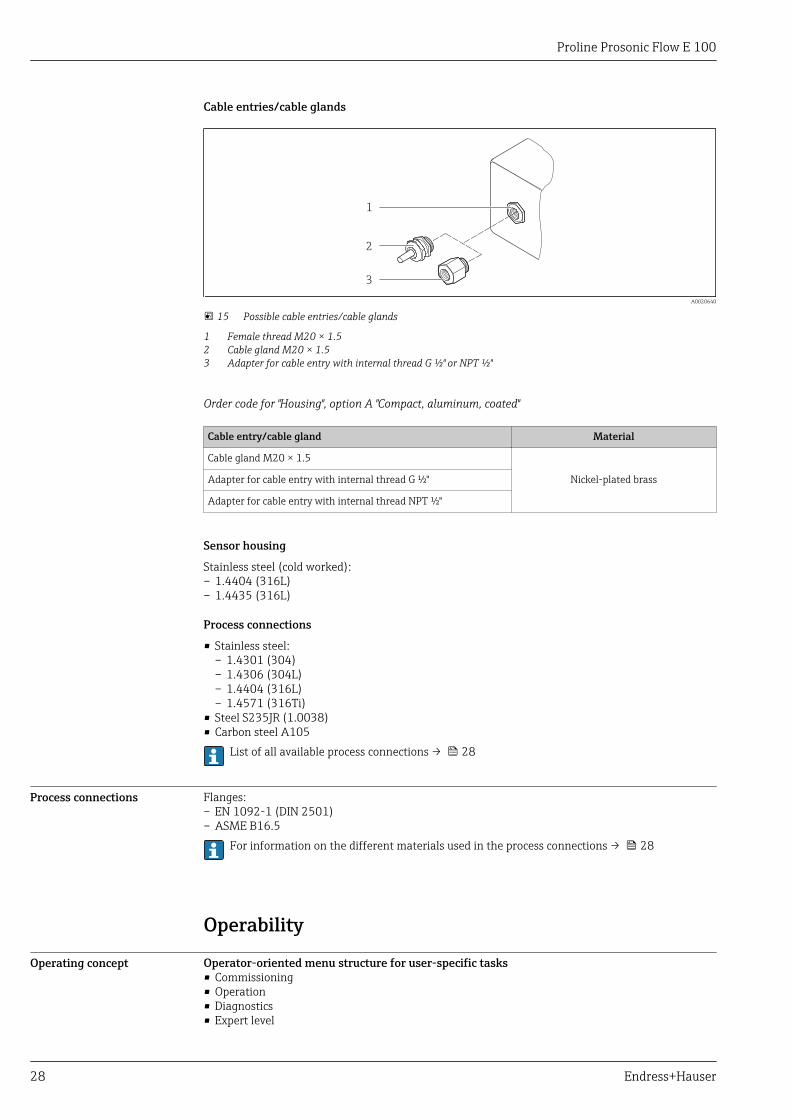
Cable entries/cable glands
1
2
3
A0020640
15 Possible cable entries/cable glands
1 Female thread M20 × 1.52 Cable gland M20 × 1.53 Adapter for cable entry with internal thread G ½" or NPT ½"
Order code for "Housing", option A "Compact, aluminum, coated"
Cable entry/cable gland Material
Cable gland M20 × 1.5
Nickel-plated brassAdapter for cable entry with internal thread G ½"
Adapter for cable entry with internal thread NPT ½"
Sensor housing
Stainless steel (cold worked):– 1.4404 (316L)– 1.4435 (316L)
Process connections
• Stainless steel:– 1.4301 (304)– 1.4306 (304L)– 1.4404 (316L)– 1.4571 (316Ti)
• Steel S235JR (1.0038)• Carbon steel A105
List of all available process connections → 28
Process connections Flanges:– EN 1092-1 (DIN 2501)– ASME B16.5
For information on the different materials used in the process connections → 28
Operability
Operating concept Operator-oriented menu structure for user-specific tasks• Commissioning• Operation• Diagnostics• Expert level

Proline Prosonic Flow E 100
Endress+Hauser 29
Quick and safe commissioning• Individual menus for applications• Menu guidance with brief explanations of the individual parameter functionsReliable operation• Operation in the following languages:
– Via "FieldCare", "DeviceCare" operating tool:English, German, French, Spanish, Italian, Chinese, Japanese
– Via integrated Web browser:English, German, French, Spanish, Italian, Dutch, Portuguese, Polish, Russian, Turkish, Chinese,Japanese, Bahasa (Indonesian), Vietnamese, Czech, Swedish, Korean
• Uniform operating philosophy applied to operating tools and Web browser• If replacing the electronic module, transfer the device configuration via the plug-in memory
(HistoROM DAT) which contains the process and measuring device data and the event logbook. Noneed to reconfigure.
Efficient diagnostics increase measurement availability• Troubleshooting measures can be called up via the operating tools• Diverse simulation options• Status indicated by several light emitting diodes (LEDs) on the electronic module in the housing
compartment
Local display The local display is only available with the following device order code:Order code for "Display; operation", option B: 4-line; illuminated, via communicationDisplay element• 4-line liquid crystal display with 16 characters per line.• White background lighting; switches to red in event of device errors.• Format for displaying measured variables and status variables can be individually configured.• Permitted ambient temperature for the display: –20 to +60 °C (–4 to +140 °F). The readability of
the display may be impaired at temperatures outside the temperature range.
Remote operation Via HART protocol
1 2 3 5
74 6
A0016948
16 Options for remote operation via HART protocol
1 Control system (e.g. PLC)2 Field Communicator 4753 Computer with operating tool (e.g. FieldCare, AMS Device Manager, SIMATIC PDM)4 Commubox FXA195 (USB)5 Field Xpert SFX350 or SFX3706 VIATOR Bluetooth modem with connecting cable7 Transmitter
Service interface Via service interface (CDI-RJ45)

Proline Prosonic Flow E 100
30 Endress+Hauser
HART
1
2
3
A0016926
17 Connection for the order code for "Output", option B: 4-20 mA HART, pulse/frequency/switch output
1 Service interface (CDI -RJ45) of the measuring device with access to the integrated Web server2 Computer with Web browser (e.g. Internet Explorer) for accessing the integrated device Web server or with
"FieldCare" operating tool with COM DTM "CDI Communication TCP/IP"3 Standard Ethernet connecting cable with RJ45 plug
Certificates and approvals
CE mark The measuring system is in conformity with the statutory requirements of the applicable EUDirectives. These are listed in the corresponding EU Declaration of Conformity along with thestandards applied.
Endress+Hauser confirms successful testing of the device by affixing to it the CE mark.
C-Tick symbol The measuring system meets the EMC requirements of the "Australian Communications and MediaAuthority (ACMA)".
HART certification HART interface
The measuring device is certified and registered by the FieldComm Group. The measuring systemmeets all the requirements of the following specifications:• Certified according to HART 7.5• The device can also be operated with certified devices of other manufacturers (interoperability)
Pressure EquipmentDirective
The devices can be ordered with or without a PED approval. If a device with a PED approval isrequired, this must be explicitly stated in the order.
• With the identification PED/G1/x (x = category) on the sensor nameplate, Endress+Hauserconfirms conformity with the "Essential Safety Requirements" specified in Appendix I of thePressure Equipment Directive 2014/68/EC.
• Devices bearing this marking (PED) are suitable for the following types of medium:Media in Group 1 and 2 with a vapor pressure greater than, or smaller and equalto0.5 bar (7.3 psi)
• Devices not bearing this marking (PED) are designed and manufactured according to goodengineering practice. They meet the requirements of Art. 4, Par. 3 of the Pressure EquipmentDirective 2014/68/EU. The range of application is indicated in tables 6 to 9 in Annex II of thePressure Equipment Directive 2014/68/EC.

Proline Prosonic Flow E 100
Endress+Hauser 31
Other standards andguidelines
• EN 60529Degrees of protection provided by enclosures (IP code)
• EN 61010-1Safety requirements for electrical equipment for measurement, control and laboratory use -general requirements
• IEC/EN 61326Emission in accordance with Class A requirements. Electromagnetic compatibility (EMCrequirements).
• NAMUR NE 21Electromagnetic compatibility (EMC) of industrial process and laboratory control equipment
• NAMUR NE 32Data retention in the event of a power failure in field and control instruments withmicroprocessors
• NAMUR NE 43Standardization of the signal level for the breakdown information of digital transmitters withanalog output signal.
• NAMUR NE 53Software of field devices and signal-processing devices with digital electronics
• NAMUR NE 80The application of the pressure equipment directive to process control devices
• NAMUR NE 105Specifications for integrating fieldbus devices in engineering tools for field devices
• NAMUR NE 107Self-monitoring and diagnosis of field devices
• NAMUR NE 131Requirements for field devices for standard applications
Ordering informationDetailed ordering information is available as follows:• In the Product Configurator on the Endress+Hauser website: www.endress.com -> Click "Corporate"
-> Select your country -> Click "Products" -> Select the product using the filters and search field ->Open product page -> The "Configure" button to the right of the product image opens the ProductConfigurator.
• From your Endress+Hauser Sales Center:www.addresses.endress.comProduct Configurator - the tool for individual product configuration• Up-to-the-minute configuration data• Depending on the device: Direct input of measuring point-specific information such as
measuring range or operating language• Automatic verification of exclusion criteria• Automatic creation of the order code and its breakdown in PDF or Excel output format• Ability to order directly in the Endress+Hauser Online Shop
Application packagesMany different application packages are available to enhance the functionality of the device. Suchpackages might be needed to address safety aspects or specific application requirements.
The application packages can be ordered with the device or subsequently from Endress+Hauser.Detailed information on the order code in question is available from your local Endress+Hauser salescenter or on the product page of the Endress+Hauser website: www.endress.com.
Proline Prosonic Flow E 100
32 Endress+Hauser
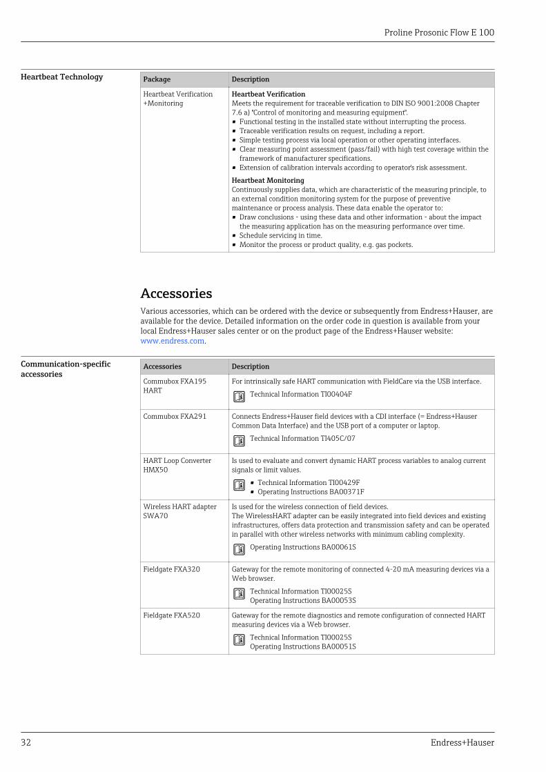
Heartbeat Technology Package Description
Heartbeat Verification+Monitoring
Heartbeat VerificationMeets the requirement for traceable verification to DIN ISO 9001:2008 Chapter7.6 a) "Control of monitoring and measuring equipment".• Functional testing in the installed state without interrupting the process.• Traceable verification results on request, including a report.• Simple testing process via local operation or other operating interfaces.• Clear measuring point assessment (pass/fail) with high test coverage within the
framework of manufacturer specifications.• Extension of calibration intervals according to operator's risk assessment.
Heartbeat MonitoringContinuously supplies data, which are characteristic of the measuring principle, toan external condition monitoring system for the purpose of preventivemaintenance or process analysis. These data enable the operator to:• Draw conclusions - using these data and other information - about the impact
the measuring application has on the measuring performance over time.• Schedule servicing in time.• Monitor the process or product quality, e.g. gas pockets.
AccessoriesVarious accessories, which can be ordered with the device or subsequently from Endress+Hauser, areavailable for the device. Detailed information on the order code in question is available from yourlocal Endress+Hauser sales center or on the product page of the Endress+Hauser website:www.endress.com.
Communication-specificaccessories
Accessories Description
Commubox FXA195HART
For intrinsically safe HART communication with FieldCare via the USB interface.
Technical Information TI00404F
Commubox FXA291 Connects Endress+Hauser field devices with a CDI interface (= Endress+HauserCommon Data Interface) and the USB port of a computer or laptop.
Technical Information TI405C/07
HART Loop ConverterHMX50
Is used to evaluate and convert dynamic HART process variables to analog currentsignals or limit values.
• Technical Information TI00429F• Operating Instructions BA00371F
Wireless HART adapterSWA70
Is used for the wireless connection of field devices.The WirelessHART adapter can be easily integrated into field devices and existinginfrastructures, offers data protection and transmission safety and can be operatedin parallel with other wireless networks with minimum cabling complexity.
Operating Instructions BA00061S
Fieldgate FXA320 Gateway for the remote monitoring of connected 4-20 mA measuring devices via aWeb browser.
Technical Information TI00025SOperating Instructions BA00053S
Fieldgate FXA520 Gateway for the remote diagnostics and remote configuration of connected HARTmeasuring devices via a Web browser.
Technical Information TI00025SOperating Instructions BA00051S

Proline Prosonic Flow E 100
Endress+Hauser 33
Field Xpert SFX350 Field Xpert SFX350 is a mobile computer for commissioning and maintenance. Itenables efficient device configuration and diagnostics for HART and FOUNDATIONFieldbus devices and can be used in non-hazardous areas.
Operating Instructions BA01202S
Field Xpert SFX370 Field Xpert SFX370 is a mobile computer for commissioning and maintenance. Itenables efficient device configuration and diagnostics for HART and FOUNDATIONFieldbus devices and can be used in the non-hazardous area and in the hazardousarea.
Operating Instructions BA01202S
Service-specific accessories Accessories Description
Applicator Software for selecting and sizing Endress+Hauser measuring devices:• Choice of measuring devices for industrial requirements• Calculation of all the necessary data for identifying the optimum flowmeter: e.g.
nominal diameter, pressure loss, flow velocity and accuracy.• Graphic illustration of the calculation results• Determination of the partial order code, administration, documentation and
access to all project-related data and parameters over the entire life cycle of aproject.
Applicator is available:• Via the Internet: https://portal.endress.com/webapp/applicator• As a downloadable DVD for local PC installation.
W@M W@M Life Cycle ManagementImproved productivity with information at your fingertips. Data relevant to a plantand its components is generated from the first stages of planning and during theasset’s complete life cycle.W@M Life Cycle Management is an open and flexible information platform withonline and on-site tools. Instant access for your staff to current, in-depth datashortens your plant’s engineering time, speeds up procurement processes andincreases plant uptime.Combined with the right services, W@M Life Cycle Management boostsproductivity in every phase. For more information, visitwww.endress.com/lifecyclemanagement
FieldCare FDT-based plant asset management tool from Endress+Hauser.It can configure all smart field units in your system and helps you manage them. Byusing the status information, it is also a simple but effective way of checking theirstatus and condition.
Operating Instructions BA00027S and BA00059S
DeviceCare Tool to connect and configure Endress+Hauser field devices.
Innovation brochure IN01047S
System components Accessories Description
Memograph M graphicdata manager
The Memograph M graphic data manager provides information on all the relevantmeasured variables. Measured values are recorded correctly, limit values aremonitored and measuring points analyzed. The data are stored in the 256 MBinternal memory and also on a SD card or USB stick.
• Technical Information TI00133R• Operating Instructions BA00247R
Supplementary documentationFor an overview of the scope of the associated Technical Documentation, refer to the following:• The W@M Device Viewer : Enter the serial number from the nameplate
(www.endress.com/deviceviewer)• The Endress+Hauser Operations App: Enter the serial number from the nameplate or scan the
2-D matrix code (QR code) on the nameplate.

Proline Prosonic Flow E 100
34 Endress+Hauser
Standard documentation Brief Operating Instructions
Brief Operating Instructions for the sensor
Measuring device Documentation code
Proline Prosonic Flow E KA01329D
Brief Operating Instructions for transmitter
Measuring device Documentation code
HART
Proline 100 KA01330D
Operating Instructions
Measuring device Documentation code
HART
Prosonic Flow E 100 BA01769D
Description of Device Parameters
Measuring device Documentation code
HART
Prosonic Flow 100 GP01124D
Supplementary device-dependent documentation
Special documentation
Contents Documentation code
Information on the Pressure EquipmentDirective
SD01614D
RFID TAG SD01565D
Contents Documentation code
HART
Heartbeat Technology SD02079D
Installation Instructions
Contents Comment
Installation instructions for spare part sets and accessories Documentation code: specified for each individual accessory .
Registered trademarksHART®Registered trademark of the FieldComm Group, Austin, Texas, USAMicrosoft®Registered trademark of the Microsoft Corporation, Redmond, Washington, USA


www.addresses.endress.com