Embed Size (px)
Citation preview
8/4/2019 Project HEXAGON Overview
http://slidepdf.com/reader/full/project-hexagon-overview 1/125
NRO APPROVED FORRELEASE 17 September 2011
8/4/2019 Project HEXAGON Overview
http://slidepdf.com/reader/full/project-hexagon-overview 2/125
T O P S E C R E T /H BIF003W/2-093942-77
HEXAGON CY31 DECEMBER 197772 SHEETS
P R O J EC T H EX A G O N
OVERVIEW
C L A S S I F I E D B YVEMAN 1XEM PT F R O M GEN ER AL D EC LASSI FI C AT IONS C HE D UL E O F E 0 11662 , E X E MP TI O N C A TE G O RY 58 . 12)
AU T OM AT I C ALLY D EC LASSI FI ED ON : I M POSSI BLE T O D ET ER M I N E
NA TI O NA L S E C URI TY I NFO RMA TI O NUNAUTHORIZED DISCLOSURE SUBJECT TO CRIMINAL SANCTIONS I
W AR d I N G N OT I C ES E NS I T IVE I NTE L L I G E NC E S O URC E S A ND ME THO D S I NVO L VE D
HANDLEVEMANCONTROL SYSTEM ONLY
T O P S E C R E T /H
NRO APPROVED FORRELEASE 17 September 2011

8/4/2019 Project HEXAGON Overview
http://slidepdf.com/reader/full/project-hexagon-overview 3/125
NRO APPROVED FORRELEASE 17 September 2011
8/4/2019 Project HEXAGON Overview
http://slidepdf.com/reader/full/project-hexagon-overview 4/125
TO P S E CRE T/H
H E X A G O N V E H IC L E O N O R B I T
BIF003VV/2-093942-77 3OP SECRET/H
NRO APPROVED FORRELEASE 17 September 2011
8/4/2019 Project HEXAGON Overview
http://slidepdf.com/reader/full/project-hexagon-overview 5/125
NRO APPROVED FORRELEASE 17 September 2011

8/4/2019 Project HEXAGON Overview
http://slidepdf.com/reader/full/project-hexagon-overview 6/125
NRO APPROVED FORRELEASE 17 September 2011
8/4/2019 Project HEXAGON Overview
http://slidepdf.com/reader/full/project-hexagon-overview 7/125
T O P S E C R E T /H
A S SO C IA T E C O N T R A C T O R Sn11 1nO
Project HEXAGON is a team effort consisting of nine major contractors throughout the United States. These contractors
provide a coordinated effort by using Interface Control Documents as binding technical agreement on responsibilities and
performance of their respective equipments. The project HEXAGON team consists of:
Search/Surveillance (Stereo Panoramic)
Two Camera Assembly — Perkin-Elmer, DanburyFilm supply and take-up units — Perkin-Elmer, DanburyShroud, Mid and Forward Section structure — Lockheed, SunnyvaleReentry vehicles (Mark 8) — McDonnell Douglas, St. LouisFilm — Eastman Kodak, Rochester
M apping and Geodesy SystemStellar and terrain cameras — Itek, BurlingtonReentry vehicle (Mark V) — General Electric, PhiladelphiaStructure — Lockheed, SunnyvaleFilm — Eastman Kodak, Rochester
Satellite Control Section
Telemetry, power, and pyros — Lockheed, SunnyvaleCommand system — General Electric, UticaAttitude control and orbit adjust — Lockheed, SunnyvaleStructure and booster adapter — Lockheed, Sunnyvale
B ooster Vehicle — Titan IHD
Stage 0 solid propellant — United Technologies Chemical System Division, SunnyvaleStage I and II liquid propellant — Martin Marietta Corporation, Denver
The photographs were taken via the search and surveillance camera and magnified 40 times.
6 T O P S E C R E T /H BIF003W/2-093942-77
NRO APPROVED FORRELEASE 17 September 2011
8/4/2019 Project HEXAGON Overview
http://slidepdf.com/reader/full/project-hexagon-overview 8/125
NRO APPROVED FORRELEASE 17 September 2011
NRO APPROVED FOR

8/4/2019 Project HEXAGON Overview
http://slidepdf.com/reader/full/project-hexagon-overview 9/125
T O P S E C R E T /H
O P E R A T I O N S
i
T O P S E C R E T /H1F003W/2-093942-77
NRO APPROVED FORRELEASE 17 September 2011
NRO APPROVED FOR
8/4/2019 Project HEXAGON Overview
http://slidepdf.com/reader/full/project-hexagon-overview 10/125
T O P S E C R E T /H
A E R O S P A C E V E H IC L E
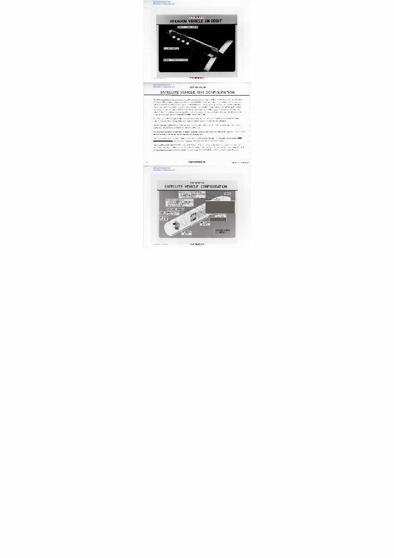
The HEXAGON Satellite Vehicle is launched by the Titan HID Booster Vehicle. When
mated together, the entire assembly is termed the Aerospace Vehicle.
The Aerospace Vehicle is launched from Space Launch Complex -4 East, Vandenberg
Air Force Base. The Solid Rocket Motor, Stage I and Stage II are stacked at the launch
site and functionally tested. The complete SV including the shroud is mated to the
booster vehicle fourteen (14) days prior to launch. The Aerospace Vehicle is then func-
tionally checked and all propellants and gases are loaded.
The booster vehicle can place 24,800 pounds into an 82 x 144 nm (perigee x apogee) orbit
with an inclination (-97 degrees) that provides the nearly sun synchronous condition
needed for long life missions.
IL
10 O P S E C R E T /H
IF003W/2-093942-77
NRO APPROVED FORRELEASE 17 September 2011
NRO APPROVED FOR

8/4/2019 Project HEXAGON Overview
http://slidepdf.com/reader/full/project-hexagon-overview 11/125
A E R O S P A C E V E H IC L E
NRO APPROVED FORRELEASE 17 September 2011
NRO APPROVED FOR
8/4/2019 Project HEXAGON Overview
http://slidepdf.com/reader/full/project-hexagon-overview 12/125
T O P S E C R E T /H
T IT A N IIID B O O S T E R V E H ICLE
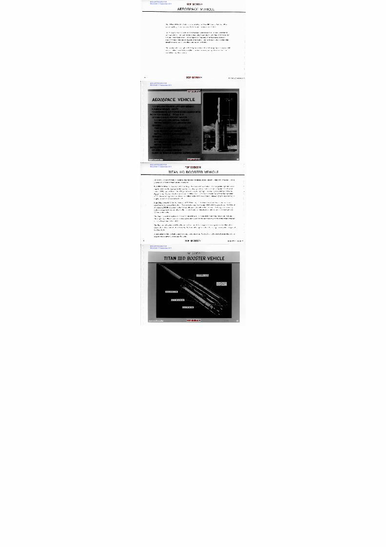
The Titan HID booster vehicle is a three-stage booster consisting of the standard liquid core for Stages I and II
plus two solid rocket motors (SRMs) as Stage 0.
Each SRM is 10 feet in diameter and 85 feet long. It consists of five identical interchangeable segments, a six-
degree canted nozzle, a gas generator type igniter, staging rockets, and an externally mounted thrust vector
control (TVC) injectant tank. The TVC provides steering during Stage 0 burn by injecting nitrogen tetroxide
(N2
04) through 24 proportional valves around the SRM nozzle. Jettison is provided by pyrotechnic separation
of the interconnecting structure between each SRM and the Titan core vehicle, followed by ignition of four solid
staging rockets at each end of each SRM.
Stage I liquid core is 10 feet in diameter and 71.5 feet long. It is aluminum skin-stringer construction with
propellant tanks arranged in tandem. The two turbo pump feed Aerojet LR87-AJ-11 engines burn a 50-50 blend
of hydrazine/UDMH (Aerozine) as the fuel and nitrogen textroxide as the oxidizer. Each engine subassembly
contains a regeneratively cooled gimballed thrust chamber combined with an ablative skirt extension giving a
15:1 expansion ratio.
The Stage II propulsion system is similar to that of Stage I. It is also 10 ft in diameter but only 31 feet long.
The single engine thrust chamber is also regeneratively cooled and has an ablative skirt extension that providesan overall expansion ratio of 49:1.
The flight control system stabilizes the vehicle from launch to SV separation in response to (1) attitude data,
(2) rate data, (3) command data — issued by flight control computer and/or the radio guidance system via ground
tracking station.
Electrical power for the flight control system, instrumentation, flight safety, and electrical sequencing system
is provided via silver-zinc primary batteries.
r ir .
rL
U
T O P S E C R E T /H2 BIF003W/2-093942-77
NRO APPROVED FORRELEASE 17 September 2011
NRO APPROVED FOR

8/4/2019 Project HEXAGON Overview
http://slidepdf.com/reader/full/project-hexagon-overview 13/125
A N B I D B O O S T E R V E H I C L E
NRO APPROVED FORRELEASE 17 September 2011
NRO APPROVED FOR
8/4/2019 Project HEXAGON Overview
http://slidepdf.com/reader/full/project-hexagon-overview 14/125
T O P S E C R E T /H
O P E R A T IO N A L EV E N T S
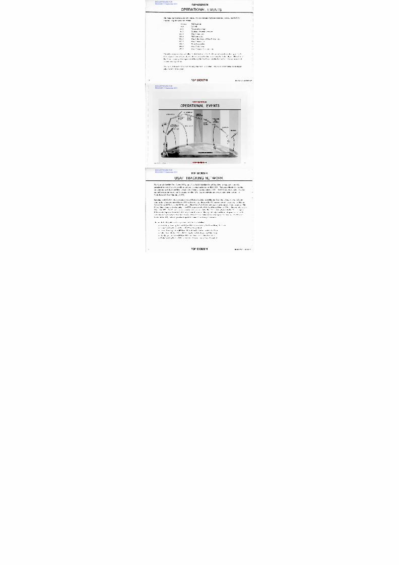
The major operational events are launch, orbit maintenance/payload operations, and RV recovery/SV
deboost. Sequence of launch events:
0.0 secRM Ignition
0.2ift-off
40.0ransonic passage
54.0aximum dynamic pressure
113 .9ore I start burn
125.3RM separation
262.0ore I shutdown and Core H start burn
262.7ore I separation
276.0hroud separation
460.6ore II shutdown
472.6ore II separation (injection)
The solar arrays are deployed after SV stabilization on Rev 1 with payload operations starting on Rev 5.
Orbit adjusts to correct period, altitude and perigee location occur every two to four days. All control of
the SV and telemetry data is processed through the Air Force Satellite Control Facilities and associated
remote tracking stations.
The SV is pitched down to a specified angle for each RV ejection. The SV is deboosted for ocean impact
after the last RV is ejected.
C
T O P S E C R E T /H4 BIF003W/2-093942-77
NRO APPROVED FORRELEASE 17 September 2011
NRO APPROVED FOR

8/4/2019 Project HEXAGON Overview
http://slidepdf.com/reader/full/project-hexagon-overview 15/125
TO P S E CRE T/H5IF003W/2-093942-77
TOP SECRET/H
O P E R A T IO N A L EV E N T S
S H R O U DEJECT
S V S E P A R A T I O N
Cftn,IE N S O R-" " O P E R A T I O NSOLARARRAYDEPLOY
TITAN II I DS R M B U R N O U TO R E I N T R Y
e•n
J E T T I S O N•••
I• %1
ir
CORE I I BURN
C O M M A N DA N D
C O N T R O L
ORBITA DJ U ST
R E C O V E R Y
D E B O O S T
5
6
J
RELEASE 17 September 2011
NRO APPROVED FOR

8/4/2019 Project HEXAGON Overview
http://slidepdf.com/reader/full/project-hexagon-overview 16/125
T O P S E C R E T /H
U S A F T R A C KIN G N E T W O R K
The Sunnyvale Satellite Test Center (STC), part of the SAMSO Satellite Control Facilities, is organized to provide
operational control of on-orbit satellites and does this function for project HEXAGON. The center directs the trackingand commanding of these satellites through a net of remote tracking stations (RTS). The STC also coordinates the aerial
and surface recovery operations for reentry vehicles (RV). Launch activities are a coordinated effort between the
V andenberg AFB Test Wing and the STC.
Servicing the HEXAGON vehicle requires skin and beacon tracking, recording and displaying telemetry data, and com-
manding that often needs more than one RTS each revolution. Because the STC supports several programs, the Mission
Control Center (MCC) within the STC is used to direct the effort of each tracking station in support of each program. The
SV real time telemetry data incoming to the RTS are processed and displayed in real time via 1200 bit lines or relay satel-
lites to the STC. The SV real time and recorded data are recorded at the RTS for later playback to the STC. Complete
RTS recorded tapes are flown to the STC as permanent records. Display and analysis of these data provides SV health
and status information to the Technical Advisor (TA) staff on a continuous basis throughout the mission. The TA staff,
located at the STC, includes operational specialist teams for each major contractor.
The remote tracking stations acronyms and locations are as follows:
Vandenberg Tracking Station (VTS) or COOK at Vandenberg Air Force Base, California
Guam Tracking Station (GTS) or GUAM on Guam Island
Hawaii Tracking Station (H TS) or HUL A at Kaeha Point on the island of O ahu
Indian Ocean Station (I0S) or INDI in Seychelles Island group on Mahe' Island
New Hampshire Station (NHS) or BOSS near New Boston, New Hampshire
Thule Tracking Station (TTS) or POGO at Thule Air Force Base, Greenland
1 6 T O P S E C R E T /H BIF003W/2-093942-77
RELEASE 17 September 2011
NRO APPROVED FOR

8/4/2019 Project HEXAGON Overview
http://slidepdf.com/reader/full/project-hexagon-overview 17/125
U S A F T R A C KIN G N E T W O R K
17 .O P S E CRE T/HIF003VV/2-093942-77
TO P S E CRE T/H
RELEASE 17 September 2011
NRO APPROVED FORRELEASE S b
8/4/2019 Project HEXAGON Overview
http://slidepdf.com/reader/full/project-hexagon-overview 18/125
U
R EQ U IR EMEN TS D IA
C IA
N SA
S T A T E I C R S R E Q U I R E M E N T SR EQ U IR EMEN TS
A R M Y
N A V Y
AF
U
R EADOU T
> -
>U
I-Ul 1 2 c i
C O M M U N I C A T I O N
OT HE RE X A G O NI N TELL I GEN C EM A G E R YDA T A
FILMP RO CE S S ING ST C
W E A T H E RI N F O R M A T I O N
SO C( N R O )
ATASKING
O T H E RP R O G R A M S
TO P S E CRE T/H
HEXAG ON INTELLIG ENCE TASKING LOOP
1 8 BIF003W/2-093942-77OP SECRET/H
RELEASE 17 September 2011
NRO APPROVED FORRELEASE 17 S t b 2011
8/4/2019 Project HEXAGON Overview
http://slidepdf.com/reader/full/project-hexagon-overview 19/125
T O P S E C R E T /H
S E A R C H / S U R V E I L L A N C E C A M E R A S
11F003W/2-093942-77 T O P S E C R E T /H 19
RELEASE 17 September 2011
NRO APPROVED FORRELEASE 17 September 2011
8/4/2019 Project HEXAGON Overview
http://slidepdf.com/reader/full/project-hexagon-overview 20/125
T O P S E C R E T /H
S E A R C H /S U R V E IL LA N C E C A M E R A S
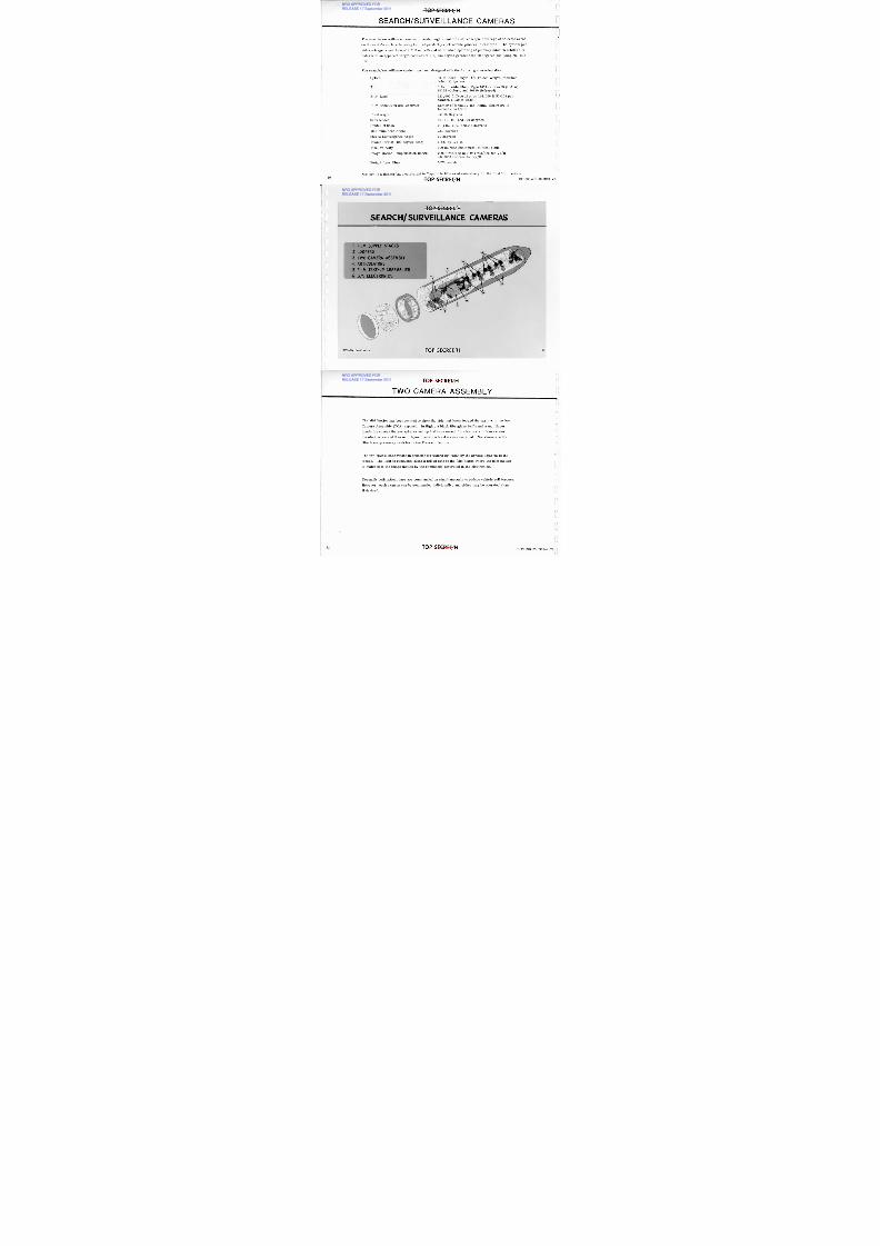
The search/surveillance cameras provide high-resolution stereoscopic coverage of selected areas
on the earth's surface by using two independently controllable panoramic cameras. The system pro-
vides a target resolution of 2.7 ft or better at nadir when operating at primary mission orbital alti-
tudes with an apparent target contrast of 2:1, sun angles greater than 30 degrees and using *S0-208
film.
The search/surveillance system has been designed with the following characteristics:
Optics0-in. focal length, f/3 Folded Wright (ModifiedSchmidt) System
Film.6-in. wide film — Type 141 4 or S0-208 (B & W),S0255 (C olor), and 50130 ( Infrared)
Film Load23,000 ft Type 1414 or 144,000 ft S0-208 percamera (1950 lb total)
Film Resolution (2:1 Contrast)enter of format 155 1/mm, elsewhere informat a 94 1/mm
Field Angle2. 85 Degrees
Scan Modes0, 60, 90, and 120 degrees
Center of Scan, ±15, ±30, and ±-45 degrees
M aximum Scan Angle60 degrees
Stereo Convergence Angle0 degrees
Frame format (120 degree scan)-in. by 125-in.
Film Velocity00 in. /sec (maximum) at focal plane
Image M otion Compensation Range.018 rad/sec to 0.054 rad/sec for Vx/H±0.0033 rad/sec for Vy/H
Weight (less film)375 pounds
*S0-208 is a thinner base equivalent to Type 1414 film used extensively for the first 13 missions.
L.//
20T O P S E C R E T /HIF003W/2-093942-77}
RELEASE 17 September 2011
NRO APPROVED FORRELEASE 17 September 2011
8/4/2019 Project HEXAGON Overview
http://slidepdf.com/reader/full/project-hexagon-overview 21/125
T O P S E C R E T /HIF003W/2-093942-77
10 FILM SUP PLY STACKS
Ir Z C O O P E R S
® T W O -C A M E R A A S S E M B L Y
* A R T I C U L A T O R S
; CD F ILM TAKE-UP ASSEM BLIES' CS /S E L E C T R O N I C S
lIMEMENW-T O P S E C R E T / H
S E A R C H / S U R V E IL L A N C E CA M E R A SNEM
RELEASE 17 September 2011
NRO APPROVED FORRELEASE 17 September 2011
8/4/2019 Project HEXAGON Overview
http://slidepdf.com/reader/full/project-hexagon-overview 22/125
T O P S E C R E T /H
T W O C A M E R A A S S E M B LY
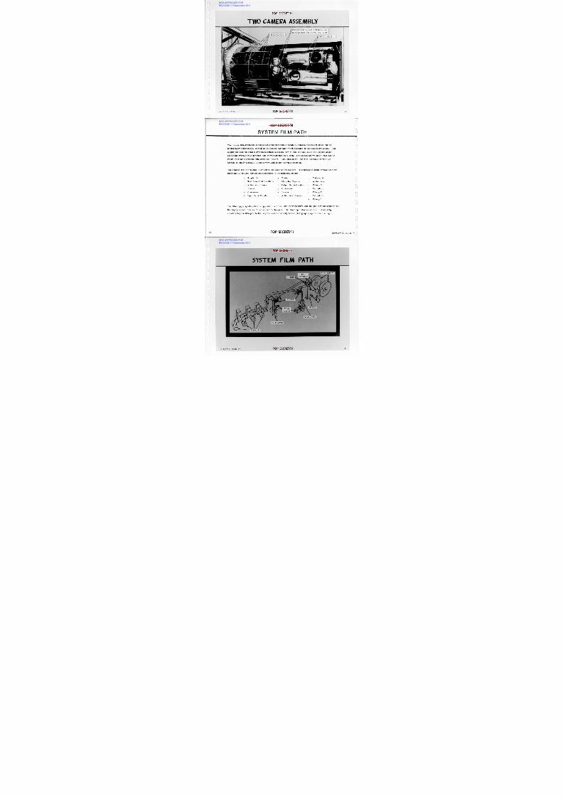
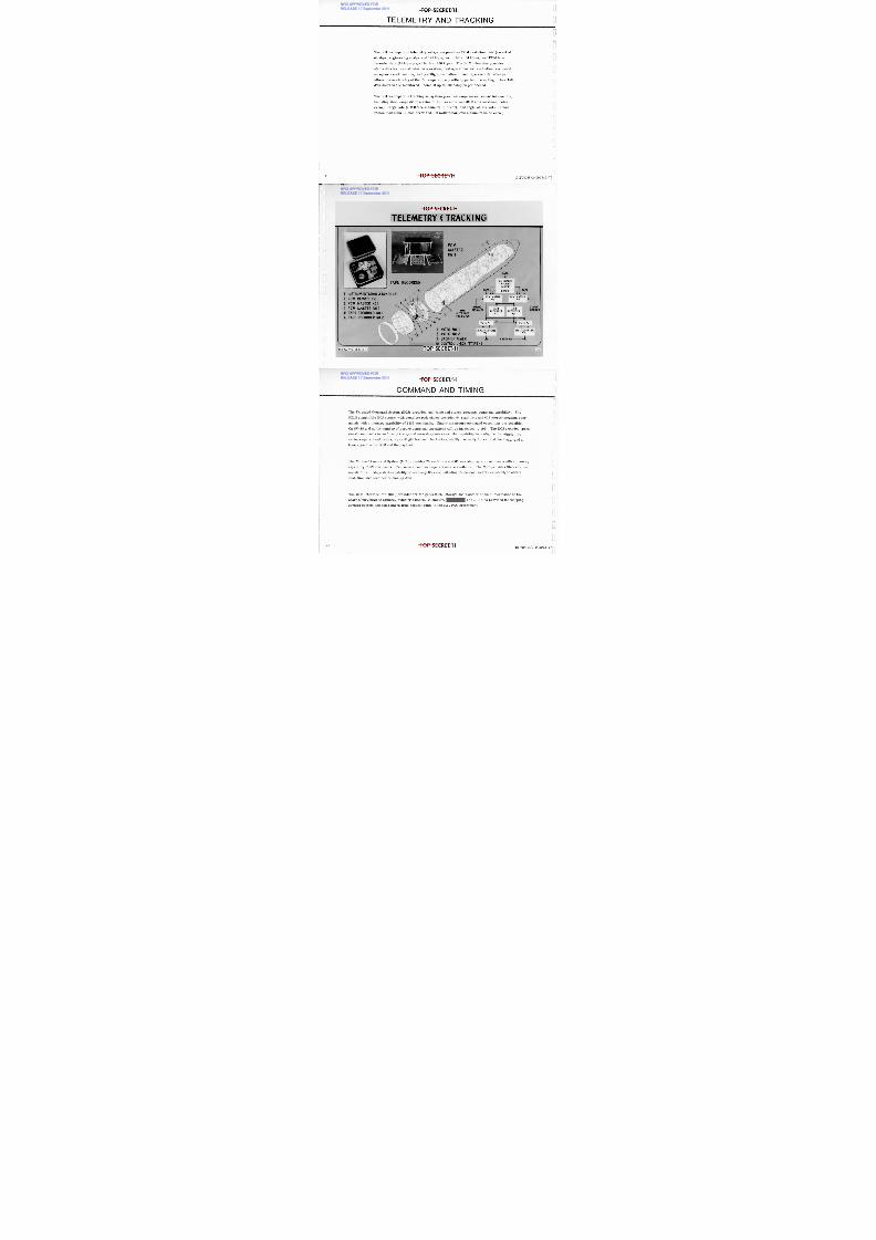
The Mid Section has been rotated to show the side that looks toward the earth with the two
Camera Assembly (TCA) exposed. In flight, a black fiberglass baffle and a multilayer
insulation covers the gas spheres and optical bars except for view ports. Doors cover
the electronics and then multilayer insulation blankets are installed. Not shown are the
film take-up reentry vehicles in the Forward Section.
The two optical bars rotate in opposite directions indicated by the arrows adjacent to thelenses. The light is conducted along a folded path to the film platen where the film motion
is matched to the image motion by the commands generated in the electronics.
Normally both optical bars are commanded on simultaneously to reduce vehicle roll torques.
However, each camera can be commanded individually, and either may be operated alone,
if desired.
22 T O P S E C R E T /HBIF003W/2-093942-77
1 1
RELEASE 17 September 2011
NRO APPROVED FORRELEASE 17 September 2011
8/4/2019 Project HEXAGON Overview
http://slidepdf.com/reader/full/project-hexagon-overview 23/125
TOP SECRET/H
TW O C A M E R A A S SE M B L Y41 •1 1 1 1 1 1 1 1 1 1 1 i . 4 1 0 1 1 m M I I M I N Inaw ,
E L E C T R O N I C S
P R ESSU R IZ ED N2
G A S S P H E R E S 3 4 L B S
I N C R E A S E D T O 6 8 L B S O N S V - I I & U P
O P T I C A L B A R S
BIF003W/2-093942-77 TO P S E CRE T/H
RELEASE 17 September 2011
NRO APPROVED FORRELEASE 17 September 2011
8/4/2019 Project HEXAGON Overview
http://slidepdf.com/reader/full/project-hexagon-overview 24/125
T O P S E C R E T /H
S Y S T E M F IL M P A T H
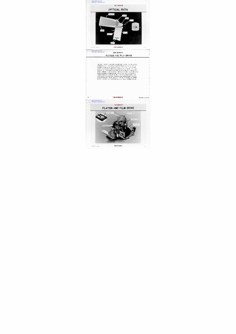
The coarse film transport includes all components that operate at nominally constant speed during
photography and recycle, as well as the looper carriage which operates at the recycle frequency. The
supply and take-up control system maintains a steady flow of film into and out of the loopers at pre-
cisely the average rate at which film moves through the platen. The loopers serve as an interface be-
tween the coarse and fine film transport system. Total film in the looper is constant but relative
lengths in supply and take-up sides vary with looper carriage position.
The control of film tracking is by active and passive articulators. The film path of the forward camera
functionally includes component assemblies in the following order:
a. Supply "B " g. Platen m. Take-up 4
b. Seal Door/Exit Vestibule h. Metering Capstan n. Articulator
c. Articulator Steerer i. Output Drive Capstan o. Takeup 3
d. Looper j. Crossover p. Articulator
Crossover k. Looper q. Takeup 2
Input Drive Capstan 1 . Articulator Steerer Articulator
Takeup 1
The film supply spools rotate in opposite directions, and the respective take-up spools rotate opposite to
the supply spools in order to reduce vehicle torques. The start-up disturbances are minimized by
accelerating the film path to the required coarse velocity before photographic operations are begun.
T O P S E C R E T /H4 BIF003W/2-093942-77
p
NRO APPROVED FORRELEASE 17 September 2011
8/4/2019 Project HEXAGON Overview
http://slidepdf.com/reader/full/project-hexagon-overview 25/125
TOP SECRET/H
SYSTEM FILM PA TH
BIF003W/2-093942-77 25T O P S E C R E V H
p
NRO APPROVED FORRELEASE 17 September 2011

8/4/2019 Project HEXAGON Overview
http://slidepdf.com/reader/full/project-hexagon-overview 26/125
T O P S E C R E T /H
O P T IC A L B A R A S S E M B L Y
The two cameras mounted in a frame make up a two-camera assembly with each
camera having a folded Wright optical system mounted in a rotating optical bar.
Structurally the bar consists of two rigid end bulkheads separated by a cylindrical
tube with housings and hollow shafts at each end on which bearings are mounted.
The platen end bulkhead is the member to which the optical components are refer-
enced. The optics consist of the corrector plate as the aperture, a folding flat
mirror, a concave primary mirror and a field group of refracting elements and a
filter. The optics wavefront errors spec values are shown as a fraction of the
wavelength. All values are root mean square (RMS).
T O P S E C R E T /H6
NRO APPROVED FORRELEASE 17 September 2011

8/4/2019 Project HEXAGON Overview
http://slidepdf.com/reader/full/project-hexagon-overview 27/125
F I R S T E LE M E N TS E C O N D E L E M E N TT H I R D E L E M E N T
F O U R T H E L E M E N TF iLTER
TOP SECRET/H
O P T IC A L B A R A S S E M B L Y
F IE L D G R O U P
A/28 R M S F O L D I N G F L A T4 0 R M S
E A C HSURFACE
A /5 0 R M S
1--
BIF003W/2-093942-77
C O R R E C T O R P L A TER I M A R Y M IR R O R
F I R S T S U R F A C E 7 1 3 0 R M S50 RMS
S E C O N D S U R F A C E A/6 0 R M S
TO P S E CRE T/H
NRO APPROVED FORRELEASE 17 September 2011
8/4/2019 Project HEXAGON Overview
http://slidepdf.com/reader/full/project-hexagon-overview 28/125
TO P S E C R E T / H
O P T IC A L P A T H
The optics for each camera are mounted in an optical bar (OB). The system is a
f/3 folded Wright. The aperture is formed by an aspheric corrector plate that cor-
rects for spherical aberration. Light entering the aperture is folded 90° by the folding
flat and reflected onto the primary mirror at the far end of the OB. The primary mir-
ror focuses the light back through the field group mounted in a center hole in the folding
flat. The field group includes four refracting elements and a filter. The refracting
elements provide correction for the field curvature and residual chromatic aberration
characteristics of optical systems using a concave primary mirror.
28 TOP SECRET /H BIF003W/2-093942-77
NRO APPROVED FORRELEASE 17 September 2011
8/4/2019 Project HEXAGON Overview
http://slidepdf.com/reader/full/project-hexagon-overview 29/125
O P T I C A L B A RCAMERA "A"
FOLDINGFLAT
FIELDG R O U P
SLITL E N G T H
P R I M A R YM I R R O R
C O R R E C T O R
PLATE
2 0 "APERTURE
1 / 1 0 RAD IAN
3.7 •
F I E L D O FV I E W
BIF003W/2-093942-77 O P S E CRE T/ H
9 •
TO P S E CRE T/ H
O PT ICAL PATH
NRO APPROVED FORRELEASE 17 September 2011
8/4/2019 Project HEXAGON Overview
http://slidepdf.com/reader/full/project-hexagon-overview 30/125
T O P S E C R E T /H
P L A T E N A N D F IL M D R IV E
The platen is mounted at the focal plane end of the optical bar (OB). The platen assembly
is mounted on the OB's inner housing to support the film in the camera focal plane, and
to rotate on its own bearings independently of the OB. While the OB is rotating continu-
ously on its end bearings, the platen assembly is free to oscillate through its 130-degree
operational arc. The fine film drive assembly encloses the outer end of the platen assem-
bly and is stationary. A twister assembly, included in the fine film drive assembly, accom-
modates the twisting of the film path at the interface between the stationary film drive
assembly and the oscillating platen assembly. The twister assembly consists of a twin
air-bar assembly and a housing that incorporates a manifold through which nitrogen gas
is supplied to the bars. The use of air bars in the twister, rather than rollers, permits
the film to translate along the length of the bars without damage as the film path twists.
30 T O P S E C R E T /H BIF003W/2-093942-77
[ 1
NRO APPROVED FORRELEASE 17 September 2011

8/4/2019 Project HEXAGON Overview
http://slidepdf.com/reader/full/project-hexagon-overview 31/125
BIF003W/2-093942-77 TOP SECRET/H1T W O - C A M E R A/ASSEMBLY O P T I C A L B A R
TANGENTIAL LINK)
F IL M D R I V EA S S E M B L Y
TOP SECRET/H
P L A T EN A N D FIL M D R IV E
T O P S E C R E T /H
NRO APPROVED FORRELEASE 17 September 2011
8/4/2019 Project HEXAGON Overview
http://slidepdf.com/reader/full/project-hexagon-overview 32/125
Dry nitrogen gas is supplied to the film path air bars at specified flow rates and pressures. Air bars are located
in the twister, TCA cross-over, and the supply cross-overs. These bars are D-shaped in cross-section and
hollow with small holes in their curved portion through which nitrogen is forced by the pneumatic system. This
provides a practically frictionless bearing for the film, permitting both lateral film movement and film transport
across the bar. The nitrogen supply is two spherical tanks with a combined storage capacity of 68 pounds of which
62 pounds are usable.
Pressure enclosures seal the entire film path including the film supply and the take-ups, maintaining the required
relative humidity for film moisture content stabilization. The film path gaseous environment includes the 50 pounds
of water in the film as outgassing water vapor plus the 62 pounds of nitrogen coming through the orifices of the gas
bars. During non-operating periods the film supply unit is isolated from the rest of the film path by a commandable
seal door to minimize leakage and moisture loss.
In test and during ascent the sealed film path accommodates atmospheric pressure changes through relief and pres-
surizing valves. When film is being transported, a lower pressure relief setting in the film path compared to that
in the supply allows a system pressure bleed-off through vents on the forward steerer enclosure.
The pneumatics supply module is a self-contained unit consisting of high pressure storage spheres, regulators, and
valves. The system is designed with individual paths from a supply sphere to a camera with cross-overs at the high
pressure and low pressure portions of the system. The high pressure cross-over valve between the nitrogen tanks
is normally closed. It is used to transfer gas from one tank to the other. To isolate a flow path, on external com-
mand or in response to a feedback signal of over-pressure downstream of the regulator, a solenoid latching valve
in the high pressure portion is closed. Normally, a uniform simultaneous flow through both sides is maintained
by the open low pressure cross-over valve, which is commanded closed only because of any failure requiring isolation.
The shut-off valves in the low pressure paths are commandable, controlling on/off requirements of gas flow.
P N E U M A T IC S S YS T E M
T O P S E C R E T /H2BIF003W/2-093942-77
NRO APPROVED FORRELEASE 17 September 2011
8/4/2019 Project HEXAGON Overview
http://slidepdf.com/reader/full/project-hexagon-overview 33/125
FLOW
FILM PATH (RE
SUPPLY VENT VALVE
FLOW
V4 STEERER.)PRESSURIZING VALV
NOMINAL PRESSURE IS 0.4 PSIDV (REF ,
FILM SUPPLY UNIT (REF,
FILM PATH VENT VALVES
'A' ISOLATION VAL
"A" REGULATOR
PNEUMATICALVE
NORMALLY CLOSED)
3 MIA TO 'A' SIDE..
AIR TARS
HIGH PRESSURE
CROSS OVER VALVENORMALLY CLOSED)
LOW PRESSURECROSS OVER VALVE'NORMALLY OPEN,
II . ISOLATION VALVE
'I REGULATOR
PNEUMATIC V VALVENORMALLY CLOSED)
3 MIA TO "V SIDE
AIR RAILS
FILL/VINT
COUPLING
TOP SECRET/H
P N E U M A T I C S S Y S T E M
F I LM P A T H V E N T I N G S C H E M A T I C
14 LI DRY NITROGENI DRY NITROGEN
TANK AANK
P N E U M A T I C S S U P P L Y M O D U L E
(DI REENTRY VEHICLES
© P N E U M A T I C S U P P L Y M O D U L E
0 A I R B A R P A I R S
0 F IL M P A T H V E N T V A L V E S
0 S U P P L Y V E N T V A L V E S
© P R E S S U R I Z I N G V A L V E
0 S U P P L Y S E A L D O O R RE S S URIZE D RE G IO NS - S HA DE D
BIF003W/2-093942-77 TOP SECRET/H
T O P S E C R E T /H
NRO APPROVED FORRELEASE 17 September 2011
8/4/2019 Project HEXAGON Overview
http://slidepdf.com/reader/full/project-hexagon-overview 34/125
L A R G E L O O P E R
The accompanying illustration shows a Two Camera Assembly (TCA) incorporating the
large looper which will become operational with SV-17. The increased film capacity
(45 feet versus the 13 feet on the original design) enables the platen to be fed film at the
desired rate during the time the coarse transport system is accelerating and to be stopped
while the coarse film transport system is decelerating. Film management is greatlysimplified since all the film is used in sequence. The present delay in the start ofphotography until the coarse film transport has accelerated to the average rate and the
rewind of unexposed film passed through the platen is eliminated. This removes rewind
as a possible source of contamination or as a wastage of film when rewind could not be
accomplished between nested operations. Because this major change is being accom-
plished in-line, full provisions are retained to operate the coarse transport system in the
original mode.34 T O P S E C R E T /H BIF003W/2-093942-77
NRO APPROVED FORRELEASE 17 September 2011
8/4/2019 Project HEXAGON Overview
http://slidepdf.com/reader/full/project-hexagon-overview 35/125
TO P S E CRE T/H
L A R G E C O O P E R
T O P S E C R E T /H
NRO APPROVED FORRELEASE 17 September 2011
8/4/2019 Project HEXAGON Overview
http://slidepdf.com/reader/full/project-hexagon-overview 36/125
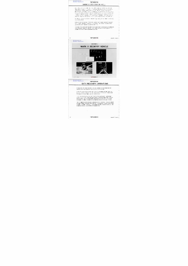
M A R K 8 R E E N T R Y V E H IC L E
Wnen the take-ups in the RV are filled, the next in-line RV is enabled and the full RV is ejected from the
optimized pitched down SV at a 3 ft/second rate. The spin-up to 10 radians per second is accomplished via
hot gas generator to stabilize the RV during the retro rocket motor burn. The retro rocket provides a
1623 pound thrust to slow the RV for reentry. The despin system then slows the spin rate to 1.4 radians per
second, which provides the needed stability during the coast period and still permits the aerodynamic torques
to align the RV angle-of-attack with the flight path early in the reentry period. The drogue parachute is de-
ployed upon closure of an acceleration switch at approximately 60,000 ft altitude. The drogue parachute is
released and main parachute deployed upon closure of a barometric pressure switch at about 50,000 feet.
At 15,000 feet, the rate of descent is from 1200 to 1650 feet per minute, which is suitable for aerial recovery
by USAF JC130 aircraft.
Each RV has a base diameter of 57-1/2 inches and is 85 inches from the heatshield nose to the retro motor
nozzle. Maximum total weight of the RV and film is 1695 pounds. This consists of 956 pounds of RV and
equipment, 239 pounds for film take-ups, and 500 pounds of film.
The heatshield when removed shows the gold tape covered canister which is part of a passive on-orbit thermal
control system which, together with electrical heaters, maintains the desired canister temperature. The
propulsion truss assembly and SV attachment fittings are shown.0
36 O P S E C R E T /H
IF003W/2-093942-77
NRO APPROVED FORRELEASE 17 September 2011
8/4/2019 Project HEXAGON Overview
http://slidepdf.com/reader/full/project-hexagon-overview 37/125
TOP SECRET/HIF003W/2-093942-77 37
MIN SEC
IPIN-UP 0-02
2ETROGRADE 2:05
3PIN-DOWN 2:40
4RUSS SEPARATION 2:45
5TMOSPHERIC ENTRY 2:55
6ROGUE &MAIN CHUTE DEPLOYMENT 9:37
7EAT SHIELD SEPARATION 9:59
8ERIAL RECOVERY 27.55
SPIN-UP EVEN T R V W I TH O U T H E A T S H I EL D
R E C O V E R Y S E Q U E N C E
T O P SECRET/H
M A R K 8 R E E N T R Y V E H IC L E
T O P S E C R E T /H
NRO APPROVED FORRELEASE 17 September 2011
8/4/2019 Project HEXAGON Overview
http://slidepdf.com/reader/full/project-hexagon-overview 38/125
T-1
D A T A R E C O V E R Y O P E R A T IO N S
The target cone is 10 feet in diameter and 15 feet high. It contains the nylon load lines which are
engaged by hooks on the retrieval line loops deployed by the retrieval aircraft.
The minimum dispersal impact area applies to all normal film load with the maximum dispersal area
applicable to a maximum unbalanced film load. In an emergency, recoveries may be required outside
this designated area toward Midway Island or the California Coast.
If aerial retrieval is not accomplished, water recovery becomes a backup phase. When sea water
contacts a sensor, a relay closes the film canister vent valve and transfers vehicle power to the water
recovery beacon. A salt water corrosion plug will sink the recovery capsule in 48 to 60 hours after
water impact. This allows a reasonable time for location and pickup by Air Force and Navy forces.
If the RV significantly overshoots the specified impact point, it will be destroyed. This is accomplished
by ejecting the heatshield and deploying the drogue chute if aero drag has not produced 0.003 g by a given
time after RV separation. This results in the RV burning up when the atmosphere is encountered. This
provision has not been utilized on the HEXAGON program to date.
38 O P S E C R E T /H
IF003W/2-093942-77
0
NRO APPROVED FORRELEASE 17 September 2011

8/4/2019 Project HEXAGON Overview
http://slidepdf.com/reader/full/project-hexagon-overview 39/125
DISPERSAL IMPACT AREA
M A R K 8 R E C O V E R YCAPSULE
79I N I M U M 1 6 X 1 5 0 N M
M A X I M U M 3 2 X 3 0 0 N M
BIF003VV/2-093942-77
1 5 ° N
TOP SECR ET/H
1 6 0 ° W5 0 ° W
L O N G I T U D E
1 7 0 ° W
3 9
TOP SECRE T/H
D A T A R E C O V E R Y O P E R A T IO N S
T O P S E C R E T /HNRO APPROVED FORRELEASE 17 September 2011

8/4/2019 Project HEXAGON Overview
http://slidepdf.com/reader/full/project-hexagon-overview 40/125
M A R K 8 EQ U IP M E N TiThe film is shown passing through the RV. Transfer of film to this RV consists of transferring take-up
power, wrapping film on this take-up, cutting and sealing the film path on the exit side, followed by cuttingand sealing the inlet film path on the forward RV.
The RV base ablative cover consists of panels of ultra low density material. The base panel structures are
of fiberglass honeycomb sandwich construction. A laminate of graphite blankets over glass fiber blankets
covers the main parachute compartment. The circuit interrupter switch and wire bundles are mechanically
separated near the ablative surface by a guillotine prior to physical separation of the RV from the SV.
The bottom view shows the film on take-up A and B. The take-up drive motor and control electronics are
contained mainly within the take-up hub. The canister is shown removed for access to the take-up and the RV
equipment. This access greatly enhances film tracking alignments and testing during SV factory testing.
The RV assembly shows the structural frames within the RV which provide mechanical support for the take-up
assembly and RV equipment. Of the encapsulated volume inside the RV, 18 ft 3 is for the take-up assembly
and 13 ft3
is used by the RV equipment. The film stack diameter can be up to 35 inches. RV power distribu-
tion and event sequence control is provided by relays. Time delay relays are used to control sequence timing.
Instrumentation is provided for monitoring the deorbit-reentry events and temperature. This data is proc-
essed through the PCM commutator to the tracking and telemetry transmitter.
40 O P S E C R E T /H
17003W/2-093942-77
NRO APPROVED FORRELEASE 17 September 2011

8/4/2019 Project HEXAGON Overview
http://slidepdf.com/reader/full/project-hexagon-overview 41/125
ACCESS DOORF I L M PA TH O U TL E T
TOP SECRET/HIF003W/2-093942-77
F IL M O N R V T A K E U P S
I N L E T
A R T I C U L A T O RS U P P O R T
I I .--SB A
SPOOL-AR OTATION S P O O L - BR OTATION
O U T L E T
F I LM C H U T E
A R T I C U L A T O R
C U T T E R / S E A L E RA S S E M B L Y
_LA_
F I LM T H R O U G H R V
PROPULSION TRUSSS P I N - O F F C O N N E C T O R
CIRCUITI N T E R R U P T E R
S W I T C H
VH F A N T E N N A
P A R A C H U T ESOFT COVER
DROGUEMORTAR COVER
RV ASSEMBLY
ACCESS DOORF I L M PA TH I NL E T
RV BASE ABLATIVE COVER
TOP SECRET/H
M A R K 8 R V E QU IP M E N T
T O P S E C R E T /H
NRO APPROVED FORRELEASE 17 September 2011

8/4/2019 Project HEXAGON Overview
http://slidepdf.com/reader/full/project-hexagon-overview 42/125
S E A R C H C A P A B I L IT Y
T O P S E C R E T /H 431F003W/2-093942-77
T O P S E C R E T /HNRO APPROVED FORRELEASE 17 September 2011

8/4/2019 Project HEXAGON Overview
http://slidepdf.com/reader/full/project-hexagon-overview 43/125
S E A R C H /S U R V E IL LA N C E O P E R A T IO N S211 1 1 1 1
Scanning is accomplished by continuous rotation of the optical bars at a rate to produce a nominal
three percent frame-to-frame overlap allowance at nadir. The minimum scan sector is 30 degrees,
the maximum 120 degrees. To achieve stereoscopic coverage the port camera (camera-A) looks
forward 10 degrees and the starboard camera (camera-B) looks aft 10 degrees. At 88 nm altitude the
interval of the forward to the aft frame is 31 nm. Since camera-B lags camera-A with respect to
ground cover at nadir, the shutter of camera-B is inhibited for the first three frames and camera-A
for the last three frames of each operation. Either camera can be operated separately in a mono mode.
The ground format varies with altitude, scan sector, and scan center. With the optical bars counter-
rotating the ground formats for the two camera are not the same. The area of coverage per mission
also varies with the average scan sector of acquisitions. At ±45 degrees average scan with the maxi-
mum supply of 1414 black and white film. gross stereo coverage of 20 million square nautical miles
(M sq. nm) can be achieved at an average acquisition altitude of 88 nm with the current film transport
system. At an average scan of ±30 degrees, this coverage would be reduced to 16 M sq. nm.
44 O P S E C R E T /H
IF003W/2-093942-77
NRO APPROVED FORRELEASE 17 September 2011

8/4/2019 Project HEXAGON Overview
http://slidepdf.com/reader/full/project-hexagon-overview 44/125
2 P A N C A M E R A S
T O P S E C R E T / Hr m w w -
S E A R C H /S U R V E IL L A N C E O P E R A T IO N S
AFT /F R A M E
LINE OF FLIGHT
BIF003W/2-093945-77
/***-O B J E C T I V E S
CONTINUOUS SEARCH
PAYLOAD DATAS T E R E O P A N O R A M I C C A M E R A
60-INCH FOCAL LENGTH246,000 FT - 6 .6 INCH UTB F ILM
FORMAT - VARIABLEC OV E RA GE - 20 M S Q NM / M I SS I ON S T E RE O
- R ESO LU T IO N - 2 . 1 TO 7 . 5 FEET G R D( N A D I R T O 60 D E G R E E S )
F O U R R E C O V E R Y V E H I C L E SFOR PANORAMIC CAMERAS
O R B I T A L D A T AINCLINATION - 96 .4 DEGREES SUN- SYNCHRONOUS
AVERAGE PERIGEE - 88 NMA V E RA GE A POGE E - 155 NMMISSION L IFE - UP TO 180 DAYS
'5T O P S E C R E T /H
NRO APPROVED FORRELEASE 17 September 2011

8/4/2019 Project HEXAGON Overview
http://slidepdf.com/reader/full/project-hexagon-overview 45/125
NRO APPROVED FORRELEASE 17 September 2011

8/4/2019 Project HEXAGON Overview
http://slidepdf.com/reader/full/project-hexagon-overview 46/125
T O P S E C R E T / HNRO APPROVED FORRELEASE 17 September 2011

8/4/2019 Project HEXAGON Overview
http://slidepdf.com/reader/full/project-hexagon-overview 47/125
T H E C A P IT O L
Conditions for this photograph are: Mission 1212-3, op 723, frame 002 forward, 002 aft, -24° scan,
15 October 1976, stereo, 20X magnification of the Capital, Washington, D. C.
The ability of the HEXAGON camera to photograph targets in stereo greatly increase its capability as
an intelligence gathering tool. All subjects reveal more information in three dimensions because they
assume all the spatial dimension we are used to seeing. This allows determination of structure
height, seeing the real shape of unusual objects and separation of items from confusing background.
The item at (A) is the press box for the last presidential inauguration. It was still under construction.
The relief of the trees at (B) shows how cover for troops and vehicles can be interpreted and targets
located.
During the time between exposures, vehicles (C) moved to new locations. The scale of the photograph
and time interval are known so their speed can be calculated.
Stereo imagery generally increases the information content of a target area and provides for a more
complete and accurate intelligence reporting.
T O P S E C R E T / H8 BIF003W/2-093942-77
NRO APPROVED FORRELEASE 17 September 2011

8/4/2019 Project HEXAGON Overview
http://slidepdf.com/reader/full/project-hexagon-overview 48/125
NRO APPROVED FORRELEASE 17 September 2011

8/4/2019 Project HEXAGON Overview
http://slidepdf.com/reader/full/project-hexagon-overview 49/125
NRO APPROVED FORRELEASE 17 September 2011

8/4/2019 Project HEXAGON Overview
http://slidepdf.com/reader/full/project-hexagon-overview 50/125
TOP SECRET/H
PAN ORA M IC SYSTEM FLEXIB IL ITYr-1
F R A M E S
110 NM CAPABILITY
S C A N S E C T O R S
30, 60, 90, 120
D E G R E E S A T F U L LS C A N
CENTER OF SCAN
0, *15, ±30, ±45D E G R E E S
L
J
CONTIGUOUS AREAACQUISIT IONS
BIF003W/2-093942-77 TOP SECR ET/H
T O P S E C R E T /H
NRO APPROVED FORRELEASE 17 September 2011

8/4/2019 Project HEXAGON Overview
http://slidepdf.com/reader/full/project-hexagon-overview 51/125
5°SCAN AN GLE MARKS
C O N T IG U O U S W ID E A R E A C O V E R A G E
r START OF FRAMEiS T A R T O F O P E R A T I O N
d r — C A M E R A I D E N T I F I C A T IO N ( "A " O N L Y )
F I L M T R A V E LDIRECT ION
31.4" = 30° SCAN (MIN)
FRAME 1 FORMAT
VANDENBERG AFB IMAGE
2.5"
IRAME 2 FORMAT
1 3
6 .6"
AP P RO X I M A T E L Y P ARAL L E L T O •S V G R O U N D T R A C K
•• •• •• •• F IL M S E G M E N T ••• ( F U L L S C A L E ) • TIMING DOTS
E V E R Y 2 M I L L I-S E C O N D S
S V T IM E W O R D( O N C E P E R F R A M E )
TOP SECRET/Llik BIF003W/2-093942-77
NRO APPROVED FORRELEASE 17 September 2011

8/4/2019 Project HEXAGON Overview
http://slidepdf.com/reader/full/project-hexagon-overview 52/125
T O P S E C R E T / H
M ID E A ST C O V E R A G E
NRO APPROVED FORRELEASE 17 September 2011

8/4/2019 Project HEXAGON Overview
http://slidepdf.com/reader/full/project-hexagon-overview 53/125
A typical area search acquisition by HEXAGON is the coverage of the Eastern
Mediterranean. This is a single two-minute stereo operation. At 90 nm altitude
and a cross track scan of ±45 degrees, the primary areas of interest in Western
Syria, Lebanon, Israel, Western Jordan, part of the Sinai Peninsula, and part of
Cyprus are acquired as a contiguous area. At ±60 degrees scan, the additional
width permits a greater tolerance in the longitudinal position of the flight path in
addition to a wider area searched. In an extreme crisis, through the control of
the orbit, a daily report of the acquisition of these areas is achievable.
54 T O P S E C R E T /H BIF003W/2-093942-77

8/4/2019 Project HEXAGON Overview
http://slidepdf.com/reader/full/project-hexagon-overview 54/125
T O P S E C R E T /H
B R O A D A R E A A C Q U IS IT IO NNRO APPROVED FOR
RELEASE 17 September 2011

8/4/2019 Project HEXAGON Overview
http://slidepdf.com/reader/full/project-hexagon-overview 55/125
amisswatigsaazirmsterfaxasonsa.
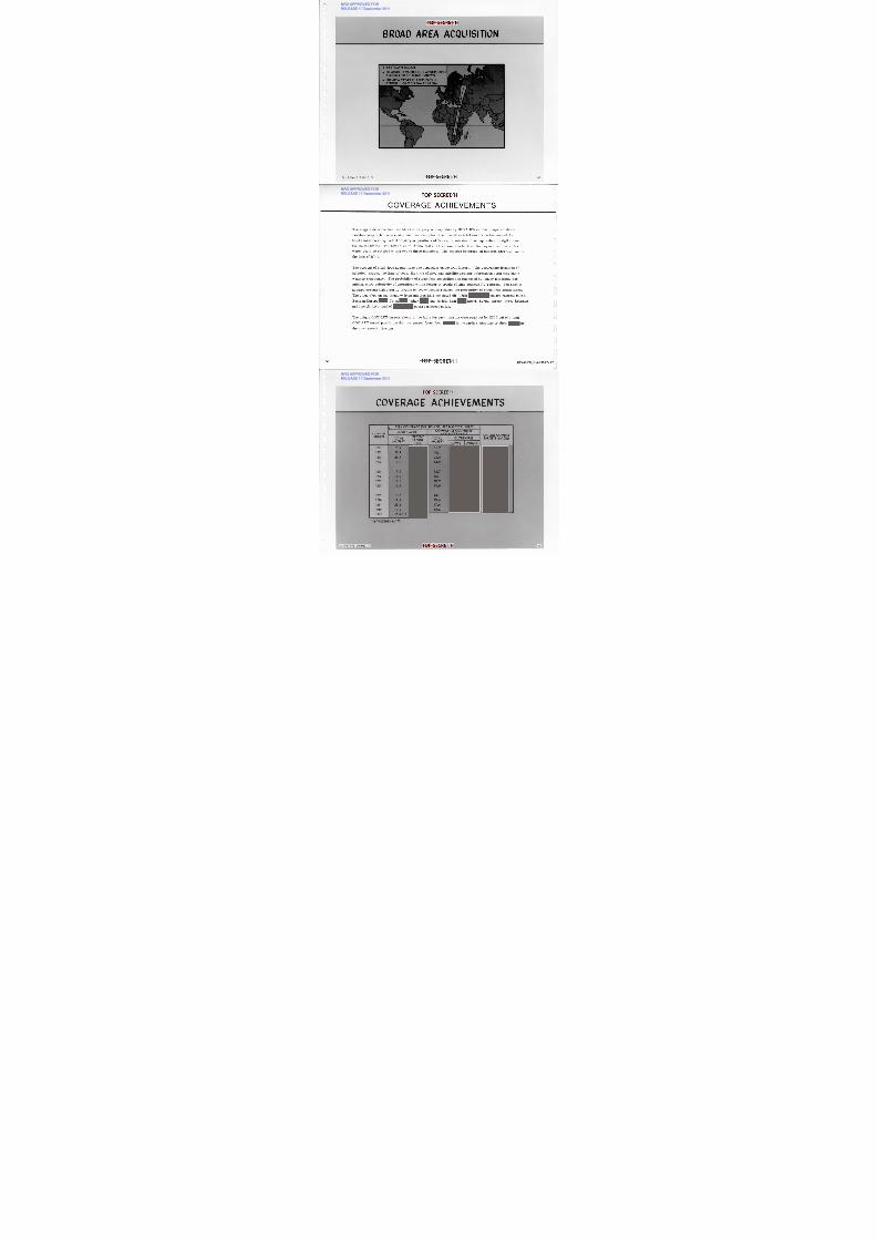
The HEXAGON system can provide broad area acquisition with a contiguous area
acquisition of considerable magnitude along the line of flight using any of the se-
lectable scan sector and scan center combinations. The maximum 120 degree swath
width is illustrated for a 20 minute contiguous operation acquiring a 4800 nm long
area, 32 2 nm wide, extending from Western Russia, through the Eastern Mediterranean,
down into Southern Africa. The total area approximates 1.54 M sq nm with an average
altitude of 88 nm.
56 T O P S E C R E T /H BIF003W/2-093942-77
U
-1 2
T O P SECREVH
NRO APPROVED FORRELEASE 17 September 2011

8/4/2019 Project HEXAGON Overview
http://slidepdf.com/reader/full/project-hexagon-overview 56/125
T O P S E C R E T /HIF003W/2-093942-77
BROA D A REA A CQU ISIT ION
± 60° SCAN SECTOR
20 MINUTE CONTIGUOUS ACQUISITIONALONG LINE OF FLIGHT SHOWN
THE AREA COVER ON THIS PASS ISAPPROX 1.54 M SQ NM AT 88 NM
57
NRO APPROVED FORRELEASE 17 September 2011

8/4/2019 Project HEXAGON Overview
http://slidepdf.com/reader/full/project-hexagon-overview 57/125
NRO APPROVED FORRELEASE 17 September 2011

8/4/2019 Project HEXAGON Overview
http://slidepdf.com/reader/full/project-hexagon-overview 58/125
T O P S E C R E T /H
S E A R C H G L O B A L C O V E R A G E
NRO APPROVED FORRELEASE 17 September 2011

8/4/2019 Project HEXAGON Overview
http://slidepdf.com/reader/full/project-hexagon-overview 59/125
4 -4
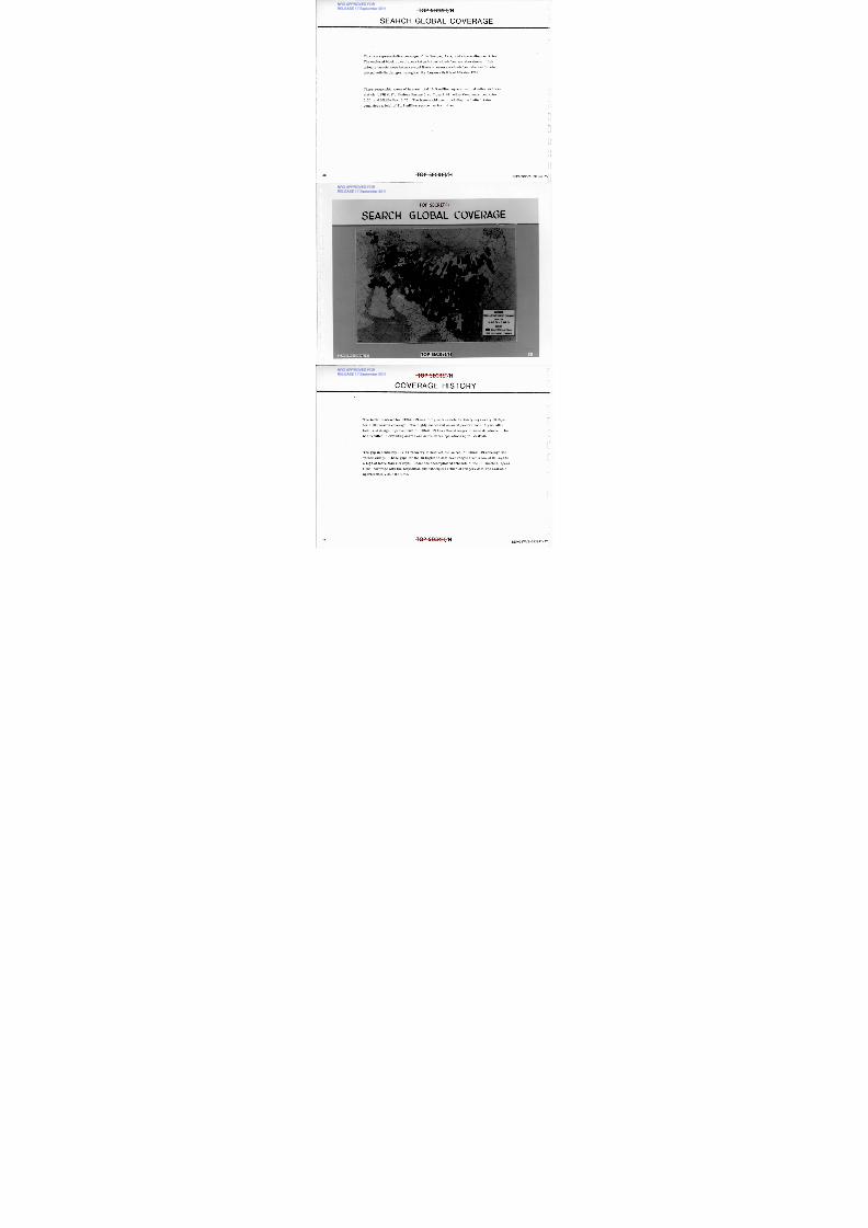
This is a representative coverage of the Europe, Asia, and surrounding countries.
The enclosed block or cell areas taken but not cloud-free are also shown. High
priority targets were taken several times to ensure a cloud-free take and to note
ground activity changes throughout the four-month life of Mission 1209.
These geographic areas of interest total 10.9 million square nautical miles and con-
sist of: USSR 6.87, Eastern Europe 0.4, China 2.82, other Communist countries
0.56, and Middle East 0.25. The free-world area, including the United States,
comprises a total of 41.3 million square nautical miles.
60 T O P S E C R E T /H BIF003W/2-093942-77
TOP SECRET/H
. H NRO APPROVED FORRELEASE 17 September 2011

8/4/2019 Project HEXAGON Overview
http://slidepdf.com/reader/full/project-hexagon-overview 60/125
S EA R C H G L O B A L C O V E R A G EI
E U R A S I A
C O M P O S I T E I N T E L L I G E N C E S U M M A R Y
M S N 1 2 0 9
30 OCT 74 - 7 MAR 75
LEGEND
N M C L E A R S T E R E O C O V E R A G E
C L E A R M O N O C O V E R A G E
4,
TOP SECRET/H 61
T O P S E C R E T /H
C O V E R A G E H IS T O R Yr-c
NRO APPROVED FORRELEASE 17 September 2011

8/4/2019 Project HEXAGON Overview
http://slidepdf.com/reader/full/project-hexagon-overview 61/125
The initial contract for HEXAGON was to fly each vehicle for thirty days every 60 days
for a 50% search coverage. The highly successful on-orbit performance, higher alti-
tude, and design improvements of HEXAGON has allowed longer mission durations. This
has resulted in extending search and surveillance operations up to 17 6 days.
The gap in continuity (RV #4 recovery to next vehicle launch) of HEXA GO N coverage has
varied widely. These gaps for the 13 flights to date have ranged from a low of 39 days to
a high of more than 200 days. Under the accomplished schedule of the 13 launches, opera-
tional coverage with the acquisition and subsequent return of imagery data was available
approximately half the time.
L
L
62 T O P S E C R E T /H BIF003W/2-093942-77
TO P S E CRE T/ H
NRO APPROVED FORRELEASE 17 September 2011

8/4/2019 Project HEXAGON Overview
http://slidepdf.com/reader/full/project-hexagon-overview 62/125
C O V E R A G E H I S T O R Y
LAUNCH MOON DAY1 2 0 1 or1202
G A P - D A Y S120320 420 5
8 11—k--;1I I39
1 2 0 8
1 481 2 0 7 1 2 0 6
62
1973
1 2 1 02 1 12 1 2
W 4,02
1 9 7 6
1 2 1 3 '
1 9 7 7
TO P S E CRE T/ HIF003W/2-093942-77
T O P S E C R E T /H
IN C R E A S IN G D U R A T IO N B E T W E E N R E C O V E R IE S
-0
NRO APPROVED FORRELEASE 17 September 2011

8/4/2019 Project HEXAGON Overview
http://slidepdf.com/reader/full/project-hexagon-overview 63/125
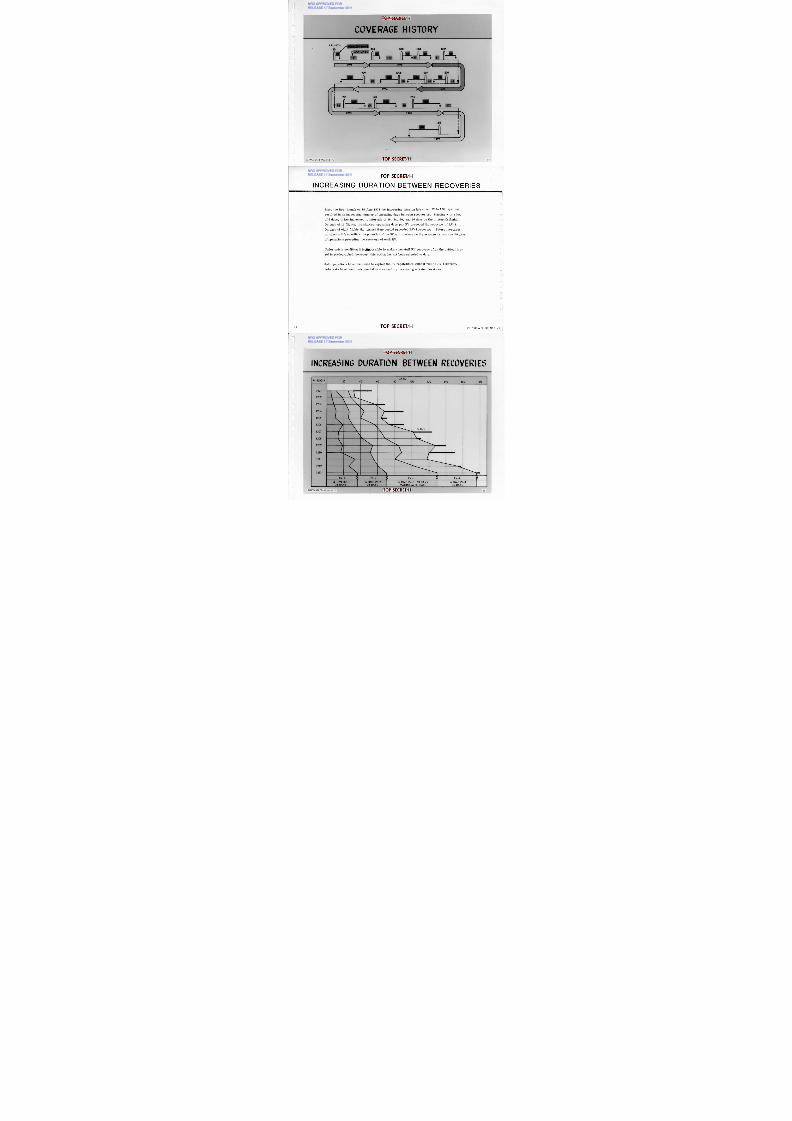
Since the first launch on 15 June 1971 the increasing mission life (from 32 to 176 days) hasresulted in an increasing number of operating days between recoveries. Starting with a low
of 5 days, it has increased to intervals of 36, 34, 60, and 46 days on the thirteenth flight.
On each of 11 flights, the shortest operating days per RV preceded the recovery of RV-1.
On each of eight flights the longest time period preceded RV-4 recovery. Future increases
in mission life to utilize the potential of the SV will produce on the average as many as 60 days
of operations preceding the recovery of each RV.
Under crisis condition it ispossible to make a non-full RV recovery after the critical tar-
get is photographed; however, this option has not been selected to date.
Solo operations have been used to exploit the SV capabilities without risk to RV recovery.
Solo tests have been instrumental in successfully increasing mission durations.
U
64 O P S E C R E T /H
IF003W/2-093942-77
TOP SECRET/H
NRO APPROVED FORRELEASE 17 September 2011

8/4/2019 Project HEXAGON Overview
http://slidepdf.com/reader/full/project-hexagon-overview 64/125
INCREASING DU RATION B ETW EEN RECOVERIES1 0 -
MISSIOND A Y S
2 00000 02 04 06 08 0
1 2 0 1
1 2 0 2
1 2 0 3
1 2 0 4
1 2 0 5
1 2 0 6
1 2 0 7
1 2 0 8
1 2 0 9
1 2 1 0
1 2 1 1
1 2 1 2
1 2 1 3
S O L O
lihkNaa
R V - 1RV-2 gV - 3vvV-4 3
A TIME RV-136 D A Y S
A TIME RV-234 DAYS
A TIME RV-30 DAYSM A XIM U M T O D A T E
A TIME RV-446 DAYS
BIF003W/2-093942-77 TOP SECRET/H
T O P S E C R E T / H
SO-255 COLOR FILM
NRO APPROVED FORRELEASE 17 September 2011

8/4/2019 Project HEXAGON Overview
http://slidepdf.com/reader/full/project-hexagon-overview 65/125
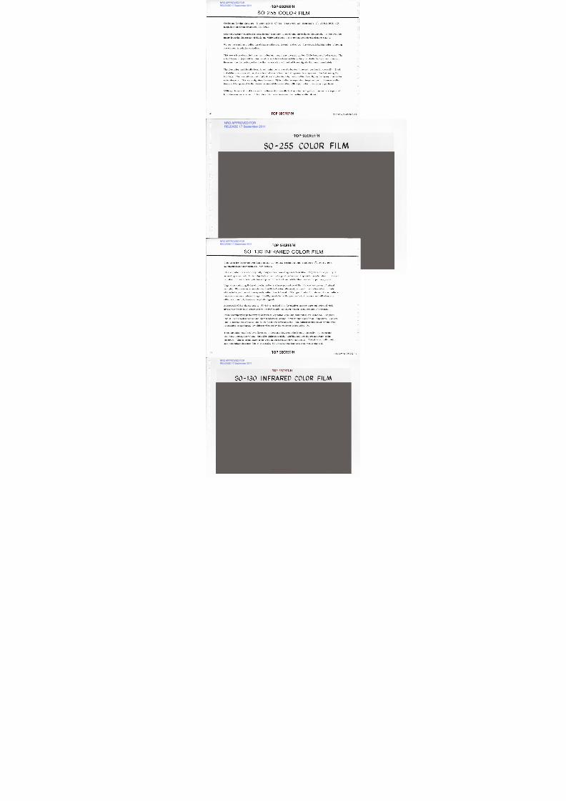
Conditions for this photo are: Mission 1208-4, OP 733, Frame 006, Aft, Scan Angle -2°, 15 July 1974, 40X
magnification of San Francisco, California.
Color photography contributes an additional dimension to search and surveillance photography. It removes the
image from the abstraction of black-and-white and places it in a context we understand more readily.
We see the world as a collection of shapes with size, texture, and color. A photograph lacking color is lacking
one element in relation to reality.
This scene is photographed in natural color and many items are readily identifiable because of color cues. The
school buses at (A) could be interpreted as such in black-and-white by their proximity to the school complex.
However, the distinctive yellow hue that we associate with school buses signals their use immediately.
The blue color traditionally found in swimming pools is easily located in several residential areas (B). Black
and white coverage would require a detailed search because their geometric shapes would be lost among the
buildings. The competition pool at (C) shows varying depth by the transition from lighter to darker blue as the
water deepens. This same signature is seen at (D) indicating an expensive, in-ground pool. Numerous other
items will be apparent to the viewer because of its association with object color in everyday experience.
Military, industrial, and transportation items also have distinctive color coding signatures and are separated
from the enormous amount of photo detail in the same manner as the items cited above.
T O P S E C R E T / H6 BIF003W/2-093942-77
NRO APPROVED FORRELEASE 17 September 2011

8/4/2019 Project HEXAGON Overview
http://slidepdf.com/reader/full/project-hexagon-overview 66/125
T O P S E C R E T /H
S O -1 30 IN F R A R E D C O L O R F IL M
NRO APPROVED FORRELEASE 17 September 2011

8/4/2019 Project HEXAGON Overview
http://slidepdf.com/reader/full/project-hexagon-overview 67/125
Conditions for this photo are: Mission 1213-3, OP 713, Frame 006, aft, scan angle 0°, Oct 14, 1976,
5X magnification near Santa Fe, New Mexico.
Infrared color films were originally designed as a camouflage detection film. They have the capability of
separating man-made, hidden objects from natural vegetation because of special characteristics of infrared
radiation. Resolution is quite low compared to the black-and-white films used as the primary payload.
Vegetation containing living chlorophyl reflects a large percentage of the infra-red component of natural
sunlight. Plants under stress (having insufficient water, diseased, etc.) will have a breakdown in their
chlorophyl structure and consequently reflect less infrared. This type of color film shows infrared reflec-
tance as a magenta colored image. Healthy vegetation will appear as bright magenta and will change ineither color or brightness as the plants degrade.
As a result of this characteristic, SO-130 is an ideal film for monitoring crop vigor and potential yield
giving very basic intelligence data on the food supply and import/export requirements of a country.
In the accompanying photo varying degrees of vegetation vigor and distribution are indicated. The plant-
ings at (A) are well advanced and show local irregularities in water supply and/or soil capability. Pasture
land is seen as healthy at (B) and fallow fields are obvious at (C). The natural ground cover for the area
is indicated as arid area, low chlorophyl cover by the response indicated by (D).
There are also notable color differences in the ponds that cross the format diagonally. As suspended
sediments increase in volume, the color shifts toward the light blue and into the green portion of the
spectrum. This is an indicator of the erosion and retention of valuable soils. Though marginally useful
as a comouflage detection film at this scale, SO-130 is outstanding as a crop monitoring tool.
T O P S E C R E T /H8 BIF003W/2-093942-77
NRO APPROVED FORRELEASE 17 September 2011

8/4/2019 Project HEXAGON Overview
http://slidepdf.com/reader/full/project-hexagon-overview 68/125
T O P S E C R E T /H
F IL M T Y P E S F LO W NISZENUNIIMOF
NRO APPROVED FORRELEASE 17 September 2011

8/4/2019 Project HEXAGON Overview
http://slidepdf.com/reader/full/project-hexagon-overview 69/125
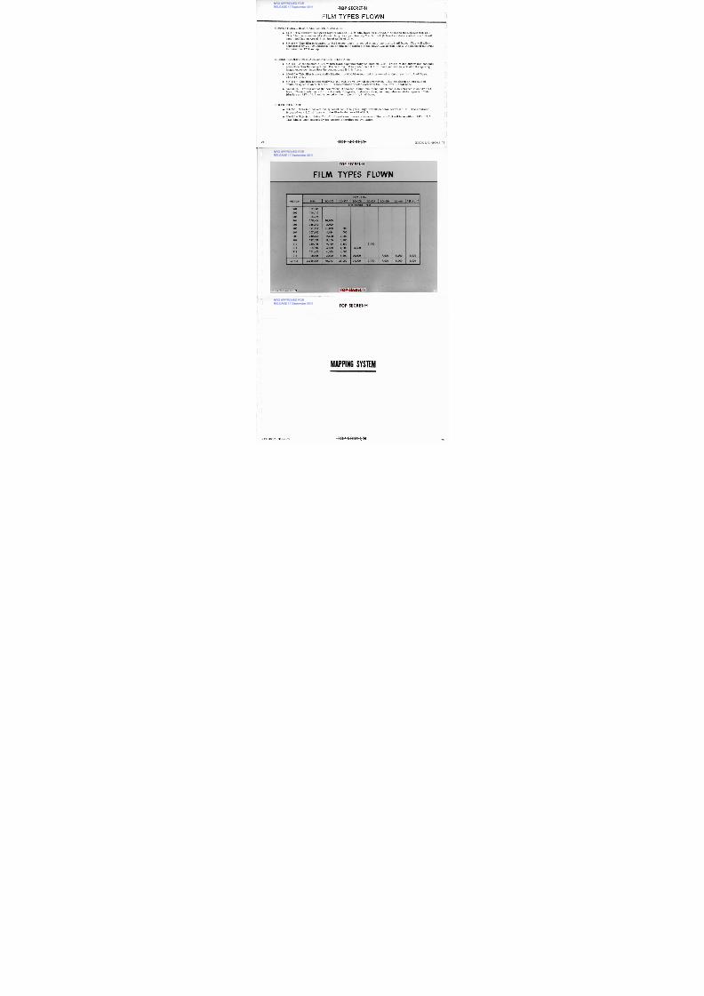
CONVENTIONAL BLACK AND WHITE FILMS ARE:
1414 — The standard fine grain high resolution B & W film flown on HEXAGON Missions through Mission 1213.
This film has an extended red sensitivity, is approximately 2 mils thick (0.5 mil emulsion coated on a 1.5 mil
base), and has an Aerial Film Speed (AFS) of 15.0.
SO-208 — This film is identical to 1414 except that it is coated on an ultra-thin 1.2 mil base. This will allowapproximately 20,000 additional feet of film to be utilized in the HEXAG ON system and is the standard material
for missions 1214 and up.
HIGHER RESOLUTION BLACK AND WHITE FILMS ARE:
SO-124 — A panchromatic B & W film flown experimentally on Mission 1210. This film has higher low-contrastresolution than the conventional B & W films. It is coated on a 1.5 mil base and has an AFS of 6.0 requiring
longer exposure times than the conventional B & W films.
SO-460 — This film is essentially identical to SO-124 except that it is coated on the ultra-thin 1.2 mil base.
The AFS is 6.0.
SO-464 — This film is essentially SO-460 with the yellow AH dye removed. This results in an increase ofemulsion speed to an A FS of 10.0. This emulsion is also coated on the ultra-thin 1.2 mil base.
Aerial 15 — This is one of the new "Mono Dispersed Cubic" emulsions sometimes also referred to as "J" coat-ings. These emulsions exhibit extremely fine grain, high resolution, and very slow emulsion speeds. Thisfilm has an AFS of 6.6 and is coated on the ultra-thin 1.2 mil base.
COLOR FILMS ARE:
SO-255 — This is a conventionally sensitized, fine grain, high-definition color reversal film. The emulsion
is coated on a 1.5 mil base with the film having an AFS of 9.5.
SO-130 — This is a "False Color" infrared sensitive color reversal film on a 1.5 mil base with an AFS of 7.5.This film is used extensively for economic intelligence evaluation.
E l
T O P S E C R E T /H0 BIF003W/2-093942-77
TO P S E CRE T/ H
NRO APPROVED FORRELEASE 17 September 2011

8/4/2019 Project HEXAGON Overview
http://slidepdf.com/reader/full/project-hexagon-overview 70/125
F IL M T Y P E S F L O W N
F IL M T Y P E S
MISSION A E R I A L 1 54 1 4SO-255 I S O - 1 3 0 I S O - 2 0 8 I S O - 1 2 4 I S O - 4 6 0 I S O - 4 6 4Fi lm Footage - Feet
1 2 0 1
1 2 0 2
1 2 0 3
1 7 2 , 6 4 0
1 5 6 , 1 1 5
1 8 5 , 3 2 5
1 2 0 4 208,454 10,0001 2 0 5 216,010 2,000
1 2 0 6 1 9 1 , 0 1 7 21,000 5 0 0
1 2 0 7 207,832 4,984 5 0 0
1 2 0 8 210,069 2,588 3,000
1 2 0 9 217,338 8,150 3,400
1 2 1 0 210,156 9,150 3,150 3,750
1 2 1 1 1 5 3 , 9 4 2 4,500 4,500 4,500
1 2 1 2 231,450 4,500_ 4,500
1 2 1 3 1 9 8 , 5 3 6 3,500 5,500 20,000 7,000 8,000 2,000
T O T A L S 2,558,884 70,372 25,050 24,500 3,750 7,000 8,000 2,000
BIF003W 2-093942-77 71O P S E C R E T /H i
T O P S E C R E T /H
NRO APPROVED FORRELEASE 17 September 2011

8/4/2019 Project HEXAGON Overview
http://slidepdf.com/reader/full/project-hexagon-overview 71/125
M A P P I N G S Y S T E M
T O P S E C R E T /H1F003W/2-093942-77 73
T O P S E C R E T /H
M A P P IN G C A M E R A O P E R A T IO N
NRO APPROVED FOR
RELEASE 17 September 2011

8/4/2019 Project HEXAGON Overview
http://slidepdf.com/reader/full/project-hexagon-overview 72/125
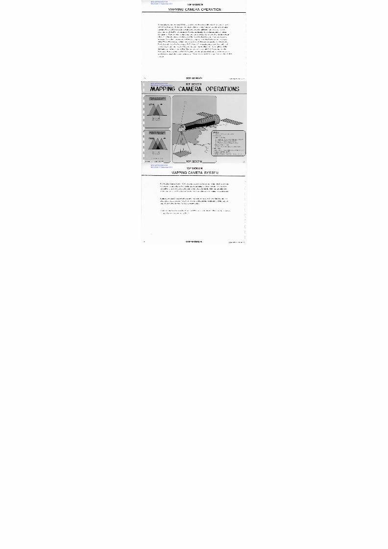
The mapping camera system (MCS) is utilized to provide cartographic control for compilation of
1:50, 000 scale maps. Photogrametric data is achieved by simultaneously acquiring overlapping
terrain and star field photographs through three precisely calibrated lens systems. Control
points are established by measurements of prominent imagery on overlapping pairs of terrain
photography. Measurements of star image locations on stellar frames provide an accurate orien-
tation of the terrain camera axis in space at the time of each photograph. Stereo photography,
necessary for vertical measurements of terrain imagery, is acquired in two stereo modes pro-
viding 70% or 55% overlap. A third mode is used to provide mono photography with 10% overlap.
The high resolution and wide coverage (70 X 140 nm) of the terrain camera provide a useful tool
in searching for primary targets of interest and earth survey objectives. On completion of the
MCS mission, the terrain and stellar films are returned in a single Mark V recovery vehicle.
The doppler beacon system and NAVPAC system provides ephemeral information which accurately
establishes camera/vehicle position in space. These data are needed to support mensuration of MCS
imagery.
74
O P S E C R E T /H
IF003W/2-093942-7
T O P S E C R E T /H
M A P P IN G C A M E R A O P E R A T IO N SNRO APPROVED FOR
RELEASE 17 September 2011

8/4/2019 Project HEXAGON Overview
http://slidepdf.com/reader/full/project-hexagon-overview 73/125
T E RRA I N M A P P I NG C A M E RAB I LA P P H O T O G R A P H Y
5 5 % O V E RLA P
1 0 B T E C T I V E S
M A P P I NG A ND G E O D E T I C S URV E Y
P A Y LO A D D A T A
M A P P I NG C A M E RA
3,300 FEET - 9 .5 INCH EK 3414 F ILM (TERR AIN)
2,000 FEET - 70 MM FILM (STELLAR)F O R M A T - 1 34 X 6 7 N M A T 8 8 N MC O V E R A G E - 5 .4 M S Q N M / M I S S IO N
ONE RECOVERY VEHICLE
FOR TERRAIN AND STELLAR CAMERA FILMS
O R B I T A L D A T A
IN C L IN AT IO N - 9 6 . 4 D EG R EES SU N - SYN C H R O N O U SAVERAGE PER IGEE - 88 NMA V E RA G E A P O G E E - 1 55 NMMAP P IN G M ISS IO N D U R AT IO N - U P T O 120 D AYS
75
70% OVERLAP
AT 88 N M . AL T IT U D E
BIF003W/2-093942-77 T O P S E C R E T /H
T E RRA I N M A P P I NG C A M E RA
TRILAP PHOTOGRAPHY
T O P S E C R E T /H
M A P P IN G C A M E R A SY S T EM
NRO APPROVED FOR
RELEASE 17 September 2011

8/4/2019 Project HEXAGON Overview
http://slidepdf.com/reader/full/project-hexagon-overview 74/125
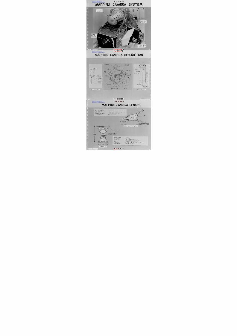
The Mapping Camera System (MCS) structure supports and positions the individual subsystems
with respect to each other and within the space constraints of the SV shroud. The loads are
transmitted to six structural attach points on the vehicle bulkhead. Pitch and yaw alignment
of the structure to the SV attitude reference module is achieved by shimming the attach points.
Temperature control is achieved by passive means (paint, tape, multilayer blankets and thin
metal sheets, i. e. , cocoons) for all but the precise temperature requirements of the lens sys-
tem, which employs heaters for their accurate control.
Electrical interfaces between the SV and the MCS are at the bulkhead. All command, telemetry,
timing and power are provided by the SV.
T O P S E C R E T /H6 BIF003W/2-093942-77
TOP S E C R E T / H
M A P P IN G C A M E R A S Y S TE MNRO APPROVED FOR
RELEASE 17 September 2011

8/4/2019 Project HEXAGON Overview
http://slidepdf.com/reader/full/project-hexagon-overview 75/125
T O P S E C R E T /H
8
R E C O V E R YV E H I CLE
M U LT I LA Y E RB L A N K E T SI
w. I 1 1T E L L AR C A M E R AL IG H T B A F F L E
RTF00:3W 2-0 3 42-77 77
T O P S E C R E T /H
M APP IN G CAM ERA DESCRIPT IO N
NRO APPROVED FOR
RELEASE 17 September 2011

8/4/2019 Project HEXAGON Overview
http://slidepdf.com/reader/full/project-hexagon-overview 76/125
F R A M EA D V A N C E
2.76-IN
( 7 0MM)F I LM WI D T H
TITLE MARKS
- S T A R T O FO P E R A T I O N MA R K
4.33-IN.
(110 MM) DIAMETERM I N I M U M U S E F U LF O RM A T (RE F )
R E S E A U S E R I A L N O ,
O R I G I N O F R E S E A UR O W A N D C O L U M NNUMBERS (TYP)
10 M
10
DA TAB LO C K
10.75±
FRAMEL E N G T H T I T L E
4.330-IN
(110 MM)I MA G E
LE N G T H
STELLARSUPPLYASSEMBLY
STELLAR F ILMCHUTE
T E R R A I N S U P P L Y
ASSEMBLY
STELLARBAFFLE
STELLAR LENSES
M A R K V S A T E L L I T ER E C O V E R Y V E H I C L ET E L L A R A N D T E R R A I N
T A K E U P A S S E M B L Y
M A I NI N S T R U M E N TA S S E M B L Y
T E R R A I N L E N S
D I R E C T I O N
T H E R M A L S H U T T E R A S S E M B L Y
E L E C T R I C A L D I S T R I B U T I O NM A I N I N S T R U M E N T S Y S T E MN D P O W E RE L E C T R O N I C S A S S E M B L Y
PRESSURE M AKEUPFSYSTEM
-C o
- 9.44S-IN. FILM WIDTH (REF)
9.00IN.0 M M )
USEFULF O R M
O R MA T
FIDUCIALL O C A T I O N(4 PLACES)
T I TL E A RE A
o L2S TA RT O FO P E R A T I O N MA R K
TITLE MARKS
.y
D I R E C T I O N O F F L I G H TA N D F I L M A D V A N C E0
D A T A B L O C K L O C A T I O N( A P P LI E S T O F R A ME S H O W N )
RE S E A U S E RI A L NU M B E RS
O R I G I N O F R E S E A U R O WA N D C O L U M N N U M B E R S
S T E LL A R F O R M A TE R R A I N FO RMAT
78 O P S E C R E T /H
IF003W/2-093942-77
T O P S E C R E T /H
M APPING CAM ERA LENSES
NRO APPROVED FOR
RELEASE 17 September 2011

8/4/2019 Project HEXAGON Overview
http://slidepdf.com/reader/full/project-hexagon-overview 77/125
T O P SECRET/H1F003W/2-093942-, 79
L E N S F O C A L L EN G T HRELATIVE APERTURESEN SI T I V I T Y
B O RE S I G H T S TA B I L I TYF I E L D O F V I E W
1 0 . 0 I N C H E S1/2.06 th M A G N I T U D E ST A R S O R B R I G H T E R
2 A R C - S E C I N O P E R A T I O N1 6 B Y 2 5 DE G RE E S
STELLAR SHUTTER
SAFETY SHUTTER
I N H I B IT S E N S O R
E A RT H
S T E L L A R L E N S A N D B A F F L E
RE S E A U PL A T E
FILTER (WR ATTEN 2 1 )
ASP H ER IC SU R FACE
F O C A L L E N G T HREL. APERTURED I S T O R T I O N
STABILITYR E S O L U T I O NF I E LD O F V I E W
12.0 IN.1 /6 , 1 /14100 M I C R O N S M A X R A D I AL2 0 M IC R O N S M A X T A N G E N T I AL2 M I C R O N S I N O P E R A T I O N9 5 L /M M A W A R ( V E M O N 3 4 1 4 F I LM )38 BY 72 DEGREES
15.13-IN.
DIAM ETER
MAPPING
T O P S E C R E T /H
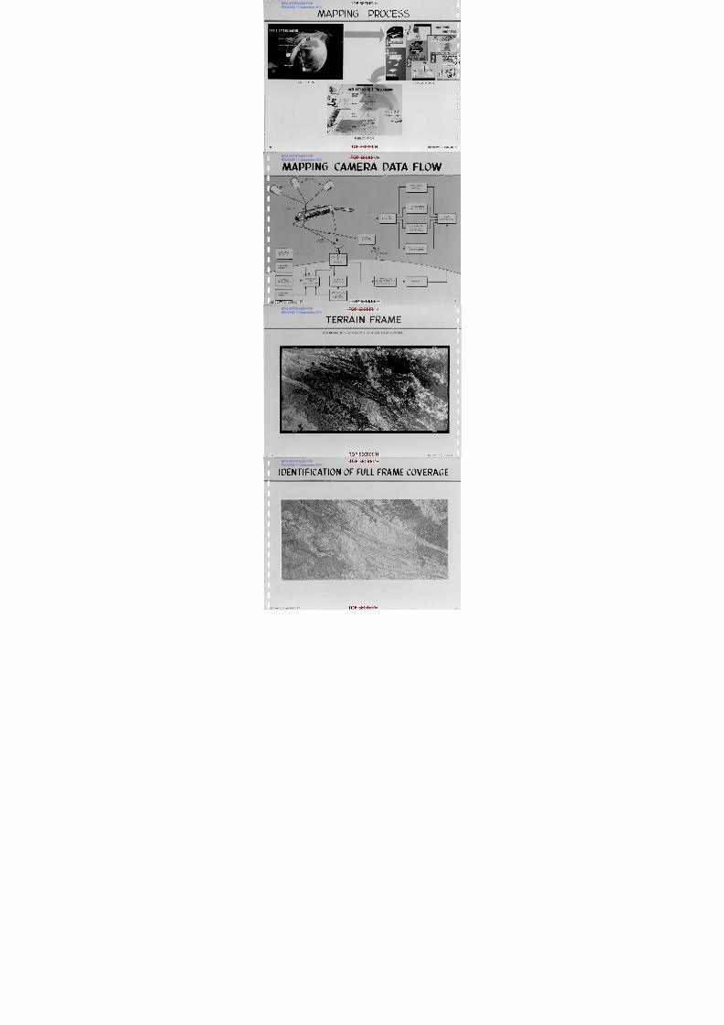
M A P P IN G P R O C ES S
NRO APPROVED FOR
RELEASE 17 September 2011

8/4/2019 Project HEXAGON Overview
http://slidepdf.com/reader/full/project-hexagon-overview 78/125
ACQUISITION
DATA EXTRIrly:
n
COLOR SEPARATION
DRAFTING
C O M P I L A T IO N O F M A P D A T A
EXPLOITATION
ESENTATION
•
C O MP U T I N G
I ?°11)
1,
S T E R E O P H O T O G R A P H I C P LO T T I N G
I
G R I D A N D
CONTROL
D A T A P R O C E S S I N GR O D U C T I O
RELIEF
M AP
DET AIL
N A M E S
PROCESS_
P O I N T MA R K I N G
lia- . • ---, ,
P O IN T ' M E A S UR IN G
O R B I T D E T E R M I N A T I O N
CELESTIAL MIS
SPACE MIMIC" AINUE ITATNII
COMA ORBIT
S T A T I O N
PUBLICATION
8 0
O P S E C R E T /H
IF003W/2-093942-77
N A V S A T S
T O P S E C R E T /H
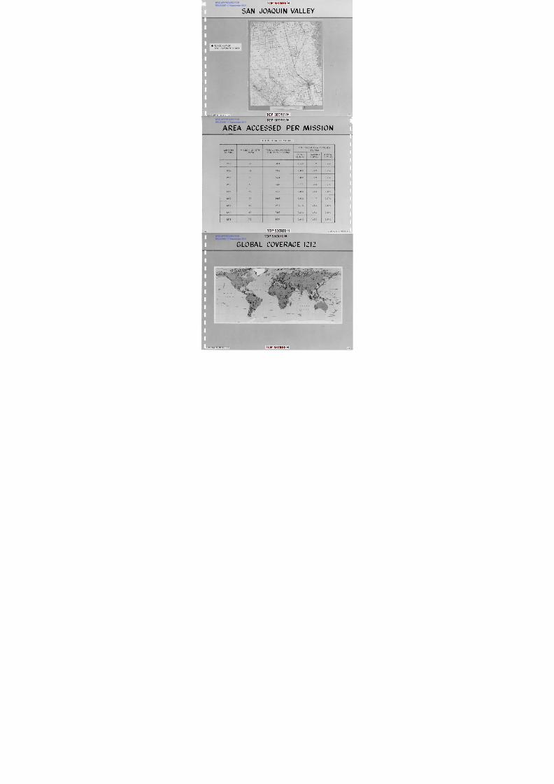
M A P P IN G C AM E R A D A T A FLO W
NRO APPROVED FOR
RELEASE 17 September 2011

8/4/2019 Project HEXAGON Overview
http://slidepdf.com/reader/full/project-hexagon-overview 79/125
-0-
C O N T R O L P O I N TM E N S U R A T I O N
T I M E W O R DR E A D O U T
O R I E N T A T I O ND E T E R M I N A T I O N
FILMR E C O V E R Y
M A PC O M P I L A T I O N
F IL M A N D L E N S
D I S T O R T I O NC O R R E C T I O N
PALLETD O W N L I N KO W N L I N K
DOPPLERB E A C O N
M A P A R E AP R IO R ITY
T R A N E T
A S G L S
STC-RTSEPHEMERIS
P R E D I C T I O N
C A M E R APARAMETERS
C O M M A N DL O A D
G E N E R A T I O N
T M D A T AA N A L Y S I S
N A V P A C A N DD O P P L E R B E A C O N
D A T A A N A L Y S I S
W E A T HE RP R E D I C T I O N
BIF003W/2-093942-77
O P E R A T I N GM O D E
S E L E CTION
T O P S E C R E T /H 8 1
N A V P A C
EPHEMERIS
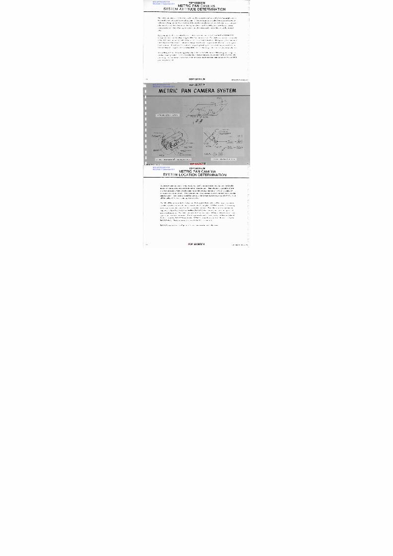
T O P S E C R E T /H
T E R R A IN FR A M E5 0 % R E D U C T I O N O F F U L L (9 x 1 8 IN C H ) T E R R A I N F R A M E
NRO APPROVED FOR
RELEASE 17 September 2011

8/4/2019 Project HEXAGON Overview
http://slidepdf.com/reader/full/project-hexagon-overview 80/125
8 2 O P S E C R E T /H
I F0 0 3W / 2 -0 9 39 42 - n -
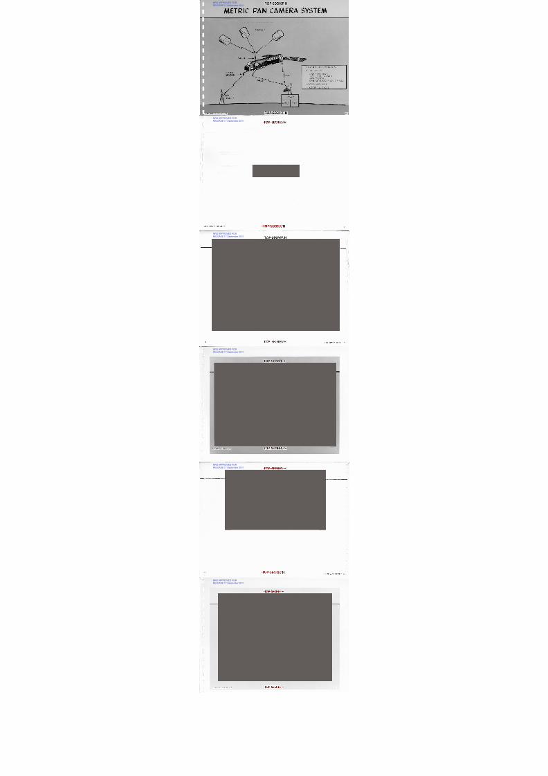
T O P S E C R E T /H
I D E N T I F IC A T I O N O F F U L L F R A M E C O V E R A G Eilliirmimmimmim ui
NRO APPROVED FOR
RELEASE 17 September 2011

8/4/2019 Project HEXAGON Overview
http://slidepdf.com/reader/full/project-hexagon-overview 81/125
T O P S E C R E T /H
O R IG IN AL DESIG N PHO TO
NRO APPROVED FOR
RELEASE 17 September 2011

8/4/2019 Project HEXAGON Overview
http://slidepdf.com/reader/full/project-hexagon-overview 82/125
6 W I LL IA M S A F B(20 X)
® EK 3 4 0 0 F I L M( M ISSION S 1205 - 1208 )
T O P S E C R E T /H4 BIF003W/2-093942-7V
T O P S E C R E T / H
P R O D U C T IMPROVEMENT
NRO APPROVED FOR
RELEASE 17 September 2011

8/4/2019 Project HEXAGON Overview
http://slidepdf.com/reader/full/project-hexagon-overview 83/125
• M I D L A N D T E X A SAI R TER MI N AL(20 X)
o E K 3 4 1 4 F IL M
( M IS S IO N S 1 2 0 9 A N D U P )
BIF003W/2-093942-77 8 5
TOP SECRET/H
STORAG E SITE4 1 1 1 1
41-IV
L'A".4);
▪•▪
NRO APPROVED FOR
RELEASE 17 September 2011

8/4/2019 Project HEXAGON Overview
http://slidepdf.com/reader/full/project-hexagon-overview 84/125
•
••• - -
wilOWISMISSs
•t""•• •
,••• • . ,•• - •4•1105`•••
II •
ticaPr •••
a m
••,L....
Jo
a
1 t o o j ' 1 1 .o o o •
' • • • • •• • • • • - •• ••I' ' ' . •I, 4 i y
•
177,PrPSn
., • ...no. • ••••0,1. . . "36,4 •••••••
.... ..„........Z•7:•7t-. 3...3
•:
'1 1 1 1 1 , o w . w o o e r t w r ,... .., .. or . 're" . . " . . ..•-nw--.4...-.- ..........
;
`. • *. sta45•1 11nrowsse,•••
I M
HWV
r w00
' ••••
0,‹lk•06.
0 0 % *40.-n •• 4.•4 1 1
•v.. '- -
i'?- It:mt o • i!• • • • - ••
I.,Lzoe79-7-ir":ifii:.1=Eikr37.,-TOP SECRET/HL=4--
• • • • .• • • • I/ /..71 P:qv -
n .14.,7• • • . . .
1"+V-* •• n • • • - ‘ 1 1 .
7 7 . •
wooPM%n
MSOe
I.O11
—ro••WO11
,•••W. •••T+iro,rslt
aso.%
n
't• .64.16.44-7.1:.!:::.t...
p r o 1 1 . 1
p r o P r %
t••
4
• • • •
1.•-I,
WI
UI
WsWS
PRI • ,
—•ot o•• •if •y• Tr -
DAVIS MONTHAN
AFB (40X)
MISSION 1211
EK 3414 FILM• • • • • • • • n ••
BIF003W/2-093942-77
II
NRO APPROVED FORRELEASE 17 September 2011

8/4/2019 Project HEXAGON Overview
http://slidepdf.com/reader/full/project-hexagon-overview 85/125
,
‘1 1,L
f
,ppno,B.1,44
'1
'mim .p
2
1,
1•
••-A
e1
:7.i:1cli
11
A,1
1
p
g
k
1
_13=
)1
1
i
EA ,uE
il
/=Am1k311
i
MICI""=N
Al *-.1—
?I
:n.21 I"11111•M
I
mA
11 1 1SJ!Allt=11g1 km1
o-1
!H:MzL1
,01I1
is
i1111111
.111 11=
I1m
Li1at'=-1
-m
t_•
1
14
:itoA 1111114401111iudwi•
20
1
1„iylun
Ho4061itoL\.„7
pran-
Ip
rara=41
t
1rsno
pm
-1_. a71
=ud.q1
.
.-1
0-1%i-„•Erogrmx11
0
10'ii
E0
1Q2
4•c
ln
,wr
vuo .iAf- _ .41-
raLgruE4ikPI
P-
-1111=gI!l1
-
-!1'
t746S
1
1
1
1121"I
MI
m
-74,1tn1
1C
41
ii;IILE'!""-
!•-
a1
v,gom
4o
mg
.'"P1M
"dptriInnowr5
1
m
t1;tr,
§Im
tai=111
141
I
1
fx
k-1
Ig=13
IV
' 1a1•om
m:i•+
•elow.
i
, -,,p
tccii!ortrxi,r:41t1:A
7-E f. 1
lie22
1
=
3
,
0
1
4
=
-f_r
1
IE
Tr;;N
0
Z1
1
1ra,1
k -tak
t2
.1Ir1
rfa
!
iA:VA
-
nm
aA1
74
1
1
g
11taA7-L-`
11
R
ro
sue
10M
IntArA.XI
!11
iir?-1I"
L1,2 2=
-
2%.4
:1 4
ngsn
.
0.
3nrm -i-N -I111114,1:.nB=6:!111111
1
glp
Vi"•11m .116
DF
f
L—
M
k
I
ccLUNRO APPROVED FORRELEASE 17 September 2011

8/4/2019 Project HEXAGON Overview
http://slidepdf.com/reader/full/project-hexagon-overview 86/125
•
.1.-.4 :ai1"1 -'r.; 4,1,Aroel:i,
4.L.=
c
L
4
1
=,1641 I ; .i'-
-4•
I
*4.
11e.--!69s
sff""--4t10t7r.3A
•V1." I''eI7•1111-e-"
P?1
!"7."
-••.41
1.
1
61 .-14:r1_i-4
1•
,._.-4,. s;
4„1:47
__• :r:
,-s1.2-3!"i
1"1w
:.
.'mg3
4
P
_-_; •
"- - °71'
rt •„ki94;i -1: "ae". I
I'„1-r4.,,4RI
4
vw
.,
•-•--
r•:,F; .
,LI‘—,-_; .. , rt4e -
L.t•)"1
•”1'?iees44
'- .,7o- 1,"viVI—-
411,",i.
izi•-0,?_07"". 4•--11oA'1,'4k
4 1..:a'
--•-1
.7:-c 4
4
-=
y'4:L
t r#.1:i7.
'n :„—'•. -%- "1
f 0
!-.„I)A
7"I':t""..
,l , ,..r.I g
IA*4:A zLII_It, Pi+ 7'4 0 'r "-1P1'1
I
.
T O P S E C R E T /H
E X P E RIM E N T A L P H O T O G R A P H Y
NRO APPROVED FOR
RELEASE 17 September 2011

8/4/2019 Project HEXAGON Overview
http://slidepdf.com/reader/full/project-hexagon-overview 87/125
BIF003W 2-093942-7'iC
S A N J O A Q U I N V A L LE Y
M I S S IO N 1 2 0 6C O N T A C T P R I N TS0131 FILM( IR FALSE COLO R)
3 .
-,ti.."
A lii.74
it- _I6i.111-7tati a t
4...., 4 46,4
IbrO* 1 10 ill . ve • , iVIAs
s
•
4
I
-4,
.1 .
1 % ,
•st
88 T O P -CRET/HiU
TOP SECRET/H
SAN JO AQ UIN V ALLEY4111.1111111111i
-
NRO APPROVED FOR
RELEASE 17 September 2011

8/4/2019 Project HEXAGON Overview
http://slidepdf.com/reader/full/project-hexagon-overview 88/125
• US GS MAP OFSAN JOAQUIN V ALLEY
a B I F0 0 3W / 2 -0 9 39 4 2 -7 7
-7
T O P S E C R E T / 1 41 1
_ — —- — • .... .--i—
-
— , -4 - —2 r —__,, , ,•::,_ _
. _ . . i . - 1 — n - - 1 , - 1 , 4 - — I — lsA7 ,
,
', ';',, r — _____ — , - 1 , , i- - t — r — — 1"—
_LI: 2 1 2 t--" -- -"-r -t.. '-Iv,,,,.,,__t,- i-4- ,.
I-- 1 -r, --:,---,--r:-2111M.
.
i r__ ,L-4-' ,-- i ,--;--/t--t- ,
- n --, '4, - 1 rrL.1 —4--L—t--r7.7r
— —
—— 11-4
-7
,_. ;
"'••• *I
t
t
r
t
-1'
-C I,
<<"
N
T O P S E C R E T /H
AR EA ACCESSED PER M ISSIO N
AC TUAL TER R AIN C OV ER AG E
NRO APPROVED FOR
RELEASE 17 September 2011

8/4/2019 Project HEXAGON Overview
http://slidepdf.com/reader/full/project-hexagon-overview 89/125
M ISSION(NUMBER)
M I S S IO N L E N G T H(DAYS)
TOTAL AREA ACCESSED(T H O U S A N D S Q N M )
EQUIVAL ENT AREA ACCESSED(S Q N M )
C O N U S( 2 .2 6 M )
S. AMER I C A(5 .20 M )
AFRICA(8 .95 M )
1 2 0 5 40 5894 2.6 X 1.1 X 0 .6 X
1 2 0 6 4 2 6282 2 .8 X 1.2 X 0.7 X
1 2 0 7 58 6 6 7 1 3.0 X 1.3 X 0 .7 X
1 2 0 8 60 6487 2.9 X 1.3 X 0 .7 X
1 2 0 9 59 6773 3.0 X 1.3 X 0 .8 X
1 2 1 0 5 2 6668 3.0 X 1.3X 0.7X
1 2 1 1 60 6919 3.1 X 1.3 X 0 .8 X
1 2 1 2 6 2 7363 3.3X 1.4X 0.8X
1 2 1 3 1 1 2 8099 3.6 X 1.6 X 0.9 X
90 O P S E C R E T /H
IF003417/2-093942-7
_
. •GLOBAL VOV ERAGE 1212
NRO APPROVED FOR
RELEASE 17 September 2011

8/4/2019 Project HEXAGON Overview
http://slidepdf.com/reader/full/project-hexagon-overview 90/125
1 1 1 1 1 1 1 1 1 1 1 1 1 1 1 1 1 1 1 1 1 1 1 1 1 1 i i
BIF003W 2-093942-77
T O P S E C R E T /HM E T R IC P A N C A M E R AS Y S T E M - A T T IT U D E D E T E R M IN A T IO N
NRO APPROVED FOR
RELEASE 17 September 2011

8/4/2019 Project HEXAGON Overview
http://slidepdf.com/reader/full/project-hexagon-overview 91/125
The metric pan camera attitude determination provides accurate coordinates of selected geographic points
to be used as control points for compiling maps. It derives image space angles from measured space co-
ordinates and requires auxiliary data to establish absolute coordinates and base distances; e. g. , accurate
ephemeris data and time of exposure, the angular orientation of the stellar relative to the pan terrain
camera (interlock), the stellar angular orientation and camera angular motion history are the required
data.
Stellar orientation data is acquired by a solid state electronic camera system accurate enough to deter-
mine pan camera line-of-sight pointing to within 5 arc seconds (1 a-). Two stellar cameras will be mounted
on the TCA frame, one on each side of the SV, with line-of-sight elevation of 10 degrees up from horizontal
and 55 degrees aft in azimuth. Data of star image detections will be processed and stored in existing on-
board recorder. This data will be read out to supporting tracking stations and will be processed off-line.
Film markings will be provided correlating stellar camera star image detections and pan photography time.
SV rigid body motion history during photography is obtained from the current ARM rate gyros through the
existing telemetry system. Vibration and thermal distortion motions are accounted for in on-ground data
processing. Implementation is scheduled for SV-17 and up superseding the M apping Camera System (M CS)
previously described.
T O P S E C R E T /H2 BIF003W/2-093942-77
T O P S E C R E T /H
M E T R IC P A N C A M E R A S Y ST E M
Z
5.8°FIELDO F V IE W A
NRO APPROVED FOR
RELEASE 17 September 2011

8/4/2019 Project HEXAGON Overview
http://slidepdf.com/reader/full/project-hexagon-overview 92/125
10°ELEV
_ - - - - - - - --------55°
5.8°FIELDO F V I E W 7
-X
10° 10° E L E V
A T T I T U DE D E T E R M I N A T IO N P A N C A M AOPT I C AL AXI S P A N C A M B
OPT I C AL AXI S
ZNADIR
L A R G E L O O P E RSV SKIN S H U T T E R D R I V E
CATADIOPTRIC LENS
53
O P TI C A L HO US I NG FOCAL PLANE ELECTRONICSC ON T R OL - R EAD OU T
S3
M O U N T E D O N P A NC A M E R A ' S F R A M E S V T I MI NG
D A T AP R O C E S S I N GE L E C T R O N I C S
GYR OD A T A
EXISTINGT E L E M E T R YS Y S T E M
OPTICAL BAR
IGHT SHIELDA N D H E A T E R S
A-SIDE S 3V I E W P O R T
H A T C H
S O L I D S T A T EF OC AL PLAN EO O L E R A ND
HEAT SINK ....-.EXISTINGT E L E M E T R YT R A N S M I T T E R
EXISTINGO N - B O A RDR E C O R D E R
L A R G E L O O P E RE L E C T R O N I C S A-SIDE S
3D AT A PR OC ESSI N G
E L E C T R O N I C S
N .. S3
ASSEMBLY
FWD r22
S A T E L L I T ETRACKINGSTATION
TO O FF - L I NEP R O C E S S I N G
P I TC H L I NK UNC A G I NG ME C HA NI S M
S T E L L A R S O L I D S T A T E ( S 3 ) C A M E R A A S S E M B LY
BIF003W/2-093942-77 OP SECR ET/H
S T E L L A R C A M E R A D A T A F L O W
T O P S E C R E T /HM E T R IC P A N C A M E R AS Y S T E M --L O C A T IO N D E T E R M IN A T IO N
NRO APPROVED FOR
RELEASE 17 September 2011

8/4/2019 Project HEXAGON Overview
http://slidepdf.com/reader/full/project-hexagon-overview 93/125
The primary tracking system for the reconstruction of an accurate ephemeris has been the Doppler
Beacon System (DBS) using a worldwide network of geoceivers. This subsystem is a dual oscillatorof ultra high stability which provides a method for the accurate tracking of the Satellite Vehicle by
the supporting station network. The electronics and the antenna are currently mounted on the mapping
camera system. The plan is to install the antenna on the forward bulkhead starting with SV-17, which
will be configured without a mapping camera system.
The DBS will be redundant to the Navigational Package (NAVPAC), which will be the primary means
by which a precision ephemeris can be reconstructed for mapping. NAVPAC consists of two sensing
systems plus associated control and data processing hardware. The antenna/receiver system can
acquire up to three Navy Navigation Satellites (NAVSATS) simultaneously and track the doppler and
refraction frequencies. The miniature electrostatic accelerometer (MESA) provides data on all non-
gravitational accelerations sensed. The delta processing unit collects, sorts, and time annotates all
the data, recording NAVPAC times at which NAVSAT time marks are received, thus calibrating the
NAVPAC clock. Timing accuracy is expected to be 1.2 microseconds.
NAVPAC is mounted on the -Y pallet with the antenna erected vertically above.
94 T O P S E C R E T /H BIF003W/2-093942-77
T O P S E C R E T /H
M E T R IC P A N C A M E R A S Y ST E M
NRO APPROVED FOR
RELEASE 17 September 2011

8/4/2019 Project HEXAGON Overview
http://slidepdf.com/reader/full/project-hexagon-overview 94/125
N AV SATS
P A L L E T
T R A N E T S
L O C A T I O N D E T E R M IN A T I O N
DBS ACCURACY
±200 F T I N - T R A C K± 1 75 F T C R O S S - T R A C K± 1 0 0 FT R AD I ALO R B I T A L V E L O C I T Y ± 0 . 1 2 F T /S E C
N A V P A C A C C U R A C Y3 0 FT ALL 3 AXIS
D O P P L E RB E A C O N
ASGLS S G L S
T O P S E C R E T /HIF003W/2 2-77
NRO APPROVED FOR
RELEASE 17 September 2011

8/4/2019 Project HEXAGON Overview
http://slidepdf.com/reader/full/project-hexagon-overview 95/125
NRO APPROVED FOR
RELEASE 17 September 2011

8/4/2019 Project HEXAGON Overview
http://slidepdf.com/reader/full/project-hexagon-overview 96/125
NRO APPROVED FOR
RELEASE 17 September 2011

8/4/2019 Project HEXAGON Overview
http://slidepdf.com/reader/full/project-hexagon-overview 97/125
NRO APPROVED FOR
RELEASE 17 September 2011

8/4/2019 Project HEXAGON Overview
http://slidepdf.com/reader/full/project-hexagon-overview 98/125
NRO APPROVED FOR
RELEASE 17 September 2011

8/4/2019 Project HEXAGON Overview
http://slidepdf.com/reader/full/project-hexagon-overview 99/125
NRO APPROVED FOR
RELEASE 17 September 2011

8/4/2019 Project HEXAGON Overview
http://slidepdf.com/reader/full/project-hexagon-overview 100/125
TOP SECRET/H
NRO APPROVED FOR
RELEASE 17 September 2011

8/4/2019 Project HEXAGON Overview
http://slidepdf.com/reader/full/project-hexagon-overview 101/125
S A T E L L IT E B A S I C A S S E M B L Y
31F003W/2-093942-77
OP SECRET/H
03
T O P S E C R E T /H
SHROUD CON FIGUR ATION
The shroud provides a protective enclosure for the payload on the launch pad and
NRO APPROVED FOR
RELEASE 17 September 2011

8/4/2019 Project HEXAGON Overview
http://slidepdf.com/reader/full/project-hexagon-overview 102/125
during ascent. It is a corrugated monocoque aluminum cylinder 52 ft long and10 ft in diameter. Through air conditioning umbilicals and ducting the tempera-
ture and humidity are maintained at the desired values while on the launch
pad.
Twenty-four removable doors provide access for servicing reentry vehicle igniters,
sub-satellite trickle charge and arming, alignment checks of attitude reference to
two-camera assembly reference axes, shroud thruster spring cocking, and shroud
final pyro arming.
The shroud separates from the Satellite Vehicle after the pyrotechnic agent, Mild
Detonating Fuse (MDF), breaks the magnesium longitudinal and beryllium circum-
ferential breakstrips. Springs initiate the shell separation and then the acceleration
from the booster Stage II cause the halves to fall away from the SV. No single failure
in the pyrotechnic or electrical system will prevent shroud separation.
1 04
T O P S E C R E T /H BIF003W/2-093942-75
T O P S E C R E T /H
S H R O U D C O N F I G U R A T I O N
NRO APPROVED FOR
RELEASE 17 September 2011

8/4/2019 Project HEXAGON Overview
http://slidepdf.com/reader/full/project-hexagon-overview 103/125
ALUMINUM SKINS, R INGS AND
CORRUGATIONS AFT( -MAGN ESI UM SKIN S
A N D R I N G S F W D
STAINLESSS T E E L D O M E
+ X.848
L O N G I T U D I N A L
S E P A R A T I O N
L I N E S
S E P A R A T I O N J O I N TT Y P I C A L S T R U C T U R A L D E T A I L 0 4 .
ff
B E R Y L L I U MB R E A K S T R I P
N AG
B R E A K S T R I P
M DF-Z
M DF
F I DL O N G I T U D I N A L S E P A R A T I O N J O I N T
H I N G E D E T A I L A N D
C I R C U M F E R E N T I A L
I S E P A R A T I O N JO I N T +z
BIF003V02-093942-77 1 05
fyHINGE L INESr(2 PLACES)PRING THR USTER DETAIL
T O P S E C R E T /H
SHROUD IN J IG
NRO APPROVED FOR
RELEASE 17 September 2011

8/4/2019 Project HEXAGON Overview
http://slidepdf.com/reader/full/project-hexagon-overview 104/125
NRO APPROVED FORRELEASE 17 September 2011

8/4/2019 Project HEXAGON Overview
http://slidepdf.com/reader/full/project-hexagon-overview 105/125
NRO APPROVED FORRELEASE 17 September 2011

8/4/2019 Project HEXAGON Overview
http://slidepdf.com/reader/full/project-hexagon-overview 106/125
T O P S E C R E T /H
S A T E L L I T E B A S I C A S S E M B L Y S T R U C T U R E
NRO APPROVED FORRELEASE 17 September 2011

8/4/2019 Project HEXAGON Overview
http://slidepdf.com/reader/full/project-hexagon-overview 107/125
109BIFO03VV/2-093942-77 T O P S E C R E T /H
B O O S T E R A D A P T E R S E C T IO N
O A M /R C M S E C T I O N
E Q U I P M E N T S E C T IO N
A FTSEC TI ON
M I D S E C T I O N
A P S A
F O R W A R D S E C T IO N
T O P S E C R E T /H
S A T E LL IT E B A S IC A S S E M B LY -A F T S E CT I O N
The Aft Section consists of an equipment module, a booster adapter section, and an Orbit Adjust Module/
Reaction Control Module (OAM/RCM). It is 10 ft in diameter and 5 ft long. This section is a semimonocoque
structure with a corrugated aluminum external skin. It weighs approximately 3500 pounds, including all
NRO APPROVED FORRELEASE 17 September 2011

8/4/2019 Project HEXAGON Overview
http://slidepdf.com/reader/full/project-hexagon-overview 108/125
equipment, less expendables. The Aft Section provides environmental protection and thermal control during
ground, ascent, and orbital operations. The structure is capable of withstanding the dynamic and static con-
ditions imposed during all phases of ground handling, launch, ascent, and orbit. The Aft Section interfaces
with the booster, Mid Section, ground AGE, main electrical umbilical, pressurization and propellant loading
lines, and the battery cooling lines.
The booster adapter section mates the Satellite Vehicle to the Titan IIID booster. The adapter is equipped
with 70 square inches of vent area. The separation joint with a redundant pyrotechnic system is a part of this
section.
The OAM/RCM section houses and supports the OAS/RCS hydrazine systems which provide orbit and attitude
control, the independent lifeboat freon gas system which provides emergency attitude control, and the solar
array modules which generate power. This section interfaces with ground pressurization and propellant load-
ing lines. The solar array modules which mount on the aft bulkhead adjacent to the OA engine nozzle are not
shown in the photograph.
The equipment section consists of12
equally spaced, equally sized bays, each capable of supporting up to500 pounds of equipment on individual trays. Two bays are presently unused and are available for growth
items. Each equipment bay provides sufficient access to allow complete module installation and removal at
the factory and pad as shown in the lower completely open bay. The other bays as shown have non-flight panels
with ground access doors used in factory assembly and test. This section interfaces with the main electrical
umbilical and the M id Section.
T O P S E C R E T /H10 BIF003W/2-093942-77
E Q U I P M E N T S E C T IO NA M / R C M S E C T I O N
TOP SECRET/H
SA TELLITE BA SIC ASSEM BLY-A FT SECTION
NRO APPROVED FORRELEASE 17 September 2011

8/4/2019 Project HEXAGON Overview
http://slidepdf.com/reader/full/project-hexagon-overview 109/125
f
+ 4 . . .s! I
1 1 1BIF003W/2:093942-7
11 1
44;
T O P S E C R E T / H t'
1
BOOSTER
ADAPTER
.1
M IDS E CT IO N
ORBITADJUSTE N G I N EN O Z Z L E
.........
...•
•..... •............. •
Pr_
A G E H A N D L I N G R I N G
T O P S E C R E T /H
A T T IT U D E C O N T R O L
X I M E S S I M M I S I M U R N I I I P ffileSSIMESP
The Attitude Control System (ACS) provides earth-oriented attitude reference and rate sensing. It develops RCS thruster
firing signals to bring the vehicle to a commanded attitude and to maintain attitude and rate within the accuracies shown
below. The ACS also provides measurements of vehicle attitude and rate during search/surveillance operation to the
NRO APPROVED FORRELEASE 17 September 2011

8/4/2019 Project HEXAGON Overview
http://slidepdf.com/reader/full/project-hexagon-overview 110/125
accuracy shown.
The ACS is a three-axis rate gyro-integrator system with updating in pitch and roll by horizon sensor and in yaw by gyro-
compassing. Error signals generated by the gyros and horizon sensor are combined in the flight control electronics, and
modulated by pseudo-rate circuits in each axis to provide thruster firing commands with the impulse bit control necessary
to meet the tight rate control and short settling-time requirements.
All elements are redundant for malfunction correction. Cross-strapping between redundant and primary ACS components
(horizon sensors, gyros, flight control electronics assembly) is possible to permit selection of non-failed components to
drive the RCS thruster.
Control Requirementseasurement Requirements
For search/surveillance operations
Pitch Roll Yaw Pitch Roll Yaw
Attitude accuracy ( deg) 0.7 0.7 0.64 0.4 0.4 0.5
Rate accuracy (deg/sec) 0.01 4 0.021 0.01 4 0.001 0. 001 0.001
During non-horizontal operations
Attitude accuracy ( deg) 3 1 1Rate accuracy (deg/sec) 0.15 0.15 0.15
Setting time from search/surveillance disturbances: Stereo 0.2 seconds, Mono 6 seconds
1 12
T O P S E C R E T /H BIF003W/2-093942-77
1ef

8/4/2019 Project HEXAGON Overview
http://slidepdf.com/reader/full/project-hexagon-overview 111/125
T O P S E C R E T /H
O R B IT A D JU S T A N D R E A C T IO N C O N T R O L
An Orbit Adjust System (OAS) and Reaction Control System (RCS) provide the forces necessary to control the vehicle orbit
and the vehicle attitude in orbit, respectively. The OAS provides injection error correction (if required), drag and perigee
rotation makeup, and deorbit of the Satellite Vehicle at the end of the mission. The RCS provides pitch, yaw, and roll con-
NRO APPROVED FORRELEASE 17 September 2011

8/4/2019 Project HEXAGON Overview
http://slidepdf.com/reader/full/project-hexagon-overview 112/125
trol via 8 thrusters.
OAS and RCS both use catalytic decomposition of monopropellant hydrazine to generate thrust. For reliability, the systems
are pressure-fed, with the pressurizing gas enclosed in the propellant tank with the hydrazine. This results in declining or
blowdown pressure characteristics; the thrust level of the OAS engine declines from 250 to 100 pounds and that of the RCS
engines from 6 to 2 pounds. A quad-redundant valve operated by the command system controls flow to the OAS engine. The
ACS generates signals that control the firing of the RCS engines.
On SV-15 the 62-inch diameter OAS tank can be loaded with up to 4000 pounds of propellant with two spheres containing high
pressure nitrogen (isolated by pyro valves and admitted into the OA tank at times selected during the mission) to maintain thepressure within the desired operating range. This propellant can be utilized in OA burns to provide velocity increments of
2 ft/sec to 400 ft/sec. A passive (surface tension) propellant management device maintains propellant at the tank outlet at all
times, permitting engine firings in any attitude.
On Vehicles SV-13 and SV-14 the two nitrogen tanks are manifolded directly with the OA tank and provide enough ullage
space to permit 3700 pounds of propellant to be loaded within the operating pressure range.
The four 22-in. diameter RCS tanks provided capacity for 450 to 540 pounds of propellant. Propellant orientation is main-
tained by diaphragms. The thruster impulse bit (0. 15 lb-sec or less, depending on blowdown status) is compatible with the
tight rate-control requirements. A complete redundant set of thrusters is provided for malfunction protection; either set
can be supplied by the four tanks and each pair of thrusters can be driven by the primary or redundant ACS valve drivers.
A transfer line is provided between the OAS and RCS tanks to permit propellant exchange to optimize the use of on-board
propellant for each mission.
r .
114O P S E C R E T /H
IF003W/2-093942-77
O P S E C R E T /H
ORBIT ADJU ST t REACTION CONTROLJI
NRO APPROVED FORRELEASE 17 September 2011

8/4/2019 Project HEXAGON Overview
http://slidepdf.com/reader/full/project-hexagon-overview 113/125
L i
O A S U L L A G E T A N K S ( 2 )® 6 2 " D IA . OR B IT A D J U S T T A N K
OA / R C M J -B OX
10, ORBIT ADJUST ENGINE
T O P S E C R E T /H
"q ik ""•••n ._1 g e ,
V I EW L O O K IN G F O R W A R D
OAS FILL V A L V E
RCS G AS F I L L VAL VE S (2 )
R C S P R O P E L L A N T F I L L V A LV E
I S O LA T I O N V A L V E S ( 6)
rt R C S G A S /P R O P T A N K (4 )
R C S T H R U S T E R S ( 1 6) (6
45
fir
V I E W L O O K I N G A F T
4
NITROGEN
HY D RA Z I NE
O AS € R C S F IL L £ D R AIN
I S O L A T I O N V A L V E S ( 6)
NI T RO G E N F I LL VALVES (2)
NI T RO G E N F I LL V A LV E
C A P I LLARY G A LLE RY62" D IA O R BIT AD J U ST TANK
Q U A D PROPELLANT V A L V E
CATALYST B E D
O A S U L L A G E T A N K S ( 2 )
PRIMARYEDUNDANTR C S THRUSTERS
L i
Li
11 5BIF003VV/2-093942-77
T O P S E C R E T /H
E L E C T R IC A L D IS T R IB U T IO N A N D P O W E R 1 1
Power to operate the Satellite V ehicle is provided by solar arrays deployed from the A ft Section following separation
from the booster. Rechargeable NiCd batteries (type-40 ) provide energy storage to meet dark-side-earth and peak
power req uirements. Unregulated power is distributed throughout the vehicle to using equipment within a 24 to 33 v dc
NRO APPROVED FORRELEASE 17 September 2011

8/4/2019 Project HEXAGON Overview
http://slidepdf.com/reader/full/project-hexagon-overview 114/125
range.
The pow er generation and storage system com prises four parallel segments, with an array section, charge con troller,
and battery in each to reduce the effect of a failure; a single malfunction will not terminate the mission. Fusing of
equ ipment, limiting minimum w ire size, and isolating voltage-critical circuits add to the reliability.
The power system is capable of providing approximately 1 1 ,000 watt-hours/day of usable power over a beta angle
range of -8 to +60 deg by adjusting the array angle about the v ehicle roll axis. This will support at least 52 minutes
per day of search/surveillance and mapping camera system operation.
Power for the lifeboat system is provided by one type-40 battery from the m ain power system. Eq uipment necessary
for recovery vehicle and Satellite V ehicle deorbit can be switched to this battery for emergency operations. Depletion
of the batteries below 55 percent or an excessive load on the m ain power system will automatically isolate the lifeboat
system and its battery. This assures adeq uate power for the emergency operations. The lifeboat system can be re-
connected to the main system by command if the anomaly can be corrected.
Pyro pow er is provided by either of two type-40 batteries from the main pow er system and distributed by redundant
circuits.
U
T O P S E C R E T /H1 6 BIF003W/2-093942-77
SOLAR ARRAY
T O P S E C R E T /H
ELECTRICAL D ISTRIBU TION POW ER
NRO APPROVED FORRELEASE 17 September 2011

8/4/2019 Project HEXAGON Overview
http://slidepdf.com/reader/full/project-hexagon-overview 115/125
P O W E R D I S T R I B U T IO NJ -BOX
P A N E L
M A P P I N GE A R C H /CAMERA SURVEILLANCE
P A Y L O A DA Y L OA D
av
AFT SECTIONWD DIST
E Q U I P M E N T-BO X
t 22 PANEL SOLAR AR RAY (177 FT2)2) POSIT IONAL DRIVE ASSYS
3 : ) C H A RGE C U RRE NT C ONTRO LLERS( INBOARD)
4 ) AFT PO W ER D I STR IBUTI ON J -BOXT Y P E 4 0 B A T T E R I E S ( 4)F O R W A R D P Y R O J -B O X
L IF E B OA T I I•
1
P Y R OB U S #1 46COMMAND -+
SEP AR AT IO N SWITCH( H IG H C U R R E N T )
P Y R OT Y P E 4 0Y PE 40Y PE 40YPE 40US#2B A T T E R Y ♦ATTERYA T T E R YA T T E RY _
t IN TER FAC E J - BOXESH AR G EHA RGEHA RGEHA RGE
5 ) F W D P W R D I S T R IB U T I O NO N T R O L L E R
O N T R O L L E R C O N T R O L L E R C O N T R O L L E R
J - B O X•I j, -) M A P P IN G C A M E R A M O D U L E S OL A R A RRA YO LAR AR R AY0 - BOX
BIF003W/2-093942-77 T O P S E C R E T /H 117
T O P S E C R E T /H
T E L EM E T R Y A N D T R A C KIN G
t.1
NRO APPROVED FORRELEASE 17 September 2011

8/4/2019 Project HEXAGON Overview
http://slidepdf.com/reader/full/project-hexagon-overview 116/125
The SGLS-compatible telemetry subsystem provides PCM real-time data (ascent at48 kbps, engineering analysis at 128 kbps, and orbit at 64 kbps), and PCM tape
recorded data (48 kbps played back at 256 kbps). The PCM telemeter provides
status data for normal mission operation, test operations and evaluation, command
acceptance confirmation, and postflight evaluation. Each tape recorder storage
allows the monitoring of the SV temperature profile by periodic sampling. Over 1500
data sources are monitored — some at up to 500 samples per second.
The SGLS-compatible tracking subsystem provides range measurement information,
including slant range (50 ft maximum labias error and 60 ft rms maximum noise
error), range rate (0.2 ft/sec maximum la error), and angle-of-arrival (1.0 milli-
radian maximum la bias error and 1.0 milliradian rms maximum noise error).
11 8 T O P S E C R E T /H BIF003W/2-093942-77
fl
T O P S E C R E T /H
T E L E M E T R Y E T R A C K I N G
NRO APPROVED FORRELEASE 17 September 2011

8/4/2019 Project HEXAGON Overview
http://slidepdf.com/reader/full/project-hexagon-overview 117/125
2
DATA r SIDE'S 'A T A
P C M M A S T E RC M M A S T E R
r# 2
- - - - - - - - ( 6 -_ T I M I N GIMINGA P EA P E
O U T B O A R DSIGNALSECORDERECORDERIGNALS
st i2'-Q U I P M E N T
V C T S # 1, CTS #23
t1V C TS N O. 1ULTICOUPLERULTICOUPLER
1 V C T S N O .2129 B A C K - U P T I M E RNTENNAIL10 CONTROLJ-BOXTYPE1
T O P S E C R E T /H
1 1 1 1 1 1 1 1 1 1 1 1 1 1 1 1 1 1 1 1 1 1 1 1 1 0 1 1 0 1
CI INSTRU MEN TATION J -BOXES (3 )
2 P C M R E M O T E ( 5 )
3 P C M M A S T E R N O . 1
4 P C M M A S T E R N O . 2
3 TAPE RECORDER NO. 1
-6 TAPE R EC OR D ER N O.2
T A P E R E C O R D E R
9
3
PC M RE M OT E(5 PLACES)ilaSIDEA'
BIF003W/2-093042-77 1 19
P CMM A S TE R
UNIT
NRO APPROVED FORRELEASE 17 September 2011

8/4/2019 Project HEXAGON Overview
http://slidepdf.com/reader/full/project-hexagon-overview 118/125
E Q U I P M E N T L O C A T E D O NOUTBOARD S IDE OF RACK
T O P S E C R E T /H
C O M M A N D f T I M I N G i
NRO APPROVED FORRELEASE 17 September 2011

8/4/2019 Project HEXAGON Overview
http://slidepdf.com/reader/full/project-hexagon-overview 119/125
T O P S E C R E T /HIF003W/2-093942-77 1 2 1
(EXCEPT ITEM 6)
D A T A I N T ER FA C E U N I T
C M D S
tEC S
R E M O T E D E C O D E R
jB
O P E R ♦ T I M E
T IM I N G S I G N A L D A T AIM ING S IG NALC M D SNTERFACEhips
IN IT
t*6 ( L O C A T E D I N B O A R D )
* DATA INTERFACE UNIT VCTS
1 1 0 . 2
V C T S
N O . 1
PRI MA RYC M D B AC KU P
® E C S R E M O T E D E C O D E R RECEIVER R E C E I V E R R E C E I V E R
M C S B A C K U P D E C O D E RA N T E N N A S
C O M M A N D S Y S T EM
, 1 ) E X T E N D E D C O M M A N D S Y S T E M ( E C S )0 3 7 5 M Hz RE CE I V E R ( L I FE B O AT I 1 )
C D M I N I M A L C O M M A N D S Y S T E M (M C S )
COMM AND J -BOX TYPE 2
P R IM A R Y C O M M A N D B A C K U PR E C E I V E R
VCTS RECEIVER NO.1
VCTS RECEIVER NO. 2
C M D S
EX TEN D ED COMMA N D SY STEM
A
M I N I M A LC O M M A N D
S Y S T E M
3 7 5 M H zRECEIVER
C M D S
M C S
B A C K U P
DECODER
C M D S
L
T O P S E C R E T /H
L I FE B O A T II
The lifeboat system provides emergency capability to initiate separation of two Reentry Vehicles (RV) and to
deorbit the Satellite Vehicle in the event of a complete failure of the main power system. the attitude control
system, or the extended command system.
n
NRO APPROVED FORRELEASE 17 September 2011

8/4/2019 Project HEXAGON Overview
http://slidepdf.com/reader/full/project-hexagon-overview 120/125
Emergency operational control is provided by the 375 MHz receiver and minimal command system, with
capability for real-time, stored-program, and secure commands.
Attitude control for RV releases and SV deorbit is provided by earth-field sensing magnetometers, rate gyros,
and a cold gas (freon 14) control force system. Lifeboat is capable of RV releases and SV deorbit operations
on both south-to-north and north-to-south passes.
Power to keep the system ready for use, and for the emergency operations is provided by a type-40 battery
and 1/4 of the solar arrays from the main power system. The OAS engine and the redundant SGLS, PCM,
tape recorder, and other equipment necessary for RV release, SV deorbit, and recovery of vehicle diagnostic
data are switched from the main power system to the lifeboat bus for the emergency operations. In a nominal
tumbling mode, enough power is generated to keep this emergency mode operating until the vehicle reenters.
ti
T O P S E C R E T /H22 BIF003W/2-093942-77
T O P S E C R E T /H
L I F E B O A T II
NRO APPROVED FORRELEASE 17 September 2011

8/4/2019 Project HEXAGON Overview
http://slidepdf.com/reader/full/project-hexagon-overview 121/125
RATE GYRO (3)
ELECTRONICS
CD TYPE 40 BATTERY
a_—
46.
O U T B O A R D V IE WFREON GAS
T A N K SN B O A R D V I E W
FILL
V A L V E
1 1 1 M I N IM A L C O M M A N D S U B S Y S T E M
MAGNETOMETER (3 AXIS)
3 LIFEBOAT 11 J-BOX
4 75 MHz RECEIVER
R E G U L A T O R
THRUSTERS
3 7 5 M H zRECEIVER
ANTENNA
MCS - ELECTRONICS 1
X - Y- Z AX IS-Y-Z AXISM A G NE T O M E T E RA T E G Y RO S
N-S-N
POLARITY SWITCH
BIF003W/2-093942-77
IEGULATOR
41FREON GAS TANKS ( 2 )
THRUSTERS (6)
F IL L V AL V E
T O P S E C R E T /H 1 1 1 1 1 1 1 =
T O P S E C R E T /HH A R D W A R E F LO W
•111111=112112111110111112119
The HEXAGON integrated test program begins at the piece-part level and continues through component,
module and vehicle levels of assembly.esting at progressive levels of assembly permits workman-
ship faults to be identified and eliminated early in the test program.
NRO APPROVED FORRELEASE 17 September 2011

8/4/2019 Project HEXAGON Overview
http://slidepdf.com/reader/full/project-hexagon-overview 122/125
The SBA piece-parts are subjected to electrical and environmental stress and visual inspection tests to
verify piece-part specification. The SBA components are subjected to ambient, random vibration.
temperature-vacuum and burn-in acceptance tests for early detection and correction of design, parts
and manufacturing defects. The components are then assembled into the aft section modules or installed
in the forward and mid-sections. The aft section electronic modules are subjected to ambient, acoustic
and thermal vacuum tests. The propulsion module and solar array modules are subjected to ambient
and acoustic tests.
The sections are then mated to form the Satellite Vehicle which is then ready for the system level tests
prior to VAFB shipment.
The nomenclature shown on the accompanying illustration indicates the contractor where manufacturing
or testing occurs:
SB AC — Satellite B asic Assembly Contractor (Lockheed)
M WC — M idwest Contractor (M cDonnell Douglas)NEC — Northeast Contractor (Itek)
OPC — Our Philadelphia Contractor (General Electric)
SSC — Sensor Subsystem Contractor (Perkin-Elmer)
124O P S E C R E T /H
IF003W/2-093942-77
B
TO P S E CRE T/H
H A R D W A R E FL O WS HRO UD A C O US TI C TE S TA N D C L E A N I N G I
IS H R O U D MF G ( S B A C)
NRO APPROVED FORRELEASE 17 September 2011

8/4/2019 Project HEXAGON Overview
http://slidepdf.com/reader/full/project-hexagon-overview 123/125
IMID I F r ASSY & TEST (SS&
A FT S E C T A S S Y (S B A C )
II4 T
E QU IP R A CK B U ILD-U P
MID S E CT R E CE IV IN GA N D I N S P E C T I O Nn
I N T E G R A T I O N & T EST IN G
ST AC K
I NS TA L L E DP RI O R TOVAFBS HI P ME NT
MO D UL E TE S T
1 1 7 1
TO P S E CRE T/HIF003W 2-093942-77 12
A L I G N M E N T & T E S TF WD S E CT MF G ' `B !,WD S E C T B U I L D - UP
^, ,- M TEST
E7
4-impr 7-7 777
R V A S S Y / T E S T ( M W C ,
A S S Y / TE S T (NE C
[117
ASSY/TESTR V ' S ( O PC)
I
I
n
MID S E CT MF G ( S B A C
MO DU LE B U ILD-U P
O A M / R C MBUILD-UP
A PS O L A R A RRA YB U ILD-U P &T E S T
NRO APPROVED FORRELEASE 17 September 2011

8/4/2019 Project HEXAGON Overview
http://slidepdf.com/reader/full/project-hexagon-overview 124/125
TOP SECRET/H
H A R D W A R E FL O W
NRO APPROVED FORRELEASE 17 September 2011

8/4/2019 Project HEXAGON Overview
http://slidepdf.com/reader/full/project-hexagon-overview 125/125
M O D U L E T E S TaAMU
COLLIMATION TEST TRANSPORTER
SHIPPING PREPS
TOP SECRET/HIF003W/2-093942-77