Embed Size (px)
Citation preview

Lead-Free Rework
Optimization Project
Project Co-Chairs: Jasbir Bath,
Flextronics International
Craig Hamilton, Celestica
IPC APEX 2008
BackgroundBackground
• Reliability tests in the previous iNEMI lead-free assembly and rework project indicated a need to initiate a follow on iNEMI Rework Optimization Project.
• Thermal fatigue life of certain components on the iNEMI Payette board such as the CBGA937 was reduced after rework.
• This project would evaluate and recommend best practices, rework equipment requirements, impact of adjacent component temperatures and procedures for best practice lead-free rework processing.

iiNEMI Rework Optimization Project ParticipantsNEMI Rework Optimization Project Participants
Members– Solectron, Jabil, Celestica, Sanmina-SCI, Plexus, Foxconn– Cisco, Alcatel-Lucent, SUN, HP– TI, Tyco, Intel, IBM– Indium, Kester, Senju, Nihon Superior– O.K. Industries, ERSA
Non-members participating in certain parts of project– SRT/VJ Technologies– AirVac– Finetech– ECD– Spencor
Technic

LeadLead--Free Rework Optimization ProjectFree Rework Optimization Project
Main group Co-chairs: Jasbir Bath (Flextronics), Craig Hamilton (Celestica)
Sub-group Chairs– Rework Repeatability: Jasbir Bath (Flextronics)– Adjacent Component Group: Holly Rubin (Alcatel-Lucent)– BGA socket/ QFN group: Alan Donaldson (Intel)– Mini-pot rework group: Denis Jean (Plexus)/ Jenny Porter
(Flextronics)/ Craig Hamilton (Celestica)

1)1)
BGA//CSP Rework Machine Repeatability and BGA//CSP Rework Machine Repeatability and Tolerance Study BackgroundTolerance Study Background
Currently we have little or no data on temperature repeatability
of BGA/CSP rework equipment.
This is an issue for lead-free as the temperatures during lead-free BGA/CSP rework are likely to be higher than lead-free reflow soldering giving potential component/board temperature issues.

1)1)
BGA/CSP Rework machine repeatability and Tolerance BGA/CSP Rework machine repeatability and Tolerance Temperature Study Temperature Study
(Fixed Temperature Input: Measure Temperature Output)(Fixed Temperature Input: Measure Temperature Output)
Stage 1: Rework manufacturer to use retrofit ECD rework rider to
record temperatures using defined lead-free rework temperature set-points and rework time durations with a specific rework machine
Stage 2: Same test at rework manufacturer with retrofit ECD rework rider with same machine model but with different rework machine, using same rework temperature set-points and time durations as Stage 1
Compare data from these stages to determine and improve rework machine temperature repeatability and tolerances

Retrofit ECD Retrofit ECD ReworkRIDERReworkRIDER™™
Thermocouple Thermocouple locationslocations
Thermocouple locations

Rework Rider TC locationsRework Rider TC locations
•

Rework Machine Supplier A Temperature ResultsRework Machine Supplier A Temperature Results Phase 1Phase 1
Single Rework Machine Temperature Repeatability Results(with 99%
Confidence Level in Repeatability of Temperature Measurements)
• TC1 Top Center Average Peak Temperature = 274ºC +/-
4ºC• TC2 Top North West Component Corner = 309ºC +/-
6ºC• TC3 150mils away from Component on Topside = 264ºC +/-
5ºC• TC4 North East Corner on Bottomside
= 318ºC +/-
5ºC• TC5 Top South East Component Corner = 279ºC +/-
5ºC• TC6 Bottomside
Center = 272ºC +/-
5ºC
• 99% of the all readings are within +/-5ºC
around the recorded peak temperature at each thermocouple location
• For example: If the recorded lead-free top component body peak temperature reading on a board was actually 250ºC, 99% of the time, the actual reading could be 5ºC lower (245ºC) or 5ºC higher (255ºC) than this value based on the temperature repeatability of this single rework machine
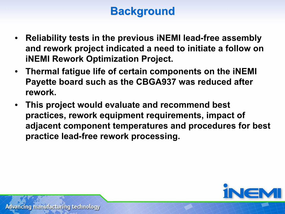
Phase 1 and 2 Results (See IPC/APEX 2008 Conf. Paper)Phase 1 and 2 Results (See IPC/APEX 2008 Conf. Paper)
• Variations in temperature repeatability across rework machines of the same model from 4 different machine suppliers.
• Average repeatability across the four machines in the two phases
to be +/-
5ºC.
Machine Repeatability Typical Worst CaseMachine A, Phase 1 +/- 5ºC TBDMachine B, Phase 1 +/- 3ºC TBDMachine C, Phase 1 +/- 7ºC TBDMachine D, Phase 1 +/- 1ºC TBD
Machine A, Phase 2 +/- 6ºC TBDMachine B, Phase 2 +/- 4ºC TBD Machine C, Phase 2 +/- 6ºC TBD Machine D, Phase 2 +/- 2ºC TBD
Thermocouple Repeatability +/- 1ºC +/- 2ºC

ConclusionsConclusions
• The repeatability tests for rework machines from four rework machine suppliers indicated an average repeatability of +/-
5ºC.• The rework machine temperature profiler was found to be fairly
effective in measuring temperature repeatability of the rework machine equipment.
• Work highlighted need to keep tighter tolerances in the form of periodic machine calibrations and temperature profiling to prevent component temperature issues during lead-free rework.

Future WorkFuture Work
• Phase 3 to assess the rework temperature repeatability of the same model of machine at an OEM/EMS manufacturing site.
• Assessments to include variations in airflow used for the rework
machine/ rework nozzle heights and the effect on temperature repeatability.
• Other areas which may influence temperature repeatability would be pre-
heater settings, power supply settings, nozzle design which may be considered in future testing.

Adjacent Component Group (HollyAdjacent Component Group (Holly--Dee Rubin) Dee Rubin)
INEMI Payette board: Spacing between components is 0.5 inch (13mm)
Previous FindingsBased on previous
J-STD-020 reflow parameters– To maintain peak package temperature <250°C required increased
bottom heater temperatures– Reworking the μBGAs with increased bottom heater temperatures
caused secondary reflow of the CBGA joints, and adversely impacted thermal fatigue life

232.9 245.4
223.0237.2
218.7237.3
211.3245.1
Joint
PCB
Bottom sideHeat EscapeHole
CBGA1
CBGA2
CBGA3
Reworked
TC LocationPeak Temp
(C) Reworked uBGA Joint 232.9Adjacent uBGA Joint 245.5CBGA 1 Joint 223.0CBGA 1 Bottom PCB 237.2CBGA 2 Joint 218.7CBGA 2 Bottom PCB 237.3CBGA 3 Joint 211.3CBGA 3 Bottom PCB 245.1
Joint and Package Temp Monitored Values
CBGA solder joints below and some above liquidous temperature
CBGACBGA--uBGAuBGA
Interaction StudyInteraction Study• Observations:
–Adjacent CBGA had liquidus temperatures (0.5 inch (13mm) away)–Thermal gradient across the CBGA package
(see table)

Adjacent Component GroupAdjacent Component Group
Solutions Explored– Heat shields– Rework profile re-
optimization
Objectives– Stay within J-STD-020D (260°C
peak) parameters when reworking components
– Ensure adjacent component joint temperatures remain below liquidus

Adjacent Component Temperature ResultsAdjacent Component Temperature Results
– Using the increased maximum allowed package temperature in J-
STD-20D, a rework profile was developed that kept the adjacent CBGA joints below the Sn3Ag0.5Cu liquidus temperature (217°C) in all cases.
– During rework of the U40 uBGA
component, the peak solder joint temperature of the CBGA (U27) was 204°C.
– Use of either an Aluminum or Ceramic heat shield (over the CBGA) lowered the joint temperatures on the CBGA by about 2°C
to 4°C.
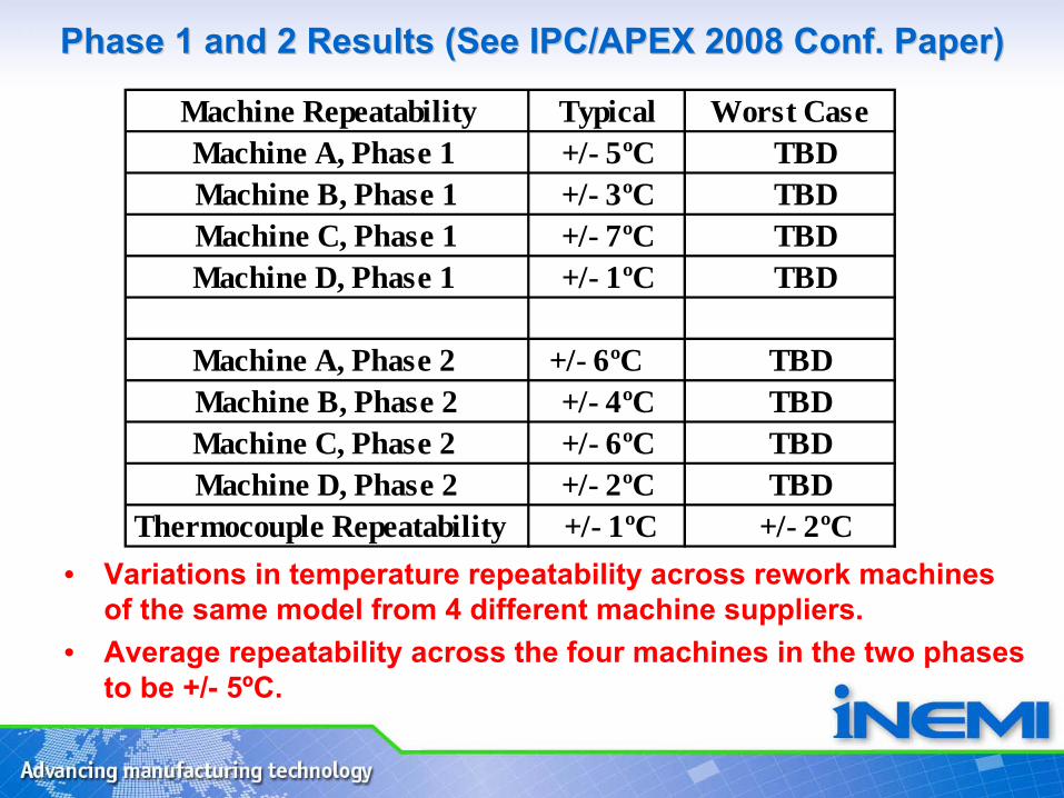
Representative LeadRepresentative Lead--free UBGA Rework Profile free UBGA Rework Profile (Leo Anderson, Flextronics)(Leo Anderson, Flextronics)
U40 Solder Joint peak temp.: 232 to 239°C. Time over 217C= 60 to 74 sec
U40 Component top peak temp.: 255°C. Time over 217C= 109 seconds

ConclusionsConclusions
• A lead-free rework profile was developed which kept the adjacent CBGA solder joints below liquidus (217°C) whilst keeping the reworked uBGA
component within J-STD-020D limits.• Found that heat shields (Al and Ceramic) helped to reduce the
temperature of the adjacent CBGA but not to a large extent (2°C
to 4°C)
Next StepsNext Steps
– Rework more boards for cross-sectional analysis and electrical testing to confirm that the adjacent CBGA components have not undergone partial melting/reflow.
– Further optimize rework process ready for reworking boards for ATC testing.

LeadLead--free BGA604 Socket Rework (Alan Donaldson)free BGA604 Socket Rework (Alan Donaldson)
• Create a lead-free board rework profile for the BGA 604 socket on the INEMI Payette board
• Rework the sockets and verify they pass electrical test
• Measurement of stand-off height

INEMI Payette BGA604 Socket Profile Board SetupINEMI Payette BGA604 Socket Profile Board Setup
TC1-4 Socket Outer Corner Solder JointsTC5-6 Socket Center Solder JointsTC7-10 Socket Top BodyTC11-12 Socket Body Top Pin HolesTC13 CAF1 Board Location

• Soak Time (150-
217°C) = 124 to 139 sec• Time above liquidus (217°C) for solder joints = 137sec to 185 sec
BGA 604 Socket Rework Temperature ProfileBGA 604 Socket Rework Temperature Profile

•Flux activation time is above target of 100 second and falling
rate ramp is slow•Time above liquidus (217°C) is on the high side (up to 186 sec)
Thermocouple Solder Joint Description
Rising Ramp Rate/°C/sec
Flux Activation
Time (150°C to 217°C)
Critical Ramp Rate (205°C to 215°C) °C/sec
Socket Peak Temperature
(230°C to 250°C)
Socket Time Above
Liquidus (40- 200sec)
Falling Ramp Rate/ °C/sec
TC1 Pin 1 Outer Corner
0.5 139sec 0.5 242°C 186sec - 0.2
TC2 Outer Corner 0.6 124sec 0.5 243°C 180sec - 0.3TC3 Outer Corner 0.5 132sec 0.4 235°C 137sec - 0.2TC4 Outer Corner 0.5 132sec 0.5 236°C 159sec - 0.2
TC5 Center 0.5 132sec 0.5 236°C 182sec - 0.1TC6 Center 0.5 138sec 0.5 238°C 185sec - 0.2
BGA 604 Socket Rework Temperature ProfileBGA 604 Socket Rework Temperature Profile

BGA604 Socket Rework Temperature Profile (continued)BGA604 Socket Rework Temperature Profile (continued)
– Socket body below 260°C (257°C)– Part of the CAF1 board area is at or above the reflow temperature (217°C)
• All the area within 0.7 inch of the BGA604 socket– Time above liquidus for sockets are very long (up to 186 sec) because the heat
gets trapped in the center• The BGA rework machine had a bottom heater that is 14 X 21inch
– This heater size makes it hard to heat up and cool down quickly– Compare this with J-STD-020D standard which indicates Time above liquidus for a
component should be between 60 and 150 seconds– All four reworked boards passed electrical resistance test
Thermocouple Description Socket Body Temperature (260°C Maximum)
Maximum Board Temperature
TC10 Socket Top Body 257°C XTC11 Socket Top Body Pin
Hole239°C X
TC13 CAF1 Board Location X 217°C

604 Socket Stand604 Socket Stand--off Resultsoff Results
–Board 22 cross-section shows that the socket sinks chips down on the A31 & AE2 corners
• The A31 corner stand-off is approximately 2.5mils lower• The AE2 corner stand-off is approximately 3.5mils lower
–Board 24 cross-section shows only the AD1 corner to have a larger collapse than all other measurements
• The AD1 corner stand-off is approximately 4mils lower
–This is a fairly common observation in Lead-free BGA socket rework

SummarySummary
– Flux activation time and falling ramp rate exceeds specification• The BGA rework machine has large bottom heater which makes it hard to heat up
and cool down quickly
–Time above liquidus for sockets are very long (up to 186sec)• Compare this with J-STD-020D standard (Time above liquidus for a component
should be between 60 and 150 seconds)
–Reworked BGA socket sinks down on the certain corners• This is a fairly common observation in Lead-free BGA socket rework
–Reworked BGA socket passed electrical measurements

Next StepsNext Steps
– Cross-sectional analysis for reworked boards for intermetallic measurements
– Further optimize rework process ready for reworking boards for ATC testing.
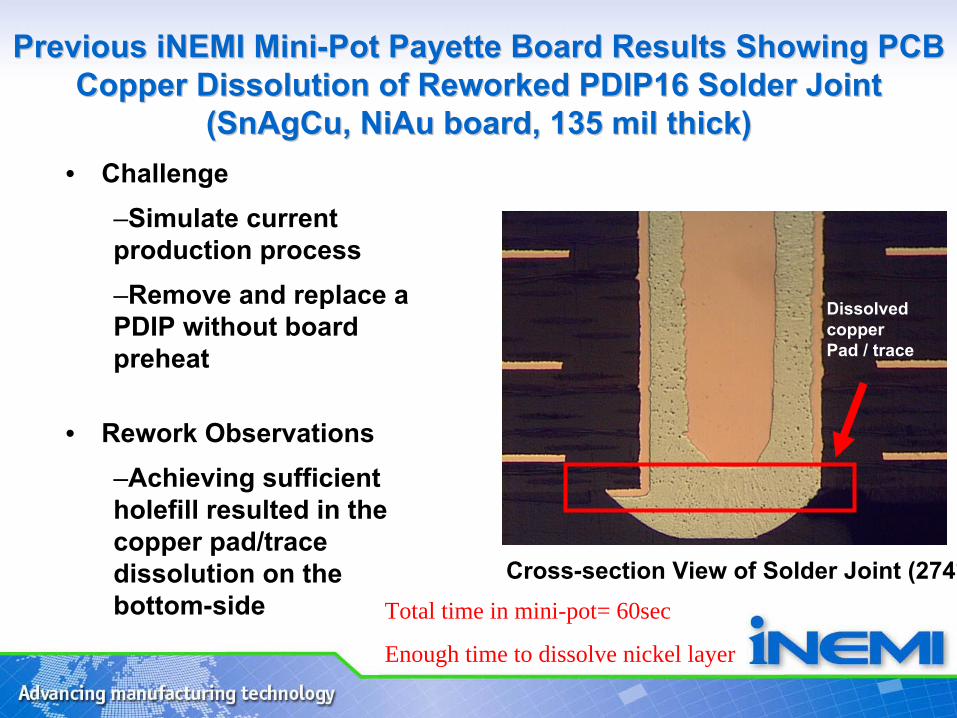
Cross-section View of Solder Joint (274°
Dissolvedcopper Pad / trace
Total time in mini-pot= 60sec
Enough time to dissolve nickel layer
Previous iNEMI MiniPrevious iNEMI Mini--Pot Payette Board Results Showing PCB Pot Payette Board Results Showing PCB Copper Dissolution of Reworked PDIP16 Solder Joint Copper Dissolution of Reworked PDIP16 Solder Joint
(SnAgCu, (SnAgCu, NiAuNiAu
board, 135 mil thick)board, 135 mil thick)• Challenge
–Simulate current production process –Remove and replace a PDIP without board preheat
• Rework Observations–Achieving sufficient holefill
resulted in the copper pad/trace dissolution on the bottom-side

MiniMini--pot Rework (Phase 1)pot Rework (Phase 1)
• Generally speaking there was evidence of reduced copper dissolution when reworking 1st
pass SnAgCu wave soldered boards with Sn-Cu-Ni compared with rework using SnAgCu.
• Further optimization and development work will be done on the iNEMI Payette Board which is 125mil thick (OSP coated) with concentration on the DIMM 278 connector and DIP16 component (Phase 2)

PTH Rework Locations (Phase 2)PTH Rework Locations (Phase 2)
2 DIMM278 Connectors3 PDIP16 Components
1X rework Sn-Cu-Ni
DIP16
2X rework Sn-Cu-Ni
DIP16
1X rework SAC305 DIP16
Note: 1st pass wave using Sn3Ag0.5Cu
1X rework Sn-Cu-Ni DIMM278

DIMM Connector Rework Thermocouple DIMM Connector Rework Thermocouple Locations (Phase 2)Locations (Phase 2)
• 3 Thermocouple Locations, topside lead• Edge and center lead locations• Monitor temperature to understand contact
time required for reflow• Also used to profile preheat profile• Dummy copper traces on bottom side to
measure copper dissolution

Phase 3 PTH Rework Matrix (ATC testing)Phase 3 PTH Rework Matrix (ATC testing)
PTH Rework Objectives:• Validate process and
reliability of reworking a Sn3Ag0.5Cu joint with Sn-Cu-
Ni alloy (mixed case)
• Validate process and reliability (ATC) of reworking Sn3Ag0.5Cu joint with Sn3Ag0.5Cu alloy
• Measure levels of Cu dissolution for both types of reworked joints
• 1X rework on DIMM278• 1X and 2X rework on DIP16

Next StepsNext Steps
– Develop rework process for DIP16 with SnAgCu and SnCuNi
alloys– Develop rework process for DIMM278 components with SnCuNi– Cross-sectional analysis for reworked boards to measure copper
dissolution and solder joint integrity– Further optimize rework process ready for reworking boards for
ATC testing.

NEMI Rework Optimization Project Next StepsNEMI Rework Optimization Project Next Steps
• Group’s work has concentrated on – Mini-Pot rework optimization – Rework Machine Temperature Repeatability– Adjacent component temperatures during rework – BGA socket
Optimize process for Mini-pot rework, adjacent component and BGA socket rework before ATC testing of reworked boards

AcknowledgementsAcknowledgements
• The main group and sub-group chairs would like to thank the INEMI rework project team for their input and efforts into this work.