Embed Size (px)
Citation preview
IDX-OM-K031-E
Initial issue: September, 2006 5th edition: July, 2011
PRODUCT NAME
Refrigerated Air Dryer
MODEL / Series
IDU8E-10-C,K,L,R,S,T IDU8E-20-C,K,L,R,S,T IDU11E-10-C,K,L,M,R,S,T IDU11E-20-C,K,L,M,R,T IDU15E-10-C,K,M,R,S,T IDU15E-20-C,K,M,R,T
IDU8E-23-C,K,L,R,T,V IDU11E-23-C,K,L,R,T,V IDU15E-23-C,K,R,T,V
Please read this manual prior of using the air dryer. Keep the manual readily available for reference.
© 2011 SMC CORPORATION All Rights Reserved

Dear Customers Thank you for selecting SMC Refrigerated Air Dryer. This operation manual must be read and understood thoroughly before using the product. It provides all essential information pertaining to safety, as well as, maximizing product efficiency in order to extend the life of the product. In addition, it is strongly recommended that you follow all the safety guidelines and regulations set forth by the local government agency for proper installation and usage. This manual explains about installation and trial operation of the product. These tasks should be performed only by individuals with the proper training and have a good understanding of the air dryer. There is no production amends or financial compensation due to dryers trouble. This manual contains confidential information proprietary to SMC. It must not be reproduced or disclosed to others, or used in any other way, in part or in whole, except as authorized in writing by SMC.
Caution: Please understand that the contents of this operation manual are subjected to change without prior notice.

Table of Contents
Table of Contents - 1
Table of Contents
To Customers Chapter i Safety Instructions
i - 1 Warning: Before Using Air Dryer.........................................................i - 1 i - 1 - 1 Hazard, Warning, and Caution Used in This Manual ...........i - 1 i - 2 Danger Classifications/Position of Hazard warning Label........i - 2 i - 2 - 1 Danger Classifications ..........................................................i - 2 i - 2 - 2 Hazard of Electricity ..............................................................i - 3 i - 2 - 3 Hazard of Hot Surface ...........................................................i - 3 i - 2 - 4 Hazard of Rotating Fan Motor ...............................................i - 3 i - 2 - 5 Danger of Compressed Air Circuit .......................................i - 3 i - 2 - 6 Positions of Hazard Warning Label ......................................i - 4 i - 2 - 7 Hazard of Refrigerant ............................................................i - 5 i - 2 - 8 Cautions about Usage...........................................................i - 6 i - 2 - 9 Other Label ............................................................................i - 6 i – 3 Disposal .......................................................................................................i – 7 i – 4 Limited warranty and Disclaimer / Compliance Requirements ......i - 8
Chapter 1 Parts Name and Functions 1 - 1 Parts Names and Functions ................................................................ 1 - 1
Chapter 2 Transportation / Installation 2 - 1 Transportation .......................................................................................... 2 - 1 2 - 2 Installation.................................................................................................. 2 - 2 2 - 2 - 1 Location ................................................................................2 - 2 2 - 2 - 2 Anchorage.............................................................................2 - 2 2 - 2 - 3 Air piping...............................................................................2 - 2 2 - 2 - 4 Drain Tube.............................................................................2 - 3 2 - 2 - 5 Electric Wiring ......................................................................2 - 4 2 - 3 Cautions about reinstallation ............................................................. 2 - 5
Chapter 3 Operation / Shutdown 3 - 1 Check points before operation .......................................................... 3 - 1 3 - 2 Operation.................................................................................................... 3 - 1 3 - 3 Shutdown ................................................................................................... 3 - 2 3 - 4 Cautions about restart........................................................................... 3 - 2 3 - 5 Check points before restart................................................................. 3 - 2 3 - 6 Precautions for long-term non-operation ...................................... 3 - 2
Chapter 4 Maintenance 4 - 1 Daily inspection ....................................................................................... 4 - 1 4 - 2 Periodical Maintenance......................................................................... 4 - 1 4 - 2 - 1 Cleaning of ventilation grille (suction grille) .......................4 - 1 4 - 2 - 2 Service parts .........................................................................4 - 1 4 - 2 - 3 Cleaning of the case assembly............................................4 - 1 4 - 2 - 4 Replacement of case assembly ...........................................4 - 2
Chapter 5 Troubleshooting............................................................................................ 5 - 1 Chapter 6 References
6 - 1 Specifications ........................................................................................... 6 - 1

Table of Contents
Table of Contents - 2
6 - 2 Dimensions................................................................................................ 6 - 2 6 - 3 Electrical Circuit ...................................................................................... 6 - 3 6 - 4 Compressed Air and Refrigerant Circuit / Operation Principles .....6 - 5 6 - 5 How to order.............................................................................................. 6 - 6
Chapter 7 Option Specification C 7 - 1 Safety instructions.................................................................................. 7 - 1 7 - 2 Precautions for the installation and handling of the product .........7 - 1 7 - 3 Specifications ........................................................................................... 7 - 1
Chapter 8 Specification for Option K 8 - 1 Safety instructions.................................................................................. 8 - 1 8 - 2 Specifications ........................................................................................... 8 - 2
Chapter 9 Specification for Option L 9 - 1 Safety instructions.................................................................................. 9 - 1 9 - 2 Specification.............................................................................................. 9 - 1 9 - 3 Specification of heavy duty auto drain (ADH4000-04). ............. 9 - 2 9 - 4 Installation of heavy duty auto drain ............................................... 9 - 2 9 - 5 Maintenance .............................................................................................. 9 - 2
Chapter 10 Specification for Option M 10 - 1 Safety instructions................................................................................ 10 - 1 10 - 2 Specification............................................................................................ 10 - 2 10 - 3 Installation of the motor-type auto drain...................................... 10 - 3
Chapter 11 Specification for Option R 11 - 1 Safety instructions.................................................................................11 - 1 11 - 2 Specifications of the GFCI ..................................................................11 - 2 11 - 3 How to connect the power supply...................................................11 - 2
Chapter 12 Specification for Option S 12 - 1 Safety instructions................................................................................ 12 - 1 12 - 2 Specifications ......................................................................................... 12 - 1 12 - 3 How to connect the power supply cable...................................... 12 - 1 12 - 4 Electric circuit......................................................................................... 12 - 2
Chapter 13 Specification for Option T 13 - 1 Safety instructions................................................................................ 13 - 1 13 - 2 Specifications ......................................................................................... 13 - 1 13 - 3 Remote operation.................................................................................. 13 - 2 13 - 4 How to connect the power supply and signal cable................ 13 - 2 13 - 5 Electric circuit......................................................................................... 13 - 3
Chapter 14 Specification for Option V 14 - 1 Safety instructions................................................................................ 14 - 1 14 - 2 Specifications ......................................................................................... 14 - 2 14 - 3 How to perform maintenance ........................................................... 14 - 2
Chapter 15 Service Record 15 - 1 Service Record ....................................................................................... 15 - 1

i Safety Instructions
i Safety Instructions
Be sure to read and comprehend important cautionary notifications in this operation manual before use
Do not operate the product without the cover panel.
i-1 Warning: Before Using Air Dryer In this chapter, the stated contents are especially about safety.
This Air Dryer is installed downstream of the air compressor to remove moisture. The manufacturer is not responsible for any misuses or misapplications.
This air dryer operates with high voltage and hot surfaces during operation. In addition, this air dryer has high speed rotating fan and motor, which can cause serious injury upon accidental contact. It is advised that you contact the factory or SMC authorized dealer for spare parts or other servicing needs.
We strongly recommend that any one who is working with this air dryer need to read and understand the instructions in this manual beforehand. Often, it’s necessary for the people involved, to receive training in order to address the issues of safety and proper application.
When short period power shortage (including instantly recovered shortage) is recovered, it may take a longer starting period than usual starting or may not start due to the protective devices. In this case, turn off the ON-OFF switch with lamp on dryer panel and wait 3 minutes. After this step, turn on the switch to restart. Whenever open the cover panel of this unit, do not miss to turn off the ON-OFF switch with lamp, because dryer may start itself when the power supply is recovered.
Connections to a power source where the product is exposed to transient stresses exceeding overvoltage category II (as defined in IEC60664-1). Only connect to TN-S power distr ibution systems with N conductively connected to PE. i-1-1 Hazard, Warning, and Caution Used in This Manual
This product is designed with the first priority on safety. However, there are some inherent risks that cannot be eliminated. This manual classifies these risks into the following three categories according to the severity: DANGER, WARNING and CAUTION. Read the warning statements carefully and thoroughly understand them before operating or performing maintenance on the unit.
DANGER “DANGER” indicates that there is an imminence hazard that will cause serious injury or death if not avoided.
WARNING
“WARNING” indicates that there is a hazard that may cause serious injury or death if not avoided.
CAUTION
“CAUTION” indicates that there is a hazard that may cause minor injury.
i - 1

i Safety Instructions
i-2 Danger Classifications & Position of Hazard warning Labels To help you recognize the hazards, the unit utilizes special graphics to indicate different hazards. Confirm the contents of the hazards and the location of the labels before operation.
Warning
• Only properly trained, qualified personnel are allowed to perform tasks such as: Operation, installation, relocation of product and maintenance works.
• Should any problem occurs, address it according to instruction in this manual. • Identify problems following the guidelines in Chapter 5 for Troubleshooting before
proceed with maintenance works. • The product should not be turn on in the event of any problems.
When the product gets out of order, shutdown immediately, and contact for service
i-2-1 Danger Classifications
Specific danger classification of this product is as follows. Hazard of Electricity Since this product operates with high voltage, there is the danger of electric shock. This special symbol is used, along with key words: “CAUTION”, “WARNING” or “DANGER”, on the product and in this manual. Hazard of Hot Surface Since this product becomes hot while running, there is the danger of burn injury. This special symbol is used, along with key words: “CAUTION”, “WARNING” or “DANGER”, on the product and in this manual. Hazard of Rotor Since this product has parts that rotate at high speed while running, there is the danger of bodily injury. This special symbol is used, along with key words: “CAUTION”, “WARNING” or “DANGER”, on the product and in this manual.
i - 2

i Safety Instructions
i-2-2 Hazard of Electricity
Warning
Inside of this product, there is a power-supplying section with high voltage separated by the cover panel. Do not operate the product with the cover panel off.
i-2-3 Hazard of Hot Surface Warning
Since this product has parts that become hot during operation, there is the danger of burn-associated injuries. These parts remain hot even after power is off. Wait until the unit has cooled down before touching.
i-2-4 Hazard of Rotating Fan Motor Warning
Since this product has parts that rotate during operation, there is the danger of injury resulting from direct contact. The fan and rotor will start/stop automatically. Thus, do not work on them when power is on.
i-2-5 Danger of Compressed Air Circuit
Warning
Before replacing or cleaning parts, be sure to relief the pressure remained inside of the product until the gauge indicates “0”. High pressure can propel object at high velocity and cause injury.
i - 3

i Safety Instructions
i-2-6 Positions of Danger Warning Label
Warning
Read with caution and pay attention to the notations of danger warning labels. Do not remove or rub danger warning labels. Confirm the positions of danger warning labels.
Front
WARNING 警告!
1 Remove panels for maintenance only.2 Never insert anything into product to ensure safety.3 Cut power prior to maintenance to prevent electric shock.4 Settle product to room temp.before main- tenance toprevent burn or frostbite.5 Ensure zero air pressure before replacing parts.
1 点検以外はパネルを取り外さないこと。
2 回転物があるので指、棒状の物を差し
込まないこと。
3 感電の恐れがあるので、点検の前には電源を
切ること。
4 火傷の恐れがあるので、点検の前には装置を
常温にすること。
5 部品交換の前には必ず、空気圧力を"0"に
すること。
!
i - 4

i Safety Instructions
i-2-7 Hazard of Refrigerant
Caution
This product uses Fluorocarbon (HFC) as a refrigerant. It is strictly forbidden to emit Fluorocarbon into the atmosphere. Before you repair the refrigerant circuit, you should collect the refrigerant with proper evacuation system. The collected refrigerant should be properly recycled by qualified agency. Only personnel with proper credential are allowed to handle refrigerant. Only properly trained qualified personnel are allowed to remove the cover panel of the product. The quantity and the type of Fluorocarbon are mentioned on the specification label. See Page i - 6.
Fluorocarbon Collection and Destruction Law in Japanフロン回収破壊法第一種特定製品
This product uses Fluorocarbon (HFC) as a refrigerant.1 It is strictly forbidden to emit Fluorocarbon to the atmosphere.2 When disposing this product, Fluorocarbon must be collected in an appropriate manner.3 The kind of Fluorocarbon and the amount used in this product is prited on the name label.
この製品には冷媒として、
フロン類(HFC)が使われています。
1 フロン類をみだりに大気中に放出することは
禁じられています。
2 この製品を廃棄する場合には、フロン類の回収が
必要です。
3 フロン類の種類及び数量は、型式銘板に記載
されています。
Front
i - 5

i Safety Instructions
i-2-8 Cautions about Usage
Warning
Please follow the instructions on all warning labels. Do not remove or deface warning labels, and confirm the location of warning labels.
i-2-9 Other Label
Front
Contents MODEL: Model VOLTAGE: Power supply voltage (frequency) RUNNING CURRENT: Running current REFRIGERANT: Type of refrigerant (amount) WEIGHT: Weight MAX.PRESS: Maximum operating pressureSERIAL No.: Serial No. MAKER: Maker MADE IN: Country of manufacture
Specification Label
AIR DRYERMODEL
VOLTAGERUNNING CURRENTREFRIGERANTWEIGHT MAX.PRESS.SERIAL No.MAKER
MADE IN
CAUTION 注意!
1 Read manual before operation.2 Ensure vantilation and maintenance space.3 Keep water away from the product.4 Secure In / Out connector with spanner during piping.5 Wait 3 minutes before restart.6 Ensure Running Condition / Evaporating Temp. in green zone.
1 ご使用前に必ず取扱説明書を読んでください。
2 通風、メンテナンススペースを確保して
ください。
3 雨や水滴がかからないようにしてください。
4 IN/OUTポートをスパナで固定して
配管してください。
5 再起動は運転停止3分後に行ってください。
6 RUNNING CONDIT ION・蒸発温度計は
グリーン帯で使用してください。
Front
i - 6
i Safety Instructions
i-3 Disposal
When you dispose of the product, you should collect the refrigerant and the refrigerant oil inside the refrigerant circuit.
Caution This product contains Fluorocarbon HFC. It is strictly forbidden to emit Fluorocarbon into the atmosphere. Before you repair the refrigerant circuit, you should collect the refrigerant with proper evacuation system. The collected refrigerant should be properly recycled by qualified agency. Only personnel with proper credential are allowed to handle refrigerant. Only properly trained and qualified personnel are allowed to remove the cover panel of the product. The quantity and the type of Fluorocarbon are mentioned on the specification label. See Page i - 6.
Caution
Dispose of the refrigerant and refrigerant oil according to the regulation of local government. Only personnel with proper credential are allowed to collect refrigerant and refrigerant oil. Only properly trained and qualified personnel are allowed to remove the cover panel of the product. For any questions, please contact our factory or SMC authorized dealers.
i - 7

i Safety Instructions
i – 4 Limited warranty and Disclaimer / Compliance Requirements The product used subject to the following “Limited warranty and Disclaimer“ and “Compliance Requirements. Read and accept them before using the product.
Limited warranty and Disclaimer 1. The warranty period of the product is 1 year in service or 1.5 years after the product is delivered.
Also, the product may have specified durability, running distance or replacement parts. Please consult your nearest sales branch.
2. For any failure or damage reported within the warranty period which is clearly our responsibility, a replacement product or necessary parts will be provided. This limited warranty applies only to our product independently, and not to any other damage incurred due to the failure of the product.
3. Prior to using SMC products, please read and understand the warranty terms and disclaimers noted in the specified catalog for the particular products.
Compliance Requirements 1. The use of SMC products with production equipment for the manufacture of weapons of mass
destruction (WMD) or other weapon is strictly prohibited. 2. The exports of SMC products or technology from one country to another are govemed by the relevant
security laws and regulation of the countries involved in the transaction. Prior to the shipment of a SMC product of a SMC product to another country, assure that all local rules goveming that export are known and followed.
Caution The Product is provided use in manufacturing industries. The product herein described is basically provided for peaceful use in manufacturing industries. If considering using the product in other industries, consult SMC beforehand and exchange specifications or a contact if necessary. If anything is unclear, contact your nearest sales branch.
i - 8

1 Name and Functions Parts
1 Parts Name and Functions
1-1 Parts Name and Functions • IDU8E to 15E
Front
The lamp is continuously ON during normal operation.
Evaporation Thermometer Indicates the evaporating temperature of refrigerant on low-pressure side. During normal operation, the indicator remains in the green zone.
Panel Lock (2x2) Another two are on opposite side
Right Side Ventilation Grille (Outlet)
Waste heat will be exhausted as hot air by the fan motor. Do not block with wall and so on.
Inspection Grille Confirm the discharge of drain from this grille once a day.
Drain Tube Discharges drain.
Switch with Lamp
View with Front Panel removed
Do not remove the insulation on the auto drain.
Auto Drain
1 - 1

1 Name and Functions Parts
• IDU8E to 15E-10 (AC100V)
Front
Air Outlet (OUT)
Screw for the Earth Connect the earth to this screw
Power Cord Insert the plug to an outlet for exclusive use of AC100V.
Air Inlet (IN)
Panel Lock (2x2) Another two are on opposite side
Left Side Ventilation Grille (Inlet) Breathe in cooling air from this grill. Do not bung up with wall and so on.
・ IDU8E to 15E-20 (AC200V) ・ IDU8E to 15E-23 (AC230V)
Rear Panel You can see the terminal block when you
remove this cover. Connect the power
cable through the membrane grommet.
Rubber Grommet
(Width 6.5mm and below) (Screw head dimension: 0.25” (6.5mm)
Customer Connection Side Terminal Connecting Screw: M3 Ring terminals: 1.25-3
L N PE ( )
Power cable inlet
Front
1 - 2
2 Transportation / Installation
2 Transportation / Installation
Warning
• Only properly trained, qualified personnel are allowed to perform tasks such as: Operation, installation, relocation of product and maintenance works.
• Strongly recommend to prepare the spare dryer when applying the dryer for
important product or system.
2 - 1 Transportation
When you transport the product, you should follow the instructions below: • You should lift the product from the base surface with careful attention to prevent tipping over. • Do not lay the product sideways, or you will damage the product. • Do not suspend the product from the ceiling or hang from the wall. • Do not transport the product with any part such as an air filter mounted on the fittings at the air inlet or
outlet port of the product. If it is unavoidable to transport the product with such a part mounted, support the mounted part with a bracket to prevent the product from being affected by vibration during transportation.
Warning This product is a heavy object and will give a danger when transported. Be sure to keep the above instructions. The IDU8E to 15E weigh 44 to 71kg. Three people for the IDU8E and 11E and four people for IDU15E, or a tool like a fork lift must be prepared.
2 - 1

2 Transportation / Installation
2 - 2 Installation
2 - 2 - 1 Location The product should not be used or stored in the following conditions: Those conditions will cause not only malfunction but also failures.
• Environment where the product is exposed to
rainwater, moisture, salt water or oil.
• Locations where the product is exposed to dust
or particles
• Locations where the product is exposed to
flammable, combustible or explosive fumes.
• Locations where the product is exposed to
corrosive gas or solvent.
• Locations where the product is exposed to
direct sunlight or radiated heat.
• Locations where ambient temperature is
beyond following range:
• On-stream: 2 to 40oC
• Storage: 0 to 50oC (when there is no drain
water inside of the piping)
• Locations where temperature changes rapidly.
• Locations where strong electromagnetic noise
is generated.
• Circumstances where static electricity is
produced or discharged through the body of the
product
• Locations where strong high frequency shock
wave is generated
• Locations where danger of thunder is apparent. • Locations where loading on vehicles, marine
vessels, and so on • Locations where altitude is higher than 2,000
meters • Circumstances where strong vibration or impact
are transmitted. • Circumstances where too much force and weight
are put on the body of the product that causes it to
deform.
• Circumstances where not enough clearance spaces to do maintenance
• Spaces needed for maintenance • Front : 600mm • Rear : 600mm • Top : 600mm • ight : 600mm • Left : 600mm • Locations where ventilation grille of the product can
be blocked.
• Locations where the dryer could intake warm air (for
example from a compressor or other dryers).
2 - 2 - 2 Anchorage • The air dryer should be installed on a vibration-free, stable, horizontal flat surface.
• Refer to “Chapter6 6-2 Dimensions” for the dimensions.
• IDU8E~15E should be bolted by anchor bolts to prevent falling. We recommend the anchor bolt sets that
we are selling separately as accessories. 2 - 2 - 3 Air piping • Connection to the inlet and outlet of compressed air should be made removable by using union and so on.
• Pressing the hexagonal fitting with screw wrench and so on, connect the air piping fittings to the body.
• When mounting any part such as an air filter on the fitting at the compressed air inlet or outlet port, support the
part to prevent excessive force from being applied to the product.
• Be careful not to let the vibration of the air compressor transmit.
2 - 2

2 Transportation / Installation
• If the temperature of compressed air on the inlet side is higher than 50oC, place an aftercooler after the air
compressor. Or, make the temperature of the place where the air compressor is installed lower than 50oC.
• Flash the piping sufficiently in order to avoid any foreign substances such as dust, sealing tape, liquid gasket, etc.
when piping before piping connection.Foreign substances in the piping can cause cooling failure or drainage
failure.
• Use pipes and fittings that have enough endurance against the operating pressure and temperature. And
connect it firmly to prevent air leakage.
• Provide bypass piping to make it possible to do maintenance without stopping the air compressor. We recommend the bypass piping sets that
we are selling separately as accessories.
The bypass piping sets 2 - 2 - 4 Drain Tube • A polyurethane tube (10mm) O.D. is attached to the auto drain. The end of the tube is open to atmosphere to let
drain flow through the tube into a collector or drain pipe.
• The compressed air is used to push out the drain periodically. Fix the outlet end of the tube in order to prevent
whipping action during discharge.
• Install the drain tube in such a way so that no drain is trapped.
• During installation, make sure the dryer does not sit on the drain tube which is at the bottom of the unit. Be
careful to avoid the dryer from crushing the tube during installation.
Warning
To handle drain discharge, follow the safety guidelines such as wearing protective goggles, apron, and gloves. In case that oil gets mixed in the wastewater discharged from the auto drain, the liquid would be considered as toxic waste and treatment is necessary in accordance with local regulations.
2 - 3

2 Transportation / Installation
2 - 2 - 5 Electric Wiring
Warning Only properly trained and qualified personnel are allowed to perform wiring work. ・ Before wiring, you must disconnect the power. Do not work under any energized
conditions. ・ Supply power from a stable source that is free from the effect of surge. ・ Ensure that a Ground Fault Circuit Interrupter(GFCI) with appropriate capacity for earth
leakage and load is used in the power supply of the product to prevent electrical shock and burnout of the compressor motor. See “6-1 List of specifications” for details.
・ Supply power of the product should meet the specifications on page 6-1. ・ The product must be grounded for safety. ・ Do not connect ground wire to a water pipe, a gas pipe, or a lightening rod. ・ Do not plug too many leads into a single socket. ・ Circuit breaker must be properly selected to meet safety standard of local regulations. ・ Always be sure to connect the protective conductor first, disconnect it last in respect
to the other connections. ・ Be sure that the protective conductor has some additional length in respect to the live
conductors, so that it is not subject to mechanical stresses. ・ Be sure to install the circuit breaker correctly so that it disconnects all live conductors
and so that the operating handle can be easily accessible.
There are two methods depends on model (specified power).
IDU8E-10 ~ 15E-10 (100V specified) • Insert the power plug into an outlet of AC100V.
Install a Ground Fault Circuit Interrupter(GFCI) to the power supply (sensitivity of leak current 30mA and rated current 10A).).(Prepare by yourself)
• Do not extend the power cable using power strip and so on. That causes decrease of the voltage and the product cannot be operated.
IDU8E-20 ~ 15E-20 (200V specified), IDU8E-23 ~ 15E-23 (230V specified) • Remove the terminal block cover or the rear cover in the rear of the product, and connect the power
(AC200V or AC230V) to the terminal block. • Install a Ground Fault Circuit Interrupter(GFCI) to the power supply (IDU8E, 11E : sensitivity of leak
current: 30mA and below, Rated current 5A , IDU15E : sensitivity of leak current: 30mA and below, Rated current 10A).(Prepare by yourself)
Specification of power cable
Prepare following power cable. Power cable: 1.25mm2(16AWG), Three-cores (including the ground cable), External diameter: about 8 to 12mm. Additional length of about 0.1m (4in) is needed to wire inside of the product.
Length of the power cable The maximum length of the power cable should be no more than 30m.
Connecting to the power supply • Connect the power cable and the ground to the terminal block. Make sure to use the ring terminals
for M3 screws. • Applicable crimped terminal: 1.25-3 (Width: 6.5mm and below)
2 - 4

2 Transportation / Installation
Wiring procedure • Remove the terminal block cover or the rear panel. • Insert the cord through the rubber grommet and connect it to the terminal block (refer to the label on
the terminal block). M3 screw tightening torque: 0.63Nm • During wiring work, do not touch other sections except terminal block. • Re-attach the cover or real panel after wiring is done. (M4 screw tightening torque: 1.5Nm)
2 - 3 Cautions for Reinstallation
Caution
Only properly trained, qualified personnel are allowed to perform reinstallation.
If the product is moved and reinstalled in another place after some trial operations, the following instructions must be followed as well as procedures in Chapter 2.
Removing the power cable
Disconnect the power source before removing the power cable.
Warning
Only properly trained, qualified personnel are allowed to perform wiring.Disconnect the power source before wiring. Do not work under energized condition
Disconnecting air pipes
Warning
Only properly trained, qualified personnel are allowed to perform piping works. Separate the compressor from the product before disconnecting the air pipe. Do not disconnect any piping when there is residual air pressure inside of the pipe.
• Remove the seal tape completely after removing the piping. Loose seal tape can clog up the system. Releasing residual pressure
• Bypass valve should open even after the dryer has been removed. • Close the compressed air inlet and outlet valve. • Unscrew the front panel screws (in 2 places) and remove the front panel. • Open the auto drain residual pressure release valve to release air pressure inside the product. Refer to the
figure at right. Case Assembly
The ramainder depressure cock.※It opens when turning in the drection og the arrow of figure.
2 - 5
3 Operation / Shutdown
3 Operation / Shutdown
Caution
Only properly trained and qualified personnel are allowed to perform operation/shutdown of the product.
3-1 Check points before operation Before trial run, check the following points:
• Installed Conditions: By visual inspection , check that the product is level. Model IDU8E to 15E, make sure the product is tied down with anchor bolts. Do not place heavy objects on the top of the product. Make sure piping does not add weight to the product.
• Power cord, and the ground should be connected firmly. • Drain tube should be connected correctly.
• Make sure the piping for compressed air is connected correctly.
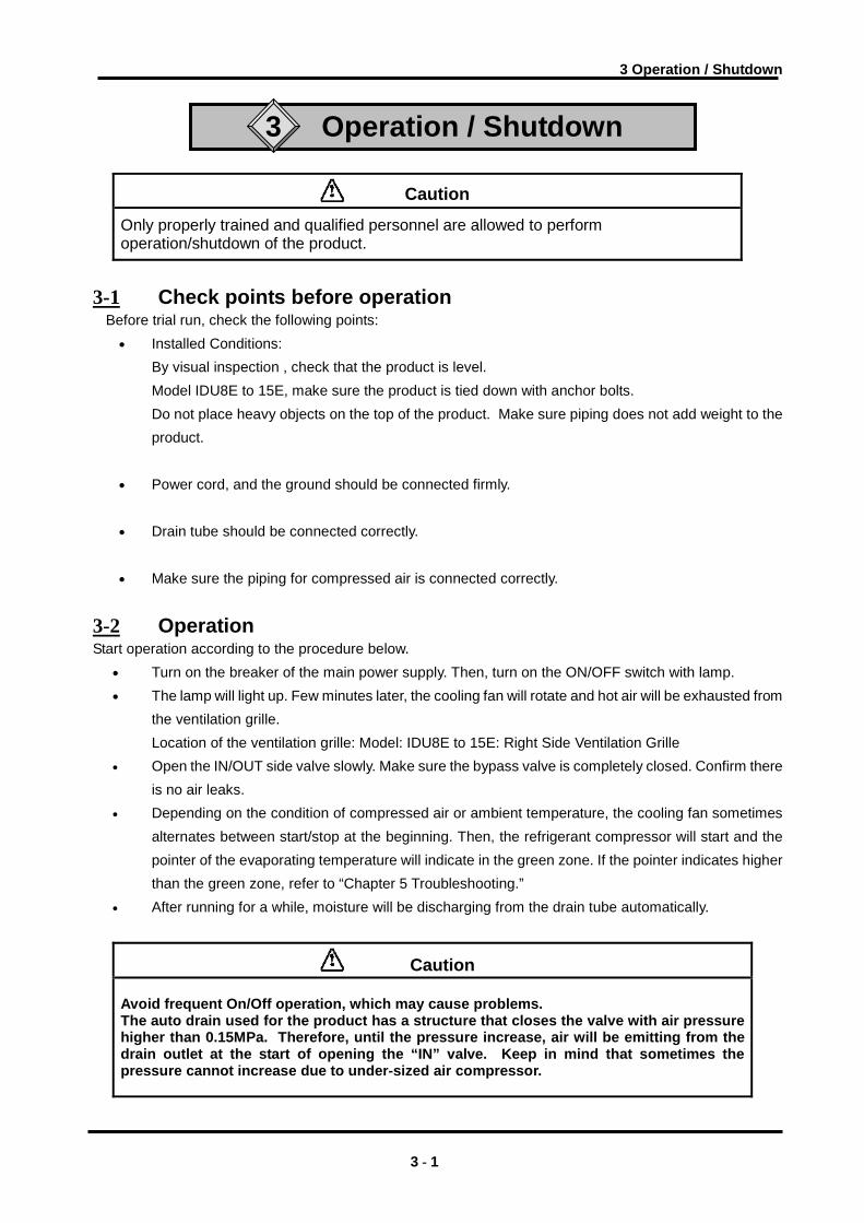
3-2 Operation Start operation according to the procedure below.
• Turn on the breaker of the main power supply. Then, turn on the ON/OFF switch with lamp. • The lamp will light up. Few minutes later, the cooling fan will rotate and hot air will be exhausted from
the ventilation grille. Location of the ventilation grille: Model: IDU8E to 15E: Right Side Ventilation Grille
• Open the IN/OUT side valve slowly. Make sure the bypass valve is completely closed. Confirm there is no air leaks.
• Depending on the condition of compressed air or ambient temperature, the cooling fan sometimes alternates between start/stop at the beginning. Then, the refrigerant compressor will start and the pointer of the evaporating temperature will indicate in the green zone. If the pointer indicates higher than the green zone, refer to “Chapter 5 Troubleshooting.”
• After running for a while, moisture will be discharging from the drain tube automatically.
Caution
Avoid frequent On/Off operation, which may cause problems. The auto drain used for the product has a structure that closes the valve with air pressure higher than 0.15MPa. Therefore, until the pressure increase, air will be emitting from the drain outlet at the start of opening the “IN” valve. Keep in mind that sometimes the pressure cannot increase due to under-sized air compressor.
3 - 1

3 Operation / Shutdown
3-3 Shutdown • Turn off the ON/OFF switch with lamp. • The lamp will go out and then, the operation will stop. Depending on the condition of operation, hot
air continues to be emitted from the ventilation grille by the cooling fan for a while after turning off the switch.
3-4 Cautions about restart • Wait at least 3 minutes before restarting the air dryer after it has been shut down. Failure to do this
may cause safety devices to trip due to over load.
3-5 Check points before restart Check following points before you start operation. If any abnormalities occur, immediately stop the operation. Turn off the ON/OFF switch with lamp follow by the breaker to the power supply.
• There is no air leaks. • Air pressure, temperature, flow rate, and ambient temperature meet the specifications. • Moisture is being discharged from the drain tube. • The pointer of evaporating temperature indicates in the green zone. • There are no abnormal sound, vibration, or odor.
3-6 Precautions for long-term non-operation • If the product will not be operated for 24 hours, for example at the weekend, turn off the ILS (Switch with lamp)
or power supply, for energy saving and safety. It is also recommended to release the pressure inside the
compressed air piping and this air dryer.
3 - 2

4 Maintenance
4 Maintenance
4 - 1 Daily Inspection Check following points during normal operations. If you find some problems, immediately stop the dryer and refer to “Chapter 5 Troubleshooting” as soon as possible. • There is no air leaks. • The running lamp is on during operation • Moisture is being discharged from drain tube • The pointer of the evaporating temperature indicates in the green zone • The pointer of the evaporating temperature indicates about 5 to15oC lower than that of the ambient
temperature when compressed air stops supplying to the air dryer. • There is no abnormal odor or smoke coming from the product. • It is recommended to keep a maintenance/service record. Please refer to “Chapter 15-1 Service Record”
4 - 2 Parts Requiring Periodical Maintenance and Replacement
4-2-1 Cleaning the condenser and aftercooler fins Clean the condenser and aftercooler fins with vacuum or air blowing to remove accumlated dust once a month.
Caution When performing air blowing wear protective goggles and/or mask to prevent dust from entering the eyes and trachea.
4-2-2 Service parts It is recommended to replace the following parts regularly. The interval shown in this operation manual
depend on the operating conditions (ambient temperature, installation environment, etc.), so that they are for reference .
Table 1. List of parts to be replaced regularly
Description Tecommended replacement interval Pressure switch One Million times
Fan motor 20,000 hours Magnetic Contactor , Magnetic Switch (Note) One Million times
*Note)If it is mounted by option ”T” (With terminal block for power supply , run , alarm signal and remote operation) or special order.
4-2-3 Cleaning the auto drain strainer for IDU8E and 11E
Remove dust from the auto drain strainer once a month. Use a neutral detergent for cleaning. Also, if the auto drain becomes heavily polluted replace it with a new one and shorten the next cleaning interval.
• Part number of the auto drain strainer Part no. Description Qty.
IDF-S0002 Auto drain strainer 1
4-2-4 Replacement of case assembly
Replace the case assembly with a new one if after cleaning it the auto drain continues operating failure. • Part number
Part no. Description Qty. AD48 Auto drain 1
4 - 1

4 Maintenance
・ Maintenance of the air dryer should only be carried out by someone with sufficient knowledge and experience of air dryers and related equipment.
・ Before carrying out maintenance, the important warnings in this manual must be thoroughly read and understood.
Warning
・ When replacing or cleaning parts of the air dryer, be sure to remove the compressed air pressure inside the air dryer to “0”. Never remove the case assembly when the air dryer is operated or air pressure remains inside. It is extremely dangerous if compressed air pressure remains inside the air dryer, as parts may come flying off at speed when loosened, or other unexpected accidents.
・ This product has parts that become hot during operation and a power supply with high voltage applied. There is a risk of burns due to heat or electrification by high voltage. Even when operation is shut down after switching off the air dryer’s illuminated light, there are also charging lines. When working on the charged sections, be sure to switch off the earth leakage breaker installed before starting work.
・ As some parts of the air dryer will remain hot, there is a risk of burns due to residual heat after the power is switched off. So do not carry out replacement work until the temperature of these parts has fallen to 50℃ or less. Wait for about 10 to 15 minutes as a guide.
・ When carrying out maintenance work on the auto drain strainer and auto drain, there is a risk of touching the drain fluid during work. Please follow the safety procedure for operators specified by customer.(Example: carry out work wearing safety glasses, apron and gloves to prevent discharged fluid from touching the human body.)
・ Use neutral detergent solution to clean parts such as the auto drain strainer and auto drain. Never use solvent such as thinner.
・ When removing the outer casing panel or case assembly of the auto drain, wear gloves to prevent injuries.
Danger
How to clean and replace the auto drain/strainer.
When carrying out maintenance work on the auto drain and auto drain strainer, please follow the steps below.
・ Turn off the illuminated ON/OFF switch. ・ Disconnect the earth leakage breaker at the power supply or unplug the power plug from the socket. ・ Fully close the IN/OUT valves. Only open the bypass when compressed air is required during work. ・ Only the point that is necessary for work please remove a decoration panel.
4 - 2

4 Maintenance
【IDU8E / 11E】
Drain tube
SO
Open CloseResidual pressure release cock
Drain tube release bush
Lock button
・ Open the residual pressure release cock at the drain tube connection port to release air and drain fluid left in the product. (Leave the drain tube connected and hold it with hand so that it does not get twisted.)
・ Because drain may be given by air pressure left in a product like a careful.
・ Remove the drain tube. Pull out the tube while pushing up the drain tube release bush.
Pull it downslowly.
Mark
Lock button
Turn to 45゜
(right or left)
・ Hold the case assembly lightly and pull down the lock button with thumb. Then, turn the case assembly to the left (or right) to 45°to align the marks.
・ Release your thumb from the lock button and slowly pull down the case assembly (vertically) to remove it.
Drain separatorbody
Auto drainstrainer
“O”ring
Case assembly CAUTION
Check t hat air
pressure is zero
befor e servicing.
・ Remove the auto drain strainer and clean it. Take care not to cut your hand with the sharp edges of the strainer.
・ Pour solution of neutral detergent into the case assembly and shake it well to clean.
・ Check the case O-ring for damage such as scratches, twisting or foreign particles attached to it. Then, apply grease thinly and fit it in the groove in the case assembly.
・ Fit the auto drain strainer to the case assembly and fit it into the drain separator body. Turn it untill the lock button clicks.
・ Try to turn the case assembly lightly and check that it does not turn. If it turns, start with fitting the case assembly to the body again.
・ Close the residual pressure release cock and mount the drain tube and front panel as they were.
・ When reapplying compressed air to the air dryer, first open the valve on the inlet side slowly. Check for compressed air leak and if everything is all right, open the valve on the outlet side.
・ If the auto drain strainer or case assembly is damaged or very dirty, replace it with a new one.
4 - 3

4 Maintenance
【IDU15E】
Drain tube release
Case assembly
Drain tube
Residual pressure release cock
SOOPEN CLOSE
When removing the case assembly, first remove the heat insulation material above this line.
・ Open the residual pressure release cock at the
drain tube connection port to release air and drain fluid left in the product. (Leave the drain tube connected and hold it with hand so that it does not get twisted.)
Hexagon socket head cap screw (applicable wrench key:nominal size 5mm)
Body
“O”ring
Gasket
Element
Case assembly
・ Remove the tube. Pull out the tube while pushing up the drain tube release bush.
・ Remove the heat insulation material on the drain separator and 4 hexagon socket head cap screws to remove the case assembly.
・ Remove the insulation material and pour solution of neutral detergent into the case assembly and shake it well to clean.
・ Replace the element, gasket and “O”ring with new ones.
・ Fit the case assembly to the body and fit the heat insulation material as it was.(M6 screw tightening torque: 2.5Nm)
・ Close the residual pressure release cock and mount the drain tube and front panel as they were.
・ If the case assembly is damaged or very dirty, replace it with a new one. As the replacement case assembly has no heat insulation material fitted, reuse the one fitted before replacement.
4 - 4

5 Troubleshooting
5 Troubleshooting Should any problem occur, inspect with the following table, and if the problem cannot be solved, shut off the power supply and then contact one of our sales offices for further instructions.
Problem Probable Causes Remedy
Power cord or plug is loose or not connected to the power source.
Perform proper connection on the power cord and plug.
Air dryer does not operate and run lamp does not light on, when the switch is ON. Circuit breaker is OFF. Confirm whether the proper capacity of the circuit
breaker is used. It is not possible to restart the air dryer within 3 minutes after shutdown. Wait for 3 minutes before restarting. Resume the operation after resetting the circuit breaker to ON. If the circuit breaker still trip to OFF, failure of electrical insulation may have occurred. Remove the power supply and contact the factory for further instructions.
Installation place is poorly ventilated. Ambient temperature is too high.
Improve the ventilation system to lower the ambient temperature.
The ventilation grilles are obstructed by wall or clogged with dust.
Install the air dryer more than 0.6m away from the wall.Clean the ventilation grilles once a month.
Temperature of the Compressed air is too high.
Improve the ventilation system around air or make ambient temperature low. Reduce the temperature of the compressed air by installing an additional aftercooler before the air dryer.
Running lamp extinguishes and compressor stops during operation but resumes normal operation illuminating the lamp after a period of time.
Supply voltage is not in the following range:
Set the voltage to a proper value by installing a transformer or review the electrical wiring.
Installation place is poorly ventilated. Ambient temperature is too high.
Improve the ventilation system to lower the ambient temperature.
The ventilation grilles are obstructed by wall or clogged with dust.
Install the air dryer more than 0.6m away from the wall.Clean the ventilation grilles once a month.
Evaporation thermometer indicates higher than green zone.
Temperature of the compressed air is too high.
Improve the ventilation system around the air compressor or make ambient temperature around the air compressor low to lower the temperature of discharge from compressor. Reduce the temperature of the compressed air by installing an additional after-cooler after the air dryer.
Bypass valve of air dryer is not fully closed.
Close the valve completely.
Drain is not discharged from auto drain properly.
Check if the drainpipe has fluid trap or bent. Check auto drain. Check auto drain strainer.
Moisture occurs downstream of the compressed air lines.
Moisture from separate air circuit that is without air dryer.
Install additional air dryer on the line that does not have one. Separate two lines not to converge.
IN/OUT valve on the air dryer side is not fully opened.
Open IN/OUT valve fully. Large pressure drop
Filter that is installed separately in compressed air line is clogged.
Replace the filter element. (Follow the instruction manual of each individual device.)
5 - 1

6 References
6 References
6-1 Specifications
ModelSpecification
IDU8E IDU11E IDU15E
50Hz 1.1m3/min 1.5m3/min 2.6m3/min Air Flow Rate (ANR) (Note 1) 60Hz 1.2m3/min 1.7m3/min 2.8m3/min
Operating Pressure 0.7MPa
Inlet Air Temperature 55°C
Rat
ed
Con
ditio
n
Ambient Temperature 32°C
Working Fluid Compressed Air Inlet Air Temperature 5 ~ 80°C MIN.Inlet Air Pressure 0.15MPa MAX.Inlet Air Pressure 1.0MPa O
pera
ting
Ran
ge
Ambient Temperature 2 ~ 40°C (Relative Humidity of 85% or less)
AC100V (50/60Hz) 1φ AC100/100,110V±10%
AC200V (50/60Hz) 1φ AC200/200,220V±10% Power supply (Note 4)
AC230V (50Hz) 1φ AC230V±10%
AC100V (50/60Hz) 90 ~ 110/90 ~121 AC200V (50/60Hz) 180 ~ 220/180 ~ 242
Power supply voltage latitude V
AC230V (50Hz) 207 ~ 253 AC100V (50/60Hz) 22/20 28/26 27/26
AC200V (50/60Hz) 11/10 21/20 23/22 Starting current (Note 2) A
AC230V (50Hz) 11 21 18
AC100V (50/60Hz) 3.4/3.5 5.7/6.0 4.6/4.9 AC200V (50/60Hz) 1.7/1.7 3.5/3.2 3.6/3.4
Operating current (Note 2) A
AC230V (50Hz) 1.7 3.0 3.4
AC100V, AC200V (50/60Hz)
250/290 425/470 460/530 Power consumption (Note 2) W
AC230V (50Hz) 260 425 550 AC100V (50/60Hz) 10 AC200V (50/60Hz)
Ele
ctric
al S
peci
ficat
ion
Circuit Breaker
(Note 3) A AC230V (50Hz)
5 10
Noize at 50/60Hz 50bB Condenser Air cooling Refrigerant R134a (HFC)
AC100V, AC200V (50/60Hz) 350±10 Refrigerant Charge Quantitiy g AC230V (50Hz)
280±5 290±5 260±10
Air IN/OUT Connection Rc3/4 Rc1
Drain Connection (Outside Diameter of Tubing)
10mm
Color Panel: Urbanwhite1:Base:Urbangray2 Weight kg 44 47 71 Applicable Compressor (Standard) kW 7.5 11 15
6 - 1

6 References
Note1: The data for m3/min (ANR) is referring to the conditions of 20°C, 1atm . pressure & relative humidity of 65%.
Note 2: The value is that of under specified condition. Note 3: Install GFCI breaker that comes with sensivity of 30mA. Note 4: When short period power shortage (including instantly recovered shortage) is recovered, it
may take a longer starting period than usual starting or may not start due to the protective devices.
6-2 Dimensions • IDU8E to 15E
4×φ13
VENTILATION AIR OUTLET
(O.D.10)DRAIN TUBE
VENTILATION AIR OUTLET
AIR OUTLETTHREAD SIZE
AIR INLETTHREAD SIZE
VENTILATIONVENTILATION
SWITCH
THERMOMETER
VENTILATION VENTILATION
DRAIN SEPARATOR
KPL
A
G
E
F
D
(820)
C
B
Q
N M
J
H
POWER SUPPLY ENTRY(φ17)
TERMINAL BLOCK
WITH LAMP
EVAPORATION
[AC100V]POWER CORD
[AC200V,AC230V]
[AC200V,AC230V]
unit:mm Model Thread Size A B C D E F G H J K L M N P QIDU8E Rc3/4 859
IDU11E Rc3/4 909
IDU15E Rc1 300 620 960 79 54±2 425 93 258 330±2 66 470±1 358 1614
328 15300±2 80 300±1365 130 23042
270 485 31 90±2
6 - 2

6 References
6-3 Electrical Circuit
・ IDU8E-10 ・ IDU8E/11E-20 ・ IDU8E/11E-23 ・ IDU11E-10
CM
ILS
OLR
P
PRS
PTC
FM1
FM2
GFGIFor Option R
MOV
For Option M
L N
CM
ILS
OLR
P
PRS
PTC
FM1
PEL N
FM2
TB
C11
C12
GFGIFor Option R
L N
MOV
For Option M
PE
TB
L N PE
FM1
FM2
P
ILS
OLR
PE
PRS
GFGIFor Option R
EDV
For Option V
PTC
CM
C11
C12
CM
ILS
OLR
P
PRS
PTC
FM1
FM2
C01
GFGIFor Option R
L NPE
MOV
For Option M
6 - 3

6 References
・ IDU15E-10 ・IDU15E-20
ILS
OLR
P
PRSFM1
FM2
C11
C12
C02R
CM
C01
RY
RY
TM
MOV
For Option M
GFGIFor Option R
L N
CM
OLR
P
PRSFM1
PEL N
FM2
TB
C11
C12
RYC02
RY
MOV
For Option M
GFGIFor Option R
ILS
・ IDU15E-23
TB
L N PE
FM1
P
ILS
OLR
PE
GFGIFor Option R
EDV
For Option V
PRS
C11
C12FM2
CM
RYC02
RY
FM3
SYMBOL DESCRIPTION
CM Compressor MotorFM1 Fam Motor For CondensorFM2 Fam Motor For After CoolerFM3 Fam Motor For CompressorOLR Overload RelayILS Switch With LampPRS Pressure SwitchPTCC01 Capacitor For Starting Compressor MotorC02 Capacitor For Running Compressor MotorC11 Capacitor For Running Fan MotorC12 Capacitor For Running Fan MotorRY Starting RelayR Resister
TM Terminal BlockMOV Motor Type Auto DrainGFCI Ground Fault Circuit InterrupterEDV Electronic Drain Valve
6 - 4

6 References
6-4 Compressed Air and Refrigerant Circuit/Operation Principles ・ IDU8E to 15E
Compressed Air Inlet
Capillary Tube
Pressure Switch
Fan Motor
pThermoreter
Condensor
Compressor
Capacity ControlValve
Dorain Outlet
Dorain Separator
Compressed Air Outlet
Heat Exchanger
Compressed Air Circuit Humid hot air entering air dryer is cooled in the cooler. At this time, the condensate is separated from the air by the drain separator and automatically discharged. The dry air is heated by the re-heater until it gets about the same temperature as that of ambient air. It is then discharged from air dryer outlet. Refrigerant Circuit The Fluorocarbon charged in the refrigerant circuit is compressed by the compressor and cooled by the condenser to become liquid. Then, going through the capillary tube, the refrigerant pressure and temperature (evaporating temperature) decreased rapidly. Passing through the cooler part, it draws heat from the hot compressed air and intensely boils. Finally, it is sucked into the compressor again. The hot gas bypass valve opens to prevent drain from freezing when compressed air is too cold.
6 - 5

6 References
6-5 How to order
Note1)Enter alphabetically when multiple options are combined. However, the following combinations are not possible. ・R and S(Because S function is also included in R.) ・S and T(Because S function is also included in T.) ・Combination of K, L, M and V are not possible because an auto drain can only be attached to a single option.Note2)Voltage symbol 20 (AC200V) and 23 (AC230V) are the terminal block connection
as standard. Option S cannot be chosen. Voltage symbol 10 (AC100V) is the power cable with plug as standard.
15
8
●● ●
● ● ●
●
●
--
-
-
- -●
-
●
-●
●
●
●
--
--
●
●
●
●
●
●
●
●
●
●
-
-
●
-
●
●
●
●
●
●
●
●
●
●
● ● ●
●
● ● ●
T V※ K L M R SC
Size Voltage Option
C- ※10
20IDU E -
V Electronic drain valve
MRS Terminal block connection (Voltage symbol 10 only) Note2)
Terminal blockT
10
11
11kW15kW
Voltage
Size
23
Voltage
11
Size
23
20231020
15
8
15
7.5kW11
K
※CK
R
●
8
Compressor size
L
L
M
STV
●
●
●
● ●
● ●
●
●
●
●
●
●
●
●
●
●
●
For medium air pressure (Heavy duty auto drain)
Ground Fault Circuit Interrupter
OptionNoneAnticorrosive treatmentFor medium air pressure (Auto drain bow l type:Metal case w ith level gauge)
Motor type auto drain
23 1φ AC230V (50Hz)
● ●
● ●
●102023
1φ AC100,110V (60Hz)1φ AC200V (50Hz)
10
20
1φ AC100V (50Hz)
1φ AC200,220V (60Hz)
6 - 6

7 Specification for Option C
7 Specification for Option C
This product adds Specifications in Item 3 as option. When performing the installation and maintenance of the product, the following points must be understood and followed.
7-1 Safety instructions When handling the product, take care to the following precautions.
Warning Shut off the power supply when removing the panel for maintenance work, etc. The product has a fan(s) and could cause serious danger to operators.
7-2 Precautions for the installation and handling of the product 1) The surface of cooper tube is painted with a special epoxy to improve the rust proof effect to
corrosive gas, but it is not perfect rust proof. Therefore, avoid installing the product in the place exposed to corrosive gas as much as possible.
2) If any flaw is given on the painted surface of copper tube such the case as panels are removed for maintenance, the effect of its rust proof painting is lost. Do not give any flaw on the painted surface of copper tube.
7-3 Specifications The surface of copper tube is painted with a special epoxy resin for the rust proof. The parts covered with aluminum fins and insulations are not painted.
7 - 1

8 Specification for Option K
8 Specification for Option K
This product mounts the auto drain in Item 2 Specifications. When performing the installation and maintenance of the product, the following points must be understood and followed. Additionally, for replacement work, read 4-2 “Parts Requiring Periodical Maintenance and Replacement” of the Operation Manual of standard product and keep safety.
8-1 Safety instructions When handling the product, take care to the following precautions.
Warning 1. Do not remove the auto drain if air pressure remains of the product. When removing the
auto drain, stop the supply of air to the primary side of the product, exhaust the air from the secondary side and ensure there is no residual pressure. If the air pressure is left at the inside of the product, parts could suddenly pop out and cause accident when loosened.
2. Put gloves to prevent injury when removing the auto drain. 3. Operator could touch the drain waste from repalced auto drain. Follow the procedures
prepared by the customer to keep safety of operators. (Ex. Put protective goggles, apron and/or gloves to protect body from toucing the drain waste for replacement worken replacing the product.)
8 - 1

8 Specification for Option K
8-2 Specifications The auto drain has a maximum operating pressure of 1.6MPa and uses the metal case with a fluid
level indicator.
KQ2H10-02S
φ10
Fluid level indicator
Drain Port
Insulation
AD48-8-X2110
Model Item IDU8E to 15E-10/20/23-K
Auto drain / Case Assembly AD48-8-X2110 (Note)
Max. operating pressure 1.6MPa
Auto drain type Floating type
Auto drain valve type N.O. (normally opened: Released without pressurization)
Working pressure
Fluid Compressed air
Note) The above part number does not include the auto drain strainer. If the strainer needs to be
replaced, order it.
(Part number for the auto drain strainer: IDF-S0002)
8 - 2
9 Specification for Option L
9 Specification for Option L
9-1 Safety instructions When handling the product, take care to the following precautions.
Warning 1. Do not remove the auto drain if air pressure remains of the product. When removing the
auto drain, stop the supply of air to the primary side of the product, exhaust the air from the secondary side and ensure there is no residual pressure. If the air pressure is left at the inside of the product, parts could suddenly pop out and cause accident when loosened.
2. Put gloves to prevent injury when removing the auto drain. 3. Operator could touch the drain waste from repalced auto drain. Follow the procedures
prepared by the customer to keep safety of operators. (Ex. Put protective goggles, apron and/or gloves to protect body from toucing the drain waste for replacement worken replacing the product.)
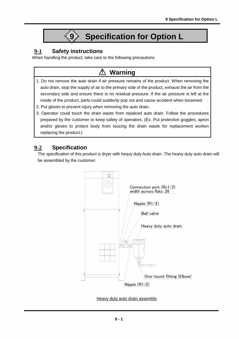
9-2 Specification The specification of this product is dryer with heavy duty Auto drain .The heavy duty auto drain will be assembled by the customer.
Heavy duty auto drain assembly
Nipple (R1/2)
One-touch fitting (Elbow)
Heavy duty auto drain
Ball valve
Connection port (Rc1/2)
Nipple (R1/2)
width across flats:26
9 - 1

9 Specification for Option L
9-3 Specification of heavy duty auto drain (ADH4000-04). Model IDU8E ~ 15E-10/20/23-L Auto drain type Floating type Auto drain valve type N.O(normally opened: Open in the case of pressure loss)Max. operating pressure 1.6MPa Working pressure range 0.05 to 1.6MPa Working fluid Compressed air Max. drain discharge 400cc/min(Pressure 0.7MPa,the case of water)
Note) Use for air compressor with flow more than 50l/min (ANR).
9-4 Installation of heavy duty auto drain 1. Hold the hexagon-head part (width across flats: 26) at port Rc1/2 of the air dryer with spanner.
Then install nipple, ball valve (width across flats: 25). Note 1) Put up the seal tape or the sealant to the nipple. Torque R1/2 : 28 to 30N・m
2. Hold the ball valve with the spanner. Then install a nipple and a heavy duty auto drain. Install with “out port" down in a vertical position. Inclination from the vertical line should be less than 5°.
3. Install one-touch fitting (width across flats: 22) to drain port (width across flats: 27) and the drain tube.
Nipple
Heavy duty auto drain
Ball valve
(Pilot exhaust port)
(Flushing button) (Bleed valve)
9-5 Maintenance 1. Check drain condition periodically (more than once a day).
Then push flushing button to open exhaust valve.
2. Pilot air is exhaust from the port indicated in the figure. Do not cover this exhaust port. Clean exhaust port so that port is not blocked by dust, etc.
3. Close the ball valve before removing the heavy duty auto drain and open the bleed valve or push
the flushing button and confirm air pressure is 0.
9 - 2

10 Specification for Option M
10 Specification for Option M
The motor-type auto drain described in item 2 “Specifications of the motor-type auto drain” is used for this refrigerated air dryer. Please pay attention to the warning below for the installation and maintenance of this dryer.
10-1 Safety instructions When handling the product, take care to the following precautions.
Warning 1. Do not remove the auto drain if air pressure remains of the product. When removing the
auto drain, stop the supply of air to the primary side of the product, exhaust the air from the secondary side and ensure there is no residual pressure. If the air pressure is left at the inside of the product, parts could suddenly pop out and cause accident when loosened.
2. Put gloves to prevent injury when removing the auto drain.
3. Operator could touch the drain waste from repalced auto drain. Follow the procedures prepared by the customer to keep safety of operators. (Ex. Put protective goggles, apron and/or gloves to protect body from toucing the drain waste for replacement worken replacing the product.)
Warning Only qualified person must perform wiring. 1. Provide the power suitable for the product specifications. 2. Be suer to ground the product for the safety. Do not ground to water pipe, gas tube or
lightening rod line. 3. Do not connect too many wires to the same outlet, which could results in heat generation
and fire. 4. Do not retrofit the wiring of the dryer and the power supply line.
10 - 1

10 Specification for Option M
10-2 Specifications The motor-type auto drain is available in this option specification. The installation of this motor-type auto drain is different from the standard but mounted onto the outside of the unit.
(R1/2)
(Rc3/8)
Nipple
Ball valve
Drip proof connector
Connection port size(Rc1/2)Width across flats:26
Motor-type auto drain
Drain exhaust port
The parts in the dotted rectangle are packaged together
with the unit as accessories.
Model
Items IDU8E to 15E-10-M IDU8E to 15E-20-M
Order number IDF-S0087 IDF-S0090
Max. operating pressure 1.0MPa
Operating fluid Compressed air
Operating cycle Once every minute
Operating time 2 seconds/cycle
Power supply voltage of dryer AC100V(50/60Hz) AC200V(50/60Hz)
Power consumption 4W
10 - 2

10 Specification for Option M
10-3 Installation of the motor-type auto drain
1. Hold the hexagonal part of the connection port Rc1/2 (width across flats: 26) of the air dryer
with a spanner wrench and screw in the nipple and ball valve (width across flats) with seal tape
or sealant.
2. Hold the ball valve with a spanner wrench and screw in the nipple and the motor-type auto
drain (width across flats of the drain inlet port: 30) firmly. Mount the motor-type auto drain
vertically with the drain outlet pointed downward (inclination tolerance in the vertical direction is
5 o).
3. Connect the 2 electric cables coming out from the auto drain with the two electric cables from
the dryer unit. Insert the drip-proof connector to the deepest part.
[Reference] Tightening torque R1/2: 28 to 30Nm
Nipple
Ball Valve Motor Type Auto Drain
10 - 3

11 Specification for Option R
11 Specification for Option R
This product mounts the Ground Fault Circuit Interrupter (GFCI) in Item 2. It will shut off the power
supply in case the product should have over current or current leakage. Additionally, the power
supply should be connected directly to the primary side of the GFCI. For the details of the GFCI such
as the specifications and mounting position, refer to Item 2 or later.
11-1 Safety instructions When handling the product, take care to the following precautions.
Warning
Only qualified person must perform wiring and obserbing the following points. 1. Be sure to shut off the power supply before wiring. For safety, do not perform any work on the unit
with the power supply on. The power supply cannot be completely shut off just by turning off the illuminated switch. Be sure to turn off all power lines connected to the product.
2. Supply the power from a stable source, free from surges. 3. Provide the power suitable for the product specifications. 4. Be sure to ground the product for the safety. Without grounding, the GFCI can not operate normally. 5. Do not ground to water pipe, gas tube or lightening rod line. 6. Do not connect too many wires to the same outlet, which could results in heat generation and fire. 7. Do not retrofit the wiring of the dryer and the power supply line.
11 - 1

11 Specification for Option R
11-2 Specifications of the GFCI
Dryer model number Specifications of GFCI
IDU8E/11E-20/23-R Rated current: 5A, Current sensitivity: 30mA
IDU8E/11E-10-R IDU15E-10/20/23-R Rated current: 10A, Current sensitivity: 30mA
11-3 How to connect the power supply
Connect the power cables in the following procedure. 1) Take off the rear panel. 2) Insert the power cable prepared by the customer into the power code fixture and bring the
power cable near the terminal base through the base hole. 3) Connect the power cable to the terminal of the GFCI. 4) Connect the ground line. ・ AC100V: Connect the ground line to M4 screw on the left side of the GFCI (with the name plate). ・ AC200V: Connect it to the terminal block (ground connection thread: M3) 5) Mount the rear panel.
Electrical entry
GFCI
Rear panel
L N
Connect to power cable Connector width:9.6mm or less
Connect to earth cable Connector width:6.5mm or less
11 - 2

12 Specification for Option S
12 Specification for Option S
The power supply terminal block in item 2 is incorporated into this refrigerated air dryer. Please see item 2 and subsequent items for details.
12-1 Safety instructions When handling the product, take care to the following precautions.
Warning
9. For the use of the product in Europe, mount the breaker compatible to IEC standard to the power supply for the product.
8. Do not retrofit the wiring of the dryer and the power supply line.
6. Do not ground to water pipe, gas tube or lightening rod line. 7. Do not connect too many wires to the same outlet, which could results in heat generation and fire.
2. Supply the power from a stable source, free from surges. 3. Be sure to mount the Ground Fault Circuit Interrupter (GFCI) with adequate sensitivity and load
capacity to prevent electrical shock and protect the refrigerating compressor motor from burning out.
4. Provide the power suitable for the product specifications. 5. Be sure to ground the product for the safety. Without grounding, the GFCI can not operate
normally.
1. Be sure to shut off the power supply before wiring. For safety, do not perform any work on the unit with the power supply on. The power supply cannot be completely shut off just by turning off the switch with lamp. Be sure to turn off all power lines connected to the product.
Only qualified person must perform wiring and obserbing the following points.
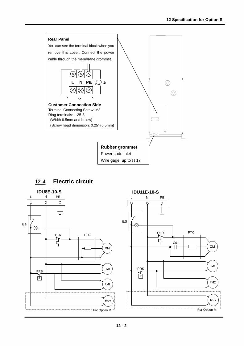
12-2 Specifications The power supply and terminal block can be connected in this option specification. On the customer side, the terminal block should be used for the power supply instead of the standard plug receptacle (Power supply AC100V type). The terminal block is mounted onto the lower part of the rear side (IN and OUT ports sides).
12-3 How to connect the power supply cable Connect the power supply cable in the following procedures.
1) Take off the rear panel. 2) Insert the power supply cable prepared by the customer into the power code inlet (with rubber
grommet) and bring the power supply cable near the terminal block through the base hole. 3) Connect the power supply cable to the terminal. 4) Connect the ground line. 5) Mount the rear panel (5 pcs of M4 screw).
12 - 1
12 Specification for Option S
Rear Panel You can see the terminal block when you
remove this cover. Connect the power
cable through the membrane grommet.
Rubber grommet Power code inlet Wire gage: up to φ17
L N PE
( )
Customer Connection Side Terminal Connecting Screw: M3 Ring terminals: 1.25-3
(Width 6.5mm and below) (Screw head dimension: 0.25” (6.5mm)
12-4 Electric circuit
IDU8E-10-S IDU11E-10-S
CM
ILS
OLR
P
PRS
PTC
FM1
PEL N
FM2
MOV
For Option M
CM
ILS
OLR
P
PRS
PTC
FM1
PEL N
FM2
MOV
For Option M
C01
12 - 2

12 Specification for Option S
IDU15E-10-S
ILS
OLR
P
PRSFM1
FM2
C11
C12
C02R
CM
C01
RY
RY
TM
PEL NTB
SYMBOL DESCRIPTION
CM Compressor MotorFM1 Fan Motor For CondensorFM2 Fan Motor For After CoolerOLR Overload RelayPTC PTC StarterILS Switch With LampPRS Pressure SwitchC01 Capacitor For Starting Compressor MotorC02 Capacitor For Running Compressor MotorTB Terminal BlockR Resister
RY Starting RelayMOV Motor Type Auto Drain
12 - 3

13 Specification for Option T
13 Specification for Option T
This product mounts the terminal block which can transfer the operation and failure signals to Item 2 Specifications. The signals are a no voltage contact style. For details, refer to Item 2 or later.
13-1 Safety instructions When handling the product, take care to the following precautions.
Only qualified person must perform wiring and obserbing the following points. 1. Be sure to shut off the power supply before wiring. For safety, do not perform any work on the unit
with the power supply on. The power supply cannot be completely shut off just by turning off the switch with lamp. Be sure to turn off all power lines connected to the product.
2. Supply the power from a stable source, free from surges. 3. Be sure to mount the Ground Fault Circuit Interrupter (GFCI) with adequate sensitivity and load
capacity to prevent electrical shock and protect the refrigerating compressor motor from burning out.
4. Provide the power suitable for the product specifications. 5. Be sure to ground the product for the safety. Without grounding, the GFCI can not operate
normally. 6. Do not ground to water pipe, gas tube or lightening rod line. 7. Do not connect too many wires to the same outlet, which could results in heat generation and fire. 8. Do not retrofit the wiring of the dryer and the power supply line. 9. For the use of the product in Europe, mount the breaker compatible to IEC standard to the power
supply for the product.
Warning
13-2 Specifications The product mounts the terminal block which can transfer the operation and failure signals on the standard product. ・The operation and failure signals are no voltage contact style.
Operation・・・・・When the product is operating; Close Failure・・・When the product stops due to failure; Close
・Contact capacity IDU8E ~ 15E-10/20
AC220V, 6A DC24V, 6A Minimum current for signal 24V, 300mA(AC/DC)
IDU8E ~ 15E-23 AC230V, 4A DC24V, 5A Minimum current for signal 20V, 5mA(AC/DC)
13 - 1

13 Specification for Option T
13-3 Remote operation ・For the remote operation, turn on and off the power supply side under the condition of the switch
with lamp ON.
・Keep 3 min. at minimum after stopping the product to restart even for the remote operation. If the
product is restarted within less than 3 min., protective equipment (overload relay) may activate and
prevent the product from restarting.
Additionally, the frequency to start and stop the operation must be restricted to 5 times per hour (to
prevent breakage of the motor).
13-4 How to connect the power supply and signal cable Connect the power cable and signal cable in the following procedures.
1) Take off the rear panel. 2) Insert the power cable prepared by the customer into the power code inlet (with rubber
grommet) and bring the power cable near the terminal block through the base hole. 3) Connect the power cable to the terminal. 4) Insert the signal cable prepared by the customer into the signal code inlet (with rubber
grommet) and bring the signal cable near the terminal block. 5) Connect the signal cable to the each terminal. 6) Mount the rear panel.
Terminal block
1 2 3PENL
Rear panel
Customer connection side Terminal connecting screw: M3 Crimping terminal width: 6.5mm and below
Applicable electrical wire:1.25mm2 or more Rubber grommet Rubber grommet Power code inlet Signal code inlet Wire gage: up to φ17 Wire gage: up to φ17
13 - 2

13 Specification for Option T
13-5 Electric circuit IDU8E-10-T IDU8E/11E-20-T
TB
L N PE
CM
P
ILS
PTCOLR
PE
PRS
PE
1 2 3
MC TDR
TDR
TDR
MC
MC
FM2PE
GFGIFor Option R
MC
Operation Failurte
FM1C11
C12
TB
L N PE
CM
FM1
P
ILS
PTCOLR
PE
PRSPE
1 2 3
MC TDR
TDR
TDR
MC
MC
FM2PE
GFGIFor Option R
MC
Operation Failurte
IDU8E/11E-23-T IDU11E-10-T
TBL N PE
CM
P
ILS
PTCOLR
PE
PRS
1 2 3
MC TDR
TDR
TDR
MC
MC
GFGIFor Option R
MC
FM2PE
Operation Failure
PEFM1
C01
TB
L N PE
FM1
FM2
P
ILS
OLR
PE
PRS
GFGIFor Option R
EDV
For Option V
PTC
CM
1 2 3Operation Failure
MC TDR
TDR
MC
MC
TDR
C11
C12MC
13 - 3

13 Specification for Option T
IDU15E-10-T IDU15E-20-T
IDU15E-23-T
CM Compressor Motor
FM1 Fan Motor For Condensor
FM2 Fan Motor For After Cooler
FM3 Fan Motor For CompressorOLR Overload RelayILS Switch with Lamp
PRS Pressure SwitchPTC PTC StarterC01 Capacitor For Startiong Compressor MotorC02 Capacitor For Running Compressor Motor
C11,C12 Capacitor For Running Fan MotorTB Terminal BlockRY Starting RelayR Resister
TM Terminal BlockTDR Time Delay RealyMC Magnetic Contactor
MOV Motor Type Auto DrainGFCI Ground Fault Circuit InterrupterEDV Electronic Drain Valve
T
L N PE
P
CM
ILS
OLR
PE
PE
PRS
PTC
MC TDR
MC
TDR
TDR
1 2 3Operation Failure
T
L N PE
P
ILS
OLR
PEC11
PRS
PTC
MC TDR
MC
TDR
TDR
1 2 3
MC
FM2PEC12
CR
FM1
Operation Failure
MC
CMPE
MC
RY
C02
RY
C02
MC
FM2PEC12
FM1
TM
MC
RY
RY
C01R
TB
L N PE
FM1
P
ILS
OLR
PE
PRS
GFGIFor Option R
EDV
For Option V
PTC
CM
1 2 3Operation Failure
MC TDR
TDRMC
TDR
MC
FM3
C11
MC
FM2C12
RY
RY
C0
13 - 4

14 Specification for Option V
14 Specification for Option V
This product mounts the electronic drain valve in Item 2 Specifications. When performing the installation and maintenance work for the product, the following points must be understood and followed. Additionally, read Item 3 for replacement work.
14-1 Safety instructions When handling the product, take care to the following precautions.
Warning 1. Do not remove the auto drain if air pressure remains of the product. When removing the
auto drain, stop the supply of air to the primary side of the product, exhaust the air from the secondary side and ensure there is no residual pressure. If the air pressure is left at the inside of the product, parts could suddenly pop out and cause accident when loosened.
2. Put gloves to prevent injury when removing the auto drain.
3. Operator could touch the drain waste from repalced auto drain. Follow the procedures prepared by the customer to keep safety of operators. (Ex. Put protective goggles, apron and/or gloves to protect body from toucing the drain waste for replacement worken replacing the product.)
Warning Only qualified person must perform wiring. 1. Provide the power suitable for the product specifications. 2. Be suer to ground the product for the safety. Do not ground to water pipe, gas tube or
lightening rod line. 3. Do not connect too many wires to the same outlet, which could results in heat generation
and fire. 4. Do not retrofit the wiring of the dryer and the power supply line.
14 - 1

14 Specification for Option V
14-2 Specifications The timer is set to have ON time of 0.5sec and OFF time of 0.5min. at the time of shipment from the
factory. Do not change this timer setting. If it is changed, water could be discharged from the outlet
line of the dryer. Service parts number will change depending on the power supply voltage of the
dryer.
Power supply voltage of dryer AC230V
Order number (service parts) IDF-S0198 Max. operating pressure 1.6MPa Fluid Drain Power supply voltage of drain timer AC230V±10% (50Hz) ON time 0.5sec OFF time 0.5min
14-3 How to perform maintenance The product needs to be maintained. Clean it in the following procedure periodically.
1) Close the ball valve. 2) Press the test switch and make the residual pressure zero. 3) Remove the strainer and clean it. 4) Reassemble the strainer and open the ball valve.
ON OFF
ON:SEC OFF:MIN0.5
2
4 6
8
10 0.5
1
2 3
4
5
Built-in strainer
Ball valve
Test switch
Strainer lid
14 - 2

15 Service Record
15 Service Record
15-1 Service Record I t is recommended to keep a maintenance/service record.
Parts No. Description Maintenance/Service Work Description Date
15 - 1