Embed Size (px)
Citation preview
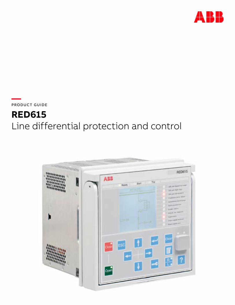
— PRODUC T GUIDE
RED615Line differential protection and control
2 R E D 61 5 L I N E D I FFER ENTI A L PR OTEC TI O N A N D CO NTR O L
— Table of contents
004 Description
004 Standard configurations
010 Protection funtions
010 Application
013 Supported ABB solutions
014 Control
015 Measurements
015 Power quality
015 Fault location
015 Disturbance recorder
016 Event log
016 Recorded data
016 Condition monitoring
017 Trip-circuit supervision
017 Self-supervision
017 Current circuit supervision 017 Protection, communnication and supervision
3
— Table of contents
018 Access control Inputs and outputs
018 Inputs and outputs
019-023 Station communication
024– 053 Technical data
054 Local HMI
055 Mounting methods
055 Relay case and plug-in unit
055 Selection and ordering data
056 Accesories and ordering data
056 Tools
057 Cyber security
058-059 Terminal diagrams
060 Certificates
060 References
061– 062 Functions, codes, and symbols
062 Document revision history
4 R E D 61 5 L I N E D I FFER ENTI A L PR OTEC TI O N A N D CO NTR O L
1. Description RED615 is a phase-segregated two-end line differential protection and control relay designed for utility and industrial power systems, including radial, looped and meshed distribution networks with or without distributed power generation. RED615 is also designed for the protection of line differential applications with a transformer within the protection zone. RED615 relays communicate between substations over a fiber optic link or a galvanic pilot wire connection. RED615 is a member of ABB’s Relion® product family and part of its 615 protection and control product series. The 615 series relays are characterized by their compactness and withdrawable-unit design. Re-engineered from the ground up, the 615 series has been guided by the IEC 61850 standard for communication and interoperability of substation automation equipment.
The relay provides unit type main protection for overhead lines and cable feeders in distribution networks. The relay also features current-based protection functions for remote backup for down-stream protection relays and local back-up for the line differential main protection. Standard configurations D and E include directional overcurrent and voltage based protection functions.
The relay is adapted for the protection of overhead line and cable feeders in isolated neutral, resistance grounded, compensated (impedance grounded)
and solidly grounded networks. Once the relay has been given the application specific settings, it can directly be put into service.
The 615 series relays support a range of communication protocols including IEC 61850 with Edition 2 support, process bus according to IEC 61850-9-2 LE, Modbus® and DNP3.
2. Standard configurationsRED615 is available in two alternative standard configurations. The standard signal configuration can be altered by means of the signal matrix or the graphical application functionality of the Protection and Control Relay Manager PCM600. Further, the application configuration functionality of PCM600 supports the creation of multi-layer logic functions utilizing various logical elements including timers and flip-flops. By combining protection functions with logic function blocks the relay configuration can be adapted to user specific application requirements.
The relay is delivered from the factory with default connections described in the functional diagrams for binary inputs, binary outputs, function-to-function connections and alarm LEDs. Some of the supported functions in RED615 must be added with the Application Configuration tool to be available in the Signal Matrix tool and in the relay. The positive measuring direction of directional protection functions is towards the outgoing feeder.
—RED615Line differential protection and control
5
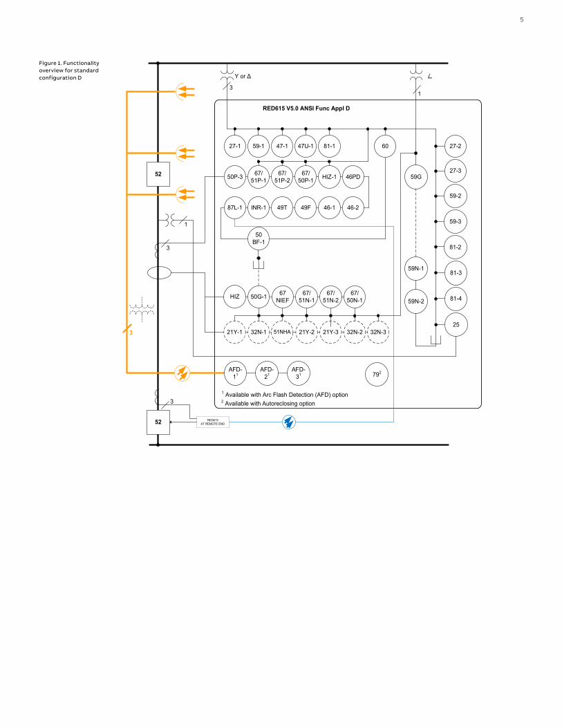
Figure 1. Functionality overview for standard configuration D
RED615AT REMOTE END
3
52
3
RED615 V5.0 ANSI Func Appl D
50P-3 67/51P-1
3
27-1 59-1
1 Available with Arc Flash Detection (AFD) option
AFD-31
47-1 47U-1
AFD-11
AFD-21
81-1
67/51P-2 59G67/
50P-1
49T 49F
46PD
INR-187L-1
59N-1
60
Υ or Δ Δ
21Y-1 32N-1
46-246-1
50BF-1
27-2
27-3
59-2
59-3
81-2
81-3
81-4
21Y-2 21Y-3 32N-2 32N-325
HIZ-1
52
1
1
59N-2HIZ 50G-1 67
NIEF67/
51N-167/
51N-267/
50N-1
51NHA
792
2 Available with Autoreclosing option3

RED615AT REMOTE END
3I
52
3
RED615 V5.0 ANSI Func Appl E
50P-3 67/51P-1
27-1 59-1
1 Available with Arc Flash Detection (AFD) option
AFD-31
47-1 47U-1
AFD-11 AFD-21
81-1
67/51P-2 59G67/
50P-1
49T 49F
46PD
INR-187L-1 59N-1
60
Va, Vb, Vc
21Y-13 32N-14
46-246-1
50BF-1
25
27-2
27-3
59-2
59-3
81-2
81-3
21Y-23 32N-3481-4
HIZ-1
52
59N-2
67NEIF
67/51N-1
67/51N-2
67/50N-1
51NHA5
792
2 Available with Autoreclosing option3I
IEC 61850-9-2LE
100100100100101010
1000011
3 Available with Admittance-based earth fault protection4 Available with Wattmetric-based earth fault protection5 Available with Harmonic-based earth fault protection
50G-1
32N-2421Y-33
6 R E D 61 5 L I N E D I FFER ENTI A L PR OTEC TI O N A N D CO NTR O L
Figure 2. Functionality overview for standard configuration E
—Table 1. Standard configurations
Description Std. conf.
Line differential protection with directional O/C, directional E/F, voltage & frequency based protection & measurements, synchro-check and CB condition monitoring (RTD option, optional power quality and fault locator) D
Line differential protection with directional O/C, directional E/F, voltage and frequency based protection & measurements and CB condition monitoring (Sensor inputs, optional power quality, fault locator and synchro-check with IEC61850-9-2LE) E

7
—Table 2. Supported functions
Function IEC 61850 ANSI C D
Protection
Three-phase non-directional overcurrent protection, instantaneous stage PHIPTOC 50P-3 1 1
Three-phase directional overcurrent protection, low stage DPHLPDOC 67/51P 2 2
Three-phase directional overcurrent protection, high stage DPHHPDOC 67/50P 1 1
Non-directional ground-fault protection, high stage EFHPTOC 50G 1 4) 1 4)
Directional ground-fault protection, low stage DEFLPDEF 67/51N 2 5) 9) 2 5) 10)
Directional ground-fault protection, high stage DEFHPDEF 67/50N 1 5) 10)
Admittance-based ground-fault protection 1) EFPADM 21YN (3) 1) 4) 9) (3) 1) 4) 11)
Wattmetric-based ground-fault protection 1) WPWDE 32N (3) 1) 4) 9) (3) 1) 4) 11)
Transient/intermittent ground-fault protection INTRPTEF 67NIEF 1 9) 15) 1 11) 15)
Harmonics-based ground-fault protection 1) HAEFPTOC 51NHA (1) 1) 15) 19) (1) 1) 15) 19)
Negative-sequence overcurrent protection NSPTOC 46 2 2
Phase discontinuity protection PDNSPTOC 46PD 1 1
19) 19)
112) 112)
Residual overvoltage protection ROVPTOV 59G/59N 112) 19) 112) 19)
Three-phase undervoltage protection PHPTUV 272
119)
2 119)
Three-phase overvoltage protection PHPTOV 592
119)
2 119)
Positive-sequence undervoltage protection PSPTUV 47U 1 1
Negative-sequence overvoltage protection NSPTOV 47 1 1
Frequency protection FRPFRQ 81 419) 419)
Three-phase thermal protection for feeders, cables and distribution transformers T1PTTR 49F 1 1
Three-phase thermal protection for feeders, cables and distribution transformers T2PTTR 49T 1 1
Binary signal transfer BSTGGIO BST 1 1
Circuit breaker failure protection CCBRBRF 50BF 1 1
Three-phase inrush detector INRPHAR INR 1 1
Switch onto fault CBPSOF SOTF 119)" 119)"
Master trip TRPPTRC 86/94 2 2
Multipurpose protection 2) MAPGAPC MAP 1819) 1819)
Fault locator SCEFRFLO 21FL (1)19) (1)19)
Line differential protection with in-zone power transformer LNPLDF 87L 1 1
High-impedance fault detection PHIZ HIZ 119)
Power quality
Current total demand distortion CMHAI PQI (1)17) 19) (1)17) 19)
Voltage total harmonic distortion VMHAI PQVPH (1)17) 19) (1)17) 19)
Voltage variation PHQVVR PQSS (1)17) 19) (1)17) 19)
Voltage unbalance VSQVUB PQVUB (1)17) 19) (1)17) 19)
Control
Circuit breaker control CBXCBR 52 1 1
Disconnector control DCXSWI 29DS 219) 219)
Grounding switch control ESXSWI 29GS 119) 119)
Disconnector position indication DCSXSWI 52-TOC, 29DS1 19)
219
1 19)
219
Grounding switch indication ESSXSWI 29GS 219) 219)
Autoreclosing DARREC 79 (1) (1)
Synchronism and energizing check SECRSYN 25 119) (1)26)19)
Condition monitoring and supervision
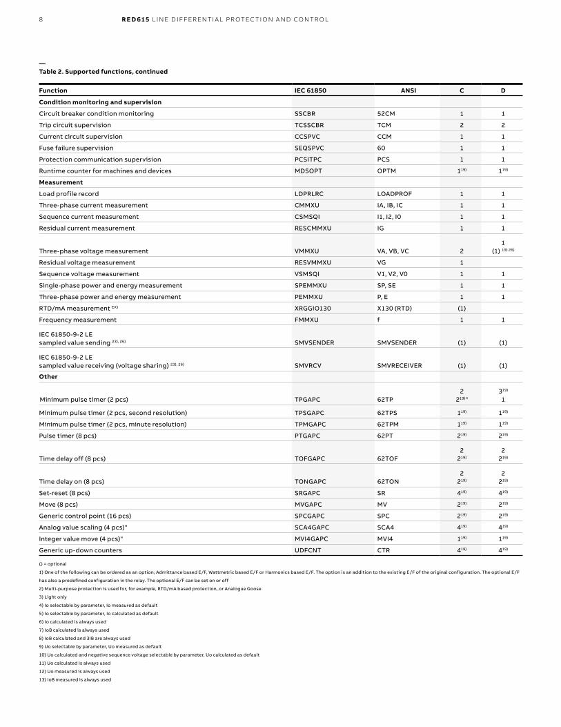
8 R E D 61 5 L I N E D I FFER ENTI A L PR OTEC TI O N A N D CO NTR O L
Function IEC 61850 ANSI C D
Condition monitoring and supervision
Circuit breaker condition monitoring SSCBR 52CM 1 1
Trip circuit supervision TCSSCBR TCM 2 2
Current circuit supervision CCSPVC CCM 1 1
Fuse failure supervision SEQSPVC 60 1 1
Protection communication supervision PCSITPC PCS 1 1
Runtime counter for machines and devices MDSOPT OPTM 119) 119)
Measurement
Load profile record LDPRLRC LOADPROF 1 1
Three-phase current measurement CMMXU IA, IB, IC 1 1
Sequence current measurement CSMSQI I1, I2, I0 1 1
Residual current measurement RESCMMXU IG 1 1
Three-phase voltage measurement VMMXU VA, VB, VC 21
(1) 19) 26)
Residual voltage measurement RESVMMXU VG 1
Sequence voltage measurement VSMSQI V1, V2, V0 1 1
Single-phase power and energy measurement SPEMMXU SP, SE 1 1
Three-phase power and energy measurement PEMMXU P, E 1 1
RTD/mA measurement EX) XRGGIO130 X130 (RTD) (1)
Frequency measurement FMMXU f 1 1
IEC 61850-9-2 LE sampled value sending 23), 26) SMVSENDER SMVSENDER (1) (1)
IEC 61850-9-2 LE sampled value receiving (voltage sharing) 23), 26) SMVRCV SMVRECEIVER (1) (1)
Other
se timer Minimum pulse timer (2 pcs) (2 pcs)" TPGAPC 62TP2
219)"319) 1
Minimum pulse timer (2 pcs, second resolution) TPSGAPC 62TPS 119) 119)
Minimum pulse timer (2 pcs, minute resolution) TPMGAPC 62TPM 119) 119)
Pulse timer (8 pcs) PTGAPC 62PT 219) 219)
Time delay off (8 pcs) TOFGAPC 62TOF2
219)
2 219)
Time delay on (8 pcs) TONGAPC 62TON2
219)
2 219)
Set-reset (8 pcs) SRGAPC SR 419) 419)
Move (8 pcs) MVGAPC MV 219) 219)
Generic control point (16 pcs) SPCGAPC SPC 219) 219)
Analog value scaling (4 pcs)" SCA4GAPC SCA4 419) 419)
Integer value move (4 pcs)" MVI4GAPC MVI4 119) 119)
Generic up-down counters UDFCNT CTR 419) 419)
—Table 2. Supported functions, continued
() = optional
1) One of the following can be ordered as an option; Admittance based E/F, Wattmetric based E/F or Harmonics based E/F. The option is an addition to the existing E/F of the original configuration. The optional E/F
has also a predefined configuration in the relay. The optional E/F can be set on or off
2) Multi-purpose protection is used for, for example, RTD/mA based protection, or Analogue Goose
3) Light only
4) Io selectable by parameter, Io measured as default
5) Io selectable by parameter, Io calculated as default
6) Io calculated is always used
7) IoB calculated is always used
8) IoB calculated and 3IB are always used
9) Uo selectable by parameter, Uo measured as default
10) Uo calculated and negative sequence voltage selectable by parameter, Uo calculated as default
11) Uo calculated is always used
12) Uo measured is always used
13) IoB measured is always used

9
14) IoB measured and 3IB are always used
15) Io measured is always used
16) IoB selectable by parameter, IoB measured as default
17) Power quality option includes Current total demand distortion, Voltage total harmonic distortion and Voltage variation
18) Available in IED and SMT but not connected to anything in logic
19) Must be added with ACT to be available in SMT and in protection relay
20) Uob measured is always used for unbalance protection with ungrounded single Y connected capacitor bank.
21) The Iunb measurements values will be taken from this block and put in Measurent view.
22) Master Trip included and connected to corresponding HSO in the configuration only when BIO0007 module is used. If
additionally the ARC option is selected, then ARCSARC is connected in the configuration to the corresponding Master Trip input.
23) Only available with COM0031-0037
24) Power quality option includes only Current total demand distortion
25) Unbalance voltage measurement for capacitor bank for REV615
26) Only available with IEC 61850-9-2
LV) The function block is to be used on the low voltage side in the application
HV) The function block is to be used on the high voltage side in the application
NT) The function block is to be used on the neutral side in the application
TR) The function block is to be used on the terminal side in the application
BS) The function block is to be used on the bus side in the application
EX) This function to be excluded from the Integration Test Data generation

10 R E D 61 5 L I N E D I FFER ENTI A L PR OTEC TI O N A N D CO NTR O L
3. Protection functionsThe relay offers two-stage phase-segregated line differential protection, phase overcurrent protection, negative-sequence overcurrent protection and circuit breaker failure protection. Depending on the chosen standard configuration, the basic functionality can be extended by thermal overload protection, non-directional or directional overcurrent protection, directional or non-directional ground-fault protection, sensitive ground-fault protection, phase discontinuity protection, transient/intermittent ground-fault protection, residual overvoltage protection, phase-voltage and frequency based protection and three-pole multi-shot auto-reclosing functions for overhead line feeders. For standard configurations B, D and E, admittance-based, watt-metric-based or harmonics-based ground-fault protection is offered as an option in addition to the directional ground-fault protection.
The line differential protection function includes a stabilized low stage and an instantaneous high stage. The stabilized low stage provides sensitive differential protection and remains stable during, for example, current transformer saturation conditions. The low-stage operation can be restrained using second harmonic detection if an out-of-zone power transformer is to be energized. The instantaneous high stage offers less sensitive differential protection but enables fast operation during high fault currents. If there is an in-zone transformer in the protection zone, the vector group is automatically compensated based on the winding types and clock number setting values.The operating time characteristic for the low stage can be set to definite time or inverse definite time mode. The direct intertrip function ensures that both ends are always simultaneously tripped, independent of the fault current contribution.
4. Application RED615 can be used in a variety of applications requiring an absolutely selective unit type protection system. The zone-of protection of a line differential protection system is the feeder section defined by the location of the current transformers in the local and the remote substation. RED615 can also be used for line differential protection if there is an in-zone transformer in the protected feeder section. Combining horizontal GOOSE communication over a station bus and binary signal transfer over the protection communication link offers new
application possibilities beyond traditional line differential protection. One interesting application based on inter-substation signal transfer is loss of mains (LOM) protection in networks with distributed generation. The performance of the combination of binary signal transfer and horizontal GOOSE communication performance as to speed, selectivity and reliability are hard to match with conventional loss-of-mains protection.
RED615 is the ideal relay for the protection of feeders in network configurations containing closed loops. Under normal operating conditions the feeder loop is closed. The aim of the closed loop is to secure the availability of power for the end users. As a result of the closed loop configuration, any fault spot in the system will be fed with fault current from two directions. Using plain overcurrent protection, either directional or non-directional, it is difficult to obtain fast and selective short circuit protection. With RED615 line differential protection relays the faulty part of the network can be selectively isolated, thus securing power distribution to the healthy part of the network.
The standard configuration E includes one conventional residual current (Io) input and three combi-sensor inputs for phase currents and phase voltages. The connection of the three combi-sensors is made with RJ-45 type of connectors. Sensors offer certain benefits compared to conventional current and voltage instrument transformers. For example, current sensors do not saturate at high currents, they consume less energy and they weigh less. In voltage sensors the risk of ferro-resonance is eliminated. The sensor inputs also enable the use of the relay in compact medium voltage switchgears, such as ABB’s ReliaGear ND Digital, Advance Digital, and SafeGear Digital, with limited space for conventional measuring transformers, thus requiring the use of sensor technology. Further, the adapters also enable the use of sensors with Twin-BNC connectors.
Under certain operational circumstances, such as maintenance of primary equipment or substation extension projects there will be a need to interconnect network parts, which normally are separated. To avoid major re-parameterization of the protection devices of the network when the network topology is changed, line differential protection relays can be used to obtain absolutely selective feeder protection in looped networks.
3
523
Υ or Δ Δ V0a
3
RED615 Conf D
274650BF51P/50P5967/51P/50P87L
52
RED615 Conf D
274650BF51P/50P5967/51P/50P87L
3
Υ or Δ Δ V0a
Protectioncommunication
11
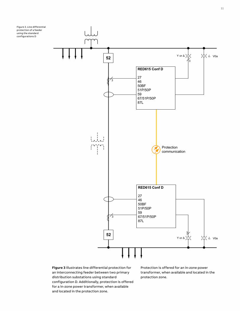
Figure 3. Line differential protection of a feeder using the standard configurations D
Figure 3 illustrates line differential protection for an interconnecting feeder between two primary distribution substations using standard configuration D. Additionally, protection is offered for a in-zone power transformer, when available and located in the protection zone.
Protection is offered for an in-zone power transformer, when available and located in the protection zone.
3I
52
RED615 Conf E
274650BF51P/50P5967/51P/50P87L
52
3I
Va, Vb, Vc
RED615 Conf E
274650BF51P/50P5967/51P/50P87L
Va, Vb, Vc
Protectioncommunication
12 R E D 61 5 L I N E D I FFER ENTI A L PR OTEC TI O N A N D CO NTR O L
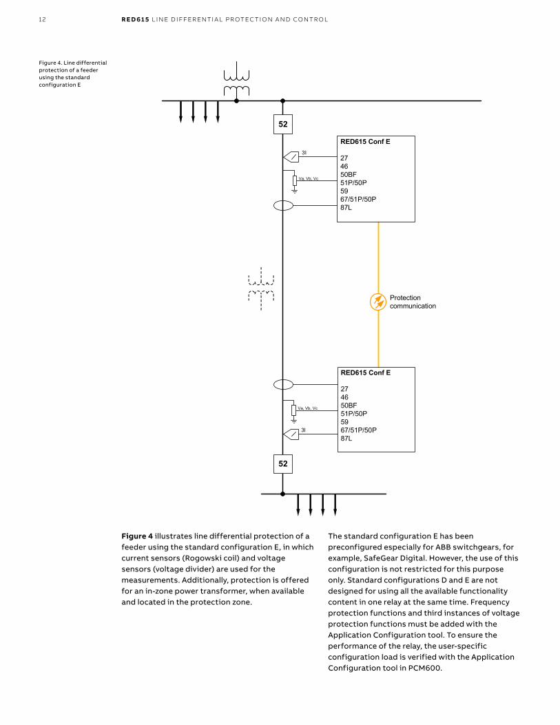
Figure 4. Line differential protection of a feeder using the standard configuration E
Figure 4 illustrates line differential protection of a feeder using the standard configuration E, in which current sensors (Rogowski coil) and voltage sensors (voltage divider) are used for the measurements. Additionally, protection is offered for an in-zone power transformer, when available and located in the protection zone.
The standard configuration E has been preconfigured especially for ABB switchgears, for example, SafeGear Digital. However, the use of this configuration is not restricted for this purpose only. Standard configurations D and E are not designed for using all the available functionality content in one relay at the same time. Frequency protection functions and third instances of voltage protection functions must be added with the Application Configuration tool. To ensure the performance of the relay, the user-specific configuration load is verified with the Application Configuration tool in PCM600.
13
5. Supported ABB solutions The 615 series protection relays together with the Substation Management Unit COM600F constitute a genuine IEC 61850 solution for reliable power distribution in utility and industrial power systems. To facilitate the system engineering, ABB's relays are supplied with connectivity packages. The connectivity packages include a compilation of software and relay-specific information, including single-line diagram templates and a full relay data model. The data model includes event and parameter lists. With the connectivity packages, the relays can be readily configured using PCM600 and integrated with COM600F or the network control and management system MicroSCADA Pro.
The 615 series relays offer native support for IEC 61850 Edition 2 also including binary and analog horizontal GOOSE messaging. In addition, process bus with the sending of sampled values of analog currents and voltages and the receiving of sampled values of voltages is supported. Compared to traditional hard-wired, inter-device signaling, peer-to-peer communication over a switched Ethernet LAN offers an advanced and versatile platform for power system protection. Among the distinctive features of the protection system approach, enabled by the full implementation of the IEC 61850 substation automation standard, are fast communication capability, continuous supervision of the protection and communication system's integrity, and an inherent flexibility regarding reconfiguration and upgrades.This protection relay series is able to optimally utilize interoperability provided by the IEC 61850 Edition 2 features. At substation level, COM600F uses the data content of the bay level devices to enhance substation level functionality.
COM600F features a Web browser-based HMI, which provides a customizable graphical display for visualizing single-line mimic diagrams for switchgear bay solutions. The Web HMI of COM600F also provides an overview of the whole substation, including relay-specific single-line diagrams, which makes information easily accessible. Substation devices and processes can also be remotely accessed through the Web HMI, which improves personnel safety.
In addition, COM600F can be used as a local data warehouse for the substation's technical documentation and for the network data collected by the devices. The collected network data facilitates extensive reporting and analyzing of network fault situations by using the data historian and event handling features of COM600F. The historical data can be used for accurate monitoring of process and equipment performance, using calculations based on both real-time and historical values. A better understanding of the process dynamics is achieved by combining time-based process measurements with production and maintenance events.
COM600F can also function as a gateway and provide seamless connectivity between the substation devices and network-level control and management systems, such as MicroSCADA Pro and System 800xA.
GOOSE Analyzer interface in COM600F enables the following and analyzing the horizontal IEC 61850 application during commissioning and operation at station level. It logs all GOOSE events during substation operation to enable improved system supervision.
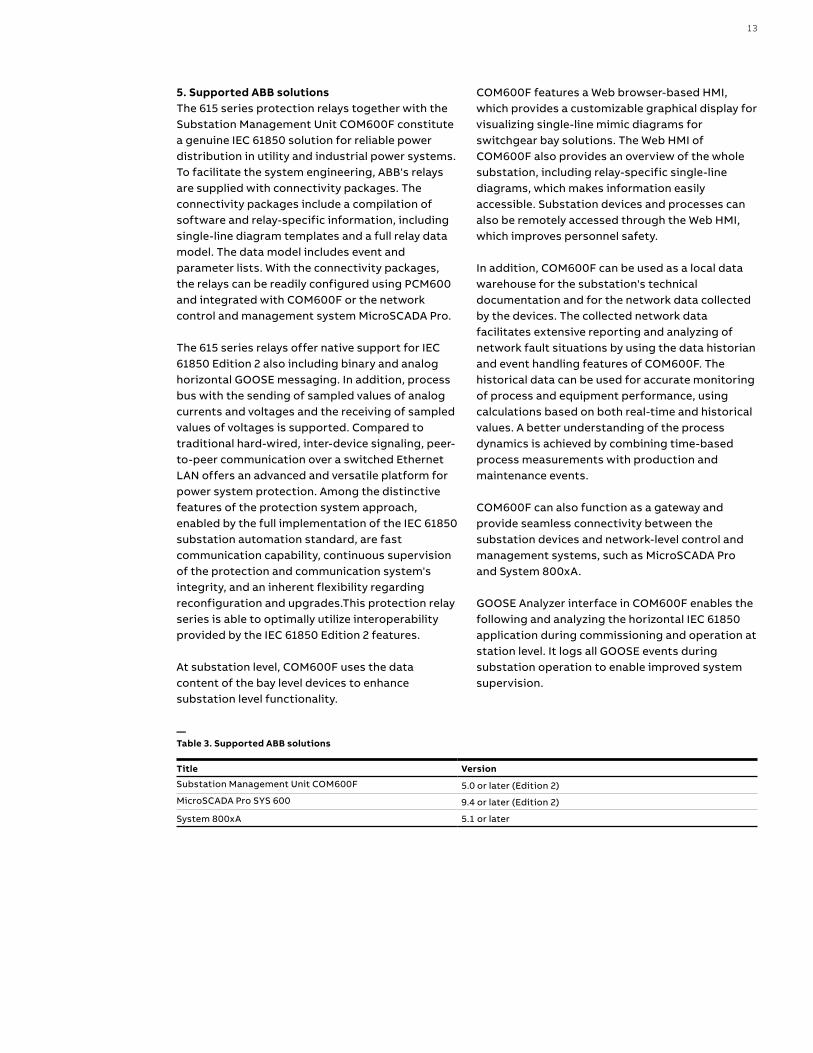
—Table 3. Supported ABB solutions
Title Version
Substation Management Unit COM600F 5.0 or later (Edition 2)
MicroSCADA Pro SYS 600 9.4 or later (Edition 2)
System 800xA 5.1 or later

14
PCM600Ethernet switch
Utility: IEC 60870-5-104Industry: OPC
COM600FWeb HMI
ABBMicroSCADA Pro/
System 800xA
Analog and binary horizontal GOOSE communication IEC 61850
PCM600Ethernet switch
COM600FWeb HMI
Analog and binary horizontal GOOSE communication IEC 61850
14 R E D 61 5 L I N E D I FFER ENTI A L PR OTEC TI O N A N D CO NTR O L
6. ControlRED615 integrates functionality for the control of a circuit breaker via the front panel HMI or by means of remote controls. In addition to the circuit-breaker control the relay features two control blocks which are intended for motor-operated control of disconnectors or circuit breaker truck and for their position indications. Further, the relay offers one control block which is intended for motor-operated control of one grounding switch control and its position indication.
Two physical binary inputs and two physical binary outputs are needed in the relay for each controllable primary device taken into use. The number of unused binary inputs and binary outputs varies depending on the chosen standard configuration. Further, some standard configurations also offer optional hardware modules that increase the number of available binary inputs and outputs.
If the amount of available binary inputs or outputs of the chosen standard configuration is not sufficient, the standard configuration can be modified to release some binary inputs or outputs
Figure 5. ABB power system example using Relion relays, COM600F and MicroSCADA Pro/System 800xA
which have originally been configured for other purposes, when applicable, or an external input or output module such as RIO600 can be integrated to the relay. The binary inputs and outputs of the external I/O module can be used for the less time critical binary signals of the application. The integration enables the releasing of some initially reserved binary inputs and outputs of the relay in the standard configuration.
The suitability of the relay's binary outputs which have been selected for controlling of primary devices should be carefully verified, for example, the make and carry as well as the breaking capacity should be considered. In case the requirements for the control-circuit of the primary device are not met, the use of external auxiliary relays should be considered.
The large graphical LCD of the relay's HMI includes a single-line diagram (SLD) with position indication for the relevant primary devices. Interlocking schemes required by the application are configured using the signal matrix or the application configuration functionality of PCM600.

15
7. MeasurementsThe relay continuously measures the phase currents, the symmetrical components of the currents and the residual current. If the relay includes voltage measurements, it also measures the residual voltage. The relay also calculates the demand value of the current over a user-selectable, pre-set time frame, the thermal overload of the protected object, and the phase unbalance based on the ratio between the negativesequence and positive-sequence current. Furthermore, the relay monitors the phase differential, bias and remote-end phase currents. The measured values can be accessed via the local HMI or remotely via the communication interface of the relay. The values can also be accessed locally or remotely using the Web HMI.
The relay is provided with a load profile recorder. The load profile feature stores the historical load data captured at a periodical time interval (demand interval). The records are in COMTRADE format.
8. Power qualityIn the EN standards, power quality is defined through the characteristics of the supply voltage. Transients, short-duration and long-duration voltage variations and unbalance and waveform distortions are the key characteristics describing power quality. The distortion monitoring functions are used for monitoring the current total demand distortion and the voltage total harmonic distortion. Power quality monitoring is an essential service that utilities can provide for their industrial and key customers. A monitoring system can provide information about system disturbances and their possible causes. It can also detect problem conditions throughout the system before they cause customer complaints, equipment malfunctions and even equipment damage or failure. Power quality problems are not limited to the utility side of the system. In fact, the majority of power quality problems are localized within customer facilities. Thus, power quality monitoring is not only an effective customer service strategy but also a way to protect a utility's reputation for quality power and service.
The protection relay has the following power quality monitoring functions.• Voltage variation• Voltage unbalance• Current harmonics• Voltage harmonics
The voltage unbalance and voltage variation functions are used for measuring short-duration voltage variations and monitoring voltage unbalance conditions in power transmission and distribution networks.
The voltage and current harmonics functions provide a method for monitoring the power quality by means of the current waveform distortion and voltage waveform distortion. The functions provides a short-term three-second average and a long-term demand for total demand distortion TDD and total harmonic distortion THD.
9. Fault location RED615 features an optional impedance-measuring fault location function suitable for locating short-circuits in radial distribution systems. Ground faults can be located in effectively and low-resistance grounded networks. Under circumstances where the fault current magnitude is at least of the same order of magnitude or higher than the load current, ground faults can also be located in isolated neutral distribution networks. The fault location function identifies the type of the fault and then calculates the distance to the fault point. An estimate of the fault resistance value is also calculated. The estimate provides information about the possible fault cause and the accuracy of the estimated distance to the fault point. 10. Disturbance recorderThe relay is provided with a disturbance recorder featuring up to 12 analog and 64 binary signal channels. The analog channels can be set to record either the waveform or the trend of the currents and voltages measured.
The analog channels can be set to trigger the recording function when the measured value falls below or exceeds the set values. The binary signal channels can be set to start a recording either on the rising or the falling edge of the binary signal or on both.
By default, the binary channels are set to record external or internal relay signals, for example, the start or trip signals of the relay stages, or external blocking or control signals. Binary relay signals, such as protection start and trip signals, or an external relay control signal via a binary input, can be set to trigger the recording. Recorded information is stored in a non-volatile memory and can be uploaded for subsequent fault analysis.
16
1024
PROCESS LEVELUSER LEVEL
Fault summary; Trip timestamp, Function, Currents, Voltages, etc.
BA
SIC
FU
NC
TIO
NS
IEC
618
50-8
-1M
odbu
sIE
C 1
03D
NP3
LHM
IW
HM
IPC
M60
0 Process events (FIFO)
128
Fault records (FIFO)
System and security-related events;Configuration changes, Control, Login, etc.
2048
Audittrailevents(FIFO)
n…100
Disturbance records
...7 yrs
Load profile record
Historical load data captured at a periodical time interval (Demand interval 1 ...180min)
Function specific data
Min/max demand currents, Operation counters, etc. History view
16 R E D 61 5 L I N E D I FFER ENTI A L PR OTEC TI O N A N D CO NTR O L
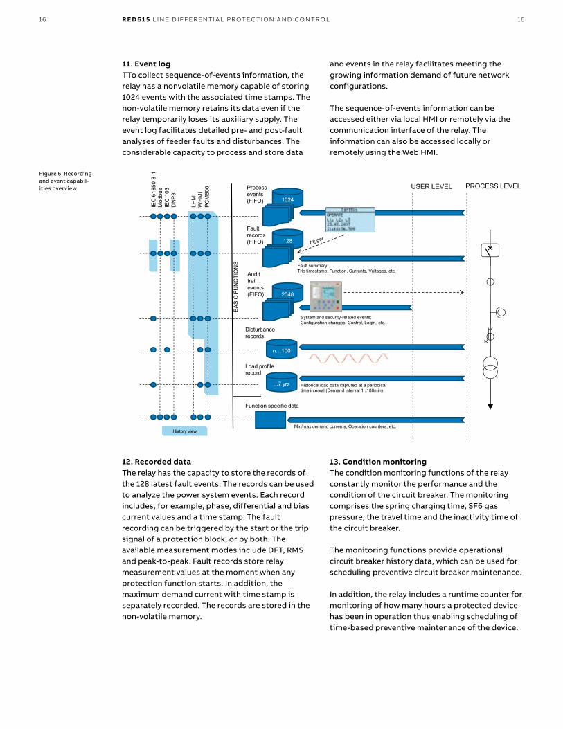
11. Event logTTo collect sequence-of-events information, the relay has a nonvolatile memory capable of storing 1024 events with the associated time stamps. The non-volatile memory retains its data even if the relay temporarily loses its auxiliary supply. The event log facilitates detailed pre- and post-fault analyses of feeder faults and disturbances. The considerable capacity to process and store data
Figure 6. Recording and event capabil-ities overview
and events in the relay facilitates meeting the growing information demand of future network configurations.
The sequence-of-events information can be accessed either via local HMI or remotely via the communication interface of the relay. The information can also be accessed locally or remotely using the Web HMI.
12. Recorded dataThe relay has the capacity to store the records of the 128 latest fault events. The records can be used to analyze the power system events. Each record includes, for example, phase, differential and bias current values and a time stamp. The fault recording can be triggered by the start or the trip signal of a protection block, or by both. The available measurement modes include DFT, RMS and peak-to-peak. Fault records store relay measurement values at the moment when any protection function starts. In addition, the maximum demand current with time stamp is separately recorded. The records are stored in the non-volatile memory.
13. Condition monitoringThe condition monitoring functions of the relay constantly monitor the performance and the condition of the circuit breaker. The monitoring comprises the spring charging time, SF6 gas pressure, the travel time and the inactivity time of the circuit breaker.
The monitoring functions provide operational circuit breaker history data, which can be used for scheduling preventive circuit breaker maintenance.
In addition, the relay includes a runtime counter for monitoring of how many hours a protected device has been in operation thus enabling scheduling of time-based preventive maintenance of the device.
17
14. Trip-circuit supervisionThe trip-circuit supervision continuously monitors the availability and operability of the trip circuit. It provides open circuit monitoring both when the circuit breaker is in its closed and in its open position. It also detects loss of circuit-breaker control voltage.
15. Self-supervisionThe relay’s built-in self-supervision system continuously monitors the state of the relay hardware and the operation of the relay software. Any fault or malfunction detected is used for alerting the operator. A permanent relay fault blocks the protection functions to prevent incorrect operation.
16. Current circuit supervision The relay includes current circuit supervision. Current circuit supervision is used for detecting faults in the current transformer secondary circuits. On detecting of a fault the current circuit supervision function activates an alarm LED and blocks the line differential protection and negative-sequence overcurrent protection functions to avoid unintended operation. The current circuit supervision function calculates the sum of the phase currents from the protection cores and compares the sum with the measured single reference current from a core balance current transformer or from separate cores in the phase current transformers.
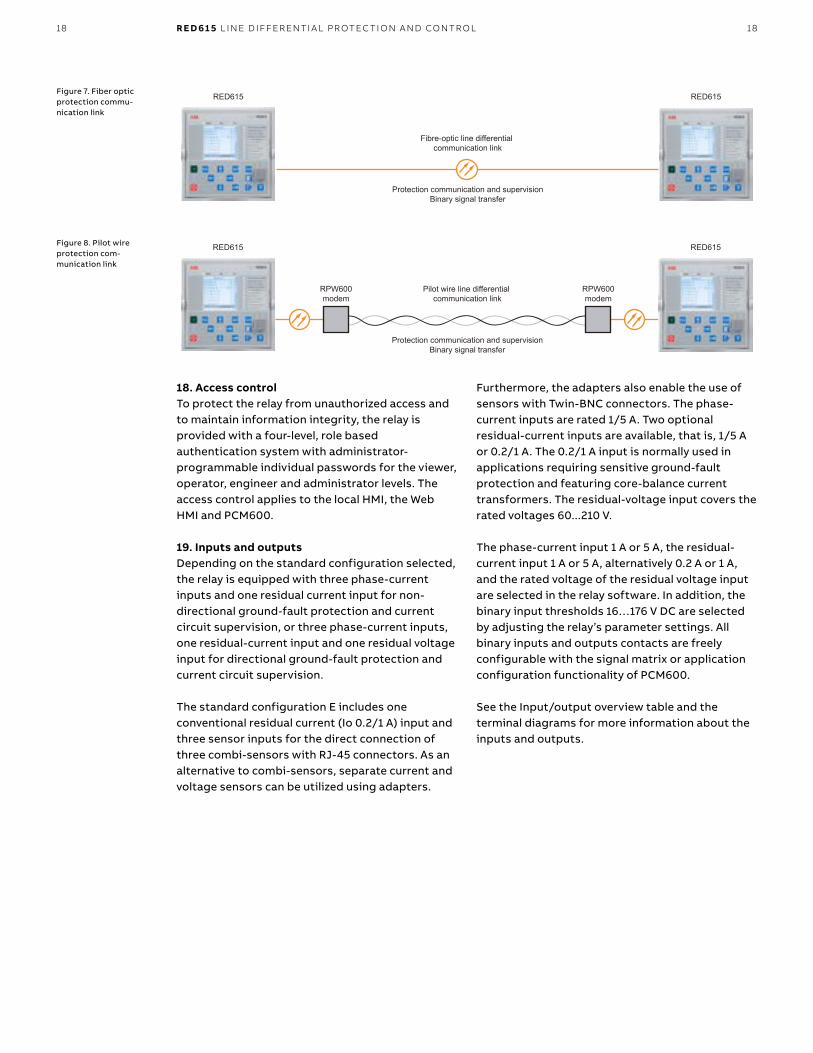
17. Protection communication and supervisionThe communication between the relays is enabled by means of a dedicated fiber optic communication channel. 1310 nm multimode or single-mode fibers with LC connectors are used for line differential communication. The channel is used for transferring the phase segregated current value data between the relays. The current phasors from the two relays, geographically located apart from each other, must be time coordinated so that the current differential algorithm can be executed correctly. The so called echo method is used for time synchronization. No external devices such as GPS clocks are thereby needed for the line differential protection communication.
As an option to the fiber optic communication link a galvanic connection over a pilot wire link composed of a twisted pair cable and RPW600 link-end communication modems can be established. The optional pilot wire communication link is also an ideal and cost efficient retrofit solution for electromechanical line differential protection installations. Compared to conventional combined
sequence line differential protection solutions with analog pilot wire communication, RED615 relays in combination with RPW600 communication modems offer a modern phase-segregated line differential protection solution over existing pilot wire cables.
The pilot wire link supports the same protection and communication functionality as the fiber optic link. The quality of service (QoS) is indicated by the modems and the communication link is continuously supervised by the relay. The RPW600 modem offers a 5 kV (RMS) level of isolation between the pilot wire terminals and ground. The RPW600 modems (master and follower) are galvanically connected to either end of the pilot wire and optically connected to the relays using short optical single-mode cables. Using 0.8 mm2 twisted pair cables pilot wire link distances up to 8 km are typically supported. However, twisted pair pilot wire cables in good conditions may support even longer distances to be covered. The length of the supported pilot wire link also depends on the noise environment in the installation. Should the need arise to replace the pilot wire cables with fiber optic cables, the single mode fiber optic LC connectors of the relays can be utilized for direct connection of the fiber optic communication link.
Apart from the continued protection communication, the communication channel can also be used for binary signal transfer (BST) that is, transferring of user configurable binary information between the relays. There are a total of eight BST signals available for user definable purposes. The BST signals can originate from the relay’s binary inputs or internal logics, and be assigned to the remote relay’s binary outputs or internal logics.
The protection communication supervision continuously monitors the protection communication link. The relay immediately blocks the line differential protection function in case that severe interference in the communication link, risking the correct operation of the function, is detected. An alarm signal will eventually be issued if the interference, indicating permanent failure in the protection communication, persists. The two high-set stages of the overcurrent protection are further by default released.
18
RED615 RED615
Fibre-optic line differential communication link
Protection communication and supervisionBinary signal transfer
RED615 RED615
Pilot wire line differential communication link
Protection communication and supervisionBinary signal transfer
RPW600modem
RPW600modem
18 R E D 61 5 L I N E D I FFER ENTI A L PR OTEC TI O N A N D CO NTR O L
18. Access controlTo protect the relay from unauthorized access and to maintain information integrity, the relay is provided with a four-level, role based authentication system with administrator-programmable individual passwords for the viewer, operator, engineer and administrator levels. The access control applies to the local HMI, the Web HMI and PCM600.
19. Inputs and outputsDepending on the standard configuration selected, the relay is equipped with three phase-current inputs and one residual current input for non-directional ground-fault protection and current circuit supervision, or three phase-current inputs, one residual-current input and one residual voltage input for directional ground-fault protection and current circuit supervision.
The standard configuration E includes one conventional residual current (Io 0.2/1 A) input and three sensor inputs for the direct connection of three combi-sensors with RJ-45 connectors. As an alternative to combi-sensors, separate current and voltage sensors can be utilized using adapters.
Furthermore, the adapters also enable the use of sensors with Twin-BNC connectors. The phase-current inputs are rated 1/5 A. Two optional residual-current inputs are available, that is, 1/5 A or 0.2/1 A. The 0.2/1 A input is normally used in applications requiring sensitive ground-fault protection and featuring core-balance current transformers. The residual-voltage input covers the rated voltages 60...210 V.
The phase-current input 1 A or 5 A, the residual-current input 1 A or 5 A, alternatively 0.2 A or 1 A, and the rated voltage of the residual voltage input are selected in the relay software. In addition, the binary input thresholds 16…176 V DC are selected by adjusting the relay’s parameter settings. All binary inputs and outputs contacts are freely configurable with the signal matrix or application configuration functionality of PCM600. See the Input/output overview table and the terminal diagrams for more information about the inputs and outputs.
Figure 7. Fiber optic protection commu-nication link
Figure 8. Pilot wire protection com-munication link

19
20. Station communicationThe relay supports a range of communication protocols including IEC 61850 Edition 2, IEC 61850-9-2 LE, Modbus® and DNP3. Operational information and controls are available through these protocols. However, some communication functionality, for example, horizontal communication between the relays, is only enabled by the IEC 61850 communication protocol. The IEC 61850 protocol is a core part of the relay as the protection and control application is fully based on standard modelling. The relay supports Edition 2 and Edition 1 versions of the standard. With Edition 2 support, the relay has the latest functionality modelling for substation applications and the best interoperability for modern substations. It incorporates also the full support of standard device mode functionality supportingdifferent test applications. Control applications can utilize the new safe and advanced station control authority feature.
The IEC 61850 communication implementation supports monitoring and control functions. Additionally, parameter settings, disturbance recordings and fault records can be accessed using the IEC 61850 protocol. Disturbance recordings are available to any Ethernet-based application in the standard COMTRADE file format. The relay supports simultaneous event reporting to five different clients on thestation bus. The relay can exchange data with other devices using the IEC 61850 protocol.
The relay can send binary and analog signals to other devices using the IEC 61850-8-1 GOOSE (Generic Object Oriented Substation Event) profile. Binary GOOSE messaging can, for example, be employed for protection and interlocking-based protection schemes. The relay meets the GOOSE performance requirements for tripping
applications in distribution substations, as defined by the IEC 61850 standard (<10 ms data exchange between the devices). The relay also supports the sending and receiving of analog values using GOOSE messaging. Analog GOOSE messaging enables easy transfer of analog measurement values over the station bus, thus facilitating for example the sending of measurement values between the relays when controlling parallel running transformers.
The relay also supports IEC 61850 process bus by sending sampled values of analog currents and voltages and by receiving sampled values of voltages. With this functionality the galvanic interpanel wiring can be replaced with Ethernet communication. The measured values are transferred as sampled values using IEC 61850-9-2 LE protocol. The intended application for sampled values shares the voltages to other 615 series relays, having voltage based functions and 9-2 support. 615 relays with process bus based applications use IEEE 1588 for high accuracy time synchronization. For redundant Ethernet communication, the relay offers two optical Ethernet network interfaces. Ethernet network redundancy can be achieved using the high-availability seamless redundancy (HSR) protocol or the parallel redundancy protocol (PRP) or a with self-healing ring using RSTP in managed switches. Ethernet redundancy can be applied to Ethernet-based IEC 61850, Modbus and DNP3 protocols.
All communication card variants support self-healing ring based Ethernet redundancy. Communication card variants with two optical interfaces for station bus communication have support for HSR and PRP redundancy protocols. These variants include also support for IEEE 1588 based time synchronization.
—Table 4. Input/output overview
Std. conf.
Order code digit Analog channels Binary channels
5-6 7-8 CT VTCombi-sensor
BI BO RTD mA
DAE/AF AG 4 5 16 4 PO + 6 SO - -
FE/FF AD 4 5 12 4 PO + 6 SO 2 1
E DA AH 1 - 3 8 4 PO + 6 SO - -
20
Ethernet switchIEC 61850 PRPEthernet switch
REF615 REF620 RET620 REM620 REF615
SCADACOM600
20 R E D 61 5 L I N E D I FFER ENTI A L PR OTEC TI O N A N D CO NTR O L
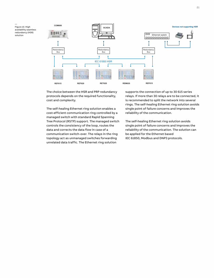
HSR applies the PRP principle of parallel operation to a single ring. For each message sent, the node sends two frames, one through each port. Both the frames circulate in opposite directions over the ring. Every node forwards the frames it receives from one port to another to reach the next node. When the originating sender node receives the
Figure 9. Parallel redundancy proto-col (PRP) solution
frame it sent, the sender node discards the frame to avoid loops. The HSR ring with 615 series relays supports the connection of up to 30 relays. If more than 30 relays are to be connected, it is recommended to split the network into several rings to guarantee the performance for real-time applications.
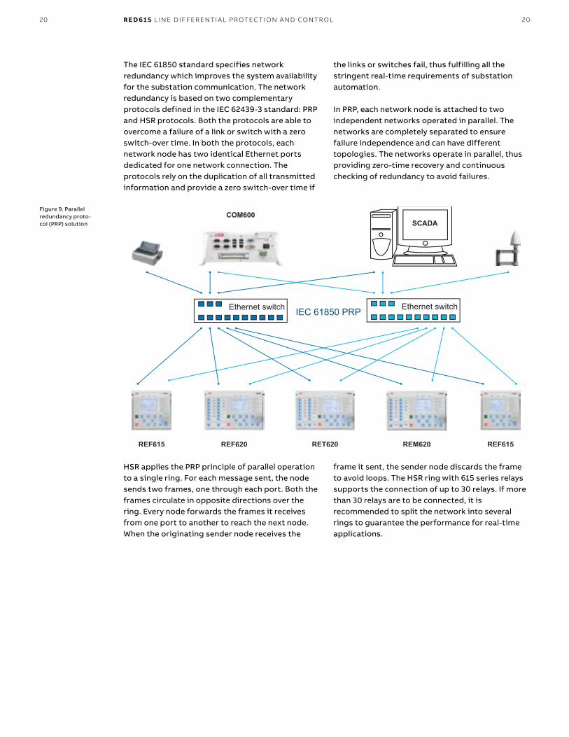
The IEC 61850 standard specifies network redundancy which improves the system availability for the substation communication. The network redundancy is based on two complementary protocols defined in the IEC 62439-3 standard: PRP and HSR protocols. Both the protocols are able to overcome a failure of a link or switch with a zero switch-over time. In both the protocols, each network node has two identical Ethernet ports dedicated for one network connection. The protocols rely on the duplication of all transmitted information and provide a zero switch-over time if
the links or switches fail, thus fulfilling all the stringent real-time requirements of substation automation.
In PRP, each network node is attached to two independent networks operated in parallel. The networks are completely separated to ensure failure independence and can have different topologies. The networks operate in parallel, thus providing zero-time recovery and continuous checking of redundancy to avoid failures.
21
Ethernet switch
RedundancyBox
IEC 61850 HSR
RedundancyBox
RedundancyBox
REF615 REF620 RET620 REM620 REF615
SCADA Devices not supporting HSRCOM600
The choice between the HSR and PRP redundancy protocols depends on the required functionality, cost and complexity.
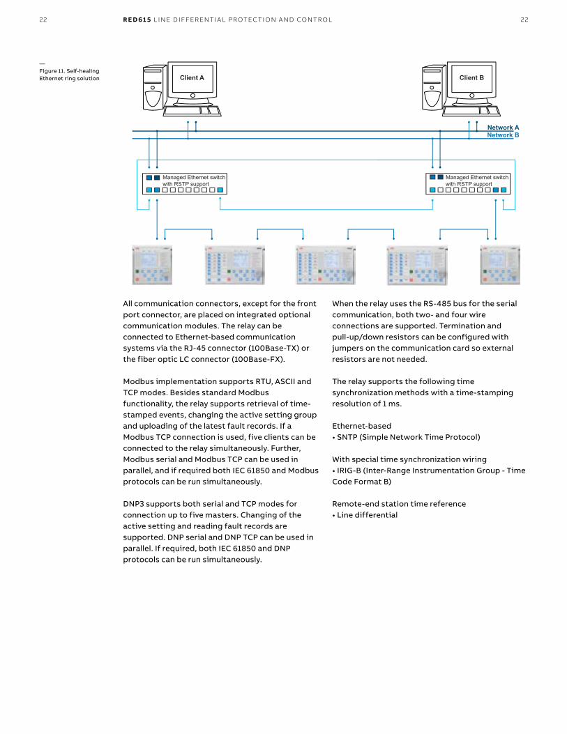
The self-healing Ethernet ring solution enables a cost-efficient communication ring controlled by a managed switch with standard Rapid Spanning Tree Protocol (RSTP) support. The managed switch controls the consistency of the loop, routes the data and corrects the data flow in case of a communication switch-over. The relays in the ring topology act as unmanaged switches forwarding unrelated data traffic. The Ethernet ring solution
—Figure 10. High availability seamless redundancy (HSR) solution
supports the connection of up to 30 615 series relays. If more than 30 relays are to be connected, it is recommended to split the network into several rings. The self-healing Ethernet ring solution avoids single point of failure concerns and improves the reliability of the communication.
The self-healing Ethernet ring solution avoids single point of failure concerns and improves the reliability of the communication. The solution can be applied for the Ethernet basedIEC 61850, Modbus and DNP3 protocols.
22
Managed Ethernet switchwith RSTP support
Managed Ethernet switchwith RSTP support
Client BClient A
Network ANetwork B
22 R E D 61 5 L I N E D I FFER ENTI A L PR OTEC TI O N A N D CO NTR O L
All communication connectors, except for the front port connector, are placed on integrated optional communication modules. The relay can be connected to Ethernet-based communication systems via the RJ-45 connector (100Base-TX) or the fiber optic LC connector (100Base-FX).
Modbus implementation supports RTU, ASCII and TCP modes. Besides standard Modbus functionality, the relay supports retrieval of time-stamped events, changing the active setting group and uploading of the latest fault records. If a Modbus TCP connection is used, five clients can be connected to the relay simultaneously. Further, Modbus serial and Modbus TCP can be used in parallel, and if required both IEC 61850 and Modbus protocols can be run simultaneously.
DNP3 supports both serial and TCP modes for connection up to five masters. Changing of the active setting and reading fault records are supported. DNP serial and DNP TCP can be used in parallel. If required, both IEC 61850 and DNP protocols can be run simultaneously.
—Figure 11. Self-healing Ethernet ring solution
When the relay uses the RS-485 bus for the serial communication, both two- and four wire connections are supported. Termination and pull-up/down resistors can be configured with jumpers on the communication card so external resistors are not needed.
The relay supports the following time synchronization methods with a time-stamping resolution of 1 ms.
Ethernet-based • SNTP (Simple Network Time Protocol)
With special time synchronization wiring• IRIG-B (Inter-Range Instrumentation Group - Time Code Format B)
Remote-end station time reference• Line differential
23
The relay supports the following high accuracy time synchronization method with a time-stamping resolution of 4 μs required especially in process bus applications.• PTP (IEEE 1588) v2 with Power Profile
The IEEE 1588 support is included in all variants having a redundant Ethernet communication module.
IEEE 1588 v2 features• Ordinary Clock with Best Master Clock algorithm• One-step Transparent Clock for Ethernet ring topology• 1588 v2 Power Profile• Receive (slave): 1-step/2-step• Transmit (master): 1-step
• Layer 2 mapping• Peer to peer delay calculation• Multicast operation
Required accuracy of grandmaster clock is +/-1 μs. The relay can work as a master clock per BMC algorithm if the external grandmaster clock is not available for short term.
The IEEE 1588 support is included in all variants having a redundant Ethernet communication module.
In addition, the relay supports time synchronization via Modbus, and DNP3 serial communication protocols.
—Table 5. Supported station communication interfaces and protocols
Interfaces/Protocols Ethernet Serial
100BASE-TX RJ-45 100BASE-FX LC RS-232/RS-485 Fiber optic ST
IEC 61850-8-1 • • - -
IEC 61850-9-2 LE • • - -
MODBUS RTU/ASCII - - • •
MODBUS TCP/IP • • - -
DNP3 (serial) - - • •
DNP3 TCP/IP • • - -
—• = Supported
2424 R E D 61 5 L I N E D I FFER ENTI A L PR OTEC TI O N A N D CO NTR O L
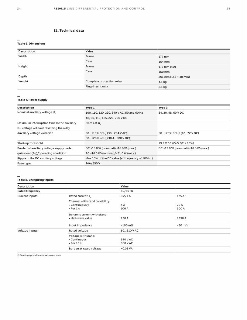
—Table 6. Dimensions
Description Value
Width Frame 177 mm
Case 164 mm
Height Frame 177 mm (4U)
Case 160 mm
Depth 201 mm (153 + 48 mm)
Weight Complete protection relay 4.1 kg
Plug-in unit only 2.1 kg
21. Technical data
—Table 7. Power supply
Description Type 1 Type 2
Nominal auxiliary voltage Un 100, 110, 120, 220, 240 V AC, 50 and 60 Hz 24, 30, 48, 60 V DC
48, 60, 110, 125, 220, 250 V DC
Maximum interruption time in the auxiliary 50 ms at Un
DC voltage without resetting the relay
Auxiliary voltage variation 38...110% of Un (38...264 V AC) 50...120% of Un (12...72 V DC)
80...120% of Un (38.4...300 V DC)
Start-up threshold 19.2 V DC (24 V DC × 80%)
Burden of auxiliary voltage supply under DC <13.0 W (nominal)/<18.0 W (max.) DC <13.0 W (nominal)/<18.0 W (max.)
quiescent (Pq)/operating condition AC <16.0 W (nominal)/<21.0 W (max.)
Ripple in the DC auxiliary voltage Max 15% of the DC value (at frequency of 100 Hz)
Fuse type T4A/250 V
—Table 8. Energizing inputs
Description Value
Rated frequency 50/60 Hz
Current inputs Rated current, In 0.2/1 A 1/5 A1)
Thermal withstand capability: • Continuously • For 1 s
4 A 100 A
20 A 500 A
Dynamic current withstand: • Half-wave value
250 A
1250 A
Input impedance <100 mΩ <20 mΩ
Voltage inputs Rated voltage 60...210 V AC
Voltage withstand: • Continuous • For 10 s
240 V AC 360 V AC
Burden at rated voltage <0.05 VA
1) Ordering option for residual current input
25
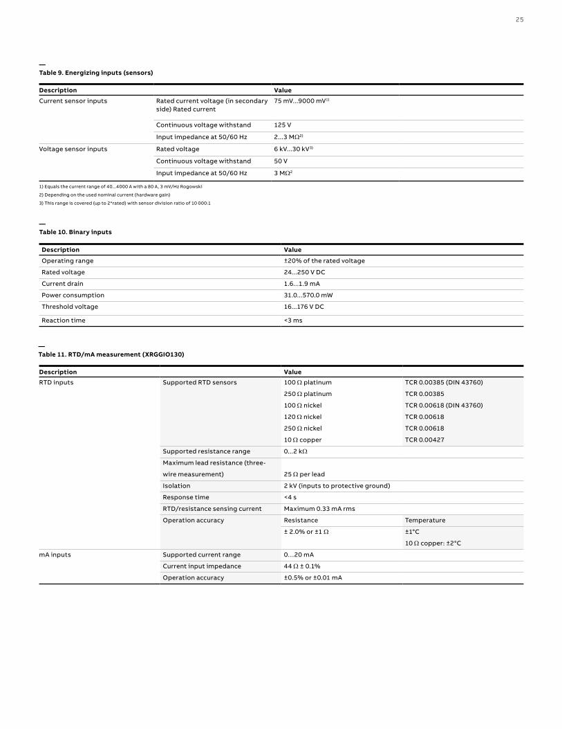
—Table 10. Binary inputs
Description Value
Operating range ±20% of the rated voltage
Rated voltage 24...250 V DC
Current drain 1.6...1.9 mA
Power consumption 31.0...570.0 mW
Threshold voltage 16...176 V DC
Reaction time <3 ms
—Table 11. RTD/mA measurement (XRGGIO130)
Description Value
RTD inputs Supported RTD sensors 100 Ω platinum TCR 0.00385 (DIN 43760)
250 Ω platinum TCR 0.00385
100 Ω nickel TCR 0.00618 (DIN 43760)
120 Ω nickel TCR 0.00618
250 Ω nickel TCR 0.00618
10 Ω copper TCR 0.00427
Supported resistance range 0...2 kΩ
Maximum lead resistance (three-
wire measurement) 25 Ω per lead
Isolation 2 kV (inputs to protective ground)
Response time <4 s
RTD/resistance sensing current Maximum 0.33 mA rms
Operation accuracy Resistance Temperature
± 2.0% or ±1 Ω ±1°C
10 Ω copper: ±2°C
mA inputs Supported current range 0…20 mA
Current input impedance 44 Ω ± 0.1%
Operation accuracy ±0.5% or ±0.01 mA
—Table 9. Energizing inputs (sensors)
Description Value
Current sensor inputs Rated current voltage (in secondaryside) Rated current
75 mV...9000 mV1)
Continuous voltage withstand 125 V
Input impedance at 50/60 Hz 2...3 MΩ2)
Voltage sensor inputs Rated voltage 6 kV...30 kV3)
Continuous voltage withstand 50 V
Input impedance at 50/60 Hz 3 MΩ2
1) Equals the current range of 40...4000 A with a 80 A, 3 mV/Hz Rogowski
2) Depending on the used nominal current (hardware gain)
3) This range is covered (up to 2*rated) with sensor division ratio of 10 000:1

26 R E D 61 5 L I N E D I FFER ENTI A L PR OTEC TI O N A N D CO NTR O L
—Table 13. Signal outputs and IRF output
—Table 14. Double-pole power output relays with TCS function
—Table 15. Single-pole power output relays
Description Value
Rated voltage 250 V AC/DC
Continuous contact carry 5 A
Make and carry for 3.0 s 10 A
Make and carry 0.5 s 15 A
Breaking capacity when the control-circuit time constant L/R<40 ms, at 48/110/220 V DC
1 A/0.25 A/0.15 A
Minimum contact load 10 mA at 5 V AC/DC
Description Value
Rated voltage 250 V AC/DC
Continuous contact carry 8 A
Make and carry for 3.0 s 15 A
Make and carry for 0.5 s 30 A
Breaking capacity when the control-circuit time constant L/R<40 ms, at 48/110/220 V DC (two contacts connected in series) 5 A/3 A/1 A
Minimum contact load 100 mA at 24 V AC/DC
Trip-circuit supervision (TCS):1) Control voltage range2) Current drain through the supervision circuit3) Minimum voltage over the TCS contact
20...250 V AC/DC~1.5 mA20 V AC/DC (15...20 V)
Description Value
Rated voltage 250 V AC/DC
Continuous contact carry 8 A
Make and carry for 3.0 s 15 A
Make and carry for 0.5 s 30 A
Breaking capacity when the control-circuit time constant L/R<40 ms, at 48/110/220 V DC
5 A/3 A/1 A
Minimum contact load 100 mA at 24 V AC/DC
—Table 12. Signal output X100: SO1
Description Value
Rated voltage 250 V AC/DC
Continuous contact carry 5 A
Make and carry for 3.0 s 15 A
Make and carry for 0.5 s 30 A
Breaking capacity when the control-circuit time constant L/R<40 ms 1 A/0.25 A/0.15 A
Minimum contact load 100 mA at 24 V AC/DC
27
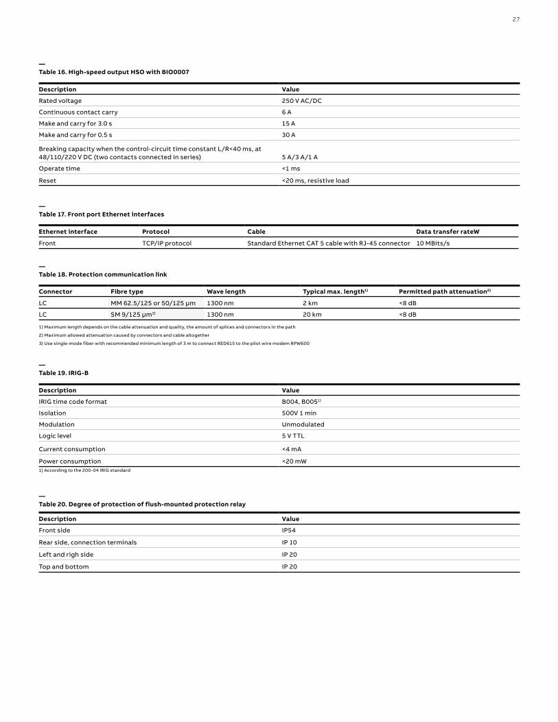
—Table 16. High-speed output HSO with BIO0007
Description Value
Rated voltage 250 V AC/DC
Continuous contact carry 6 A
Make and carry for 3.0 s 15 A
Make and carry for 0.5 s 30 A
Breaking capacity when the control-circuit time constant L/R<40 ms, at 48/110/220 V DC (two contacts connected in series) 5 A/3 A/1 A
Operate time <1 ms
Reset <20 ms, resistive load
—Table 17. Front port Ethernet interfaces
Ethernet interface Protocol Cable Data transfer rateW
Front TCP/IP protocol Standard Ethernet CAT 5 cable with RJ-45 connector 10 MBits/s
—Table 19. IRIG-B
Description Value
IRIG time code format B004, B0051)
Isolation 500V 1 min
Modulation Unmodulated
Logic level 5 V TTL
Current consumption <4 mA
Power consumption <20 mW1) According to the 200-04 IRIG standard
—Table 20. Degree of protection of flush-mounted protection relay
Description Value
Front side IP54
Rear side, connection terminals IP 10
Left and righ side IP 20
Top and bottom IP 20
—Table 18. Protection communication link
Connector Fibre type Wave length Typical max. length1) Permitted path attenuation2)
LC MM 62.5/125 or 50/125 μm 1300 nm 2 km <8 dB
LC SM 9/125 μm3) 1300 nm 20 km <8 dB
1) Maximum length depends on the cable attenuation and quality, the amount of splices and connectors in the path
2) Maximum allowed attenuation caused by connectors and cable altogether
3) Use single-mode fiber with recommended minimum length of 3 m to connect RED615 to the pilot wire modem RPW600

28 R E D 61 5 L I N E D I FFER ENTI A L PR OTEC TI O N A N D CO NTR O L
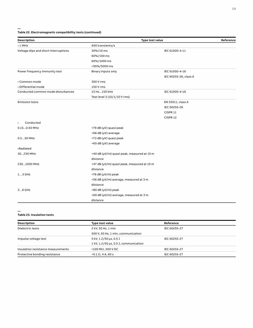
—Table 22. Electromagnetic compatibility tests
Description Type test value Reference
1 MHz/100 kHz burst disturbance test IEC 61000-4-18
IEC 60255-26, class III
IEEE C37.90.1-2002
• Common mode 2.5 kV
• Differential mode 2.5 kV
3 MHz, 10 MHz and 30 MHz burst disturbance test IEC 61000-4-18
IEC 60255-26, class III
• Common mode 2.5 kV
Electrostatic discharge test IEC 61000-4-2
IEC 60255-26
IEEE C37.90.3-2001
• Contact discharge 8 kV
• Air discharge 15 kV
Radio frequency interference test
10 V (rms) IEC 61000-4-6
f = 150 kHz...80 MHz IEC 60255-26, class III
10 V/m (rms) IEC 61000-4-3
f = 80...2700 MHz IEC 60255-26, class III
10 V/m ENV 50204
f = 900 MHz IEC 60255-26, class III
20 V/m (rms) IEEE C37.90.2-2004
f = 80...1000 MHz
Fast transient disturbance test IEC 61000-4-4
IEC 60255-26
IEEE C37.90.1-2002
• All ports 4 kV
Surge immunity test IEC 61000-4-5
IEC 60255-26
• Communication 1 kV, line-to-ground
• Other ports 4 kV, line-to-ground
2 kV, line-to-line
Power frequency (50 Hz) magnetic field immunity test IEC 61000-4-8
• Continuous 300 A/m
• 1...3 s 1000 A/m
Pulse magnetic field immunity test 1000 A/m IEC 61000-4-9
6.4/16 μs
Damped oscillatory magnetic field immunity test IEC 61000-4-10
• 2 s 100 A/m
1) Degradation in MTBF and HMI performance outside the temperature range of -25...+55 ºC
2) For relays with an LC communication interface the maximum operating temperature is +70 ºC
—Table 21. Environmental conditions
Description Value
Operating temperature range -25...+55ºC (continuous)
Short-time service temperature range -40...+70ºC (<16h)1)2)
Relative humidity <93%, non-condensing
Atmospheric pressure 86...106 kPa
Altitude Up to 2000 m
Transport and storage temperature range -40...+85ºC
29
—Table 23. Insulation tests
Description Type test value Reference
Dielectric tests 2 kV, 50 Hz, 1 min IEC 60255-27
500 V, 50 Hz, 1 min, communication
Impulse voltage test 5 kV, 1.2/50 μs, 0.5 J IEC 60255-27
1 kV, 1.2/50 μs, 0.5 J, communication
Insulation resistance measurements >100 MΩ, 500 V DC IEC 60255-27
Protective bonding resistance <0.1 Ω, 4 A, 60 s IEC 60255-27
—Table 22. Electromagnetic compatibility tests (continued)
Description Type test value Reference
• 1 MHz 400 transients/s
Voltage dips and short interruptions 30%/10 ms IEC 61000-4-11
60%/100 ms
60%/1000 ms
>95%/5000 ms
Power frequency immunity test Binary inputs only IEC 61000-4-16
IEC 60255-26, class A
• Common mode 300 V rms
• Differential mode 150 V rms
Conducted common mode disturbances 15 Hz...150 kHz IEC 61000-4-16
Test level 3 (10/1/10 V rms)
Emission tests EN 55011, class A
IEC 60255-26
CISPR 11
CISPR 12
• Conducted
0.15...0.50 MHz <79 dB (μV) quasi peak
<66 dB (μV) average
0.5...30 MHz <73 dB (μV) quasi peak
<60 dB (μV) average
•Radiated
30...230 MHz <40 dB (μV/m) quasi peak, measured at 10 m
distance
230...1000 MHz <47 dB (μV/m) quasi peak, measured at 10 m
distance
1…3 GHz <76 dB (μV/m) peak
<56 dB (μV/m) average, measured at 3 m
distance
3…6 GHz <80 dB (μV/m) peak
<60 dB (μV/m) average, measured at 3 m
distance
30 R E D 61 5 L I N E D I FFER ENTI A L PR OTEC TI O N A N D CO NTR O L
—Table 25. Environmental tests
Description Type test value Reference
Dry heat test • 96 h at +55ºC IEC 60068-2-2
• 16 h at -70ºC1)
Dry cold test • 96 h at -25ºC IEC 60068-2-1
• 16 h at -40ºC
Damp heat test • 6 cycles (12 h + 12 h) at +25°C…+55°C, IEC 60068-2-30
humidity >93%
Change of temperature test • 5 cycles (3 h + 3 h) IEC60068-2-14
at -25°C...+55°C
Storage test • 96 h at -40ºC IEC 60068-2-1
• 96 h at +85ºC IEC 60068-2-2
—Table 26. Product safety
Description Reference
LV directive 2006/95/EC
Standard EN 60255-27 (2013)
EN 60255-1 (2009)
—Table 27. EMC compliance Table 24. Product safety
Description Reference
EMC directive 2004/108/EC
Standard EN 60255-26 (2013)
—Table 28. RoHS compliance
Description
Complies with RoHS directive 2002/95/EC
1) For relays with an LC communication interface the maximum operating temperature is +70oC
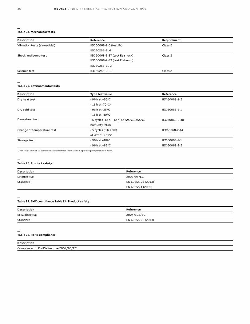
—Table 24. Mechanical tests
Description Reference Requirement
Vibration tests (sinusoidal) IEC 60068-2-6 (test Fc) Class 2
IEC 60255-21-1
Shock and bump test IEC 60068-2-27 (test Ea shock) Class 2
IEC 60068-2-29 (test Eb bump)
IEC 60255-21-2
Seismic test IEC 60255-21-3 Class 2
31
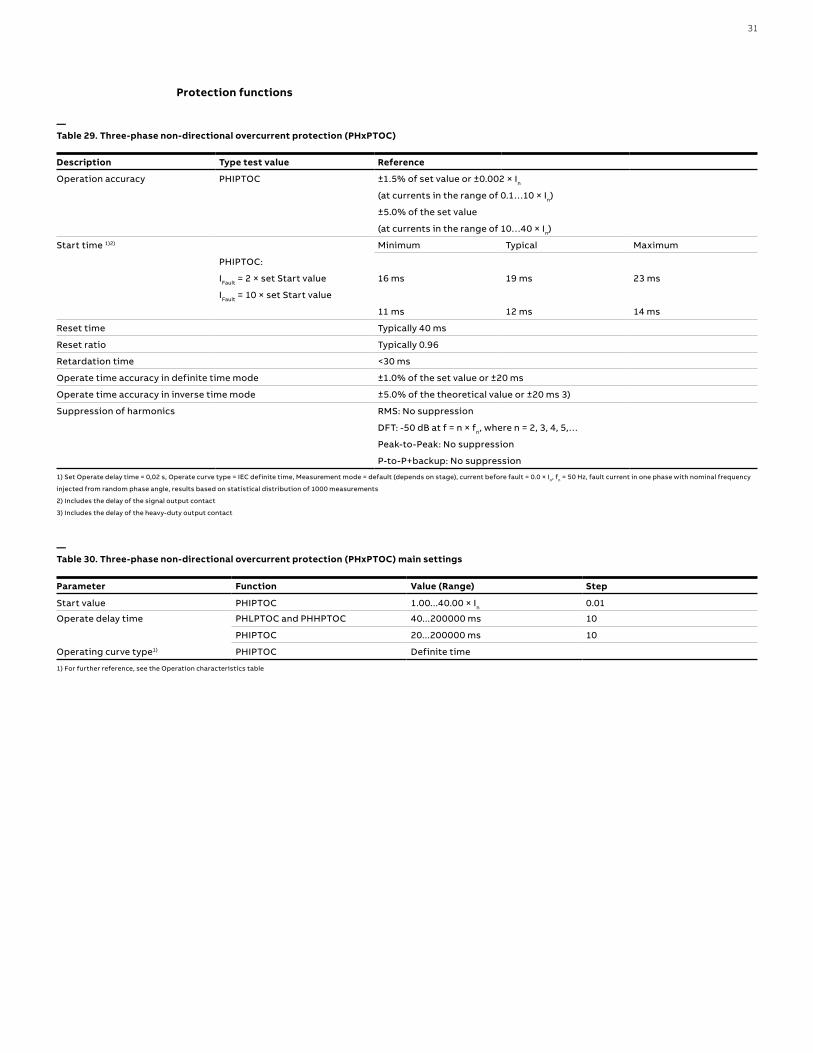
—Table 29. Three-phase non-directional overcurrent protection (PHxPTOC)
Description Type test value Reference
Operation accuracy PHIPTOC ±1.5% of set value or ±0.002 × In
(at currents in the range of 0.1…10 × In)
±5.0% of the set value
(at currents in the range of 10…40 × In)
Start time 1)2) Minimum Typical Maximum
PHIPTOC:
IFault = 2 × set Start value 16 ms 19 ms 23 ms
IFault = 10 × set Start value
11 ms 12 ms 14 ms
Reset time Typically 40 ms
Reset ratio Typically 0.96
Retardation time <30 ms
Operate time accuracy in definite time mode ±1.0% of the set value or ±20 ms
Operate time accuracy in inverse time mode ±5.0% of the theoretical value or ±20 ms 3)
Suppression of harmonics RMS: No suppression
DFT: -50 dB at f = n × fn, where n = 2, 3, 4, 5,…
Peak-to-Peak: No suppression
P-to-P+backup: No suppression
—Table 30. Three-phase non-directional overcurrent protection (PHxPTOC) main settings
Parameter Function Value (Range) Step
Start value PHIPTOC 1.00...40.00 × In 0.01
Operate delay time PHLPTOC and PHHPTOC 40...200000 ms 10
PHIPTOC 20...200000 ms 10
Operating curve type1) PHIPTOC Definite time
1) Set Operate delay time = 0,02 s, Operate curve type = IEC definite time, Measurement mode = default (depends on stage), current before fault = 0.0 × In, fn = 50 Hz, fault current in one phase with nominal frequency
injected from random phase angle, results based on statistical distribution of 1000 measurements
2) Includes the delay of the signal output contact
3) Includes the delay of the heavy-duty output contact
Protection functions
1) For further reference, see the Operation characteristics table
32 R E D 61 5 L I N E D I FFER ENTI A L PR OTEC TI O N A N D CO NTR O L
—Table 31. Three-phase directional overcurrent protection (DPHxPDOC)
Characteristic Value
Operation accuracy Depending on the frequency of the current/voltage measured: fn ±2 Hz
DPHLPDOC Current:
±1.5% of the set value or ±0.002 × In
Voltage:
±1.5% of the set value or ±0.002 × Un
Phase angle: ±2°
DPHHPDOC Current:
±1.5% of the set value or ±0.002 × In
(at currents in the range of 0.1…10 × In)
±5.0% of the set value
(at currents in the range of 10…40 × In)
Voltage:
±1.5% of the set value or ±0.002 × Un
Phase angle: ±2°
Start time1)2) Minimum Typical Maximum
IFault = 2.0 × set Start value 39 ms 43 ms 47 ms
Reset time Typically 40 ms
Reset ratio Typically 0.96
Retardation time <35 ms
Operate time accuracy in definite time mode ±1.0% of the set value or ±20 ms
Operate time accuracy in inverse time mode ±5.0% of the theoretical value or ±20 ms3)
Suppression of harmonics DFT: -50 dB at f = n × fn, where n = 2, 3, 4, 5,…
—Table 32. Three-phase directional overcurrent protection (DPHxPDOC) main settings
Parameter Function Value (Range) Step
Start value DPHLPDOC 0.05...5.00 × In 0.01
DPHHPDOC 0.10...40.00 × In 0.01
Time multiplier DPHxPDOC 0.05...15.00 0.01
Operate delay time DPHxPDOC 40...200000 ms 10
Directional mode DPHxPDOC 1 = Non-directional
2 = Forward
3 = Reverse
Characteristic angle DPHxPDOC -179...180° 1
Operating curve type1) DPHLPDOC Definite or inverse time
Curve type: 1, 2, 3, 4, 5, 6, 7, 8, 9, 10, 11, 12, 13, 14, 15, 17, 18, 19
DPHHPDOC Definite or inverse time
Curve type: 1, 3, 5, 9, 10, 12, 15, 17
1) Measurement mode and Pol quantity = default, current before fault = 0.0 × In, voltage before fault = 1.0 × Un, fn = 50 Hz, fault current in one phase with nominal frequency injected from
random phase angle, results based on statistical distribution of 1000 measurements
2) Includes the delay of the signal output contact
3) Maximum Start value = 2.5 × In, Start value multiples in range of 1.5...20
1) For further reference, see the Operating characteristics table
33
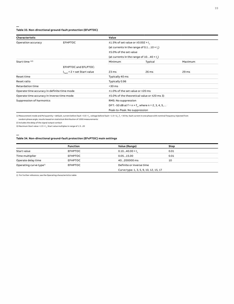
—Table 33. Non-directional ground-fault protection (EFxPTOC)
Characteristic Value
Operation accuracy EFHPTOC ±1.5% of set value or ±0.002 × In
(at currents in the range of 0.1…10 × In)
±5.0% of the set value
(at currents in the range of 10…40 × In)
Start time 1)2) Minimum Typical Maximum
EFHPTOC and EFLPTOC:
IFault = 2 × set Start value 23 ms 26 ms 29 ms
Reset time Typically 40 ms
Reset ratio Typically 0.96
Retardation time <30 ms
Operate time accuracy in definite time mode ±1.0% of the set value or ±20 ms
Operate time accuracy in inverse time mode ±5.0% of the theoretical value or ±20 ms 3)
Suppression of harmonics RMS: No suppression
DFT: -50 dB at f = n × fn, where n = 2, 3, 4, 5,…
Peak-to-Peak: No suppression
—Table 34. Non-directional ground-fault protection (EFxPTOC) main settings
Function Value (Range) Step
Start value EFHPTOC 0.10...40.00 × In 0.01
Time multiplier EFHPTOC 0.05...15.00 0.01
Operate delay time EFHPTOC 40...200000 ms 10
Operating curve type1) EFHPTOC Definite or inverse time
Curve type: 1, 3, 5, 9, 10, 12, 15, 17
1) Measurement mode and Pol quantity = default, current before fault = 0.0 × In, voltage before fault = 1.0 × Un, fn = 50 Hz, fault current in one phase with nominal frequency injected from
random phase angle, results based on statistical distribution of 1000 measurements
2) Includes the delay of the signal output contact
3) Maximum Start value = 2.5 × In, Start value multiples in range of 1.5...20
1) For further reference, see the Operating characteristics table
34 R E D 61 5 L I N E D I FFER ENTI A L PR OTEC TI O N A N D CO NTR O L
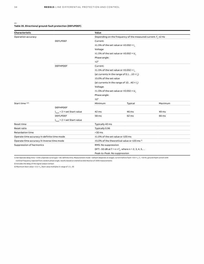
—Table 35. Directional ground-fault protection (DEFxPDEF)
Characteristic Value
Operation accuracy Depending on the frequency of the measured current: fn ±2 Hz
DEFLPDEF Current:
±1.5% of the set value or ±0.002 × In
Voltage
±1.5% of the set value or ±0.002 × Un
Phase angle:
±2°
DEFHPDEF Current:
±1.5% of the set value or ±0.002 × In
(at currents in the range of 0.1…10 × In)
±5.0% of the set value
(at currents in the range of 10…40 × In)
Voltage:
±1.5% of the set value or ±0.002 × Un
Phase angle:
±2°
Start time 1)2) Minimum Typical Maximum
DEFHPDEF
IFault = 2 × set Start value 42 ms 46 ms 49 ms
DEFLPDEF 58 ms 62 ms 66 ms
IFault = 2 × set Start value
Reset time Typically 40 ms
Reset ratio Typically 0.96
Retardation time <30 ms
Operate time accuracy in definite time mode ±1.0% of the set value or ±20 ms
Operate time accuracy in inverse time mode ±5.0% of the theoretical value or ±20 ms 3)
Suppression of harmonics RMS: No suppression
DFT: -50 dB at f = n × fn, where n = 2, 3, 4, 5,…
Peak-to-Peak: No suppression
1) Set Operate delay time = 0.06 s,Operate curve type = IEC definite time, Measurement mode = default (depends on stage), current before fault = 0.0 × In, fn = 50 Hz, ground-fault current with
nominal frequency injected from random phase angle, results based on statistical distribution of 1000 measurements
2) Includes the delay of the signal output contact
3) Maximum Start value = 2.5 × In, Start value multiples in range of 1.5...20
35
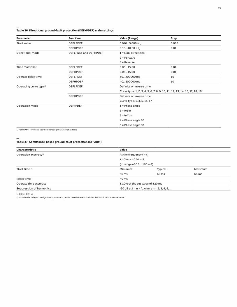
—Table 36. Directional ground-fault protection (DEFxPDEF) main settings
Parameter Function Value (Range) Step
Start value DEFLPDEF 0.010...5.000 × In 0.005
DEFHPDEF 0.10...40.00 × In 0.01
Directional mode DEFLPDEF and DEFHPDEF 1 = Non-directional -
2 = Forward
3 = Reverse
Time multiplier DEFLPDEF 0.05...15.00 0.01
DEFHPDEF 0.05...15.00 0.01
Operate delay time DEFLPDEF 50...200000 ms 10
DEFHPDEF 40...200000 ms 10
Operating curve type1) DEFLPDEF Definite or inverse time
Curve type: 1, 2, 3, 4, 5, 6, 7, 8, 9, 10, 11, 12, 13, 14, 15, 17, 18, 19
DEFHPDEF Definite or inverse time
Curve type: 1, 3, 5, 15, 17
Operation mode DEFxPDEF 1 = Phase angle
2 = IoSin
3 = IoCos
4 = Phase angle 80
5 = Phase angle 88
1) For further reference, see the Operating characteristics table
—Table 37. Admittance-based ground-fault protection (EFPADM)
Characteristic Value
Operation accuracy1) At the frequency f = fn
±1.0% or ±0.01 mS
(In range of 0.5... 100 mS)
Start time 2) Minimum Typical Maximum
56 ms 60 ms 64 ms
Reset time 40 ms
Operate time accuracy ±1.0% of the set value of ±20 ms
Suppression of harmonics -50 dB at f = n × fn, where n = 2, 3, 4, 5,…
1) 1) Uo = 1.0 × Un
2) Includes the delay of the signal output contact, results based on statistical distribution of 1000 measurements

36 R E D 61 5 L I N E D I FFER ENTI A L PR OTEC TI O N A N D CO NTR O L
—Table 38. Admittance-based ground-fault protection (EFPADM) main settings
Parameter Function Value (Range) Step
Voltage start value EFPADM 0.01...2.000 × Un 0.01
Directional mode EFPADM 1 = Non-directional -
2 = Forward
3 = Reverse
Operation mode EFPADM 1 = Yo -
2 = Go
3 = Bo
4 = Yo, Go
5 = Yo, Bo
6 = Go, Bo
7 = Yo, Go, Bo
Operate delay time EFPADM 60...200000 ms 10
Circle radius EFPADM 0.05...500.00 mS 0.01
Circle conductance EFPADM -500.00...500.00 mS 0.01
Circle susceptance EFPADM -500.00...500.00 mS 0.01
Conductance forward EFPADM -500.00...500.00 mS 0.01
Conductance reverse EFPADM -500.00...500.00 mS 0.01
Susceptance forward EFPADM -500.00...500.00 mS 0.01
Susceptance reverse EFPADM -500.00...500.00 mS 0.01
Conductance tilt Ang EFPADM -30...30° 1
Susceptance tilt Ang EFPADM -30...30° 1
—Table 39. Wattmetric-based ground-fault protection (WPWDE)
Characteristic Value
Operation accuracy1) Depending on the frequency of the measured current: fn ±2 Hz
Current and voltage:
±1.5% of the set value or ±0.002 × In
Power:
±3% of the set value or ±0.002 × Pn
Start time 1)2) Typically 63 ms
Reset time Typically 40 ms
Reset ratio Typically 0.96
Operate time accuracy in definite time mode ±1.0% of the set value or ±20 ms
Operate time accuracy in IDMT mode ±5.0% of the set value or ±20 ms
Suppression of harmonics -50 dB at f = n × fn, where n = 2,3,4,5,…
1) Io varied during the test, Uo = 1.0 × Un = phase to ground voltage during ground fault in compensated or un-grounded network, the residual power value before fault = 0.0 pu, fn = 50 Hz, results
based on statistical distribution of 1000 measurements
2) Includes the delay of the signal output contact

37
—Table 40. Wattmetric-based ground-fault protection (WPWDE) main settings
Parameter Function Value (Range) Step
Directional mode WPWDE 2 = Forward -
3 = Reverse
Current start value WPWDE 0.010...5.000 × In 0.001
Voltage start value WPWDE 0.010...1.000 × Un 0.001
Power start value WPWDE 0.003...1.000 × Pn 0.001
Reference power WPWDE 0.050...1.000 × Pn 0.001
Characteristic angle WPWDE -179...180° 1
Time multiplier WPWDE 0.05...2.00 0.01
Operating curve type1) WPWDE Definite or inverse time
Curve type: 5, 15, 20
Operate delay time WPWDE 60...200000 ms 10
Min operate current WPWDE 0.010...1.000 × In 0.001
Min operate voltage WPWDE 0.01...1.00 × Un 0.01
1) For further reference, see the Operating characteristics table
—Table 41. Transient/intermittent ground-fault protection (INTRPTEF)
Characteristic Value
Operation accuracy (Uo criteria with transient protection) Depending on the frequency of the measured current: fn ±2 Hz
±1.5% of the set value or ±0.002 × Uo
Operate time accuracy ±1.0% of the set value or ±20 ms
Suppression of harmonics DFT: -50 dB at f = n × fn, where n = 2, 3, 4, 5
—Table 42. Transient/intermittent ground-fault protection (INTRPTEF) main settings
Parameter Function Value (Range) Step
Directional mode INTRPTEF 1 = Non-directional -
2 = Forward
3 = Reverse
Operate delay time INTRPTEF 40...1200000 ms 10
Voltage start value INTRPTEF 0.05...0.50 × Un 0.01
Operation mode 1 = Intermittent EF -
2 = Transient EF
Peak counter limit INTRPTEF 2...20 1
Min operate current INTRPTEF 0.01...1.00 × In 0.01
38 R E D 61 5 L I N E D I FFER ENTI A L PR OTEC TI O N A N D CO NTR O L
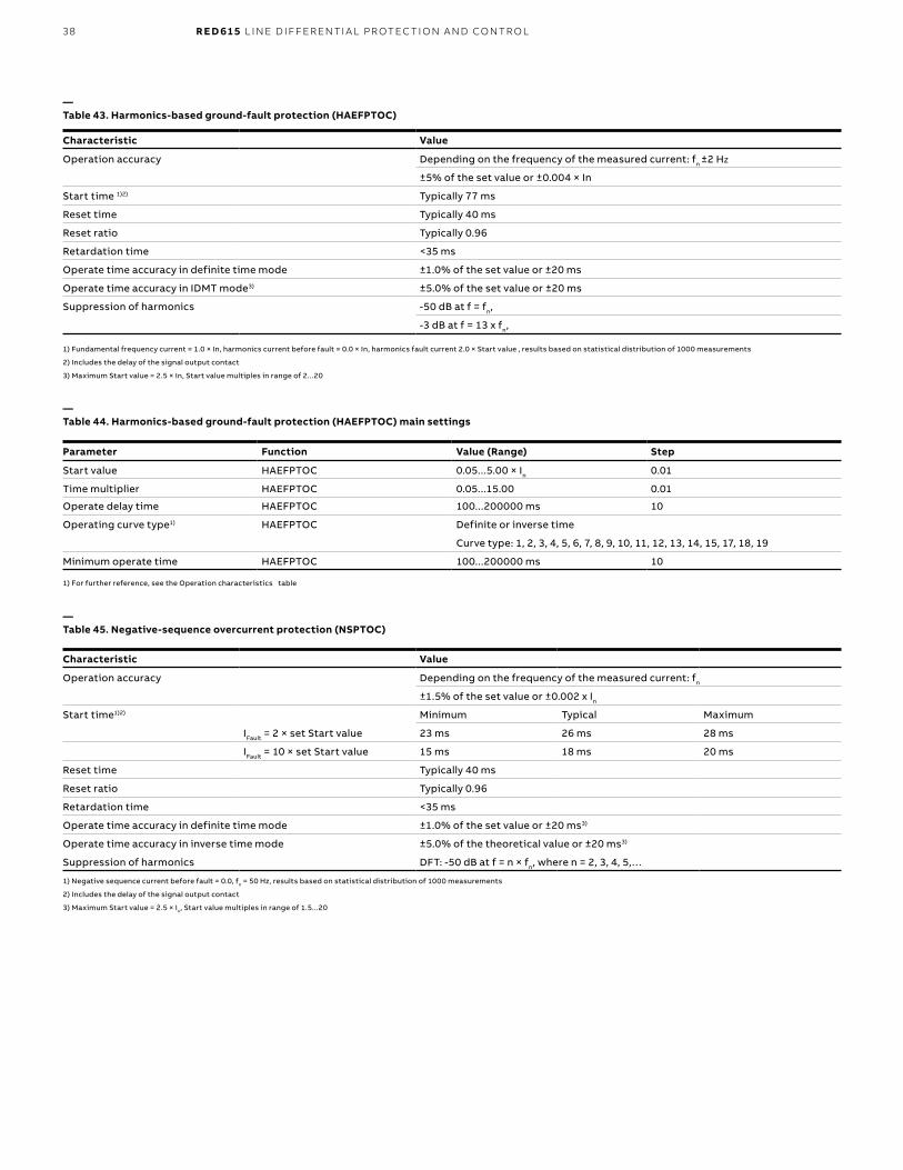
—Table 43. Harmonics-based ground-fault protection (HAEFPTOC)
Characteristic Value
Operation accuracy Depending on the frequency of the measured current: fn ±2 Hz
±5% of the set value or ±0.004 × In
Start time 1)2) Typically 77 ms
Reset time Typically 40 ms
Reset ratio Typically 0.96
Retardation time <35 ms
Operate time accuracy in definite time mode ±1.0% of the set value or ±20 ms
Operate time accuracy in IDMT mode3) ±5.0% of the set value or ±20 ms
Suppression of harmonics -50 dB at f = fn,
-3 dB at f = 13 x fn,
1) For further reference, see the Operation characteristics table
1) Fundamental frequency current = 1.0 × In, harmonics current before fault = 0.0 × In, harmonics fault current 2.0 × Start value , results based on statistical distribution of 1000 measurements
2) Includes the delay of the signal output contact
3) Maximum Start value = 2.5 × In, Start value multiples in range of 2...20
—Table 44. Harmonics-based ground-fault protection (HAEFPTOC) main settings
Parameter Function Value (Range) Step
Start value HAEFPTOC 0.05...5.00 × In 0.01
Time multiplier HAEFPTOC 0.05...15.00 0.01
Operate delay time HAEFPTOC 100...200000 ms 10
Operating curve type1) HAEFPTOC Definite or inverse time
Curve type: 1, 2, 3, 4, 5, 6, 7, 8, 9, 10, 11, 12, 13, 14, 15, 17, 18, 19
Minimum operate time HAEFPTOC 100...200000 ms 10
—Table 45. Negative-sequence overcurrent protection (NSPTOC)
Characteristic Value
Operation accuracy Depending on the frequency of the measured current: fn
±1.5% of the set value or ±0.002 x In
Start time1)2) Minimum Typical Maximum
IFault = 2 × set Start value 23 ms 26 ms 28 ms
IFault = 10 × set Start value 15 ms 18 ms 20 ms
Reset time Typically 40 ms
Reset ratio Typically 0.96
Retardation time <35 ms
Operate time accuracy in definite time mode ±1.0% of the set value or ±20 ms3)
Operate time accuracy in inverse time mode ±5.0% of the theoretical value or ±20 ms3)
Suppression of harmonics DFT: -50 dB at f = n × fn, where n = 2, 3, 4, 5,…
1) Negative sequence current before fault = 0.0, fn = 50 Hz, results based on statistical distribution of 1000 measurements
2) Includes the delay of the signal output contact
3) Maximum Start value = 2.5 × In, Start value multiples in range of 1.5...20
39
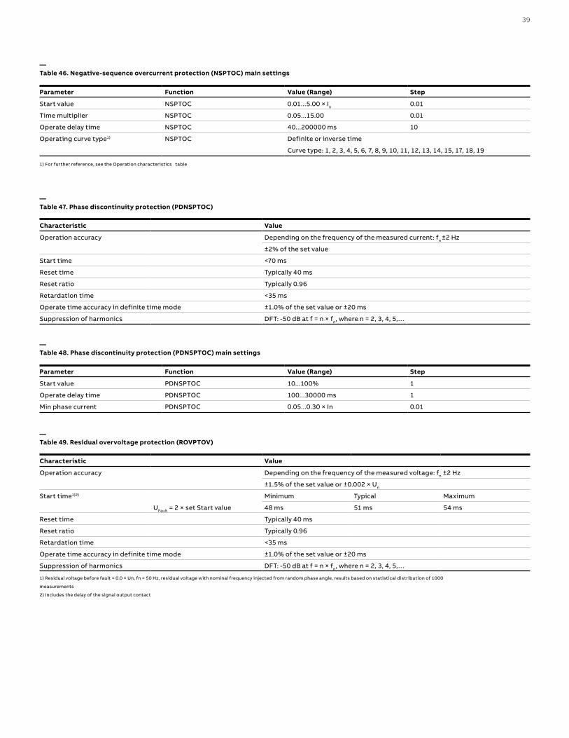
—Table 46. Negative-sequence overcurrent protection (NSPTOC) main settings
Parameter Function Value (Range) Step
Start value NSPTOC 0.01...5.00 × In 0.01
Time multiplier NSPTOC 0.05...15.00 0.01
Operate delay time NSPTOC 40...200000 ms 10
Operating curve type1) NSPTOC Definite or inverse time
Curve type: 1, 2, 3, 4, 5, 6, 7, 8, 9, 10, 11, 12, 13, 14, 15, 17, 18, 19
—Table 48. Phase discontinuity protection (PDNSPTOC) main settings
Parameter Function Value (Range) Step
Start value PDNSPTOC 10...100% 1
Operate delay time PDNSPTOC 100...30000 ms 1
Min phase current PDNSPTOC 0.05...0.30 × In 0.01
—Table 47. Phase discontinuity protection (PDNSPTOC)
Characteristic Value
Operation accuracy Depending on the frequency of the measured current: fn ±2 Hz
±2% of the set value
Start time <70 ms
Reset time Typically 40 ms
Reset ratio Typically 0.96
Retardation time <35 ms
Operate time accuracy in definite time mode ±1.0% of the set value or ±20 ms
Suppression of harmonics DFT: -50 dB at f = n × fn, where n = 2, 3, 4, 5,…
1) For further reference, see the Operation characteristics table
—Table 49. Residual overvoltage protection (ROVPTOV)
Characteristic Value
Operation accuracy Depending on the frequency of the measured voltage: fn ±2 Hz
±1.5% of the set value or ±0.002 × Un
Start time1)2) Minimum Typical Maximum
UFault = 2 × set Start value 48 ms 51 ms 54 ms
Reset time Typically 40 ms
Reset ratio Typically 0.96
Retardation time <35 ms
Operate time accuracy in definite time mode ±1.0% of the set value or ±20 ms
Suppression of harmonics DFT: -50 dB at f = n × fn, where n = 2, 3, 4, 5,…
1) Residual voltage before fault = 0.0 × Un, fn = 50 Hz, residual voltage with nominal frequency injected from random phase angle, results based on statistical distribution of 1000
measurements
2) Includes the delay of the signal output contact

40 R E D 61 5 L I N E D I FFER ENTI A L PR OTEC TI O N A N D CO NTR O L
—Table 51. Three-phase undervoltage protection (PHPTUV)
Characteristic Value
Operation accuracy Depending on the frequency of the voltage measured: fn ±2 Hz
±1.5% of the set value or ±0.002 × Un
Start time 1)2) Minimum Typical Maximum
UFault = 0.9 × set Start value 62 ms 66 ms 70 ms
Reset time Typically 40 ms
Reset ratio Depends on the set Relative hysteresis
Retardation time <35 ms
Operate time accuracy in definite time mode ±1.0% of the set value or ±20 ms
Operate time accuracy in inverse time mode ±5.0% of the theoretical value or ±20 ms3)
Suppression of harmonics DFT: -50 dB at f = n × fn, where n = 2, 3, 4, 5,…
1) For further reference, see the Operation characteristics table
1) Start value = 1.0 × Un, Voltage before fault = 1.1 × Un, fn = 50 Hz, undervoltage in one phase-to-phase with nominal frequency injected from random phase angle, results based on statistical
distribution of 1000 measurements
2) Includes the delay of the signal output contact
3) Minimum Start value = 0.50, Start value multiples in range of 0.90...0.20
—Table 50. Residual overvoltage protection (ROVPTOV) main settings
Parameter Function Value (Range) Step
Start value ROVPTOV 0.010...1.000 × Un 0.001
Operate delay time ROVPTOV 40...300000 ms 1
—Table 52. Three-phase undervoltage protection (PHPTUV) main settings
Characteristic Function Value Step
Start value PHPTUV 0.05...1.20 × Un 0.01
Time multiplier PHPTUV 0.05...15.00 0.01
Operate delay time PHPTUV 60...300000 ms 10
Operating curve type1) PHPTUV Definite or inverse time
Curve type: 5, 15, 21, 22, 23
1) For further reference, see the Operation characteristics table
—Table 53. Three-phase overvoltage protection (PHPTOV)
Characteristic Value
Operation accuracy Depending on the frequency of the measured voltage: fn ±2 Hz
±1.5% of the set value or ±0.002 × Un
Start time 1)2) Minimum Typical Maximum
UFault = 1.1 × set Start value 23 ms 27 ms 31 ms
Reset time Typically 40 ms
Reset ratio Depends on the set Relative hysteresis
Retardation time <35 ms
Operate time accuracy in definite time mode ±1.0% of the set value or ±20 ms
Operate time accuracy in inverse time mode ±5.0% of the theoretical value or ±20 ms3)
Suppression of harmonics DFT: -50 dB at f = n × fn, where n = 2, 3, 4, 5,…
1) Start value = 1.0 × Un, Voltage before fault = 0.9 × Un, fn = 50 Hz, overvoltage in one phase-to-phase with nominal frequency injected from random phase angle, results based on statistical
distribution of 1000 measurements
2) Includes the delay of the signal output contact
3) Maximum Start value = 1.20 × Un, Start value multiples in range of 1.10...2.00

41
—Table 55. Positive-sequence undervoltage protection (PSPTUV)
Characteristic Value
Operation accuracy Depending on the frequency of the measured voltage: fn ±2 Hz
±1.5% of the set value or ±0.002 × Un
Start time 1)2) Minimum Typical Maximum
UFault = 0.99 × set Start value 52 ms 55 ms 58 ms
UFault = 0.9 × set Start value 44 ms 47 ms 50 ms
Reset time Typically 40 ms
Reset ratio Depends on the set Relative hysteresis
Retardation time <35 ms
Operate time accuracy in definite time mode ±1.0% of the set value or ±20 ms
Suppression of harmonics DFT: -50 dB at f = n × fn, where n = 2, 3, 4, 5,…
1) Start value = 1.0 × Un, positive-sequence voltage before fault = 1.1 × Un, fn = 50 Hz, positive sequence undervoltage with nominal frequency injected from random phase angle, results based
on statistical distribution of 1000 measurements
2) Includes the delay of the signal output contact
1) For further reference, see the Operation characteristics table
—Table 54. Three-phase overvoltage protection (PHPTOV) main settings
Parameter Function Value (Range) Step
Start value PHPTOV 0.05...1.60 × Un 0.01
Time multiplier PHPTOV 0.05...15.00 0.01
Operate delay time PHPTOV 40...300000 ms 10
Operating curve type1) PHPTOV Definite or inverse time
Curve type: 5, 15, 17, 18, 19, 20
—Table 56. Positive-sequence undervoltage protection (PSPTUV) main settings
Parameter Function Value (Range) Step
Start value PSPTUV 0.010...1.200 × Un 0.001
Operate delay time PSPTUV 40...120000 ms 10
Voltage block value PSPTUV 0.01...1.00 × Un 0.01
1) Negative-sequence voltage before fault = 0.0 × Un, fn = 50 Hz, negative-sequence overvoltage with nominal frequency injected from random phase angle, results based on statistical
distribution of 1000 measurements
2) Includes the delay of the signal output contact
—Table 57. Negative-sequence overvoltage protection (NSPTOV)
Characteristic Value
Operation accuracy Depending on the frequency of the voltage measured: fn
±1.5% of the set value or ±0.002 × Un
Start time1)2) Minimum Typical Maximum
UFault = 1.1 × set Start value 33 ms 35 ms 37 ms
UFault = 2.0 × set Start value 24 ms 26 ms 28 ms
Reset time Typically 40 ms
Reset ratio Typically 0.96
Retardation time <35 ms
Operate time accuracy in definite time mode ±1.0% of the set value or ±20 ms
Suppression of harmonics DFT: -50 dB at f = n × fn, where n = 2, 3, 4, 5,…

42 R E D 61 5 L I N E D I FFER ENTI A L PR OTEC TI O N A N D CO NTR O L
—Table 59. Frequency protection (FRPFRQ)
Characteristic Value
Operation accuracy f>/f< ±5 mHz
df/dt ±50 mHz/s (in range |df/dt| <5 Hz/s)
±2.0% of the set value (in range 5 Hz/s < |df/dt| < 15 Hz/s)
Start time f>/f< <80 ms
df/dt <120 ms
Reset time <150 ms
Operate time accuracy ±1.0% of the set value or ±30 ms
1) Overload current > 1.2 × Operate level temperature
—Table 58. Negative-sequence overvoltage protection (NSPTOV) main settings
Parameter Function Value (Range) Step
Start value NSPTOV 0.010...1.000 × Un 0.001
Operate delay time NSPTOV 40...120000 ms 1
—Table 60. Frequency protection (FRPFRQ) main settings
Parameter Function Value (Range) Step
Operation mode FRPFRQ 1 = Freq< -
2 = Freq>
3 = df/dt
4 = Freq< + df/dt
5 = Freq> + df/dt
6 = Freq< OR df/dt
7 = Freq> OR df/dt
Start value Freq> FRPFRQ 0.9000...1.2000 × fn 0.0001
Start value Freq< FRPFRQ 0.8000...1.1000 × fn 0.0001
Start value df/dt FRPFRQ -0.2000...0.2000 × fn/s 0.005
Operate Tm Freq FRPFRQ 80...200000 ms 10
Operate Tm df/dt FRPFRQ 120...200000 ms 10
—Table 61. Three-phase thermal protection for feeders, cables and distribution transformers (T1PTTR)
Characteristic Value
Operation accuracy Depending on the frequency of the measured current: fn ±2 Hz
Current measurement: ±1.5% of the set value or ±0.002 × In (at currents
in the range of 0.01...4.00 × In)
Operate time accuracy1) ±2.0% of the theoretical value or ±0.50 s
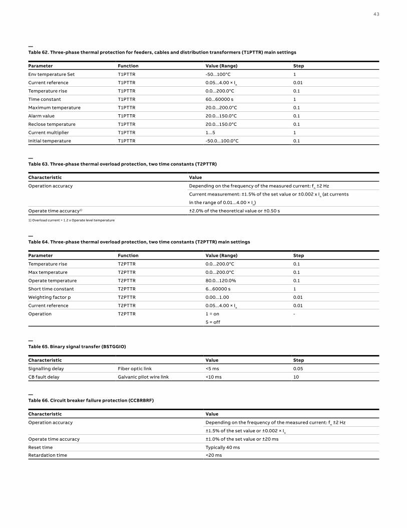
43
—Table 62. Three-phase thermal protection for feeders, cables and distribution transformers (T1PTTR) main settings
Parameter Function Value (Range) Step
Env temperature Set T1PTTR -50...100°C 1
Current reference T1PTTR 0.05...4.00 × In 0.01
Temperature rise T1PTTR 0.0...200.0°C 0.1
Time constant T1PTTR 60...60000 s 1
Maximum temperature T1PTTR 20.0...200.0°C 0.1
Alarm value T1PTTR 20.0...150.0°C 0.1
Reclose temperature T1PTTR 20.0...150.0°C 0.1
Current multiplier T1PTTR 1...5 1
Initial temperature T1PTTR -50.0...100.0°C 0.1
1) Overload current > 1.2 x Operate level temperature
—Table 63. Three-phase thermal overload protection, two time constants (T2PTTR)
Characteristic Value
Operation accuracy Depending on the frequency of the measured current: fn ±2 Hz
Current measurement: ±1.5% of the set value or ±0.002 x In (at currents
in the range of 0.01...4.00 × In)
Operate time accuracy1) ±2.0% of the theoretical value or ±0.50 s
—Table 64. Three-phase thermal overload protection, two time constants (T2PTTR) main settings
Parameter Function Value (Range) Step
Temperature rise T2PTTR 0.0...200.0°C 0.1
Max temperature T2PTTR 0.0...200.0°C 0.1
Operate temperature T2PTTR 80.0...120.0% 0.1
Short time constant T2PTTR 6...60000 s 1
Weighting factor p T2PTTR 0.00...1.00 0.01
Current reference T2PTTR 0.05...4.00 × In 0.01
Operation T2PTTR 1 = on -
5 = off
—Table 65. Binary signal transfer (BSTGGIO)
Characteristic Value Step
Signalling delay Fiber optic link <5 ms 0.05
CB fault delay Galvanic pilot wire link <10 ms 10
—Table 66. Circuit breaker failure protection (CCBRBRF)
Characteristic Value
Operation accuracy Depending on the frequency of the measured current: fn ±2 Hz
±1.5% of the set value or ±0.002 × In
Operate time accuracy ±1.0% of the set value or ±20 ms
Reset time Typically 40 ms
Retardation time <20 ms
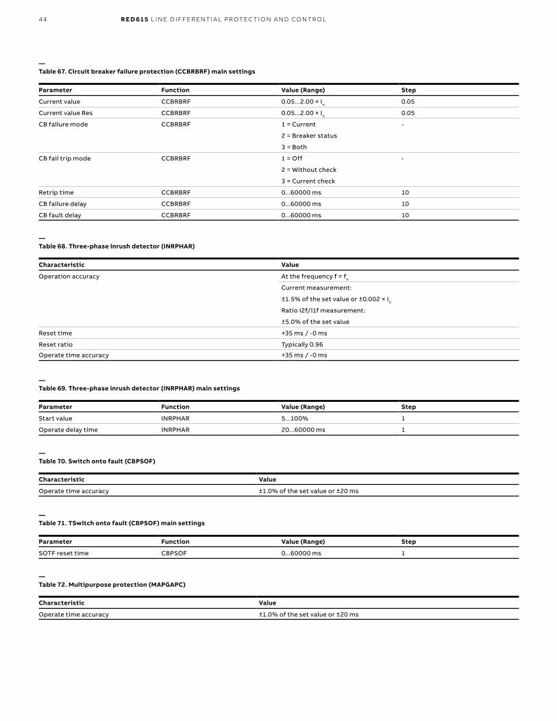
44 R E D 61 5 L I N E D I FFER ENTI A L PR OTEC TI O N A N D CO NTR O L
—Table 67. Circuit breaker failure protection (CCBRBRF) main settings
Parameter Function Value (Range) Step
Current value CCBRBRF 0.05...2.00 × In 0.05
Current value Res CCBRBRF 0.05...2.00 × In 0.05
CB failure mode CCBRBRF 1 = Current -
2 = Breaker status
3 = Both
CB fail trip mode CCBRBRF 1 = Off -
2 = Without check
3 = Current check
Retrip time CCBRBRF 0...60000 ms 10
CB failure delay CCBRBRF 0...60000 ms 10
CB fault delay CCBRBRF 0...60000 ms 10
—Table 69. Three-phase inrush detector (INRPHAR) main settings
Parameter Function Value (Range) Step
Start value INRPHAR 5...100% 1
Operate delay time INRPHAR 20...60000 ms 1
—Table 68. Three-phase inrush detector (INRPHAR)
Characteristic Value
Operation accuracy At the frequency f = fn
Current measurement:
±1.5% of the set value or ±0.002 × In
Ratio I2f/I1f measurement:
±5.0% of the set value
Reset time +35 ms / -0 ms
Reset ratio Typically 0.96
Operate time accuracy +35 ms / -0 ms
—Table 70. Switch onto fault (CBPSOF)
Characteristic Value
Operate time accuracy ±1.0% of the set value or ±20 ms
—Table 71. TSwitch onto fault (CBPSOF) main settings
Parameter Function Value (Range) Step
SOTF reset time CBPSOF 0...60000 ms 1
—Table 72. Multipurpose protection (MAPGAPC)
Characteristic Value
Operate time accuracy ±1.0% of the set value or ±20 ms
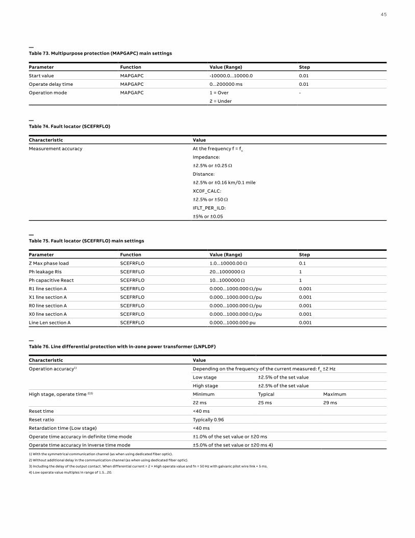
45
—Table 75. Fault locator (SCEFRFLO) main settings
Parameter Function Value (Range) Step
Z Max phase load SCEFRFLO 1.0...10000.00 Ω 0.1
Ph leakage Ris SCEFRFLO 20...1000000 Ω 1
Ph capacitive React SCEFRFLO 10...1000000 Ω 1
R1 line section A SCEFRFLO 0.000...1000.000 Ω/pu 0.001
X1 line section A SCEFRFLO 0.000...1000.000 Ω/pu 0.001
R0 line section A SCEFRFLO 0.000...1000.000 Ω/pu 0.001
X0 line section A SCEFRFLO 0.000...1000.000 Ω/pu 0.001
Line Len section A SCEFRFLO 0.000...1000.000 pu 0.001
—Table 76. Line differential protection with in-zone power transformer (LNPLDF)
Characteristic Value
Operation accuracy1) Depending on the frequency of the current measured: fn ±2 Hz
Low stage ±2.5% of the set value
High stage ±2.5% of the set value
High stage, operate time 2)3) Minimum Typical Maximum
22 ms 25 ms 29 ms
Reset time <40 ms
Reset ratio Typically 0.96
Retardation time (Low stage) <40 ms
Operate time accuracy in definite time mode ±1.0% of the set value or ±20 ms
Operate time accuracy in inverse time mode ±5.0% of the set value or ±20 ms 4)
1) With the symmetrical communication channel (as when using dedicated fiber optic).
2) Without additional delay in the communication channel (as when using dedicated fiber optic).
3) Including the delay of the output contact. When differential current = 2 × High operate value and fn = 50 Hz with galvanic pilot wire link + 5 ms.
4) Low operate value multiples in range of 1.5...20.
—Table 73. Multipurpose protection (MAPGAPC) main settings
Parameter Function Value (Range) Step
Start value MAPGAPC -10000.0...10000.0 0.01
Operate delay time MAPGAPC 0...200000 ms 0.01
Operation mode MAPGAPC 1 = Over -
2 = Under
—Table 74. Fault locator (SCEFRFLO)
Characteristic Value
Measurement accuracy At the frequency f = fn
Impedance:
±2.5% or ±0.25 Ω
Distance:
±2.5% or ±0.16 km/0.1 mile
XC0F_CALC:
±2.5% or ±50 Ω
IFLT_PER_ILD:
±5% or ±0.05

46 R E D 61 5 L I N E D I FFER ENTI A L PR OTEC TI O N A N D CO NTR O L
—Table 77. Line differential protection with in-zone power transformer (LNPLDF) main settings
Parameter Function Value (Range) Step
Low operate value LNPLDF 10...200 % In 1
High operate value LNPLDF 200...4000 % In 1
Start value 2.H LNPLDF 10...50 % 1
Time multiplier LNPLDF 0.05...15.00 0.01
Operate curve type LNPLDF 1=ANSI Ext. inv. -
3=ANSI Norm. inv.
5=ANSI Def. Time
9=IEC Norm. inv.
10=IEC Very inv.
12=IEC Ext. inv.
15=IEC Def. Time
Operate delay time LNPLDF 45...200000 ms 1
CT ratio correction LNPLDF 0.200...5.000 0.001
—Table 78. High-impedance fault detection (PHIZ) main settings
Parameter Function Value (Range) Step
Security Level PHIZ 1...10 1
System type PHIZ 1 = Grounded -
2 = Ungrounded

47
—Table 79. Operation characteristics
Characteristic Value
Operating curve type 1 = ANSI Ext. inv.
2 = ANSI Very. inv.
3 = ANSI Norm. inv.
4 = ANSI Mod inv.
5 = ANSI Def. Time
6 = L.T.E. inv.
7 = L.T.V. inv.
8 = L.T. inv.
9 = IEC Norm. inv.
10 = IEC Very inv.
11 = IEC inv.
12 = IEC Ext. inv.
13 = IEC S.T. inv.
14 = IEC L.T. inv
15 = IEC Def. Time
17 = Programmable
18 = RI type
19 = RD type
Operating curve type (voltage protection) 5 = ANSI Def. Time
15 = IEC Def. Time
17 = Inv. Curve A
18 = Inv. Curve B
19 = Inv. Curve C
20 = Programmable
21 = Inv. Curve A
22 = Inv. Curve B
23 = Programmable

48 R E D 61 5 L I N E D I FFER ENTI A L PR OTEC TI O N A N D CO NTR O L
—Table 81. Voltage variation (PHQVVR) main settings
Parameter Function Value (Range) Step
Voltage dip set 1 PHQVVR 10.0...100.0% 0.1
Voltage dip set 2 PHQVVR 10.0...100.0% 0.1
Voltage dip set 3 PHQVVR 10.0...100.0% 0.1
Voltage swell set 1 PHQVVR 100.0...140.0% 0.1
Voltage swell set 2 PHQVVR 100.0...140.0% 0.1
Voltage swell set 3 PHQVVR 100.0...140.0% 0.1
Voltage Int set PHQVVR 0.0...100.0% 0.1
VVa Dur Max PHQVVR 100...3600000 ms 100
Power quality functions
—Table 80. Three-phase underimpedance protection (UZPDIS) main settings
Characteristic Value
Operation accuracy ±1.5% of the set value or ±0.2% of reference voltage
Reset ratio Typically 0.96 (Swell), 1.04 (Dip, Interruption)
—Table 82. Voltage unbalance (VSQVUB)
Characteristic Value
Operation accuracy ±1.5% of the set value or ±0.002 × Un
Reset ratio Typically 0.96
—Table 83. Voltage unbalance (VSQVUB) main settings
Parameter Function Value (Range) Step
Operation VSQVUB 1 = on -
5 = off
Unb detection method VSQVUB 1 = Neg Seq
2 = Zero Seq
3 = Neg to Pos Seq
4 = Zero to Pos Seq
5 = Ph vectors Comp

49
—Table 84. Autoreclosing (DARREC)
Characteristic Value
Operate time accuracy ±1.0% of the set value or ±20 ms
—Table 86. Synchronism and energizing check (SECRSYN) main settings
Parameter Function Value (Range) Step
Live dead mode SECRSYN -1 = Off -
1 = Both Dead
2 = Live L, Dead B
3 = Dead L, Live B
4 = Dead Bus, L Any
5 = Dead L, Bus Any
6 = One Live, Dead
7 = Not Both Live
Difference voltage SECRSYN 0.01...0.50 × Un 0.01
Difference frequency SECRSYN 0.001...0.100 × fn 0.001
Difference angle SECRSYN 5...90° 1
Synchrocheck mode SECRSYN 1 = Off -
2 = Synchronous
3 = Asynchronous
Dead line value SECRSYN 0.1
Live line value SECRSYN 0.1
Max energizing V SECRSYN 0.01
Control mode SECRSYN 1 = Continuous -
2 = Command
Close pulse SECRSYN 200...60000 ms 10
Phase shift SECRSYN -180...180° 1
Minimum Syn time SECRSYN 0...60000 ms 10
Maximum Syn time SECRSYN 100...6000000 ms 10
Energizing time SECRSYN 100...60000 ms 10
Closing time of CB SECRSYN 40...250 ms 10
—Table 85. Synchronism and energizing check (SECRSYN)
Parameter Value (Range)
Operation accuracy Depending on the frequency of the voltage measured: fn ±1 Hz
Voltage:
±3.0% of the set value or ±0.01 × Un
Frequency:
±10 mHz
Phase angle:
±3°
Reset time <50 ms
Reset ratio Typically 0.96
Operate time accuracy in definite time mode ±1.0% of the set value or ±20 ms

50 R E D 61 5 L I N E D I FFER ENTI A L PR OTEC TI O N A N D CO NTR O L
1) Including the delay of the output contact
—Table 87. Circuit-breaker condition monitoring (SSCBR)
Characteristic Value
Current measuring accuracy ±1.5% or ±0.002 × In
(at currents in the range of 0.1…10 × In)
±5.0%
(at currents in the range of 10…40 × In)
Operate time accuracy ±1.0% of the set value or ±20 ms
Travelling time measurement +10 ms / -0 ms
Condition monitoring and supervision functions
—Table 88. Current circuit supervision (CCSPVC)
Characteristic Value
Operate time 1) <30 ms
—Table 89. Current circuit supervision (CCSPVC) main settings
Parameter Function Value (Range) Step
Start value CCSPVC 0.05...0.20 × In 0.01
Max operate current CCSPVC 1.00...5.00 × In 0.01
—Table 90. Fuse failure supervision (SEQSPVC
Parameter Function Value (Range) Step
Operate time1) NPS function UFault = 1.1 × set Neg Seq voltage <33 ms
Lev
UFault = 5.0 × set Neg Seq voltage <18 ms
Lev
Delta function ΔU = 1.1 × set Voltage change rate <30 ms
ΔU = 2.0 × set Voltage change rate <24 ms
1) Includes the delay of the signal output contact, fn = 50 Hz, fault voltage with nominal frequency injected from random phase angle, results based on statistical distribution of 1000 measurements
1) Of the reading, for a stand-alone relay, without time synchronization
—Table 91. Runtime counter for machines and devices (MDSOPT)
Characteristic Value
Motor runtime measurement accuracy1) ±0.5%
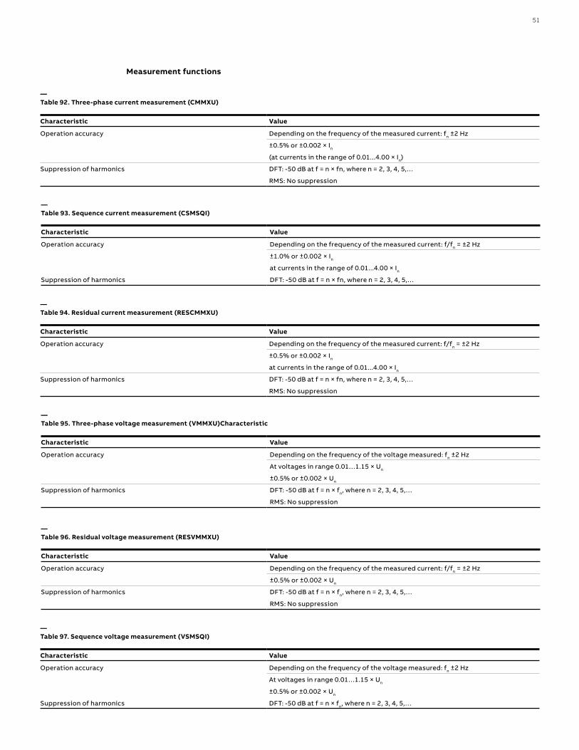
51
Measurement functions
—Table 92. Three-phase current measurement (CMMXU)
Characteristic Value
Operation accuracy Depending on the frequency of the measured current: fn ±2 Hz
±0.5% or ±0.002 × In
(at currents in the range of 0.01...4.00 × In)
Suppression of harmonics DFT: -50 dB at f = n × fn, where n = 2, 3, 4, 5,…
RMS: No suppression
—Table 93. Sequence current measurement (CSMSQI)
Characteristic Value
Operation accuracy Depending on the frequency of the measured current: f/fn = ±2 Hz
±1.0% or ±0.002 × In
at currents in the range of 0.01...4.00 × In
Suppression of harmonics DFT: -50 dB at f = n × fn, where n = 2, 3, 4, 5,…
—Table 94. Residual current measurement (RESCMMXU)
Characteristic Value
Operation accuracy Depending on the frequency of the measured current: f/fn = ±2 Hz
±0.5% or ±0.002 × In
at currents in the range of 0.01...4.00 × In
Suppression of harmonics DFT: -50 dB at f = n × fn, where n = 2, 3, 4, 5,…
RMS: No suppression
—Table 95. Three-phase voltage measurement (VMMXU)Characteristic
Characteristic Value
Operation accuracy Depending on the frequency of the voltage measured: fn ±2 Hz
At voltages in range 0.01…1.15 × Un
±0.5% or ±0.002 × Un
Suppression of harmonics DFT: -50 dB at f = n × fn, where n = 2, 3, 4, 5,…
RMS: No suppression
—Table 96. Residual voltage measurement (RESVMMXU)
Characteristic Value
Operation accuracy Depending on the frequency of the measured current: f/fn = ±2 Hz
±0.5% or ±0.002 × Un
Suppression of harmonics DFT: -50 dB at f = n × fn, where n = 2, 3, 4, 5,…
RMS: No suppression
—Table 97. Sequence voltage measurement (VSMSQI)
Characteristic Value
Operation accuracy Depending on the frequency of the voltage measured: fn ±2 Hz
At voltages in range 0.01…1.15 × Un
±0.5% or ±0.002 × Un
Suppression of harmonics DFT: -50 dB at f = n × fn, where n = 2, 3, 4, 5,…
52 R E D 61 5 L I N E D I FFER ENTI A L PR OTEC TI O N A N D CO NTR O L
—Table 98. Three-phase power and energy measurement (PEMMXU)
Characteristic Value
Operation accuracy At all three currents in range 0.10…1.20 × In
At all three voltages in range 0.50…1.15 × Un
At the frequency fn ±1 Hz
±1.5% for apparent power S
±1.5% for active power P and active energy1)
±1.5% for reactive power Q and reactive energy2)
±0.015 for power factor
Suppression of harmonics DFT: -50 dB at f = n × fn, where n = 2, 3, 4, 5,…
1) |PF| >0.5 which equals |cosφ| >0.5
2) |PF| <0.86 which equals |sinφ| >0.5
—Table 99. RTD/mA measurement (XRGGIO130)
Description Value
RTD inputs Supported RTD sensors 100 Ω platinum TCR 0.00385 (DIN 43760)
250 Ω platinum TCR 0.00385
100 Ω nickel TCR 0.00618 (DIN 43760)
120 Ω nickel TCR 0.00618
250 Ω nickel TCR 0.00618
10 Ω copper TCR 0.00427
Supported resistance range 0...2 kΩ
Maximum lead resistance (threewire
measurement) 25 Ω per lead
Isolation 2 kV (inputs to protective ground)
Response time <4 s
RTD/resistance sensing current Maximum 0.33 mA rms
Operation accuracy Resistance Temperature
± 2.0% or ±1 Ω ±1°C
10 Ω copper: ±2°C
mA inputs Supported current range 0…20 mA
Current input impedance 44 Ω ± 0.1%
Operation accuracy ±0.5% or ±0.01 mA
—Table 100. Frequency measurement (FMMXU)
Characteristic Value
Operation accuracy ±5 mHz
(in measurement range 35...75 Hz)
53
Other functions
—Table 101. Pulse timer (PTGAPC)
Characteristic Value
Operate time accuracy ±1.0% of the set value or ±20 ms
—Table 102. Time delay off (8 pcs) (TOFPAGC)
Characteristic Value
Operate time accuracy ±1.0% of the set value or ±20 ms
—Table 103. Time delay on (8 pcs) (TONGAPC)
Characteristic Value
Operate time accuracy ±1.0% of the set value or ±20 ms
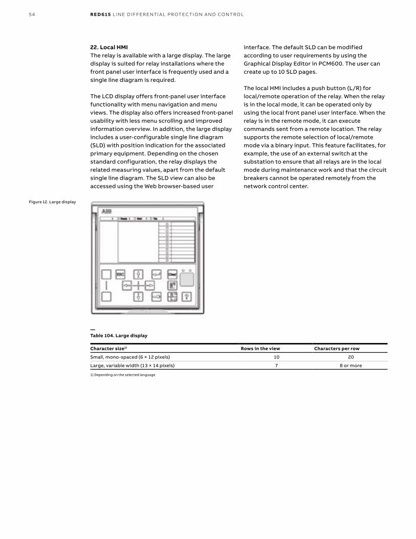
54 R E D 61 5 L I N E D I FFER ENTI A L PR OTEC TI O N A N D CO NTR O L
22. Local HMIThe relay is available with a large display. The large display is suited for relay installations where the front panel user interface is frequently used and a single line diagram is required.
The LCD display offers front-panel user interface functionality with menu navigation and menu views. The display also offers increased front-panel usability with less menu scrolling and improved information overview. In addition, the large display includes a user-configurable single line diagram (SLD) with position indication for the associated primary equipment. Depending on the chosen standard configuration, the relay displays the related measuring values, apart from the default single line diagram. The SLD view can also be accessed using the Web browser-based user
interface. The default SLD can be modified according to user requirements by using the Graphical Display Editor in PCM600. The user can create up to 10 SLD pages.
The local HMI includes a push button (L/R) for local/remote operation of the relay. When the relay is in the local mode, it can be operated only by using the local front panel user interface. When the relay is in the remote mode, it can execute commands sent from a remote location. The relay supports the remote selection of local/remote mode via a binary input. This feature facilitates, for example, the use of an external switch at the substation to ensure that all relays are in the local mode during maintenance work and that the circuit breakers cannot be operated remotely from the network control center.
Figure 12. Large display
—Table 104. Large display
Character size1) Rows in the view Characters per row
Small, mono-spaced (6 × 12 pixels) 10 20
Large, variable width (13 × 14 pixels) 7 8 or more
1) Depending on the selected language
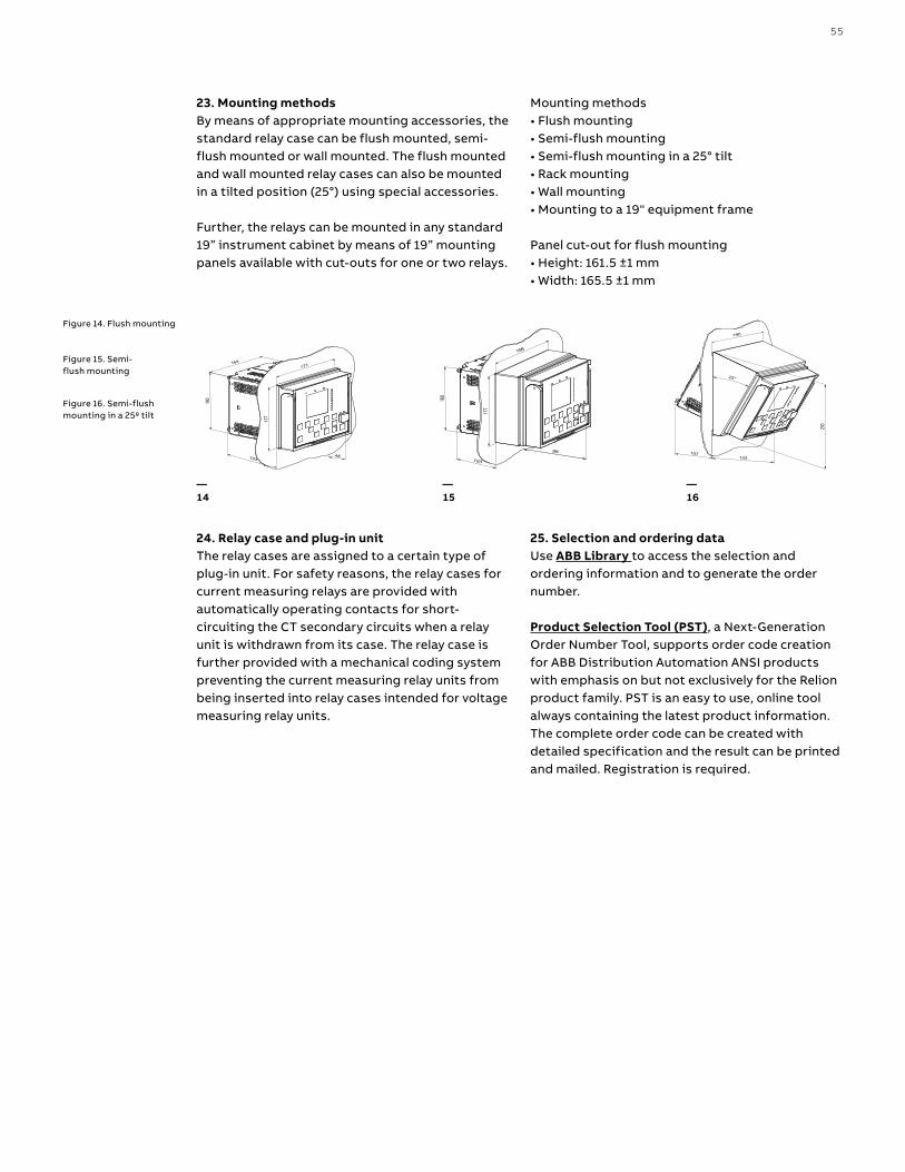
55
48
177
160
177
153
164
IECA070900 V4 EN
98
177
160
186
103
IECA070903 V4 EN
230
107
25°
133
190
IECA070902 V4 EN
23. Mounting methodsBy means of appropriate mounting accessories, the standard relay case can be flush mounted, semi-flush mounted or wall mounted. The flush mounted and wall mounted relay cases can also be mounted in a tilted position (25°) using special accessories.
Further, the relays can be mounted in any standard 19” instrument cabinet by means of 19” mounting panels available with cut-outs for one or two relays.
Mounting methods• Flush mounting• Semi-flush mounting• Semi-flush mounting in a 25° tilt• Rack mounting• Wall mounting• Mounting to a 19" equipment frame Panel cut-out for flush mounting• Height: 161.5 ±1 mm• Width: 165.5 ±1 mm
24. Relay case and plug-in unitThe relay cases are assigned to a certain type of plug-in unit. For safety reasons, the relay cases for current measuring relays are provided with automatically operating contacts for short-circuiting the CT secondary circuits when a relay unit is withdrawn from its case. The relay case is further provided with a mechanical coding system preventing the current measuring relay units from being inserted into relay cases intended for voltage measuring relay units.
25. Selection and ordering data Use ABB Library to access the selection and ordering information and to generate the order number.
Product Selection Tool (PST), a Next-Generation Order Number Tool, supports order code creation for ABB Distribution Automation ANSI products with emphasis on but not exclusively for the Relion product family. PST is an easy to use, online tool always containing the latest product information. The complete order code can be created with detailed specification and the result can be printed and mailed. Registration is required.
Figure 14. Flush mounting
Figure 15. Semi-flush mounting
Figure 16. Semi-flush mounting in a 25º tilt
—14
—15
—16
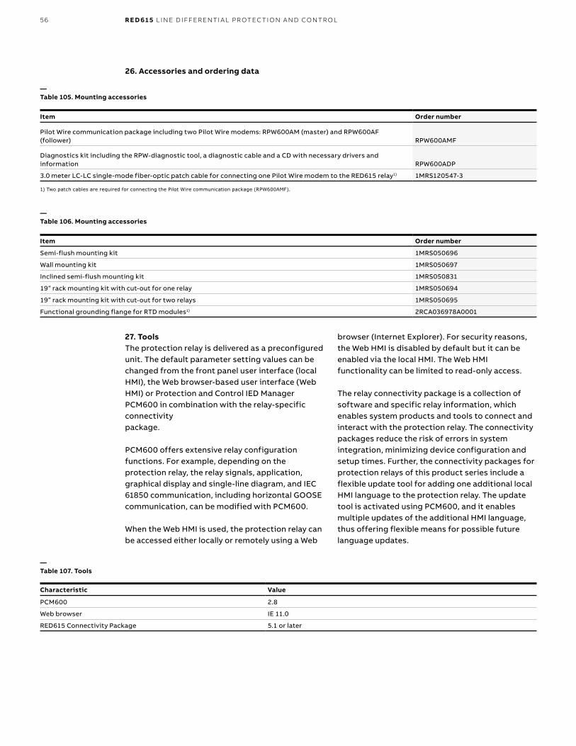
56 R E D 61 5 L I N E D I FFER ENTI A L PR OTEC TI O N A N D CO NTR O L
26. Accessories and ordering data
—Table 105. Mounting accessories
Item Order number
Pilot Wire communication package including two Pilot Wire modems: RPW600AM (master) and RPW600AF (follower) RPW600AMF
Diagnostics kit including the RPW-diagnostic tool, a diagnostic cable and a CD with necessary drivers and information RPW600ADP
3.0 meter LC-LC single-mode fiber-optic patch cable for connecting one Pilot Wire modem to the RED615 relay1) 1MRS120547-3
27. Tools The protection relay is delivered as a preconfigured unit. The default parameter setting values can be changed from the front panel user interface (local HMI), the Web browser-based user interface (Web HMI) or Protection and Control IED Manager PCM600 in combination with the relay-specific connectivitypackage.
PCM600 offers extensive relay configuration functions. For example, depending on the protection relay, the relay signals, application, graphical display and single-line diagram, and IEC 61850 communication, including horizontal GOOSE communication, can be modified with PCM600.
When the Web HMI is used, the protection relay can be accessed either locally or remotely using a Web
browser (Internet Explorer). For security reasons, the Web HMI is disabled by default but it can be enabled via the local HMI. The Web HMI functionality can be limited to read-only access. The relay connectivity package is a collection of software and specific relay information, which enables system products and tools to connect and interact with the protection relay. The connectivity packages reduce the risk of errors in system integration, minimizing device configuration and setup times. Further, the connectivity packages for protection relays of this product series include a flexible update tool for adding one additional local HMI language to the protection relay. The update tool is activated using PCM600, and it enables multiple updates of the additional HMI language, thus offering flexible means for possible future language updates.
—Table 107. Tools
Characteristic Value
PCM600 2.8
Web browser IE 11.0
RED615 Connectivity Package 5.1 or later
—Table 106. Mounting accessories
Item Order number
Semi-flush mounting kit 1MRS050696
Wall mounting kit 1MRS050697
Inclined semi-flush mounting kit 1MRS050831
19” rack mounting kit with cut-out for one relay 1MRS050694
19” rack mounting kit with cut-out for two relays 1MRS050695
Functional grounding flange for RTD modules1) 2RCA036978A0001
1) Two patch cables are required for connecting the Pilot Wire communication package (RPW600AMF).
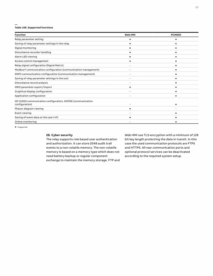
57
26. Accessories and ordering data—Table 108. Supported functions
Function Web HMI PCM600
Relay parameter setting ● ●
Saving of relay parameter settings in the relay ● ●
Signal monitoring ● ●
Disturbance recorder handling ● ●
Alarm LED viewing ● ●
Access control management ● ●
Relay signal configuration (Signal Matrix) - ●
Modbus® communication configuration (communication management) - ●
DNP3 communication configuration (communication management) - ●
Saving of relay parameter settings in the tool - ●
Disturbance record analysis - ●
XRIO parameter export/import ● ●
Graphical display configuration - ●
Application configuration - ●
IEC 61850 communication configuration, GOOSE (communication configuration) - ●
Phasor diagram viewing ● -
Event viewing - ●
Saving of event data on the user's PC ● ●
Online monitoring - ●
● = Supported
28. Cyber security The relay supports role based user authentication and authorization. It can store 2048 audit trail events to a non-volatile memory. The non-volatile memory is based on a memory type which does not need battery backup or regular component exchange to maintain the memory storage. FTP and
Web HMI use TLS encryption with a minimum of 128 bit key length protecting the data in transit. In this case the used communication protocols are FTPS and HTTPS. All rear communication ports and optional protocol services can be deactivated according to the required system setup.
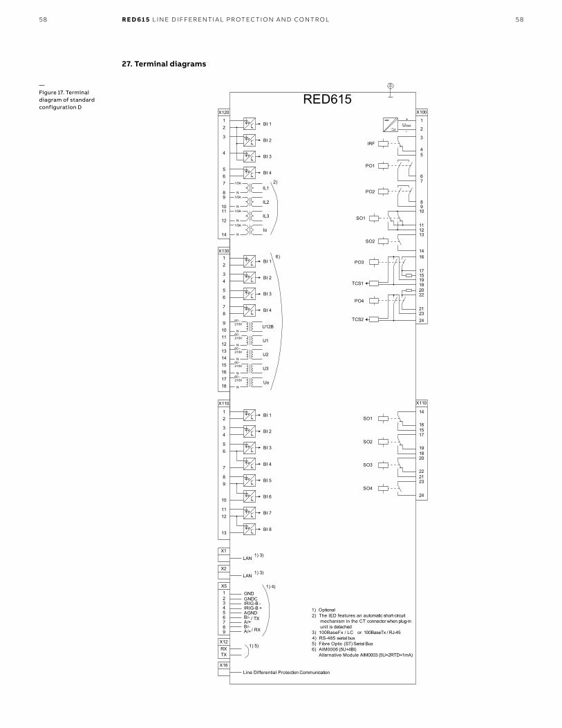
58
RED615
16
17
1918
X100
67
89
10
111213
15
14
2
1
3
45
22
212324
SO2
TCS2
PO4
SO1
TCS1
PO3
PO2
PO1
IRF
+
-Uaux
20
X110
34
56
7
89
10BI 6
BI 5
BI 4
BI 3
BI 2
BI 8
BI 712
13
11
BI 112
X110
16
14
15
19
17
18
22
20
21
SO3
SO2
SO1
23SO4
24
2)
X120
12
3
4
567
89
1011
12
14Io
IL1
IL2
BI 4
BI 3
BI 2
BI 1
IL3
1/5A
N1/5A
N1/5A
N1/5A
N
X13012
34
56
BI 4
BI 3
BI 2
BI 1
87
9101112
U12B
1314
U1
1516
U2
1718
U3
UoN
N
N
N
60 -
N
210V
60 -210V
60 -210V
60 -210V
60 -210V
6)
X1LAN
X5123456789
B/-A/+
/ TX
/ RX
GNDGNDC
X16Line Differential Protection Communication
X2LAN
IRIG-B -IRIG-B +AGND
1) 3)
X12RXTX
1) 3)
1) 4)
1) 5)
B/-A/+
1) Optional2) The IED features an automatic short-circuit mechanism in the CT connector when plug-in unit is detached3) 100BaseFx / LC or 100BaseTx / RJ-454) RS-485 serial bus5) Fibre Optic (ST) Serial Bus6) AIM0006 (5U+4BI) Alternative Module AIM0003 (5U+2RTD+1mA)
58 R E D 61 5 L I N E D I FFER ENTI A L PR OTEC TI O N A N D CO NTR O L
—Figure 17. Terminal diagram of standard configuration D
27. Terminal diagrams
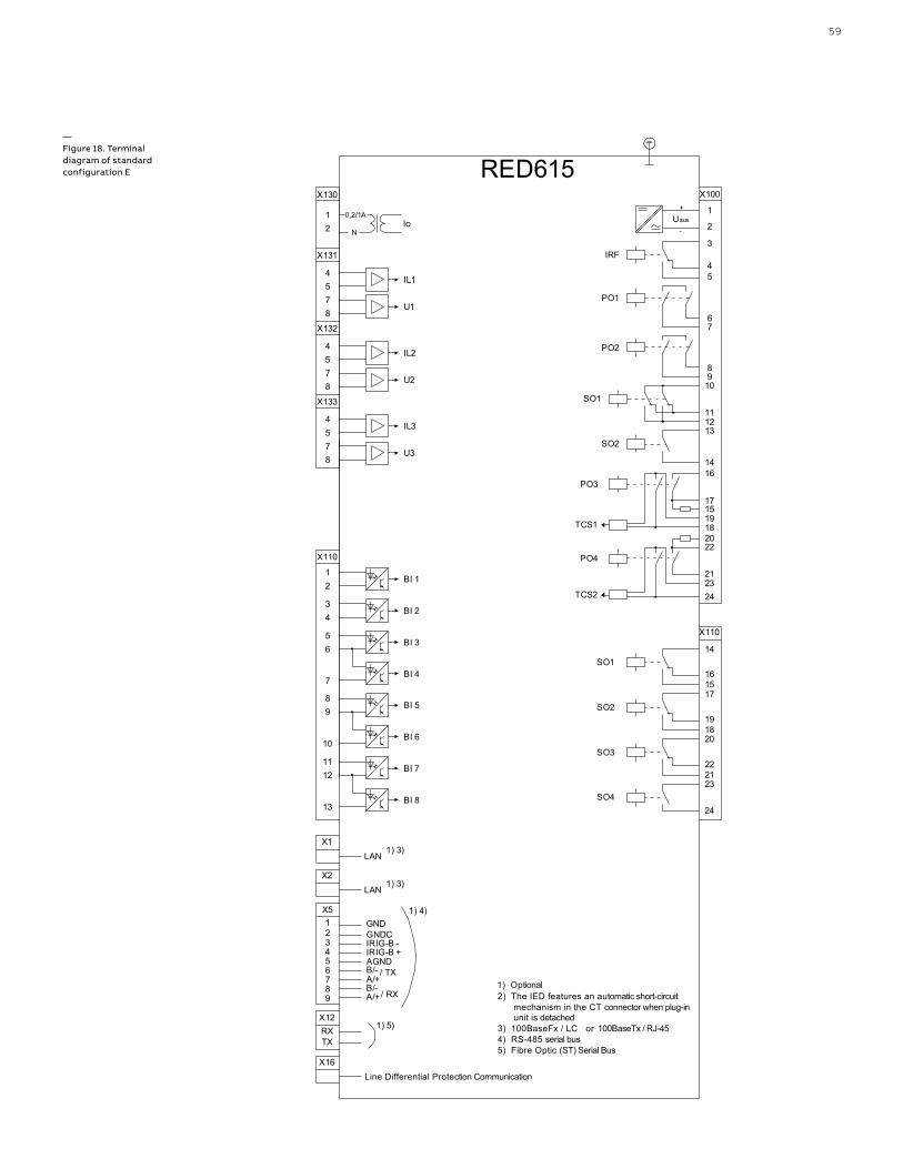
59
RED615
16
17
1918
X100
67
89
10
111213
15
14
2
1
3
45
22
212324
SO2
TCS2
PO4
SO1
TCS1
PO3
PO2
PO1
IRF
+
-Uaux
20
X110
34
56
7
89
10BI 6
BI 5
BI 4
BI 3
BI 2
BI 8
BI 712
13
11
BI 112
X110
16
14
15
19
17
18
22
20
21
SO3
SO2
SO1
23SO4
24
X1LAN
X5123456789
B/-A/+
/ TX
/ RX
GNDGNDC
X16Line Differential Protection Communication
X2LAN
IRIG-B -IRIG-B +AGND
1) 3)
X12RXTX
1) 3)
1) 4)
1) 5)
B/-A/+
1) Optional2) The IED features an automatic short-circuit mechanism in the CT connector when plug-in unit is detached3) 100BaseFx / LC or 100BaseTx / RJ-454) RS-485 serial bus5) Fibre Optic (ST) Serial Bus
X130
12
X131
45
IL1
78
U1
X132
45
IL2
78
U2
X133
45
IL3
78
U3
Io0,2/1A
N
—Figure 18. Terminal diagram of standard configuration E
60 R E D 61 5 L I N E D I FFER ENTI A L PR OTEC TI O N A N D CO NTR O L
28. CertificatesDNV GL has issued an IEC 61850 Edition 2 Certificate Level A1 for Relion® 615 series. Certificate number: 7410570I-OPE/INC 15-1136.
DNV GL has issued an IEC 61850 Edition 1 Certificate Level A1 for Relion® 615 series. Certificate number: 74105701-OPE/INC 15-1145.
Additional certificates can be found on the product page.
29. ReferencesThe www.abb.com/substationautomation portal provides information on the entire range of distribution automation products and services. The latest relevant information on the RED615 protection and control relay is found on the product page. Scroll down the page to find and download the related documentation.
For information regarding the RPW600 modems please refer to the RPW600 User’s Guide, document id 6621-2260. The document is available for download on the RED615 product page. Scroll down the page to find and download the related documentation.
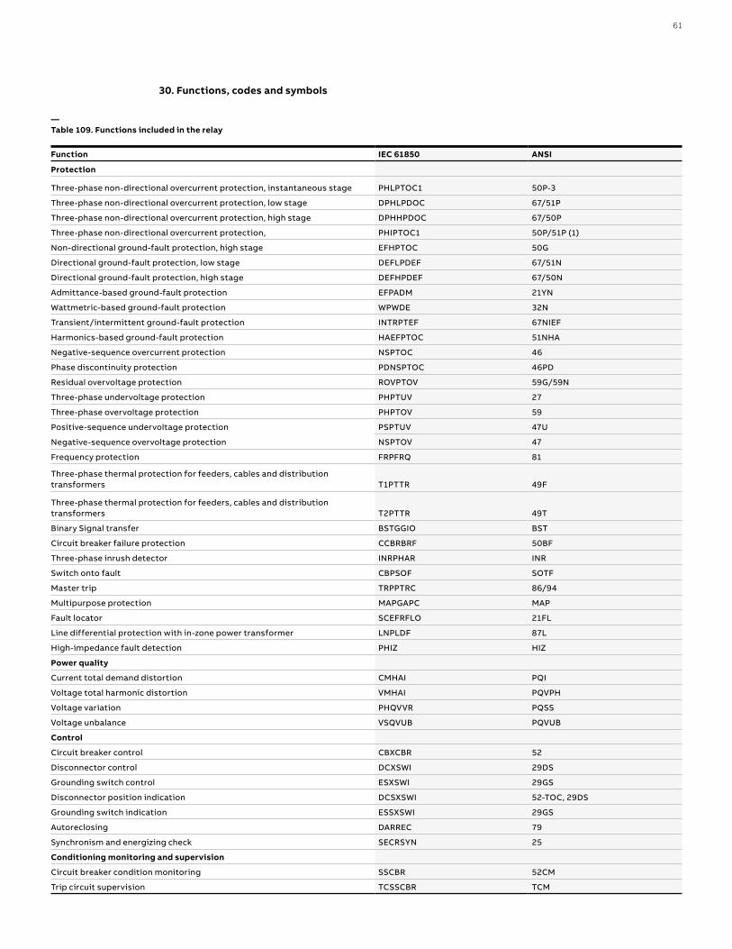
61
—Table 109. Functions included in the relay
Function IEC 61850 ANSI
Protection
Three-phase non-directional overcurrent protection, instantaneous stage PHLPTOC1 50P-3
Three-phase non-directional overcurrent protection, low stage DPHLPDOC 67/51P
Three-phase non-directional overcurrent protection, high stage DPHHPDOC 67/50P
Three-phase non-directional overcurrent protection, PHIPTOC1 50P/51P (1)
Non-directional ground-fault protection, high stage EFHPTOC 50G
Directional ground-fault protection, low stage DEFLPDEF 67/51N
Directional ground-fault protection, high stage DEFHPDEF 67/50N
Admittance-based ground-fault protection EFPADM 21YN
Wattmetric-based ground-fault protection WPWDE 32N
Transient/intermittent ground-fault protection INTRPTEF 67NIEF
Harmonics-based ground-fault protection HAEFPTOC 51NHA
Negative-sequence overcurrent protection NSPTOC 46
Phase discontinuity protection PDNSPTOC 46PD
Residual overvoltage protection ROVPTOV 59G/59N
Three-phase undervoltage protection PHPTUV 27
Three-phase overvoltage protection PHPTOV 59
Positive-sequence undervoltage protection PSPTUV 47U
Negative-sequence overvoltage protection NSPTOV 47
Frequency protection FRPFRQ 81
Three-phase thermal protection for feeders, cables and distribution transformers T1PTTR 49F
Three-phase thermal protection for feeders, cables and distribution transformers T2PTTR 49T
Binary Signal transfer BSTGGIO BST
Circuit breaker failure protection CCBRBRF 50BF
Three-phase inrush detector INRPHAR INR
Switch onto fault CBPSOF SOTF
Master trip TRPPTRC 86/94
Multipurpose protection MAPGAPC MAP
Fault locator SCEFRFLO 21FL
Line differential protection with in-zone power transformer LNPLDF 87L
High-impedance fault detection PHIZ HIZ
Power quality
Current total demand distortion CMHAI PQI
Voltage total harmonic distortion VMHAI PQVPH
Voltage variation PHQVVR PQSS
Voltage unbalance VSQVUB PQVUB
Control
Circuit breaker control CBXCBR 52
Disconnector control DCXSWI 29DS
Grounding switch control ESXSWI 29GS
Disconnector position indication DCSXSWI 52-TOC, 29DS
Grounding switch indication ESSXSWI 29GS
Autoreclosing DARREC 79
Synchronism and energizing check SECRSYN 25
Conditioning monitoring and supervision
Circuit breaker condition monitoring SSCBR 52CM
Trip circuit supervision TCSSCBR TCM
30. Functions, codes and symbols
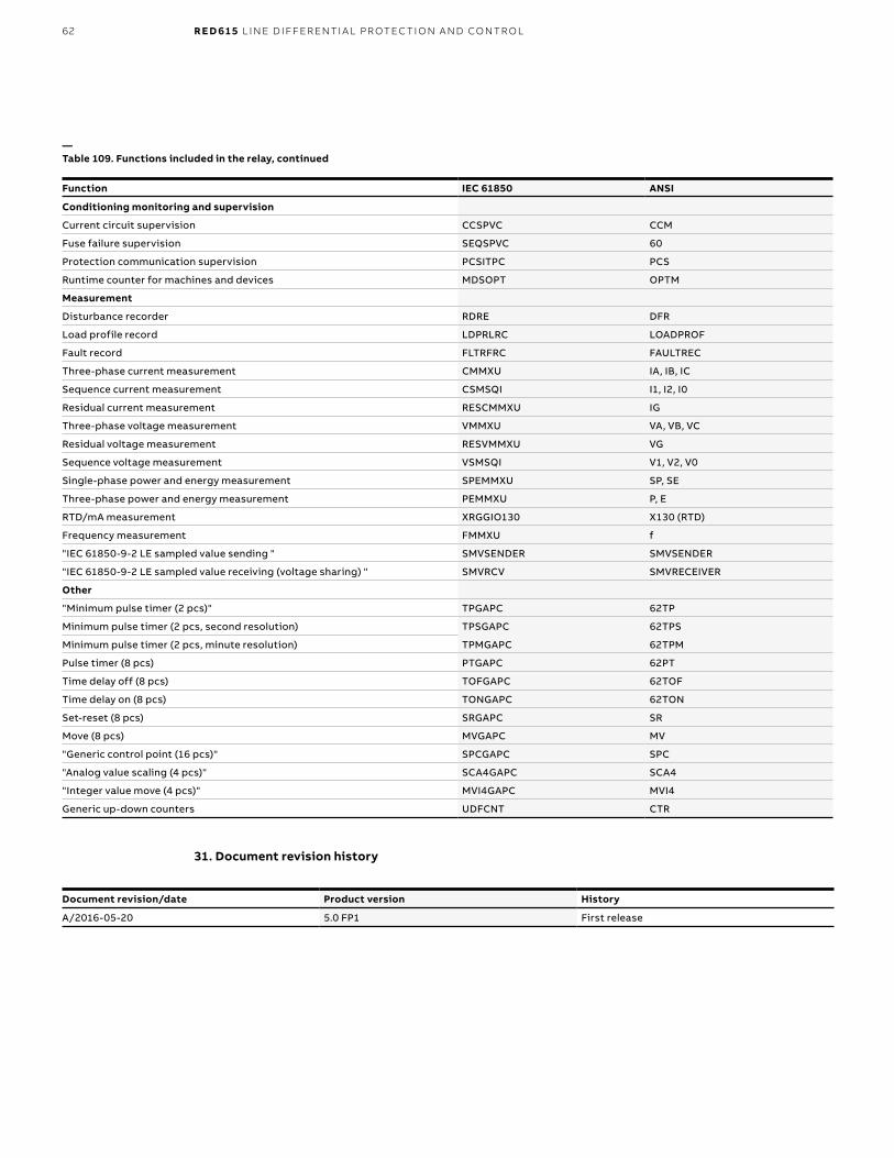
62 R E D 61 5 L I N E D I FFER ENTI A L PR OTEC TI O N A N D CO NTR O L
—Table 109. Functions included in the relay, continued
Function IEC 61850 ANSI
Conditioning monitoring and supervision
Current circuit supervision CCSPVC CCM
Fuse failure supervision SEQSPVC 60
Protection communication supervision PCSITPC PCS
Runtime counter for machines and devices MDSOPT OPTM
Measurement
Disturbance recorder RDRE DFR
Load profile record LDPRLRC LOADPROF
Fault record FLTRFRC FAULTREC
Three-phase current measurement CMMXU IA, IB, IC
Sequence current measurement CSMSQI I1, I2, I0
Residual current measurement RESCMMXU IG
Three-phase voltage measurement VMMXU VA, VB, VC
Residual voltage measurement RESVMMXU VG
Sequence voltage measurement VSMSQI V1, V2, V0
Single-phase power and energy measurement SPEMMXU SP, SE
Three-phase power and energy measurement PEMMXU P, E
RTD/mA measurement XRGGIO130 X130 (RTD)
Frequency measurement FMMXU f
"IEC 61850-9-2 LE sampled value sending " SMVSENDER SMVSENDER
"IEC 61850-9-2 LE sampled value receiving (voltage sharing) " SMVRCV SMVRECEIVER
Other
"Minimum pulse timer (2 pcs)" TPGAPC 62TP
Minimum pulse timer (2 pcs, second resolution) TPSGAPC 62TPS
Minimum pulse timer (2 pcs, minute resolution) TPMGAPC 62TPM
Pulse timer (8 pcs) PTGAPC 62PT
Time delay off (8 pcs) TOFGAPC 62TOF
Time delay on (8 pcs) TONGAPC 62TON
Set-reset (8 pcs) SRGAPC SR
Move (8 pcs) MVGAPC MV
"Generic control point (16 pcs)" SPCGAPC SPC
"Analog value scaling (4 pcs)" SCA4GAPC SCA4
"Integer value move (4 pcs)" MVI4GAPC MVI4
Generic up-down counters UDFCNT CTR
31. Document revision history
Document revision/date Product version History
A/2016-05-20 5.0 FP1 First release

63
Notes

—ABB Inc.4300 Coral Ridge Drive Coral Springs, FL 33065Phone: +1 954 752 6700 abb.com/mediumvoltageabb.com/substationautomation
1MA
C8
010
50
-PG
RE
V A
JA
N.2
018
© Copyright 2017 ABB. All rights reserved. Specifications subject to change without notice.